EP3851800B1 - Travel route creation system - Google Patents
Travel route creation system Download PDFInfo
- Publication number
- EP3851800B1 EP3851800B1 EP19860371.4A EP19860371A EP3851800B1 EP 3851800 B1 EP3851800 B1 EP 3851800B1 EP 19860371 A EP19860371 A EP 19860371A EP 3851800 B1 EP3851800 B1 EP 3851800B1
- Authority
- EP
- European Patent Office
- Prior art keywords
- personal mobility
- mobility vehicle
- travel route
- travel
- controller
- Prior art date
- Legal status (The legal status is an assumption and is not a legal conclusion. Google has not performed a legal analysis and makes no representation as to the accuracy of the status listed.)
- Active
Links
Images


Classifications
-
- G—PHYSICS
- G05—CONTROLLING; REGULATING
- G05D—SYSTEMS FOR CONTROLLING OR REGULATING NON-ELECTRIC VARIABLES
- G05D1/00—Control of position, course, altitude or attitude of land, water, air or space vehicles, e.g. using automatic pilots
- G05D1/40—Control within particular dimensions
- G05D1/43—Control of position or course in two dimensions [2D]
- G05D1/435—Control of position or course in two dimensions [2D] resulting in a change of level, e.g. negotiating lifts or stairs
-
- A—HUMAN NECESSITIES
- A61—MEDICAL OR VETERINARY SCIENCE; HYGIENE
- A61G—TRANSPORT, PERSONAL CONVEYANCES, OR ACCOMMODATION SPECIALLY ADAPTED FOR PATIENTS OR DISABLED PERSONS; OPERATING TABLES OR CHAIRS; CHAIRS FOR DENTISTRY; FUNERAL DEVICES
- A61G5/00—Chairs or personal conveyances specially adapted for patients or disabled persons, e.g. wheelchairs
- A61G5/04—Chairs or personal conveyances specially adapted for patients or disabled persons, e.g. wheelchairs motor-driven
- A61G5/041—Chairs or personal conveyances specially adapted for patients or disabled persons, e.g. wheelchairs motor-driven having a specific drive-type
- A61G5/045—Rear wheel drive
-
- A—HUMAN NECESSITIES
- A61—MEDICAL OR VETERINARY SCIENCE; HYGIENE
- A61G—TRANSPORT, PERSONAL CONVEYANCES, OR ACCOMMODATION SPECIALLY ADAPTED FOR PATIENTS OR DISABLED PERSONS; OPERATING TABLES OR CHAIRS; CHAIRS FOR DENTISTRY; FUNERAL DEVICES
- A61G5/00—Chairs or personal conveyances specially adapted for patients or disabled persons, e.g. wheelchairs
- A61G5/04—Chairs or personal conveyances specially adapted for patients or disabled persons, e.g. wheelchairs motor-driven
-
- A—HUMAN NECESSITIES
- A61—MEDICAL OR VETERINARY SCIENCE; HYGIENE
- A61G—TRANSPORT, PERSONAL CONVEYANCES, OR ACCOMMODATION SPECIALLY ADAPTED FOR PATIENTS OR DISABLED PERSONS; OPERATING TABLES OR CHAIRS; CHAIRS FOR DENTISTRY; FUNERAL DEVICES
- A61G5/00—Chairs or personal conveyances specially adapted for patients or disabled persons, e.g. wheelchairs
- A61G5/10—Parts, details or accessories
- A61G5/1051—Arrangements for steering
-
- B—PERFORMING OPERATIONS; TRANSPORTING
- B60—VEHICLES IN GENERAL
- B60W—CONJOINT CONTROL OF VEHICLE SUB-UNITS OF DIFFERENT TYPE OR DIFFERENT FUNCTION; CONTROL SYSTEMS SPECIALLY ADAPTED FOR HYBRID VEHICLES; ROAD VEHICLE DRIVE CONTROL SYSTEMS FOR PURPOSES NOT RELATED TO THE CONTROL OF A PARTICULAR SUB-UNIT
- B60W40/00—Estimation or calculation of non-directly measurable driving parameters for road vehicle drive control systems not related to the control of a particular sub unit, e.g. by using mathematical models
- B60W40/02—Estimation or calculation of non-directly measurable driving parameters for road vehicle drive control systems not related to the control of a particular sub unit, e.g. by using mathematical models related to ambient conditions
- B60W40/06—Road conditions
- B60W40/076—Slope angle of the road
-
- G—PHYSICS
- G01—MEASURING; TESTING
- G01C—MEASURING DISTANCES, LEVELS OR BEARINGS; SURVEYING; NAVIGATION; GYROSCOPIC INSTRUMENTS; PHOTOGRAMMETRY OR VIDEOGRAMMETRY
- G01C21/00—Navigation; Navigational instruments not provided for in groups G01C1/00 - G01C19/00
- G01C21/20—Instruments for performing navigational calculations
-
- G—PHYSICS
- G01—MEASURING; TESTING
- G01C—MEASURING DISTANCES, LEVELS OR BEARINGS; SURVEYING; NAVIGATION; GYROSCOPIC INSTRUMENTS; PHOTOGRAMMETRY OR VIDEOGRAMMETRY
- G01C21/00—Navigation; Navigational instruments not provided for in groups G01C1/00 - G01C19/00
- G01C21/26—Navigation; Navigational instruments not provided for in groups G01C1/00 - G01C19/00 specially adapted for navigation in a road network
- G01C21/34—Route searching; Route guidance
-
- G—PHYSICS
- G05—CONTROLLING; REGULATING
- G05D—SYSTEMS FOR CONTROLLING OR REGULATING NON-ELECTRIC VARIABLES
- G05D1/00—Control of position, course, altitude or attitude of land, water, air or space vehicles, e.g. using automatic pilots
- G05D1/02—Control of position or course in two dimensions
- G05D1/021—Control of position or course in two dimensions specially adapted to land vehicles
- G05D1/0212—Control of position or course in two dimensions specially adapted to land vehicles with means for defining a desired trajectory
- G05D1/0214—Control of position or course in two dimensions specially adapted to land vehicles with means for defining a desired trajectory in accordance with safety or protection criteria, e.g. avoiding hazardous areas
-
- G—PHYSICS
- G05—CONTROLLING; REGULATING
- G05D—SYSTEMS FOR CONTROLLING OR REGULATING NON-ELECTRIC VARIABLES
- G05D1/00—Control of position, course, altitude or attitude of land, water, air or space vehicles, e.g. using automatic pilots
- G05D1/02—Control of position or course in two dimensions
- G05D1/021—Control of position or course in two dimensions specially adapted to land vehicles
- G05D1/0268—Control of position or course in two dimensions specially adapted to land vehicles using internal positioning means
- G05D1/0274—Control of position or course in two dimensions specially adapted to land vehicles using internal positioning means using mapping information stored in a memory device
-
- G—PHYSICS
- G05—CONTROLLING; REGULATING
- G05D—SYSTEMS FOR CONTROLLING OR REGULATING NON-ELECTRIC VARIABLES
- G05D1/00—Control of position, course, altitude or attitude of land, water, air or space vehicles, e.g. using automatic pilots
- G05D1/20—Control system inputs
- G05D1/24—Arrangements for determining position or orientation
- G05D1/246—Arrangements for determining position or orientation using environment maps, e.g. simultaneous localisation and mapping [SLAM]
-
- G—PHYSICS
- G05—CONTROLLING; REGULATING
- G05D—SYSTEMS FOR CONTROLLING OR REGULATING NON-ELECTRIC VARIABLES
- G05D1/00—Control of position, course, altitude or attitude of land, water, air or space vehicles, e.g. using automatic pilots
- G05D1/60—Intended control result
- G05D1/617—Safety or protection, e.g. defining protection zones around obstacles or avoiding hazards
- G05D1/639—Resolving or avoiding being stuck or obstructed
-
- G—PHYSICS
- G05—CONTROLLING; REGULATING
- G05D—SYSTEMS FOR CONTROLLING OR REGULATING NON-ELECTRIC VARIABLES
- G05D1/00—Control of position, course, altitude or attitude of land, water, air or space vehicles, e.g. using automatic pilots
- G05D1/60—Intended control result
- G05D1/646—Following a predefined trajectory, e.g. a line marked on the floor or a flight path
-
- A—HUMAN NECESSITIES
- A61—MEDICAL OR VETERINARY SCIENCE; HYGIENE
- A61G—TRANSPORT, PERSONAL CONVEYANCES, OR ACCOMMODATION SPECIALLY ADAPTED FOR PATIENTS OR DISABLED PERSONS; OPERATING TABLES OR CHAIRS; CHAIRS FOR DENTISTRY; FUNERAL DEVICES
- A61G2203/00—General characteristics of devices
- A61G2203/10—General characteristics of devices characterised by specific control means, e.g. for adjustment or steering
- A61G2203/14—Joysticks
-
- A—HUMAN NECESSITIES
- A61—MEDICAL OR VETERINARY SCIENCE; HYGIENE
- A61G—TRANSPORT, PERSONAL CONVEYANCES, OR ACCOMMODATION SPECIALLY ADAPTED FOR PATIENTS OR DISABLED PERSONS; OPERATING TABLES OR CHAIRS; CHAIRS FOR DENTISTRY; FUNERAL DEVICES
- A61G2203/00—General characteristics of devices
- A61G2203/10—General characteristics of devices characterised by specific control means, e.g. for adjustment or steering
- A61G2203/22—General characteristics of devices characterised by specific control means, e.g. for adjustment or steering for automatically guiding movable devices, e.g. stretchers or wheelchairs in a hospital
-
- A—HUMAN NECESSITIES
- A61—MEDICAL OR VETERINARY SCIENCE; HYGIENE
- A61G—TRANSPORT, PERSONAL CONVEYANCES, OR ACCOMMODATION SPECIALLY ADAPTED FOR PATIENTS OR DISABLED PERSONS; OPERATING TABLES OR CHAIRS; CHAIRS FOR DENTISTRY; FUNERAL DEVICES
- A61G2203/00—General characteristics of devices
- A61G2203/30—General characteristics of devices characterised by sensor means
-
- B—PERFORMING OPERATIONS; TRANSPORTING
- B60—VEHICLES IN GENERAL
- B60W—CONJOINT CONTROL OF VEHICLE SUB-UNITS OF DIFFERENT TYPE OR DIFFERENT FUNCTION; CONTROL SYSTEMS SPECIALLY ADAPTED FOR HYBRID VEHICLES; ROAD VEHICLE DRIVE CONTROL SYSTEMS FOR PURPOSES NOT RELATED TO THE CONTROL OF A PARTICULAR SUB-UNIT
- B60W2552/00—Input parameters relating to infrastructure
- B60W2552/15—Road slope, i.e. the inclination of a road segment in the longitudinal direction
-
- B—PERFORMING OPERATIONS; TRANSPORTING
- B60—VEHICLES IN GENERAL
- B60W—CONJOINT CONTROL OF VEHICLE SUB-UNITS OF DIFFERENT TYPE OR DIFFERENT FUNCTION; CONTROL SYSTEMS SPECIALLY ADAPTED FOR HYBRID VEHICLES; ROAD VEHICLE DRIVE CONTROL SYSTEMS FOR PURPOSES NOT RELATED TO THE CONTROL OF A PARTICULAR SUB-UNIT
- B60W2552/00—Input parameters relating to infrastructure
- B60W2552/35—Road bumpiness, e.g. potholes
Definitions
- the present invention relates to a travel route creation system.
- US 2014/0018994 A1 concerns to a drive-control system, and an electric-powered wheelchair, EPW, into which the system is integrated.
- the hardware of the drive-control system is configured to be mounted to an existing chassis of the EPW.
- the EPW includes a controller, a communication network, left and right drive wheels, and left and right drive motors associated with the respective left and right drive wheels.
- the system comprises a three-dimensional imaging system, and software code.
- the software code includes an obstacle segmentation module.
- the obstacle segmentation module generates an estimate for the ground plane based on a priori knowledge of where the three-dimensional imaging system is mounted in relation to the chassis of the EPW.
- US 2007/0152427 A1 describes example movements of articulated wheel assemblies that are usable to overcome various types of obstacles and terrain.
- the present invention provides a travel route creation system as defined in claim 1. Preferred embodiments are defined by the dependent claims.
- a single-passenger electrically driven personal mobility is required to fulfill various requirements, including a compact size so that it can be used in a house or a building, a low weight so that it can be loaded in an automobile , and the like. Due to these requirements, a personal mobility is allowed to have only a strictly limited battery capacity, which discourages the rider from traveling to a far place because of the rider's concern that the battery power would quickly run out.
- a travel route can have a countless number of options, as described above, it takes a long time to perform computation, which leads to a large amount of power consumption for the computation.
- This is a disadvantage of personal mobility vehicles.
- the travel route that has been set is less likely to change.
- a personal mobility needs to change the travel route thereof moment by moment according to the presence, motion, and the like of other objects, including people and bicycles on a sidewalk, in a building, in station premises, in an open space, in a park, and the like. Because moment-by-moment changes of the travel route lead to the consumption of more power due to the computation, the rider becomes less comfortable because he/she is concerned about a rapid decrease in the battery power level.
- An object of the present invention is to provide a travel route creation system capable of making riders more comfortable.
- a first aspect of the present invention is a travel route creation system which creates a travel route for a personal mobility vehicle, the travel route creation system includes a controller configured to create the travel route for the personal mobility vehicle based on first map data indicating an area in which the personal mobility vehicle can travel and second map data including information about safety during traveling or a standstill of the personal mobility vehicle.
- the first map data includes data on the positions and areas of sidewalks, interiors of buildings, interiors of station premises, open spaces, parks, and the like
- the second map data includes information about bumps, slopes, and the like that are present on sidewalks, in buildings, in station premises, in open spaces, in parks, and the like.
- a travel route is set by taking into account the safety during traveling or a standstill of the personal mobility vehicle.
- first map data having almost all of the positions and areas of sidewalks, interiors of buildings, interiors of station premises, open spaces, parks, and the like.
- the positions and areas of sidewalks, interiors of buildings, interiors of station premises, open spaces, parks, and the like are not changed so often, and therefore, once the first map data is created, the update frequency thereof is not so high.
- second map data including almost all information about safety during travelling or a standstill of the personal mobility vehicle.
- the first map data has detailed shape information, position information, and the like of each element, and thus it often takes a long time to add data to the first map data.
- the second map data which has, for example, a simple data structure different from that of the first map data. Therefore, it is possible to update the second map data moment by moment, which makes it possible to set travel routes in accordance with a request from the rider of the personal mobility vehicle.
- a second aspect of the present invention is a travel route creation system which creates a travel route for a personal mobility vehicle
- the travel route creation system includes: a server configured to set a plurality of passing points, which are apart from one another, between a current position of the personal mobility vehicle and a destination at least based on map data indicating an area in which the personal mobility vehicle can travel, information on the current position of the personal mobility vehicle, and information on the destination; a sensor provided in the personal mobility vehicle; and a controller configured to receive information about the plurality of passing points from the server and to create travel routes between the plurality of passing points by using data obtained by the sensor so as to pass, one after another, the passing points or the vicinities thereof.
- the controller creates travel routes between the plurality of passing points. In short, if a travel route up to the next passing point has been created, the personal mobility vehicle can arrive at that passing point or the vicinity thereof. More specifically, even in the case where it becomes necessary to change a travel route for the personal mobility vehicle according to the presence, motion, and the like of other objects including people and bicycles, the controller just needs to change the travel route up to the next passing point. Therefore, power consumption due to moment-by-moment changes of travel routes can be reduced. In the case where the controller is operated with the battery of the personal mobility vehicle, the power consumption of the battery of the personal mobility vehicle is reduced, and also in the case where the controller is a tablet computer or the like, the power consumption of the battery of the tablet computer is reduced. This will make the rider more comfortable.
- a third aspect of the present invention is a travel route creation system which creates a travel route for a personal mobility vehicle, the travel route creation system including a controller configured to create the travel route in which an entering angle to a bump or a slope is set within an angle range of 45° and more based on map data indicating the bump or the slope which the personal mobility vehicle can travel over, when creating the travel route for the personal mobility vehicle to pass the bump or the slope.
- the controller creates a travel route that sets the angle at which the personal mobility vehicle enters the bump or the slope within an angle range to be 45° and more. For this reason, it is possible to suppress unintended movement of the personal mobility vehicle when the personal mobility vehicle enters a bump or a slope, which makes the rider more comfortable.
- the access angle should preferably be 60° or more.
- the controller preferably creates the travel route for causing the entering angle to the bump to be 85° or less.
- the angle at which the personal mobility vehicle enters the bump is 90°
- the impact applied to the personal mobility vehicle may be large in some cases in accordance with the specifications of the personal mobility vehicle, the state of the bump, or the like.
- the angle at which the personal mobility vehicle enters the bump is 85° or less, which makes the rider more comfortable.
- the personal mobility vehicle preferably includes a sensor whose detection area covers an area located outside a front wheel in a width direction, the personal mobility vehicle includes a controller configured to control the personal mobility vehicle so that an entering angle of the personal mobility vehicle to a bump or a slope is within an angle range of 45° and more, using a detection result of the sensor.
- the relationship between the bump or the slope and the front wheel can be perceived on the basis of the detection result of the sensor. For this reason, the access angle at which the front wheel enters the bump or the slope can be reliably set to 45° or more.
- the present invention affords an advantage in that a rider can be made more comfortable.
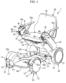
- a travel route creation system for a personal mobility vehicle (an electric mobility vehicle) 1 will be described below with reference to the accompanying drawings.
- the travel route creation system is provided with a server 100, and a controller 80 which is provided in a control unit 60 of the personal mobility vehicle 1 and which is communicable with the server 100.
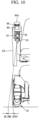
- this personal mobility vehicle 1 includes, in an example, a pair of front wheels 10, a pair of rear wheels 20, and a mobility body 30 which is supported by the front wheels (wheels) 10 and the rear wheels (wheels) 20.
- the mobility body 30 has a body 31 which is supported by the front wheels 10 and the rear wheels 20, a seat unit 40 which is attached to the body 31, and motors 50 which are attached to the mobility body 30, and which drive at least one of the pair of front wheels 10 or the pair of rear wheels 20.
- the motors 50 are attached to the body 31, and the seat unit 40 is removable from the body 31.
- the personal mobility vehicle is a mobility vehicle on which one person sits to ride on the personal mobility vehicle.
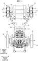
- a vehicle front-rear direction shown in Figs. 3 and 4 may be referred to as a front-rear direction in the following description, and a vehicle width direction shown in Figs. 3 and 4 may be referred to as a width direction or left-right direction in the following description.
- the vehicle front-rear direction and the front-rear direction of the mobility body 30 are identical with each other, and the vehicle width direction and the width direction of the mobility body 30 are identical with each other.
- the radial centers of the pair of front wheels 10 are arranged in the vehicle width direction
- the radial centers of the pair of rear wheels 20 are also arranged in the vehicle width direction
- the vehicle front-rear direction is orthogonal to the vehicle width direction.
- the pair of rear wheels 20 are respectively connected to the motors 50, and each of the motors 50 drives corresponding rear wheels 20.
- Driving force of the motors 50 may be transmitted to the corresponding front wheels 10 via a driving force transmitting means.
- the driving force transmitting means is a belt, gear, or the like.
- the front wheels 10 are supported by the body 31 by means of axles 11 and suspensions 12. Also, a contact surface of the front wheels 10 is formed by a plurality of rollers 13 which are arranged in a circumferential direction of the front wheels 10.
- Each of the suspensions 12 has a support member 12a and a springy member 12b which is a coil spring or the like.
- One end side of the support member 12a is supported by a front end side of the body 31, and the support member 12a can swing around a first axis line A1 extending in the vehicle width direction.
- the springy member 12b biases the other end side of the support member 12a toward the vehicle front direction.
- the axles 11 of the front wheels 10 are fixed to the support members 12a.
- a second axis line A2 which is a central axis line of the axle 11, is inclined toward the front direction with respect to a horizontal line HL, which is perpendicular to the front-rear direction.
- an angle ⁇ which is between the second axis line A2 and the horizontal line HL is 2 degrees to 15 degrees, however, the angle ⁇ may be any other angle depending on conditions.
- the pair of front wheels 10 are in a toe-in state.
- the pair of front wheels 10 are arranged so as to be parallel to each other, with the pair of front wheels 10 in the toe-in state, it is possible to increase components of force toward the vehicle rear side exerted on the axles 11 when the personal mobility vehicle 1 is moving.
- the other end of the support member 12a is movable toward the vehicle rear side with respect to the body 31 against the biasing force of the springy members 12b. Therefore, it is possible to effectively reduce vibration which is generated by collision of the rollers 13 with the contact surface.
- the front wheels 10 may not arranged in the toe-in state.
- Each of the front wheels 10 includes a hub 14 which is attached to the axles 11, and a plurality of roller supporting shafts (not shown) which are supported by the hub 14, and the plurality of rollers 13 are supported respectively by the roller supporting shafts in a rotatable manner.
- the hub 14 may be attached to the axles 11 by means of a bearing or the like, and the hub 14 may be attached to the axles 11 by means of a cushioning member, an intermediate member, or the like.
- Axis lines of the roller supporting shafts extend in directions orthogonal to the radial direction of the axle 11.
- the rollers 13 rotate around the axis line of the corresponding roller support shafts. That is to say, the front wheels 10 are omnidirectional wheels which move in every direction with respect to a travel surface.
- An outer circumferential surface of the roller 13 is formed by using a material having rubber-like elasticity, and a plurality of grooves extending in the circumferential direction thereof are provided on the outer circumferential surface of the roller 13 (refer to Figs. 5 and 6 ).
- the rear wheels 20 include an axle which is not shown, a hub 21 attached to the axle, and an outer circumferential member 22 which is provided on the outer circumferential side of the hub 21, and the outer circumferential surface thereof is formed by using a material having rubber-like elasticity, however, the omnidirectional wheels may be used as the rear wheels 20, which are the same as the front wheels 10.
- the axle of the rear wheels 20 may be the same with a main shaft of the motor 50.
- the body 31 includes a base portion 32 which extends along the ground, and a seat support portion 33 which extends toward an upper side from a rear end side of the base portion 32.
- the seat support portion 33 is inclined toward the vehicle front side, and a seat unit 40 is attached to the upper end side of the seat support portion 33.
- the base portion 32 of this embodiment includes a metallic base frame 32a which supports the suspensions 12 of the front wheels 10 and the motors 50 of the rear wheels 20, and a plastic cover portion 32b which at least partially covers the base frame 32a.
- the cover portion 32b is used as a portion for putting feet of a driver seated on the seat unit 40, a portion for placing a luggage, or the like.
- the cover portion 32b also includes a pair of fenders 32c each of which covers the corresponding front wheels 10 from the upper side.
- the fenders 32c only have a function which covers the front wheels 10.
- the fenders 32c also have a function which strengthens rigidity of the body 31. Also, there may be a case where each of the fenders 32c covers only a part of the front wheels 10.
- the seat unit 40 has a shaft 40a at the lower portion thereof, and the shaft 40a is attached to the upper end side of the seat support portion 33.
- a rechargeable battery BA is provided at the back surface of the seat support portion 33, and a control unit 60, which will be described below, is placed within the seat support portion 33.
- the seat unit 40 has a seat surface portion 41 on which a driver is seated, a backrest portion 42, a right control arm 43, and a left control arm 43.
- An armrest 43a is fixed to the upper surface of each of the control arms 43.
- the driver puts the arms on the armrests 43a of the pair of the control arms 43, respectively.
- the driver puts the arms on the upper ends of the pair of control arms 43, respectively.
- both of the control arms 43 and the armrests 43a are provided, however, the control arms 43 or the armrests 43a may only be provided. In this case, the driver puts at least one of the arms and the hands on the control arms 43, or puts at least one of the arms and the hands on the armrests 43a.
- An operation portion 44 having an operation lever 44a is provided at the upper end of the right control arm 43.
- the operation lever 44a is positioned at a neutral position by a springy member (not shown) which is located within the operation portion 44.
- the driver can displace the operation lever 44a toward the right direction, the left direction, the front direction, and the rear direction with respect to the neutral position.
- the control unit 60 controls the motors 50 in response to the received signal.
- a signal which makes the motors 50 rotate toward the vehicle front side is sent.
- the personal mobility vehicle 1 moves forward at speed which is in response to the displacement amount of the operation lever 44a.
- a signal which makes the left motor 50 rotate toward the vehicle front side at speed which is slower than the right motor 50.
- the personal mobility vehicle 1 moves forward while turning left at speed which is in response to the displacement amount of the lever 44a.
- a setting portion 45 which is for performing all sorts of settings related to the personal mobility vehicle 1 is provided at the upper end of the left control arm 43.
- Examples of the various sorts of settings are settings of maximum speed, settings regarding a driving mode, and settings for locking the personal mobility vehicle 1.
- a plurality of operation buttons, a display, and the like are provided at the setting portion 45.
- Examples of the driving mode are an energy saving driving mode in which power consumption is suppressed, a sports driving mode in which running performance is enhanced and in which the electric consumption is not suppressed, a normal driving mode which is a mode between the energy saving driving mode and the sports driving mode, and the like.
- Examples of the settings for locking the personal mobility vehicle 1 are a setting of passcode for locking, a setting of timing for unlocking, and the like.
- the setting signal of the setting portion 45 is sent to the control unit 60, which will be described below, and the settings of the personal mobility vehicle 1 is set or changed in the control unit 60.
- a notification device 46 is provided in each of the left and the right control arms 43.
- the notification device 46 is a voice generator, a display, a vibration generation device, or the like.
- the vibration generation device vibrates a part of the upper end side of the control arm 43, the operation portion 44, the setting portion 45, and the like, at several tens of Hz for example.
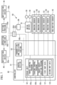
- control unit 60 has a motor driver 70 which drives the motors 50, and a controller 80.
- the motor driver 70 is connected to the battery BA. Also, the motor driver 70 is connected to each of the motors 50 as well, and the motor driver 70 supplies drive power to the motors 50.
- the controller 80 includes a control section 81 having a CPU, a RAM, and the like, a storage unit 82 having a non-volatile storage, a ROM, and the like, and a transmitting and receiving portion 83.
- a travel control program 82a which controls the personal mobility vehicle 1 is stored in the storage unit 82.
- the control section 81 operates on the basis of the travel control program 82a, and sends drive signals for driving the motors 50 to the motor driver 70 in accordance with the signals from the operation portion 44 and the setting portion 45.
- the signal from the operation portion 44 and that from the setting portion 45 are sent to the controller 80 via signal lines 80a and signal lines 80b. Also, a control signal from the controller 80 is sent to the notification devices 46 via the signal lines 80a and the signal lines 80b.
- the signal lines 80a are provided in the seat unit 40, and the signal line 80b is provided in the body 31. Connectors 80d, 80e are provided between the signal lines 80a and the signal line 80b.
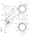
- Each of two stereo cameras (sensors) 90 which is a visual sensor, is attached to the upper end side of the right control arm 43 and the upper end side of the left control arm 43.
- Each of the stereo cameras 90 includes a pair lens units 91 and a camera main body 92 which supports the pair of the lens units 91.
- a pair of imaging sensors 93 ( Fig. 7 ) is provided inside the camera main body 92, and the pair of the imaging sensors 93 correspond to the pair of lens units 91, respectively.
- the imaging sensors 93 are known sensors, such as a CMOS sensor, or the like.
- the imaging sensors 93 are connected to the controller 80.
- At least a part of the left front wheel 10, or a part of the fender 32c of the left front wheel 10 is positioned within a detection area DA of the stereo camera 90 provided at the left control arm 43. Also, an area at the outside in the width direction with respect to the left front wheel is positioned within this detection area DA.
- the right front wheel 10 is positioned within the detection area DA of the stereo camera 90 provided at the right control arm 43. Also, an area at the outside in the width direction with respect to the right front wheel 10 is positioned within this detection area DA.
- the detection area DA of the stereo camera 90 is an area where the image caption areas of the imaging sensors 93 are overlapped. It is intended that the detection area DA includes the outside area of the front wheel 10 in the width direction.
- a light axis LA of each the lens units 91 of the stereo camera 90 extends diagonally toward the outside in the width direction. More specifically, in a plan view shown in Fig. 9 , the light axis LA of each of the lens units 91 extends in a direction forming an angle ⁇ with respect to the front-rear direction. In one example, the angle ⁇ is 5 degrees to 30 degrees.
- the control section 81 of the controller 80 operates on the basis of an evading control program 82b which is stored in the storage unit 82. That is to say, the control section 81 creates distance images by processing the parallax images. And, the control section 81 detects the object to be avoided with which the front wheels 10 or the fenders 32c may come into contact.
- the target to be avoided is an obstacle, a person, an animal, a plant, and the like, for example. And, the obstacle is a wall, a large rock, a bump, and the like, for example.
- the control section 81 detects the object to be avoided, such as a bump, a hole, a gutter, or the like, which the front wheels 10 may collides against, be fallen in, or get caught in, in the distance images.
- control section 81 controls the motors 50 by control signals for evading operation when the object to be avoided with which the wheels 10 or the fenders 32c may come into contact in a predetermined area AR1 is detected in a predetermined area AR1 in the detection area DA, for example. Also, the control section 81 controls the motors by control signals for evading operation when the control section 81 detects the object to be avoided in which the front wheels 10 may be fallen or get caught in the predetermined area AR1 in the detection area DA, for example. Examples of the evading operation include reduction of the rotation speed of the motors 50, stopping the rotation of the motors 50, controlling the motors 50 for restricting the movement of the personal mobility vehicle 1 toward the side of the object to be avoided, and the like.
- the travel surface at the outer side in the width direction of each of the front wheels 10 is positioned within the detection area DA of the stereo camera 90. More preferably, at least either a part of the front wheel 10 or a part of the fender 32c of the front wheel 10 should be positioned within the detection area DA of the stereo camera 90.
- a bump or a slope is present at the outer side in the width direction of the front wheel 10
- this configuration is advantageous in perceiving the relationship between the direction in which the mobility body 30 is oriented and the bump or the slope.
- the driver in order for the driver to visually check the vicinity of the front wheel 10 on the travel surface at the outer side in the width direction of the front wheel 10, the driver needs to change his/her orientation.
- the vicinity of the front wheel 10 on the travel surface at the outer side in the width direction of the front wheel 10 is positioned within the detection area DA of the stereo camera 90, the burden on the driver for monitoring the vicinity is reduced.
- the driver when the personal mobility vehicle 1 is run in a house or an office, the driver needs to take care not to come into contact with objects to be avoided, such as furniture, walls, and the like.
- the driver needs to be careful of the angle, speed, and the like at which he/she accesses an object, such as stairs, a slope, and the like.
- Various kinds of objects are present in a house or an office. For this reason, it is difficult for the driver to reliably perceive all of these objects by a visual check. Therefore, the configuration of this embodiment is extremely useful in a house and an office.
- each of the stereo cameras 90 is attached to the corresponding control arm 43.
- the control arm 43 is a portion on which the hand and the arm of the driver are placed.
- Each of the control arms 43 is typically disposed at the outer side in the width direction with respect to the waist of the driver seated on the seat unit 40.
- each of the control arms 43 is typically disposed at the outer side in the width direction with respect to the corresponding thigh of the driver seated on the seat unit 40.
- the seat unit 40 can be provided with a pair of arm rests 43a, instead of the pair of control arms 43.
- each of the stereo cameras 90 can be provided on the front end portion of the corresponding arm rest 43a. This configuration also affords the same advantageous effect as the present embodiment.
- stereo camera 90 can also be attached to a pole extending from the seat unit 40 or the mobility body 30, the seat unit 40, or the like.
- the driver can easily make visual identification of the positions of his/her hands and the positions of his/her arms.
- the driver can intuitively recognize the rough positions of his/her hands and the rough positions of his/her arms.
- the configuration of this embodiment in which the stereo cameras 90 are provided on the control arms 43 or the arm rests 43a, is advantageous in preventing collisions of the stereo cameras 90 against a wall, or the like.
- the configuration of this embodiment is advantageous in preventing damage to the stereo cameras 90, positional shifting of the stereo cameras 90, and the like.
- the light axis LA of each of the lens units 91 of each of the stereo cameras 90 extends obliquely towards the outer side in the width direction. For this reason, a wider area at the outer side in the width direction of the front wheel 10 is positioned within the detection area DA of the stereo camera 90. This configuration is extremely useful in reliably perceiving the relationship between the front wheel 10 and objects that are present at the outer side in the width direction of the front wheel 10.
- a 3D area sensor has a well-known structure in which each of the plurality of image sensors arranged on a flat surface obtains distance information.
- the well-known TOF method or the like can be used to obtain the distance information of each pixel.
- a laser sensor or an ultrasonic sensor can also be used instead of each of the stereo cameras 90.
- a millimeter wave sensor which uses electromagnetic waves with a wavelength of 1-1000 mm, instead of the stereo camera 90.
- a millimeter wave sensor which uses electromagnetic waves with a wavelength of 1-1000 mm, instead of the stereo camera 90.
- LiDAR Laser Imaging Detection and Ranging
- each of the stereo cameras 90 may be disposed in the interior of an upper end portion of the corresponding control arm 43.
- the stereo camera 90 is disposed in a hollow portion provided in the control arm 43.
- a transparent cover is attached to the front surface of the upper end portion of the control arm 43, and the pair of lens units 91 are disposed at the inner side with respect to the cover.
- an area in front of the personal mobility vehicle 1 is positioned within the detection area DA of each of the stereo cameras 90 in this embodiment.
- the area in front of the head of the driver is positioned within the detection area DA of the stereo camera 90.
- each of the front wheels 10 has a hub and an outer circumferential member 15 that is provided on the outer circumference of the hub and that has rubber-like elasticity.
- Each of the rear wheels 20 shown in Fig. 11 is an omnidirectional wheel having an axle, a plurality of rollers, and a hub similar to the above-described axle 11, rollers 13, and hub 14, respectively, and is supported on a rear end side of the body 31 with a suspension similar to the suspension 12 interposed therebetween.
- the motor 50 may be supported on the base frame 32a in the vicinity of each of the pair of front wheels 10, and each of the front wheels 10 may be driven by the corresponding motor 50.
- This embodiment may be configured so that the rear wheels 20 are driven by the motors 50, or alternatively, so that wheels other than the front wheels 10 and the rear wheels 20 are driven by the motors 50.
- the antenna or substrate of the right millimeter wave sensor can be oriented obliquely downward and obliquely outward (rightward), and the antenna or substrate of the left millimeter wave sensor can be oriented obliquely downward and obliquely outward (leftward).
- This arrangement is useful in improving the detection accuracy of an area at the outer side in the vehicle width direction of the corresponding front wheel 10 or rear wheel 20.
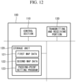
- the server 100 includes: a control section 110 having a CPU, a RAM, and the like; a storage unit 120 having a non-volatile memory, a ROM, and the like; and a transmitting and receiving portion 130.
- the storage unit 120 stores first map data 121 indicating areas in which the personal mobility vehicle 1 can travel and second map data 122 having information about safety while the personal mobility vehicle 1 is traveling or is at a standstill.
- the storage unit 120 stores a passing-point setting program 123 for setting a plurality of passing points spaced apart from one another between the current position of the personal mobility vehicle 1 and a destination.
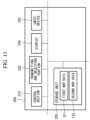
- a terminal device 200 such as a tablet computer or a smartphone, is provided on the personal mobility vehicle 1 side.
- the terminal device 200 includes: a control section 210 having a CPU, a RAM, and the like; a storage unit 220 having a non-volatile memory, a ROM, and the like; a transmitting and receiving portion 230; a display 240; and an input device 250, such as a touch screen or an input key.
- the terminal device 200 and the controller 80 store the first map data 121 received from the server 100 or another computer. Note that the controller 80, the server 100, and the terminal device 200 can communicate with one another.
- the terminal device 200 is owned by, for example, the rider of the personal mobility vehicle 1, a person related to the rider, or the like.
- the terminal device 200 may be supported on the personal mobility vehicle 1 by using a predetermined support device.
- the controller 80 stores the second map data 122 received from the server 100 or another computer.
- the terminal device 200 may store the second map data 122 received from the server 100 or another computer.
- the first map data 121 and the second map data 122 may be stored in the terminal device 200 and the controller 80 by using a medium, such as a DVD-ROM.
- the first map data 121 includes map information on the interiors of buildings, the interiors of station premises, and outdoor areas.
- the map information on the interior of buildings and the interior of station premises includes information on objects such as pathways, rooms, doors, entrance doors, walls, columns, stairs, elevators, and escalators.
- the map information on outdoor areas includes information on roads, sidewalks, stairs, buildings, rivers, ponds, the sea, non-paved areas, and the like.
- Non-paved areas include bush areas, grassy field areas, lawn areas, gravel areas such as dirt roads, sand areas such as sandy beaches, and the like.
- Fig. 14 shows an example of the first map data 121.
- the personal mobility vehicle 1 cannot travel in the hatched areas, whereas the personal mobility vehicle 1 can travel in areas other than the hatched areas. Note that grassy field areas, lawn areas, gravel areas, sandy beaches, and the like can be included in areas in which the personal mobility vehicle 1 can travel.
- the second map data 122 is a map indicating a bump 122a and slopes 122b over which the personal mobility vehicle 1 can safely travel.
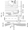
- Fig. 15 is a map formed by superimposing the second map data 122 on the first map data 121 in Fig. 14 .
- Drawn image elements in individual map data are associated with position data thereon.
- the map formed as a result of superimposing the second map data 122 on the first map data 121 may be displayed on the display 240 of the terminal device 200, a display connected to the controller 80, or the like. In this case, as shown in Fig.
- the height of the bump 122a, a travel difficulty level index 122c indicating the difficulty for traveling over the bump 122a, and the like may be shown in the vicinity of the bump 122a over which the personal mobility vehicle 1 can travel.
- the gradient of a slope 122b, the height difference of the slope 122b, a travel difficulty level index 122d related to the difficulty for traveling over the slope 122b, and the like may be shown in the vicinity of the slope 122b.
- a tilt direction index 122e indicating the direction of a slope 122b may be shown on or near the slope 122b.
- the second map data 122 includes the travel difficulty level indexes 122c, 122d and also includes the tilt direction index 122e.
- the travel difficulty level index 122d may be shown by the size, the length, the color, or the like of an arrow.
- the server 100 receives, from the terminal device 200, information on the current position of the personal mobility vehicle 1 and information on a destination.
- the server 100 may receive, from the controller 80, information on the current position and information on a destination based on input to the setting portion 45.
- the information on the current position may be based on information input to the terminal device 200 by the operator of the terminal device 200.
- the operator inputs, to the terminal device 200, information that can identify the position at which the personal mobility vehicle 1 is disposed, such as a building name, a room number, and a floor number.
- the operator may input an arbitrary position on the first map data 121 displayed on the display 240 by using a pointer, a touch screen function, or the like.
- the information based on the identified position is transmitted from the terminal device 200 to the server 100.
- the control section 81 of the controller 80 performs well-known current position estimation by using a Global Navigation Satellite System (GNSS) receiver, an odometer, the stereo cameras 90, or the like provided on the personal mobility vehicle 1
- the estimated position may be transmitted from the controller 80 to the server 100 as the information on the current position.
- the information on the current position is based on input performed by the operator
- the information on the current position can be set easily, whereby setting of the current position becomes reliable in many cases.
- the capacity of the battery BA of the personal mobility vehicle 1 is strictly limited, it is more preferable in reducing the power consumption of the battery BA to set the information on the current position on the basis of input performed by the operator.
- the current position is a location in a room of a building
- the destination is a location in a park.
- the control section 110 of the server 100 sets a plurality of passing points P between the current position and the destination on the basis of the passing-point setting program 123 and transmits, to the controller 80, information on the passing points P that have been set.
- the information on the passing points P that have been set may be transmitted to the terminal device 200.
- the controller 80 the series of passing points P shown in Fig. 16 are set on a map including the first map data 121 and the second map data.
- Information on the passing points P is, for example, the position information about each of the passing points P on the first map data 121.
- the control section 81 of the controller 80 creates travel routes between the plurality of passing points P so as to pass, one after another, the plurality of passing points P or the vicinity thereof, on the basis of a travel-route creation program 82c stored in the storage unit 82. More specifically, the control section 81 creates a travel route up to the next passing point (the next passing point which the personal mobility vehicle 1 should pass) P by using data obtained by sensors such as the stereo cameras 90, the first map data 121, and the second map data 122.
- the control section 81 when arriving at the next passing point P or the vicinity thereof, the control section 81 further creates a travel route up to the next passing point P by using the data obtained by sensors such as the stereo cameras 90, the first map data 121, and the second map data 122.
- the personal mobility vehicle 1 enters the autonomous driving mode on the basis of, for example, an input to the input device 250 of the terminal device 200 or an input to the setting portion 45.
- each of the passing points P may include information on the direction in which the personal mobility vehicle 1 should be oriented (arrangement information). In this case, a created travel route is used to make the direction of the personal mobility vehicle 1 coincide with the arrangement information included in the next passing point P when the personal mobility vehicle 1 reaches the next passing point P.
- the control section 81 of the controller 80 transmits drive signals for driving each of the motors 50 to the motor driver 70, thereby causing the personal mobility vehicle 1 to follow the created travel route.
- the travel route may be displayed on the display 240 of the terminal device 200, and also the position of the personal mobility vehicle 1 obtained moment by moment by using well-known current position estimation technology may be displayed on the display 240.
- the word "vicinity" means that, for example, the distance from the personal mobility vehicle 1 to a passing point P is less than or equal to a reference distance (several meters in one example).
- the passing points P may be set every several meters or may be set every 10-20 meters. These examples are not meant to limit the passing points P from being set at intervals of larger distances.
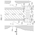
- the control section 81 sets the angle at which the personal mobility vehicle 1 enters the bump 122a within an angle range from 45° to 90°, in which 45° and 90° are included, in this travel route.
- a travel route is created between two passing points P, as shown in Fig. 17 by a broken line DL1.
- another travel route is created between two passing points P, as shown in Fig. 17 by a broken line DL2.
- the angle at which the personal mobility vehicle 1 enters the slope 122b is within the angle range from 45° to 90° in which 45° and 90° are included.
- the angle at which the personal mobility vehicle 1 enters the bump 122a is within the angle range from 45° to 90° in which 45° and 90° are included.
- the front wheels 10 or the rear wheels 20 are omnidirectional wheels. For this reason, the personal mobility vehicle 1 can change the direction thereof at that point without having to move forward or backward. For this reason, positions just before the bump 122a and the slope 122b in a travel route created by the control section 81 may include accompanying information about the direction in which the personal mobility vehicle 1 should be oriented at those positions. This accompanying information constitutes a part of the created travel route, and the personal mobility vehicle 1 changes its direction according to this accompanying information.
- the controller 80 of the personal mobility vehicle 1 controls each of the motors 50 via the motor driver 70 by using detection results of sensors such as the stereo cameras 90 so that the access angle is within the above-described angle range.
- the controller 80 should control each of the motors 50 by using the detection results of sensors such as the stereo cameras 90 so that the access angle is within the above-described angle range.
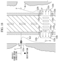
- passing points P are set just before the bump 122a and the slope 122b in the example shown in Fig. 17 , passing points P may be set beyond the bump 122a and the slope 122b, as shown in Fig. 18 .
- the control section 210 sets the angle at which the personal mobility vehicle 1 enters the bump 122a and the slope 122b within the angle range from 45° to 90° in which 45° and 90° are included.
- the angle at which the personal mobility vehicle 1 enters the bump 122a or the slope 122b may be preferably set within the angle range from 45° to 85° in which 45° and 85° are included in some cases in order to mitigate the impact produced when the personal mobility vehicle 1 enters the bump 122a or the slope 122b.
- the access angle is an acute angle ⁇ between the vehicle front-rear direction of the personal mobility vehicle 1 and the extension direction of the bump 122a or the angle between the vehicle front-rear direction of the personal mobility vehicle 1 and the extension direction of the edge line of the slope 122b.
- control section 81 creates, as a part of a travel route, information on the orientation of the personal mobility vehicle 1 (direction in which the personal mobility vehicle 1 is oriented) at the time the personal mobility vehicle 1 stops in each of the slopes 122b.
- control section 81 creates orientation information of the personal mobility vehicle 1 so that the angle formed between the orientation of the arrow of the tilt direction index 122e and the vehicle front-rear direction of the personal mobility vehicle 1 is set within an angle range of 45° or less in which 45° is included.
- the control section 81 of the controller 80 transmits, to the motor driver 70, drive signals for driving each of the motors 50, thereby causing the orientation of the personal mobility vehicle 1 to be an orientation in accordance with the orientation information included in the travel route.
- the above-described angle should preferably be an angle that can prevent such an unintentional movement.
- the front wheels 10 or the rear wheels 20 of the personal mobility vehicle 1 in this embodiment are omnidirectional wheels.
- the central axis line of the axle 11 of each of the omnidirectional wheels coincides with the tilt direction of a slope 122b, the omnidirectional wheels unintentionally move downward on the slope 122b.
- the above-described configuration capable of preventing such a movement is advantageous in improving the safety of the rider of the personal mobility vehicle 1 and people around the vehicle.
- any of the controller 80, the server 100, and the terminal device 200 may receive travel area reference information on the basis of input performed by the operator or the rider and may change, in the first map data 121, areas in which the personal mobility vehicle 1 can travel according to the received travel area reference information.
- the operator or the rider inputs a setting value of the travel area reference information to the setting portion 45 or the input device 250 of the terminal device 200.
- a setting value placing importance on safety is input, a new untravelable area is added to the first map data 121.
- the width of an untravelable area in the vicinity of the roadway is increased.
- Data on the newly added untravelable area may be included in the second map data 122. This realizes autonomous running which further matches a demand from the rider.
- a travel fatigue index may be associated with each partial area in a travelable area.
- the travel fatigue index relates to an irregularity state of the travel surface, a level of slipperiness of the travel surface, and the like.
- any of the controller 80, the server 100, and the terminal device 200 receives a request related to travel fatigue on the basis of input performed by the operator or the rider.
- the control section 110 of the server 100 sets a plurality of passing points according to the above-described request with reference to the travel fatigue index of each of the partial areas.
- the control section 81 of the controller 80 may create a travel route according to the above-described request, referring to the travel fatigue index of each of the partial areas. This realizes autonomous running according to the state of the rider.
- the control section 110 sets passing points by taking into account placing importance on a reduction in the travel time, and accordingly, the control section 81 also creates travel routes by taking into account placing importance on a reduction in the travel time.
- the control section 110 sets passing points for avoiding these severe meteorological conditions, and accordingly, the control section 81 creates travel routes for avoiding these severe meteorological conditions.
- any of the controller 80, the server 100, and the terminal device 200 may receive, on the basis of input performed by the operator or the rider, evaluation scores of bumps, slopes, and the like in the first map data 121 or the second map data 122.
- the terminal device 200 displays a selected bump 122a or slope 122b together with choices of evaluation scores on the display 240.
- the bump 122a or the slope 122b disposed closest to the personal mobility vehicle 1 may be displayed as the selected bump 122a or slope 122b on the display 240, or alternatively, a bump 122a or a slope 122b may be selected on the basis of input performed by the operator or the rider.
- the selected evaluation score is transmitted to the server 100 together with information on the corresponding bump 122a or slope 122b.
- the control section 110 of the server 100 accumulates the received evaluation score in the storage unit 120, determines the travel difficulty level indexes 122c and 122d of the bumps 122a and the slopes 122b on the basis of the accumulated evaluation score, and reflects the determined travel difficulty level indexes 122c and 122d on the second map data 122.
- the personal mobility vehicle 1 may be provided with a well-known inclination sensor 95 ( Fig. 7 ).
- the controller 80 receives a measurement value of the inclination sensor 95.
- the controller 80 transmits, to the server 100, the received measurement value which is associated with the current position that has been estimated by using the GNSS receiver, odometer, stereo cameras 90, or the like.
- the control section 110 of the server 100 accumulates the received measurement value in the storage unit 120 as an evaluation score, determines a travel difficulty level index 122d of each of the slopes 122b on the basis of the accumulated evaluation score, and reflects the determined travel difficulty level index 122d on the second map data 122.
- any of the controller 80, the server 100, and the terminal device 200 may receive an evaluation score of a people congestion level in each of the travelable areas (how heavily the area is crowded) on the first map data 121.
- the terminal device 200 displays, on the display 240 thereof, a selected partial area in a travelable area together with choices of evaluation scores.
- the partial area disposed closest to the personal mobility vehicle 1 may be selected, or alternatively, a partial area may be selected on the basis of input performed by the operator or the rider.
- the selected evaluation score is transmitted to the server 100 together with information on the corresponding partial area.
- the control section 110 of the server 100 accumulates the received evaluation score in the storage unit 120, determines a travel difficulty level index of each of the partial areas on the basis of the accumulated evaluation score, and reflects the determined travel difficulty level index on the second map data 122.
- any of the controller 80, the server 100, and the terminal device 200 may receive evaluation scores of travel difficulty level in buildings, facilities, and shops on the first map data 121 on the basis of input performed by the operator or the rider.
- the terminal device 200 displays, on the display 240 thereof, a selected building, facility, or shop together with choices of evaluation scores.
- the building, facility, or shop disposed closest to the personal mobility vehicle 1 may be selected, or alternatively, a building, a facility, or a shop may be selected on the basis of input performed by the operator or the rider.
- the selected evaluation score is transmitted to the server 100 together with information on the corresponding building, facility, or shop.
- the control section 110 of the server 100 accumulates the received evaluation score in the storage unit 120, determines a travel difficulty level index of each of the buildings, facilities, and shops on the basis of the accumulated evaluation score, and reflects the determined travel difficulty level index on the second map data 122.
- the terminal device 200 may display choices of attributes of the rider on the display 240 thereof.
- the attributes include the age of the rider, the condition of the rider, and the like.
- the server 100 can accumulate, in the storage unit 120, the received evaluation scores, classified by attribute, and can create a plurality of items of second map data 122 corresponding to the plurality of respective attributes.
- the plurality of items of second map data 122 have different travel difficulty level indices 122c and 122d.
- the terminal device 200 may be responsible for some or all of the above-described functions of the controller 80.
- the control section 210 of the terminal device 200 may set a travel route between passing points P. In this manner, a control section of another computer device can execute some or all of the above-described functions of the controller 80.
- control section 81 creates travel routes for the personal mobility vehicle 1 on the basis of the first map data 121 indicating areas in which the personal mobility vehicle 1 can travel and the second map data 122 having information about safety while the personal mobility vehicle 1 is traveling or is at a standstill.
- the first map data 121 includes data on the positions and areas of sidewalks, the interiors of buildings, the interiors of station premises, open spaces, parks, and the like
- the second map data 122 includes information about bumps, slopes, and the like that are present on sidewalks, in buildings, in station premises, in open spaces, in parks, and the like.
- travel routes are set by taking into account safety while the personal mobility vehicle 1 is traveling or is at a standstill.
- first map data 121 having almost all of the positions and areas of sidewalks, interiors of buildings, interiors of station premises, open spaces, parks, and the like.
- the positions and areas of sidewalks, interiors of buildings, interiors of station premises, open spaces, parks, and the like are not changed so often, and therefore, once the first map data 121 is created, the update frequency thereof is not so high.
- second map data 122 including almost all information about safety while the personal mobility vehicle 1 is traveling or is at a standstill.
- the first map data 121 has detailed shape information, position information, and the like of each element, and thus it often takes a long time to add data to the first map data 121.
- the second map data 122 which has, for example, a simple data structure different from that of the first map data 121. Therefore, it is possible to update the second map data 122 moment by moment, which makes it possible to set travel routes in accordance with a request from the rider of the personal mobility vehicle 1.
- the travel route creation system includes: the server 100 for setting a plurality of passing points P spaced apart from one another between the current position of the personal mobility vehicle 1 and a destination at least on the basis of the first map data 121 indicating areas in which the personal mobility vehicle 1 can travel, information on the current position of the personal mobility vehicle 1, and information on the destination; the sensors provided in the personal mobility vehicle 1; and the control sections 81 and 210 that receive information on the plurality of passing points P from the server 100 and that create travel routes between the plurality of passing points P by using data obtained with the sensors so as to pass, one after another, the passing points P or the vicinities thereof.
- the control sections 81 and 210 create travel routes between the plurality of passing points P. In short, if a travel route up to the next passing point P has been created, the personal mobility vehicle 1 can arrive at that passing point P or the vicinity thereof. More specifically, even in the case where it becomes necessary to change a travel route for the personal mobility vehicle 1 according to the presence, motion, and the like of other objects including people and bicycles, the control sections 81 and 210 just need to change the travel route up to the next passing point P. Therefore, power consumption due to moment-by-moment changes of travel routes can be reduced.
- control sections 81 and 210 are operated with the battery BA of the personal mobility vehicle 1, the power consumption of the battery BA of the personal mobility vehicle 1 is reduced, and also in the case where the control section 210 is a tablet computer or the like, the power consumption of the battery BA is reduced. This will make the rider more comfortable.
- the control sections 81 and 210 when the control sections 81 and 210 create a travel route that allows the personal mobility vehicle 1 to pass via the bump 122a or a slope 122b on the basis of the second map data 122 indicating the bump 122a or the slope 122b over which the personal mobility vehicle 1 can travel, the control sections 81 and 210 create a travel route in which the angle of access to the bump 122a or the slope 122b is be 45° or more.
- the front wheels 10 or the rear wheels 20 of the personal mobility vehicle 1 are omnidirectional wheels, if the access angle, i.e., the acute angle ⁇ between the vehicle front-rear direction of the personal mobility vehicle and the extension direction of a bump, or the like is small, the personal mobility vehicle 1 readily moves in an unintended direction at the time the omnidirectional wheels access the bump.
- the front wheels 10 or the rear wheels 20 of the personal mobility vehicle 1 are other types of wheels, a similar phenomenon may also occur.
- the control sections 81 and 210 create a travel route that causes the angle at which the personal mobility vehicle 1 enters the bump 122a or the slope 122b to be 45° or more. For this reason, it is possible to suppress unintended movement of the personal mobility vehicle 1 when the personal mobility vehicle 1 enters a bump or a slope, which makes the rider more comfortable.
- the access angle should preferably be 60° or more.
- control sections 81 and 210 create a travel route that sets the angle at which the personal mobility vehicle 1 enters the bump 122a within an angle range of 85° or less.
- the angle at which the personal mobility vehicle 1 enters the bump 122a is 90°
- the impact applied to the personal mobility vehicle 1 may be large in some cases in accordance with the specifications of the personal mobility vehicle 1, the state of the bump 122a, or the like.
- the angle at which the personal mobility vehicle 1 enters the bump 122a is 85° or less, which can make the rider more comfortable.
- the personal mobility vehicle 1 includes sensors having the detection areas DA which cover areas at the outer sides in the width direction of the front wheels 10, and the control sections 81 and 210 control the personal mobility vehicle 1 by using detection results of the sensors so that the angle at which the personal mobility vehicle 1 enters the bump 122a or the slope 122b is 45° or more.
- the relationship between the bump 122a or the slope 122b and the front wheels 10 can be perceived on the basis of the detection results of the sensors. For this reason, the access angle at which the front wheels 10 access the bump 122a or the slope 122b can be reliably set to 45° or more.
- the front wheels 10 or the rear wheels 20 are omnidirectional wheels.
- an omnidirectional wheel may move in the width direction more than expected in some cases.
- the capability of reliably perceiving the relationship between the front wheels 10 or the rear wheels 20, which are omnidirectional wheels, and objects that are present in areas at the outer sides in the width direction of the front wheels 10 or the rear wheels 20 is advantageous in controlling the angle at which the front wheels 10 and the rear wheels 20 enters the objects.
Landscapes
- Engineering & Computer Science (AREA)
- Radar, Positioning & Navigation (AREA)
- Remote Sensing (AREA)
- Automation & Control Theory (AREA)
- Physics & Mathematics (AREA)
- General Physics & Mathematics (AREA)
- Aviation & Aerospace Engineering (AREA)
- Public Health (AREA)
- Animal Behavior & Ethology (AREA)
- General Health & Medical Sciences (AREA)
- Life Sciences & Earth Sciences (AREA)
- Veterinary Medicine (AREA)
- Health & Medical Sciences (AREA)
- Transportation (AREA)
- Mathematical Physics (AREA)
- Mechanical Engineering (AREA)
- Traffic Control Systems (AREA)
- Motorcycle And Bicycle Frame (AREA)
- Navigation (AREA)
- Electric Propulsion And Braking For Vehicles (AREA)
- Control Of Position, Course, Altitude, Or Attitude Of Moving Bodies (AREA)
Applications Claiming Priority (2)
| Application Number | Priority Date | Filing Date | Title |
|---|---|---|---|
| JP2018169678 | 2018-09-11 | ||
| PCT/JP2019/035585 WO2020054733A1 (ja) | 2018-09-11 | 2019-09-10 | 走行ルート作成システム |
Publications (3)
| Publication Number | Publication Date |
|---|---|
| EP3851800A1 EP3851800A1 (en) | 2021-07-21 |
| EP3851800A4 EP3851800A4 (en) | 2022-06-08 |
| EP3851800B1 true EP3851800B1 (en) | 2025-05-21 |
Family
ID=69778108
Family Applications (1)
| Application Number | Title | Priority Date | Filing Date |
|---|---|---|---|
| EP19860371.4A Active EP3851800B1 (en) | 2018-09-11 | 2019-09-10 | Travel route creation system |
Country Status (5)
| Country | Link |
|---|---|
| US (1) | US11983022B2 (enExample) |
| EP (1) | EP3851800B1 (enExample) |
| JP (1) | JP7477877B2 (enExample) |
| CN (1) | CN112236647B (enExample) |
| WO (1) | WO2020054733A1 (enExample) |
Families Citing this family (11)
| Publication number | Priority date | Publication date | Assignee | Title |
|---|---|---|---|---|
| DE102019003430B3 (de) * | 2019-05-15 | 2020-06-04 | Daimler Ag | Verfahren zur Durchführung eines automatisierten oder autonomen Fahrbetriebs eines Fahrzeugs |
| JP2021030953A (ja) * | 2019-08-27 | 2021-03-01 | スズキ株式会社 | 電動車両 |
| US11863007B1 (en) * | 2019-12-11 | 2024-01-02 | Amazon Technologies, Inc. | Wheel-based charger for wireless smart controllers and carts |
| US12077229B2 (en) * | 2020-04-22 | 2024-09-03 | Boston Dynamics, Inc. | Stair tracking for modeled and perceived terrain |
| US11191597B1 (en) * | 2020-04-28 | 2021-12-07 | Arya Sasikumar | Robotic medical assistant vehicle and interface |
| US20230192101A1 (en) * | 2020-05-20 | 2023-06-22 | Irider | Vehicle assistive system |
| JP7409278B2 (ja) * | 2020-10-06 | 2024-01-09 | トヨタ自動車株式会社 | 全方向性ホイール搭載車両 |
| WO2022145036A1 (ja) * | 2020-12-29 | 2022-07-07 | 三菱電機株式会社 | 経路生成装置、経路生成方法及び経路生成プログラム |
| JP7468473B2 (ja) * | 2021-07-08 | 2024-04-16 | トヨタ自動車株式会社 | 情報処理装置、情報処理方法、及び端末装置 |
| JP7468474B2 (ja) * | 2021-07-08 | 2024-04-16 | トヨタ自動車株式会社 | 情報処理装置、情報処理方法、及び端末装置 |
| JP2023177051A (ja) * | 2022-06-01 | 2023-12-13 | スズキ株式会社 | 小型電動車両の運用システム |
Family Cites Families (43)
| Publication number | Priority date | Publication date | Assignee | Title |
|---|---|---|---|---|
| GB1066428A (en) * | 1966-03-01 | 1967-04-26 | Rodvinon Ivanovitch Zamotin | Wheel chair |
| GB2156287B (en) * | 1984-03-29 | 1987-11-04 | Everaids Limited | Wheeled vehicle able to climb obstacles |
| JPH0630807U (ja) * | 1992-09-22 | 1994-04-22 | 株式会社明電舎 | 無人搬送車の制御装置 |
| JP3700508B2 (ja) | 1999-12-17 | 2005-09-28 | 三菱自動車工業株式会社 | 走行路判別装置 |
| JP3488200B2 (ja) | 2000-12-20 | 2004-01-19 | 株式会社サントップテクノ | 走行型路面形状測定装置 |
| JP4575620B2 (ja) | 2001-05-17 | 2010-11-04 | 東北電力株式会社 | 車両自動搬送システム |
| JP2003010257A (ja) * | 2001-07-04 | 2003-01-14 | Matsushita Electric Ind Co Ltd | 経路情報収集車椅子 |
| US6857490B2 (en) * | 2001-12-11 | 2005-02-22 | Robert T. Quigg | Stair-climbing wheelchair |
| JP2003245310A (ja) * | 2002-02-26 | 2003-09-02 | Honda Motor Co Ltd | 低速移動車両および低速移動車両地理案内システム |
| JP3697454B1 (ja) * | 2005-01-14 | 2005-09-21 | インコムジャパン有限会社 | 個人の身体特性に応じた経路案内システム |
| JP2006263104A (ja) * | 2005-03-23 | 2006-10-05 | Kenji Kubota | 電動車椅子 |
| JP2007155504A (ja) * | 2005-12-05 | 2007-06-21 | Aisin Aw Co Ltd | 運転支援方法及び運転支援装置 |
| JP4640146B2 (ja) | 2005-12-07 | 2011-03-02 | 株式会社日立製作所 | 経路生成装置及び経路生成方法 |
| WO2007079346A2 (en) * | 2005-12-30 | 2007-07-12 | Olsen Christopher J | Articulated wheel assemblies and vehicles therewith |
| JP5432688B2 (ja) * | 2009-12-03 | 2014-03-05 | 株式会社日立製作所 | 移動ロボット及びその走行安定化方法 |
| WO2014011992A2 (en) | 2012-07-13 | 2014-01-16 | Love Park Robotics, Llc | Drive-control systems for vehicles such as personal-transportation vehicles |
| US9025140B2 (en) | 2013-05-07 | 2015-05-05 | Google Inc. | Methods and systems for detecting weather conditions including sunlight using vehicle onboard sensors |
| US9207323B2 (en) | 2013-04-11 | 2015-12-08 | Google Inc. | Methods and systems for detecting weather conditions including wet surfaces using vehicle onboard sensors |
| US9632210B2 (en) | 2013-05-07 | 2017-04-25 | Google Inc. | Methods and systems for detecting weather conditions using vehicle onboard sensors |
| KR102040353B1 (ko) | 2013-04-11 | 2019-11-04 | 웨이모 엘엘씨 | 차량 온보드 센서들을 사용하여 날씨 상태들을 검출하는 방법들 및 시스템들 |
| US8983705B2 (en) | 2013-04-30 | 2015-03-17 | Google Inc. | Methods and systems for detecting weather conditions including fog using vehicle onboard sensors |
| JP2014215231A (ja) | 2013-04-26 | 2014-11-17 | トヨタ自動車株式会社 | 自車両位置検出装置 |
| US10247854B2 (en) | 2013-05-07 | 2019-04-02 | Waymo Llc | Methods and systems for detecting weather conditions using vehicle onboard sensors |
| JP6619143B2 (ja) * | 2014-07-04 | 2019-12-11 | 新明工業株式会社 | 自律走行車および自律走行車の利用システム |
| US9374939B2 (en) * | 2014-08-29 | 2016-06-28 | Deere & Company | System and method for steering of an implement on sloped ground |
| JP5871219B1 (ja) * | 2015-06-25 | 2016-03-01 | 徳三 高橋 | スポーツ競技用電動車椅子 |
| JP6776513B2 (ja) | 2015-08-19 | 2020-10-28 | ソニー株式会社 | 車両制御装置と車両制御方法と情報処理装置および交通情報提供システム |
| JP2017052299A (ja) * | 2015-09-07 | 2017-03-16 | トヨタ自動車株式会社 | 車両用制御装置 |
| IL241403A0 (en) * | 2015-09-09 | 2016-05-31 | Elbit Systems Land & C4I Ltd | Open space navigation systems and methods |
| US11044842B2 (en) * | 2015-12-03 | 2021-06-29 | Mogens Max Sophus Edzard Graf Piessen | Path planning for area coverage |
| JP6656906B2 (ja) | 2015-12-16 | 2020-03-04 | パイオニア株式会社 | 情報生成装置 |
| JP6685755B2 (ja) * | 2016-02-16 | 2020-04-22 | 東芝ライフスタイル株式会社 | 自律走行体 |
| US10908045B2 (en) * | 2016-02-23 | 2021-02-02 | Deka Products Limited Partnership | Mobility device |
| JP6886136B2 (ja) * | 2016-03-31 | 2021-06-16 | 株式会社デンソーアイティーラボラトリ | 位置合わせ装置、位置合わせ方法及び位置合わせ用コンピュータプログラム |
| AU2017268465B2 (en) * | 2016-05-20 | 2022-01-13 | Deka Products Limited Partnership | Mobility device |
| JP6551304B2 (ja) | 2016-05-30 | 2019-07-31 | 株式会社デンソー | 詳細経路作成装置、車両用自動運転システム及び詳細経路作成プログラム |
| JP6645922B2 (ja) * | 2016-07-07 | 2020-02-14 | トヨタ自動車株式会社 | 自律移動体および自律移動体の移動制御方法 |
| JP2018049521A (ja) | 2016-09-23 | 2018-03-29 | 沖電気工業株式会社 | メンテナンス情報管理装置、メンテナンス情報管理方法、及びプログラム |
| JP6561357B2 (ja) | 2016-12-02 | 2019-08-21 | 本田技研工業株式会社 | 車両制御システム、車両制御方法、および車両制御プログラム |
| JP6945921B2 (ja) * | 2017-01-06 | 2021-10-06 | アルパイン株式会社 | 表示システム、サーバ、電子装置および地図提供方法 |
| JP2017188164A (ja) | 2017-07-13 | 2017-10-12 | パイオニア株式会社 | 画像取得装置、端末および画像取得システム |
| JP6978173B2 (ja) | 2017-09-22 | 2021-12-08 | アルパイン株式会社 | 表示システム、電子装置および地図情報の表示方法 |
| JP6680810B2 (ja) * | 2018-01-17 | 2020-04-15 | 本田技研工業株式会社 | 車椅子利用者支援マップシステム |
-
2019
- 2019-09-10 CN CN201980037664.6A patent/CN112236647B/zh active Active
- 2019-09-10 WO PCT/JP2019/035585 patent/WO2020054733A1/ja not_active Ceased
- 2019-09-10 JP JP2020546042A patent/JP7477877B2/ja active Active
- 2019-09-10 EP EP19860371.4A patent/EP3851800B1/en active Active
-
2020
- 2020-12-03 US US17/110,696 patent/US11983022B2/en active Active
Also Published As
| Publication number | Publication date |
|---|---|
| EP3851800A4 (en) | 2022-06-08 |
| US20210089037A1 (en) | 2021-03-25 |
| CN112236647A (zh) | 2021-01-15 |
| JP7477877B2 (ja) | 2024-05-02 |
| CN112236647B (zh) | 2024-07-26 |
| JPWO2020054733A1 (enExample) | 2020-03-19 |
| US11983022B2 (en) | 2024-05-14 |
| WO2020054733A1 (ja) | 2020-03-19 |
| EP3851800A1 (en) | 2021-07-21 |
Similar Documents
| Publication | Publication Date | Title |
|---|---|---|
| EP3851800B1 (en) | Travel route creation system | |
| KR102365050B1 (ko) | 승객 편안함을 위해 경로 및 운전 스타일을 결정하고 동적으로 업데이트하기 위한 방법 및 시스템 | |
| KR102072188B1 (ko) | 취약한 도로 사용자와 충돌을 회피하기 위한 방법, 제어 유닛 및 시스템 | |
| JP6656673B2 (ja) | 自律移動システム | |
| US10427672B2 (en) | Consideration of risks in active sensing for an autonomous vehicle | |
| US10534363B2 (en) | Autonomous driving device and autonomous driving method | |
| CN107097780B (zh) | 启用和停用自动驾驶 | |
| EP3538846B1 (en) | Using map information to smooth objects generated from sensor data | |
| US20220132004A1 (en) | Near-Range Camera Assembly for Vehicles | |
| JP7539521B2 (ja) | 車両制御装置 | |
| CN111806447A (zh) | 求取行驶路段上的液体深度的方法和求取行驶轨迹的方法 | |
| CN119968304A (zh) | 自主车辆盲区管理 | |
| WO2018072908A1 (en) | Controlling a vehicle for human transport with a surround view camera system | |
| US20230324192A1 (en) | Determining pickup and drop off locations for large venue points of interests | |
| KR20220019263A (ko) | 자율 주행 차량을 위한 궤적 형상 생성을 위한 방법 및 장치 | |
| KR102194911B1 (ko) | 스마트 운용형 운반차 및 그 모니터링 시스템 | |
| JP2009217491A (ja) | 移動支援装置、移動体、領域設定方法 | |
| WO2024070460A1 (ja) | 移動体制御システム、その制御方法、プログラム、及び移動体 | |
| JP7744045B2 (ja) | 電動モビリティ | |
| CN110632929A (zh) | 一种自动遛娃过程中的危险规避方法 | |
| CN222172490U (zh) | 智能轮椅 | |
| CN120722883A (zh) | 移动体、移动体的控制装置以及控制方法、存储介质以及程序产品 | |
| CN214670721U (zh) | 景区通勤车 | |
| WO2026022988A1 (ja) | 移動体制御システム、その制御方法、プログラム及び記憶媒体 | |
| WO2026028266A1 (ja) | 移動体制御システム、その制御方法、プログラム及び記憶媒体 |
Legal Events
| Date | Code | Title | Description |
|---|---|---|---|
| STAA | Information on the status of an ep patent application or granted ep patent |
Free format text: STATUS: THE INTERNATIONAL PUBLICATION HAS BEEN MADE |
|
| PUAI | Public reference made under article 153(3) epc to a published international application that has entered the european phase |
Free format text: ORIGINAL CODE: 0009012 |
|
| STAA | Information on the status of an ep patent application or granted ep patent |
Free format text: STATUS: REQUEST FOR EXAMINATION WAS MADE |
|
| 17P | Request for examination filed |
Effective date: 20201203 |
|
| AK | Designated contracting states |
Kind code of ref document: A1 Designated state(s): AL AT BE BG CH CY CZ DE DK EE ES FI FR GB GR HR HU IE IS IT LI LT LU LV MC MK MT NL NO PL PT RO RS SE SI SK SM TR |
|
| DAV | Request for validation of the european patent (deleted) | ||
| DAX | Request for extension of the european patent (deleted) | ||
| A4 | Supplementary search report drawn up and despatched |
Effective date: 20220506 |
|
| RIC1 | Information provided on ipc code assigned before grant |
Ipc: G01C 21/34 20060101AFI20220429BHEP |
|
| STAA | Information on the status of an ep patent application or granted ep patent |
Free format text: STATUS: EXAMINATION IS IN PROGRESS |
|
| 17Q | First examination report despatched |
Effective date: 20231206 |
|
| GRAP | Despatch of communication of intention to grant a patent |
Free format text: ORIGINAL CODE: EPIDOSNIGR1 |
|
| STAA | Information on the status of an ep patent application or granted ep patent |
Free format text: STATUS: GRANT OF PATENT IS INTENDED |
|
| INTG | Intention to grant announced |
Effective date: 20240919 |
|
| GRAS | Grant fee paid |
Free format text: ORIGINAL CODE: EPIDOSNIGR3 |
|
| GRAJ | Information related to disapproval of communication of intention to grant by the applicant or resumption of examination proceedings by the epo deleted |
Free format text: ORIGINAL CODE: EPIDOSDIGR1 |
|
| GRAL | Information related to payment of fee for publishing/printing deleted |
Free format text: ORIGINAL CODE: EPIDOSDIGR3 |
|
| STAA | Information on the status of an ep patent application or granted ep patent |
Free format text: STATUS: EXAMINATION IS IN PROGRESS |
|
| GRAP | Despatch of communication of intention to grant a patent |
Free format text: ORIGINAL CODE: EPIDOSNIGR1 |
|
| STAA | Information on the status of an ep patent application or granted ep patent |
Free format text: STATUS: GRANT OF PATENT IS INTENDED |
|
| INTC | Intention to grant announced (deleted) | ||
| RAP3 | Party data changed (applicant data changed or rights of an application transferred) |
Owner name: WHILL, INC. |
|
| RIN1 | Information on inventor provided before grant (corrected) |
Inventor name: KATSUMATA, SHUNSUKE Inventor name: FUKUOKA, MUNEAKI |
|
| INTG | Intention to grant announced |
Effective date: 20250130 |
|
| GRAA | (expected) grant |
Free format text: ORIGINAL CODE: 0009210 |
|
| STAA | Information on the status of an ep patent application or granted ep patent |
Free format text: STATUS: THE PATENT HAS BEEN GRANTED |
|
| AK | Designated contracting states |
Kind code of ref document: B1 Designated state(s): AL AT BE BG CH CY CZ DE DK EE ES FI FR GB GR HR HU IE IS IT LI LT LU LV MC MK MT NL NO PL PT RO RS SE SI SK SM TR |
|
| REG | Reference to a national code |
Ref country code: GB Ref legal event code: FG4D |
|
| REG | Reference to a national code |
Ref country code: CH Ref legal event code: EP |
|
| REG | Reference to a national code |
Ref country code: DE Ref legal event code: R096 Ref document number: 602019070345 Country of ref document: DE |
|
| REG | Reference to a national code |
Ref country code: IE Ref legal event code: FG4D |
|
| REG | Reference to a national code |
Ref country code: NL Ref legal event code: MP Effective date: 20250521 |
|
| PG25 | Lapsed in a contracting state [announced via postgrant information from national office to epo] |
Ref country code: FI Free format text: LAPSE BECAUSE OF FAILURE TO SUBMIT A TRANSLATION OF THE DESCRIPTION OR TO PAY THE FEE WITHIN THE PRESCRIBED TIME-LIMIT Effective date: 20250521 Ref country code: PT Free format text: LAPSE BECAUSE OF FAILURE TO SUBMIT A TRANSLATION OF THE DESCRIPTION OR TO PAY THE FEE WITHIN THE PRESCRIBED TIME-LIMIT Effective date: 20250922 Ref country code: ES Free format text: LAPSE BECAUSE OF FAILURE TO SUBMIT A TRANSLATION OF THE DESCRIPTION OR TO PAY THE FEE WITHIN THE PRESCRIBED TIME-LIMIT Effective date: 20250521 |
|
| PGFP | Annual fee paid to national office [announced via postgrant information from national office to epo] |
Ref country code: DE Payment date: 20250919 Year of fee payment: 7 |
|
| REG | Reference to a national code |
Ref country code: LT Ref legal event code: MG9D |
|
| PG25 | Lapsed in a contracting state [announced via postgrant information from national office to epo] |
Ref country code: GR Free format text: LAPSE BECAUSE OF FAILURE TO SUBMIT A TRANSLATION OF THE DESCRIPTION OR TO PAY THE FEE WITHIN THE PRESCRIBED TIME-LIMIT Effective date: 20250822 Ref country code: NO Free format text: LAPSE BECAUSE OF FAILURE TO SUBMIT A TRANSLATION OF THE DESCRIPTION OR TO PAY THE FEE WITHIN THE PRESCRIBED TIME-LIMIT Effective date: 20250821 |
|
| PG25 | Lapsed in a contracting state [announced via postgrant information from national office to epo] |
Ref country code: PL Free format text: LAPSE BECAUSE OF FAILURE TO SUBMIT A TRANSLATION OF THE DESCRIPTION OR TO PAY THE FEE WITHIN THE PRESCRIBED TIME-LIMIT Effective date: 20250521 Ref country code: NL Free format text: LAPSE BECAUSE OF FAILURE TO SUBMIT A TRANSLATION OF THE DESCRIPTION OR TO PAY THE FEE WITHIN THE PRESCRIBED TIME-LIMIT Effective date: 20250521 |
|
| PG25 | Lapsed in a contracting state [announced via postgrant information from national office to epo] |
Ref country code: BG Free format text: LAPSE BECAUSE OF FAILURE TO SUBMIT A TRANSLATION OF THE DESCRIPTION OR TO PAY THE FEE WITHIN THE PRESCRIBED TIME-LIMIT Effective date: 20250521 |
|
| PG25 | Lapsed in a contracting state [announced via postgrant information from national office to epo] |
Ref country code: HR Free format text: LAPSE BECAUSE OF FAILURE TO SUBMIT A TRANSLATION OF THE DESCRIPTION OR TO PAY THE FEE WITHIN THE PRESCRIBED TIME-LIMIT Effective date: 20250521 |
|
| PG25 | Lapsed in a contracting state [announced via postgrant information from national office to epo] |
Ref country code: RS Free format text: LAPSE BECAUSE OF FAILURE TO SUBMIT A TRANSLATION OF THE DESCRIPTION OR TO PAY THE FEE WITHIN THE PRESCRIBED TIME-LIMIT Effective date: 20250821 |
|
| PG25 | Lapsed in a contracting state [announced via postgrant information from national office to epo] |
Ref country code: IS Free format text: LAPSE BECAUSE OF FAILURE TO SUBMIT A TRANSLATION OF THE DESCRIPTION OR TO PAY THE FEE WITHIN THE PRESCRIBED TIME-LIMIT Effective date: 20250921 |
|
| PG25 | Lapsed in a contracting state [announced via postgrant information from national office to epo] |
Ref country code: LV Free format text: LAPSE BECAUSE OF FAILURE TO SUBMIT A TRANSLATION OF THE DESCRIPTION OR TO PAY THE FEE WITHIN THE PRESCRIBED TIME-LIMIT Effective date: 20250521 |
|
| REG | Reference to a national code |
Ref country code: AT Ref legal event code: MK05 Ref document number: 1797079 Country of ref document: AT Kind code of ref document: T Effective date: 20250521 |
|
| PG25 | Lapsed in a contracting state [announced via postgrant information from national office to epo] |
Ref country code: AT Free format text: LAPSE BECAUSE OF FAILURE TO SUBMIT A TRANSLATION OF THE DESCRIPTION OR TO PAY THE FEE WITHIN THE PRESCRIBED TIME-LIMIT Effective date: 20250521 Ref country code: DK Free format text: LAPSE BECAUSE OF FAILURE TO SUBMIT A TRANSLATION OF THE DESCRIPTION OR TO PAY THE FEE WITHIN THE PRESCRIBED TIME-LIMIT Effective date: 20250521 Ref country code: SM Free format text: LAPSE BECAUSE OF FAILURE TO SUBMIT A TRANSLATION OF THE DESCRIPTION OR TO PAY THE FEE WITHIN THE PRESCRIBED TIME-LIMIT Effective date: 20250521 |
|
| PG25 | Lapsed in a contracting state [announced via postgrant information from national office to epo] |
Ref country code: CZ Free format text: LAPSE BECAUSE OF FAILURE TO SUBMIT A TRANSLATION OF THE DESCRIPTION OR TO PAY THE FEE WITHIN THE PRESCRIBED TIME-LIMIT Effective date: 20250521 |
|
| PG25 | Lapsed in a contracting state [announced via postgrant information from national office to epo] |
Ref country code: EE Free format text: LAPSE BECAUSE OF FAILURE TO SUBMIT A TRANSLATION OF THE DESCRIPTION OR TO PAY THE FEE WITHIN THE PRESCRIBED TIME-LIMIT Effective date: 20250521 |
|
| PG25 | Lapsed in a contracting state [announced via postgrant information from national office to epo] |
Ref country code: RO Free format text: LAPSE BECAUSE OF FAILURE TO SUBMIT A TRANSLATION OF THE DESCRIPTION OR TO PAY THE FEE WITHIN THE PRESCRIBED TIME-LIMIT Effective date: 20250521 Ref country code: SK Free format text: LAPSE BECAUSE OF FAILURE TO SUBMIT A TRANSLATION OF THE DESCRIPTION OR TO PAY THE FEE WITHIN THE PRESCRIBED TIME-LIMIT Effective date: 20250521 |
|
| PG25 | Lapsed in a contracting state [announced via postgrant information from national office to epo] |
Ref country code: IT Free format text: LAPSE BECAUSE OF FAILURE TO SUBMIT A TRANSLATION OF THE DESCRIPTION OR TO PAY THE FEE WITHIN THE PRESCRIBED TIME-LIMIT Effective date: 20250521 |
|
| REG | Reference to a national code |
Ref country code: DE Ref legal event code: R097 Ref document number: 602019070345 Country of ref document: DE |
|
| PLBE | No opposition filed within time limit |
Free format text: ORIGINAL CODE: 0009261 |
|
| STAA | Information on the status of an ep patent application or granted ep patent |
Free format text: STATUS: NO OPPOSITION FILED WITHIN TIME LIMIT |
|
| REG | Reference to a national code |
Ref country code: CH Ref legal event code: L10 Free format text: ST27 STATUS EVENT CODE: U-0-0-L10-L00 (AS PROVIDED BY THE NATIONAL OFFICE) Effective date: 20260402 |
|
| 26N | No opposition filed |
Effective date: 20260224 |