EP3842012B1 - Herzklappenprothese mit schnellkupplung - Google Patents
Herzklappenprothese mit schnellkupplung Download PDFInfo
- Publication number
- EP3842012B1 EP3842012B1 EP21152811.2A EP21152811A EP3842012B1 EP 3842012 B1 EP3842012 B1 EP 3842012B1 EP 21152811 A EP21152811 A EP 21152811A EP 3842012 B1 EP3842012 B1 EP 3842012B1
- Authority
- EP
- European Patent Office
- Prior art keywords
- valve
- stent
- coupling
- balloon
- expandable
- Prior art date
- Legal status (The legal status is an assumption and is not a legal conclusion. Google has not performed a legal analysis and makes no representation as to the accuracy of the status listed.)
- Active
Links
Images


Classifications
-
- A—HUMAN NECESSITIES
- A61—MEDICAL OR VETERINARY SCIENCE; HYGIENE
- A61F—FILTERS IMPLANTABLE INTO BLOOD VESSELS; PROSTHESES; DEVICES PROVIDING PATENCY TO, OR PREVENTING COLLAPSING OF, TUBULAR STRUCTURES OF THE BODY, e.g. STENTS; ORTHOPAEDIC, NURSING OR CONTRACEPTIVE DEVICES; FOMENTATION; TREATMENT OR PROTECTION OF EYES OR EARS; BANDAGES, DRESSINGS OR ABSORBENT PADS; FIRST-AID KITS
- A61F2/00—Filters implantable into blood vessels; Prostheses, i.e. artificial substitutes or replacements for parts of the body; Appliances for connecting them with the body; Devices providing patency to, or preventing collapsing of, tubular structures of the body, e.g. stents
- A61F2/02—Prostheses implantable into the body
- A61F2/24—Heart valves ; Vascular valves, e.g. venous valves; Heart implants, e.g. passive devices for improving the function of the native valve or the heart muscle; Transmyocardial revascularisation [TMR] devices; Valves implantable in the body
- A61F2/2412—Heart valves ; Vascular valves, e.g. venous valves; Heart implants, e.g. passive devices for improving the function of the native valve or the heart muscle; Transmyocardial revascularisation [TMR] devices; Valves implantable in the body with soft flexible valve members, e.g. tissue valves shaped like natural valves
- A61F2/2418—Scaffolds therefor, e.g. support stents
-
- A—HUMAN NECESSITIES
- A61—MEDICAL OR VETERINARY SCIENCE; HYGIENE
- A61F—FILTERS IMPLANTABLE INTO BLOOD VESSELS; PROSTHESES; DEVICES PROVIDING PATENCY TO, OR PREVENTING COLLAPSING OF, TUBULAR STRUCTURES OF THE BODY, e.g. STENTS; ORTHOPAEDIC, NURSING OR CONTRACEPTIVE DEVICES; FOMENTATION; TREATMENT OR PROTECTION OF EYES OR EARS; BANDAGES, DRESSINGS OR ABSORBENT PADS; FIRST-AID KITS
- A61F2/00—Filters implantable into blood vessels; Prostheses, i.e. artificial substitutes or replacements for parts of the body; Appliances for connecting them with the body; Devices providing patency to, or preventing collapsing of, tubular structures of the body, e.g. stents
- A61F2/02—Prostheses implantable into the body
- A61F2/24—Heart valves ; Vascular valves, e.g. venous valves; Heart implants, e.g. passive devices for improving the function of the native valve or the heart muscle; Transmyocardial revascularisation [TMR] devices; Valves implantable in the body
- A61F2/2409—Support rings therefor, e.g. for connecting valves to tissue
-
- A—HUMAN NECESSITIES
- A61—MEDICAL OR VETERINARY SCIENCE; HYGIENE
- A61F—FILTERS IMPLANTABLE INTO BLOOD VESSELS; PROSTHESES; DEVICES PROVIDING PATENCY TO, OR PREVENTING COLLAPSING OF, TUBULAR STRUCTURES OF THE BODY, e.g. STENTS; ORTHOPAEDIC, NURSING OR CONTRACEPTIVE DEVICES; FOMENTATION; TREATMENT OR PROTECTION OF EYES OR EARS; BANDAGES, DRESSINGS OR ABSORBENT PADS; FIRST-AID KITS
- A61F2/00—Filters implantable into blood vessels; Prostheses, i.e. artificial substitutes or replacements for parts of the body; Appliances for connecting them with the body; Devices providing patency to, or preventing collapsing of, tubular structures of the body, e.g. stents
- A61F2/02—Prostheses implantable into the body
- A61F2/24—Heart valves ; Vascular valves, e.g. venous valves; Heart implants, e.g. passive devices for improving the function of the native valve or the heart muscle; Transmyocardial revascularisation [TMR] devices; Valves implantable in the body
- A61F2/2427—Devices for manipulating or deploying heart valves during implantation
- A61F2/243—Deployment by mechanical expansion
- A61F2/2433—Deployment by mechanical expansion using balloon catheter
-
- A—HUMAN NECESSITIES
- A61—MEDICAL OR VETERINARY SCIENCE; HYGIENE
- A61F—FILTERS IMPLANTABLE INTO BLOOD VESSELS; PROSTHESES; DEVICES PROVIDING PATENCY TO, OR PREVENTING COLLAPSING OF, TUBULAR STRUCTURES OF THE BODY, e.g. STENTS; ORTHOPAEDIC, NURSING OR CONTRACEPTIVE DEVICES; FOMENTATION; TREATMENT OR PROTECTION OF EYES OR EARS; BANDAGES, DRESSINGS OR ABSORBENT PADS; FIRST-AID KITS
- A61F2220/00—Fixations or connections for prostheses classified in groups A61F2/00 - A61F2/26 or A61F2/82 or A61F9/00 or A61F11/00 or subgroups thereof
- A61F2220/0008—Fixation appliances for connecting prostheses to the body
- A61F2220/0016—Fixation appliances for connecting prostheses to the body with sharp anchoring protrusions, e.g. barbs, pins, spikes
-
- A—HUMAN NECESSITIES
- A61—MEDICAL OR VETERINARY SCIENCE; HYGIENE
- A61F—FILTERS IMPLANTABLE INTO BLOOD VESSELS; PROSTHESES; DEVICES PROVIDING PATENCY TO, OR PREVENTING COLLAPSING OF, TUBULAR STRUCTURES OF THE BODY, e.g. STENTS; ORTHOPAEDIC, NURSING OR CONTRACEPTIVE DEVICES; FOMENTATION; TREATMENT OR PROTECTION OF EYES OR EARS; BANDAGES, DRESSINGS OR ABSORBENT PADS; FIRST-AID KITS
- A61F2220/00—Fixations or connections for prostheses classified in groups A61F2/00 - A61F2/26 or A61F2/82 or A61F9/00 or A61F11/00 or subgroups thereof
- A61F2220/0025—Connections or couplings between prosthetic parts, e.g. between modular parts; Connecting elements
- A61F2220/005—Connections or couplings between prosthetic parts, e.g. between modular parts; Connecting elements using adhesives
-
- A—HUMAN NECESSITIES
- A61—MEDICAL OR VETERINARY SCIENCE; HYGIENE
- A61F—FILTERS IMPLANTABLE INTO BLOOD VESSELS; PROSTHESES; DEVICES PROVIDING PATENCY TO, OR PREVENTING COLLAPSING OF, TUBULAR STRUCTURES OF THE BODY, e.g. STENTS; ORTHOPAEDIC, NURSING OR CONTRACEPTIVE DEVICES; FOMENTATION; TREATMENT OR PROTECTION OF EYES OR EARS; BANDAGES, DRESSINGS OR ABSORBENT PADS; FIRST-AID KITS
- A61F2220/00—Fixations or connections for prostheses classified in groups A61F2/00 - A61F2/26 or A61F2/82 or A61F9/00 or A61F11/00 or subgroups thereof
- A61F2220/0025—Connections or couplings between prosthetic parts, e.g. between modular parts; Connecting elements
- A61F2220/0075—Connections or couplings between prosthetic parts, e.g. between modular parts; Connecting elements sutured, ligatured or stitched, retained or tied with a rope, string, thread, wire or cable
-
- A—HUMAN NECESSITIES
- A61—MEDICAL OR VETERINARY SCIENCE; HYGIENE
- A61F—FILTERS IMPLANTABLE INTO BLOOD VESSELS; PROSTHESES; DEVICES PROVIDING PATENCY TO, OR PREVENTING COLLAPSING OF, TUBULAR STRUCTURES OF THE BODY, e.g. STENTS; ORTHOPAEDIC, NURSING OR CONTRACEPTIVE DEVICES; FOMENTATION; TREATMENT OR PROTECTION OF EYES OR EARS; BANDAGES, DRESSINGS OR ABSORBENT PADS; FIRST-AID KITS
- A61F2220/00—Fixations or connections for prostheses classified in groups A61F2/00 - A61F2/26 or A61F2/82 or A61F9/00 or A61F11/00 or subgroups thereof
- A61F2220/0025—Connections or couplings between prosthetic parts, e.g. between modular parts; Connecting elements
- A61F2220/0083—Connections or couplings between prosthetic parts, e.g. between modular parts; Connecting elements using hook and loop-type fasteners
-
- A—HUMAN NECESSITIES
- A61—MEDICAL OR VETERINARY SCIENCE; HYGIENE
- A61F—FILTERS IMPLANTABLE INTO BLOOD VESSELS; PROSTHESES; DEVICES PROVIDING PATENCY TO, OR PREVENTING COLLAPSING OF, TUBULAR STRUCTURES OF THE BODY, e.g. STENTS; ORTHOPAEDIC, NURSING OR CONTRACEPTIVE DEVICES; FOMENTATION; TREATMENT OR PROTECTION OF EYES OR EARS; BANDAGES, DRESSINGS OR ABSORBENT PADS; FIRST-AID KITS
- A61F2230/00—Geometry of prostheses classified in groups A61F2/00 - A61F2/26 or A61F2/82 or A61F9/00 or A61F11/00 or subgroups thereof
- A61F2230/0002—Two-dimensional shapes, e.g. cross-sections
- A61F2230/0028—Shapes in the form of latin or greek characters
- A61F2230/0054—V-shaped
-
- A—HUMAN NECESSITIES
- A61—MEDICAL OR VETERINARY SCIENCE; HYGIENE
- A61F—FILTERS IMPLANTABLE INTO BLOOD VESSELS; PROSTHESES; DEVICES PROVIDING PATENCY TO, OR PREVENTING COLLAPSING OF, TUBULAR STRUCTURES OF THE BODY, e.g. STENTS; ORTHOPAEDIC, NURSING OR CONTRACEPTIVE DEVICES; FOMENTATION; TREATMENT OR PROTECTION OF EYES OR EARS; BANDAGES, DRESSINGS OR ABSORBENT PADS; FIRST-AID KITS
- A61F2230/00—Geometry of prostheses classified in groups A61F2/00 - A61F2/26 or A61F2/82 or A61F9/00 or A61F11/00 or subgroups thereof
- A61F2230/0063—Three-dimensional shapes
- A61F2230/0067—Three-dimensional shapes conical
-
- A—HUMAN NECESSITIES
- A61—MEDICAL OR VETERINARY SCIENCE; HYGIENE
- A61F—FILTERS IMPLANTABLE INTO BLOOD VESSELS; PROSTHESES; DEVICES PROVIDING PATENCY TO, OR PREVENTING COLLAPSING OF, TUBULAR STRUCTURES OF THE BODY, e.g. STENTS; ORTHOPAEDIC, NURSING OR CONTRACEPTIVE DEVICES; FOMENTATION; TREATMENT OR PROTECTION OF EYES OR EARS; BANDAGES, DRESSINGS OR ABSORBENT PADS; FIRST-AID KITS
- A61F2230/00—Geometry of prostheses classified in groups A61F2/00 - A61F2/26 or A61F2/82 or A61F9/00 or A61F11/00 or subgroups thereof
- A61F2230/0063—Three-dimensional shapes
- A61F2230/0069—Three-dimensional shapes cylindrical
-
- A—HUMAN NECESSITIES
- A61—MEDICAL OR VETERINARY SCIENCE; HYGIENE
- A61F—FILTERS IMPLANTABLE INTO BLOOD VESSELS; PROSTHESES; DEVICES PROVIDING PATENCY TO, OR PREVENTING COLLAPSING OF, TUBULAR STRUCTURES OF THE BODY, e.g. STENTS; ORTHOPAEDIC, NURSING OR CONTRACEPTIVE DEVICES; FOMENTATION; TREATMENT OR PROTECTION OF EYES OR EARS; BANDAGES, DRESSINGS OR ABSORBENT PADS; FIRST-AID KITS
- A61F2230/00—Geometry of prostheses classified in groups A61F2/00 - A61F2/26 or A61F2/82 or A61F9/00 or A61F11/00 or subgroups thereof
- A61F2230/0063—Three-dimensional shapes
- A61F2230/0073—Quadric-shaped
- A61F2230/0078—Quadric-shaped hyperboloidal
-
- A—HUMAN NECESSITIES
- A61—MEDICAL OR VETERINARY SCIENCE; HYGIENE
- A61F—FILTERS IMPLANTABLE INTO BLOOD VESSELS; PROSTHESES; DEVICES PROVIDING PATENCY TO, OR PREVENTING COLLAPSING OF, TUBULAR STRUCTURES OF THE BODY, e.g. STENTS; ORTHOPAEDIC, NURSING OR CONTRACEPTIVE DEVICES; FOMENTATION; TREATMENT OR PROTECTION OF EYES OR EARS; BANDAGES, DRESSINGS OR ABSORBENT PADS; FIRST-AID KITS
- A61F2250/00—Special features of prostheses classified in groups A61F2/00 - A61F2/26 or A61F2/82 or A61F9/00 or A61F11/00 or subgroups thereof
- A61F2250/0058—Additional features; Implant or prostheses properties not otherwise provided for
- A61F2250/006—Additional features; Implant or prostheses properties not otherwise provided for modular
Definitions
- the present invention generally relates to prosthetic valves for implantation in body channels. More particularly, the present invention relates to prosthetic heart valves configured to be surgically implanted in less time than current valves.
- the heart is a hollow muscular organ having four pumping chambers as seen in Figure 1 : the left and right atria and the left and right ventricles, each provided with its own one-way valve.
- the natural heart valves are identified as the aortic, mitral (or bicuspid), tricuspid and pulmonary, and are each mounted in an annulus comprising dense fibrous rings attached either directly or indirectly to the atrial and ventricular muscle fibers. Each annulus defines a flow orifice.
- the atria are the blood-receiving chambers, which pump blood into the ventricles.
- the ventricles are the blood-discharging chambers.
- a wall composed of fibrous and muscular parts, called the interatrial septum separates the right and left atria (see Figures 2 to 4 ).
- the fibrous interatrial septum is a materially stronger tissue structure compared to the more friable muscle tissue of the heart.
- An anatomic landmark on the interatrial septum is an oval, thumbprint sized depression called the oval fossa, or fossa ovalis (shown in Figure 4 ).
- the synchronous pumping actions of the left and right sides of the heart constitute the cardiac cycle.
- the cycle begins with a period of ventricular relaxation, called ventricular diastole.
- the cycle ends with a period of ventricular contraction, called ventricular systole.
- the four valves ensure that blood does not flow in the wrong direction during the cardiac cycle; that is, to ensure that the blood does not back flow from the ventricles into the corresponding atria, or back flow from the arteries into the corresponding ventricles.
- the mitral valve is between the left atrium and the left ventricle, the tricuspid valve between the right atrium and the right ventricle, the pulmonary valve is at the opening of the pulmonary artery, and the aortic valve is at the opening of the aorta.
- FIGS 2 and 3 show the anterior (A) portion of the mitral valve annulus abutting the non-coronary leaflet of the aortic valve.
- the mitral valve annulus is in the vicinity of the circumflex branch of the left coronary artery, and the posterior (P) side is near the coronary sinus and its tributaries.
- the mitral and tricuspid valves are defined by fibrous rings of collagen, each called an annulus, which forms a part of the fibrous skeleton of the heart.
- the annulus provides peripheral attachments for the two cusps or leaflets of the mitral valve (called the anterior and posterior cusps) and the three cusps or leaflets of the tricuspid valve.
- the free edges of the leaflets connect to chordae tendineae from more than one papillary muscle, as seen in Figure 1 . In a healthy heart, these muscles and their tendinous chords support the mitral and tricuspid valves, allowing the leaflets to resist the high pressure developed during contractions (pumping) of the left and right ventricles.
- Various surgical techniques may be used to repair a diseased or damaged valve.
- the damaged leaflets are excised and the annulus sculpted to receive a replacement valve.
- aortic stenosis and other heart valve diseases thousands of patients undergo surgery each year wherein the defective native heart valve is replaced by a prosthetic valve, either bioprosthetic or mechanical.
- Another less drastic method for treating defective valves is through repair or reconstruction, which is typically used on minimally calcified valves.
- the problem with surgical therapy is the significant insult it imposes on these chronically ill patients with high morbidity and mortality rates associated with surgical repair.
- valve-lung machine cardiopulmonary bypass
- the diseased native valve leaflets are excised and a prosthetic valve is sutured to the surrounding tissue at the valve annulus.
- some patients do not survive the surgical procedure or die shortly thereafter. It is well known that the risk to the patient increases with the amount of time required on extracorporeal circulation. Due to these risks, a substantial number of patients with defective valves are deemed inoperable because their condition is too frail to withstand the procedure. By some estimates, about 30 to 50% of the subjects suffering from aortic stenosis who are older than 80 years cannot be operated on for aortic valve replacement.
- a prosthetic valve is configured to be implanted in a much less invasive procedure by way of catheterization.
- U.S. Patent No. 5,411,552 to Andersen et al. describes a collapsible valve percutaneously introduced in a compressed state through a catheter and expanded in the desired position by balloon inflation.
- a prosthetic valve can be surgically implanted in a body channel in a more efficient procedure that reduces the time required on extracorporeal circulation. It is desirable that such a device and method be capable of helping patients with defective valves that are deemed inoperable because their condition is too frail to withstand a lengthy conventional surgical procedure.
- the present invention addresses these needs and others.
- WO 2006/086135 A2 describes a stent-valve device that includes a non-collapsible valve component and a stent component having a first ring connected to a second ring.
- the valve component rests on the feet for support.
- a seal is preferably disposed about the first ring.
- a plurality of suspension elements preferably connect the first ring to the second ring to thereby allow the first ring to hang below the second ring in use.
- US 2006/0287717 A1 describes a two-stage or component-based valve prosthesis that can be implanted during a surgical procedure.
- the prosthetic valve comprises a support structure that is deployed at a treatment site.
- the prosthetic valve further comprises a valve member configured to be connected to the support structure.
- the support structure is provided with a coupling means for attachment to the valve member, thereby fixing the position of the valve member in the body.
- the present invention relates to a system for delivering a prosthetic heart valve as defined by appended claim 1.
- Various embodiments of the present application provide prosthetic valves used in the system of the invention, and methods of use for replacing a defective native valve in a human heart are described to understand how the system of the invention works.
- Certain embodiments of the system are particularly well adapted for allowing to quickly and easily replace a heart valve while minimizing time using extracorporeal circulation (i.e., bypass pump) in a surgical procedure.
- a method for treating a native aortic valve in a human heart to replace the function of the aortic valve comprises: 1) accessing a native valve through an opening in a chest; 2) advancing an expandable base stent to the site of a native aortic valve, the base stent being radially compressed during the advancement; 3) radially expanding the base stent at the site of the native aortic valve; 4) advancing a valve component within a lumen of the base stent; and 5) expanding a coupling stent on the valve component to mechanically couple to the base stent in a quick and efficient manner.
- the base stent may comprise a metallic frame.
- at least a portion of the metallic frame is made of stainless steel.
- at least a portion of the metallic frame is made of a shape memory material.
- the valve member may take a variety of forms.
- the valve component comprises biological tissue.
- the metallic frame is viewed under fluoroscopy during advancement of the prosthetic valve toward the native aortic valve.
- the native valve leaflets may be removed before delivering the prosthetic valve.
- the native leaflets may be left in place to reduce surgery time and to provide a stable base for fixing the base stent within the native valve.
- the native leaflets recoil inward to enhance the fixation of the metallic frame in the body channel.
- a balloon or other expansion member may be used to push the valve leaflets out of the way and thereby dilate the native valve before implantation of the base stent.
- the native annulus may be dilated between 1.5-5 mm from their initial orifice size to accommodate a larger sized prosthetic valve.
- a prosthetic heart valve system (not in accordance with the invention) comprises a base stent adapted to anchor against a heart valve annulus and defining an orifice therein, and a valve component connected to the base stent.
- the valve component includes a prosthetic valve defining therein a non-expandable, non-collapsible orifice, and an expandable coupling stent extending from an inflow end thereof.
- the coupling stent has a contracted state for delivery to an implant position and an expanded state configured for outward connection to the base stent.
- the base stent may also be expandable with a contracted state for delivery to an implant position adjacent a heart valve annulus and an expanded state sized to contact and anchor against the heart valve annulus.
- the base stent and also the coupling stent are plastically expandable.
- the prosthetic valve comprises a commercially available valve having a sewing ring, and the coupling stent attaches to the sewing ring.
- the contracted state of the coupling stent may be conical, tapering down in a distal direction.
- the coupling stent preferably comprises a plurality of radially expandable struts at least some of which are arranged in rows, wherein the distalmost row has the greatest capacity for expansion from the contracted state to the expanded state.
- the strut row farthest from the prosthetic valve has alternating peaks and valleys, wherein the base stent includes apertures into which the peaks of the coupling stent may project to interlock the two stents.
- the base stent may include a plurality of radially expandable struts between axially-oriented struts, wherein at least some of the axially-oriented struts have upper projections that demark locations around the stent.
- a method of delivery and implant of a prosthetic heart valve system (not in accordance with the invention) is also disclosed herein, comprising the steps of
- the base stent may be plastically expandable, and the method further comprises advancing the expandable base stent in a contracted state to the implant position, and plastically expanding the base stent to an expanded state in contact with and anchored to the heart valve annulus, in the process increasing the orifice size of the heart valve annulus by at least 10%, or by 1.5-5 mm.
- the prosthetic valve of the valve component is selected to have an orifice size that matches the increased orifice size of the heart valve annulus.
- the method may also include mounting the base stent over a mechanical expander, and deploying the base stent at the heart valve annulus using the mechanical expander.
- One embodiment of the method further includes mounting the valve component on a holder having a proximal hub and lumen therethrough.
- the holder mounts on the distal end of a handle having a lumen therethrough, and the method including passing a balloon catheter through the lumen of the handle and the holder and within the valve component, and inflating a balloon on the balloon catheter to expand the coupling stent.
- the valve component mounted on the holder may be packaged separately from the handle and the balloon catheter.
- the contracted state of the coupling stent is conical, and the balloon on the balloon catheter has a larger distal expanded end than its proximal expanded end so as to apply greater expansion deflection to the coupling stent than to the prosthetic valve.
- the coupling stent may comprise a plurality of radially expandable struts at least some of which are arranged in rows, wherein the row farthest from the prosthetic valve has the greatest capacity for expansion from the contracted state to the expanded state.
- the method may employ a coupling stent with a plurality of radially expandable struts, wherein a row farthest from the prosthetic valve has alternating peaks and valleys.
- the distal end of the coupling stent thus expands more than the rest of the coupling stent so that the peaks in the row farthest from the prosthetic valve project outward into apertures in the base stent.
- Both the base stent and the coupling stent may have a plurality of radially expandable struts between axially-oriented struts, wherein the method includes orienting the coupling stent so that its axially-oriented struts are out of phase with those of the base stent to increase retention therebetween.
- a system for delivering a valve component including a prosthetic valve having a non-expandable, non-collapsible orifice, and an expandable coupling stent extending from an inflow end thereof in a distal direction away from the outflow end of the prosthetic valve, the coupling stent having a contracted state for delivery to an implant position and an expanded state.
- the delivery system includes a valve holder connected to an outflow end of the prosthetic valve (proximal end of the valve component), a balloon catheter having a balloon, and a handle configured to attach to a proximal end of the valve holder and having a lumen for passage of the catheter, wherein the balloon extends distally through the handle, past the holder and through the valve component.
- the prosthetic valve is preferably a commercially available valve having a sewing ring to which the coupling stent attaches.
- the contracted state of the coupling stent in the delivery system may be conical, tapering down in a distal direction.
- the balloon catheter further may include a generally conical nose cone on a distal end thereof that extends through the valve component and engages a distal end of the coupling stent in its contracted state.
- the handle comprises a proximal section and a distal section that may be coupled together in series to form a continuous lumen, wherein the distal section is adapted to couple to the hub of the holder to enable manual manipulation of the valve component using the distal section prior to connection with the proximal handle section.
- the balloon catheter and proximal handle section are packaged together with the balloon within the proximal section lumen.
- valve component mounted on the holder is packaged separately from the handle and the balloon catheter.
- the present invention attempts to overcome drawbacks associated with conventional, open-heart surgery, while also adopting some of the techniques of newer technologies which decrease the duration of the treatment procedure.
- the prosthetic heart valves used in the system of the present invention are primarily intended to be delivered and implanted using conventional surgical techniques, including the aforementioned open-heart surgery.
- a direct access pathway is one that permits direct (i.e., naked eye) visualization of the heart valve annulus.
- embodiments of the two-stage prosthetic heart valves described herein may also be configured for delivery using percutaneous approaches, and those minimally-invasive surgical approaches that require remote implantation of the valve using indirect visualization.
- the exemplary two-stage prosthetic heart valve of the present invention has an expandable base stent secured to tissue in the appropriate location using a balloon or other expansion technique.
- a hybrid valve member that has non-expandable and expandable portions then couples to the base stent in a separate or sequential operation.
- the expandable base stent may simply be radially expanded outward into contact with the implantation site, or may be provided with additional anchoring means, such as barbs.
- the operation may be carried out using a conventional open-heart approach and cardiopulmonary bypass. In one advantageous feature, the time on bypass is greatly reduced due to the relative speed of implanting the expandable base stent.
- base stent refers to a structural component of a heart valve that is capable of attaching to tissue of a heart valve annulus.
- the base stents described herein are most typically tubular stents, or stents having varying shapes or diameters.
- a stent is normally formed of a biocompatible metal wire frame, such as stainless steel or Nitinol.
- Other base stents that could be used with valves of the present invention include rigid rings, spirally-wound tubes, and other such tubes that fit tightly within a valve annulus and define an orifice therethrough for the passage of blood, or within which a valve member is mounted.
- the base stent could be separate clamps or hooks that do not define a continuous periphery. Although such devices sacrifice some dynamic stability, and speed and ease of deployment, these devices could be configured to work in conjunction with a particular valve member.
- a self-expanding stent may be crimped or otherwise compressed into a small tube and possesses sufficient elasticity to spring outward by itself when a restraint such as an outer sheath is removed.
- a balloon-expanding stent is made of a material that is substantially less elastic, and indeed must be plastically expanded from the inside out when converting from a compressed diameter to an expanded. It should be understood that the term balloon-expanding stents encompasses plastically-expandable stents, whether or not a balloon is used to actually expand it.
- the material of the stent plastically deforms after application of a deformation force such as an inflating balloon or expanding mechanical fingers. Both alternatives will be described below. Consequently, the term “balloon-expandable stent" should be considered to refer to the material or type of the stent as opposed to the specific expansion means.
- valve member refers to that component of a heart valve that possesses the fluid occluding surfaces to prevent blood flow in one direction while permitting it in another.
- various constructions of valve numbers are available, including those with flexible leaflets and those with rigid leaflets or a ball and cage arrangement.
- the leaflets may be bioprosthetic, synthetic, or metallic.
- a primary focus of the present invention is a two-stage prosthetic heart valve having a first stage in which a base stent secures to a valve annulus, and a subsequent second stage in which a valve member connects to the base stent. It should be noted that these stages can be done almost simultaneously, such as if the two components were mounted on the same delivery device, or can be done in two separate clinical steps, with the base stent deployed using a first delivery device, and then the valve member using another delivery device. It should also be noted that the term "two-stage” refers to the two primary steps of anchoring structure to the annulus and then connecting a valve member, which does not necessarily limit the valve to just two parts.
- valve member may be replaced after implantation without replacing the base stent. That is, an easily detachable means for coupling the valve member and base stent may be used that permits a new valve member to be implanted with relative ease.
- Various configurations for coupling the valve member and base stent are described herein.
- expandable is used herein to refer to a component of the heart valve capable of expanding from a first, delivery diameter to a second, implantation diameter.
- An expandable structure therefore, does not mean one that might undergo slight expansion from a rise in temperature, or other such incidental cause.
- non-expandable should not be interpreted to mean completely rigid or a dimensionally stable, as some slight expansion of conventional "non-expandable" heart valves, for example, may be observed.
- body channel is used to define a blood conduit or vessel within the body.
- prosthetic heart valve determines the body channel at issue.
- An aortic valve replacement for example, would be implanted in, or adjacent to, the aortic annulus.
- a mitral valve replacement will be implanted at the mitral annulus.
- Figures 5A-5H are sectional views through an isolated aortic annulus AA showing a portion of the adjacent left ventricle LV and ascending aorta with sinus cavities S. The two coronary sinuses CS are also shown.
- the series of views show snapshots of a number of steps in deployment of an exemplary prosthetic heart valve system of the present invention, which comprises a two-component system.
- a first component is a base stent that is deployed against the native leaflets or, if the leaflets are excised, against the debrided aortic annulus AA.
- a second valve component fits within the base stent and anchors thereto.
- Figure 5A shows a catheter 20 having a balloon 22 in a deflated state near a distal end with a tubular base stent 24 crimped thereover.
- the stent 24 is shown in a radially constricted, undeployed configuration.
- the catheter 20 has been advanced to position the base stent 24 so that it is approximately axially centered at the aortic annulus AA.
- Figure 5B shows the balloon 22 on the catheter 20 inflated to expand and deploy the base stent 24 against the aortic annulus AA
- Figure 5C shows the deployed base stent in position after deflation of the balloon 22 and removal of the catheter 20.
- the stent 24 provides a base within and against a body lumen (e.g., a valve annulus).
- a body lumen e.g., a valve annulus
- the base stent 24 comprises a plastically-expandable cloth-covered stainless-steel tubular stent.
- LVOT left ventricular outflow tract
- the present invention could also use a self-expanding base stent 24 which is then reinforced by the subsequently implanted valve component 30. Because the valve component 30 has a non-compressible part, the prosthetic valve 34, and desirably a plastically-expandable coupling stent 36, it effectively resists recoil of the self-expanded base stent 24.
- the stent 24 has a diameter sized to be deployed at the location of the native valve (e.g., along the aortic annulus). A portion of the stent 24 may expand outwardly into the respective cavity adjacent the native valve. For example, in an aortic valve replacement, an upper portion may expand into the area of the sinus cavities just downstream from the aortic annulus. Of course, care should be taken to orient the stent 24 so as not to block the coronary openings.
- the stent body is preferably configured with sufficient radial strength for pushing aside the native leaflets and holding the native leaflets open in a dilated condition.
- the native leaflets provide a stable base for holding the stent, thereby helping to securely anchor the stent in the body.
- the lower portion may be configured with anchoring members, such as, for example, hooks or barbs (not shown).
- the prosthetic valve system includes a valve component that may be quickly and easily connected to the stent 24.
- the base stents described herein can be a variety of designs, including having the diamond/chevron-shaped openings shown or other configurations.
- the material depends on the mode of delivery (i.e., balloon- or self-expanding), and the stent can be bare strut material or covered to promote ingrowth and/or to reduce paravalvular leakage.
- a suitable cover that is often used is a sleeve of fabric such as Dacron.
- the base stent 24 may take a number of different configurations as long as it does not require the time-consuming process of suturing it to the annulus.
- another possible configuration for the base stent 24 is one that is not fully expandable like the tubular stent as shown. That is, the base stent 24 may have a non-expandable ring-shaped orifice from which an expandable skirt stent or series of anchoring barbs deploy.
- FIG. 5D shows a valve component 30 mounted on a balloon catheter 32 advancing into position within the base stent 24.
- the valve component 30 comprises a prosthetic valve 34 and a coupling stent 36 attached to and projecting from a distal end thereof.
- the coupling stent 36 assumes a conical inward taper in the distal direction.
- the catheter 32 extends through the valve component 30 and terminates in a distal nose cone 38 which has a conical or bell-shape and covers the tapered distal end of the coupling stent 36.
- the catheter 32 extends through an introducing cannula and valve holder.
- the prosthetic valve 34 When used for aortic valve replacement, the prosthetic valve 34 preferably has three flexible leaflets which provide the fluid occluding surfaces to replace the function of the native valve leaflets.
- the valve leaflets may be taken from another human heart (cadaver), a cow (bovine), a pig (porcine valve) or a horse (equine).
- the valve member may comprise mechanical components rather than biological tissue.
- the three leaflets are supported by three commissural posts. A ring is provided along the base portion of the valve member.
- the prosthetic valve 34 partly comprises a commercially available, non-expandable prosthetic heart valve, such as the Carpentier-Edwards PERIMOUNT Magna ® Aortic Heart Valve available from Edwards Lifesciences of Irvine, California.
- a "commercially available" prosthetic heart valve is an off-the-shelf (i.e., suitable for stand-alone sale and use) prosthetic heart valve defining therein a non-expandable, non-collapsible orifice and having a sewing ring capable of being implanted using sutures through the sewing ring in an open-heart, surgical procedure.
- non-expandable and non-collapsible should not be interpreted to mean completely rigid and dimensionally stable, merely that the valve is not expandable/collapsible like some proposed minimally-invasively or percutaneously-delivered valves.
- An implant procedure therefore involves first delivering and expanding the base stent 24 at the aortic annulus, and then coupling the valve component 30 including the valve 34 thereto. Because the valve 34 is non-expandable, the entire procedure is typically done using the conventional open-heart technique. However, because the base stent 24 is delivered and implanted by simple expansion, and then the valve component 30 attached thereto by expansion, both without suturing, the entire operation takes less time. This hybrid approach will also be much more comfortable to surgeons familiar with the open-heart procedures and commercially available heart valves.
- valve component 30 Even if the system must be validated through clinical testing to satisfy the Pre-Market Approval (PMA) process with the FDA (as opposed to a 510k submission), the acceptance of the valve component 30 at least will be greatly streamlined with a commercial heart valve that is already approved, such as the Magna ® Aortic Heart Valve.
- PMA Pre-Market Approval
- the prosthetic valve 34 is provided with an expandable coupling mechanism in the form of the coupling stent 36 for securing the valve to the base stent 24.
- an expandable coupling mechanism in the form of the coupling stent 36 for securing the valve to the base stent 24.
- the coupling stent 36 is shown, the coupling mechanism may take a variety of different forms, but eliminates the need for connecting sutures and provides a rapid connection means.
- the prosthetic valve 34 may include a suture-permeable ring 42 that desirably abuts the aortic annulus AA. More preferably, the sewing ring 42 is positioned supra-annularly, or above the narrowest point of the aortic annulus AA, so as to allow selection of a larger orifice size than a valve placed intra-annularly. With the aforementioned annulus expansion using the base stent 24, and the supra-annular placement, the surgeon may select a valve having a size one or two increments larger than previously conceivable.
- the prosthetic valve 34 is desirably a commercially available heart valve having a sewing ring 42.
- the balloon catheter 32 has advanced relative to the valve component 30 to displace the nose cone 38 out of engagement with the coupling stent 36.
- a dilatation balloon 40 on the catheter 30 can be seen just beyond the distal end of the coupling stent 36.
- Figure 5F shows the balloon 40 on the catheter 32 inflated to expand and deploy the coupling stent 36 against the base stent 24.
- the balloon 40 is desirably inflated using controlled, pressurized, sterile physiologic saline.
- the coupling stent 36 transitions between its conical contracted state and its generally tubular expanded state. Simple interference between the coupling stent 36 and the base stent 24 may be sufficient to anchor the valve component 30 within the base stent, or interacting features such as projections, hooks, barbs, fabric, etc. may be utilized.
- a higher strength stent (self-or balloon-expandable) configuration may be used.
- a relatively robust base stent 24 may be used to push the native leaflets aside, and the absent valve component 30 is not damaged or otherwise adversely affected during the high-pressure base stent deployment.
- the valve component 30 connects thereto by deploying the coupling stent 36, which may be somewhat more lightweight requiring smaller expansion forces.
- the balloon 40 may have a larger distal expanded end than its proximal expanded end so as to apply more force to the coupling stent 36 than to the prosthetic valve 34.
- the prosthetic valve 34 and flexible leaflets therein are not subject to high expansion forces from the balloon 40.
- the coupling stent 36 may also be a self-expanding type of stent.
- the nose cone 38 is adapted to retain the coupling stent 36 in its constricted state prior to position in the valve component 30 within the base stent 24.
- the base stents described herein could include barbs or other tissue anchors to further secure the stent to the tissue, or to secure the coupling stent 36 to the base stent 24.
- the barbs could be deployable (e.g., configured to extend or be pushed radially outward) by the expansion of a balloon.
- the coupling stent 36 is covered to promote in-growth and/or to reduce paravalvular leakage, such as with a Dacron tube or the like.
- Figure 5G shows the deflated balloon 40 on the catheter 32 along with the nose cone 38 being removed from within the valve component 30.
- Figure 5H shows the fully deployed prosthetic heart valve system of the present invention including the valve component 30 coupled to the base stent 24 within the aortic annulus AA.
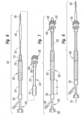
- FIG 6 is an exploded view, and Figures 7 and 8 are assembled views, of an exemplary system 50 for delivering the prosthetic heart valve of the present invention. Modified components of the delivery system 50 are also shown in Figures 9 and 10 .
- the delivery system 50 includes a balloon catheter 52 having the balloon 40 on its distal end and an obturator 54 on a proximal end.
- the obturator 54 presents a proximal coupling 56 that receives a luer connector or other such fastener of a Y-fitting 58.
- the aforementioned nose cone 38 may attach to the distalmost end of the catheter 52, but more preferably attaches to a wire (not shown) inserted through the center lumen of the balloon catheter 52.
- the catheter 52 and the nose cone 38 pass through a hollow handle 60 having a proximal section 62 and a distal section 64.
- a distal end of the distal handle section 64 firmly attaches to a hub 66 of a valve holder 68, which in turn attaches to the prosthetic heart valve component 30. Details of the valve holder 68 will be given below with reference to Figures 11A-11E .
- the two sections 62, 64 of the handle 60 are desirably formed of a rigid material, such as a molded plastic, and coupled to one another to form a relatively rigid and elongated tube for manipulating the prosthetic valve component 30 attached to its distal end.
- the distal section 64 may be easily coupled to the holder hub 66 and therefore provide a convenient tool for managing the valve component 30 during pre-surgical rinsing steps.
- the distal section 64 features a distal tubular segment 70 that couples to the holder hub 66, and an enlarged proximal segment 72 having an opening on its proximal end that receives a tubular extension 74 of the proximal handle section 62.
- Figure 6 shows an O-ring 76 that may be provided on the exterior of the tubular extension 74 for a frictional interference fit to prevent the two sections from disengaging.
- the distal tubular segment 70 may also have an O-ring for firmly coupling to the holder hub 66, or may be attached with threading or the like.
- the balloon 40 on the catheter 52 is packaged within the proximal handle section 62 for protection and ease of handling. Coupling the proximal and distal handle sections 62, 64 therefore "loads" the system 50 such that the balloon catheter 52 may be advanced through the continuous lumen leading to the valve component 30.
- Figures 9 and 10 illustrate a delivery system 50 similar to that shown in Figure 7 , but with alternative couplers 77 on both the proximal and distal handle sections 62, 64 in the form of cantilevered teeth that snap into complementary recesses formed in the respective receiving apertures. Likewise, threading on the mating parts could also be used, as well as other similar expedients.
- Figure 9 shows the balloon 40 inflated to expand the valve component coupling stent 36.
- the prosthetic valve component 30 incorporates bioprosthetic tissue leaflets and is packaged and stored attached to the holder 68 but separate from the other introduction system 50 components.
- bioprosthetic tissue is packaged and stored in a jar with preservative solution for long shelf life, while the other components are packaged and stored dry.
- an elongated lumen (not numbered) extends from the proximal end of the Y-fitting 58 to the interior of the balloon 40.
- the Y-fitting 58 desirably includes an internally threaded connector 80 for attachment to an insufflation system, or a side port 82 having a luer fitting 84 or similar expedient may be used for insufflation of the balloon 40.
- Figures 7 and 8 show two longitudinal positions of the catheter 52 and associated structures relative to the handle 60 and its associated structures.
- the balloon 40 primarily resides within the distal handle section 64.
- Figure 7 illustrates the delivery configuration of the introduction system 50, in which the surgeon advances the prosthetic valve component 30 from outside the body into a location adjacent the target annulus.
- the nose cone 38 extends around and protects a distal end of the conical undeployed coupling stent 36. This configuration is also seen in Figure 5D , albeit with the holder 68 removed for clarity. Note the spacing S between the proximal coupling 56 and the proximal end of the handle 60.
- the surgeon advances the prosthetic valve component 30 into its desired implantation position at the valve annulus, and then advances the balloon 40 through the valve component and inflates it.
- the operator converts the delivery system 50 from the retracted configuration of Figure 7 to the deployment configuration of Figure 8 , with the balloon catheter 40 displaced distally as indicated by the arrow 78 to disengage the nose cone 38 from the coupling stent 36.
- the proximal coupling 56 now contacts the proximal end of the handle 60, eliminating the space S indicated in Figure 7 .
- the prosthetic valve component 30 may be implanted at the valve annulus with a pre-deployed base stent 24, as explained above, or without.
- the coupling stent 36 may be robust enough to anchor the valve component 30 directly against the native annulus (with or without leaflet excision) in the absence of the base stent 24. Consequently, the description of the system 50 for introducing the prosthetic heart valve should be understood in the context of operating with or without the pre-deployed base stent 24.
- valve component 30 Prior to a further description of operation of the delivery system 50, a more detailed explanation of the valve component 30 and valve holder 68 is necessary.
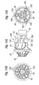
- Figures 11A-11E show a number of perspective and other views of the exemplary valve component 30 mounted on the delivery holder 68 used in the present invention.
- the valve component 30 comprises the prosthetic valve 34 having the coupling stent 36 attached to an inflow end thereof.
- the prosthetic valve 34 comprises a commercially available off-the-shelf non-expandable, non-collapsible commercial prosthetic valve. Any number of prosthetic heart valves can be retrofit to attach the coupling stent 36, and thus be suitable for use in the context of the present invention.
- the prosthetic valve 34 may be a mechanical valve or a valve with flexible leaflets, either synthetic or bioprosthetic. In a preferred embodiment, however, the prosthetic valve 34 includes bioprosthetic tissue leaflets 86 ( Figure 11A ). Furthermore, as mentioned above, the prosthetic valve 34 is desirably a Carpentier-Edwards PERIMOUNT Magna ® Aortic Heart Valve (e.g., model 3000TFX) available from Edwards Lifesciences of Irvine, California.
- Carpentier-Edwards PERIMOUNT Magna ® Aortic Heart Valve e.g., model 3000TFX
- the coupling stent 36 preferably attaches to the ventricular (or inflow) aspect of the valve's sewing ring 42 during the manufacturing process in a way that preserves the integrity of the sewing ring and prevents reduction of the valve's effective orifice area (EOA).
- EOA effective orifice area
- the coupling stent 36 will be continuously sutured to sewing ring 42 in a manner that maintains the outer contours of the sewing ring.
- Sutures may be passed through apertures or eyelets in the stent skeleton, or through a cloth covering that in turn is sewn to the skeleton.
- Other connection solutions include prongs or hooks extending inward from the stent, ties, Velcro, snaps, adhesives, etc.
- the coupling stent 36 may be more rigidly connected to rigid components within the prosthetic valve 34.
- the surgeon can seat the sewing ring 42 against the annulus in accordance with a conventional surgery. This gives the surgeon familiar tactile feedback to ensure that the proper patient-prosthesis match has been achieved.
- placement of the sewing ring 42 against the outflow side of the annulus helps reduce the probability of migration of the valve component 30 toward the ventricle.
- the coupling stent 36 may be a pre-crimped, tapered, 316L stainless steel balloon-expandable stent, desirably covered by a polyester skirt 88 to help seal against paravalvular leakage and promote tissue ingrowth once implanted within the base stent 24 (see Figure 5F ).
- the coupling stent 36 transitions between the tapered constricted shape of Figures 11A-11E to its flared expanded shape shown in Figure 5F , and also in Figure 10 .
- the coupling stent 36 desirably comprises a plurality of sawtooth-shaped or otherwise angled, serpentine or web-like struts 90 connected to three generally axially-extending posts 92.
- the posts 92 desirably feature a series of evenly spaced apertures to which sutures holding the polyester skirt 88 in place may be anchored.
- the stent 36 when expanded flares outward and conforms closely against the inner surface of the base stent 24, and has an axial length substantially the same as the base stent.
- Anchoring devices such as barbs or other protruberances from the coupling stent 36 may be provided to enhance the frictional hold between the coupling stent and the base stent 24.
- both the base stent 24 and the coupling stent 36 are desirably plastically-expandable to provide a firmer anchor for the valve 34; first to the annulus with or without native leaflets, and then between the two stents.
- the stents may be expanded using a balloon or mechanical expander as described below.
- the holder 68 comprises the aforementioned proximal hub 66 and a thinner distal extension 94 thereof forming a central portion of the holder.
- Three legs 96a, 96b, 96c circumferentially equidistantly spaced around the central extension 94 and projecting radially outward therefrom comprise inner struts 98 and outer commissure rests 100.
- the prosthetic valve 34 preferably includes a plurality, typically three, commissures 102 that project in an outflow direction.
- the commissure rests 100 preferably incorporate depressions into which fit the tips of the commissures 102.
- the holder 68 is formed of a rigid polymer such as Delrin or polypropylene that is transparent to increase visibility of an implant procedure. As best seen in Figure 11E , the holder 68 exhibits openings between the legs 96a, 96b, 96c to provide a surgeon good visibility of the valve leaflets 86, and the transparency of the legs further facilitates visibility and permits transmission of light therethrough to minimize shadows.
- Figure 11E also illustrate a series of through holes in the legs 96a, 96b, 96c permitting connecting sutures to be passed through fabric in the prosthetic valve 34 and across a cutting guide in each leg. As is known in the art, severing a middle length of suture that is connected to the holder 68 and passes through the valve permits the holder to be pulled free from the valve when desired.
- FIGS 11C and 11D illustrate a somewhat modified coupling stent 36 from that shown in Figures 11A and 11B , wherein the struts 90 and axially-extending posts 92 are better defined.
- the posts 92 are somewhat wider and more robust than the struts 90, as the latter provide the stent 36 with the ability to expand from the conical shape shown to a more tubular configuration.
- a generally circular reinforcing ring 104 abuts the valve sewing ring 42.
- Both the posts 92 and the ring 104 further include a series of through holes 106 that may be used to secure the polyester skirt 88 to the stent 36 using sutures or the like.
- a number of variants of the coupling stent 36 are also described below.
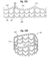
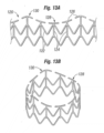
- Figures 12A-12B illustrate the exemplary coupling stent 36 in both a flat configuration (12A) and a tubular configuration (12B) that is generally the expanded shape.
- the web-like struts 90 and a reinforcing ring 104 connect three generally axially-extending posts 92.
- a plurality of evenly spaced apertures 106 provide anchors for holding the polyester skirt 88 (see Figure 11B ) in place.
- the web-like struts 90 also include a series of axially-extending struts 108.
- an upper end of the coupling stent 36 that connects to the sewing ring of the valve and is defined by the reinforcing ring 104 follows an undulating path with alternating arcuate troughs 110 and peaks 112.
- the exemplary prosthetic valve 34 has an undulating sewing ring 42 to which the upper end of the coupling stent 36 conforms.
- the geometry of the stent 36 matches that of the undulating sewing ring 42.
- the tubular version of Figure 12B is an illustration of an expanded configuration, although the balloon 40 may over-expand the free (lower) end of the stent 36 such that it ends up being slightly conical.
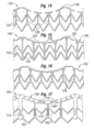
- Figures 13A and 13B show an alternative coupling stent 120, again in flattened and tubular configurations, respectively.
- the coupling stent 120 includes web-like struts 122 extending between a series of axially-extending struts 124.
- all of the axially-extending struts 124 are substantially the same thin cross-sectional size.
- the upper or connected end of the stent 120 again includes a reinforcing ring 126, although this version is interrupted with a series of short lengths separated by gaps.
- the upper end defines a plurality of alternating troughs 128 and peaks 130, with lengths of the reinforcing ring 126 defining the peaks.
- the axially-extending struts 124 are in-phase with the scalloped shape of the upper end of the stent 120, and coincide with the peaks and the middle of the troughs.
- the gaps between the lengths making up the reinforcing ring 126 permit the stent 120 to be matched with a number of different sized prosthetic valves 34. That is, the majority of the stent 120 is expandable having a variable diameter, and providing gaps in the reinforcing ring 126 allows the upper end to also have a variable diameter so that it can be shaped to match the size of the corresponding sewing ring. This reduces manufacturing costs as correspondingly sized stents need not be used for each different sized valve.
- Figure 14 is a plan view of a still further alternative coupling stent 132 that is very similar to the coupling stent 120, including web-like struts 134 connected between a series of axially-extending struts 136, and the upper end is defined by a reinforcing ring 138 formed by a series of short lengths of struts.
- the peaks of the undulating upper end have gaps as opposed to struts.
- the axially-extending struts 136 are out-of-phase with the scalloped shape of the upper end of the stent 132, and do not correspond to the peaks and the middle of the troughs.
- Figure 15 illustrates an exemplary coupling stent 140 again having the expandable struts 142 between the axially-extending struts 144, and an upper reinforcing ring 146.
- the axially-extending struts 144 are in-phase with peaks and troughs of the upper end of the stent.
- the reinforcing ring 146 is a cross between the earlier-described such rings as it is continuous around its periphery but also has a variable diameter. That is, the ring 146 comprises a series of lengths of struts 148 of fixed length connected by thinner bridge portions 150 of variable length.
- the bridge portions 150 are each formed with a radius so that they can be either straightened (lengthened) or bent more (compressed).
- a series of apertures 152 are also formed in an upper end of the stent 142 provide anchor points for sutures or other attachment means when securing the stent to the sewing ring of the corresponding prosthetic valve.
- an alternative coupling stent 154 is identical to the stent 140 of Figure 15 , although the axially-extending struts 156 are out-of-phase with the peaks and troughs of the undulating upper end.
- Figure 17 shows a still further variation on a coupling stent 160, which has a series of expandable struts 162 connecting axially-extending struts 164.
- the web-like struts 162 also include a series of axially-extending struts 166, although these are thinner than the main axial struts 164.
- a reinforcing ring 168 is also thicker than the web-like struts 162, and features one or more gaps 170 in each trough such that the ring is discontinuous and expandable.
- Barbs 172, 174 on the axially extending struts 164, 166 may be utilized to enhance retention between the coupling stent 160 and a base stent with which it cooperates, or with annular tissue in situations where there is no base stent, as explained above.
- the two-component valve systems described herein utilize an outer or base stent (such as base stent 24) and a valve component having an inner or valve stent (such as coupling stent 36).
- the valve and its stent advance into the lumen of the pre-anchored outer stent and the valve stent expands to join the two stents and anchor the valve into its implant position.
- a number of variations of coupling stent that attach to the valve component have been shown and described above.
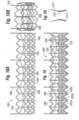
- Figures 18-20 illustrate exemplary base stents and cooperation between the two stents.
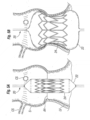
- Figures 18A and 18B show an exemplary embodiment of a base stent 180 comprising a plurality of radially-expandable struts 182 extending between a plurality of generally axially-extending struts 184.
- the struts 182 form chevron patterns between the struts 184, although other configurations such as serpentine or diamond-shaped could also be used.
- the top and bottom rows of the radially-expandable struts 182 are arranged in apposition so as to form a plurality of triangular peaks 186 and troughs 188.
- the axial struts 184 are in-phase with the troughs 188.
- the flattened view of Figure 18A shows four axial projections 190 that each extend upward from one of the axial struts 184.
- the exemplary base stent 180 desirably has three evenly circumferentially spaced projections, as seen around the periphery in the tubular version of Figure 18B , providing location markers for the base stent. These markers thus make it easier for the surgeon to orient the stent 180 such that the markers align with the native commissures.
- the visible projections 190 provide reference marks such that the inner stent can be properly oriented within the base stent.
- the projections 190 may be differently colored than the rest of the stent 180, or have radiopaque indicators thereon.
- the length of the projections 190 above the upper row of middle struts 182 may also be calibrated to help the surgeon axially position the stent 180. For example, the distance from the tips of the projections 190 to the level of the native annulus could be determined, and the projections 190 located at a particular anatomical landmark such as just below the level of the coronary ostia.
- An undulating dashed line 192 in Figure 18A represents the upper end of the inner or coupling stent 140, which is shown in phantom superimposed over the base stent 180.
- the dashed line 192 also represents an undulating sewing ring, and it bears repeating that the sewing ring could be planar such that the upper end of the coupling stent is also planar.
- the coupling stent 140 includes axially-extending struts that are in-phase with the respective peaks and troughs of the scalloped upper end of the stent.
- the peaks of the scalloped upper end of the coupling stent correspond rotationally (are in-phase) with the axial struts 184 that have the projections 190. Therefore, because the coupling stent 140 axial struts are in-phase with the peaks of the upper end thereof, they are also in-phase with the axial struts 184 of the base stent 180. Conversely, a coupling stent may have axial struts out-of-phase with peaks of the upper end thereof, in which case the respective axial struts of the two stents are also out-of-phase.
- Figure 19 shows an alternative base stent 200 that generally has the same components as the base stent 180 of Figure 18A , but the axial struts 184 extend between the peaks 186 of the outer rows of middle struts 182. In the earlier embodiment, the axial struts 184 extended between the troughs 188.
- the coupling stent 154 of Figure 16 is shown in phantom superimposed over the base stent 200 to illustrate how the axial struts of the two stents are now out-of-phase to increase interlocking therebetween.
- the stent 200 also exhibits different rows of middle struts 182. Specifically, a first row 202a defines V's having relatively shallow angles, a second row 202b defines V's with medium angles, and a third row 202c defined V's with more acute angles.
- the different angles formed by the middle struts 182 in these rows helps shape the stent into a conical form when expanded.
- the struts in the third row 202c which is farthest from the prosthetic valve have the greatest capacity for expansion to accommodate the transition from the collapsed conical shape of the stent to the expanded tubular shape.
- the peaks and troughs of the web-like expandable struts on the two stents could be oriented out-of-phase or in-phase.
- the peaks and troughs of the two stents are out of phase so that expansion of the inner stent causes its peaks to deform outwardly into the troughs of the outer stent, and thereby provide interlocking structure therebetween.
- the variations described above provide a number of permutations of this cooperation.
- axial projections on one or both of stents could be bent to provide an interference with the other stent.
- the lower ends of the axial struts 108 in the stent 36 shown in Figure 12A could be bent outward by expansion of a non-uniform shaped balloon such that they extend in voids within the outer stent.
- the embodiment of Figure 17 illustrates barbs 172, 174 that can be bent outward into interference with the corresponding base stent.
- Strut ends or barbs that transition from one position to another to increase retention between the two stents can be actuated by mechanical bending, such as with a balloon, or through an automatic shape change upon installation within the body.
- some shape memory alloys such as Nitinol can be designed to undergo a shape change upon a temperature change, such that they assume a first shape at room temperature, and a second shape at body temperature.
- Figure 20 illustrates a simplified means for increasing retention between the two stents.
- An inner valve stent 210 fits within an outer base stent 212 such that a lower end 214 thereof extends below the outer stent.
- the lower end 214 is caused to bend or wrap outward to prevent relative upward movement of the inner stent within the outer stent.
- Figure 21 is a perspective view of a device 220 for delivering and expanding a base stent 222 with a mechanical expander 224.
- the expander 224 includes a plurality of spreadable fingers 226 over which the base stent 22 is crimped.
- the device 220 includes a syringe-like apparatus including a barrel 230 within which a plunger 232 linearly slides.
- the fingers 226 are axially fixed but capable of pivoting or flexing with respect to the barrel 230.
- the distal end of the plunger 232 has an outer diameter that is greater than the diameter circumscribed by the inner surfaces of the spreadable fingers 226.
- proximal lead-in ramp on the inside of the fingers 226 such that distal movement of the plunger 232 with respect to the barrel 230 gradually cams the fingers outward.
- the two positions of the plunger 232 are shown in Figures 21 and 23 .
- the plunger 232 may also be threadingly received within the barrel 230.
- the plunger 232 may be formed in two parts freely rotatable with respect to one another, with a proximal part threadingly received within the barrel 230 while a distal part does not rotate with respect to the barrel and merely cams the fingers 226 outward.
- a mechanical linkage may be used instead of a camming action whereby levers hinged together create outward movement of the fingers 226.
- a hybrid version using an inflatable balloon with mechanical parts mounted on the outside of the balloon may be utilized.
- the fingers 226 have a contoured exterior profile such that they expand the base stent 222 into a particular shape that better fits the heart valve annulus.
- the base stent 222 may be expanded into an hourglass shape with wider upper and lower ends and a smaller midsection, and/or an upper end may be formed with a tri-lobular shape to better fit the aortic sinuses.
- the tri-lobular shape is useful for orienting the base stent 222 upon implant, and also for orienting the coupling stent of the valve component that is received therewithin.
- the two-component valve system illustrated in the preceding figures provides a device and method that substantially reduces the time of the surgical procedure as compared with replacement valves that are sutured to the tissue after removing the native leaflets.
- the stent 24 of Figures 5-9 may be deployed quickly and the valve component 30 may also be quickly attached to the stent. This reduces the time required on extracorporeal circulation and thereby substantially reduces the risk to the patient.
- the present invention having the pre-anchored stent, within which the valve and its stent mount, permits the annulus to be expanded to accommodate a larger valve than otherwise would be possible.
- LVOT left ventricular outflow tract
- significantly expanding the LVOT means expanding it by at least 10%, more preferably between about 10-30%.
- the LVOT may be expanded 1.5-5 mm depending on the nominal orifice size. This expansion of the annulus creates an opportunity to increase the size of a surgically implanted prosthetic valve.
- the present invention employs a balloon-expandable base stent, and a balloon-expandable valve stent.
- the combination of these two stents permits expansion of the LVOT at and just below the aortic annulus, at the inflow end of the prosthetic valve.
- the interference fit created between the outside of the base stent and the LVOT secures the valve without pledgets or sutures taking up space, thereby allowing for placement of the maximum possible valve size.
- a larger valve size than would otherwise be available with conventional surgery enhances volumetric blood flow and reduces the pressure gradient through the valve.
- embodiments of the present invention provide important new devices and methods wherein a valve may be securely anchored to a body lumen in a quick and efficient manner.
- Embodiments of the present invention provide a means for implanting a prosthetic valve in a surgical procedure without requiring the surgeon to suture the valve to the tissue. Accordingly, the surgical procedure time is substantially decreased.
- the stent may be used to maintain the native valve in a dilated condition. As a result, it is not necessary for the surgeon to remove the native leaflets, thereby further reducing the procedure time.
- the present invention provides an improved system wherein a valve member may be replaced in a more quick and efficient manner. More particularly, it is not necessary to cut any sutures in order to remove the valve. Rather, the valve member may be disconnected from the stent (or other base stent) and a new valve member may be connected in its place. This is an important advantage when using biological tissue valves or other valves having limited design lives.
Landscapes
- Health & Medical Sciences (AREA)
- Cardiology (AREA)
- Engineering & Computer Science (AREA)
- Biomedical Technology (AREA)
- Vascular Medicine (AREA)
- Transplantation (AREA)
- Oral & Maxillofacial Surgery (AREA)
- Heart & Thoracic Surgery (AREA)
- Life Sciences & Earth Sciences (AREA)
- Animal Behavior & Ethology (AREA)
- General Health & Medical Sciences (AREA)
- Public Health (AREA)
- Veterinary Medicine (AREA)
- Mechanical Engineering (AREA)
- Prostheses (AREA)
- Media Introduction/Drainage Providing Device (AREA)
Claims (15)
- System zur Zuführung einer Herzklappenprothese, umfassend:eine Klappenkomponente (30), die aufweist:eine Klappenprothese (34), die ein Einströmende und ein Ausströmende aufweist, und eine nicht expandierbare, nicht komprimierbare Öffnung an dem Einströmende der Klappenprothese (34); undeinen expandierbaren Kopplungsstent (36), der sich von dem Einströmende der Klappenprothese (34) in einer distalen Richtung weg von dem Ausströmende der Klappenprothese erstreckt, wobei der Kopplungsstent (36) einen kontrahierten Zustand zur Zuführung zu einem Implantationsort und einen expandierten Zustand aufweist;einen Klappenhalter (68), der mit dem Ausströmende der Klappenprothese (34) verbunden ist;einen Ballonkatheter (20), der einen Ballon (22) aufweist; undeinen Griff (60), der dazu ausgebildet ist, an einem proximalen Ende des Klappenhalters (68) angebracht zu werden, und ein Lumen zum Durchtritt des Katheters (20) aufweist, wobei sich der Ballon (22) distal durch den Griff (60), an dem Halter (68) vorbei und durch die Klappenkomponente (30) erstreckt.
- System nach Anspruch 1, wobei die Klappenprothese (34) eine handelsübliche Klappe aufweist, die einen Nähring (42) aufweist, wobei der Kopplungsstent (36) an dem Nähring (42) befestigt ist.
- System nach Anspruch 1, wobei der kontrahierte Zustand des Kopplungsstents (36) konisch, sich in einer distalen Richtung verjüngend, ausgebildet ist.
- System nach Anspruch 1, wobei der kontrahierte Zustand des Kopplungsstents (36) konisch ist und sich in distaler Richtung verjüngt, wobei der Ballonkatheter (20) ferner einen im Allgemeinen konischen Nasenkonus (38) an seinem distalen Ende aufweist, der sich durch die Klappenkomponente (30) erstreckt und mit einem distalen Ende des Kopplungsstents (36) in seinem kontrahierten Zustand in Eingriff ist.
- System nach Anspruch 1, wobei der Griff (60) eine proximale Griffsektion (62) und eine distale Griffsektion (64) umfasst, die in Reihe miteinander gekoppelt werden können, um ein durchgehendes Lumen zu bilden, und wobei die distale Griffsektion (64) dazu ausgebildet ist, an einem proximalen Zentrum (66) des Halters (68) anzukoppeln, um eine manuelle Beeinflussung der Klappenkomponente (30) unter Verwendung der distalen Griffsektion (64) vor der Verbindung mit der proximalen Griffsektion (62) zu ermöglichen.
- System nach Anspruch 5, wobei der Ballonkatheter (20) und die proximale Griffsektion (62) zusammen mit dem Ballon (20, 40) innerhalb des Lumens der proximalen Sektion verpackt sind.
- System nach Anspruch 1, wobei die Klappenkomponente (30), die auf dem Halter (68) montiert ist, separat von dem Griff (60) und dem Ballonkatheter (20) verpackt ist.
- System nach Anspruch 3 oder 4, wobei der Kopplungsstent (36) eine Vielzahl von radial expandierbaren Streben umfasst, von denen wenigstens einige in Reihen angeordnet sind, und wobei die am weitesten distal gelegene Reihe die größte Expansionsfähigkeit vom kontrahierten Zustand zum expandierten Zustand aufweist.
- System nach Anspruch 1, wobei der Kopplungsstent (36) eine Vielzahl radial expandierbarer Streben umfasst, und eine Reihe, die am weitesten von der prothetischen Klappe (34) entfernt ist, alternierende Spitzen und Täler aufweist.
- System nach Anspruch 1, wobei der kontrahierte Zustand des Kopplungsstents (36) konisch ist, und wobei der Ballon (22) auf dem Ballonkatheter (20) ein distales expandiertes Ende größer als sein proximales expandiertes Ende aufweist, um auf den Kopplungsstent (36) eine größere Expansionsverformung auszuüben als auf die Klappenprothese (34).
- System nach Anspruch 1, weiter enthaltend einen mechanischen Expandierer und einen Basisstent, der über einem mechanischen Expandierer montiert ist, wobei der mechanische Expandierer dazu ausgebildet ist, den Basisstent an dem Herzklappenanulus auszubringen, und der Basisstent dazu ausgebildet ist, sich an einem Herzklappenanulus zu verankern und darin eine Öffnung zu definieren.
- System nach Anspruch 11, wobei der Basisstent expandierbar ist und einen kontrahierten Zustand zur Zuführung zu einem Implantationsort in der Nähe eines Herzklappenanulus und einen expandierten Zustand aufweist, der so bemessen ist, dass er den Herzklappenanulus berührt und sich dort verankert.
- System nach Anspruch 12, wobei der Basisstent plastisch expandierbar ist.
- System nach Anspruch 1, wobei der Kopplungsstent (36) plastisch expandierbar ist.
- System nach Anspruch 1, wobei der Halter ein proximales Zentrum (66) und ein hindurchführendes Lumen aufweist.
Priority Applications (1)
| Application Number | Priority Date | Filing Date | Title |
|---|---|---|---|
| EP23193742.6A EP4331539A3 (de) | 2008-12-19 | 2009-12-18 | Schnellverbindungsherzklappenprothese und verfahren |
Applications Claiming Priority (5)
| Application Number | Priority Date | Filing Date | Title |
|---|---|---|---|
| US13939808P | 2008-12-19 | 2008-12-19 | |
| US12/635,471 US8308798B2 (en) | 2008-12-19 | 2009-12-10 | Quick-connect prosthetic heart valve and methods |
| PCT/US2009/068693 WO2010080594A2 (en) | 2008-12-19 | 2009-12-18 | Quick-connect prosthetic heart valve and methods |
| EP17190960.9A EP3290004B1 (de) | 2008-12-19 | 2009-12-18 | Herzklappenprothese mit schnellkupplung |
| EP09837975.3A EP2379009B1 (de) | 2008-12-19 | 2009-12-18 | Herzklappenprothese mit schnellkupplung |
Related Parent Applications (3)
| Application Number | Title | Priority Date | Filing Date |
|---|---|---|---|
| EP17190960.9A Division-Into EP3290004B1 (de) | 2008-12-19 | 2009-12-18 | Herzklappenprothese mit schnellkupplung |
| EP17190960.9A Division EP3290004B1 (de) | 2008-12-19 | 2009-12-18 | Herzklappenprothese mit schnellkupplung |
| EP09837975.3A Division EP2379009B1 (de) | 2008-12-19 | 2009-12-18 | Herzklappenprothese mit schnellkupplung |
Related Child Applications (1)
| Application Number | Title | Priority Date | Filing Date |
|---|---|---|---|
| EP23193742.6A Division EP4331539A3 (de) | 2008-12-19 | 2009-12-18 | Schnellverbindungsherzklappenprothese und verfahren |
Publications (2)
| Publication Number | Publication Date |
|---|---|
| EP3842012A1 EP3842012A1 (de) | 2021-06-30 |
| EP3842012B1 true EP3842012B1 (de) | 2023-08-30 |
Family
ID=42267224
Family Applications (4)
| Application Number | Title | Priority Date | Filing Date |
|---|---|---|---|
| EP23193742.6A Pending EP4331539A3 (de) | 2008-12-19 | 2009-12-18 | Schnellverbindungsherzklappenprothese und verfahren |
| EP09837975.3A Not-in-force EP2379009B1 (de) | 2008-12-19 | 2009-12-18 | Herzklappenprothese mit schnellkupplung |
| EP21152811.2A Active EP3842012B1 (de) | 2008-12-19 | 2009-12-18 | Herzklappenprothese mit schnellkupplung |
| EP17190960.9A Active EP3290004B1 (de) | 2008-12-19 | 2009-12-18 | Herzklappenprothese mit schnellkupplung |
Family Applications Before (2)
| Application Number | Title | Priority Date | Filing Date |
|---|---|---|---|
| EP23193742.6A Pending EP4331539A3 (de) | 2008-12-19 | 2009-12-18 | Schnellverbindungsherzklappenprothese und verfahren |
| EP09837975.3A Not-in-force EP2379009B1 (de) | 2008-12-19 | 2009-12-18 | Herzklappenprothese mit schnellkupplung |
Family Applications After (1)
| Application Number | Title | Priority Date | Filing Date |
|---|---|---|---|
| EP17190960.9A Active EP3290004B1 (de) | 2008-12-19 | 2009-12-18 | Herzklappenprothese mit schnellkupplung |
Country Status (9)
| Country | Link |
|---|---|
| US (7) | US8308798B2 (de) |
| EP (4) | EP4331539A3 (de) |
| JP (2) | JP5498508B2 (de) |
| CN (2) | CN104068947B (de) |
| AU (2) | AU2009335700B2 (de) |
| BR (1) | BRPI0923190A2 (de) |
| CA (2) | CA2966311C (de) |
| ES (1) | ES2880016T3 (de) |
| WO (1) | WO2010080594A2 (de) |
Families Citing this family (451)
| Publication number | Priority date | Publication date | Assignee | Title |
|---|---|---|---|---|
| IL154433A0 (en) | 2000-08-18 | 2003-09-17 | Atritech Inc | Expandable implant devices for filtering blood flow from atrial appendages |
| WO2004030568A2 (en) * | 2002-10-01 | 2004-04-15 | Ample Medical, Inc. | Device and method for repairing a native heart valve leaflet |
| US8308797B2 (en) | 2002-01-04 | 2012-11-13 | Colibri Heart Valve, LLC | Percutaneously implantable replacement heart valve device and method of making same |
| US9579194B2 (en) * | 2003-10-06 | 2017-02-28 | Medtronic ATS Medical, Inc. | Anchoring structure with concave landing zone |
| US8840663B2 (en) | 2003-12-23 | 2014-09-23 | Sadra Medical, Inc. | Repositionable heart valve method |
| US20120041550A1 (en) | 2003-12-23 | 2012-02-16 | Sadra Medical, Inc. | Methods and Apparatus for Endovascular Heart Valve Replacement Comprising Tissue Grasping Elements |
| US8579962B2 (en) | 2003-12-23 | 2013-11-12 | Sadra Medical, Inc. | Methods and apparatus for performing valvuloplasty |
| US8828078B2 (en) | 2003-12-23 | 2014-09-09 | Sadra Medical, Inc. | Methods and apparatus for endovascular heart valve replacement comprising tissue grasping elements |
| US7959666B2 (en) | 2003-12-23 | 2011-06-14 | Sadra Medical, Inc. | Methods and apparatus for endovascularly replacing a heart valve |
| US8603160B2 (en) | 2003-12-23 | 2013-12-10 | Sadra Medical, Inc. | Method of using a retrievable heart valve anchor with a sheath |
| US11278398B2 (en) | 2003-12-23 | 2022-03-22 | Boston Scientific Scimed, Inc. | Methods and apparatus for endovascular heart valve replacement comprising tissue grasping elements |
| US20050137687A1 (en) | 2003-12-23 | 2005-06-23 | Sadra Medical | Heart valve anchor and method |
| US8343213B2 (en) | 2003-12-23 | 2013-01-01 | Sadra Medical, Inc. | Leaflet engagement elements and methods for use thereof |
| US7381219B2 (en) | 2003-12-23 | 2008-06-03 | Sadra Medical, Inc. | Low profile heart valve and delivery system |
| US9526609B2 (en) | 2003-12-23 | 2016-12-27 | Boston Scientific Scimed, Inc. | Methods and apparatus for endovascularly replacing a patient's heart valve |
| US7780725B2 (en) | 2004-06-16 | 2010-08-24 | Sadra Medical, Inc. | Everting heart valve |
| DE102005003632A1 (de) | 2005-01-20 | 2006-08-17 | Fraunhofer-Gesellschaft zur Förderung der angewandten Forschung e.V. | Katheter für die transvaskuläre Implantation von Herzklappenprothesen |
| JP4912395B2 (ja) | 2005-05-24 | 2012-04-11 | エドワーズ ライフサイエンシーズ コーポレイション | 迅速配置式補綴用心臓弁 |
| US7780723B2 (en) | 2005-06-13 | 2010-08-24 | Edwards Lifesciences Corporation | Heart valve delivery system |
| US20070213813A1 (en) | 2005-12-22 | 2007-09-13 | Symetis Sa | Stent-valves for valve replacement and associated methods and systems for surgery |
| CN101415379B (zh) | 2006-02-14 | 2012-06-20 | 萨德拉医学公司 | 用于输送医疗植入物的系统 |
| US9867530B2 (en) | 2006-08-14 | 2018-01-16 | Volcano Corporation | Telescopic side port catheter device with imaging system and method for accessing side branch occlusions |
| US9883943B2 (en) | 2006-12-05 | 2018-02-06 | Valtech Cardio, Ltd. | Implantation of repair devices in the heart |
| US7896915B2 (en) | 2007-04-13 | 2011-03-01 | Jenavalve Technology, Inc. | Medical device for treating a heart valve insufficiency |
| WO2009009799A1 (en) | 2007-07-12 | 2009-01-15 | Volcano Corporation | Catheter for in vivo imaging |
| US10219780B2 (en) | 2007-07-12 | 2019-03-05 | Volcano Corporation | OCT-IVUS catheter for concurrent luminal imaging |
| US9596993B2 (en) | 2007-07-12 | 2017-03-21 | Volcano Corporation | Automatic calibration systems and methods of use |
| US8425593B2 (en) | 2007-09-26 | 2013-04-23 | St. Jude Medical, Inc. | Collapsible prosthetic heart valves |
| US9532868B2 (en) | 2007-09-28 | 2017-01-03 | St. Jude Medical, Inc. | Collapsible-expandable prosthetic heart valves with structures for clamping native tissue |
| EP2254512B1 (de) * | 2008-01-24 | 2016-01-06 | Medtronic, Inc. | Marker für herzklappenprothesen |
| US9044318B2 (en) | 2008-02-26 | 2015-06-02 | Jenavalve Technology Gmbh | Stent for the positioning and anchoring of a valvular prosthesis |
| WO2011104269A1 (en) | 2008-02-26 | 2011-09-01 | Jenavalve Technology Inc. | Stent for the positioning and anchoring of a valvular prosthesis in an implantation site in the heart of a patient |
| US9061119B2 (en) * | 2008-05-09 | 2015-06-23 | Edwards Lifesciences Corporation | Low profile delivery system for transcatheter heart valve |
| EP2296744B1 (de) | 2008-06-16 | 2019-07-31 | Valtech Cardio, Ltd. | Annuloplastievorrichtungen |
| DE202009018984U1 (de) | 2008-07-15 | 2015-01-29 | St. Jude Medical, Inc. | Tasche zur Verwendung in einer Herzklappenprothese |
| US8652202B2 (en) | 2008-08-22 | 2014-02-18 | Edwards Lifesciences Corporation | Prosthetic heart valve and delivery apparatus |
| AU2009295960A1 (en) | 2008-09-29 | 2010-04-01 | Cardiaq Valve Technologies, Inc. | Heart valve |
| EP2341871B1 (de) | 2008-10-01 | 2017-03-22 | Edwards Lifesciences CardiAQ LLC | Abgabesystem für ein gefässimplantat |
| EP2617388B2 (de) | 2008-10-10 | 2019-11-06 | Boston Scientific Scimed, Inc. | Medizinische Vorrichtungen und Abgabesysteme zur Abgabe von medizinischen Vorrichtungen |
| US8137398B2 (en) * | 2008-10-13 | 2012-03-20 | Medtronic Ventor Technologies Ltd | Prosthetic valve having tapered tip when compressed for delivery |
| US8470013B2 (en) * | 2008-10-20 | 2013-06-25 | Imds Corporation | Systems and methods for aneurysm treatment and vessel occlusion |
| WO2010065265A2 (en) | 2008-11-25 | 2010-06-10 | Edwards Lifesciences Corporation | Apparatus and method for in situ expansion of prosthetic device |
| US8308798B2 (en) * | 2008-12-19 | 2012-11-13 | Edwards Lifesciences Corporation | Quick-connect prosthetic heart valve and methods |
| US10517719B2 (en) | 2008-12-22 | 2019-12-31 | Valtech Cardio, Ltd. | Implantation of repair devices in the heart |
| AU2010218384B2 (en) | 2009-02-27 | 2014-11-20 | St. Jude Medical, Inc. | Stent features for collapsible prosthetic heart valves |
| EP3708123A1 (de) * | 2009-03-30 | 2020-09-16 | JC Medical, Inc. | Nahtlose herzklappenprothesen sowie vorrichtungen und verfahren zur einführung |
| EP4119098A1 (de) | 2009-04-15 | 2023-01-18 | Edwards Lifesciences CardiAQ LLC | Gefässimplantat und freisetzungssystem |
| US8348998B2 (en) | 2009-06-26 | 2013-01-08 | Edwards Lifesciences Corporation | Unitary quick connect prosthetic heart valve and deployment system and methods |
| US9180007B2 (en) | 2009-10-29 | 2015-11-10 | Valtech Cardio, Ltd. | Apparatus and method for guide-wire based advancement of an adjustable implant |
| US8449599B2 (en) * | 2009-12-04 | 2013-05-28 | Edwards Lifesciences Corporation | Prosthetic valve for replacing mitral valve |
| US8870950B2 (en) | 2009-12-08 | 2014-10-28 | Mitral Tech Ltd. | Rotation-based anchoring of an implant |
| US9072603B2 (en) * | 2010-02-24 | 2015-07-07 | Medtronic Ventor Technologies, Ltd. | Mitral prosthesis and methods for implantation |
| EP3028672A1 (de) * | 2010-03-01 | 2016-06-08 | Colibri Heart Valve LLC | Perkutan verabreichbare herzklappe und damit verbundene verfahren |
| AU2013204420B2 (en) * | 2010-03-01 | 2014-07-31 | Colibri Heart Valve Llc | Percutaneously deliverable heart valve and methods associated therewith |
| US20110224785A1 (en) | 2010-03-10 | 2011-09-15 | Hacohen Gil | Prosthetic mitral valve with tissue anchors |
| WO2011133787A1 (en) * | 2010-04-21 | 2011-10-27 | Medtronic Inc. | Prosthetic valve with sealing members and methods of use thereof |
| US8579964B2 (en) | 2010-05-05 | 2013-11-12 | Neovasc Inc. | Transcatheter mitral valve prosthesis |
| CN102883684B (zh) | 2010-05-10 | 2015-04-08 | 爱德华兹生命科学公司 | 人工心脏瓣膜 |
| US10856978B2 (en) | 2010-05-20 | 2020-12-08 | Jenavalve Technology, Inc. | Catheter system |
| WO2011147849A1 (en) | 2010-05-25 | 2011-12-01 | Jenavalve Technology Inc. | Prosthetic heart valve and transcatheter delivered endoprosthesis comprising a prosthetic heart valve and a stent |
| US9119738B2 (en) | 2010-06-28 | 2015-09-01 | Colibri Heart Valve Llc | Method and apparatus for the endoluminal delivery of intravascular devices |
| CA2804771C (en) | 2010-07-09 | 2018-02-20 | Highlife Sas | Transcatheter atrio-ventricular valve prosthesis |
| US8992604B2 (en) | 2010-07-21 | 2015-03-31 | Mitraltech Ltd. | Techniques for percutaneous mitral valve replacement and sealing |
| US11653910B2 (en) | 2010-07-21 | 2023-05-23 | Cardiovalve Ltd. | Helical anchor implantation |
| US9763657B2 (en) | 2010-07-21 | 2017-09-19 | Mitraltech Ltd. | Techniques for percutaneous mitral valve replacement and sealing |
| US9132009B2 (en) | 2010-07-21 | 2015-09-15 | Mitraltech Ltd. | Guide wires with commissural anchors to advance a prosthetic valve |
| US10105224B2 (en) | 2010-09-01 | 2018-10-23 | Mvalve Technologies Ltd. | Cardiac valve support structure |
| JP5970458B2 (ja) | 2010-09-01 | 2016-08-17 | ムバルブ・テクノロジーズ・リミテッド | 心臓弁支持構造体 |
| US9125741B2 (en) | 2010-09-10 | 2015-09-08 | Edwards Lifesciences Corporation | Systems and methods for ensuring safe and rapid deployment of prosthetic heart valves |
| US9370418B2 (en) | 2010-09-10 | 2016-06-21 | Edwards Lifesciences Corporation | Rapidly deployable surgical heart valves |
| US8641757B2 (en) | 2010-09-10 | 2014-02-04 | Edwards Lifesciences Corporation | Systems for rapidly deploying surgical heart valves |
| RU139021U1 (ru) | 2010-09-10 | 2014-04-10 | Симетис Са | Устройства для замены клапана, системы, содержащие устройство для замены клапана, устройства для замены сердечного клапана и доставляющая система для доставки устройства для замены сердечного клапана |
| US10321998B2 (en) | 2010-09-23 | 2019-06-18 | Transmural Systems Llc | Methods and systems for delivering prostheses using rail techniques |
| US9579193B2 (en) | 2010-09-23 | 2017-02-28 | Transmural Systems Llc | Methods and systems for delivering prostheses using rail techniques |
| US8845720B2 (en) | 2010-09-27 | 2014-09-30 | Edwards Lifesciences Corporation | Prosthetic heart valve frame with flexible commissures |
| CN103391756B (zh) | 2010-12-14 | 2016-06-01 | 科利柏心脏瓣膜有限责任公司 | 包括具有整合瓣叶的折叠膜尖瓣的可经皮输送的心脏瓣膜 |
| US9498317B2 (en) * | 2010-12-16 | 2016-11-22 | Edwards Lifesciences Corporation | Prosthetic heart valve delivery systems and packaging |
| CA3035048C (en) | 2010-12-23 | 2021-05-04 | Mark Deem | System for mitral valve repair and replacement |
| US11141063B2 (en) | 2010-12-23 | 2021-10-12 | Philips Image Guided Therapy Corporation | Integrated system architectures and methods of use |
| US11040140B2 (en) | 2010-12-31 | 2021-06-22 | Philips Image Guided Therapy Corporation | Deep vein thrombosis therapeutic methods |
| US11484318B2 (en) | 2011-01-17 | 2022-11-01 | Artio Medical, Inc. | Expandable body device and method of use |
| AU2012207387B2 (en) | 2011-01-17 | 2017-02-16 | Artio Medical, Inc. | Ballstent device and methods of use |
| US8845717B2 (en) | 2011-01-28 | 2014-09-30 | Middle Park Medical, Inc. | Coaptation enhancement implant, system, and method |
| US8888843B2 (en) | 2011-01-28 | 2014-11-18 | Middle Peak Medical, Inc. | Device, system, and method for transcatheter treatment of valve regurgitation |
| US9155619B2 (en) | 2011-02-25 | 2015-10-13 | Edwards Lifesciences Corporation | Prosthetic heart valve delivery apparatus |
| EP4119095A1 (de) | 2011-03-21 | 2023-01-18 | Cephea Valve Technologies, Inc. | Scheibenförmige ventilvorrichtung |
| US9554897B2 (en) | 2011-04-28 | 2017-01-31 | Neovasc Tiara Inc. | Methods and apparatus for engaging a valve prosthesis with tissue |
| US9308087B2 (en) | 2011-04-28 | 2016-04-12 | Neovasc Tiara Inc. | Sequentially deployed transcatheter mitral valve prosthesis |
| EP2520251A1 (de) | 2011-05-05 | 2012-11-07 | Symetis SA | Verfahren und Vorrichtung zum Zusammendrücken von Stentklappen |
| US20120283705A1 (en) * | 2011-05-05 | 2012-11-08 | Medtronic, Inc. | Percutaneous delivery tool |
| CN107496054B (zh) | 2011-06-21 | 2020-03-03 | 托尔福公司 | 人工心脏瓣膜装置及相关系统和方法 |
| CA2835893C (en) * | 2011-07-12 | 2019-03-19 | Boston Scientific Scimed, Inc. | Coupling system for medical devices |
| EP3417813B1 (de) * | 2011-08-05 | 2020-05-13 | Cardiovalve Ltd | Perkutaner mitralklappenersatz |
| US8852272B2 (en) * | 2011-08-05 | 2014-10-07 | Mitraltech Ltd. | Techniques for percutaneous mitral valve replacement and sealing |
| US20140324164A1 (en) | 2011-08-05 | 2014-10-30 | Mitraltech Ltd. | Techniques for percutaneous mitral valve replacement and sealing |
| WO2013021374A2 (en) | 2011-08-05 | 2013-02-14 | Mitraltech Ltd. | Techniques for percutaneous mitral valve replacement and sealing |
| US9360630B2 (en) | 2011-08-31 | 2016-06-07 | Volcano Corporation | Optical-electrical rotary joint and methods of use |
| US9549817B2 (en) | 2011-09-22 | 2017-01-24 | Transmural Systems Llc | Devices, systems and methods for repairing lumenal systems |
| JP6151705B2 (ja) | 2011-10-19 | 2017-06-21 | トゥエルヴ, インコーポレイテッド | 心臓弁置換のためのデバイス、システムおよび方法 |
| US10016271B2 (en) | 2011-10-19 | 2018-07-10 | Twelve, Inc. | Prosthetic heart valve devices, prosthetic mitral valves and associated systems and methods |
| US9655722B2 (en) | 2011-10-19 | 2017-05-23 | Twelve, Inc. | Prosthetic heart valve devices, prosthetic mitral valves and associated systems and methods |
| US11202704B2 (en) | 2011-10-19 | 2021-12-21 | Twelve, Inc. | Prosthetic heart valve devices, prosthetic mitral valves and associated systems and methods |
| US9039757B2 (en) | 2011-10-19 | 2015-05-26 | Twelve, Inc. | Prosthetic heart valve devices, prosthetic mitral valves and associated systems and methods |
| US9763780B2 (en) | 2011-10-19 | 2017-09-19 | Twelve, Inc. | Devices, systems and methods for heart valve replacement |
| US8951243B2 (en) | 2011-12-03 | 2015-02-10 | Boston Scientific Scimed, Inc. | Medical device handle |
| US9078747B2 (en) | 2011-12-21 | 2015-07-14 | Edwards Lifesciences Corporation | Anchoring device for replacing or repairing a heart valve |
| US10172708B2 (en) | 2012-01-25 | 2019-01-08 | Boston Scientific Scimed, Inc. | Valve assembly with a bioabsorbable gasket and a replaceable valve implant |
| US9579198B2 (en) | 2012-03-01 | 2017-02-28 | Twelve, Inc. | Hydraulic delivery systems for prosthetic heart valve devices and associated methods |
| US9427315B2 (en) | 2012-04-19 | 2016-08-30 | Caisson Interventional, LLC | Valve replacement systems and methods |
| US9011515B2 (en) * | 2012-04-19 | 2015-04-21 | Caisson Interventional, LLC | Heart valve assembly systems and methods |
| US9345573B2 (en) | 2012-05-30 | 2016-05-24 | Neovasc Tiara Inc. | Methods and apparatus for loading a prosthesis onto a delivery system |
| US9883941B2 (en) | 2012-06-19 | 2018-02-06 | Boston Scientific Scimed, Inc. | Replacement heart valve |
| CN105078615B (zh) * | 2012-09-21 | 2018-10-09 | 上海微创心通医疗科技有限公司 | 用于植入体输送系统的内管组件 |
| US9858668B2 (en) | 2012-10-05 | 2018-01-02 | Volcano Corporation | Guidewire artifact removal in images |
| US9292918B2 (en) | 2012-10-05 | 2016-03-22 | Volcano Corporation | Methods and systems for transforming luminal images |
| US9324141B2 (en) | 2012-10-05 | 2016-04-26 | Volcano Corporation | Removal of A-scan streaking artifact |
| US20140100454A1 (en) | 2012-10-05 | 2014-04-10 | Volcano Corporation | Methods and systems for establishing parameters for three-dimensional imaging |
| US9367965B2 (en) | 2012-10-05 | 2016-06-14 | Volcano Corporation | Systems and methods for generating images of tissue |
| US9307926B2 (en) | 2012-10-05 | 2016-04-12 | Volcano Corporation | Automatic stent detection |
| US10070827B2 (en) | 2012-10-05 | 2018-09-11 | Volcano Corporation | Automatic image playback |
| EP2904671B1 (de) | 2012-10-05 | 2022-05-04 | David Welford | Systeme und verfahren zum verstärken von licht |
| US9286673B2 (en) | 2012-10-05 | 2016-03-15 | Volcano Corporation | Systems for correcting distortions in a medical image and methods of use thereof |
| US10568586B2 (en) | 2012-10-05 | 2020-02-25 | Volcano Corporation | Systems for indicating parameters in an imaging data set and methods of use |
| US11272845B2 (en) | 2012-10-05 | 2022-03-15 | Philips Image Guided Therapy Corporation | System and method for instant and automatic border detection |
| US9840734B2 (en) | 2012-10-22 | 2017-12-12 | Raindance Technologies, Inc. | Methods for analyzing DNA |
| EP2911593B1 (de) | 2012-10-23 | 2020-03-25 | Valtech Cardio, Ltd. | Perkutane gewebeankertechniken |
| US12053378B2 (en) | 2012-11-07 | 2024-08-06 | Transmural Systems Llc | Devices, systems and methods for repairing lumenal systems |
| US8628571B1 (en) | 2012-11-13 | 2014-01-14 | Mitraltech Ltd. | Percutaneously-deliverable mechanical valve |
| US9433521B2 (en) | 2012-11-27 | 2016-09-06 | Medtronic, Inc. | Distal tip for a delivery catheter |
| EP2931132B1 (de) | 2012-12-13 | 2023-07-05 | Philips Image Guided Therapy Corporation | Vorrichtung zur gezielten kanülierung |
| US11406498B2 (en) | 2012-12-20 | 2022-08-09 | Philips Image Guided Therapy Corporation | Implant delivery system and implants |
| US10942022B2 (en) | 2012-12-20 | 2021-03-09 | Philips Image Guided Therapy Corporation | Manual calibration of imaging system |
| JP6785554B2 (ja) | 2012-12-20 | 2020-11-18 | ボルケーノ コーポレイション | 平滑遷移カテーテル |
| US9730613B2 (en) | 2012-12-20 | 2017-08-15 | Volcano Corporation | Locating intravascular images |
| US9709379B2 (en) | 2012-12-20 | 2017-07-18 | Volcano Corporation | Optical coherence tomography system that is reconfigurable between different imaging modes |
| US10939826B2 (en) | 2012-12-20 | 2021-03-09 | Philips Image Guided Therapy Corporation | Aspirating and removing biological material |
| EP2936626A4 (de) | 2012-12-21 | 2016-08-17 | David Welford | Systeme und verfahren zur verengung einer wellenlängenlichtemission |
| US10413317B2 (en) | 2012-12-21 | 2019-09-17 | Volcano Corporation | System and method for catheter steering and operation |
| US9486143B2 (en) | 2012-12-21 | 2016-11-08 | Volcano Corporation | Intravascular forward imaging device |
| EP2934653B1 (de) | 2012-12-21 | 2018-09-19 | Douglas Meyer | Rotierender ultraschallbildgebungskatheter mit einem erweiterten katheterkörperteleskop |
| EP2934280B1 (de) | 2012-12-21 | 2022-10-19 | Mai, Jerome | Ultraschallbildgebung mit variabler liniendichte |
| CA2896004A1 (en) | 2012-12-21 | 2014-06-26 | Nathaniel J. Kemp | Power-efficient optical buffering using optical switch |
| US10332228B2 (en) | 2012-12-21 | 2019-06-25 | Volcano Corporation | System and method for graphical processing of medical data |
| US10058284B2 (en) | 2012-12-21 | 2018-08-28 | Volcano Corporation | Simultaneous imaging, monitoring, and therapy |
| US9612105B2 (en) | 2012-12-21 | 2017-04-04 | Volcano Corporation | Polarization sensitive optical coherence tomography system |
| WO2014099672A1 (en) | 2012-12-21 | 2014-06-26 | Andrew Hancock | System and method for multipath processing of image signals |
| EP2938292B1 (de) | 2012-12-31 | 2018-03-28 | Edwards Lifesciences Corporation | Zur erweiterung nach der implantation angepasste chirurgische herzklappen |
| US9066801B2 (en) * | 2013-01-08 | 2015-06-30 | Medtronic, Inc. | Valve prosthesis and method for delivery |
| US20140200662A1 (en) * | 2013-01-16 | 2014-07-17 | Mvalve Technologies Ltd. | Anchoring elements for intracardiac devices |
| EP2948103B1 (de) | 2013-01-24 | 2022-12-07 | Cardiovalve Ltd | Ventrikulär verankerte klappenprothesen |
| US10226597B2 (en) | 2013-03-07 | 2019-03-12 | Volcano Corporation | Guidewire with centering mechanism |
| EP2965263B1 (de) | 2013-03-07 | 2022-07-20 | Bernhard Sturm | Multimodale segmentierung in intravaskulären bildern |
| US9119713B2 (en) * | 2013-03-11 | 2015-09-01 | St. Jude Medical, Cardiology Division, Inc. | Transcatheter valve replacement |
| US10583002B2 (en) | 2013-03-11 | 2020-03-10 | Neovasc Tiara Inc. | Prosthetic valve with anti-pivoting mechanism |
| CN105073068B (zh) | 2013-03-12 | 2017-03-15 | 爱德华兹生命科学公司 | 可快速部署的外科心脏瓣膜 |
| CA2900290C (en) * | 2013-03-12 | 2019-09-17 | Edwards Lifesciences Corporation | Systems and methods for ensuring safe and rapid deployment of prosthetic heart valves |
| EP4552614B1 (de) | 2013-03-12 | 2026-02-04 | St. Jude Medical, Cardiology Division, Inc. | Selbsttätige dichtungsteile zum schutz von paravalvulären lecks |
| US9398951B2 (en) | 2013-03-12 | 2016-07-26 | St. Jude Medical, Cardiology Division, Inc. | Self-actuating sealing portions for paravalvular leak protection |
| JP2016521138A (ja) | 2013-03-12 | 2016-07-21 | コリンズ,ドナ | 冠動脈微小血管疾患を診断するためのシステム及び方法 |
| US9339274B2 (en) | 2013-03-12 | 2016-05-17 | St. Jude Medical, Cardiology Division, Inc. | Paravalvular leak occlusion device for self-expanding heart valves |
| US10271949B2 (en) | 2013-03-12 | 2019-04-30 | St. Jude Medical, Cardiology Division, Inc. | Paravalvular leak occlusion device for self-expanding heart valves |
| US20140276923A1 (en) | 2013-03-12 | 2014-09-18 | Volcano Corporation | Vibrating catheter and methods of use |
| US10561509B2 (en) | 2013-03-13 | 2020-02-18 | DePuy Synthes Products, Inc. | Braided stent with expansion ring and method of delivery |
| US9301687B2 (en) | 2013-03-13 | 2016-04-05 | Volcano Corporation | System and method for OCT depth calibration |
| US11026591B2 (en) | 2013-03-13 | 2021-06-08 | Philips Image Guided Therapy Corporation | Intravascular pressure sensor calibration |
| WO2014159819A1 (en) | 2013-03-13 | 2014-10-02 | Jinhyoung Park | System and methods for producing an image from a rotational intravascular ultrasound device |
| CN105208947B (zh) | 2013-03-14 | 2018-10-12 | 火山公司 | 具有回声特性的过滤器 |
| US12343198B2 (en) | 2013-03-14 | 2025-07-01 | Philips Image Guided Therapy Corporation | Delivery catheter having imaging capabilities |
| US9681951B2 (en) | 2013-03-14 | 2017-06-20 | Edwards Lifesciences Cardiaq Llc | Prosthesis with outer skirt and anchors |
| US10219887B2 (en) | 2013-03-14 | 2019-03-05 | Volcano Corporation | Filters with echogenic characteristics |
| US10292677B2 (en) | 2013-03-14 | 2019-05-21 | Volcano Corporation | Endoluminal filter having enhanced echogenic properties |
| US9326856B2 (en) | 2013-03-14 | 2016-05-03 | St. Jude Medical, Cardiology Division, Inc. | Cuff configurations for prosthetic heart valve |
| AU2014232323B2 (en) * | 2013-03-15 | 2019-02-14 | Artio Medical, Inc. | Expandable body device and method of use |
| CN103190968B (zh) | 2013-03-18 | 2015-06-17 | 杭州启明医疗器械有限公司 | 一种支架以及具有该支架的安装稳固的人造瓣膜置换装置 |
| US9572665B2 (en) | 2013-04-04 | 2017-02-21 | Neovasc Tiara Inc. | Methods and apparatus for delivering a prosthetic valve to a beating heart |
| EP2999435B1 (de) | 2013-05-20 | 2022-12-21 | Twelve, Inc. | Implantierbare herzklappenvorrichtungen, mitralklappenreparaturvorrichtungen sowie entsprechende systeme |
| US9468527B2 (en) | 2013-06-12 | 2016-10-18 | Edwards Lifesciences Corporation | Cardiac implant with integrated suture fasteners |
| WO2014204807A1 (en) | 2013-06-19 | 2014-12-24 | Aga Medical Corporation | Collapsible valve having paravalvular leak protection |
| US9561103B2 (en) | 2013-07-17 | 2017-02-07 | Cephea Valve Technologies, Inc. | System and method for cardiac valve repair and replacement |
| US9919137B2 (en) | 2013-08-28 | 2018-03-20 | Edwards Lifesciences Corporation | Integrated balloon catheter inflation system |
| WO2015028209A1 (en) | 2013-08-30 | 2015-03-05 | Jenavalve Technology Gmbh | Radially collapsible frame for a prosthetic valve and method for manufacturing such a frame |
| EP3043745B2 (de) | 2013-09-12 | 2026-01-28 | St. Jude Medical, Cardiology Division, Inc. | Stententwürfe für herzklappenprothesen |
| US9421094B2 (en) | 2013-10-23 | 2016-08-23 | Caisson Interventional, LLC | Methods and systems for heart valve therapy |
| US10646333B2 (en) * | 2013-10-24 | 2020-05-12 | Medtronic, Inc. | Two-piece valve prosthesis with anchor stent and valve component |
| US10166098B2 (en) | 2013-10-25 | 2019-01-01 | Middle Peak Medical, Inc. | Systems and methods for transcatheter treatment of valve regurgitation |
| EP2870946B1 (de) | 2013-11-06 | 2018-10-31 | St. Jude Medical, Cardiology Division, Inc. | Dichtungsmechanismus für paravalvuläre Lecks |
| US9913715B2 (en) | 2013-11-06 | 2018-03-13 | St. Jude Medical, Cardiology Division, Inc. | Paravalvular leak sealing mechanism |
| EP3572047B1 (de) | 2013-11-06 | 2025-08-20 | St. Jude Medical, Cardiology Division, Inc. | Herzklappenprothese mit reduziertem profil |
| WO2015077274A1 (en) | 2013-11-19 | 2015-05-28 | St. Jude Medical, Cardiology Division, Inc. | Sealing structures for paravalvular leak protection |
| US9820852B2 (en) | 2014-01-24 | 2017-11-21 | St. Jude Medical, Cardiology Division, Inc. | Stationary intra-annular halo designs for paravalvular leak (PVL) reduction—active channel filling cuff designs |
| US20150209141A1 (en) | 2014-01-24 | 2015-07-30 | St. Jude Medical, Cardiology Division, Inc. | Stationary intra-annular halo designs for paravalvular leak (pvl) reduction-passive channel filling cuff designs |
| US11672652B2 (en) | 2014-02-18 | 2023-06-13 | St. Jude Medical, Cardiology Division, Inc. | Bowed runners for paravalvular leak protection |
| BR102014006114B1 (pt) * | 2014-03-14 | 2022-05-10 | Antônio Francisco Neves Filho | Stent com válvula cardíaca mecânica ou biológica para procedimento de troca de válvula minimamente invasivo e dispositivo aplicador de stent |
| CA2941398C (en) | 2014-03-26 | 2018-05-01 | St. Jude Medical, Cardiology Division, Inc. | Transcatheter mitral valve stent frames |
| US20170014115A1 (en) | 2014-03-27 | 2017-01-19 | Transmural Systems Llc | Devices and methods for closure of transvascular or transcameral access ports |
| WO2015152980A1 (en) | 2014-03-31 | 2015-10-08 | St. Jude Medical, Cardiology Division, Inc. | Paravalvular sealing via extended cuff mechanisms |
| US9585752B2 (en) | 2014-04-30 | 2017-03-07 | Edwards Lifesciences Corporation | Holder and deployment system for surgical heart valves |
| EP3142605B1 (de) | 2014-05-16 | 2024-05-08 | St. Jude Medical, Cardiology Division, Inc. | Stentanordnung zur verwendung in herzklappenprothesen |
| ES2795358T3 (es) | 2014-05-16 | 2020-11-23 | St Jude Medical Cardiology Div Inc | Sellado subanular para protección de fugas paravalvulares |
| WO2015175450A1 (en) | 2014-05-16 | 2015-11-19 | St. Jude Medical, Cardiology Division, Inc. | Transcatheter valve with paravalvular leak sealing ring |
| US9974647B2 (en) | 2014-06-12 | 2018-05-22 | Caisson Interventional, LLC | Two stage anchor and mitral valve assembly |
| CA2958061A1 (en) | 2014-06-18 | 2015-12-23 | Middle Peak Medical, Inc. | Mitral valve implants for the treatment of valvular regurgitation |
| CA2914094C (en) | 2014-06-20 | 2021-01-05 | Edwards Lifesciences Corporation | Surgical heart valves identifiable post-implant |
| US10251635B2 (en) | 2014-06-24 | 2019-04-09 | Middle Peak Medical, Inc. | Systems and methods for anchoring an implant |
| EP3174502B1 (de) | 2014-07-30 | 2022-04-06 | Cardiovalve Ltd | Vorrichtung zur implantation einer knickbaren klappenprothese |
| WO2016022797A1 (en) | 2014-08-06 | 2016-02-11 | Edwards Lifesciences Corporation | Multi-lumen cannulae |
| US10206796B2 (en) | 2014-08-27 | 2019-02-19 | DePuy Synthes Products, Inc. | Multi-strand implant with enhanced radiopacity |
| RU2721288C2 (ru) | 2014-09-17 | 2020-05-18 | Метэктив Медикал, Инк. | Медицинское устройство для лечения мешотчатых аневризм |
| JP6727218B2 (ja) * | 2014-10-23 | 2020-07-22 | ケーソン・インターヴェンショナル・エルエルシー | 心臓弁治療法のためのシステムおよび方法 |
| US9750607B2 (en) * | 2014-10-23 | 2017-09-05 | Caisson Interventional, LLC | Systems and methods for heart valve therapy |
| US9750605B2 (en) * | 2014-10-23 | 2017-09-05 | Caisson Interventional, LLC | Systems and methods for heart valve therapy |
| US9901445B2 (en) | 2014-11-21 | 2018-02-27 | Boston Scientific Scimed, Inc. | Valve locking mechanism |
| EP3028668B1 (de) * | 2014-12-05 | 2024-10-30 | Nvt Ag | Herzklappenprothesensystem und Einführungssystem dafür |
| AU2015361260B2 (en) | 2014-12-09 | 2020-04-23 | Cephea Valve Technologies, Inc. | Replacement cardiac valves and methods of use and manufacture |
| US10449043B2 (en) | 2015-01-16 | 2019-10-22 | Boston Scientific Scimed, Inc. | Displacement based lock and release mechanism |
| US9861477B2 (en) | 2015-01-26 | 2018-01-09 | Boston Scientific Scimed Inc. | Prosthetic heart valve square leaflet-leaflet stitch |
| US9788942B2 (en) | 2015-02-03 | 2017-10-17 | Boston Scientific Scimed Inc. | Prosthetic heart valve having tubular seal |
| WO2016126524A1 (en) | 2015-02-03 | 2016-08-11 | Boston Scientific Scimed, Inc. | Prosthetic heart valve having tubular seal |
| EP3253333B1 (de) | 2015-02-05 | 2024-04-03 | Cardiovalve Ltd | Klappenprothese mit axial gleitendem rahmen |
| US9974651B2 (en) | 2015-02-05 | 2018-05-22 | Mitral Tech Ltd. | Prosthetic valve with axially-sliding frames |
| US10231834B2 (en) * | 2015-02-09 | 2019-03-19 | Edwards Lifesciences Corporation | Low profile transseptal catheter and implant system for minimally invasive valve procedure |
| US10426617B2 (en) | 2015-03-06 | 2019-10-01 | Boston Scientific Scimed, Inc. | Low profile valve locking mechanism and commissure assembly |
| US10285809B2 (en) | 2015-03-06 | 2019-05-14 | Boston Scientific Scimed Inc. | TAVI anchoring assist device |
| US10080652B2 (en) | 2015-03-13 | 2018-09-25 | Boston Scientific Scimed, Inc. | Prosthetic heart valve having an improved tubular seal |
| CN107613908B (zh) | 2015-03-19 | 2020-03-10 | 凯森因特万逊奈尔有限公司 | 用于心脏瓣膜疗法的系统和方法 |
| EP3270825B1 (de) | 2015-03-20 | 2020-04-22 | JenaValve Technology, Inc. | Herzklappenprothesenzuführsystem |
| EP3273911A1 (de) | 2015-03-24 | 2018-01-31 | St. Jude Medical, Cardiology Division, Inc. | Prothetische mitralklappe |
| EP3288495B1 (de) | 2015-05-01 | 2019-09-25 | JenaValve Technology, Inc. | Vorrichtung mit reduzierter herzschrittmacherrate bei herzklappenersatz |
| AU2016262564B2 (en) | 2015-05-14 | 2020-11-05 | Cephea Valve Technologies, Inc. | Replacement mitral valves |
| WO2016183523A1 (en) | 2015-05-14 | 2016-11-17 | Cephea Valve Technologies, Inc. | Cardiac valve delivery devices and systems |
| WO2018136959A1 (en) | 2017-01-23 | 2018-07-26 | Cephea Valve Technologies, Inc. | Replacement mitral valves |
| US10195392B2 (en) | 2015-07-02 | 2019-02-05 | Boston Scientific Scimed, Inc. | Clip-on catheter |
| CR20170577A (es) * | 2015-07-02 | 2019-05-03 | Edwards Lifesciences Corp | Válvulas cardíacas híbridas adaptadas para expansión post implante |
| US10335277B2 (en) | 2015-07-02 | 2019-07-02 | Boston Scientific Scimed Inc. | Adjustable nosecone |
| CA2990733C (en) * | 2015-07-02 | 2023-07-18 | Edwards Lifesciences Corporation | Integrated hybrid heart valves |
| US10136991B2 (en) | 2015-08-12 | 2018-11-27 | Boston Scientific Scimed Inc. | Replacement heart valve implant |
| US10179041B2 (en) | 2015-08-12 | 2019-01-15 | Boston Scientific Scimed Icn. | Pinless release mechanism |
| US10179046B2 (en) | 2015-08-14 | 2019-01-15 | Edwards Lifesciences Corporation | Gripping and pushing device for medical instrument |
| CN107920895B (zh) | 2015-08-21 | 2020-06-26 | 托尔福公司 | 可植入心脏瓣膜装置、二尖瓣修复装置以及相关系统和方法 |
| US10034747B2 (en) | 2015-08-27 | 2018-07-31 | Medtronic Vascular, Inc. | Prosthetic valve system having a docking component and a prosthetic valve component |
| US20170056215A1 (en) | 2015-09-01 | 2017-03-02 | Medtronic, Inc. | Stent assemblies including passages to provide blood flow to coronary arteries and methods of delivering and deploying such stent assemblies |
| CA2995855C (en) | 2015-09-02 | 2024-01-30 | Edwards Lifesciences Corporation | Spacer for securing a transcatheter valve to a bioprosthetic cardiac structure |
| US10080653B2 (en) * | 2015-09-10 | 2018-09-25 | Edwards Lifesciences Corporation | Limited expansion heart valve |
| EP3349687B1 (de) | 2015-09-15 | 2020-09-09 | THE UNITED STATES OF AMERICA, represented by the S | Vorrichtungen zur durchführung perkutaner glenn- und fontan-eingriffe |
| US10561496B2 (en) | 2015-09-16 | 2020-02-18 | Edwards Lifesciences Corporation | Perfusion balloon designs |
| US10350067B2 (en) | 2015-10-26 | 2019-07-16 | Edwards Lifesciences Corporation | Implant delivery capsule |
| US9592121B1 (en) | 2015-11-06 | 2017-03-14 | Middle Peak Medical, Inc. | Device, system, and method for transcatheter treatment of valvular regurgitation |
| US10321996B2 (en) | 2015-11-11 | 2019-06-18 | Edwards Lifesciences Corporation | Prosthetic valve delivery apparatus having clutch mechanism |
| US9931204B2 (en) | 2015-12-10 | 2018-04-03 | Medtronic, Inc. | Transcatheter heart valve replacement systems, heart valve prostheses, and methods for percutaneous heart valve replacement |
| WO2017100927A1 (en) | 2015-12-15 | 2017-06-22 | Neovasc Tiara Inc. | Transseptal delivery system |
| US10265166B2 (en) | 2015-12-30 | 2019-04-23 | Caisson Interventional, LLC | Systems and methods for heart valve therapy |
| JP7006940B2 (ja) | 2016-01-29 | 2022-01-24 | ニオバスク ティアラ インコーポレイテッド | 流出の閉塞を回避するための人工弁 |
| US10342660B2 (en) | 2016-02-02 | 2019-07-09 | Boston Scientific Inc. | Tensioned sheathing aids |
| US10531866B2 (en) | 2016-02-16 | 2020-01-14 | Cardiovalve Ltd. | Techniques for providing a replacement valve and transseptal communication |
| US11219746B2 (en) | 2016-03-21 | 2022-01-11 | Edwards Lifesciences Corporation | Multi-direction steerable handles for steering catheters |
| US10799676B2 (en) | 2016-03-21 | 2020-10-13 | Edwards Lifesciences Corporation | Multi-direction steerable handles for steering catheters |
| US10799677B2 (en) | 2016-03-21 | 2020-10-13 | Edwards Lifesciences Corporation | Multi-direction steerable handles for steering catheters |
| CN116172753A (zh) | 2016-04-29 | 2023-05-30 | 美敦力瓦斯科尔勒公司 | 具有带系绳的锚定件的假体心脏瓣膜设备以及相关联的系统和方法 |
| WO2017195125A1 (en) | 2016-05-13 | 2017-11-16 | Jenavalve Technology, Inc. | Heart valve prosthesis delivery system and method for delivery of heart valve prosthesis with introducer sheath and loading system |
| US10583005B2 (en) | 2016-05-13 | 2020-03-10 | Boston Scientific Scimed, Inc. | Medical device handle |
| US10201416B2 (en) | 2016-05-16 | 2019-02-12 | Boston Scientific Scimed, Inc. | Replacement heart valve implant with invertible leaflets |
| US10456245B2 (en) | 2016-05-16 | 2019-10-29 | Edwards Lifesciences Corporation | System and method for applying material to a stent |
| US11331187B2 (en) | 2016-06-17 | 2022-05-17 | Cephea Valve Technologies, Inc. | Cardiac valve delivery devices and systems |
| US10588745B2 (en) | 2016-06-20 | 2020-03-17 | Medtronic Vascular, Inc. | Modular valve prosthesis, delivery system, and method of delivering and deploying a modular valve prosthesis |
| US20190231525A1 (en) | 2016-08-01 | 2019-08-01 | Mitraltech Ltd. | Minimally-invasive delivery systems |
| CN109789018B (zh) | 2016-08-10 | 2022-04-26 | 卡迪尔维尔福股份有限公司 | 具有同轴框架的人工瓣膜 |
| USD800908S1 (en) | 2016-08-10 | 2017-10-24 | Mitraltech Ltd. | Prosthetic valve element |
| US10828152B2 (en) | 2016-08-11 | 2020-11-10 | 4C Medical Technologies, Inc. | Heart chamber prosthetic valve implant with base, spring and dome sections with single chamber anchoring for preservation, supplementation and/or replacement of native valve function |
| US10076428B2 (en) | 2016-08-25 | 2018-09-18 | DePuy Synthes Products, Inc. | Expansion ring for a braided stent |
| US10548722B2 (en) | 2016-08-26 | 2020-02-04 | St. Jude Medical, Cardiology Division, Inc. | Prosthetic heart valve with paravalvular leak mitigation features |
| US10575946B2 (en) * | 2016-09-01 | 2020-03-03 | Medtronic Vascular, Inc. | Heart valve prosthesis and separate support flange for attachment thereto |
| US10456249B2 (en) | 2016-09-15 | 2019-10-29 | St. Jude Medical, Cardiology Division, Inc. | Prosthetic heart valve with paravalvular leak mitigation features |
| US10292851B2 (en) | 2016-09-30 | 2019-05-21 | DePuy Synthes Products, Inc. | Self-expanding device delivery apparatus with dual function bump |
| US10182927B2 (en) * | 2016-10-21 | 2019-01-22 | DePuy Synthes Products, Inc. | Expansion ring for a braided stent |
| EP3531977B1 (de) | 2016-10-28 | 2024-06-26 | St. Jude Medical, Cardiology Division, Inc. | Prothetische mitralklappe |
| WO2018090148A1 (en) | 2016-11-21 | 2018-05-24 | Neovasc Tiara Inc. | Methods and systems for rapid retraction of a transcatheter heart valve delivery system |
| PT3402441T (pt) * | 2016-12-15 | 2026-03-25 | Meril Life Sciences Pvt Ltd | Válvula protésica |
| USD846122S1 (en) | 2016-12-16 | 2019-04-16 | Edwards Lifesciences Corporation | Heart valve sizer |
| US10653523B2 (en) | 2017-01-19 | 2020-05-19 | 4C Medical Technologies, Inc. | Systems, methods and devices for delivery systems, methods and devices for implanting prosthetic heart valves |
| EP4209196A1 (de) | 2017-01-23 | 2023-07-12 | Cephea Valve Technologies, Inc. | Ersatzmitralklappen |
| US10561495B2 (en) * | 2017-01-24 | 2020-02-18 | 4C Medical Technologies, Inc. | Systems, methods and devices for two-step delivery and implantation of prosthetic heart valve |
| US11197754B2 (en) | 2017-01-27 | 2021-12-14 | Jenavalve Technology, Inc. | Heart valve mimicry |
| US12029647B2 (en) | 2017-03-07 | 2024-07-09 | 4C Medical Technologies, Inc. | Systems, methods and devices for prosthetic heart valve with single valve leaflet |
| US10653524B2 (en) | 2017-03-13 | 2020-05-19 | Polares Medical Inc. | Device, system, and method for transcatheter treatment of valvular regurgitation |
| CN110913801B (zh) | 2017-03-13 | 2022-04-15 | 宝来瑞斯医疗有限公司 | 用于治疗心脏的心脏瓣膜的不良对合的对合辅助元件及用于输送其的系统 |
| US10478303B2 (en) | 2017-03-13 | 2019-11-19 | Polares Medical Inc. | Device, system, and method for transcatheter treatment of valvular regurgitation |
| WO2018176064A2 (en) | 2017-03-24 | 2018-09-27 | Metactive Medical, Inc. | Medical devices comprising detachable balloons and methods of manufacturing and use |
| SG11201907076YA (en) | 2017-04-18 | 2019-08-27 | Edwards Lifesciences Corp | Heart valve sealing devices and delivery devices therefor |
| US10575950B2 (en) | 2017-04-18 | 2020-03-03 | Twelve, Inc. | Hydraulic systems for delivering prosthetic heart valve devices and associated methods |
| US10702378B2 (en) | 2017-04-18 | 2020-07-07 | Twelve, Inc. | Prosthetic heart valve device and associated systems and methods |
| US11224511B2 (en) | 2017-04-18 | 2022-01-18 | Edwards Lifesciences Corporation | Heart valve sealing devices and delivery devices therefor |
| US10433961B2 (en) | 2017-04-18 | 2019-10-08 | Twelve, Inc. | Delivery systems with tethers for prosthetic heart valve devices and associated methods |
| US10973634B2 (en) | 2017-04-26 | 2021-04-13 | Edwards Lifesciences Corporation | Delivery apparatus for a prosthetic heart valve |
| US10959846B2 (en) | 2017-05-10 | 2021-03-30 | Edwards Lifesciences Corporation | Mitral valve spacer device |
| US10792151B2 (en) | 2017-05-11 | 2020-10-06 | Twelve, Inc. | Delivery systems for delivering prosthetic heart valve devices and associated methods |
| USD875250S1 (en) | 2017-05-15 | 2020-02-11 | St. Jude Medical, Cardiology Division, Inc. | Stent having tapered aortic struts |
| USD889653S1 (en) | 2017-05-15 | 2020-07-07 | St. Jude Medical, Cardiology Division, Inc. | Stent having tapered struts |
| USD875935S1 (en) | 2017-05-15 | 2020-02-18 | St. Jude Medical, Cardiology Division, Inc. | Stent having tapered struts |
| US10646338B2 (en) | 2017-06-02 | 2020-05-12 | Twelve, Inc. | Delivery systems with telescoping capsules for deploying prosthetic heart valve devices and associated methods |
| US10709591B2 (en) | 2017-06-06 | 2020-07-14 | Twelve, Inc. | Crimping device and method for loading stents and prosthetic heart valves |
| EP4732889A2 (de) | 2017-06-07 | 2026-04-29 | Supira Medical, Inc. | Vorrichtungen, systeme und verfahren zur bewegung intravaskulärer flüssigkeiten |
| US10828154B2 (en) | 2017-06-08 | 2020-11-10 | Boston Scientific Scimed, Inc. | Heart valve implant commissure support structure |
| US12036113B2 (en) | 2017-06-14 | 2024-07-16 | 4C Medical Technologies, Inc. | Delivery of heart chamber prosthetic valve implant |
| BR112019027404A2 (pt) | 2017-06-30 | 2020-07-07 | Edwards Lifesciences Corporation | mecanismos de travamento e liberação para dispositivos implantáveis transcateter |
| JP7277389B2 (ja) | 2017-06-30 | 2023-05-18 | エドワーズ ライフサイエンシーズ コーポレイション | 経カテーテル的な弁のためのドッキングステーション |
| US10786352B2 (en) | 2017-07-06 | 2020-09-29 | Twelve, Inc. | Prosthetic heart valve devices and associated systems and methods |
| US10729541B2 (en) | 2017-07-06 | 2020-08-04 | Twelve, Inc. | Prosthetic heart valve devices and associated systems and methods |
| US10857334B2 (en) | 2017-07-12 | 2020-12-08 | Edwards Lifesciences Corporation | Reduced operation force inflator |
| US10765503B2 (en) * | 2017-07-31 | 2020-09-08 | Edwards Lifesciences Corporation | Bicuspid valve dissection device |
| EP3661458A1 (de) | 2017-08-01 | 2020-06-10 | Boston Scientific Scimed, Inc. | Verriegelungsmechanismus für medizinische implantate |
| US10537426B2 (en) | 2017-08-03 | 2020-01-21 | Cardiovalve Ltd. | Prosthetic heart valve |
| US11793633B2 (en) | 2017-08-03 | 2023-10-24 | Cardiovalve Ltd. | Prosthetic heart valve |
| WO2019028264A1 (en) * | 2017-08-03 | 2019-02-07 | The Regents Of The University Of California | AURICULAR CAGE FOR THE PLACEMENT, FASTENING AND ANCHORING OF ATRIOVENTRICULAR VALVES |
| US12064347B2 (en) | 2017-08-03 | 2024-08-20 | Cardiovalve Ltd. | Prosthetic heart valve |
| US11246704B2 (en) | 2017-08-03 | 2022-02-15 | Cardiovalve Ltd. | Prosthetic heart valve |
| US10575948B2 (en) | 2017-08-03 | 2020-03-03 | Cardiovalve Ltd. | Prosthetic heart valve |
| US10888421B2 (en) | 2017-09-19 | 2021-01-12 | Cardiovalve Ltd. | Prosthetic heart valve with pouch |
| CN111225633B (zh) | 2017-08-16 | 2022-05-31 | 波士顿科学国际有限公司 | 置换心脏瓣膜接合组件 |
| US10806573B2 (en) | 2017-08-22 | 2020-10-20 | Edwards Lifesciences Corporation | Gear drive mechanism for heart valve delivery apparatus |
| CN111263622A (zh) | 2017-08-25 | 2020-06-09 | 内奥瓦斯克迪亚拉公司 | 顺序展开的经导管二尖瓣假体 |
| US11051939B2 (en) | 2017-08-31 | 2021-07-06 | Edwards Lifesciences Corporation | Active introducer sheath system |
| JP7249332B2 (ja) | 2017-09-01 | 2023-03-30 | トランスミューラル システムズ エルエルシー | 経皮シャント装置及び関連する方法 |
| WO2019051476A1 (en) | 2017-09-11 | 2019-03-14 | Incubar, LLC | SEALING DEVICE FOR USE AS A VASCULAR DUCT IMPLANT FOR REDUCING ENDOFUCTION |
| US11337802B2 (en) | 2017-09-19 | 2022-05-24 | Cardiovalve Ltd. | Heart valve delivery systems and methods |
| US12458493B2 (en) | 2017-09-19 | 2025-11-04 | Cardiovalve Ltd. | Prosthetic heart valve and delivery systems and methods |
| EP3459469A1 (de) | 2017-09-23 | 2019-03-27 | Universität Zürich | Medizinische okklusionsvorrichtung |
| US12402885B2 (en) | 2017-09-23 | 2025-09-02 | Universität Zürich | Medical occlusion device |
| CA3078928A1 (en) | 2017-10-18 | 2019-04-25 | Edwards Lifesciences Corporation | Catheter assembly |
| US9895226B1 (en) | 2017-10-19 | 2018-02-20 | Mitral Tech Ltd. | Techniques for use with prosthetic valve leaflets |
| US11207499B2 (en) | 2017-10-20 | 2021-12-28 | Edwards Lifesciences Corporation | Steerable catheter |
| US11382751B2 (en) | 2017-10-24 | 2022-07-12 | St. Jude Medical, Cardiology Division, Inc. | Self-expandable filler for mitigating paravalvular leak |
| US11511103B2 (en) | 2017-11-13 | 2022-11-29 | Shifamed Holdings, Llc | Intravascular fluid movement devices, systems, and methods of use |
| GB201720803D0 (en) | 2017-12-13 | 2018-01-24 | Mitraltech Ltd | Prosthetic Valve and delivery tool therefor |
| GB201800399D0 (en) | 2018-01-10 | 2018-02-21 | Mitraltech Ltd | Temperature-control during crimping of an implant |
| US11246625B2 (en) | 2018-01-19 | 2022-02-15 | Boston Scientific Scimed, Inc. | Medical device delivery system with feedback loop |
| WO2019144069A2 (en) | 2018-01-19 | 2019-07-25 | Boston Scientific Scimed, Inc. | Inductance mode deployment sensors for transcatheter valve system |
| EP3743016B1 (de) | 2018-01-23 | 2024-10-02 | Edwards Lifesciences Corporation | Halter für prothetische klappen, systeme und verfahren |
| EP3720390B1 (de) | 2018-01-25 | 2024-05-01 | Edwards Lifesciences Corporation | Einführsystem zur unterstützten rückgewinnung oder neupositionierung eines klappenersatzes nach dem einsetzen |
| JP7410034B2 (ja) | 2018-02-01 | 2024-01-09 | シファメド・ホールディングス・エルエルシー | 血管内血液ポンプならびに使用および製造の方法 |
| WO2019157156A1 (en) | 2018-02-07 | 2019-08-15 | Boston Scientific Scimed, Inc. | Medical device delivery system with alignment feature |
| EP3758651B1 (de) | 2018-02-26 | 2022-12-07 | Boston Scientific Scimed, Inc. | Eingebetteter strahlenundurchlässiger marker in adaptiver dichtung |
| US11813413B2 (en) | 2018-03-27 | 2023-11-14 | St. Jude Medical, Cardiology Division, Inc. | Radiopaque outer cuff for transcatheter valve |
| WO2019195860A2 (en) | 2018-04-04 | 2019-10-10 | Vdyne, Llc | Devices and methods for anchoring transcatheter heart valve |
| US11690997B2 (en) | 2018-04-06 | 2023-07-04 | Puzzle Medical Devices Inc. | Mammalian body conduit intralumenal device and lumen wall anchor assembly, components thereof and methods of implantation and explanation thereof |
| US11291570B2 (en) | 2018-04-27 | 2022-04-05 | Cook Medical Technologies Llc | Hybrid stent and delivery system |
| PT3787561T (pt) | 2018-04-30 | 2022-05-27 | Edwards Lifesciences Corp | Dispositivos para crimpar implantes protéticos |
| CA3097896A1 (en) | 2018-04-30 | 2019-11-07 | Edwards Lifesciences Corporation | Advanced sheath patterns |
| WO2019222367A1 (en) | 2018-05-15 | 2019-11-21 | Boston Scientific Scimed, Inc. | Replacement heart valve commissure assembly |
| US11844914B2 (en) | 2018-06-05 | 2023-12-19 | Edwards Lifesciences Corporation | Removable volume indicator for syringe |
| WO2019241477A1 (en) | 2018-06-13 | 2019-12-19 | Boston Scientific Scimed, Inc. | Replacement heart valve delivery device |
| USD908874S1 (en) | 2018-07-11 | 2021-01-26 | Edwards Lifesciences Corporation | Collapsible heart valve sizer |
| CN108703823A (zh) * | 2018-07-27 | 2018-10-26 | 武汉开阖同立医疗科技有限公司 | 一种介入式充气型球囊主动脉瓣膜支架系统 |
| AU2019204522A1 (en) | 2018-07-30 | 2020-02-13 | DePuy Synthes Products, Inc. | Systems and methods of manufacturing and using an expansion ring |
| WO2020028537A1 (en) | 2018-07-31 | 2020-02-06 | Shifamed Holdings, Llc | Intravascaular blood pumps and methods of use |
| US10278848B1 (en) | 2018-08-06 | 2019-05-07 | DePuy Synthes Products, Inc. | Stent delivery with expansion assisting delivery wire |
| US10456280B1 (en) | 2018-08-06 | 2019-10-29 | DePuy Synthes Products, Inc. | Systems and methods of using a braided implant |
| US11857441B2 (en) | 2018-09-04 | 2024-01-02 | 4C Medical Technologies, Inc. | Stent loading device |
| US10779946B2 (en) | 2018-09-17 | 2020-09-22 | Cardiovalve Ltd. | Leaflet-testing apparatus |
| US12186187B2 (en) | 2018-09-20 | 2025-01-07 | Vdyne, Inc. | Transcatheter deliverable prosthetic heart valves and methods of delivery |
| WO2020060828A1 (en) | 2018-09-20 | 2020-03-26 | St. Jude Medical, Cardiology Division, Inc. | Attachment of leaflets to prosthetic heart valve |
| US10595994B1 (en) | 2018-09-20 | 2020-03-24 | Vdyne, Llc | Side-delivered transcatheter heart valve replacement |
| US11278437B2 (en) | 2018-12-08 | 2022-03-22 | Vdyne, Inc. | Compression capable annular frames for side delivery of transcatheter heart valve replacement |
| US10321995B1 (en) | 2018-09-20 | 2019-06-18 | Vdyne, Llc | Orthogonally delivered transcatheter heart valve replacement |
| US11344413B2 (en) | 2018-09-20 | 2022-05-31 | Vdyne, Inc. | Transcatheter deliverable prosthetic heart valves and methods of delivery |
| US11071627B2 (en) | 2018-10-18 | 2021-07-27 | Vdyne, Inc. | Orthogonally delivered transcatheter heart valve frame for valve in valve prosthesis |
| WO2020073047A1 (en) | 2018-10-05 | 2020-04-09 | Shifamed Holdings, Llc | Intravascular blood pumps and methods of use |
| US11364117B2 (en) | 2018-10-15 | 2022-06-21 | St. Jude Medical, Cardiology Division, Inc. | Braid connections for prosthetic heart valves |
| US12310847B2 (en) | 2018-10-19 | 2025-05-27 | Edwards Lifesciences Corporation | Prosthetic heart valve having non-cylindrical frame |
| CN118975871A (zh) * | 2018-10-19 | 2024-11-19 | 爱德华兹生命科学公司 | 具有非圆柱形框架的假体心脏瓣膜 |
| US11109969B2 (en) | 2018-10-22 | 2021-09-07 | Vdyne, Inc. | Guidewire delivery of transcatheter heart valve |
| US11779728B2 (en) | 2018-11-01 | 2023-10-10 | Edwards Lifesciences Corporation | Introducer sheath with expandable introducer |
| AU2019374743B2 (en) | 2018-11-08 | 2022-03-03 | Neovasc Tiara Inc. | Ventricular deployment of a transcatheter mitral valve prosthesis |
| EP3893804B1 (de) | 2018-12-10 | 2025-10-08 | St. Jude Medical, Cardiology Division, Inc. | Prothetisches trikuspidalklappenersatzdesign |
| WO2020123486A1 (en) | 2018-12-10 | 2020-06-18 | Boston Scientific Scimed, Inc. | Medical device delivery system including a resistance member |
| JP7502298B2 (ja) | 2018-12-11 | 2024-06-18 | エドワーズ ライフサイエンシーズ コーポレイション | 人工心臓弁のための送達システム |
| WO2020123281A1 (en) | 2018-12-12 | 2020-06-18 | Edwards Lifesciences Corporation | Combined introducer and expandable sheath |
| US11253359B2 (en) | 2018-12-20 | 2022-02-22 | Vdyne, Inc. | Proximal tab for side-delivered transcatheter heart valves and methods of delivery |
| WO2020139542A1 (en) | 2018-12-26 | 2020-07-02 | St. Jude Medical, Cardiology Division, Inc. | Elevated outer cuff for reducing paravalvular leakage and increasing stent fatigue life |
| US11039944B2 (en) | 2018-12-27 | 2021-06-22 | DePuy Synthes Products, Inc. | Braided stent system with one or more expansion rings |
| WO2020146842A1 (en) | 2019-01-10 | 2020-07-16 | Vdyne, Llc | Anchor hook for side-delivery transcatheter heart valve prosthesis |
| EP4406583A3 (de) | 2019-01-16 | 2024-10-16 | Edwards Lifesciences Corporation | Vorrichtung zur überwachung der ventilausdehnung |
| CN117838388A (zh) * | 2019-01-17 | 2024-04-09 | 爱德华兹生命科学公司 | 用于假体心脏瓣膜的框架 |
| US11185409B2 (en) | 2019-01-26 | 2021-11-30 | Vdyne, Inc. | Collapsible inner flow control component for side-delivered transcatheter heart valve prosthesis |
| US11273032B2 (en) | 2019-01-26 | 2022-03-15 | Vdyne, Inc. | Collapsible inner flow control component for side-deliverable transcatheter heart valve prosthesis |
| GB201901887D0 (en) | 2019-02-11 | 2019-04-03 | Cardiovalve Ltd | Device for conditioning ex vivo pericardial tissue |
| US12544226B2 (en) | 2019-02-14 | 2026-02-10 | 4C Medical Technologies, Inc. | Hydrophilic skirt for paravalvular leak mitigation and fit and apposition optimization for prosthetic heart valve implants |
| WO2020176209A1 (en) | 2019-02-25 | 2020-09-03 | Edwards Lifesciences Corporation | Adjustment mechanism and method for a guide wire |
| CN113543750B (zh) | 2019-03-05 | 2025-10-10 | 维迪内股份有限公司 | 用于正交经导管心脏瓣膜假体的三尖瓣反流控制装置 |
| JP7430732B2 (ja) | 2019-03-08 | 2024-02-13 | ニオバスク ティアラ インコーポレイテッド | 回収可能補綴物送達システム |
| US11076956B2 (en) | 2019-03-14 | 2021-08-03 | Vdyne, Inc. | Proximal, distal, and anterior anchoring tabs for side-delivered transcatheter mitral valve prosthesis |
| US11173027B2 (en) | 2019-03-14 | 2021-11-16 | Vdyne, Inc. | Side-deliverable transcatheter prosthetic valves and methods for delivering and anchoring the same |
| CN109938879A (zh) * | 2019-03-19 | 2019-06-28 | 上海欣吉特生物科技有限公司 | 一种手术瓣膜及其植入装置 |
| EP3946157A1 (de) * | 2019-03-26 | 2022-02-09 | Edwards Lifesciences Corporation | Selbstwachsende herzklappen |
| CN119113374A (zh) | 2019-03-26 | 2024-12-13 | 益智医疗器械股份有限公司 | 模块化哺乳动物身体可植入流体流动影响装置和相关方法 |
| CN113825472B (zh) | 2019-03-27 | 2024-07-16 | 爱德华兹生命科学公司 | 用于假体瓣膜的递送设备 |
| EP3946163B1 (de) | 2019-04-01 | 2025-08-20 | Neovasc Tiara Inc. | Steuerbar einsetzbare klappenprothese |
| US11491006B2 (en) | 2019-04-10 | 2022-11-08 | Neovasc Tiara Inc. | Prosthetic valve with natural blood flow |
| US11452628B2 (en) | 2019-04-15 | 2022-09-27 | 4C Medical Technologies, Inc. | Loading systems for collapsible prosthetic heart valve devices and methods thereof |
| AU2020267390B2 (en) | 2019-05-04 | 2025-12-04 | Vdyne, Inc. | Cinch device and method for deployment of a side-delivered prosthetic heart valve in a native annulus |
| US11439504B2 (en) | 2019-05-10 | 2022-09-13 | Boston Scientific Scimed, Inc. | Replacement heart valve with improved cusp washout and reduced loading |
| EP4729110A2 (de) | 2019-05-20 | 2026-04-22 | Neovasc Tiara Inc. | Einführvorrichtung mit hämostasemechanismus |
| MX2021014283A (es) | 2019-06-07 | 2022-01-06 | Edwards Lifesciences Corp | Sistemas, dispositivos y metodos para tratar valvulas cardiacas. |
| WO2020257643A1 (en) | 2019-06-20 | 2020-12-24 | Neovasc Tiara Inc. | Low profile prosthetic mitral valve |
| WO2021011473A1 (en) | 2019-07-12 | 2021-01-21 | Shifamed Holdings, Llc | Intravascular blood pumps and methods of manufacture and use |
| US11654275B2 (en) | 2019-07-22 | 2023-05-23 | Shifamed Holdings, Llc | Intravascular blood pumps with struts and methods of use and manufacture |
| EP4009906B1 (de) | 2019-08-05 | 2026-05-06 | Edwards Lifesciences Corporation | Freisetzungshilfe für eine herzklappe |
| EP4010046A4 (de) | 2019-08-07 | 2023-08-30 | Calomeni, Michael | Katheterblutpumpen und zusammenklappbare pumpengehäuse |
| JP7584500B2 (ja) | 2019-08-20 | 2024-11-15 | ブイダイン,インコーポレイテッド | 側方送達可能な経カテーテル人工弁の送達及び回収のデバイス及び方法 |
| CN114630665B (zh) | 2019-08-26 | 2025-06-17 | 维迪内股份有限公司 | 可侧面输送的经导管假体瓣膜及其输送和锚定方法 |
| EP4034221B1 (de) | 2019-09-25 | 2024-11-13 | Shifamed Holdings, LLC | Katheterblutpumpen und zusammenklappbare pumpengehäuse |
| EP4034192B1 (de) | 2019-09-25 | 2025-12-24 | Supira Medical, Inc. | Intravaskuläre blutpumpensysteme und verfahren zur verwendung und steuerung davon |
| WO2021062260A1 (en) | 2019-09-25 | 2021-04-01 | Shifamed Holdings, Llc | Catheter blood pumps and collapsible blood conduits |
| CN114641242B (zh) | 2019-09-26 | 2025-11-18 | 苏黎世大学 | 左心耳闭塞装置 |
| EP4034043A1 (de) | 2019-09-27 | 2022-08-03 | Edwards Lifesciences Corporation | Modifizierter herzklappenprothesenstent |
| US12383723B2 (en) | 2019-10-05 | 2025-08-12 | Puzzle Medical Devices Inc. | Mammalian body implantable fluid flow influencing device |
| EP4072650A4 (de) | 2019-12-11 | 2024-01-10 | Shifamed Holdings, LLC | Absteigende aorten- und hohlvenenblutpumpen |
| US12599758B2 (en) | 2019-12-19 | 2026-04-14 | Shifamed Holdings, Llc | Intravascular blood pumps, motors, and fluid control |
| EP4670686A3 (de) | 2020-01-13 | 2026-03-18 | Edwards Lifesciences Corporation | Griffverriegelungsmechanismen für ein transkathetereinführungssystem |
| US11234813B2 (en) | 2020-01-17 | 2022-02-01 | Vdyne, Inc. | Ventricular stability elements for side-deliverable prosthetic heart valves and methods of delivery |
| US11931253B2 (en) | 2020-01-31 | 2024-03-19 | 4C Medical Technologies, Inc. | Prosthetic heart valve delivery system: ball-slide attachment |
| US12133797B2 (en) | 2020-01-31 | 2024-11-05 | 4C Medical Technologies, Inc. | Prosthetic heart valve delivery system: paddle attachment feature |
| CN217091030U (zh) | 2020-02-18 | 2022-08-02 | 爱德华兹生命科学公司 | 递送设备和医学组合件 |
| US12053375B2 (en) | 2020-03-05 | 2024-08-06 | 4C Medical Technologies, Inc. | Prosthetic mitral valve with improved atrial and/or annular apposition and paravalvular leakage mitigation |
| US11992403B2 (en) | 2020-03-06 | 2024-05-28 | 4C Medical Technologies, Inc. | Devices, systems and methods for improving recapture of prosthetic heart valve device with stent frame having valve support with inwardly stent cells |
| US12564408B2 (en) | 2020-03-25 | 2026-03-03 | Universitat Zurich | Medical occluder delivery systems |
| US11707355B2 (en) | 2020-05-28 | 2023-07-25 | Medtronic, Inc. | Modular heart valve prosthesis |
| US11730590B2 (en) * | 2020-07-23 | 2023-08-22 | St. Jude Medical, Cardiology Division, Inc. | Low profile expandable heart valve |
| CN216854956U (zh) | 2020-08-24 | 2022-07-01 | 爱德华兹生命科学公司 | 假体心脏瓣膜 |
| WO2022041638A1 (zh) * | 2020-08-25 | 2022-03-03 | 江苏臻亿医疗科技有限公司 | 一种三尖瓣瓣膜假体 |
| ES3025714T3 (en) | 2020-08-31 | 2025-06-09 | Edwards Lifesciences Corp | Systems and methods for crimping and device preparation |
| CN112107393A (zh) * | 2020-10-22 | 2020-12-22 | 中国医学科学院阜外医院 | 一种新型分体式、可吸收人工介入心脏瓣膜系统 |
| CA3199695A1 (en) | 2020-11-11 | 2022-05-19 | Edwards Lifesciences Corporation | Transcatheter delivery apparatus |
| US12357459B2 (en) | 2020-12-03 | 2025-07-15 | Cardiovalve Ltd. | Transluminal delivery system |
| US11464634B2 (en) | 2020-12-16 | 2022-10-11 | Polares Medical Inc. | Device, system, and method for transcatheter treatment of valvular regurgitation with secondary anchors |
| WO2022187560A1 (en) | 2021-03-03 | 2022-09-09 | BALCOM, Alexis | Percutaneous shunt devices and related methods |
| CN117120002A (zh) | 2021-04-09 | 2023-11-24 | 波士顿科学国际有限公司 | 医疗植入物的旋转对准 |
| US11759321B2 (en) | 2021-06-25 | 2023-09-19 | Polares Medical Inc. | Device, system, and method for transcatheter treatment of valvular regurgitation |
| CN113662716B (zh) * | 2021-09-27 | 2024-10-11 | 广东脉搏医疗科技有限公司 | 一种植入三尖瓣膜装置 |
| US12226313B2 (en) | 2021-10-12 | 2025-02-18 | Laguna Tech Usa, Inc. | Prosthetic heart valve device, delivery system, interventional system and related method |
| JP7719945B2 (ja) * | 2021-10-18 | 2025-08-06 | メリル・ライフ・サイエンシーズ・ピーブイティー・リミテッド | 経カテーテル的人工弁(thv)システム |
| JP7717280B2 (ja) * | 2021-11-18 | 2025-08-01 | セント・ジュード・メディカル,カーディオロジー・ディヴィジョン,インコーポレイテッド | 経カテーテル式人工房室弁 |
| US20250090308A1 (en) * | 2022-01-21 | 2025-03-20 | Georgia Tech Research Corporation | Bioresorbable heart valves and methods of making and using same |
| WO2024033822A1 (en) * | 2022-08-11 | 2024-02-15 | Pi-Cardia Ltd. | Expansion of prosthetic valve device |
| US12594164B1 (en) | 2022-09-01 | 2026-04-07 | 4C Medical Technologies, Inc. | Prosthetic heart valve for natural blood flow |
| EP4601585A1 (de) | 2022-10-14 | 2025-08-20 | Vdyne, Inc. | Vorrichtungen und verfahren zur freisetzung einer herzklappenprothese mit supraannularer stütze |
| IL320366A (en) | 2022-11-01 | 2025-06-01 | Puzzle Medical Devices Inc | Missile medical devices and methods related thereto |
| US12171658B2 (en) | 2022-11-09 | 2024-12-24 | Jenavalve Technology, Inc. | Catheter system for sequential deployment of an expandable implant |
| CN115770126B (zh) * | 2023-02-10 | 2023-06-02 | 上海欣吉特生物科技有限公司 | 一种用于固定人工瓣膜的支架及其固定方法 |
| US20240366366A1 (en) | 2023-03-24 | 2024-11-07 | 4C Medical Technologies, Inc. | Implant delivery |
| US12478474B2 (en) | 2023-05-04 | 2025-11-25 | Polares Medical Inc. | Device, system, and method with an adaptive leaflet |
| USD1084324S1 (en) | 2023-08-01 | 2025-07-15 | Edwards Lifesciences Corporation | Handle for implant delivery device |
Family Cites Families (317)
| Publication number | Priority date | Publication date | Assignee | Title |
|---|---|---|---|---|
| US3657A (en) | 1844-07-11 | Improvement in elastic boot-shanks | ||
| US30912A (en) | 1860-12-18 | Horse-collab | ||
| US3143742A (en) * | 1963-03-19 | 1964-08-11 | Surgitool Inc | Prosthetic sutureless heart valve |
| US3320972A (en) * | 1964-04-16 | 1967-05-23 | Roy F High | Prosthetic tricuspid valve and method of and device for fabricating same |
| US3371352A (en) * | 1965-01-19 | 1968-03-05 | Edwards Lab Inc | Heart valve for quick implantation having provision for ingrowth of tissue |
| GB1127325A (en) * | 1965-08-23 | 1968-09-18 | Henry Berry | Improved instrument for inserting artificial heart valves |
| GB1172990A (en) * | 1965-12-11 | 1969-12-03 | Valery Ivanovich Shumakov | Cardiac Valve Prosthesis and Instrument for Mounting and Fixing it in Position |
| US3574865A (en) * | 1968-08-08 | 1971-04-13 | Michigan Instr Inc | Prosthetic sutureless heart valve |
| USRE30912E (en) * | 1968-09-16 | 1982-04-27 | Hancock Laboratories, Inc. | Stent for heart valve |
| US3628535A (en) * | 1969-11-12 | 1971-12-21 | Nibot Corp | Surgical instrument for implanting a prosthetic heart valve or the like |
| US3657744A (en) | 1970-05-08 | 1972-04-25 | Univ Minnesota | Method for fixing prosthetic implants in a living body |
| US3686740A (en) | 1970-06-19 | 1972-08-29 | Donald P Shiley | Method of assemblying a sutureless heart valve |
| US3755823A (en) * | 1971-04-23 | 1973-09-04 | Hancock Laboratories Inc | Flexible stent for heart valve |
| US3839741A (en) * | 1972-11-17 | 1974-10-08 | J Haller | Heart valve and retaining means therefor |
| US3997923A (en) * | 1975-04-28 | 1976-12-21 | St. Jude Medical, Inc. | Heart valve prosthesis and suturing assembly and method of implanting a heart valve prosthesis in a heart |
| US4340091A (en) | 1975-05-07 | 1982-07-20 | Albany International Corp. | Elastomeric sheet materials for heart valve and other prosthetic implants |
| FR2298313A1 (fr) * | 1975-06-23 | 1976-08-20 | Usifroid | Reducteur lineaire pour valvuloplastie |
| US4035849A (en) * | 1975-11-17 | 1977-07-19 | William W. Angell | Heart valve stent and process for preparing a stented heart valve prosthesis |
| AR206762A1 (es) * | 1976-01-01 | 1976-08-13 | Pisanu A | Bioprotesis de bajo perfil derivada de la valvula aortica heterologa de porcino |
| CA1069652A (en) * | 1976-01-09 | 1980-01-15 | Alain F. Carpentier | Supported bioprosthetic heart valve with compliant orifice ring |
| US4084268A (en) * | 1976-04-22 | 1978-04-18 | Shiley Laboratories, Incorporated | Prosthetic tissue heart valve |
| US4078468A (en) * | 1976-10-21 | 1978-03-14 | Simon Civitello | Apparatus for extending a lower range of a stringed musical instrument |
| DK229077A (da) * | 1977-05-25 | 1978-11-26 | Biocoating Aps | Hjerteklapprotese samt fremgangsmaade til fremstilling heraf |
| US4172295A (en) * | 1978-01-27 | 1979-10-30 | Shiley Scientific, Inc. | Tri-cuspid three-tissue prosthetic heart valve |
| AR221872A1 (es) * | 1979-03-16 | 1981-03-31 | Liotta Domingo S | Mejoras en valvulas cardiacas impantables |
| GB2056023B (en) | 1979-08-06 | 1983-08-10 | Ross D N Bodnar E | Stent for a cardiac valve |
| US4388735A (en) * | 1980-11-03 | 1983-06-21 | Shiley Inc. | Low profile prosthetic xenograft heart valve |
| EP0125393B1 (de) | 1980-11-03 | 1987-12-09 | Shiley Incorporated | Herzklappenprothese |
| US4470157A (en) * | 1981-04-27 | 1984-09-11 | Love Jack W | Tricuspid prosthetic tissue heart valve |
| US4364126A (en) * | 1981-07-28 | 1982-12-21 | Vascor, Inc. | Heart valve with removable cusp protector band |
| US4501030A (en) * | 1981-08-17 | 1985-02-26 | American Hospital Supply Corporation | Method of leaflet attachment for prosthetic heart valves |
| US4865600A (en) * | 1981-08-25 | 1989-09-12 | Baxter International Inc. | Mitral valve holder |
| US4451936A (en) | 1981-12-21 | 1984-06-05 | American Hospital Supply Corporation | Supra-annular aortic valve |
| ATE21330T1 (de) | 1982-01-20 | 1986-08-15 | Martin Morris Black | Kuenstliche herzklappen. |
| US4680031A (en) * | 1982-11-29 | 1987-07-14 | Tascon Medical Technology Corporation | Heart valve prosthesis |
| SU1116573A1 (ru) | 1983-01-07 | 1985-07-15 | Предприятие П/Я А-1619 | Биопротез сердечного клапана |
| GB8300636D0 (en) * | 1983-01-11 | 1983-02-09 | Black M M | Heart valve replacements |
| US4506394A (en) * | 1983-01-13 | 1985-03-26 | Molrose Management, Ltd. | Cardiac valve prosthesis holder |
| US4535483A (en) * | 1983-01-17 | 1985-08-20 | Hemex, Inc. | Suture rings for heart valves |
| AR229309A1 (es) * | 1983-04-20 | 1983-07-15 | Barone Hector Daniel | Montura para valvulas cardiacas |
| IL74460A (en) * | 1983-09-02 | 1990-01-18 | Istec Ind & Technologies Ltd | Surgical implement particularly useful for suturing prosthetic valves |
| US4626255A (en) * | 1983-09-23 | 1986-12-02 | Christian Weinhold | Heart valve bioprothesis |
| DE8327414U1 (de) | 1983-09-23 | 1984-02-02 | Reichart, Bruno, Prof. Dr. | Herzklappenprothese |
| US4629459A (en) * | 1983-12-28 | 1986-12-16 | Shiley Inc. | Alternate stent covering for tissue valves |
| GB8424582D0 (en) | 1984-09-28 | 1984-11-07 | Univ Glasgow | Heart valve prosthesis |
| NL8500538A (nl) * | 1985-02-26 | 1986-09-16 | Stichting Tech Wetenschapp | Hartklepprothese, werkwijze voor het vervaardigen van een hartklepprothese en daarbij toegepaste mal. |
| US4888009A (en) * | 1985-04-05 | 1989-12-19 | Abiomed, Inc. | Prosthetic heart valve |
| DE3541478A1 (de) * | 1985-11-23 | 1987-05-27 | Beiersdorf Ag | Herzklappenprothese und verfahren zu deren herstellung |
| US4790843A (en) * | 1986-06-16 | 1988-12-13 | Baxter Travenol Laboratories, Inc. | Prosthetic heart valve assembly |
| US4725274A (en) * | 1986-10-24 | 1988-02-16 | Baxter Travenol Laboratories, Inc. | Prosthetic heart valve |
| US4914097A (en) * | 1987-02-25 | 1990-04-03 | Mitsubishi Kasei Corporation | N-indanyl carboxamide derivative and agricultural/horticultural fungicide containing the derivative as active ingredient |
| SU1697790A1 (ru) | 1987-03-02 | 1991-12-15 | Сибирский физико-технический институт им.В.Д.Кузнецова при Томском государственном университете им.В.В.Куйбышева | Протез клапана сердца с механической фиксацией |
| US4851000A (en) * | 1987-07-31 | 1989-07-25 | Pacific Biomedical Holdings, Ltd. | Bioprosthetic valve stent |
| US5010892A (en) * | 1988-05-04 | 1991-04-30 | Triangle Research And Development Corp. | Body lumen measuring instrument |
| US4960424A (en) * | 1988-06-30 | 1990-10-02 | Grooters Ronald K | Method of replacing a defective atrio-ventricular valve with a total atrio-ventricular valve bioprosthesis |
| US5032128A (en) * | 1988-07-07 | 1991-07-16 | Medtronic, Inc. | Heart valve prosthesis |
| US5697375A (en) | 1989-09-18 | 1997-12-16 | The Research Foundation Of State University Of New York | Method and apparatus utilizing heart sounds for determining pressures associated with the left atrium |
| US4993428A (en) * | 1990-02-12 | 1991-02-19 | Microstrain Company | Method of and means for implanting a pressure and force sensing apparatus |
| US5037434A (en) * | 1990-04-11 | 1991-08-06 | Carbomedics, Inc. | Bioprosthetic heart valve with elastic commissures |
| US5147391A (en) * | 1990-04-11 | 1992-09-15 | Carbomedics, Inc. | Bioprosthetic heart valve with semi-permeable commissure posts and deformable leaflets |
| US5411552A (en) | 1990-05-18 | 1995-05-02 | Andersen; Henning R. | Valve prothesis for implantation in the body and a catheter for implanting such valve prothesis |
| DK124690D0 (da) | 1990-05-18 | 1990-05-18 | Henning Rud Andersen | Klapprotes til implantering i kroppen for erstatning af naturlig klap samt kateter til brug ved implantering af en saadan klapprotese |
| US5163955A (en) | 1991-01-24 | 1992-11-17 | Autogenics | Rapid assembly, concentric mating stent, tissue heart valve with enhanced clamping and tissue alignment |
| US5755782A (en) * | 1991-01-24 | 1998-05-26 | Autogenics | Stents for autologous tissue heart valve |
| US5489298A (en) * | 1991-01-24 | 1996-02-06 | Autogenics | Rapid assembly concentric mating stent, tissue heart valve with enhanced clamping and tissue exposure |
| ES2028611A6 (es) | 1991-02-07 | 1992-07-01 | Garcia Gonzalez Moro Jose Beni | Valvula cardiaca artificial. |
| JPH05184611A (ja) | 1991-03-19 | 1993-07-27 | Kenji Kusuhara | 弁輪支持器具及びその取り付け方法 |
| ES2051663T3 (es) | 1991-05-08 | 1996-07-16 | Nika Health Products Ltd | Soporte para una protesis de valvula de corazon. |
| HK1002696A1 (en) * | 1991-05-08 | 1998-09-11 | Nika Health Products Limited | Process and apparatus for the production of a heart valve prosthesis |
| US5397351A (en) * | 1991-05-13 | 1995-03-14 | Pavcnik; Dusan | Prosthetic valve for percutaneous insertion |
| US5370685A (en) | 1991-07-16 | 1994-12-06 | Stanford Surgical Technologies, Inc. | Endovascular aortic valve replacement |
| US5571215A (en) * | 1993-02-22 | 1996-11-05 | Heartport, Inc. | Devices and methods for intracardiac procedures |
| US5584803A (en) * | 1991-07-16 | 1996-12-17 | Heartport, Inc. | System for cardiac procedures |
| US5704361A (en) | 1991-11-08 | 1998-01-06 | Mayo Foundation For Medical Education And Research | Volumetric image ultrasound transducer underfluid catheter system |
| US5258021A (en) * | 1992-01-27 | 1993-11-02 | Duran Carlos G | Sigmoid valve annuloplasty ring |
| US5489297A (en) * | 1992-01-27 | 1996-02-06 | Duran; Carlos M. G. | Bioprosthetic heart valve with absorbable stent |
| US5258023A (en) * | 1992-02-12 | 1993-11-02 | Reger Medical Development, Inc. | Prosthetic heart valve |
| GB9206449D0 (en) * | 1992-03-25 | 1992-05-06 | Univ Leeds | Artificial heart valve |
| US5332402A (en) * | 1992-05-12 | 1994-07-26 | Teitelbaum George P | Percutaneously-inserted cardiac valve |
| US5316016A (en) * | 1992-07-07 | 1994-05-31 | Scimed Life Systems, Inc. | Imaging balloon catheter and methods for use and manufacture |
| DE4222610A1 (de) * | 1992-07-10 | 1994-01-13 | Jansen Josef Dr Ing | Stützgehäuse für Klappen- und Schließorgane |
| US5449384A (en) * | 1992-09-28 | 1995-09-12 | Medtronic, Inc. | Dynamic annulus heart valve employing preserved porcine valve leaflets |
| US5336178A (en) * | 1992-11-02 | 1994-08-09 | Localmed, Inc. | Intravascular catheter with infusion array |
| US5814097A (en) * | 1992-12-03 | 1998-09-29 | Heartport, Inc. | Devices and methods for intracardiac procedures |
| US6283127B1 (en) | 1992-12-03 | 2001-09-04 | Wesley D. Sterman | Devices and methods for intracardiac procedures |
| US6010531A (en) | 1993-02-22 | 2000-01-04 | Heartport, Inc. | Less-invasive devices and methods for cardiac valve surgery |
| US5682906A (en) * | 1993-02-22 | 1997-11-04 | Heartport, Inc. | Methods of performing intracardiac procedures on an arrested heart |
| US5431676A (en) * | 1993-03-05 | 1995-07-11 | Innerdyne Medical, Inc. | Trocar system having expandable port |
| GB9312666D0 (en) | 1993-06-18 | 1993-08-04 | Vesely Ivan | Bioprostetic heart valve |
| US5411522A (en) | 1993-08-25 | 1995-05-02 | Linvatec Corporation | Unitary anchor for soft tissue fixation |
| US5396887A (en) * | 1993-09-23 | 1995-03-14 | Cardiac Pathways Corporation | Apparatus and method for detecting contact pressure |
| US5713950A (en) | 1993-11-01 | 1998-02-03 | Cox; James L. | Method of replacing heart valves using flexible tubes |
| US5425741A (en) * | 1993-12-17 | 1995-06-20 | Autogenics | Tissue cutting die |
| DE69431122T2 (de) | 1993-12-22 | 2003-03-27 | St. Jude Medical, Inc. | Herzklappenhalter |
| US5476510A (en) * | 1994-04-21 | 1995-12-19 | Medtronic, Inc. | Holder for heart valve |
| AU2391795A (en) | 1994-04-22 | 1995-11-16 | Medtronic, Inc. | Stented bioprosthetic heart valve |
| GB9408314D0 (en) * | 1994-04-27 | 1994-06-15 | Cardio Carbon Co Ltd | Heart valve prosthesis |
| US5573007A (en) * | 1994-08-08 | 1996-11-12 | Innerspace, Inc. | Gas column pressure monitoring catheters |
| US5533515A (en) * | 1994-08-11 | 1996-07-09 | Foster-Miller | Solid state sphincter myometers |
| US5545133A (en) * | 1994-09-16 | 1996-08-13 | Scimed Life Systems, Inc. | Balloon catheter with improved pressure source |
| US5562729A (en) * | 1994-11-01 | 1996-10-08 | Biocontrol Technology, Inc. | Heart valve |
| US5776187A (en) * | 1995-02-09 | 1998-07-07 | St. Jude Medical, Inc. | Combined holder tool and rotator for a prosthetic heart valve |
| US5626607A (en) * | 1995-04-03 | 1997-05-06 | Heartport, Inc. | Clamp assembly and method of use |
| US5618307A (en) * | 1995-04-03 | 1997-04-08 | Heartport, Inc. | Clamp assembly and method of use |
| US5752522A (en) * | 1995-05-04 | 1998-05-19 | Cardiovascular Concepts, Inc. | Lesion diameter measurement catheter and method |
| US5824064A (en) * | 1995-05-05 | 1998-10-20 | Taheri; Syde A. | Technique for aortic valve replacement with simultaneous aortic arch graft insertion and apparatus therefor |
| US5578076A (en) * | 1995-05-24 | 1996-11-26 | St. Jude Medical, Inc. | Low profile holder for heart valve prosthesis |
| US5728152A (en) | 1995-06-07 | 1998-03-17 | St. Jude Medical, Inc. | Bioresorbable heart valve support |
| EP0830113A1 (de) | 1995-06-07 | 1998-03-25 | St.Jude Medical, Inc | Mechanische herzklappenventil die an dem gewebe direkt mit rinfkörpers vernäht ist |
| US5716417A (en) | 1995-06-07 | 1998-02-10 | St. Jude Medical, Inc. | Integral supporting structure for bioprosthetic heart valve |
| AU6029696A (en) | 1995-06-07 | 1996-12-30 | St. Jude Medical Inc. | Adjustable sizing apparatus for heart annulus |
| US5865801A (en) | 1995-07-18 | 1999-02-02 | Houser; Russell A. | Multiple compartmented balloon catheter with external pressure sensing |
| US5713952A (en) | 1995-09-11 | 1998-02-03 | St. Jude Medical, Inc. | Apparatus for attachment of heart valve holder to heart valve prosthesis |
| US5628789A (en) * | 1995-09-11 | 1997-05-13 | St. Jude Medical, Inc. | Apparatus for attachment of heart valve holder to heart valve prosthesis |
| US5695503A (en) | 1995-09-14 | 1997-12-09 | St. Jude Medical, Inc. | Apparatus for attachment of heart valve holder to heart valve prosthesis |
| GB9519194D0 (en) | 1995-09-20 | 1995-11-22 | Univ Wales Medicine | Anorectal angle measurement |
| US5891160A (en) | 1996-02-23 | 1999-04-06 | Cardiovascular Technologies, Llc | Fastener delivery and deployment mechanism and method for placing the fastener in minimally invasive surgery |
| US6162233A (en) | 1996-02-23 | 2000-12-19 | Cardiovascular Technologies, Llc | Wire fasteners for use in minimally invasive surgery and means and methods for handling those fasteners |
| US20020068949A1 (en) | 1996-02-23 | 2002-06-06 | Williamson Warren P. | Extremely long wire fasteners for use in minimally invasive surgery and means and method for handling those fasteners |
| US6402780B2 (en) | 1996-02-23 | 2002-06-11 | Cardiovascular Technologies, L.L.C. | Means and method of replacing a heart valve in a minimally invasive manner |
| US5716370A (en) | 1996-02-23 | 1998-02-10 | Williamson, Iv; Warren | Means for replacing a heart valve in a minimally invasive manner |
| US5972004A (en) | 1996-02-23 | 1999-10-26 | Cardiovascular Technologies, Llc. | Wire fasteners for use in minimally invasive surgery and apparatus and methods for handling those fasteners |
| US5885228A (en) | 1996-05-08 | 1999-03-23 | Heartport, Inc. | Valve sizer and method of use |
| EP0897285A4 (de) | 1996-05-10 | 2000-03-08 | Cardiovascular Concepts Inc | Katheter und verfahren zum messen des durchmessers einer verletzung |
| SE506299C2 (sv) | 1996-05-20 | 1997-12-01 | Bertil Oredsson | Givare för att detektera ändringar i tvärsnitt hos en långsträckt kroppshålighet |
| US5855601A (en) * | 1996-06-21 | 1999-01-05 | The Trustees Of Columbia University In The City Of New York | Artificial heart valve and method and device for implanting the same |
| DE19632263C1 (de) | 1996-08-09 | 1998-01-08 | Domed Medizintechnik Gmbh | Verfahren und Vorrichtung zur venösen Kompressionsplethysmographie |
| US5848969A (en) * | 1996-10-28 | 1998-12-15 | Ep Technologies, Inc. | Systems and methods for visualizing interior tissue regions using expandable imaging structures |
| US5766240A (en) * | 1996-10-28 | 1998-06-16 | Medtronic, Inc. | Rotatable suturing ring for prosthetic heart valve |
| US5919147A (en) | 1996-11-01 | 1999-07-06 | Jain; Krishna M. | Method and apparatus for measuring the vascular diameter of a vessel |
| EP0850607A1 (de) | 1996-12-31 | 1998-07-01 | Cordis Corporation | Klappenprothese zur Implantation in Körperkanälen |
| US5924984A (en) | 1997-01-30 | 1999-07-20 | University Of Iowa Research Foundation | Anorectal probe apparatus having at least one muscular activity sensor |
| US5908450A (en) | 1997-02-28 | 1999-06-01 | Medtronic, Inc. | Physiologic mitral valve implantation holding system |
| US5928281A (en) | 1997-03-27 | 1999-07-27 | Baxter International Inc. | Tissue heart valves |
| US5833605A (en) | 1997-03-28 | 1998-11-10 | Shah; Ajit | Apparatus for vascular mapping and methods of use |
| US5957949A (en) | 1997-05-01 | 1999-09-28 | World Medical Manufacturing Corp. | Percutaneous placement valve stent |
| US6245102B1 (en) | 1997-05-07 | 2001-06-12 | Iowa-India Investments Company Ltd. | Stent, stent graft and stent valve |
| EP1009332A2 (de) | 1997-09-04 | 2000-06-21 | Endocore, Inc. | Künstlicher chorda ersatz |
| US5984959A (en) | 1997-09-19 | 1999-11-16 | United States Surgical | Heart valve replacement tools and procedures |
| US5921934A (en) | 1997-11-25 | 1999-07-13 | Scimed Life Systems, Inc. | Methods and apparatus for non-uniform rotation distortion detection in an intravascular ultrasound imaging system |
| US6530952B2 (en) | 1997-12-29 | 2003-03-11 | The Cleveland Clinic Foundation | Bioprosthetic cardiovascular valve system |
| FR2776912B1 (fr) | 1998-04-06 | 2000-08-04 | Houari Lofti | DISPOSITIF D'EXPLOITATION PER OPERATOIRE DE l'APPAREIL CARDIO-CIRCULATOIRE DU CORPS HUMAIN OU ANIMAL |
| US6176877B1 (en) | 1998-04-20 | 2001-01-23 | St. Jude Medical, Inc. | Two piece prosthetic heart valve |
| US6074418A (en) | 1998-04-20 | 2000-06-13 | St. Jude Medical, Inc. | Driver tool for heart valve prosthesis fasteners |
| US6059827A (en) | 1998-05-04 | 2000-05-09 | Axya Medical, Inc. | Sutureless cardiac valve prosthesis, and devices and methods for implanting them |
| US6106550A (en) | 1998-07-10 | 2000-08-22 | Sulzer Carbomedics Inc. | Implantable attaching ring |
| US6197054B1 (en) | 1998-09-01 | 2001-03-06 | Sulzer Carbomedics Inc. | Sutureless cuff for heart valves |
| US6334873B1 (en) | 1998-09-28 | 2002-01-01 | Autogenics | Heart valve having tissue retention with anchors and an outer sheath |
| US6066160A (en) | 1998-11-23 | 2000-05-23 | Quickie Llc | Passive knotless suture terminator for use in minimally invasive surgery and to facilitate standard tissue securing |
| AU2032400A (en) | 1998-11-25 | 2000-06-19 | Ball Semiconductor Inc. | Monitor for interventional procedures |
| US6126007A (en) | 1998-12-30 | 2000-10-03 | St. Jude Medical, Inc. | Tissue valve holder |
| US6896690B1 (en) | 2000-01-27 | 2005-05-24 | Viacor, Inc. | Cardiac valve procedure methods and devices |
| US6425916B1 (en) * | 1999-02-10 | 2002-07-30 | Michi E. Garrison | Methods and devices for implanting cardiac valves |
| CA2620783C (en) | 1999-04-09 | 2011-04-05 | Evalve, Inc. | Methods and apparatus for cardiac valve repair |
| AU4242800A (en) | 1999-04-23 | 2000-11-10 | St. Jude Medical Cardiovascular Group, Inc. | Artificial heart valve attachment apparatus |
| US7147663B1 (en) | 1999-04-23 | 2006-12-12 | St. Jude Medical Atg, Inc. | Artificial heart valve attachment apparatus and methods |
| US6790229B1 (en) | 1999-05-25 | 2004-09-14 | Eric Berreklouw | Fixing device, in particular for fixing to vascular wall tissue |
| US6217611B1 (en) | 1999-05-26 | 2001-04-17 | Sulzer Carbomedics Inc. | Modular heart valve prothesis |
| US6287339B1 (en) | 1999-05-27 | 2001-09-11 | Sulzer Carbomedics Inc. | Sutureless heart valve prosthesis |
| US6241765B1 (en) | 1999-07-15 | 2001-06-05 | Sulzer Carbomedics Inc. | Stapled heart prosthesis and method of installing same |
| US6312465B1 (en) | 1999-07-23 | 2001-11-06 | Sulzer Carbomedics Inc. | Heart valve prosthesis with a resiliently deformable retaining member |
| US20020015970A1 (en) | 1999-08-11 | 2002-02-07 | Richard Murray | Novel methods of diagnosis of angiogenesis, compositions, and methods of screening for angiogenesis modulators |
| US6231561B1 (en) | 1999-09-20 | 2001-05-15 | Appriva Medical, Inc. | Method and apparatus for closing a body lumen |
| DE19945587A1 (de) | 1999-09-23 | 2001-05-10 | Co Don Ag | Verfahren zum Einsetzen von Implantaten in menschliche Organe |
| US6371983B1 (en) | 1999-10-04 | 2002-04-16 | Ernest Lane | Bioprosthetic heart valve |
| US6312447B1 (en) | 1999-10-13 | 2001-11-06 | The General Hospital Corporation | Devices and methods for percutaneous mitral valve repair |
| US6440164B1 (en) | 1999-10-21 | 2002-08-27 | Scimed Life Systems, Inc. | Implantable prosthetic valve |
| US8579966B2 (en) | 1999-11-17 | 2013-11-12 | Medtronic Corevalve Llc | Prosthetic valve for transluminal delivery |
| US20070043435A1 (en) | 1999-11-17 | 2007-02-22 | Jacques Seguin | Non-cylindrical prosthetic valve system for transluminal delivery |
| US6458153B1 (en) | 1999-12-31 | 2002-10-01 | Abps Venture One, Ltd. | Endoluminal cardiac and venous valve prostheses and methods of manufacture and delivery thereof |
| US7195641B2 (en) | 1999-11-19 | 2007-03-27 | Advanced Bio Prosthetic Surfaces, Ltd. | Valvular prostheses having metal or pseudometallic construction and methods of manufacture |
| US20010041914A1 (en) | 1999-11-22 | 2001-11-15 | Frazier Andrew G.C. | Tissue patch deployment catheter |
| DE60134625D1 (de) | 2000-01-27 | 2008-08-14 | 3F Therapeutics Inc | Herzklappenprothese |
| PL201632B1 (pl) | 2000-01-31 | 2009-04-30 | Cook Biotech | Zespół zastawki stentu |
| US6821297B2 (en) | 2000-02-02 | 2004-11-23 | Robert V. Snyders | Artificial heart valve, implantation instrument and method therefor |
| DE10010073B4 (de) | 2000-02-28 | 2005-12-22 | Fraunhofer-Gesellschaft zur Förderung der angewandten Forschung e.V. | Verankerung für implantierbare Herzklappenprothesen |
| DE10010074B4 (de) | 2000-02-28 | 2005-04-14 | Fraunhofer-Gesellschaft zur Förderung der angewandten Forschung e.V. | Vorrichtung zur Befestigung und Verankerung von Herzklappenprothesen |
| US6454799B1 (en) | 2000-04-06 | 2002-09-24 | Edwards Lifesciences Corporation | Minimally-invasive heart valves and methods of use |
| US6468305B1 (en) | 2000-05-16 | 2002-10-22 | St. Jude Medical, Inc. | Two piece valve |
| US6805711B2 (en) | 2000-06-02 | 2004-10-19 | 3F Therapeutics, Inc. | Expandable medical implant and percutaneous delivery |
| AU2001287144A1 (en) | 2000-09-07 | 2002-03-22 | Viacor, Inc. | Fixation band for affixing a prosthetic heart valve to tissue |
| US7510572B2 (en) | 2000-09-12 | 2009-03-31 | Shlomo Gabbay | Implantation system for delivery of a heart valve prosthesis |
| WO2002022054A1 (en) | 2000-09-12 | 2002-03-21 | Gabbay S | Valvular prosthesis and method of using same |
| US6893459B1 (en) | 2000-09-20 | 2005-05-17 | Ample Medical, Inc. | Heart valve annulus device and method of using same |
| EP1318775B1 (de) | 2000-09-21 | 2006-11-29 | St. Jude Medical, Inc. | Ventilprothesen mit blattelementen aus verstärktem kunststoff |
| US6966925B2 (en) | 2000-12-21 | 2005-11-22 | Edwards Lifesciences Corporation | Heart valve holder and method for resisting suture looping |
| US20050182483A1 (en) | 2004-02-11 | 2005-08-18 | Cook Incorporated | Percutaneously placed prosthesis with thromboresistant valve portion |
| US8038708B2 (en) | 2001-02-05 | 2011-10-18 | Cook Medical Technologies Llc | Implantable device with remodelable material and covering material |
| US6733525B2 (en) | 2001-03-23 | 2004-05-11 | Edwards Lifesciences Corporation | Rolled minimally-invasive heart valves and methods of use |
| US7374571B2 (en) | 2001-03-23 | 2008-05-20 | Edwards Lifesciences Corporation | Rolled minimally-invasive heart valves and methods of manufacture |
| DE60104647T2 (de) | 2001-03-27 | 2005-08-11 | William Cook Europe Aps | Gefässtransplantat für die Aorta |
| DE10121210B4 (de) | 2001-04-30 | 2005-11-17 | Universitätsklinikum Freiburg | Verankerungselement zur intraluminalen Verankerung eines Herzklappenersatzes und Verfahren zu seiner Herstellung |
| FR2826863B1 (fr) * | 2001-07-04 | 2003-09-26 | Jacques Seguin | Ensemble permettant la mise en place d'une valve prothetique dans un conduit corporel |
| US7377938B2 (en) | 2001-07-19 | 2008-05-27 | The Cleveland Clinic Foundation | Prosthetic cardiac value and method for making same |
| FR2828091B1 (fr) | 2001-07-31 | 2003-11-21 | Seguin Jacques | Ensemble permettant la mise en place d'une valve prothetique dans un conduit corporel |
| US7097659B2 (en) | 2001-09-07 | 2006-08-29 | Medtronic, Inc. | Fixation band for affixing a prosthetic heart valve to tissue |
| US6790237B2 (en) | 2001-10-09 | 2004-09-14 | Scimed Life Systems, Inc. | Medical stent with a valve and related methods of manufacturing |
| US6893460B2 (en) | 2001-10-11 | 2005-05-17 | Percutaneous Valve Technologies Inc. | Implantable prosthetic valve |
| US7201771B2 (en) | 2001-12-27 | 2007-04-10 | Arbor Surgical Technologies, Inc. | Bioprosthetic heart valve |
| US20030130729A1 (en) | 2002-01-04 | 2003-07-10 | David Paniagua | Percutaneously implantable replacement heart valve device and method of making same |
| US7018404B2 (en) | 2002-01-24 | 2006-03-28 | St. Jude Medical, Inc. | Conduit for aorta or pulmonary artery replacement |
| JP2004005763A (ja) * | 2002-04-10 | 2004-01-08 | Tdk Corp | 薄膜磁気ヘッドおよびその製造方法ならびに磁気ディスク装置 |
| EP1507492A1 (de) | 2002-05-10 | 2005-02-23 | Cordis Corporation | Verfahren zur herstellung einer medizinischen vorrichtung mit einer dünnwandigen rohrförmigen membran über einem tragrahmen |
| US7959674B2 (en) | 2002-07-16 | 2011-06-14 | Medtronic, Inc. | Suture locking assembly and method of use |
| US7041132B2 (en) | 2002-08-16 | 2006-05-09 | 3F Therapeutics, Inc, | Percutaneously delivered heart valve and delivery means thereof |
| US6875231B2 (en) | 2002-09-11 | 2005-04-05 | 3F Therapeutics, Inc. | Percutaneously deliverable heart valve |
| US8551162B2 (en) | 2002-12-20 | 2013-10-08 | Medtronic, Inc. | Biologically implantable prosthesis |
| JP3696211B2 (ja) | 2003-02-10 | 2005-09-14 | 株式会社東芝 | パワースイッチング装置 |
| US7399315B2 (en) | 2003-03-18 | 2008-07-15 | Edwards Lifescience Corporation | Minimally-invasive heart valve with cusp positioners |
| US7159593B2 (en) | 2003-04-17 | 2007-01-09 | 3F Therapeutics, Inc. | Methods for reduction of pressure effects of cardiac tricuspid valve regurgitation |
| US7175656B2 (en) | 2003-04-18 | 2007-02-13 | Alexander Khairkhahan | Percutaneous transcatheter heart valve replacement |
| EP1615595B1 (de) | 2003-04-24 | 2009-10-21 | Cook Incorporated | Künstliche klappe für blutgefäss mit verbessertem fliessverhalten |
| RU2006103367A (ru) | 2003-07-08 | 2006-06-27 | Вентор Текнолоджиз Лтд. (Il) | Имплантируемые протезные устройства, в частности, для трансартериальной доставки при лечении аортального стеноза и способы имплантации таких устройств |
| US7201772B2 (en) | 2003-07-08 | 2007-04-10 | Ventor Technologies, Ltd. | Fluid flow prosthetic device |
| ATE442107T1 (de) | 2003-07-21 | 2009-09-15 | Univ Pennsylvania | Perkutane herzklappe |
| DE10334868B4 (de) | 2003-07-29 | 2013-10-17 | Pfm Medical Ag | Implantierbare Einrichtung als Organklappenersatz, dessen Herstellungsverfahren sowie Grundkörper und Membranelement dafür |
| WO2005011534A1 (en) | 2003-07-31 | 2005-02-10 | Cook Incorporated | Prosthetic valve devices and methods of making such devices |
| US8021421B2 (en) | 2003-08-22 | 2011-09-20 | Medtronic, Inc. | Prosthesis heart valve fixturing device |
| EG24012A (en) | 2003-09-24 | 2008-03-23 | Wael Mohamed Nabil Lotfy | Valved balloon stent |
| US20050075728A1 (en) | 2003-10-06 | 2005-04-07 | Nguyen Tuoc Tan | Minimally invasive valve replacement system |
| US7556647B2 (en) | 2003-10-08 | 2009-07-07 | Arbor Surgical Technologies, Inc. | Attachment device and methods of using the same |
| ITBO20030631A1 (it) * | 2003-10-23 | 2005-04-24 | Roberto Erminio Parravicini | Apparecchiatura protesica valvolare, in particolare per applicazioni cardiache. |
| US7070616B2 (en) | 2003-10-31 | 2006-07-04 | Cordis Corporation | Implantable valvular prosthesis |
| US7186265B2 (en) | 2003-12-10 | 2007-03-06 | Medtronic, Inc. | Prosthetic cardiac valves and systems and methods for implanting thereof |
| US7261732B2 (en) | 2003-12-22 | 2007-08-28 | Henri Justino | Stent mounted valve |
| US20050137686A1 (en) | 2003-12-23 | 2005-06-23 | Sadra Medical, A Delaware Corporation | Externally expandable heart valve anchor and method |
| US8840663B2 (en) | 2003-12-23 | 2014-09-23 | Sadra Medical, Inc. | Repositionable heart valve method |
| US7780725B2 (en) | 2004-06-16 | 2010-08-24 | Sadra Medical, Inc. | Everting heart valve |
| US9526609B2 (en) | 2003-12-23 | 2016-12-27 | Boston Scientific Scimed, Inc. | Methods and apparatus for endovascularly replacing a patient's heart valve |
| US20050137687A1 (en) | 2003-12-23 | 2005-06-23 | Sadra Medical | Heart valve anchor and method |
| US8182528B2 (en) | 2003-12-23 | 2012-05-22 | Sadra Medical, Inc. | Locking heart valve anchor |
| US8603160B2 (en) | 2003-12-23 | 2013-12-10 | Sadra Medical, Inc. | Method of using a retrievable heart valve anchor with a sheath |
| US20050137694A1 (en) | 2003-12-23 | 2005-06-23 | Haug Ulrich R. | Methods and apparatus for endovascularly replacing a patient's heart valve |
| US8828078B2 (en) | 2003-12-23 | 2014-09-09 | Sadra Medical, Inc. | Methods and apparatus for endovascular heart valve replacement comprising tissue grasping elements |
| US7381219B2 (en) | 2003-12-23 | 2008-06-03 | Sadra Medical, Inc. | Low profile heart valve and delivery system |
| US7445631B2 (en) | 2003-12-23 | 2008-11-04 | Sadra Medical, Inc. | Methods and apparatus for endovascularly replacing a patient's heart valve |
| US7959666B2 (en) | 2003-12-23 | 2011-06-14 | Sadra Medical, Inc. | Methods and apparatus for endovascularly replacing a heart valve |
| DE10394350B4 (de) | 2003-12-23 | 2018-05-17 | Cormove | In ein Lumen zu implantierender Teilesatz und Prothese denselben enthaltend |
| EP2526899B1 (de) | 2003-12-23 | 2014-01-29 | Sadra Medical, Inc. | Umpositionierbare Herzklappe |
| US20050137691A1 (en) | 2003-12-23 | 2005-06-23 | Sadra Medical | Two piece heart valve and anchor |
| US7862610B2 (en) | 2004-01-23 | 2011-01-04 | James Quintessenza | Bicuspid vascular valve and methods for making and implanting same |
| US7871435B2 (en) | 2004-01-23 | 2011-01-18 | Edwards Lifesciences Corporation | Anatomically approximate prosthetic mitral heart valve |
| US7597711B2 (en) | 2004-01-26 | 2009-10-06 | Arbor Surgical Technologies, Inc. | Heart valve assembly with slidable coupling connections |
| AU2005209274B2 (en) | 2004-01-27 | 2010-08-12 | Cook Medical Technologies Llc | Anchoring barb for attachment to a medical prosthesis |
| EP1718246A4 (de) | 2004-02-05 | 2009-11-18 | Childrens Medical Center | Transkatheter-abgabe einer herzklappenprothese |
| US7311730B2 (en) | 2004-02-13 | 2007-12-25 | Shlomo Gabbay | Support apparatus and heart valve prosthesis for sutureless implantation |
| US8128692B2 (en) | 2004-02-27 | 2012-03-06 | Aortx, Inc. | Prosthetic heart valves, scaffolding structures, and systems and methods for implantation of same |
| NL1025830C2 (nl) | 2004-03-26 | 2005-02-22 | Eric Berreklouw | Samenstel omvattende een ring voor bevestiging in een door lichaamsweefsel omgeven doorgang alsmede een applicator voor het in de doorgang plaatsen van de ring. |
| CA2561188A1 (en) | 2004-03-31 | 2005-10-20 | Med Institute, Inc. | Endoluminal graft with a prosthetic valve |
| EP1753374A4 (de) | 2004-04-23 | 2010-02-10 | 3F Therapeutics Inc | Implantierbares protheseventil |
| US20060122692A1 (en) | 2004-05-10 | 2006-06-08 | Ran Gilad | Stent valve and method of using same |
| US20060052867A1 (en) | 2004-09-07 | 2006-03-09 | Medtronic, Inc | Replacement prosthetic heart valve, system and method of implant |
| JP2008513060A (ja) | 2004-09-14 | 2008-05-01 | エドワーズ ライフサイエンシーズ アーゲー | 心臓弁逆流の処置のためのデバイスおよび方法 |
| EP2491891A3 (de) | 2004-10-02 | 2013-03-20 | Endoheart AG | Vorrichtungen zum Schutz vor Embolien und zur Mitralklappenreparatur |
| US20060085060A1 (en) | 2004-10-15 | 2006-04-20 | Campbell Louis A | Methods and apparatus for coupling an allograft tissue valve and graft |
| US7641687B2 (en) | 2004-11-02 | 2010-01-05 | Carbomedics Inc. | Attachment of a sewing cuff to a heart valve |
| WO2006055982A2 (en) | 2004-11-22 | 2006-05-26 | Avvrx | Ring-shaped valve prosthesis attachment device |
| US20060122634A1 (en) | 2004-12-03 | 2006-06-08 | Ino Takashi H | Apparatus and method for delivering fasteners during valve replacement |
| US7989157B2 (en) | 2005-01-11 | 2011-08-02 | Medtronic, Inc. | Solution for storing bioprosthetic tissue used in a biological prosthesis |
| WO2006086135A2 (en) | 2005-01-21 | 2006-08-17 | Innovia, Llc | Stent-valve and deployment catheter for use therewith |
| EP3967269A3 (de) | 2005-02-07 | 2022-07-13 | Evalve, Inc. | Systeme und vorrichtungen zur reparatur von herzklappen |
| US20060195183A1 (en) | 2005-02-18 | 2006-08-31 | The Cleveland Clinic Foundation | Apparatus and methods for replacing a cardiac valve |
| US8083793B2 (en) | 2005-02-28 | 2011-12-27 | Medtronic, Inc. | Two piece heart valves including multiple lobe valves and methods for implanting them |
| US7717955B2 (en) | 2005-02-28 | 2010-05-18 | Medtronic, Inc. | Conformable prosthesis for implanting two-piece heart valves and methods for using them |
| US7513909B2 (en) | 2005-04-08 | 2009-04-07 | Arbor Surgical Technologies, Inc. | Two-piece prosthetic valves with snap-in connection and methods for use |
| CN102595441B (zh) | 2005-04-19 | 2015-07-15 | 高通股份有限公司 | 无线通信系统中的连接失败报告 |
| US20060259135A1 (en) | 2005-04-20 | 2006-11-16 | The Cleveland Clinic Foundation | Apparatus and method for replacing a cardiac valve |
| SE531468C2 (sv) | 2005-04-21 | 2009-04-14 | Edwards Lifesciences Ag | En anordning för styrning av blodflöde |
| US7914569B2 (en) | 2005-05-13 | 2011-03-29 | Medtronics Corevalve Llc | Heart valve prosthesis and methods of manufacture and use |
| US20060271172A1 (en) | 2005-05-16 | 2006-11-30 | Hassan Tehrani | Minimally Invasive Aortic Valve Replacement |
| JP4912395B2 (ja) * | 2005-05-24 | 2012-04-11 | エドワーズ ライフサイエンシーズ コーポレイション | 迅速配置式補綴用心臓弁 |
| EP1895942B1 (de) | 2005-05-27 | 2020-05-13 | Medtronic, Inc. | Dichtung mit kragen für künstliche herzklappen |
| US7238200B2 (en) | 2005-06-03 | 2007-07-03 | Arbor Surgical Technologies, Inc. | Apparatus and methods for making leaflets and valve prostheses including such leaflets |
| WO2007006057A1 (en) | 2005-07-06 | 2007-01-11 | The Cleveland Clinic Foundation | Apparatus and method for replacing a cardiac valve |
| WO2007009117A1 (en) | 2005-07-13 | 2007-01-18 | Arbor Surgical Technologies, Inc. | Two-piece percutaneous prosthetic heart valves and methods for making and using them |
| GB0515395D0 (en) * | 2005-07-27 | 2005-08-31 | Ibm | A method or apparatus for determining the memory usage of a program |
| US7611534B2 (en) | 2005-08-25 | 2009-11-03 | The Cleveland Clinic Foundation | Percutaneous atrioventricular valve and method of use |
| WO2007038540A1 (en) | 2005-09-26 | 2007-04-05 | Medtronic, Inc. | Prosthetic cardiac and venous valves |
| US20070129794A1 (en) | 2005-10-05 | 2007-06-07 | Fidel Realyvasquez | Method and apparatus for prosthesis attachment using discrete elements |
| DE102005051849B4 (de) | 2005-10-28 | 2010-01-21 | JenaValve Technology Inc., Wilmington | Vorrichtung zur Implantation und Befestigung von Herzklappenprothesen |
| DE102005052628B4 (de) | 2005-11-04 | 2014-06-05 | Jenavalve Technology Inc. | Selbstexpandierendes, flexibles Drahtgeflecht mit integrierter Klappenprothese für den transvaskulären Herzklappenersatz und ein System mit einer solchen Vorrichtung und einem Einführkatheter |
| CN100584292C (zh) * | 2005-11-09 | 2010-01-27 | 温宁 | 人工心脏支架瓣膜 |
| EP1959864B1 (de) | 2005-12-07 | 2018-03-07 | Medtronic, Inc. | Verbindungssysteme für zweistückige prothetische herzklappenanordnungen |
| WO2007100410A2 (en) * | 2005-12-15 | 2007-09-07 | Georgia Tech Research Corporation | Systems and methods for enabling heart valve replacement |
| US20070142907A1 (en) | 2005-12-16 | 2007-06-21 | Micardia Corporation | Adjustable prosthetic valve implant |
| US20070213813A1 (en) * | 2005-12-22 | 2007-09-13 | Symetis Sa | Stent-valves for valve replacement and associated methods and systems for surgery |
| CN1799520A (zh) * | 2006-01-16 | 2006-07-12 | 孔祥清 | 经皮主动脉瓣置换装置 |
| US7967857B2 (en) | 2006-01-27 | 2011-06-28 | Medtronic, Inc. | Gasket with spring collar for prosthetic heart valves and methods for making and using them |
| US8147541B2 (en) | 2006-02-27 | 2012-04-03 | Aortx, Inc. | Methods and devices for delivery of prosthetic heart valves and other prosthetics |
| WO2007106755A1 (en) | 2006-03-10 | 2007-09-20 | Arbor Surgical Technologies, Inc. | Valve introducers and methods for making and using them |
| US7625403B2 (en) | 2006-04-04 | 2009-12-01 | Medtronic Vascular, Inc. | Valved conduit designed for subsequent catheter delivered valve therapy |
| US7740655B2 (en) | 2006-04-06 | 2010-06-22 | Medtronic Vascular, Inc. | Reinforced surgical conduit for implantation of a stented valve therein |
| US7591848B2 (en) | 2006-04-06 | 2009-09-22 | Medtronic Vascular, Inc. | Riveted stent valve for percutaneous use |
| US20070239269A1 (en) | 2006-04-07 | 2007-10-11 | Medtronic Vascular, Inc. | Stented Valve Having Dull Struts |
| US7727276B2 (en) | 2006-04-14 | 2010-06-01 | Machiraju Venkat R | System and method for heart valve replacement |
| US20070244546A1 (en) | 2006-04-18 | 2007-10-18 | Medtronic Vascular, Inc. | Stent Foundation for Placement of a Stented Valve |
| WO2007130880A1 (en) | 2006-04-29 | 2007-11-15 | Arbor Surgical Technologies, Inc | Guide shields for multiple component prosthetic heart valve assemblies and apparatus and methods for using them |
| WO2007130881A2 (en) | 2006-04-29 | 2007-11-15 | Arbor Surgical Technologies, Inc. | Multiple component prosthetic heart valve assemblies and apparatus and methods for delivering them |
| CN101081181A (zh) * | 2006-06-02 | 2007-12-05 | 同济大学 | 一种可用于先天性心脏病的治疗装置及其使用方法 |
| KR20090024249A (ko) | 2006-06-09 | 2009-03-06 | 더 리전트 오브 더 유니버시티 오브 캘리포니아 | 생분자-링크형 생물유사 스캐폴드 |
| CA2657446A1 (en) * | 2006-06-21 | 2007-12-27 | Aortx, Inc. | Prosthetic valve implantation systems |
| US20080021546A1 (en) | 2006-07-18 | 2008-01-24 | Tim Patz | System for deploying balloon-expandable heart valves |
| US8147504B2 (en) | 2007-05-05 | 2012-04-03 | Medtronic, Inc. | Apparatus and methods for delivering fasteners during valve replacement |
| US8795577B2 (en) | 2007-11-30 | 2014-08-05 | Cook Medical Technologies Llc | Needle-to-needle electrospinning |
| US20090192603A1 (en) | 2008-01-25 | 2009-07-30 | Medtronic, Inc. | Adjustable Sizer Devices for Minimally Invasive Cardiac Surgery |
| US7993395B2 (en) | 2008-01-25 | 2011-08-09 | Medtronic, Inc. | Set of annuloplasty devices with varying anterior-posterior ratios and related methods |
| WO2009105176A2 (en) | 2008-02-19 | 2009-08-27 | William Cook Europe Aps | Coated endoluminal implant |
| WO2009149215A1 (en) | 2008-06-05 | 2009-12-10 | Arbor Surgical Technologies, Inc. | Connection systems for two piece prosthetic heart valve assemblies and methods for making and using them |
| US8308798B2 (en) | 2008-12-19 | 2012-11-13 | Edwards Lifesciences Corporation | Quick-connect prosthetic heart valve and methods |
| US9980818B2 (en) | 2009-03-31 | 2018-05-29 | Edwards Lifesciences Corporation | Prosthetic heart valve system with positioning markers |
| US8348998B2 (en) | 2009-06-26 | 2013-01-08 | Edwards Lifesciences Corporation | Unitary quick connect prosthetic heart valve and deployment system and methods |
| US20110022165A1 (en) | 2009-07-23 | 2011-01-27 | Edwards Lifesciences Corporation | Introducer for prosthetic heart valve |
| US8869982B2 (en) | 2009-12-18 | 2014-10-28 | Edwards Lifesciences Corporation | Prosthetic heart valve packaging and deployment system |
| US8641757B2 (en) | 2010-09-10 | 2014-02-04 | Edwards Lifesciences Corporation | Systems for rapidly deploying surgical heart valves |
| US9867690B2 (en) | 2011-02-09 | 2018-01-16 | Neograft Technologies, Inc. | System and mandrel for creating graft devices |
| US11541154B2 (en) | 2012-09-19 | 2023-01-03 | Merit Medical Systems, Inc. | Electrospun material covered medical appliances and methods of manufacture |
| CA2990733C (en) * | 2015-07-02 | 2023-07-18 | Edwards Lifesciences Corporation | Integrated hybrid heart valves |
-
2009
- 2009-12-10 US US12/635,471 patent/US8308798B2/en not_active Expired - Fee Related
- 2009-12-18 EP EP23193742.6A patent/EP4331539A3/de active Pending
- 2009-12-18 AU AU2009335700A patent/AU2009335700B2/en not_active Ceased
- 2009-12-18 EP EP09837975.3A patent/EP2379009B1/de not_active Not-in-force
- 2009-12-18 EP EP21152811.2A patent/EP3842012B1/de active Active
- 2009-12-18 CN CN201410306734.2A patent/CN104068947B/zh active Active
- 2009-12-18 BR BRPI0923190A patent/BRPI0923190A2/pt not_active Application Discontinuation
- 2009-12-18 CA CA2966311A patent/CA2966311C/en active Active
- 2009-12-18 EP EP17190960.9A patent/EP3290004B1/de active Active
- 2009-12-18 CN CN200980151123.2A patent/CN102256568B/zh not_active Expired - Fee Related
- 2009-12-18 ES ES17190960T patent/ES2880016T3/es active Active
- 2009-12-18 CA CA2744395A patent/CA2744395C/en active Active
- 2009-12-18 JP JP2011542476A patent/JP5498508B2/ja active Active
- 2009-12-18 WO PCT/US2009/068693 patent/WO2010080594A2/en not_active Ceased
-
2012
- 2012-10-25 US US13/660,780 patent/US9005278B2/en active Active
-
2014
- 2014-03-07 JP JP2014044778A patent/JP2014166358A/ja active Pending
- 2014-06-20 AU AU2014203368A patent/AU2014203368B2/en active Active
-
2015
- 2015-04-10 US US14/684,267 patent/US9561100B2/en active Active
-
2017
- 2017-02-02 US US15/423,378 patent/US10182909B2/en active Active
-
2019
- 2019-01-15 US US16/248,706 patent/US10799346B2/en active Active
-
2020
- 2020-10-09 US US17/067,618 patent/US11504232B2/en active Active
-
2022
- 2022-11-17 US US18/056,691 patent/US12011350B2/en active Active
Also Published As
Similar Documents
| Publication | Publication Date | Title |
|---|---|---|
| US12011350B2 (en) | Rapid implant prosthetic heart valve system | |
| US10842623B2 (en) | Methods of implanting prosthetic heart valve using position markers | |
| EP2445450B1 (de) | Einheitliche herzklappenprothese mit schnellkupplung | |
| HK40056486B (en) | Quick-connect prosthetic heart valve | |
| HK40056486A (en) | Quick-connect prosthetic heart valve | |
| HK1202043B (en) | Quick-connect prosthetic heart valve and methods | |
| HK1170146A (en) | Unitary quick-connect prosthetic heart valve | |
| HK1170146B (en) | Unitary quick-connect prosthetic heart valve |
Legal Events
| Date | Code | Title | Description |
|---|---|---|---|
| PUAI | Public reference made under article 153(3) epc to a published international application that has entered the european phase |
Free format text: ORIGINAL CODE: 0009012 |
|
| STAA | Information on the status of an ep patent application or granted ep patent |
Free format text: STATUS: THE APPLICATION HAS BEEN PUBLISHED |
|
| AC | Divisional application: reference to earlier application |
Ref document number: 3290004 Country of ref document: EP Kind code of ref document: P Ref document number: 2379009 Country of ref document: EP Kind code of ref document: P |
|
| AK | Designated contracting states |
Kind code of ref document: A1 Designated state(s): AT BE BG CH CY CZ DE DK EE ES FI FR GB GR HR HU IE IS IT LI LT LU LV MC MK MT NL NO PL PT RO SE SI SK SM TR |
|
| STAA | Information on the status of an ep patent application or granted ep patent |
Free format text: STATUS: REQUEST FOR EXAMINATION WAS MADE |
|
| 17P | Request for examination filed |
Effective date: 20220103 |
|
| RBV | Designated contracting states (corrected) |
Designated state(s): AT BE BG CH CY CZ DE DK EE ES FI FR GB GR HR HU IE IS IT LI LT LU LV MC MK MT NL NO PL PT RO SE SI SK SM TR |
|
| REG | Reference to a national code |
Ref country code: HK Ref legal event code: DE Ref document number: 40056486 Country of ref document: HK |
|
| STAA | Information on the status of an ep patent application or granted ep patent |
Free format text: STATUS: EXAMINATION IS IN PROGRESS |
|
| 17Q | First examination report despatched |
Effective date: 20220630 |
|
| GRAP | Despatch of communication of intention to grant a patent |
Free format text: ORIGINAL CODE: EPIDOSNIGR1 |
|
| STAA | Information on the status of an ep patent application or granted ep patent |
Free format text: STATUS: GRANT OF PATENT IS INTENDED |
|
| INTG | Intention to grant announced |
Effective date: 20230310 |
|
| GRAS | Grant fee paid |
Free format text: ORIGINAL CODE: EPIDOSNIGR3 |
|
| GRAA | (expected) grant |
Free format text: ORIGINAL CODE: 0009210 |
|
| STAA | Information on the status of an ep patent application or granted ep patent |
Free format text: STATUS: THE PATENT HAS BEEN GRANTED |
|
| AC | Divisional application: reference to earlier application |
Ref document number: 2379009 Country of ref document: EP Kind code of ref document: P Ref document number: 3290004 Country of ref document: EP Kind code of ref document: P |
|
| AK | Designated contracting states |
Kind code of ref document: B1 Designated state(s): AT BE BG CH CY CZ DE DK EE ES FI FR GB GR HR HU IE IS IT LI LT LU LV MC MK MT NL NO PL PT RO SE SI SK SM TR |
|
| REG | Reference to a national code |
Ref country code: GB Ref legal event code: FG4D |
|
| REG | Reference to a national code |
Ref country code: CH Ref legal event code: EP |
|
| REG | Reference to a national code |
Ref country code: DE Ref legal event code: R096 Ref document number: 602009064990 Country of ref document: DE |
|
| REG | Reference to a national code |
Ref country code: IE Ref legal event code: FG4D |
|
| P01 | Opt-out of the competence of the unified patent court (upc) registered |
Effective date: 20230912 |
|
| REG | Reference to a national code |
Ref country code: NL Ref legal event code: FP |
|
| REG | Reference to a national code |
Ref country code: LT Ref legal event code: MG9D |
|
| REG | Reference to a national code |
Ref country code: AT Ref legal event code: MK05 Ref document number: 1604433 Country of ref document: AT Kind code of ref document: T Effective date: 20230830 |
|
| PG25 | Lapsed in a contracting state [announced via postgrant information from national office to epo] |
Ref country code: GR Free format text: LAPSE BECAUSE OF FAILURE TO SUBMIT A TRANSLATION OF THE DESCRIPTION OR TO PAY THE FEE WITHIN THE PRESCRIBED TIME-LIMIT Effective date: 20231201 |
|
| PG25 | Lapsed in a contracting state [announced via postgrant information from national office to epo] |
Ref country code: IS Free format text: LAPSE BECAUSE OF FAILURE TO SUBMIT A TRANSLATION OF THE DESCRIPTION OR TO PAY THE FEE WITHIN THE PRESCRIBED TIME-LIMIT Effective date: 20231230 |
|
| PG25 | Lapsed in a contracting state [announced via postgrant information from national office to epo] |
Ref country code: SE Free format text: LAPSE BECAUSE OF FAILURE TO SUBMIT A TRANSLATION OF THE DESCRIPTION OR TO PAY THE FEE WITHIN THE PRESCRIBED TIME-LIMIT Effective date: 20230830 Ref country code: NO Free format text: LAPSE BECAUSE OF FAILURE TO SUBMIT A TRANSLATION OF THE DESCRIPTION OR TO PAY THE FEE WITHIN THE PRESCRIBED TIME-LIMIT Effective date: 20231130 Ref country code: LV Free format text: LAPSE BECAUSE OF FAILURE TO SUBMIT A TRANSLATION OF THE DESCRIPTION OR TO PAY THE FEE WITHIN THE PRESCRIBED TIME-LIMIT Effective date: 20230830 Ref country code: LT Free format text: LAPSE BECAUSE OF FAILURE TO SUBMIT A TRANSLATION OF THE DESCRIPTION OR TO PAY THE FEE WITHIN THE PRESCRIBED TIME-LIMIT Effective date: 20230830 Ref country code: IS Free format text: LAPSE BECAUSE OF FAILURE TO SUBMIT A TRANSLATION OF THE DESCRIPTION OR TO PAY THE FEE WITHIN THE PRESCRIBED TIME-LIMIT Effective date: 20231230 Ref country code: HR Free format text: LAPSE BECAUSE OF FAILURE TO SUBMIT A TRANSLATION OF THE DESCRIPTION OR TO PAY THE FEE WITHIN THE PRESCRIBED TIME-LIMIT Effective date: 20230830 Ref country code: GR Free format text: LAPSE BECAUSE OF FAILURE TO SUBMIT A TRANSLATION OF THE DESCRIPTION OR TO PAY THE FEE WITHIN THE PRESCRIBED TIME-LIMIT Effective date: 20231201 Ref country code: FI Free format text: LAPSE BECAUSE OF FAILURE TO SUBMIT A TRANSLATION OF THE DESCRIPTION OR TO PAY THE FEE WITHIN THE PRESCRIBED TIME-LIMIT Effective date: 20230830 Ref country code: AT Free format text: LAPSE BECAUSE OF FAILURE TO SUBMIT A TRANSLATION OF THE DESCRIPTION OR TO PAY THE FEE WITHIN THE PRESCRIBED TIME-LIMIT Effective date: 20230830 |
|
| PG25 | Lapsed in a contracting state [announced via postgrant information from national office to epo] |
Ref country code: PL Free format text: LAPSE BECAUSE OF FAILURE TO SUBMIT A TRANSLATION OF THE DESCRIPTION OR TO PAY THE FEE WITHIN THE PRESCRIBED TIME-LIMIT Effective date: 20230830 |
|
| PG25 | Lapsed in a contracting state [announced via postgrant information from national office to epo] |
Ref country code: ES Free format text: LAPSE BECAUSE OF FAILURE TO SUBMIT A TRANSLATION OF THE DESCRIPTION OR TO PAY THE FEE WITHIN THE PRESCRIBED TIME-LIMIT Effective date: 20230830 |
|
| PG25 | Lapsed in a contracting state [announced via postgrant information from national office to epo] |
Ref country code: SM Free format text: LAPSE BECAUSE OF FAILURE TO SUBMIT A TRANSLATION OF THE DESCRIPTION OR TO PAY THE FEE WITHIN THE PRESCRIBED TIME-LIMIT Effective date: 20230830 Ref country code: RO Free format text: LAPSE BECAUSE OF FAILURE TO SUBMIT A TRANSLATION OF THE DESCRIPTION OR TO PAY THE FEE WITHIN THE PRESCRIBED TIME-LIMIT Effective date: 20230830 Ref country code: ES Free format text: LAPSE BECAUSE OF FAILURE TO SUBMIT A TRANSLATION OF THE DESCRIPTION OR TO PAY THE FEE WITHIN THE PRESCRIBED TIME-LIMIT Effective date: 20230830 Ref country code: EE Free format text: LAPSE BECAUSE OF FAILURE TO SUBMIT A TRANSLATION OF THE DESCRIPTION OR TO PAY THE FEE WITHIN THE PRESCRIBED TIME-LIMIT Effective date: 20230830 Ref country code: DK Free format text: LAPSE BECAUSE OF FAILURE TO SUBMIT A TRANSLATION OF THE DESCRIPTION OR TO PAY THE FEE WITHIN THE PRESCRIBED TIME-LIMIT Effective date: 20230830 Ref country code: CZ Free format text: LAPSE BECAUSE OF FAILURE TO SUBMIT A TRANSLATION OF THE DESCRIPTION OR TO PAY THE FEE WITHIN THE PRESCRIBED TIME-LIMIT Effective date: 20230830 Ref country code: PT Free format text: LAPSE BECAUSE OF FAILURE TO SUBMIT A TRANSLATION OF THE DESCRIPTION OR TO PAY THE FEE WITHIN THE PRESCRIBED TIME-LIMIT Effective date: 20240102 Ref country code: SK Free format text: LAPSE BECAUSE OF FAILURE TO SUBMIT A TRANSLATION OF THE DESCRIPTION OR TO PAY THE FEE WITHIN THE PRESCRIBED TIME-LIMIT Effective date: 20230830 |
|
| PG25 | Lapsed in a contracting state [announced via postgrant information from national office to epo] |
Ref country code: IT Free format text: LAPSE BECAUSE OF FAILURE TO SUBMIT A TRANSLATION OF THE DESCRIPTION OR TO PAY THE FEE WITHIN THE PRESCRIBED TIME-LIMIT Effective date: 20230830 |
|
| REG | Reference to a national code |
Ref country code: DE Ref legal event code: R097 Ref document number: 602009064990 Country of ref document: DE |
|
| PLBE | No opposition filed within time limit |
Free format text: ORIGINAL CODE: 0009261 |
|
| STAA | Information on the status of an ep patent application or granted ep patent |
Free format text: STATUS: NO OPPOSITION FILED WITHIN TIME LIMIT |
|
| PG25 | Lapsed in a contracting state [announced via postgrant information from national office to epo] |
Ref country code: SI Free format text: LAPSE BECAUSE OF FAILURE TO SUBMIT A TRANSLATION OF THE DESCRIPTION OR TO PAY THE FEE WITHIN THE PRESCRIBED TIME-LIMIT Effective date: 20230830 |
|
| 26N | No opposition filed |
Effective date: 20240603 |
|
| PG25 | Lapsed in a contracting state [announced via postgrant information from national office to epo] |
Ref country code: LU Free format text: LAPSE BECAUSE OF NON-PAYMENT OF DUE FEES Effective date: 20231218 |
|
| PG25 | Lapsed in a contracting state [announced via postgrant information from national office to epo] |
Ref country code: MC Free format text: LAPSE BECAUSE OF FAILURE TO SUBMIT A TRANSLATION OF THE DESCRIPTION OR TO PAY THE FEE WITHIN THE PRESCRIBED TIME-LIMIT Effective date: 20230830 |
|
| REG | Reference to a national code |
Ref country code: BE Ref legal event code: MM Effective date: 20231231 |
|
| PG25 | Lapsed in a contracting state [announced via postgrant information from national office to epo] |
Ref country code: MC Free format text: LAPSE BECAUSE OF FAILURE TO SUBMIT A TRANSLATION OF THE DESCRIPTION OR TO PAY THE FEE WITHIN THE PRESCRIBED TIME-LIMIT Effective date: 20230830 Ref country code: LU Free format text: LAPSE BECAUSE OF NON-PAYMENT OF DUE FEES Effective date: 20231218 |
|
| PG25 | Lapsed in a contracting state [announced via postgrant information from national office to epo] |
Ref country code: BE Free format text: LAPSE BECAUSE OF NON-PAYMENT OF DUE FEES Effective date: 20231231 |
|
| PG25 | Lapsed in a contracting state [announced via postgrant information from national office to epo] |
Ref country code: BE Free format text: LAPSE BECAUSE OF NON-PAYMENT OF DUE FEES Effective date: 20231231 |
|
| PG25 | Lapsed in a contracting state [announced via postgrant information from national office to epo] |
Ref country code: BG Free format text: LAPSE BECAUSE OF FAILURE TO SUBMIT A TRANSLATION OF THE DESCRIPTION OR TO PAY THE FEE WITHIN THE PRESCRIBED TIME-LIMIT Effective date: 20230830 |
|
| PG25 | Lapsed in a contracting state [announced via postgrant information from national office to epo] |
Ref country code: BG Free format text: LAPSE BECAUSE OF FAILURE TO SUBMIT A TRANSLATION OF THE DESCRIPTION OR TO PAY THE FEE WITHIN THE PRESCRIBED TIME-LIMIT Effective date: 20230830 |
|
| PG25 | Lapsed in a contracting state [announced via postgrant information from national office to epo] |
Ref country code: CY Free format text: LAPSE BECAUSE OF FAILURE TO SUBMIT A TRANSLATION OF THE DESCRIPTION OR TO PAY THE FEE WITHIN THE PRESCRIBED TIME-LIMIT; INVALID AB INITIO Effective date: 20091218 |
|
| PG25 | Lapsed in a contracting state [announced via postgrant information from national office to epo] |
Ref country code: HU Free format text: LAPSE BECAUSE OF FAILURE TO SUBMIT A TRANSLATION OF THE DESCRIPTION OR TO PAY THE FEE WITHIN THE PRESCRIBED TIME-LIMIT; INVALID AB INITIO Effective date: 20091218 |
|
| PGFP | Annual fee paid to national office [announced via postgrant information from national office to epo] |
Ref country code: NL Payment date: 20251003 Year of fee payment: 17 |
|
| PG25 | Lapsed in a contracting state [announced via postgrant information from national office to epo] |
Ref country code: TR Free format text: LAPSE BECAUSE OF FAILURE TO SUBMIT A TRANSLATION OF THE DESCRIPTION OR TO PAY THE FEE WITHIN THE PRESCRIBED TIME-LIMIT Effective date: 20230830 |
|
| REG | Reference to a national code |
Ref country code: CH Ref legal event code: U11 Free format text: ST27 STATUS EVENT CODE: U-0-0-U10-U11 (AS PROVIDED BY THE NATIONAL OFFICE) Effective date: 20260101 |
|
| PGFP | Annual fee paid to national office [announced via postgrant information from national office to epo] |
Ref country code: DE Payment date: 20250930 Year of fee payment: 17 |
|
| PGFP | Annual fee paid to national office [announced via postgrant information from national office to epo] |
Ref country code: GB Payment date: 20251001 Year of fee payment: 17 |
|
| PGFP | Annual fee paid to national office [announced via postgrant information from national office to epo] |
Ref country code: FR Payment date: 20251008 Year of fee payment: 17 |
|
| PGFP | Annual fee paid to national office [announced via postgrant information from national office to epo] |
Ref country code: IE Payment date: 20251001 Year of fee payment: 17 |
|
| PGFP | Annual fee paid to national office [announced via postgrant information from national office to epo] |
Ref country code: CH Payment date: 20260101 Year of fee payment: 17 |