EP3820406B1 - Systèmes d'annuloplastie et outils de verrouillage associés - Google Patents
Systèmes d'annuloplastie et outils de verrouillage associés Download PDFInfo
- Publication number
- EP3820406B1 EP3820406B1 EP19746185.8A EP19746185A EP3820406B1 EP 3820406 B1 EP3820406 B1 EP 3820406B1 EP 19746185 A EP19746185 A EP 19746185A EP 3820406 B1 EP3820406 B1 EP 3820406B1
- Authority
- EP
- European Patent Office
- Prior art keywords
- contracting
- tool
- fastener
- contracting member
- applications
- Prior art date
- Legal status (The legal status is an assumption and is not a legal conclusion. Google has not performed a legal analysis and makes no representation as to the accuracy of the status listed.)
- Active
Links
- 238000005520 cutting process Methods 0.000 claims description 91
- 230000033001 locomotion Effects 0.000 claims description 53
- 230000007246 mechanism Effects 0.000 claims description 21
- 230000003068 static effect Effects 0.000 claims description 17
- 238000004873 anchoring Methods 0.000 claims description 12
- 230000008439 repair process Effects 0.000 claims description 9
- 238000000034 method Methods 0.000 description 53
- 238000010168 coupling process Methods 0.000 description 47
- 238000005859 coupling reaction Methods 0.000 description 47
- 230000008878 coupling Effects 0.000 description 46
- 230000036961 partial effect Effects 0.000 description 29
- 239000007943 implant Substances 0.000 description 21
- 210000005003 heart tissue Anatomy 0.000 description 17
- 210000004115 mitral valve Anatomy 0.000 description 14
- 238000005452 bending Methods 0.000 description 13
- 238000002513 implantation Methods 0.000 description 11
- 210000005246 left atrium Anatomy 0.000 description 11
- 210000001519 tissue Anatomy 0.000 description 11
- 210000005166 vasculature Anatomy 0.000 description 11
- 230000004044 response Effects 0.000 description 10
- 210000002837 heart atrium Anatomy 0.000 description 8
- 238000007373 indentation Methods 0.000 description 8
- 210000005245 right atrium Anatomy 0.000 description 8
- 239000003550 marker Substances 0.000 description 7
- 210000003709 heart valve Anatomy 0.000 description 6
- 238000003780 insertion Methods 0.000 description 6
- 230000037431 insertion Effects 0.000 description 6
- 230000000670 limiting effect Effects 0.000 description 6
- 101100019748 Rattus norvegicus Kcnt1 gene Proteins 0.000 description 5
- 230000008602 contraction Effects 0.000 description 5
- 238000002594 fluoroscopy Methods 0.000 description 5
- 210000004971 interatrial septum Anatomy 0.000 description 5
- 239000000463 material Substances 0.000 description 5
- 239000002184 metal Substances 0.000 description 5
- 229910052751 metal Inorganic materials 0.000 description 5
- 230000007704 transition Effects 0.000 description 5
- 230000036316 preload Effects 0.000 description 4
- 230000006641 stabilisation Effects 0.000 description 4
- 238000011105 stabilization Methods 0.000 description 4
- 239000010935 stainless steel Substances 0.000 description 4
- 229910001220 stainless steel Inorganic materials 0.000 description 4
- 206010067171 Regurgitation Diseases 0.000 description 3
- 210000004369 blood Anatomy 0.000 description 3
- 239000008280 blood Substances 0.000 description 3
- 230000007423 decrease Effects 0.000 description 3
- 238000003384 imaging method Methods 0.000 description 3
- 210000005240 left ventricle Anatomy 0.000 description 3
- 238000004519 manufacturing process Methods 0.000 description 3
- 238000012544 monitoring process Methods 0.000 description 3
- HLXZNVUGXRDIFK-UHFFFAOYSA-N nickel titanium Chemical compound [Ti].[Ti].[Ti].[Ti].[Ti].[Ti].[Ti].[Ti].[Ti].[Ti].[Ti].[Ni].[Ni].[Ni].[Ni].[Ni].[Ni].[Ni].[Ni].[Ni].[Ni].[Ni].[Ni].[Ni].[Ni] HLXZNVUGXRDIFK-UHFFFAOYSA-N 0.000 description 3
- 229910001000 nickel titanium Inorganic materials 0.000 description 3
- 238000004088 simulation Methods 0.000 description 3
- 230000001960 triggered effect Effects 0.000 description 3
- 206010053567 Coagulopathies Diseases 0.000 description 2
- 208000005189 Embolism Diseases 0.000 description 2
- 206010027727 Mitral valve incompetence Diseases 0.000 description 2
- 230000035602 clotting Effects 0.000 description 2
- 230000006835 compression Effects 0.000 description 2
- 238000007906 compression Methods 0.000 description 2
- 230000001276 controlling effect Effects 0.000 description 2
- 230000003247 decreasing effect Effects 0.000 description 2
- 238000002592 echocardiography Methods 0.000 description 2
- 230000000694 effects Effects 0.000 description 2
- 210000003205 muscle Anatomy 0.000 description 2
- 208000031225 myocardial ischemia Diseases 0.000 description 2
- 210000003540 papillary muscle Anatomy 0.000 description 2
- 230000000149 penetrating effect Effects 0.000 description 2
- 229920000728 polyester Polymers 0.000 description 2
- 229920001343 polytetrafluoroethylene Polymers 0.000 description 2
- 239000004810 polytetrafluoroethylene Substances 0.000 description 2
- 210000002784 stomach Anatomy 0.000 description 2
- 238000005728 strengthening Methods 0.000 description 2
- 210000001321 subclavian vein Anatomy 0.000 description 2
- 210000001631 vena cava inferior Anatomy 0.000 description 2
- 210000002620 vena cava superior Anatomy 0.000 description 2
- 238000004804 winding Methods 0.000 description 2
- 229910000684 Cobalt-chrome Inorganic materials 0.000 description 1
- 229920004934 Dacron® Polymers 0.000 description 1
- 206010013975 Dyspnoeas Diseases 0.000 description 1
- 206010016803 Fluid overload Diseases 0.000 description 1
- 239000000853 adhesive Substances 0.000 description 1
- 230000001070 adhesive effect Effects 0.000 description 1
- 210000001765 aortic valve Anatomy 0.000 description 1
- 230000000712 assembly Effects 0.000 description 1
- 238000000429 assembly Methods 0.000 description 1
- 239000000560 biocompatible material Substances 0.000 description 1
- 230000000903 blocking effect Effects 0.000 description 1
- 230000017531 blood circulation Effects 0.000 description 1
- 230000000747 cardiac effect Effects 0.000 description 1
- 239000010952 cobalt-chrome Substances 0.000 description 1
- 230000001419 dependent effect Effects 0.000 description 1
- 238000011161 development Methods 0.000 description 1
- 230000018109 developmental process Effects 0.000 description 1
- 230000010339 dilation Effects 0.000 description 1
- 238000006073 displacement reaction Methods 0.000 description 1
- 230000004064 dysfunction Effects 0.000 description 1
- 239000013013 elastic material Substances 0.000 description 1
- 238000000605 extraction Methods 0.000 description 1
- 239000004744 fabric Substances 0.000 description 1
- 210000001105 femoral artery Anatomy 0.000 description 1
- 210000003191 femoral vein Anatomy 0.000 description 1
- 230000036541 health Effects 0.000 description 1
- 230000000302 ischemic effect Effects 0.000 description 1
- 210000004731 jugular vein Anatomy 0.000 description 1
- 238000005259 measurement Methods 0.000 description 1
- 239000012811 non-conductive material Substances 0.000 description 1
- 239000005020 polyethylene terephthalate Substances 0.000 description 1
- 229920000642 polymer Polymers 0.000 description 1
- 239000002861 polymer material Substances 0.000 description 1
- 229920001296 polysiloxane Polymers 0.000 description 1
- -1 polytetrafluoroethylene Polymers 0.000 description 1
- 229920002635 polyurethane Polymers 0.000 description 1
- 239000004814 polyurethane Substances 0.000 description 1
- 210000002307 prostate Anatomy 0.000 description 1
- 210000003102 pulmonary valve Anatomy 0.000 description 1
- 230000001105 regulatory effect Effects 0.000 description 1
- 230000000284 resting effect Effects 0.000 description 1
- 230000000717 retained effect Effects 0.000 description 1
- 210000005070 sphincter Anatomy 0.000 description 1
- 238000001356 surgical procedure Methods 0.000 description 1
- 210000000591 tricuspid valve Anatomy 0.000 description 1
- 210000001635 urinary tract Anatomy 0.000 description 1
- 210000003462 vein Anatomy 0.000 description 1
- 230000000007 visual effect Effects 0.000 description 1
- 230000003313 weakening effect Effects 0.000 description 1
Images


Classifications
-
- A—HUMAN NECESSITIES
- A61—MEDICAL OR VETERINARY SCIENCE; HYGIENE
- A61F—FILTERS IMPLANTABLE INTO BLOOD VESSELS; PROSTHESES; DEVICES PROVIDING PATENCY TO, OR PREVENTING COLLAPSING OF, TUBULAR STRUCTURES OF THE BODY, e.g. STENTS; ORTHOPAEDIC, NURSING OR CONTRACEPTIVE DEVICES; FOMENTATION; TREATMENT OR PROTECTION OF EYES OR EARS; BANDAGES, DRESSINGS OR ABSORBENT PADS; FIRST-AID KITS
- A61F2/00—Filters implantable into blood vessels; Prostheses, i.e. artificial substitutes or replacements for parts of the body; Appliances for connecting them with the body; Devices providing patency to, or preventing collapsing of, tubular structures of the body, e.g. stents
- A61F2/02—Prostheses implantable into the body
- A61F2/24—Heart valves ; Vascular valves, e.g. venous valves; Heart implants, e.g. passive devices for improving the function of the native valve or the heart muscle; Transmyocardial revascularisation [TMR] devices; Valves implantable in the body
- A61F2/2442—Annuloplasty rings or inserts for correcting the valve shape; Implants for improving the function of a native heart valve
- A61F2/2445—Annuloplasty rings in direct contact with the valve annulus
-
- A—HUMAN NECESSITIES
- A61—MEDICAL OR VETERINARY SCIENCE; HYGIENE
- A61B—DIAGNOSIS; SURGERY; IDENTIFICATION
- A61B17/00—Surgical instruments, devices or methods, e.g. tourniquets
- A61B17/04—Surgical instruments, devices or methods, e.g. tourniquets for suturing wounds; Holders or packages for needles or suture materials
- A61B17/0467—Instruments for cutting sutures
-
- A—HUMAN NECESSITIES
- A61—MEDICAL OR VETERINARY SCIENCE; HYGIENE
- A61B—DIAGNOSIS; SURGERY; IDENTIFICATION
- A61B17/00—Surgical instruments, devices or methods, e.g. tourniquets
- A61B17/04—Surgical instruments, devices or methods, e.g. tourniquets for suturing wounds; Holders or packages for needles or suture materials
- A61B17/0487—Suture clamps, clips or locks, e.g. for replacing suture knots; Instruments for applying or removing suture clamps, clips or locks
-
- A—HUMAN NECESSITIES
- A61—MEDICAL OR VETERINARY SCIENCE; HYGIENE
- A61F—FILTERS IMPLANTABLE INTO BLOOD VESSELS; PROSTHESES; DEVICES PROVIDING PATENCY TO, OR PREVENTING COLLAPSING OF, TUBULAR STRUCTURES OF THE BODY, e.g. STENTS; ORTHOPAEDIC, NURSING OR CONTRACEPTIVE DEVICES; FOMENTATION; TREATMENT OR PROTECTION OF EYES OR EARS; BANDAGES, DRESSINGS OR ABSORBENT PADS; FIRST-AID KITS
- A61F2/00—Filters implantable into blood vessels; Prostheses, i.e. artificial substitutes or replacements for parts of the body; Appliances for connecting them with the body; Devices providing patency to, or preventing collapsing of, tubular structures of the body, e.g. stents
- A61F2/02—Prostheses implantable into the body
- A61F2/24—Heart valves ; Vascular valves, e.g. venous valves; Heart implants, e.g. passive devices for improving the function of the native valve or the heart muscle; Transmyocardial revascularisation [TMR] devices; Valves implantable in the body
- A61F2/2412—Heart valves ; Vascular valves, e.g. venous valves; Heart implants, e.g. passive devices for improving the function of the native valve or the heart muscle; Transmyocardial revascularisation [TMR] devices; Valves implantable in the body with soft flexible valve members, e.g. tissue valves shaped like natural valves
-
- A—HUMAN NECESSITIES
- A61—MEDICAL OR VETERINARY SCIENCE; HYGIENE
- A61F—FILTERS IMPLANTABLE INTO BLOOD VESSELS; PROSTHESES; DEVICES PROVIDING PATENCY TO, OR PREVENTING COLLAPSING OF, TUBULAR STRUCTURES OF THE BODY, e.g. STENTS; ORTHOPAEDIC, NURSING OR CONTRACEPTIVE DEVICES; FOMENTATION; TREATMENT OR PROTECTION OF EYES OR EARS; BANDAGES, DRESSINGS OR ABSORBENT PADS; FIRST-AID KITS
- A61F2/00—Filters implantable into blood vessels; Prostheses, i.e. artificial substitutes or replacements for parts of the body; Appliances for connecting them with the body; Devices providing patency to, or preventing collapsing of, tubular structures of the body, e.g. stents
- A61F2/02—Prostheses implantable into the body
- A61F2/24—Heart valves ; Vascular valves, e.g. venous valves; Heart implants, e.g. passive devices for improving the function of the native valve or the heart muscle; Transmyocardial revascularisation [TMR] devices; Valves implantable in the body
- A61F2/2442—Annuloplasty rings or inserts for correcting the valve shape; Implants for improving the function of a native heart valve
- A61F2/2466—Delivery devices therefor
-
- A—HUMAN NECESSITIES
- A61—MEDICAL OR VETERINARY SCIENCE; HYGIENE
- A61B—DIAGNOSIS; SURGERY; IDENTIFICATION
- A61B17/00—Surgical instruments, devices or methods, e.g. tourniquets
- A61B17/00234—Surgical instruments, devices or methods, e.g. tourniquets for minimally invasive surgery
- A61B2017/00238—Type of minimally invasive operation
- A61B2017/00243—Type of minimally invasive operation cardiac
-
- A—HUMAN NECESSITIES
- A61—MEDICAL OR VETERINARY SCIENCE; HYGIENE
- A61B—DIAGNOSIS; SURGERY; IDENTIFICATION
- A61B17/00—Surgical instruments, devices or methods, e.g. tourniquets
- A61B2017/00743—Type of operation; Specification of treatment sites
- A61B2017/00778—Operations on blood vessels
- A61B2017/00783—Valvuloplasty
-
- A—HUMAN NECESSITIES
- A61—MEDICAL OR VETERINARY SCIENCE; HYGIENE
- A61B—DIAGNOSIS; SURGERY; IDENTIFICATION
- A61B17/00—Surgical instruments, devices or methods, e.g. tourniquets
- A61B17/04—Surgical instruments, devices or methods, e.g. tourniquets for suturing wounds; Holders or packages for needles or suture materials
- A61B17/0401—Suture anchors, buttons or pledgets, i.e. means for attaching sutures to bone, cartilage or soft tissue; Instruments for applying or removing suture anchors
- A61B2017/0446—Means for attaching and blocking the suture in the suture anchor
-
- A—HUMAN NECESSITIES
- A61—MEDICAL OR VETERINARY SCIENCE; HYGIENE
- A61B—DIAGNOSIS; SURGERY; IDENTIFICATION
- A61B17/00—Surgical instruments, devices or methods, e.g. tourniquets
- A61B17/04—Surgical instruments, devices or methods, e.g. tourniquets for suturing wounds; Holders or packages for needles or suture materials
- A61B17/0487—Suture clamps, clips or locks, e.g. for replacing suture knots; Instruments for applying or removing suture clamps, clips or locks
- A61B2017/0488—Instruments for applying suture clamps, clips or locks
-
- A—HUMAN NECESSITIES
- A61—MEDICAL OR VETERINARY SCIENCE; HYGIENE
- A61B—DIAGNOSIS; SURGERY; IDENTIFICATION
- A61B17/00—Surgical instruments, devices or methods, e.g. tourniquets
- A61B17/04—Surgical instruments, devices or methods, e.g. tourniquets for suturing wounds; Holders or packages for needles or suture materials
- A61B2017/0496—Surgical instruments, devices or methods, e.g. tourniquets for suturing wounds; Holders or packages for needles or suture materials for tensioning sutures
-
- A—HUMAN NECESSITIES
- A61—MEDICAL OR VETERINARY SCIENCE; HYGIENE
- A61B—DIAGNOSIS; SURGERY; IDENTIFICATION
- A61B90/00—Instruments, implements or accessories specially adapted for surgery or diagnosis and not covered by any of the groups A61B1/00 - A61B50/00, e.g. for luxation treatment or for protecting wound edges
- A61B90/06—Measuring instruments not otherwise provided for
- A61B2090/064—Measuring instruments not otherwise provided for for measuring force, pressure or mechanical tension
-
- A—HUMAN NECESSITIES
- A61—MEDICAL OR VETERINARY SCIENCE; HYGIENE
- A61F—FILTERS IMPLANTABLE INTO BLOOD VESSELS; PROSTHESES; DEVICES PROVIDING PATENCY TO, OR PREVENTING COLLAPSING OF, TUBULAR STRUCTURES OF THE BODY, e.g. STENTS; ORTHOPAEDIC, NURSING OR CONTRACEPTIVE DEVICES; FOMENTATION; TREATMENT OR PROTECTION OF EYES OR EARS; BANDAGES, DRESSINGS OR ABSORBENT PADS; FIRST-AID KITS
- A61F2/00—Filters implantable into blood vessels; Prostheses, i.e. artificial substitutes or replacements for parts of the body; Appliances for connecting them with the body; Devices providing patency to, or preventing collapsing of, tubular structures of the body, e.g. stents
- A61F2/02—Prostheses implantable into the body
- A61F2/24—Heart valves ; Vascular valves, e.g. venous valves; Heart implants, e.g. passive devices for improving the function of the native valve or the heart muscle; Transmyocardial revascularisation [TMR] devices; Valves implantable in the body
- A61F2/2442—Annuloplasty rings or inserts for correcting the valve shape; Implants for improving the function of a native heart valve
- A61F2/2463—Implants forming part of the valve leaflets
-
- A—HUMAN NECESSITIES
- A61—MEDICAL OR VETERINARY SCIENCE; HYGIENE
- A61F—FILTERS IMPLANTABLE INTO BLOOD VESSELS; PROSTHESES; DEVICES PROVIDING PATENCY TO, OR PREVENTING COLLAPSING OF, TUBULAR STRUCTURES OF THE BODY, e.g. STENTS; ORTHOPAEDIC, NURSING OR CONTRACEPTIVE DEVICES; FOMENTATION; TREATMENT OR PROTECTION OF EYES OR EARS; BANDAGES, DRESSINGS OR ABSORBENT PADS; FIRST-AID KITS
- A61F2220/00—Fixations or connections for prostheses classified in groups A61F2/00 - A61F2/26 or A61F2/82 or A61F9/00 or A61F11/00 or subgroups thereof
- A61F2220/0008—Fixation appliances for connecting prostheses to the body
- A61F2220/0016—Fixation appliances for connecting prostheses to the body with sharp anchoring protrusions, e.g. barbs, pins, spikes
-
- A—HUMAN NECESSITIES
- A61—MEDICAL OR VETERINARY SCIENCE; HYGIENE
- A61F—FILTERS IMPLANTABLE INTO BLOOD VESSELS; PROSTHESES; DEVICES PROVIDING PATENCY TO, OR PREVENTING COLLAPSING OF, TUBULAR STRUCTURES OF THE BODY, e.g. STENTS; ORTHOPAEDIC, NURSING OR CONTRACEPTIVE DEVICES; FOMENTATION; TREATMENT OR PROTECTION OF EYES OR EARS; BANDAGES, DRESSINGS OR ABSORBENT PADS; FIRST-AID KITS
- A61F2230/00—Geometry of prostheses classified in groups A61F2/00 - A61F2/26 or A61F2/82 or A61F9/00 or A61F11/00 or subgroups thereof
- A61F2230/0002—Two-dimensional shapes, e.g. cross-sections
- A61F2230/0004—Rounded shapes, e.g. with rounded corners
- A61F2230/0013—Horseshoe-shaped, e.g. crescent-shaped, C-shaped, U-shaped
-
- A—HUMAN NECESSITIES
- A61—MEDICAL OR VETERINARY SCIENCE; HYGIENE
- A61F—FILTERS IMPLANTABLE INTO BLOOD VESSELS; PROSTHESES; DEVICES PROVIDING PATENCY TO, OR PREVENTING COLLAPSING OF, TUBULAR STRUCTURES OF THE BODY, e.g. STENTS; ORTHOPAEDIC, NURSING OR CONTRACEPTIVE DEVICES; FOMENTATION; TREATMENT OR PROTECTION OF EYES OR EARS; BANDAGES, DRESSINGS OR ABSORBENT PADS; FIRST-AID KITS
- A61F2250/00—Special features of prostheses classified in groups A61F2/00 - A61F2/26 or A61F2/82 or A61F9/00 or A61F11/00 or subgroups thereof
- A61F2250/0004—Special features of prostheses classified in groups A61F2/00 - A61F2/26 or A61F2/82 or A61F9/00 or A61F11/00 or subgroups thereof adjustable
- A61F2250/001—Special features of prostheses classified in groups A61F2/00 - A61F2/26 or A61F2/82 or A61F9/00 or A61F11/00 or subgroups thereof adjustable for adjusting a diameter
Definitions
- the invention comprises a system as defined in independent claim 1. Further developments of this system are defined in the dependent claims.
- another multi-component tubular system which is not a part of the invention, is provided for accessing a heart of a patient.
- the multi-component tubular system can comprise one or more steerable guiding catheters (e.g., 1, 2, 3, or more) configured for directing the passage of devices therethrough into the heart.
- the multi-component tubular system can be configured to deliver an implant in a desired orientation to an annulus of a cardiac valve of the patient and to facilitate anchoring of the implant to the annulus.
- the guiding system can be advanced/advanceable transluminally or transthoracically accessing an atrium of the heart.
- a second portion of the contracting member can extend away from the primary body portion of the annuloplasty structure and outside the body of the patient.
- contracting-member-snare of a contracting-member-uptake tool which contracting-member-uptake tool includes the system of the invention as defined in independent claim 1, is used to ensnare a proximal end portion of the contracting member that is disposed outside of the body of the patient.
- the proximal end portion of the contracting member can then be fed through a distal portion of a primary tube of the tool and subsequently through a lumen of a secondary tube of the tool.
- the tool can comprise a handle portion which can comprise a contracting-member-uptake device which uptakes successive portions of the contracting member.
- the handle portion can comprise a tension meter configured to measure a degree of tension of the contracting member.
- a contracting-member-severing tool in which severing of the contracting member running through the tool is possible only once the contracting member has been locked in place by a fastener coupled thereto.
- the contracting-member-severing tool can be configured in a variety of ways to apply a cutting surface to the contracting member, e.g., with a sharp edge that moves toward the contracting member; multiple edges and/or surfaces that move relative to each other such as in a scissoring motion or like a wire cutter tool; etc.
- a system and/or an apparatus including an implantable annuloplasty structure.
- the annuloplasty structure including a primary body portion and a contracting member.
- the contracting member can have (1) a first portion extending along a longitudinal length of the primary body portion of the annuloplasty structure, and (2) a second portion extending away from the primary portion of the annuloplasty structure.
- the distal snare portion is configured to pull the second portion of the contracting member through the distal tip of the contracting-member-uptake tool and subsequently through the length of the secondary tube.
- the primary tube and/or the secondary tube is flexible.
- the annuloplasty structure defines a full annuloplasty ring structure.
- the annuloplasty structure defines a partial annuloplasty ring structure.
- the secondary tube is shaped to define a longitudinal slit.
- the contracting-member-uptake tool includes a handle portion and the first and second tubes are connected to the handle portion.
- the handle portion includes a contracting-member-uptake device configured to uptake successive portions of the contracting member; and a tension meter configured to measure a degree of tension of the contracting member.
- the contracting-member-uptake device is actuatable to increase tension of the contracting member.
- the contracting-member-uptake device includes a knob coupled to a proximal portion of the contracting member, the knob being configured to increase tension of the contracting member by pulling the contracting member proximally.
- the knob is fixedly coupled to the proximal portion of the contracting member.
- the contracting-member-uptake device includes a wheel having a groove configured to couple the contracting member to the wheel.
- the groove is shaped so as to receive a middle portion of the contracting member.
- the snare portion includes a flexible loop
- the secondary-tube-lumen is configured to collapse the loop around the contracting member as the elongate flexible body portion is pulled through the secondary-tube-lumen.
- the secondary-tube lumen of the secondary tube has a diameter of 0.5-1.5 mm.
- the contracting-member-snare includes a metal wire.
- At least the distal snare portion of the contracting-member-snare is corrugated to increase friction between the snare portion and the contracting member.
- the distal snare portion is configured pull the second portion of the contracting member through an entire length of the secondary tube.
- the tool includes a moveable cutting element having a sharp edge, and movement of the stop hammers the stop against the moveable cutting element such that movement of the moveable cutting element severs the contracting member extending through the fastener and through the moveable cutting element.
- a method which is not a part of the invention, including advancing toward a heart of a patient an implantable annuloplasty structure including a primary body portion and a contracting member.
- the contracting member be the same as or similar to other contracting members herein and can have (1) a first portion extending along a longitudinal length of the primary body portion of the annuloplasty structure, and (2) a second portion extending away from the primary portion of the annuloplasty ring structure.
- the method further includes threading the second portion of the contracting member through a contracting-member-uptake tool.
- the contracting-member-uptake tool can include a primary tube terminating at a distal end portion of the contracting-member-uptake tool, the distal end portion of the contracting-member-uptake tool having a distal tip and a secondary tube disposed alongside the primary tube, the secondary tube having a secondary-tube lumen being configured for passage therethrough of the contracting member.
- the contracting-member-uptake tool can also include a contracting-member-snare including a distal snare portion and an elongate flexible body portion coupled to the distal snare portion, the distal snare portion being configured to ensnare a portion of the contracting member and being sized to pass through the secondary-tube lumen of the secondary tube in order to pull the second portion of the contracting member through a length of the secondary tube.
- a contracting-member-snare including a distal snare portion and an elongate flexible body portion coupled to the distal snare portion, the distal snare portion being configured to ensnare a portion of the contracting member and being sized to pass through the secondary-tube lumen of the secondary tube in order to pull the second portion of the contracting member through a length of the secondary tube.
- the threading includes using the distal snare portion, ensnaring the portion of the contracting member; using the contracting-member-snare, pulling the portion of the contracting member through the secondary tube; and subsequently to the threading, advancing the contracting-member-uptake tool along the contracting member toward the annuloplasty structure.
- threading the second portion of the contracting member includes threading the second portion of the contracting member subsequently to the advancing.
- pulling the portion of the contracting member through the secondary tube includes pulling the second portion of the contracting member through the distal tip of the contracting-member-uptake tool and subsequently through the length of the secondary tube.
- pulling the portion of the contracting member through the secondary tube includes strengthening a coupling between the contracting member and the snare portion.
- the method further includes, subsequently to the advancing of the contracting-member-uptake tool, contracting the annuloplasty structure using the contracting-member-uptake tool.
- contracting the annuloplasty structure using the contracting-member-uptake tool includes advancing successive portions of the contracting member with respect to a contracting-member-uptake device.
- the method further includes, subsequently to the contracting, maintaining the annuloplasty structure in a contracted state by clamping a contracting-member-fastener around a portion of the contracting member.
- clamping includes deploying the fastener from within the distal end portion of the contracting-member-uptake tool.
- contracting-member-uptake tool includes a handle portion including a contracting-member-uptake device configured to uptake successive portions of the contracting member; and a tension meter configured to measure a degree of tension of the contracting member.
- the contracting-member-uptake device includes a wheel and having a groove, and the method further includes coupling the contracting member to the wheel.
- coupling the contracting member to the wheel includes coupling a middle portion of the contracting member to the wheel.
- a contracting-member-fastener is disposed within the housing, the contracting-member-fastener including a clamping structure that (a) is biased toward assuming a closed state, in the closed state, the clamping structure is configured to clamp onto the contracting member passed therethrough, and (b) can be flexed to an open state through which the contracting member can move.
- a stop is removably coupled to the fastener and configured to maintain the contracting-member-fastener in the open state.
- the method further includes, subsequently to the converting of the contracting-member-fastener from the open state to the closed state, using a sharp edge of the contracting-member-uptake tool, severing the contracting member.
- a portion of the contracting member passes through the static cutting element and through the dynamic cutting element, and once pulled proximally, the stop contacts the cutting element and is configured to push against and move the dynamic cutting element with respect to the static cutting element in order to facilitate severing of the contracting member.
- first and second cutting surfaces are each concave.
- first and second cutting surfaces are each diagonal.
- the tool is arranged such that the tool provides a safety mechanism whereby movement of the dynamic cutting element with respect to the static cutting element is possible only with pushing of the stop against the dynamic cutting element.
- system and/or apparatus further includes a housing that houses the fastener and the stop, and the tool is coupled to the housing as the graspers grasp the stop.
- the tool is configured to deliver the housing, the fastener, and the stop to the implantable annuloplasty structure.
- the implantable annuloplasty structure includes the housing.
- the stop is shaped so as to define an overhang, and the graspers are configured to grip the overhang in order to initially couple the tool to the fastener.
- system and/or apparatus further includes an outer sleeve portion configured to surround the graspers in order to lock the graspers with respect to the overhang.
- a system and/or an apparatus including a contracting-member fastener configured to fasten to a contracting member.
- a contracting-member fastener configured to fasten to a contracting member.
- at least one contracting-member-fastener is configured to surround the contracting member.
- the contracting-member-fastener can include a clamping structure that (a) is biased toward assuming a closed state, in the closed state, the clamping structure is configured to clamp onto the contracting member passed therethrough, and (b) can be flexed to an open state through which the contracting member can move.
- the system and/or apparatus includes a stop removably coupled to the contracting-member-fastener and configured to maintain the contracting-member-fastener in the open state.
- the tool is arranged such that the tool provides a safety mechanism whereby movement of the cutting element is possible only with pushing of the stop against the cutting element.
- system and/or apparatus further includes a housing that houses the fastener and the stop, and the tool is coupled to the housing as the graspers grasp the stop.
- system and/or apparatus further includes an implantable annuloplasty structure, the tool is configured to deliver the housing, the fastener, and the stop to the implantable annuloplasty structure.
- system and/or apparatus further includes an implantable annuloplasty structure, the implantable annuloplasty structure includes the housing.
- the stop is shaped so as to define an overhang, and the graspers are configured to grip the overhang in order to initially couple the tool to the fastener.
- system and/or apparatus further includes an outer sleeve portion configured to surround the graspers in order to lock the graspers with respect to the overhang.
- coupling the tool to the housing includes coupling the tool the housing that is coupled to an implantable annuloplasty structure.
- the method further includes locking the graspers with respect to the overhang by passing an outer sleeve portion over the graspers.
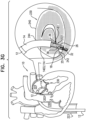
- system 10 comprises an attachment mechanism (e.g., anchor(s), adhesive, clamp(s), clip(s), fastener(s), etc.), such as a plurality of anchors 32, which can be, for example, between about 5 and about 20 anchors, such as about 10 or about 16 anchors.
- Each anchor 32 can comprise a tissue-engaging element 60 (e.g., a helical tissue-engaging element), and a tool-coupling head 62, fixed to one end of the tissue-engaging element.
- tissue-engaging element 60 e.g., a helical tissue-engaging element
- tool-coupling head 62 fixed to one end of the tissue-engaging element.
- One anchor 32 is shown in Fig. 2 as being reversibly coupled to a deployment element 38 of a rotating anchor driver 36 of an anchor deployment manipulator 61.
- Anchors 32 can comprise a biocompatible material, such as stainless steel 316 LVM.
- anchors 32 comprise nitinol.
- anchors 32 are coated fully or partially with a non-conductive material.
- Deployment manipulator 61 as shown in Fig. 2 , comprises anchor driver 36 and deployment element 38.
- sleeve 26 is disposed within a lumen of guide catheter 14.
- a force is applied to a proximal end of sleeve 26 by a distal end of a reference-force tube 19.
- an implant-decoupling channel 18 is advanceable within a lumen of reference-force tube 19 and through a lumen of sleeve 26 such that a portion of channel 18 that is disposed within the sleeve is coaxial with the sleeve.
- a distal end 17 of implant-decoupling channel 18 is disposed in contact with an inner wall of sleeve 26 at a distal end thereof.
- a distal end portion of channel 18 comprises a radiopaque marker 1018.
- tube 19 and sleeve 26 are longitudinally and coaxially disposed with respect to each other.
- sleeve 26 comprises a plurality of radiopaque markers 25, which are positioned along the sleeve at respective longitudinal sites.
- the markers can provide an indication in a radiographic image (such as a fluoroscopy image) of how much of the sleeve has been deployed at any given point during an implantation procedure, in order to enable setting a desired distance between anchors 32 along the sleeve.
- the markers comprise a radiopaque ink.
- the longitudinal sites of the radiopaque markers are longitudinally spaced at a constant interval.
- the longitudinal distance between the distal edges of adjacent markers, and/or the distance between the proximal edges of adjacent markers can be set equal to the desired distance between adjacent anchors.
- the markers can comprise first, second, and third markers, which first and second markers are adjacent, and which second and third markers are adjacent, and the distance between the proximal and/or distal edges of the first and second markers equal the corresponding distance between the proximal and/or distal edges of the second and third markers.
- the distance can be between 3 and 15 mm, such as 6 mm, and the longitudinal length of each marker can be between 0.1 and 14 mm, such as 2 mm. (If, for example, the distance were 6 mm and the length were 2 mm, the longitudinal gaps between adjacent markers would have lengths of 4 mm.)
- Anchor driver 36 comprises an elongate tube having at least a flexible distal end portion.
- the elongate tube of driver 36 extends within a lumen of channel 18, through system 10 toward a proximal end of a proximal handle portion 101 of system 10.
- the tube of anchor driver 36 provides a lumen for slidable advancement therethrough of an elongate rod 130.
- Rod 130 facilitates the locking and unlocking of anchor 32 to deployment element 38, as is described hereinbelow.
- a proximal end of rod 130 is coupled to a component of an anchor-release mechanism 28 at a proximal end of system 10.
- Mechanism 28 comprises a housing 135 and a finger-engager 131 that is coupled to the proximal end of rod 130.
- Finger-engager 131 is coupled to a housing 135 via a spring 133 (section E-E of Fig. 2 ).
- a proximal end of the tube of anchor driver 36 is coupled to housing 135.
- the user e.g., a physician, health care professional, etc.
- anchor driver 36 e.g., rotation and/or proximal-distal movement thereof, and/or release of anchor 32
- anchor driver 36 is electronically controllable, such as by using an extracorporeal controller and/or electric motor coupled to a proximal end of the anchor driver and/or housing 135.
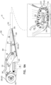
- Proximal handle portion 101 can be supported by a stand having support legs 91 and a handle-sliding track 90.
- Handle portion 101 comprises an outer-catheter handle 22, a guide-catheter handle 24, an implant-manipulating handle 126, and anchor-release mechanism 28.
- Handle 22 is coupled to a proximal end of outer catheter 12.
- Handle 24 is coupled to a proximal portion of guide catheter 14.
- Handle 126 is coupled to a proximal portion of reference-force tube 19, and linear movement of handle 126 with respect to handle 24 moves reference-force tube 19 (and thereby typically structure 222) through catheter 14.
- housing 135 of anchor-release mechanism 28 is coupled to a proximal portion of the tube of anchor driver 36.
- the relative positioning of each of the concentrically-disposed components of system 10 is shown in the exploded view and sections A-A, B-B, C-C, and D-D of Fig. 2 .
- the stand supporting proximal handle portion 101 can be moved distally and proximally to control a position of the entire multi-component system 10, particularly so as to adjust a distance of distal end 102 of catheter 12 from the interatrial septum.
- Handle 22 comprises a steering knob 210 that is coupled to pull wires 29a and 29b disposed within respective secondary lumens in the wall of outer catheter 12. Rotation of knob 210 adjusts a degree of tension of wires 29a and 29b which, in turn, apply a force to pull ring 11 at the distal end portion of outer catheter 12.
- Such force steers the distal end portion of catheter 12 within the atrium of the heart of the patient in a manner in which the distal end portion of catheter 12 is steered in a first plane that is parallel with the plane of the annulus of the valve (e.g., in a direction from the interatrial septum toward surrounding walls of the atrium).
- the distal end portion of catheter 12 can be pre-shaped so as to point downward toward the valve.
- the distal end portion of catheter 12 can be pulled to assume an orientation in which the distal end portion points downward toward the valve.
- the distal end portion of catheter 12 is not made to point downward toward the valve.
- Handle 24 can be coupled to track 90 via a first mount 92.
- Mount 92 can be slidable proximally and distally along track 90 in order to control an axial position of guide catheter 14 with respect to outer catheter 12.
- Mount 92 can be slidable via a control knob 216.
- control knob 216 of mount 92 can control the proximal and distal axial movement of the distal steerable portion of guide catheter 14 with respect to distal end 102 of outer catheter 12.
- Handle 24 can comprise a steering knob 214 that is coupled to pull wires 31a and 31b disposed within respective secondary lumens in the wall of guide catheter 14.
- Rotation of knob 214 adjusts a degree of tension of wires 31a and 31b which, in turn, apply a force to pull ring 13 at the distal end portion of guide catheter 14.
- Such force steers the distal end portion of catheter 14 in a second plane within the atrium of the heart of the patient downward and toward the annulus of the cardiac valve.
- the distal end portion of guide catheter 14 can be steered in the second plane that is substantially perpendicular with respect to the first plane in which the distal end portion of outer catheter 12 is steered.
- handle 22 can be tilted by the user (e.g., an operating physician, etc.), in order to further adjust a position of the distal end of catheter 12.
- handle 22 comprises an indicator that indicates a degree of steering (e.g., bending) of the distal end portion of catheter 12 that has been produced using knob 210.
- handle 24 comprises an indicator that indicates a degree of steering (e.g., bending) of the distal end portion of catheter 12 that has been produced using knob 214.
- first and second couplings 152 and 154 of outer catheter 12 and guide catheter 14, respectively provide a controlled steerable system in which, during the steering and bending of the distal end portion of guide catheter 14, the distal end portion of outer catheter 12 is maintained in its steered configuration, or in its spatial orientation, without substantially affecting the steering or the bending of the distal end portion of guide catheter 14.
- first and second couplings 152 and 154 respectively, minimize the effect of the distal end portion of outer catheter 12 on the steering and bending of catheter 14.
- Contracting member 226 exits from the lumen in the wall of guide catheter 14 at a portion of handle portion 101 that is between handles 22 and 24.
- Handle 126 can be coupled to track 90 via a second mount 93.
- Mount 93 can be slidable proximally and distally along a track, in order to control an axial position of reference-force tube 19 and at least a proximal portion of sleeve 26 with respect to guide catheter 14.
- Mount 93 can be slidable via a control knob.
- the control knob of mount 93 can control the proximal and distal axial movement of the tube 19 and at least the proximal portion of sleeve 26 with respect to distal end 104 of guide catheter 14.
- channel 18 in order to decouple sleeve 26 from a portion of an outer surface of channel 18, (1) channel 18 can be pulled proximally, while (2) reference-force tube 19 is maintained in place. A proximal end of channel 18 can be coupled to a knob 94 which adjusts an axial position of channel 18 proximally and distally with respect to reference-force tube 19 and sleeve 26.
- member 127 In order to release sleeve 26 (e.g., to decouple channel 18 from the sleeve), the user (e.g., an operating physician) must disengage member 127, such as by pushing the button, before continuing to withdraw channel 18 proximally. When engaged, member 127 can also inhibit distal movement of channel 18 with respect to tube 19.
- Handle portion 101 (comprising handles 22, 24, and 126 and anchor-release mechanism 28) can have a length L1 of between 65 and 85 cm, e.g., 76 cm. As shown, a majority of the body portion of outer-catheter handle 22 can be disposed at a non-zero angle with respect to a longitudinal axis 7 of the multiple components of system 10. The steering mechanism provided by handle 22 in order to steer the distal end portion of catheter 12 is disposed within the portion of handle 22 that is disposed at the non-zero angle with respect to axis 7. Handle 22 comprises an in-line tubular portion 21 which is longitudinally disposed in-line along axis 7 and coaxially with respect to handles 24 and 126 and release mechanism 28.
- Tubular portion 21 is shaped so as to define a lumen for inserting guide catheter 14 therethrough and subsequently into the lumen of outer catheter 12.
- Tubular portion 21 has a length L24 of between 7 and 11 cm, e.g., 7 cm. Such spatial orientation of the majority of handle 22 at an angle with respect to axis 7 reduces an overall functional length of handle portion 101.
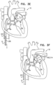
- Annuloplasty structure or annuloplasty ring structure 222 can be used to repair a dilated valve annulus of an atrioventricular valve, such as mitral valve 230.
- the annuloplasty structure is configured to be placed only partially around the valve annulus (e.g., to assume a C-shape), and, once anchored or otherwise secured in place, to be contracted so as to circumferentially tighten the valve annulus.
- the annuloplasty structure is configured to be placed fully around the valve annulus (e.g., to assume a closed shape, such as a circle, oval, D-shape, etc.), and, once secured in place, to be contracted so as to circumferentially tighten the valve annulus.
- the annuloplasty structure can comprise a flexible sleeve 26.
- the annuloplasty structure can also comprise and/or be used with an attachment means (e.g., anchor(s), fastener(s), clamp(s), suture(s), clip(s), etc.), such as a plurality of anchors 32.
- Anchor deployment manipulator 61 is advanced into a lumen of sleeve 26, and, from within the lumen, deploys the anchors through a wall of the sleeve and into cardiac tissue, thereby anchoring the sleeve around a portion of the valve annulus.
- annuloplasty structure or annuloplasty ring structure 222 is implemented using techniques described in US Application No.
- the procedure can begin by advancing a semi-rigid guidewire 202 into a right atrium 220 of the patient.
- the procedure can be performed with the aid of imaging, such as fluoroscopy, transesophageal echo, and/or echocardiography.
- guidewire 202 provides a guide for the subsequent advancement of outer catheter 12 therealong and into the right atrium. Once a distal portion of catheter 12 has entered the right atrium, guidewire 202 is retracted from the patient's body.
- Catheter 12 can comprise a 14-24 F sheath, although any size may be selected as appropriate for a given patient.
- Catheter 12 is advanced through vasculature into the right atrium using a suitable point of origin determined for a given patient. For example:
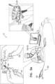
- Catheter 12 can be advanced distally until the sheath reaches the interatrial septum, and guidewire 202 is withdrawn, as shown in Fig. 3C .
- a resilient needle 206 and a dilator are advanced through catheter 12 and into the heart.
- the dilator In order to advance catheter 12 transseptally into left atrium 224, the dilator is advanced to the septum, and needle 206 is pushed from within the dilator and is allowed to puncture the septum to create an opening that facilitates passage of the dilator and subsequently catheter 12 therethrough and into left atrium 224.
- the dilator is passed through the hole in the septum created by the needle.
- the dilator can be shaped to define a hollow shaft for passage along needle 206, and the hollow shaft is shaped to define a tapered distal end.
- This tapered distal end is first advanced through the hole created by needle 206.
- the hole is enlarged when the gradually increasing diameter of the distal end of the dilator is pushed through the hole in the septum.
- a distal end 102 of catheter 12 is tapered so as to facilitate passage of the distal portion of catheter 12 through the opening in the septum.
- the advancement of catheter 12 through the septum and into the left atrium can be followed by the extraction of the dilator and needle 206 from within catheter 12, as shown in Fig. 3E .
- the steerable distal end portion of catheter 12 e.g., a bending section 1203 of catheter 12
- the steerable distal end portion of catheter 12 can be steered in a first plane that is parallel to a plane of the annulus of mitral valve 230.
- Such steering moves the distal end portion of catheter 12 in a direction from the interatrial septum toward surrounding walls of the atrium, as indicated by the arrow in atrium 224.
- steering of the distal portion of catheter 12 can be performed via steering knob 210 of handle 22 in handle portion 101 (in Figs. 1 and 2 ).
- annuloplasty structure or annuloplasty ring structure 222 (not shown for clarity of illustration, with anchor deployment manipulator 61 therein) is advanced through guide catheter 14, which is in turn, advanced through catheter 12 into left atrium 224.
- an exposed distal end portion 114 e.g., a bending section 1403 of catheter 14 extends beyond distal end 102 of catheter 12. Exposed distal end portion 114 is then (1) steered toward the annulus of valve 230 along a plane that is perpendicular with respect to the steering plane of catheter 12 and that is perpendicular with respect to valve 230, and is (2) bent, via bending section 1403 toward valve 230.
- steering of the distal portion of catheter 14 is performed via steering knob 214 of handle 24 in handle portion 101 (in Figs. 1 and 2 ).
- a distal end 251 of sleeve 26 is positioned in a vicinity of a left fibrous trigone 242 of an annulus 240 of mitral valve 230.
- distal end 251 of sleeve 26 is shown schematically in the cross-sectional view of the heart, although left trigone 242 is in reality not located in the shown cross-sectional plane, but rather out of the page closer to the viewer.
- the distal end of sleeve 26 is positioned in a vicinity of a right fibrous trigone 244 of the mitral valve (configuration not shown).
- deployment manipulator 61 deploys a first anchor 32 through the wall of sleeve 26 (by penetrating the wall of the sleeve in a direction in a direction parallel to a central longitudinal axis of deployment manipulator 61, or anchor driver 36, through the distal end of channel 18, and/or parallel to central longitudinal axis of tissue-engaging element 60 of anchor 32) into cardiac tissue near the trigone.
- deployment element 38 is decoupled from anchor 32 by moving rod 130 proximally.
- Anchors 32 can be deployed from a distal end of manipulator 61 while the distal end is positioned such that a central longitudinal axis through the distal end of manipulator 61 forms an angle with a surface of the cardiac tissue of between about 20 and 90 degrees, e.g., between 45 and 90 degrees, such as between about 75 and 90 degrees, such as about 90 degrees.
- Anchors 32 can be deployed from the distal end of manipulator 61 into the cardiac tissue in a direction parallel to the central longitudinal axis through the distal end of manipulator 61. Such an angle can be provided and/or maintained by channel 18 being more rigid than sleeve 26.
- Distal end 17 (shown in Fig.
- pushing of distal end 17 against the cardiac tissue (via the wall of the sleeve) temporarily deforms the cardiac tissue at the site of contact. This deformation can facilitate identification of the site of contact using imaging techniques (e.g., by identifying a deformation in the border between cardiac tissue and blood), and thereby can facilitate correct positioning of the anchor.
- anchors 32 can be deployed from a lateral portion of manipulator 61.
- An indicator (such as indicator 2120 described in PCT patent application PCT/IL2012/050451 to Sheps et al. , which published as WO/2013/069019 ) on handle 126 provides an indication of how much channel 18 is withdrawn from within sleeve 26 (i.e., how much the delivery tool is decoupled from sleeve 26, and how much the sleeve has advanced off channel 18 and against tissue).
- a proximal end of channel 18 is coupled to a knob 94 ( Fig. 2 ) which adjusts an axial position of channel 18 proximally and distally with respect to reference-force tube 19 and sleeve 26.
- deployment manipulator 61 is repositioned along annulus 240 to another site selected for deployment of a second anchor 32. Reference is now made to Figs. 1 and 3H . Such repositioning of manipulator 61 is accomplished by:
- the already-deployed first anchor 32 holds the anchored end of sleeve 26 in place, so that the sleeve is drawn from the site of the first anchor towards the site of the second anchor.
- deployment manipulator 61 can be moved generally laterally along the cardiac tissue, as shown in Fig. 3H .
- Deployment manipulator 61 deploys the second anchor through the wall of sleeve 26 into cardiac tissue at the second site.
- the portion of sleeve 26 therebetween can remain tubular in shape, or can become flattened, which may help reduce any interference of the ring with blood flow.
- deployment manipulator 61 can be repositioned along the annulus to additional sites, at which respective anchors are deployed, until the last anchor is deployed in a vicinity of right fibrous trigone 244 (or left fibrous trigone 242 if the anchoring began at the right trigone).
- the last anchor is not deployed in the vicinity of a trigone, but is instead deployed elsewhere in a vicinity of the mitral valve, such as in a vicinity of the anterior or posterior commissure. Then, system 10 is removed, leaving behind implant structure 222 and contracting member 226.
- a contracting-member-uptake tool is then threaded over and advanced along contracting member 226 and toward structure 222, and is used to contract structure 222 by adjusting a degree of tension of contracting member 226 (not shown in Fig. 3I , but (i) advancing of contracting-member-uptake tool over contracting member 226 is described with reference to Figs. 4A-5D , mutatis mutandis, and (ii) applying tension to member 226 is described hereinbelow with reference to Figs. 6A-B ).
- such an anchor-manipulation tool can comprise an anchor-manipulation tool described in a PCT patent application PCT/IL2013/050861 to Herman et al, titled “Percutaneous tissue anchor techniques", filed on October 23, 2013 .
- Systems, apparatuses, and techniques described in the present patent application can be used in combination with systems, apparatuses, and techniques described in said PCT patent application PCT/IL2013/050861 .
- sleeve 26 of ring structure 222 comprises a plurality of radiopaque markers 25, which are positioned along the sleeve at respective longitudinal sites to indicate anchor-designated target areas.
- the markers can provide an indication in a radiographic image (such as a fluoroscopy image) of how much of sleeve 26 has been deployed at any given point during an implantation procedure, in order to enable setting a desired distance between anchors 32 along the sleeve 26.
- anchors 32 are deployed at longitudinal sites of sleeve 26 at which radiopaque markers 25 are disposed (e.g., the anchors are driven through a radiopaque ink of the radiopaque markers).
- anchors 32 can be deployed at longitudinal sites of sleeve 26 between markers 25.
- a marker 25 at the distal end of channel 18 can indicate that a correct length of sleeve 26 has been dispensed. Subsequent limited movement of the channel with respect to the sleeve may occur.
- the channel when channel 18 is placed against the annulus, the channel may tension the portion of sleeve 26 between the previously-deployed anchor and the distal end of the channel, such that when the anchor is deployed, it passes through the sleeve slightly proximally to the marker 25 (e.g., 1-2 mm proximally to the marker).
- an excess portion of sleeve 26 may be present at the proximal portion of sleeve.
- a cutting tool (not shown) can be advanced within channel 18 and into the lumen of the excess portions of sleeve 26 (e.g., from within sleeve 26) in order to cut the sleeve proximal to the proximal-most-deployed anchor 32.
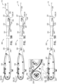
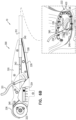
- Figs. 4A-B are schematic illustrations of an example system 10, which is not a part of the invention, comprising an example contracting-member-uptake tool 300 which is configured to contract contracting member 226 and sever any excess portions of contracting member 226.
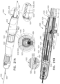
- Tool 300 comprises a handle portion 320 and an elongate sheath 310 coupled thereto. Sheath 310 encases a primary tube 330 and a secondary tube 340 disposed alongside primary tube 330. Both primary tube 330 and secondary tube 340 are coupled to handle portion 320 at respective proximal ends of tubes 330 and 340.
- Secondary tube 340 has a secondary-tube-lumen configured for passage therethrough of contracting member 226.
- Tool 300 defines a longitudinal axis 301.
- sheath 310 is shaped so as to define a lumen in a wall of sheath 310.
- tool 300 does not comprise secondary tube 340, but rather, the lumen in the wall of sheath 310 functions as secondary tube 340 and the primary lumen defined by the wall of sheath 310 functions as primary tube 330.
- Sheath 310, primary tube 330, and secondary tube 340 can be flexible such that sheath 310, primary tube 330, and secondary tube 340 are configured for passage through vasculature of the patient during a transvascular, transcatheter procedure.
- sheath 310, primary tube 330, and secondary tube 340 comprise silicone.
- sheath 310, primary tube 330, and secondary tube 340 comprise polyurethane.
- Tool 300 can comprise a distal end portion 333 having a distal tip 331 which defines a distal end of tool 300.
- Primary tube 330 terminates at distal end portion 333.
- Distal end portion 333 comprises a housing 332 which is shaped so as to hold and be removably coupled to a contracting-member-fastener 360.
- Contracting-member-fastener 360 comprises a clamping structure that can be biased toward assuming a closed state or closed position, and in the closed state/position, the clamping structure can be configured to clamp onto the contracting member 226 passed therethrough (not shown).
- the clamping structure can also be configured such that it can be flexed to an open state through which contracting member 226 (not shown) can move.
- Tool 300 can comprise a fastener-ejector 335 movable within distal end portion 333 of contracting-member-uptake tool 300. Movement of fastener-ejector 335 converts contracting-member-fastener 360 (or clamping structure thereof) from its open state to its closed state to clamp onto contracting member 226 passed therethrough, as will be described hereinbelow.
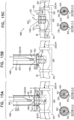
- Tool 300 comprises a stop 362 removably coupled to contracting-member-fastener 360 and configured to maintain contracting-member-fastener 360 in the open state, as shown in Section A-A of Fig. 4A .
- Stop 362 comprises one or more, e.g., two, prongs 337 which maintain fastener 360 in the open state.
- Ejector 335 is coupled to stop 362 and moves stop 362 that is removably coupled to fastener 360 in order to convert fastener 360 from the open state to a closed state, as is described hereinbelow.
- Contracting-member-uptake device 322 can optionally comprise a wheel, which can have two opposing wedged portions 325 which together define a groove 326 configured to couple contracting member 226 to the wheel of device 322.
- Wedged portions 325 can be shaped so as to receive any portion of contracting member 226, e.g., a proximal end of member 226 and/or a middle portion of member 226.
- opposing wedged portions 325 are configured to grip contracting member 226.
- the wheel of device 322 can have a numerical indicator to indicate the number of turns of the wheel.
- Handle portion 320 can be shaped so as to define a lumen 328 for passage therethrough of snare 350 from within the lumen of secondary tube 340.
- Snare 350 passes through lumen 328 and beyond groove 326 of contracting-member-uptake device 322.
- device 322 does not uptake snare 350 but rather, snare 350 passes through groove 326.
- pulling on snare 350 pulls on contracting member 226 coupled thereto such that contracting member 226 is pulled through secondary tube 340, through lumen 328 and ultimately toward contracting-member-uptake device 322.
- contracting member 226 is coupled to contracting-member-uptake device 322 by being fed into groove 326.
- Contracting-member-uptake device 322 is then actuated in order to apply tension to contracting member 226, and thereby to annuloplasty structure 222 implanted along the annulus. With each rotation of the wheel of device 322, successive portions of contracting member 226 are wound within groove 326 of device 322.
- Figs. 5A-D are schematic illustrations of an example contracting-member-uptake tool 300, which is not a part of the invention, useable to uptake contracting member 226.
- annuloplasty structure or annuloplasty ring structure 222 has been implanted along annulus 240, as described hereinabove with reference to Figs. 3A-I .
- contracting member 226 extends away from structure 222 and through vasculature of the patient such that a proximal end portion of member 226 is disposed outside the body of the patient.
- Contracting member 226 can exit sleeve 26 of structure 222 at any suitable location along structure 222.
- contracting member 226 can exit sleeve 26 of structure 222 at a portion of structure 222 in a vicinity of a left fibrous trigone of the valve, as shown.
- contracting member 226 exits sleeve 26 of structure 222 at a portion of structure 222 in a vicinity of a right fibrous trigone of the valve.
- contracting member 226 exits sleeve 26 of structure 222 at a middle portion of structure 222.
- structure 222 comprises sleeve 26 which defines the primary body portion of structure 222.
- Contracting member 226 has a first portion 420 extending along a longitudinal length of the primary body portion of annuloplasty structure 222. The first portion 420 can extend along the longitudinal length of structure 222 when structure 222 is in a linear state as well as in a curved state, as shown in Fig. 5A . Contracting member 226 also defines a second portion 422 extending away from the primary body portion of annuloplasty structure 222.
- the user e.g., an operating physician, etc.
- the user can hold a distal end of tool 300 in one hand and a proximal end portion of contracting member 226 in another hand.
- the user or physician threads the proximal end portion of contracting member 226 through distal snare portion 352 of contracting-member-snare 350.
- Fig. 5B shows tool 300 in a state in which distal snare portion 352 ensnares contracting member 226.
- distal snare portion 352 is shaped so as to increase the coupling between snare 350 and contracting member 226.
- distal snare portion 352 is corrugated to increase friction between snare portion 352 and contracting member 226.
- distal snare portion 352 can comprise a coiled section to increase friction between snare portion 352 and contracting member 226.
- snare 350 comprises a metal wire.
- snare 350 comprises a metal wire comprising stainless steel.
- Snare 350 (including distal snare portion 352) can have a variety of sizes, for example, a diameter of 0.15-0.5 mm or 0.15-0.35 mm.
- Figs. 4A and 5B As shown in Section A-A of Fig. 4A , contracting-member-snare 350 passes through aligned ports 339 and 341 in distal end portion 333 of tool 300.
- Snare 350 can be pulled proximally, e.g., by the user or physician holding the proximal exposed end portions 351 of snare 350 proximally away from tool 300. Pulling on snare 350 proximally, as shown in Fig. 5C , pulls distal snare portion 352 and contracting member 226 looped therethrough through distal tip 331 of tool 300, through the fastener disposed within distal end portion 333 of tool 300, through aligned ports 339 and 341 in distal end portion 333 of tool 300, and subsequently, through the lumen of secondary tube 340.
- Snare 350 is pulled until distal snare portion 352 enters the lumen of secondary tube 340.
- the looped portion of distal snare portion 352 is compressed and collapses around contracting member 226 looped therethrough, in order to maintain coupling between snare portion 352 and contracting member 226 as elongate flexible body portion 354 (shown in Fig. 5B ) is pulled through the lumen of secondary tube 340.
- the looped portion of snare portion 352 collapses within the lumen of secondary tube 340, the portion of contracting member 226 ensnared by snare portion 352 bends, and coupling between contracting member 226 and snare portion 352 is strengthened. This strengthening is also brought about as a result of the relatively small diameter of secondary tube 340 of 0.5-1.0 mm.
- snare 350 is pulled entirely through secondary tube 340, through lumen 328 of handle portion 320 and beyond groove 326 of contracting-member-uptake device 322 in order to pull contracting member 226 along this path. All the while, sheath 310 of tool 300 is advanced through vasculature and toward annuloplasty structure 222 implanted along annulus 240 of the valve. Once distal snare portion 352 and the portion of contracting member 226 coupled thereto exit lumen 328 of handle portion 320, the portion of contracting member 226 is coupled to contracting-member-uptake device 322 by being positioned within groove 326. For some applications, the proximal end portion of contracting member 226 is fed within groove 326.
- a middle portion of contracting member 226 (e.g., a portion in a vicinity of the proximal end of contracting member 226) is fed within groove 326.
- Contracting member 226 is then tightened by actuating, e.g., rotating, contracting-member-uptake device 322 such that successive portions of contracting member 226 are wound within contracting-member-uptake device 322 and contracting-member-uptake device 322 uptakes the successive portions.
- snare 350 Once snare 350 has been pulled through tool 300, snare 350 can be discarded.
- tension meter 324 of handle portion 320 reads a tension of contracting member 226 at zero or close to zero.
- sleeve 26 of annuloplasty structure 222 coupled to annulus 240 is in a relaxed, non-tense state.
- tool 300 has been sufficiently advanced through vasculature of the patient such that distal tip 331 is in proximity to structure 222 disposed along the annulus, while a proximal portion of contracting member 226 is disposed outside the body of the patient.
- Fig. 7A shows annuloplasty structure or annuloplasty ring structure 222 in a non-contracted state.
- Distal tip 331 of tool 300 can be brought close to structure 222.
- Contracting member 226 can be threaded along sleeve 26 and out of a portion of sleeve 26 of structure 222. As described hereinabove, contracting member 226 can be threaded through tool 300 in a manner in which member 226 passes through distal tip 331, through contracting-member-fastener 360 that can be held in the open state, such as by prongs 337 of stop 362, through aligned ports 339 and 341 in distal end portion 333 of tool 300, and through secondary tube 340.
- Fig. 7C contracting member 226 has been pulled tight, and annuloplasty structure 222 has been contracted and in a tense, contracted state. Distal end portion 333 of tool 300 is then used to eject and deploy fastener 360 from within tool 300 in order to lock structure 222 in the contracted state.
- Fastener-ejector 335 is coupled to prongs 337 of stop 362 in a manner in which when ejector 335 is moved proximally within portion 333, stop 362 is decoupled from contracting-member-fastener 360 as prongs 337 move proximally away from contracting-member-fastener 360. Once contracting-member-fastener 360 is no longer held in the open state by stop 362, fastener 360 closes, as it tends to do, and clamps around contracting member 226 passing therethrough.
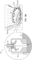
- FIGs. 8A-D are schematic illustrations of an example of a system 510, which is not a part of the invention, for contracting annulus 240 of the patient using an annuloplasty structure 522 (e.g., an annuloplasty ring structure, a closed annuloplasty structure, a closed annuloplasty ring structure, an open annuloplasty structure, a partial annuloplasty ring structure, etc.), which can comprise a housing 530.
- Housing 530 can house a contracting-member-fastener 360.
- annuloplasty structure 522 can be the same as or generally similar to annuloplasty structure 222, described hereinabove with reference to Figs. 1-7E and like reference numerals refer to like parts.
- Annuloplasty structure or annuloplasty ring structure 522 is implanted as described hereinabove with reference to Figs. 3A-I using the system described hereinabove with reference to Figs. 1-3I .
- Housing 530 can be coupled to sleeve 26 of structure 522 at any suitable location along structure 522.
- housing 530 can be coupled to sleeve 26 of structure 522 at a portion of structure 522 in a vicinity of a left fibrous trigone of the valve, as shown.
- housing 530 can be coupled to sleeve 26 of structure 522 at a portion of structure 522 in a vicinity of a right fibrous trigone of the valve.
- housing 530 can be coupled to sleeve 26 of structure 522 at a middle portion of structure 522.
- housing 530 can be coupled to a lateral surface of sleeve 26. In such applications, housing 530 does not block them lumen of sleeve 26 of structure 522.
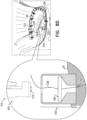
- Fig. 8B shows a contracting-member-uptake tool 600 through which contracting member 226 has been threaded.
- Contracting member 226 can be ensnared by tool 600 using a snare as described herein above with regard to snare 350 with reference to Figs. 4A-5D .
- Tool 600 can be advanced along contracting member 226 toward housing 530 of structure 522, in a manner similar to tool 300 advancing along contracting member 226, as described hereinabove with reference to Figs. 4A-5D .
- Tool 600 can comprise a distal tip 631 and a distal end portion 633 which is generally similar to distal end portion 533 of tool 300, described hereinabove with reference to Figs. 4A-7E and like reference numerals refer to like parts. Since annuloplasty structure 522 comprises contracting-member-fastener 360 and stop 570 removably coupled to fastener 360, distal end portion 633 of tool 600 is unlike distal end portion 533 of tool 300 of Figs. 4A-7E , remaining parts of tool 600 correspond to the remaining parts of tool 300.
- contracting-member-uptake tool 702 can be the same as or generally similar to contracting-member-uptake tools 300 and 600, described hereinabove with reference to Figs. 4A-9D , used to (1) apply tension to the contracting member, (2) deploy a lock in order to secure tension of the contracting member, and (3) subsequently cut and sever the contracting member of any annuloplasty structure, e.g., a full (or closed) annuloplasty ring structure or a partial (or open) annuloplasty ring structure.
- any annuloplasty structure e.g., a full (or closed) annuloplasty ring structure or a partial (or open) annuloplasty ring structure.
- structure 730 comprises sleeve 26 which defines the primary body portion of structure 730.
- Contracting member 226 has a first portion 732 extending along a longitudinal length of the primary body portion of annuloplasty structure 730. Contracting member 226 also defines a second portion 734 extending away from the primary body portion of annuloplasty structure 730.
- annuloplasty structure 730 is implemented using techniques described in US Application No. 12/341,960, filed December 22, 2008 , which issued as US 8,241,351 , US Application No. 12/437,103, filed May 7, 2009 which issued as US 8,715,342 , and/or US Application No. 12/689,635, filed January 19, 2010 which published as US 8,545,553 , both of which are assigned to the assignee of the present application.
- Tool 702 is used to deploy one or more (e.g., two as shown) contracting-member-fasteners 360a and 360b.
- Fasteners 360a and 360b are similar to or the same as fasteners 360 described hereinabove with reference to Figs. 4A-9D .
- the use of two fasteners 360a and 360b can provide redundant and more secure fastening of a perimeter of structure 730 following contraction thereof.
- Fasteners 360a and 360b can be disposed coaxially around a portion of contracting member 226
- tool 702 is used to sever any excess portions of contracting member 226, as described hereinbelow with reference to tools 300 and 600 as described hereinabove with reference to Figs. 4A-9D .
- oversheath 710 is not used and tool 702 is coupled to the annuloplasty structure using male and female couplings, as shown hereinbelow with reference to Figs. 12 , 13 , and 15 .
- contracting-member-uptake tool 810 can be the same as or generally similar to contracting-member-uptake tools 300 and 600, described hereinabove with reference to Figs. 4A-9D , used to (1) apply tension to the contracting member, (2) deploy a lock in order to secure tension of the contracting member, and (3) subsequently cut and sever the contracting member of any annuloplasty structure, e.g., a full (or closed) annuloplasty ring structure, a partial (or open) annuloplasty structure, etc.
- any annuloplasty structure e.g., a full (or closed) annuloplasty ring structure, a partial (or open) annuloplasty structure, etc.
- Fig. 11A shows annuloplasty structure or annuloplasty ring structure 222 in a non-contracted state.
- Distal tip 331 of tool 810 can be brought close to structure 222.
- Contracting member 226 can be threaded along sleeve 26 and out of a portion of sleeve 26 of structure 222. As described hereinabove, contracting member 226 can be threaded through tool 810 in a manner in which member 226 passes through distal tip 331, through contracting-member-fastener 360 that can be held in the open state, such as by prongs 337 of stop 362, through aligned ports 339 and 341 in distal end portion 333 of tool 810, and through secondary tube 340.
- the distal end portion of tool 810 is similar to the distal end portion of tool 702 as described hereinabove with reference to Figs. 10A-B .
- the distal end portion of tool 810 is similar to the distal end portion of tool 920 as shown hereinbelow with reference to Figs. 12 , 13 , and 15 .
- tool 920 comprises male coupling 925 and annuloplasty structure 222 comprises housing 930 shaped so as to define female coupling 927.
- Tool 810 comprises a proximal handle portion 820.
- Handle portion 820 comprises a proximal contraction-facilitating knob 830.
- Knob 830 is fixedly coupled to a proximal end 832 of contracting member 226.
- Rotation of contraction-facilitating knob 830 as shown in Fig. 11A moves knob 830 proximally.
- contracting member 226 is pulled proximally.
- annuloplasty structure 222 is contracted.
- Tool 810 comprise a gauge 834 indicating a level of contraction of the ring responsively to the number of rotations of knob 830.
- tool 810 can be used to contract structure 222 by tool 810 pulling on contracting member 226 responsively to rotation of the knob 830 as described hereinabove with reference to Fig. 11A .
- fastener 360 is not deployed.
- Fig. 11C contracting member 226 has been pulled tight, and annuloplasty structure 222 has been contracted and in a tense, contracted state. Distal end portion 333 of tool 810 is then used to eject and deploy fastener 360 from within tool 810 in order to lock structure 222 in the contracted state.
- Proximal movement of trigger knob 840 pulls proximally on actuating wire 842, which, in turn, pulls maximally fastener-ejector 335. Movement of fastener-ejector 335 proximally converts contracting-member-fastener 360 from its open state to its closed state to clamp onto contracting member 226 passed therethrough.
- Fastener-ejector 335 is coupled to prongs 337 of stop 362 in a manner in which when ejector 335 is moved proximally within portion 333, stop 362 is decoupled from contracting-member-fastener 360 as prongs 337 move proximally away from contracting-member-fastener 360. Once contracting-member-fastener 360 is no longer held in the open state by stop 362, fastener 360 closes, as it tends to do, and clamps around contracting member 226 passing therethrough.
- Actuating wire 842 is disposed within an inner sheath 841 which runs the length of elongate sheath 310.
- elongate sheath 310 comprises a multi-lumen sheath defining (1) a first lumen for passage therethrough of inner sheath 841 housing within it actuating wire 842, and (2) a second lumen for passage therethrough of contracting member 226.
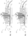
- fastener 360 has been ejected and deployed from within housing 332 of ejector 335. Subsequently, fastener-ejector 335 is moved further proximally in response to the further pulling proximally of trigger knob 840, in order to sever excess portions of contracting member 226.
- tool 810 is shaped so as to define a cutting-facilitating edge 370 in distal end portion 333 of tool 810. For some applications, cutting-facilitating edge 370 defines a sharp edge. While contracting member 226 passes through aligned ports 339 and 341 in distal end portion 333 of tool 810, as shown in Figs.
- tool 810 is removed from the body of the patient by being withdrawn proximally, bringing together with it the excess portion of contracting member 226.
- FIGs. 12A-C are schematic illustrations of an example of a system 900, which is not a part of the invention, comprising an example annuloplasty structure 910 (e.g., an annuloplasty ring structure, a closed annuloplasty structure, a closed annuloplasty ring structure, an open annuloplasty structure, a partial annuloplasty ring structure, etc.) comprising a sleeve 26, a contracting member 226, and a lock 950.
- Implantable annuloplasty structure 910 comprises a primary body portion 912.
- Contracting member 226 has a first portion 914 extending along a longitudinal length of primary body portion 912 of annuloplasty structure 910, and a second portion 916 extending away from primary body portion 912 of annuloplasty structure 910. Contracting member 226 is configured to adjust a perimeter of annuloplasty structure 910.
- annuloplasty structure 910 can be the same as or generally similar to annuloplasty structures 222, 522, and 730 described hereinabove with reference to Figs. 1-11C and like reference numerals refer to like parts.
- Annuloplasty structure 910 can be a full (or closed) or partial (or opened) annuloplasty structure.
- Primary body portion 912 of structure 910 has a lateral wall and is shaped so as to define a recess 960 having a recess axis 940.
- Recess 960 extends from an opening 932 in a first surface 934 of the lateral wall of primary body portion 912 toward an opposite second surface 936 of the lateral wall of the primary body portion 912 (illustrated in Fig 12C ).
- the lateral wall of primary body portion 912 extends away from recess 960 along a longitudinal axis 942 that is at a non-zero angle with respect to recess axis 940.
- Contracting member 226 extends through recess 960 and away from primary body portion 912 of annuloplasty structure 910 via recess 960.
- Recess 960 is shaped so as to define a recess lumen 962.
- Recess lumen 962 is disposed along recess axis 940.
- primary body portion 912 comprises a housing 930 coupled to sleeve 26.
- housing 930 defines at least a portion of the lateral wall and housing 930 defines recess 960.
- Sleeve 26 defines the remaining portion of the lateral wall.
- structure 910 does not comprise a housing 930, and sleeve 26 defines the lateral wall.
- Recess 960 is shaped so as to receive lock 950. Recess 960 is dimensioned so as to compress lock 950 when lock 950 is disposed at least in part within recess 960.
- Lock 950 is shaped to as to define a series of tapered segments 951. Each segment 951 having a longest length L1 of 0.2-1.5 mm. A proximal-most section of lock 950 has a length L2 of 0.2-2 mm.
- recess 960 corresponds to the shape of lock 950 and is slightly smaller than the shape of lock 950 such that the walls that define recess 960 compress lock 950 as it slides into recess 960. That is, the section of recess 960 that receives longest length L1 of segment 951 has a longest length L3 of 0.2-1.5 mm. A proximal-most section of recess 960 has a length L4 of 0.2-2 mm.
- Lock 950 is shaped so as to define a lock lumen configured to surround contracting member 226.
- Lock 950 is shaped so as to define a longitudinal slit 952 which extends from a proximal surface of lock 950 toward a distal surface of lock 950.
- slit 952 defines the lock lumen of lock 950. Slit 952 enables lock 950 to squeeze into the smaller recess 960 and thereby be compressed.
- slit 952 enables lock 950 to close around contracting member 226 and thereby lock 950 to contracting member 226.
- the lock lumen has a dimension (e.g., a diameter) that is consistent along a length of the lock lumen from the proximal surface of lock 950 to a distal surface of lock 950.
- Lock-ejector 923 is movable within a distal end portion of tool 920. Movement of lock-ejector 923 contacts and converts lock 950 from an open state (shown in Fig. 12A ) to a closed state (shown in Fig. 12C ) in order to clamp lock 950 onto contracting member 226 passed therethrough.
- lock 1950 is disposed at least in part and retained within recess a 1960.
- a distal-most tapered segment 951 is disposed within a proximal section of recess 1960. In such a manner, system 1000 reduces the possibility of embolism and/or clotting.
- a delivery tool can be used to deliver lock 1110 toward the annuloplasty structure or annuloplasty ring structure.
- the delivery tool can be the same as or generally similar to tools 300, 600, 702, 810, and 920 described hereinabove with reference to Figs. 4A-13C and like reference numerals refer to like parts.
- the delivery tool comprises a contracting-member severing section which can comprise elements of tools 300, 600, 702, 810, and 920 described hereinabove with respect to the cutting elements.
- FIGs. 15A-C are schematic illustrations of an example system 1480 comprising an example annuloplasty structure 910 (e.g., an annuloplasty ring structure, a closed annuloplasty structure, a closed annuloplasty ring structure, an open annuloplasty structure, a partial annuloplasty ring structure, etc.) comprising a sleeve 26, a contracting member 226, and a lock 1490, in accordance with some applications.
- system 1480 is the same or generally similar to system 1000 as described hereinabove with reference to Figs. 13A-C with the exception that lock 1490 has a lumen that is narrower at the proximal end portion of lock 1490 and wider at the distal end portion of lock 1490.
- Section A-A of Fig. 15A shows the lock lumen being wider around contracting member 226 at the proximal end portion of lock 1490 than a width of the lock lumen around contracting member 226 at the distal end portion of lock 1490 shown in Section B-B.
- Fig. 15C once lock 1490 is disposed entirely within recess 960, the proximal end portion closes tightly around contracting member 226, as shown in Section C-C, while the distal end portion closes around contracting member 226, which may not close as tightly as the proximal end portion closes around contracting member 226, as shown in Section D-D.
- FIG. 16 is a schematic illustration of an example system 1200, which is not a part of the invention, comprising an example annuloplasty structure 1210 (e.g., an annuloplasty ring structure, a closed annuloplasty structure, a closed annuloplasty ring structure, an open annuloplasty structure, a partial annuloplasty ring structure, etc.) comprising a sleeve 26, a contracting member 226, and a lock 1220.
- Implantable annuloplasty structure 1210 comprises a primary body portion.
- Contracting member 226 has a first portion extending along a longitudinal length of the primary body portion of annuloplasty structure 1210, and a second portion extending away from the primary portion of annuloplasty structure 1210. Contracting member 226 is configured to adjust a perimeter of annuloplasty structure 1210.
- Lock 1220 is shaped so as to define a lock lumen 1221 configured to surround contracting member 226.
- Lock 1220 is shaped so as to define a longitudinal slit which extends from a proximal surface of lock 1220 toward a distal surface of lock 1220.
- the slit defines lock lumen 1221 of lock 1220. The slit enables lock 1220 to squeeze into the smaller recess 1230 and thereby be compressed. When lock 1220 is compressed, the slit enables lock 1220 to close around contracting member 226 and thereby lock 1220 to contracting member 226.
- lock lumen 1221 has a dimension (e.g., a diameter) that is consistent along a length of lock lumen 1221 from the proximal surface of lock 1220 to a distal surface of lock 1220.
- lock lumen 1221 of lock 1220 is shaped so as to define a distal portion that is wider than a proximal portion of lock lumen 1221.
- the proximal-most section of recess 1230 can be narrower than any other portion of recess 1230 distal to the proximal-most portion.
- annuloplasty structure 1310 can be the same as or generally similar to annuloplasty structures 222, 522, 730, and 910 described hereinabove with reference to Figs. 1-15C and like reference numerals refer to like parts.
- Annuloplasty structure 1310 can be a full (or closed) or partial (or opened) annuloplasty structure.
- recess-distal-tapered-portion 1324 is configured to compress lock-distal-tapered-portion 1334 which, in turn, is configured to pinch a second portion of contracting member 226 within lock lumen 1321 at recess-distal-tapered-portion 1324 in order to lock contracting member 226 at least a second pinching point 1314.
- Systems 1200 and 1300 provide a locking assembly which allows for the operating physician to readjust the perimeter of the annuloplasty structure post-locking. For example, if the physician would like to readjust once locks 1220 and 1320 are in place, the physician is able to unscrew locks 1220 and 1230 respectively in order to readjust the perimeter of the annuloplasty structure by giving slack to or tightening contracting member 226 without disengaging locks 1220 and 1300 from the respective recess 1230 and 1330. Subsequently to the readjusting of contracting member 226, locks 1220 and 1320 are repositioned within the respective recess 1230 and 1330.
- FIG. 18 is a schematic illustration of an example of a system 1350, which is not a part of the invention, for contracting annulus 240 of the patient using an annuloplasty structure 522 (e.g., an annuloplasty ring structure, a closed annuloplasty structure, a closed annuloplasty ring structure, an open annuloplasty structure, a partial annuloplasty ring structure, etc.), which can comprise a housing 530.
- Housing 530 can house a contracting-member-fastener 1360.
- annuloplasty structure 522 can be the same as or generally similar to annuloplasty structure 222, described hereinabove with reference to Figs. 1-7E and like reference numerals refer to like parts.
- Annuloplasty structure or annuloplasty ring structure 522 is implanted as described hereinabove with reference to Figs. 3A-I using the system described hereinabove with reference to Figs. 1-3I .
- Housing 530 can be coupled to sleeve 26 of structure 522 at any suitable location along structure 522.
- housing 530 can be coupled to sleeve 26 of structure 522 at a portion of structure 522 in a vicinity of a left fibrous trigone of the valve, as shown.
- housing 530 can be coupled to sleeve 26 of structure 522 at a portion of structure 522 in a vicinity of a right fibrous trigone of the valve.
- housing 530 can be coupled to sleeve 26 of structure 522 at a middle portion of structure 522.
- housing 530 can be coupled to a lateral surface of sleeve 26. In such applications, housing 530 does not block them lumen of sleeve 26 of structure 522.
- Housing 1430 can be coupled to the sleeve 26 of the annuloplasty structure at any suitable location along the annuloplasty structure.
- housing 1430 can be coupled to the sleeve 26 of the annuloplasty structure at a portion of the annuloplasty structure in a vicinity of a left fibrous trigone of the valve, as shown.
- housing 1430 can be coupled to the sleeve of the annuloplasty structure at a portion of the annuloplasty structure in a vicinity of a right fibrous trigone of the valve.
- housing 1430 can be coupled to the sleeve of the annuloplasty structure at a middle portion of the annuloplasty structure.
- housing 1430 can be coupled to a lateral surface of the sleeve. In such applications, housing 1430 does not block them lumen of the sleeve of the annuloplasty structure.
- Fastener 1460 is shaped so as to define a generally-rectangular, planar clip comprising a super-elastic material, e.g., nitinol.
- Fastener 1460 comprises a deformable element shaped so as to define a plurality of slits which are surrounded by a plurality of flexible legs 1462 which enable the clip to transition between slanted ( Fig. 19A ) and straight ( Fig. 19B ) states.
- the contracting-wire-engaging surface of the clip is shaped to define a plurality of teeth 1464. For some applications, teeth 1464 are jagged. For some applications, the upper surface of the clip does not comprise teeth 1464 and is flat. Teeth 1464 are configured to increase friction between contracting member 226 and fastener 1460.
- System 1500 is used to contract the annulus of the patient using annuloplasty structure 1522 (e.g., an annuloplasty ring structure, a closed annuloplasty structure, a closed annuloplasty ring structure, an open annuloplasty structure, a partial annuloplasty ring structure, etc.), which can comprise a housing 1530.
- Housing 1530 can house a contracting-member-fastener 1560.
- annuloplasty structure 1522 can be the same as or generally similar to annuloplasty structure 222, described hereinabove with reference to Figs. 1-7E and like reference numerals refer to like parts.
- Annuloplasty structure or annuloplasty ring structure 1522 is implanted as described hereinabove with reference to Figs. 3A-I using the system described hereinabove with reference to Figs. 1-3I .
- Fig. 20A shows contracting-member-severing tool 1502 through which contracting member 226 has been threaded.
- Contracting member 226 can be ensnared by tool 1502 using a snare as described herein above with regard to snare 350 with reference to Figs. 4A-5D .
- Tool 1502 can be advanced along contracting member 226 toward housing 1530 of structure 1522, in a manner similar to tool 300 advancing along contracting member 226, as described hereinabove with reference to Figs. 4A-5D .
- contracting member 226 extends from sleeve 26, through engager 1574, through the proximal portion of stop 1570, through cutting elements 1510 and 1520 of tool 1502, and through the remaining proximal portion of tool 1502. As such, contracting member 226 is disposed in a vicinity of the cutting elements. Contracting member 226 is disposed along a longitudinal axis 1511 of tool 1502 along the entire length of tool 1502. The relative spatial orientation of the components of tool 1502 enable contracting member 226 to pass straightly and directly though the lumen of tool 1502 and along axis 1511 without taking a winding path through tool 1502.
- Tool 1502 comprises a static cutting element 1510 and a moveable, dynamic cutting element 1520.
- Static cutting element 1510 is shaped so as to define a concave cutting surface 1512 (i.e., a sharp edge)
- dynamic cutting element 1520 is shaped so as to define a concave cutting surface 1521 (i.e., a sharp edge) which opposes concave cutting surface 1512 of static cutting element 1510.
- dynamic cutting element 1520 slides proximally and diagonally with respect to static cutting element 1510, along concave cutting surface 1512 of static cutting element 1510.
- outer sleeve portion 1508 prevents radial movement of graspers 1505 responsively to application of a proximal pulling force to stop 1570 by tool 1502 during the release of fastener 1560 in order to lock contracting member 226 in place and retain annuloplasty structure 1522 in a tensed state, as will be described hereinbelow.
- Outer sleeve portion 1508 thus locks graspers 1505 with respect to overhang 1572 and provides a secondary coupling and locking of tool 1502 to housing 1530.
- Multi-component tubular system 1500 is used with an implant comprising an implantable structure and flexible elongated contracting member 226 that extends away from the implantable structure.
- the implant may comprise any of the implants described herein, such as implantable annuloplasty structure 222, which may, for example, comprise flexible sleeve 26.
- the implant may comprise another implant known in the art (including those described in the patents and patent application publications referred to hereinbelow), which may or may not comprise a sleeve.
- Contracting-member-uptake tool 1600 comprises a handle portion 1620, which optionally may be supported by a stand, such as described hereinabove with reference to Figs. 1-2 .
- Handle portion 1620 can comprise one, some, or all of:
- Handle portion 1620 is shaped so as to define a handle contracting-member-receiving channel 1650 from a distal end through to a proximal end of handle portion 1620 (as used in the present application, including in the claims, "proximal” means toward the user, i.e., away from the implant; with reference to Figs. 21A-26B , "proximal” means to the right in the drawings).
- Handle contracting-member-receiving channel 1650 includes inner-shaft contracting-member-receiving channel 1638, distal-force-applicator contracting-member-receiving channel 1644, and optionally additional contracting-member-receiving channels of handle portion 1620.
- a portion of contracting member 226 is threaded through handle contracting-member-receiving channel 1650 either after or before the implantable structure and contracting member 226 are advanced toward the heart of the patient.
- Inner shaft 1636 can comprise a lock 1640, which is configured (i) when in an unlocked state, to allow sliding of contracting member 226 with respect to inner-shaft contracting-member-receiving channel 1638, and (ii) when in a locked state, to axially lock contracting member 226 with respect to inner shaft 1636.
- lock 1640 applies friction to axially lock contracting member 226 with respect to inner shaft 1636,such as using a set screw or a lever, as is known in the art.
- Handle portion 1620 is configured such that actuation of contraction-facilitating knob 1630, when contracting member 226 is disposed passing entirely through handle contracting-member-receiving channel 1650 and lock 1640 is in the locked state, causes handle portion 1620 to uptake successive portions of contracting member 226.
- Figs. 22A-B show handle portion 1620 before actuation of contraction-facilitating knob 1630, when contracting member 226 is disposed passing entirely through handle contracting-member-receiving channel 1650 and lock 1640 is in the locked state.
- Figs. 23A-B , 24A-B , and 25A-B show handle portion 1620 after successive levels of actuation of contraction-facilitating knob 1630, as described below.
- the portion of contracting member 226 between handle portion 1620 and the implant may be somewhat slack or at most minimally tensed.
- a proximal end 1652 of tubular shaft 1634 and a proximal end 1654 of inner shaft 1636 are disposed at an initial offset distance D1 therebetween, indicative of essentially no tension in contracting member 226, i.e., that contracting member 226 is not tensed.
- the implant comprises implantable annuloplasty structure 222, which comprises flexible sleeve 26, sleeve 26 (coupled to annulus 240) is in a relaxed, non-tense state. At this point, the tool has been sufficiently advanced through vasculature of the patient such that the distal tip of the tool is in proximity to structure 222 disposed along the annulus.
- contraction-facilitating knob 1630 can cause handle portion 1620 to uptake successive portions of contracting member 226 by:
- contracting member 226 is relatively slack, as mentioned above, such that inner shaft 1636 offers no or relatively little resistance to the proximally-directed force applied to inner shaft 1636 by spring 1646, and spring 1646 is not, or is only minimally, axially compressed.
- inner shaft 1636 advances proximally with respect to the outer housing 1632 to the same, or approximately the same, extent as the tubular shaft 1634 advances proximally with respect to the outer housing 1632, and the offset distance remains at its initial value (D1), indicating that there is still essentially no tension in contracting member 226.
- This initial proximal advancement of tubular shaft 1634 and inner shaft 1636 with respect to outer housing 1632 serves to accommodate differing initial levels of slack in contracting member 226.
- contracting member 226 becomes tensed (at an initial low level of tension), such that inner shaft 1636 gradually offers increasing resistance to the proximally-directed force applied to inner shaft 1636 by spring 1646, and spring 1646 becomes gradually more compressed.
- contracting member 226 is considered to be "tensed” even when tensed at a low level of tension.
- the offset distance between proximal end 1652 of tubular shaft 1634 and proximal end 1654 of inner shaft 1636 decreases to a tensed offset distance D2, as shown in Figs. 24A-B .
- the tensed offset distance D2 is less than the initial offset distance D1, reflecting the fact that the portion of inner shaft 1636 that protrudes from proximal end 1652 of tubular shaft 1634 has decreased.
- Contraction-facilitating knob 1630 can have any shape that enables actuation thereof, and is not necessarily round, tubular, or generally cylindrical.
- contraction-facilitating knob 1630 is configured to be actuated by rotation thereof, e.g., about a central longitudinal axis of tubular shaft 1634, such as shown in the drawings.
- contraction-facilitating knob 1630 is configured to be actuated by axially sliding thereof with respect to outer housing 1632 (configuration not shown).
- Contraction-facilitating knob 1630 can be non-electrical, i.e., entirely mechanical, or may optionally comprise electrical components, including, for example, circuity.
- tubular shaft 1634 and contraction-facilitating knob 1630 are in threaded connection with each other, and handle portion 1620 is configured such that actuation of contraction-facilitating knob 1630 rotates tubular shaft 1634, thereby advancing tubular shaft 1634 proximally with respect to outer housing 1632.
- contraction-facilitating knob 1630 is configured to be actuated by rotation thereof, e.g., about the central longitudinal axis of tubular shaft 1634, such as shown in the drawings.
- handle portion 1620 further comprises an inner stabilization tube 1680, which (a) extends proximally from and is axially fixed to distal force applicator 1642 and (b) defines therethrough a portion of handle contracting-member-receiving channel 1650.
- a portion of inner stabilization tube 1680 is disposed within inner-shaft contracting-member-receiving channel 1638; the length of the portion varies with the distance between distal force applicator 1642 and inner shaft 1636.
- Spring 1646 can be configured to surround a portion of inner stabilization tube 1680 and be free to move axially with respect to the outer surface of inner stabilization tube 1680.
- inner shaft 1636 partially protrudes out of a proximal end 1639 of outer housing 1632, such that a portion of inner shaft 1636 is visible to the user.
- tubular shaft 1634 and inner shaft 1636 together provide a non-electrical mechanical force gauge 1624, in which a relative axial position of tubular shaft 1634 with respect to inner shaft 1636 (i.e., the offset distance D between proximal end 1652 of tubular shaft 1634 and proximal end 1654 of inner shaft 1636) provides a visual indication of a measure of the tension in contracting member 226.
- Tubular shaft 1634 at least after it begins advancing proximally, can also protrude out of proximal end 1639 of outer housing 1632.
- inner shaft 1636 can be marked with a plurality of fiduciary markers 1626, which are arranged along inner shaft 1636 to indicate the relative axial position of the tubular shaft 1634 with respect to the inner shaft 1636.
- fiduciary markers 1626 may provide a reading of zero or close to zero when proximal end 1652 of tubular shaft 1634 and proximal end 1654 of inner shaft 1636 are disposed as the initial offset distance D1 therebetween, as shown in Figs. 22A-B . (The force applied to spring 1646 at any given level of compression of the spring equals the tension in contracting member 226.)
- force gauge 1624 does not measure the length of contracting member 226 that handle portion 1620 uptakes. (This uptake length is equal to the distance that inner shaft 1636 moves proximally.) As discussed above, an initial portion of the uptake length is sometimes due to proximal movement of inner shaft 1636 while tubular shaft 1634 proximally moves approximately in tandem with inner shaft 1636 before contracting member 226 is tensed. During this optional initial motion, tension in contracting member 226 does not materially increase, even though handle portion 1620 uptakes contracting member 226.
- inner shaft 1636 can be considered an axially-movable portion of force gauge 1624.
- the axially-movable portion of force gauge 1624 is axially-movable with respect to the outer housing 1632 (and, often, with respect to one or more other portions of force gauge 1624, which themselves may or may not be axially movable with respect to outer housing 1632).
- inner shaft 1636 does not protrude out of proximal end 1639 of the outer housing 1632, in which case handle portion 1620 does not provide non-electrical mechanical force gauge 1624.
- Handle portion 1620 may nevertheless still be entirely useful for regulating the tension in contracting member 226, such as is configurations in which handle portion 1620 further comprises tension-limiting locking assembly 1658 for limiting the maximum tension that inner shaft 1636 can apply to contracting member 226, as described hereinbelow.
- Figs. 24A-B and 25A-B are schematic illustrations of a portion of outer housing 1632 and tubular shaft 1634, in accordance with some applications.
- inner shaft 1636 is not shown.
- handle portion 1620 further comprises a tension-limiting locking assembly 1658, which is configured to axially lock inner shaft 1636 with respect to outer housing 1632 when handle portion 1620 increases the tension in contracting member 226 to a predetermined threshold level, thereby limiting a maximum tension that inner shaft 1636 can apply to contracting member 226.
- Tension-limiting locking assembly 1658 can be configured to axially lock inner shaft 1636 with respect to outer housing 1632 when tubular shaft 1634 is disposed at a predetermined relative axial position with respect to inner shaft 1636, thereby limiting the maximum tension that inner shaft 1636 can apply to contracting member 226.
- Tension-limiting locking assembly 1658 can also be configured to axially lock tubular shaft 1634 with respect to outer housing 1632 when tubular shaft 1634 is disposed at a predetermined relative axial position with respect to inner shaft 1636.
- tension-limiting locking assembly 1658 comprises a detent 1660, which is arranged to axially lock inner shaft 1636 with respect to outer housing 1632 when tubular shaft 1634 is disposed at the predetermined relative axial position with respect to inner shaft 1636, such as shown in Figs. 25A-B , thereby limiting the maximum tension that inner shaft 1636 can apply to contracting member 226.
- sleeve 26 of annuloplasty structure 222 coupled to annulus 240 can be in a tense, contracted state.
- Tension-limiting locking assembly 1658 optionally obviates the need for non-electrical mechanical force gauge 1624, described hereinabove. In addition, for applications in which force gauge 1624 is provided, tension-limiting locking assembly 1658 obviates the need for the user to repeatedly check the reading of force gauge 1624, thereby allowing the user to focus attention on other aspects of the procedure, such as fluoroscopy images.
- the predetermined relative axial position of tubular shaft 1634 with respect to inner shaft 1636 has the effect of setting a predetermined maximum tension that can be applied to contracting member 226 using contracting-member-uptake tool 1600.
- tension-limiting locking assembly 1658 often does not axially lock inner shaft 1636 directly in response to the length of contracting member 226 that handle portion 1620 uptakes. (This uptake length is equal to the distance that inner shaft 1636 moves proximally.) In addition, tension-limiting locking assembly 1658 often does not axially lock inner shaft 1636 directly in response to relative axial movement between inner shaft 1636 and outer housing 1632, or directly in response to relative axial movement between tubular shaft 1634 and outer housing 1632. As discussed above, an initial portion of the uptake length is sometimes due to proximal movement of inner shaft 1636 while tubular shaft 1634 proximally moves approximately in tandem with inner shaft 1636 before contracting member 226 is tensed.
- tension-limiting locking assembly 1658 is often configured to axially lock inner shaft 1636 with respect to outer housing 1632 when tubular shaft 1634 is disposed at a predetermined relative axial position with respect to inner shaft 1636, tension-limiting locking assembly 1658 is not affected or triggered by any movement of inner shaft 1636 and tubular shaft 1634 in tandem with each other.
- detent 1660 is coupled in axial fixation with inner shaft 1636, and is configured to move radially outward so as to engage outer housing 1632 in order to axially lock inner shaft 1636 with respect to outer housing 1632, such as shown in Figs. 24A-B .
- a detent-spring 1684 can be provided that applies a radially-outwardly-directed force to detent 1660.
- Handle portion 1620 is configured such that when tubular shaft 1634 is not disposed at the predetermined relative axial position with respect to inner shaft 1636, such as shown in Figs. 22A-23B , an element of handle portion 1620 prevents the radially-outward motion of detent 1660, for example as described below.
- radially outward means in a direction farther from a central longitudinal axis of outer housing 1632
- radially inward means in the opposite direction closer to the central longitudinal axis.
- contracting-member-uptake tool 1600 locks contracting member 226 so as to maintain a degree of tension in contracting member 226 in order to maintain contracting member 226 (and, optionally, structure 222, if provided) in a contracted state.
- detent 1660 and/or indentations 1662 are slightly angled (e.g., between 1 and 45 degrees, such as between 1 and 30 degrees, e.g., between 1 and 15 degrees, such as about 5 degrees) with respect to a direction perpendicular to the central longitudinal axis of handle portion 1620, such that detent 1660 faces slightly in a proximal direction and/or the openings of indentations 1662 face slightly in a distal direction.
- detent 1660 moves proximally immediately before engaging one of indentations 1662, this angling eases the catching and engagement of the detent with indentation 1662, and can also ease disengagement if necessary, as discussed above.
- detent 1660 and/or indentations 1662 are not angled and are perpendicular to the central longitudinal axis of handle portion 1620.
- spring 1646 is preloaded when proximal end 1652 of tubular shaft 1634 and proximal end 1654 of inner shaft 1636 are disposed at the initial offset distance D1 therebetween.
- handle portion 1620 is configured to maintain this preload before use of handle portion 1620, by preventing proximal advancement of inner shaft 1636 with respect to tubular shaft 1634 beyond a predetermined maximum distance.
- a proximal end of elongate opening 1664 shown, for example, in Fig.
- a radially-inward surface of tubular shaft 1634 near a distal end thereof is shaped so as to define a thread 1682
- a radially-outward surface of distal force applicator 1642 is shaped so as to define a corresponding thread 1686.
- the threads allow the adjustment of the precise axial location of distal force applicator 1642 with respect to tubular shaft 1634 during a calibration procedure during manufacture of handle portion 1620, by rotation of distal force applicator 1642 with respect to tubular shaft 1634.
- this rotation can be readily performed before insertion into outer housing 1632 of tubular shaft 1634, inner shaft 1636, distal force applicator 1642, spring 1646, and the other elements fixed to inner shaft 1636.
- distal force applicator 1642 is rotationally fixed, and thus axially fixed, with respect to tubular shaft 1634.
- the adjustment of the axial location of distal force applicator 1642 with respect to tubular shaft 1634 during the calibration procedure adjusts the preload in spring 1646 (by compression of the spring) to set a desired level of maximum tension that inner shaft 1636 can apply to contracting member 226.
- a distally-directed force can be applied to proximal end 1654 of inner shaft 1636 until the offset distance between proximal end 1652 of tubular shaft 1634 and proximal end 1654 of inner shaft 1636 decreases to the maximum-tensed offset distance D3 (at which tension-limiting locking assembly 1658 is triggered during subsequent use).
- Systems 10, 510, 700, 800, 900, 1000, 1100, 1200, 1300, 1350, 1400, 1480, and 1500 can be anchored to tissue of the annulus using any of the anchoring devices described in US Patent Application Publication 2015/0272734 to Sheps et al. , including the anchor driver and the deployment manipulator.
- Systems 10, 510, 700, 800, 900, 1000, 1100, 1200, 1300, 1350, 1400, 1480, and 1500 and methods described hereinabove can be used on any suitable tissue of the patient (e.g., stomach tissue, urinary tract, and prostate tissue).
- suitable tissue of the patient e.g., stomach tissue, urinary tract, and prostate tissue.
- any tool described herein can be coupled to the annuloplasty structure using any coupling described herein with reference to Figs. 7A-26B .
- any annuloplasty structure described herein can comprise housing 930 having female coupling 927 and the tools described herein can comprise male coupling 925 tools as described hereinabove with reference to Figs. 12 , 13 , and 15 .
- the annuloplasty structures described herein can comprise elements and structures as described in PCT Publication WO 10/073246 to Cabiri et al. .
Landscapes
- Health & Medical Sciences (AREA)
- Cardiology (AREA)
- Life Sciences & Earth Sciences (AREA)
- Biomedical Technology (AREA)
- Engineering & Computer Science (AREA)
- General Health & Medical Sciences (AREA)
- Veterinary Medicine (AREA)
- Heart & Thoracic Surgery (AREA)
- Public Health (AREA)
- Animal Behavior & Ethology (AREA)
- Oral & Maxillofacial Surgery (AREA)
- Transplantation (AREA)
- Vascular Medicine (AREA)
- Surgery (AREA)
- Nuclear Medicine, Radiotherapy & Molecular Imaging (AREA)
- Medical Informatics (AREA)
- Molecular Biology (AREA)
- Prostheses (AREA)
- Surgical Instruments (AREA)
- Media Introduction/Drainage Providing Device (AREA)
Claims (15)
- Système à composants multiples destiné à poser et à ancrer une structure d'annuloplastie pour réparer une valvule atrioventriculaire d'un patient, comprenant :
au moins un élément de fixation (1560) d'élément de contraction conçu pour se fixer à un élément de contraction (226) et pour entourer l'élément de contraction (226), l'élément de fixation (1560) d'élément de contraction comprenant une structure de serrage qui (a) est sollicitée vers l'adoption d'un état fermé, dans l'état fermé, la structure de serrage est conçue pour se serrer sur l'élément de contraction (226) passé à travers celle-ci et (b) peut être fléchie vers un état ouvert à travers lequel l'élément de contraction (226) peut se déplacer :une butée (1570) accouplée de manière amovible à l'élément de fixation (1560) d'élément de contraction et conçue pour maintenir l'élément de fixation (1560) d'élément de contraction dans l'état ouvert ; etun outil de sectionnement (1502) d'élément de contraction comprenant :un élément de coupe (1510, 1520) conçu pour couper l'élément de contraction (1560) ; etun ou plusieurs organes de préhension (1505) conçus pour tirer la butée (1570) de manière proximale et retirer la butée (1570) de l'élément de fixation (1560) d'élément de contraction,une fois tirée de manière proximale, la butée (1570) entrant en contact avec l'élément de coupe (1510, 1520) et étant conçue pour pousser contre et déplacer l'élément de coupe (1510, 1520) afin de faciliter le sectionnement de l'élément de contraction (226) par l'élément de coupe (1510, 1520). - Système selon la revendication 1, l'outil (1502) étant agencé de telle sorte que l'outil fournit un mécanisme de sécurité permettant le déplacement de l'élément de coupe (1510, 1520) uniquement avec la poussée de la butée (1570) contre l'élément de coupe (1510, 1520).
- Système selon l'une quelconque des revendications 1 et 2, comprenant en outre un boîtier (1530), qui loge l'élément de fixation (1560) et la butée (1570), et l'outil (1502) étant accouplé au boîtier (1530) lorsque les organes de préhension (1505) saisissent la butée (1570).
- Système selon la revendication 3, comprenant en outre une structure d'annuloplastie implantable (1522), l'outil (1502) étant conçu pour acheminer le boîtier (1530), l'élément de fixation (1560) et la butée (1570) vers la structure d'annuloplastie implantable (1522).
- Système selon la revendication 3, comprenant en outre une structure d'annuloplastie implantable (1522), la structure d'annuloplastie implantable (1522) comprenant le boîtier (1530).
- Système selon l'une quelconque des revendications 1 à 5, la butée (1570) étant façonnée de manière à définir une saillie (1572) et les organes de préhension (1505) étant conçus pour saisir la saillie (1572) afin d'accoupler initialement l'outil (1502) à l'élément de fixation (1560).
- Système selon la revendication 6, comprenant en outre une partie de manchon externe (1508) conçue pour entourer les organes de préhension (1505) afin de verrouiller les organes de préhension (1505) par rapport à la saillie (1572).
- Système selon la revendication 1, comprenant en outre :
une structure d'annuloplastie implantable (1522) comprenant :une partie de corps primaire ; etun élément de contraction (226) présentant (1) une première partie s'étendant le long d'une longueur longitudinale de la partie de corps primaire de la structure d'annuloplastie (1522) et (2) une seconde partie s'étendant à l'opposé de la partie primaire de la structure d'annuloplastie (1522) ;l'élément de coupe (1510, 1520) comprenant un élément de coupe statique (1510) présentant une première surface de coupe (1512) ; etun élément de coupe dynamique (1520) présentant une seconde surface de coupe (1521) qui est opposée à la première surface de coupe (1512) ; etune partie de l'élément de contraction (226) passant à travers l'élément de coupe statique (1510) et à travers l'élément de coupe dynamique (1520) etune fois tirée de manière proximale, la butée (1570) entre en contact avec l'élément de coupe (1510, 1520) et est conçue pour pousser contre et déplacer l'élément de coupe dynamique (1520) par rapport à l'élément de coupe statique (1510) afin de faciliter le sectionnement de l'élément de contraction (226). - Système selon la revendication 8, la première et la seconde surface de coupe (1512, 1521) étant chacune concave.
- Système selon l'une quelconque des revendications 8 et 9, l'outil (1502) étant agencé de telle sorte que l'outil (1502) fournit un mécanisme de sécurité permettant le déplacement de l'élément de coupe dynamique (1520) par rapport à l'élément de coupe statique (1510) uniquement avec la poussée de la butée (1570) contre l'élément de coupe dynamique (1520).
- Système selon l'une quelconque des revendications 8 à 10, comprenant en outre un boîtier (1530), qui loge l'élément de fixation (1560) et la butée (1570), et l'outil (1502) étant accouplé au boîtier (1530) lorsque les organes de préhension (1505) saisissent la butée (1570).
- Système selon la revendication 11, l'outil (1502) étant conçu pour acheminer le boîtier (1502), l'élément de fixation (1560) et la butée (1570) vers la structure d'annuloplastie implantable (1522).
- Système selon la revendication 11, la structure d'annuloplastie implantable (1522) comprenant le boîtier (1530).
- Système selon l'une quelconque des revendications 8 à 13, la butée (1570) étant façonnée de manière à définir une saillie (1572) et les organes de préhension (1505) étant conçus pour saisir la saillie (1572) afin d'accoupler initialement l'outil (1502) à l'élément de fixation (1560).
- Système selon la revendication 14, comprenant en outre une partie de manchon externe (1508) conçue pour entourer les organes de préhension (1505) afin de verrouiller les organes de préhension (1505) par rapport à la saillie (1572).
Priority Applications (1)
| Application Number | Priority Date | Filing Date | Title |
|---|---|---|---|
| EP23217847.5A EP4406490A3 (fr) | 2018-07-12 | 2019-07-11 | Systèmes d'annuloplastie et outils de verrouillage associés |
Applications Claiming Priority (3)
| Application Number | Priority Date | Filing Date | Title |
|---|---|---|---|
| US201862697186P | 2018-07-12 | 2018-07-12 | |
| US201962811693P | 2019-02-28 | 2019-02-28 | |
| PCT/IL2019/050777 WO2020012481A2 (fr) | 2018-07-12 | 2019-07-11 | Systèmes d'annuloplastie et outils de verrouillage associés |
Related Child Applications (1)
| Application Number | Title | Priority Date | Filing Date |
|---|---|---|---|
| EP23217847.5A Division EP4406490A3 (fr) | 2018-07-12 | 2019-07-11 | Systèmes d'annuloplastie et outils de verrouillage associés |
Publications (2)
| Publication Number | Publication Date |
|---|---|
| EP3820406A2 EP3820406A2 (fr) | 2021-05-19 |
| EP3820406B1 true EP3820406B1 (fr) | 2023-12-20 |
Family
ID=67480260
Family Applications (2)
| Application Number | Title | Priority Date | Filing Date |
|---|---|---|---|
| EP23217847.5A Pending EP4406490A3 (fr) | 2018-07-12 | 2019-07-11 | Systèmes d'annuloplastie et outils de verrouillage associés |
| EP19746185.8A Active EP3820406B1 (fr) | 2018-07-12 | 2019-07-11 | Systèmes d'annuloplastie et outils de verrouillage associés |
Family Applications Before (1)
| Application Number | Title | Priority Date | Filing Date |
|---|---|---|---|
| EP23217847.5A Pending EP4406490A3 (fr) | 2018-07-12 | 2019-07-11 | Systèmes d'annuloplastie et outils de verrouillage associés |
Country Status (11)
| Country | Link |
|---|---|
| US (3) | US11123191B2 (fr) |
| EP (2) | EP4406490A3 (fr) |
| JP (2) | JP7387731B2 (fr) |
| CN (1) | CN112384175A (fr) |
| AU (1) | AU2019301967A1 (fr) |
| CA (1) | CA3106104A1 (fr) |
| CR (1) | CR20210020A (fr) |
| ES (1) | ES2974082T3 (fr) |
| MX (5) | MX2020013973A (fr) |
| SG (1) | SG11202013066PA (fr) |
| WO (1) | WO2020012481A2 (fr) |
Families Citing this family (63)
| Publication number | Priority date | Publication date | Assignee | Title |
|---|---|---|---|---|
| US8608797B2 (en) | 2005-03-17 | 2013-12-17 | Valtech Cardio Ltd. | Mitral valve treatment techniques |
| US11259924B2 (en) | 2006-12-05 | 2022-03-01 | Valtech Cardio Ltd. | Implantation of repair devices in the heart |
| US9974653B2 (en) | 2006-12-05 | 2018-05-22 | Valtech Cardio, Ltd. | Implantation of repair devices in the heart |
| US11660190B2 (en) | 2007-03-13 | 2023-05-30 | Edwards Lifesciences Corporation | Tissue anchors, systems and methods, and devices |
| US8382829B1 (en) | 2008-03-10 | 2013-02-26 | Mitralign, Inc. | Method to reduce mitral regurgitation by cinching the commissure of the mitral valve |
| US8715342B2 (en) | 2009-05-07 | 2014-05-06 | Valtech Cardio, Ltd. | Annuloplasty ring with intra-ring anchoring |
| US8545553B2 (en) | 2009-05-04 | 2013-10-01 | Valtech Cardio, Ltd. | Over-wire rotation tool |
| US8241351B2 (en) | 2008-12-22 | 2012-08-14 | Valtech Cardio, Ltd. | Adjustable partial annuloplasty ring and mechanism therefor |
| US10517719B2 (en) | 2008-12-22 | 2019-12-31 | Valtech Cardio, Ltd. | Implantation of repair devices in the heart |
| US8353956B2 (en) | 2009-02-17 | 2013-01-15 | Valtech Cardio, Ltd. | Actively-engageable movement-restriction mechanism for use with an annuloplasty structure |
| US10098737B2 (en) | 2009-10-29 | 2018-10-16 | Valtech Cardio, Ltd. | Tissue anchor for annuloplasty device |
| US9180007B2 (en) | 2009-10-29 | 2015-11-10 | Valtech Cardio, Ltd. | Apparatus and method for guide-wire based advancement of an adjustable implant |
| WO2011067770A1 (fr) | 2009-12-02 | 2011-06-09 | Valtech Cardio, Ltd. | Outil distributeur pour l'implantation d'un ensemble à bobine accouplé à un ancrage hélicoïdal |
| US8888843B2 (en) | 2011-01-28 | 2014-11-18 | Middle Peak Medical, Inc. | Device, system, and method for transcatheter treatment of valve regurgitation |
| US8845717B2 (en) | 2011-01-28 | 2014-09-30 | Middle Park Medical, Inc. | Coaptation enhancement implant, system, and method |
| US8858623B2 (en) | 2011-11-04 | 2014-10-14 | Valtech Cardio, Ltd. | Implant having multiple rotational assemblies |
| EP2775896B1 (fr) | 2011-11-08 | 2020-01-01 | Valtech Cardio, Ltd. | Fonction d'orientation commandée d'un outil de pose d'implant |
| EP2790609B1 (fr) | 2011-12-12 | 2015-09-09 | David Alon | Dispositif de réparation de valvule cardiaque |
| CA2885354A1 (fr) | 2012-09-29 | 2014-04-03 | Mitralign, Inc. | Systeme de distribution de verrous de plicature et procede d'utilisation de celui-ci |
| WO2014064695A2 (fr) | 2012-10-23 | 2014-05-01 | Valtech Cardio, Ltd. | Techniques d'ancrage de tissu percutané |
| EP3730084A1 (fr) | 2012-10-23 | 2020-10-28 | Valtech Cardio, Ltd. | Fonction de direction contrôlée pour outil de pose d'implant |
| WO2014087402A1 (fr) | 2012-12-06 | 2014-06-12 | Valtech Cardio, Ltd. | Techniques pour l'avancée par fil-guide d'un outil |
| EP2961351B1 (fr) | 2013-02-26 | 2018-11-28 | Mitralign, Inc. | Dispositif pour réparation percutanée de valve tricuspide |
| US10449333B2 (en) | 2013-03-14 | 2019-10-22 | Valtech Cardio, Ltd. | Guidewire feeder |
| CN105283214B (zh) | 2013-03-15 | 2018-10-16 | 北京泰德制药股份有限公司 | 平移导管、系统及其使用方法 |
| US10070857B2 (en) | 2013-08-31 | 2018-09-11 | Mitralign, Inc. | Devices and methods for locating and implanting tissue anchors at mitral valve commissure |
| WO2015059699A2 (fr) | 2013-10-23 | 2015-04-30 | Valtech Cardio, Ltd. | Chargeur d'éléments d'ancrage |
| US10166098B2 (en) | 2013-10-25 | 2019-01-01 | Middle Peak Medical, Inc. | Systems and methods for transcatheter treatment of valve regurgitation |
| ES2908178T3 (es) | 2014-06-18 | 2022-04-28 | Polares Medical Inc | Implantes de válvula mitral para el tratamiento de la regurgitación valvular |
| WO2015200497A1 (fr) | 2014-06-24 | 2015-12-30 | Middle Peak Medical, Inc. | Systèmes et procédés d'ancrage d'un implant |
| WO2017117370A2 (fr) | 2015-12-30 | 2017-07-06 | Mitralign, Inc. | Système et procédé de réduction de régurgitation tricuspide |
| US10751182B2 (en) | 2015-12-30 | 2020-08-25 | Edwards Lifesciences Corporation | System and method for reshaping right heart |
| US20200146854A1 (en) | 2016-05-16 | 2020-05-14 | Elixir Medical Corporation | Methods and devices for heart valve repair |
| US10702274B2 (en) | 2016-05-26 | 2020-07-07 | Edwards Lifesciences Corporation | Method and system for closing left atrial appendage |
| GB201611910D0 (en) | 2016-07-08 | 2016-08-24 | Valtech Cardio Ltd | Adjustable annuloplasty device with alternating peaks and troughs |
| US10478303B2 (en) | 2017-03-13 | 2019-11-19 | Polares Medical Inc. | Device, system, and method for transcatheter treatment of valvular regurgitation |
| US10653524B2 (en) | 2017-03-13 | 2020-05-19 | Polares Medical Inc. | Device, system, and method for transcatheter treatment of valvular regurgitation |
| US11045627B2 (en) | 2017-04-18 | 2021-06-29 | Edwards Lifesciences Corporation | Catheter system with linear actuation control mechanism |
| US10835221B2 (en) | 2017-11-02 | 2020-11-17 | Valtech Cardio, Ltd. | Implant-cinching devices and systems |
| US11135062B2 (en) | 2017-11-20 | 2021-10-05 | Valtech Cardio Ltd. | Cinching of dilated heart muscle |
| CN111655200B (zh) | 2018-01-24 | 2023-07-14 | 爱德华兹生命科学创新(以色列)有限公司 | 瓣环成形术结构的收缩 |
| WO2019145941A1 (fr) | 2018-01-26 | 2019-08-01 | Valtech Cardio, Ltd. | Techniques pour faciliter la fixation de valve cardiaque et le remplacement de cordon |
| EP4406490A3 (fr) | 2018-07-12 | 2024-08-14 | Edwards Lifesciences Innovation (Israel) Ltd. | Systèmes d'annuloplastie et outils de verrouillage associés |
| JP2022517224A (ja) * | 2019-01-14 | 2022-03-07 | ヴァルフィックス メディカル リミテッド | 経皮的弁インプラント用のアンカーとロック |
| EP4021350A1 (fr) | 2019-08-30 | 2022-07-06 | Valtech Cardio, Ltd. | Pointe de canal d'ancrage |
| AU2020375903A1 (en) | 2019-10-29 | 2021-12-23 | Edwards Lifesciences Innovation (Israel) Ltd. | Annuloplasty and tissue anchor technologies |
| CA3166714A1 (fr) | 2020-01-10 | 2021-07-15 | Edwards Lifesciences Innovation (Israel) Ltd. | Dispositifs ultrasonores pour catheter et procedes d'evaluation de tissu biologique cible |
| WO2021236634A2 (fr) | 2020-05-20 | 2021-11-25 | Cardiac Implants, Llc | Réduction du diamètre d'un anneau valvulaire cardiaque avec commande indépendante sur chacun des ancrages qui sont lancés dans l'anneau |
| CA3182316A1 (fr) | 2020-06-19 | 2021-12-23 | Edwards Lifesciences Innovation (Israel) Ltd. | Ancres pour tissu a arret automatique |
| CN217338979U (zh) | 2020-09-25 | 2022-09-02 | 爱德华兹生命科学创新(以色列)有限公司 | 一种用于与对象一起使用的系统 |
| CN116437875A (zh) | 2020-10-27 | 2023-07-14 | 爱德华兹生命科学创新(以色列)有限公司 | 用于心脏开口或腔的面积缩小及闭合的装置和方法 |
| US11464634B2 (en) | 2020-12-16 | 2022-10-11 | Polares Medical Inc. | Device, system, and method for transcatheter treatment of valvular regurgitation with secondary anchors |
| AU2022220270A1 (en) | 2021-02-09 | 2023-08-10 | Edwards Lifesciences Innovation (Israel) Ltd. | Tissue anchors and techniques for use therewith |
| WO2022178080A1 (fr) * | 2021-02-19 | 2022-08-25 | Edwards Lifesciences Corporation | Accès cardiaque à lumières multiples |
| JP2024510813A (ja) | 2021-03-25 | 2024-03-11 | エドワーズ ライフサイエンシーズ イノベーション (イスラエル) リミテッド | 心臓弁用の組織収縮インプラント |
| CA3216861A1 (fr) | 2021-04-29 | 2022-11-03 | Edwards Lifesciences Innovation (Israel) Ltd. | Dispositifs transcatheters et methodes de traitement d'un coeur |
| US11759321B2 (en) | 2021-06-25 | 2023-09-19 | Polares Medical Inc. | Device, system, and method for transcatheter treatment of valvular regurgitation |
| EP4408300A1 (fr) * | 2021-09-29 | 2024-08-07 | Boston Scientific Scimed Inc. | Dispositif médical pour couper une suture lors d'une intervention mini-invasive |
| EP4408348A1 (fr) | 2021-09-30 | 2024-08-07 | Edwards Lifesciences Innovation (Israel) Ltd. | Protection de vaisseaux sanguins coronaires pendant des procédures cardiaques |
| WO2023154657A2 (fr) * | 2022-02-08 | 2023-08-17 | The Board Of Regents Of The University Of Texas System | Procédés, dispositifs et systèmes de mise en tension de suture |
| WO2023168037A1 (fr) * | 2022-03-04 | 2023-09-07 | Edwards Lifesciences Corporation | Anneau d'annuloplastie ajustable post-implantation |
| WO2023228098A1 (fr) | 2022-05-27 | 2023-11-30 | Edwards Lifesciences Innovation (Israel) Ltd. | Contraction de tissu variable |
| WO2024165964A1 (fr) | 2023-02-06 | 2024-08-15 | Edwards Lifesciences Innovation (Israel) Ltd. | Guidage d'une bobine de réglage de tissu |
Citations (2)
| Publication number | Priority date | Publication date | Assignee | Title |
|---|---|---|---|---|
| US20060122633A1 (en) * | 2002-06-13 | 2006-06-08 | John To | Methods and devices for termination |
| US20180177503A1 (en) * | 2016-12-28 | 2018-06-28 | Edwards Lifesciences Corporation | Suture fastener having spaced-apart layers |
Family Cites Families (767)
| Publication number | Priority date | Publication date | Assignee | Title |
|---|---|---|---|---|
| NL143127B (nl) | 1969-02-04 | 1974-09-16 | Rhone Poulenc Sa | Versterkingsorgaan voor een defecte hartklep. |
| US3604488A (en) | 1969-11-19 | 1971-09-14 | Vermont American Corp | Screwdriver attachment |
| US3840018A (en) | 1973-01-31 | 1974-10-08 | M Heifetz | Clamp for occluding tubular conduits in the human body |
| US3881366A (en) | 1973-11-19 | 1975-05-06 | Gen Motors Corp | Adjustable steering column |
| US3898701A (en) | 1974-01-17 | 1975-08-12 | Russa Joseph | Implantable heart valve |
| US4042979A (en) | 1976-07-12 | 1977-08-23 | Angell William W | Valvuloplasty ring and prosthetic method |
| US4118805A (en) | 1977-02-28 | 1978-10-10 | Codman & Shurtleff, Inc. | Artificial sphincter |
| ES474582A1 (es) | 1978-10-26 | 1979-11-01 | Aranguren Duo Iker | Procedimiento para la instalacion de valvulas mitrales en sulugar anatomico, mediante anclaje de cordajes en pilar arti-ficial |
| US4214349A (en) | 1978-11-30 | 1980-07-29 | Midland-Ross Corporation | Tie wrap |
| ES244903Y (es) | 1979-07-31 | 1980-12-01 | Protesis anular regulable para cirugia cardiaca | |
| GB2084468B (en) | 1980-09-25 | 1984-06-06 | South African Inventions | Surgical implant |
| US4473928A (en) | 1980-11-20 | 1984-10-02 | Tridon Limited | Hose clamps |
| DE3230858C2 (de) | 1982-08-19 | 1985-01-24 | Ahmadi, Ali, Dr. med., 7809 Denzlingen | Ringprothese |
| US4434828A (en) | 1982-12-20 | 1984-03-06 | Richard Trincia | Screwdriver with handle for storing bits |
| US4625727A (en) | 1985-01-24 | 1986-12-02 | Leiboff Arnold R | Anastomosis device with excisable frame |
| US4712549A (en) | 1985-07-01 | 1987-12-15 | Edward Weck & Co. | Automatic hemostatic clip applier |
| CA1303298C (fr) | 1986-08-06 | 1992-06-16 | Alain Carpentier | Prothese souple pour soutenir les valvules cardiaques |
| US4961738A (en) | 1987-01-28 | 1990-10-09 | Mackin Robert A | Angioplasty catheter with illumination and visualization within angioplasty balloon |
| US4917698A (en) | 1988-12-22 | 1990-04-17 | Baxter International Inc. | Multi-segmented annuloplasty ring prosthesis |
| EP0457842B1 (fr) | 1989-02-13 | 1994-07-20 | Baxter International Inc. | Anneau d'annuloplastie selectivement flexible |
| US5290300A (en) | 1989-07-31 | 1994-03-01 | Baxter International Inc. | Flexible suture guide and holder |
| US5632746A (en) | 1989-08-16 | 1997-05-27 | Medtronic, Inc. | Device or apparatus for manipulating matter |
| US4935027A (en) | 1989-08-21 | 1990-06-19 | Inbae Yoon | Surgical suture instrument with remotely controllable suture material advancement |
| SE467459B (sv) | 1990-09-25 | 1992-07-20 | Allset Marine Lashing Ab | Vridlaas foer hoernlaadorna till containrar |
| US5626609A (en) | 1990-10-05 | 1997-05-06 | United States Surgical Corporation | Endoscopic surgical instrument |
| US5042707A (en) | 1990-10-16 | 1991-08-27 | Taheri Syde A | Intravascular stapler, and method of operating same |
| US5064431A (en) | 1991-01-16 | 1991-11-12 | St. Jude Medical Incorporated | Annuloplasty ring |
| US5108420A (en) | 1991-02-01 | 1992-04-28 | Temple University | Aperture occlusion device |
| US5329923A (en) | 1991-02-15 | 1994-07-19 | Lundquist Ingemar H | Torquable catheter |
| US5346498A (en) | 1991-11-06 | 1994-09-13 | Imagyn Medical, Inc. | Controller for manipulation of instruments within a catheter |
| US5201880A (en) | 1992-01-27 | 1993-04-13 | Pioneering Technologies, Inc. | Mitral and tricuspid annuloplasty rings |
| US5325845A (en) | 1992-06-08 | 1994-07-05 | Adair Edwin Lloyd | Steerable sheath for use with selected removable optical catheter |
| US5300034A (en) | 1992-07-29 | 1994-04-05 | Minnesota Mining And Manufacturing Company | Iv injection site for the reception of a blunt cannula |
| US5258008A (en) | 1992-07-29 | 1993-11-02 | Wilk Peter J | Surgical stapling device and associated method |
| ES2049653B1 (es) | 1992-10-05 | 1994-12-16 | Velazquez Francisco Farrer | Dispositivo corrector de la incontinencia urinaria femenina. |
| US6074417A (en) | 1992-11-16 | 2000-06-13 | St. Jude Medical, Inc. | Total mitral heterologous bioprosthesis to be used in mitral or tricuspid heart replacement |
| US5643317A (en) | 1992-11-25 | 1997-07-01 | William Cook Europe S.A. | Closure prosthesis for transcatheter placement |
| US5383852A (en) | 1992-12-04 | 1995-01-24 | C. R. Bard, Inc. | Catheter with independent proximal and distal control |
| US5449368A (en) | 1993-02-18 | 1995-09-12 | Kuzmak; Lubomyr I. | Laparoscopic adjustable gastric banding device and method for implantation and removal thereof |
| US5972030A (en) | 1993-02-22 | 1999-10-26 | Heartport, Inc. | Less-invasive devices and methods for treatment of cardiac valves |
| US6125852A (en) | 1993-02-22 | 2000-10-03 | Heartport, Inc. | Minimally-invasive devices and methods for treatment of congestive heart failure |
| US6010531A (en) | 1993-02-22 | 2000-01-04 | Heartport, Inc. | Less-invasive devices and methods for cardiac valve surgery |
| US5797960A (en) | 1993-02-22 | 1998-08-25 | Stevens; John H. | Method and apparatus for thoracoscopic intracardiac procedures |
| US5450860A (en) | 1993-08-31 | 1995-09-19 | W. L. Gore & Associates, Inc. | Device for tissue repair and method for employing same |
| US5464404A (en) | 1993-09-20 | 1995-11-07 | Abela Laser Systems, Inc. | Cardiac ablation catheters and method |
| AU1011595A (en) | 1994-01-13 | 1995-07-20 | Ethicon Inc. | Spiral surgical tack |
| US5843120A (en) | 1994-03-17 | 1998-12-01 | Medinol Ltd. | Flexible-expandable stent |
| GB9405791D0 (en) * | 1994-03-23 | 1994-05-11 | Univ London | Device for use in cutting threads |
| US6217610B1 (en) | 1994-07-29 | 2001-04-17 | Edwards Lifesciences Corporation | Expandable annuloplasty ring |
| US5582616A (en) | 1994-08-05 | 1996-12-10 | Origin Medsystems, Inc. | Surgical helical fastener with applicator |
| US5593424A (en) | 1994-08-10 | 1997-01-14 | Segmed, Inc. | Apparatus and method for reducing and stabilizing the circumference of a vascular structure |
| US20020198586A1 (en) | 1995-04-12 | 2002-12-26 | Kanji Inoue | Appliance collapsible for insertion into a human organ and capable of resilient restoration |
| WO1996040006A1 (fr) | 1995-06-07 | 1996-12-19 | St. Jude Medical, Inc. | Dispositif de calibrage reglable destine aux anneaux du coeur |
| US5676653A (en) | 1995-06-27 | 1997-10-14 | Arrow International Investment Corp. | Kink-resistant steerable catheter assembly |
| US5662683A (en) | 1995-08-22 | 1997-09-02 | Ortho Helix Limited | Open helical organic tissue anchor and method of facilitating healing |
| US5749371A (en) | 1995-10-06 | 1998-05-12 | Zadini; Filiberto P. | Automatic guidewire placement device for medical catheters |
| WO1997019655A1 (fr) | 1995-12-01 | 1997-06-05 | Medtronic, Inc. | Prothese pour annuloplastie |
| US5730150A (en) | 1996-01-16 | 1998-03-24 | B. Braun Medical Inc. | Guidewire dispenser |
| US5957953A (en) | 1996-02-16 | 1999-09-28 | Smith & Nephew, Inc. | Expandable suture anchor |
| US5702397A (en) | 1996-02-20 | 1997-12-30 | Medicinelodge, Inc. | Ligament bone anchor and method for its use |
| US6402780B2 (en) | 1996-02-23 | 2002-06-11 | Cardiovascular Technologies, L.L.C. | Means and method of replacing a heart valve in a minimally invasive manner |
| US5716370A (en) | 1996-02-23 | 1998-02-10 | Williamson, Iv; Warren | Means for replacing a heart valve in a minimally invasive manner |
| US6132390A (en) | 1996-02-28 | 2000-10-17 | Eupalamus Llc | Handle for manipulation of a stylet used for deflecting a tip of a lead or catheter |
| US5782844A (en) | 1996-03-05 | 1998-07-21 | Inbae Yoon | Suture spring device applicator |
| JP3859257B2 (ja) * | 1996-03-18 | 2006-12-20 | ニプロ株式会社 | 心腔内縫合手術用縫合糸切断器具 |
| US6702846B2 (en) | 1996-04-09 | 2004-03-09 | Endocare, Inc. | Urological stent therapy system and method |
| US5885228A (en) | 1996-05-08 | 1999-03-23 | Heartport, Inc. | Valve sizer and method of use |
| US6569188B2 (en) | 1996-08-05 | 2003-05-27 | Arthrex, Inc. | Hex drive bioabsorbable tissue anchor |
| US5669919A (en) | 1996-08-16 | 1997-09-23 | Medtronic, Inc. | Annuloplasty system |
| US5752963A (en) | 1996-08-19 | 1998-05-19 | Bristol-Myers Squibb Company | Suture anchor driver |
| US5830221A (en) | 1996-09-20 | 1998-11-03 | United States Surgical Corporation | Coil fastener applier |
| CA2217406C (fr) | 1996-10-04 | 2006-05-30 | United States Surgical Corporation | Systeme d'installation d'ancrage de suture avec unite de charge jetable |
| US5716397A (en) | 1996-12-06 | 1998-02-10 | Medtronic, Inc. | Annuloplasty device with removable stiffening element |
| US5935098A (en) | 1996-12-23 | 1999-08-10 | Conceptus, Inc. | Apparatus and method for accessing and manipulating the uterus |
| EP0850607A1 (fr) | 1996-12-31 | 1998-07-01 | Cordis Corporation | Prothèse de valve pour implantation dans des canaux corporels |
| US6183411B1 (en) | 1998-09-21 | 2001-02-06 | Myocor, Inc. | External stress reduction device and method |
| US6050936A (en) | 1997-01-02 | 2000-04-18 | Myocor, Inc. | Heart wall tension reduction apparatus |
| US6045497A (en) | 1997-01-02 | 2000-04-04 | Myocor, Inc. | Heart wall tension reduction apparatus and method |
| US5961440A (en) | 1997-01-02 | 1999-10-05 | Myocor, Inc. | Heart wall tension reduction apparatus and method |
| US6406420B1 (en) | 1997-01-02 | 2002-06-18 | Myocor, Inc. | Methods and devices for improving cardiac function in hearts |
| US6074401A (en) | 1997-01-09 | 2000-06-13 | Coalescent Surgical, Inc. | Pinned retainer surgical fasteners, instruments and methods for minimally invasive vascular and endoscopic surgery |
| US5961539A (en) | 1997-01-17 | 1999-10-05 | Segmed, Inc. | Method and apparatus for sizing, stabilizing and/or reducing the circumference of an anatomical structure |
| US5938616A (en) | 1997-01-31 | 1999-08-17 | Acuson Corporation | Steering mechanism and steering line for a catheter-mounted ultrasonic transducer |
| US5702398A (en) | 1997-02-21 | 1997-12-30 | Tarabishy; Sam | Tension screw |
| US6086582A (en) | 1997-03-13 | 2000-07-11 | Altman; Peter A. | Cardiac drug delivery system |
| US5876373A (en) | 1997-04-04 | 1999-03-02 | Eclipse Surgical Technologies, Inc. | Steerable catheter |
| EP1006905A1 (fr) | 1997-04-11 | 2000-06-14 | Taccor, Inc. | Catheter orientable avec pointe a electrode rotative et procede d'utilisation |
| EP1009332A2 (fr) | 1997-09-04 | 2000-06-21 | Endocore, Inc. | Remplacement de cordages artificiels |
| FR2768324B1 (fr) | 1997-09-12 | 1999-12-10 | Jacques Seguin | Instrument chirurgical permettant, par voie percutanee, de fixer l'une a l'autre deux zones de tissu mou, normalement mutuellement distantes |
| US5984959A (en) | 1997-09-19 | 1999-11-16 | United States Surgical | Heart valve replacement tools and procedures |
| US6206888B1 (en) | 1997-10-01 | 2001-03-27 | Scimed Life Systems, Inc. | Stent delivery system using shape memory retraction |
| US6174332B1 (en) | 1997-12-05 | 2001-01-16 | St. Jude Medical, Inc. | Annuloplasty ring with cut zone |
| US6332893B1 (en) | 1997-12-17 | 2001-12-25 | Myocor, Inc. | Valve to myocardium tension members device and method |
| US6530952B2 (en) | 1997-12-29 | 2003-03-11 | The Cleveland Clinic Foundation | Bioprosthetic cardiovascular valve system |
| US6251092B1 (en) | 1997-12-30 | 2001-06-26 | Medtronic, Inc. | Deflectable guiding catheter |
| US6533807B2 (en) | 1998-02-05 | 2003-03-18 | Medtronic, Inc. | Radially-expandable stent and delivery system |
| US20020087048A1 (en) | 1998-02-24 | 2002-07-04 | Brock David L. | Flexible instrument |
| US6074418A (en) | 1998-04-20 | 2000-06-13 | St. Jude Medical, Inc. | Driver tool for heart valve prosthesis fasteners |
| US6143024A (en) | 1998-06-04 | 2000-11-07 | Sulzer Carbomedics Inc. | Annuloplasty ring having flexible anterior portion |
| US6074341A (en) | 1998-06-09 | 2000-06-13 | Timm Medical Technologies, Inc. | Vessel occlusive apparatus and method |
| JP2002518082A (ja) | 1998-06-10 | 2002-06-25 | コンバージ メディカル, インコーポレイテッド | 縫合なし吻合システム |
| US6250308B1 (en) | 1998-06-16 | 2001-06-26 | Cardiac Concepts, Inc. | Mitral valve annuloplasty ring and method of implanting |
| US6106550A (en) | 1998-07-10 | 2000-08-22 | Sulzer Carbomedics Inc. | Implantable attaching ring |
| US7569062B1 (en) | 1998-07-15 | 2009-08-04 | St. Jude Medical, Inc. | Mitral and tricuspid valve repair |
| US6165183A (en) | 1998-07-15 | 2000-12-26 | St. Jude Medical, Inc. | Mitral and tricuspid valve repair |
| AU5548699A (en) | 1998-08-06 | 2000-02-28 | Michael A. Gambale | Surgical screw cartridge, screw holder/magazine and pistol-type screwdriver for bone fixation |
| US6210347B1 (en) | 1998-08-13 | 2001-04-03 | Peter Forsell | Remote control food intake restriction device |
| US6159240A (en) | 1998-08-31 | 2000-12-12 | Medtronic, Inc. | Rigid annuloplasty device that becomes compliant after implantation |
| FR2783153B1 (fr) | 1998-09-14 | 2000-12-01 | Jerome Dargent | Dispositif de constriction gastrique |
| CA2344252A1 (fr) | 1998-09-18 | 2000-03-30 | United States Surgical Corporation | Applicateur de fixation endovasculaire |
| US6355030B1 (en) | 1998-09-25 | 2002-03-12 | Cardiothoracic Systems, Inc. | Instruments and methods employing thermal energy for the repair and replacement of cardiac valves |
| US6102945A (en) | 1998-10-16 | 2000-08-15 | Sulzer Carbomedics, Inc. | Separable annuloplasty ring |
| US6315784B1 (en) | 1999-02-03 | 2001-11-13 | Zarija Djurovic | Surgical suturing unit |
| US6425916B1 (en) | 1999-02-10 | 2002-07-30 | Michi E. Garrison | Methods and devices for implanting cardiac valves |
| DE19910233A1 (de) | 1999-03-09 | 2000-09-21 | Jostra Medizintechnik Ag | Anuloplastieprothese |
| US6319281B1 (en) | 1999-03-22 | 2001-11-20 | Kumar R. Patel | Artificial venous valve and sizing catheter |
| US7811296B2 (en) | 1999-04-09 | 2010-10-12 | Evalve, Inc. | Fixation devices for variation in engagement of tissue |
| CA2369641C (fr) | 1999-04-09 | 2009-02-10 | Evalve, Inc. | Procede et dispositif de reparation de valvule cardiaque |
| US7604646B2 (en) | 1999-04-09 | 2009-10-20 | Evalve, Inc. | Locking mechanisms for fixation devices and methods of engaging tissue |
| US10327743B2 (en) | 1999-04-09 | 2019-06-25 | Evalve, Inc. | Device and methods for endoscopic annuloplasty |
| US6752813B2 (en) | 1999-04-09 | 2004-06-22 | Evalve, Inc. | Methods and devices for capturing and fixing leaflets in valve repair |
| US7226467B2 (en) | 1999-04-09 | 2007-06-05 | Evalve, Inc. | Fixation device delivery catheter, systems and methods of use |
| US20040044350A1 (en) | 1999-04-09 | 2004-03-04 | Evalve, Inc. | Steerable access sheath and methods of use |
| US6183512B1 (en) | 1999-04-16 | 2001-02-06 | Edwards Lifesciences Corporation | Flexible annuloplasty system |
| US6231602B1 (en) | 1999-04-16 | 2001-05-15 | Edwards Lifesciences Corporation | Aortic annuloplasty ring |
| US20050222665A1 (en) | 1999-04-23 | 2005-10-06 | Ernest Aranyi | Endovascular fastener applicator |
| US6674993B1 (en) | 1999-04-30 | 2004-01-06 | Microvision, Inc. | Method and system for identifying data locations associated with real world observations |
| US6187040B1 (en) | 1999-05-03 | 2001-02-13 | John T. M. Wright | Mitral and tricuspid annuloplasty rings |
| US6964686B2 (en) | 1999-05-17 | 2005-11-15 | Vanderbilt University | Intervertebral disc replacement prosthesis |
| US6790229B1 (en) | 1999-05-25 | 2004-09-14 | Eric Berreklouw | Fixing device, in particular for fixing to vascular wall tissue |
| US6602289B1 (en) | 1999-06-08 | 2003-08-05 | S&A Rings, Llc | Annuloplasty rings of particular use in surgery for the mitral valve |
| US6626899B2 (en) | 1999-06-25 | 2003-09-30 | Nidus Medical, Llc | Apparatus and methods for treating tissue |
| SE514718C2 (sv) | 1999-06-29 | 2001-04-09 | Jan Otto Solem | Anordning för behandling av bristande tillslutningsförmåga hos mitralisklaffapparaten |
| US6997951B2 (en) | 1999-06-30 | 2006-02-14 | Edwards Lifesciences Ag | Method and device for treatment of mitral insufficiency |
| US8500795B2 (en) | 1999-08-09 | 2013-08-06 | Cardiokinetix, Inc. | Retrievable devices for improving cardiac function |
| US6592609B1 (en) | 1999-08-09 | 2003-07-15 | Bonutti 2003 Trust-A | Method and apparatus for securing tissue |
| US6231561B1 (en) | 1999-09-20 | 2001-05-15 | Appriva Medical, Inc. | Method and apparatus for closing a body lumen |
| JP3553432B2 (ja) | 1999-09-24 | 2004-08-11 | 本田技研工業株式会社 | ライディングシミュレーション装置 |
| FR2799364B1 (fr) | 1999-10-12 | 2001-11-23 | Jacques Seguin | Dispositif d'annuloplastie utilisable par voie mini-invasive |
| US6626930B1 (en) | 1999-10-21 | 2003-09-30 | Edwards Lifesciences Corporation | Minimally invasive mitral valve repair method and apparatus |
| AU1233301A (en) | 1999-10-26 | 2001-05-08 | H. Randall Craig | Helical suture instrument |
| AUPQ366099A0 (en) | 1999-10-26 | 1999-11-18 | Queensland University Of Technology | Ortho paedic screw |
| US6689150B1 (en) | 1999-10-27 | 2004-02-10 | Atritech, Inc. | Filter apparatus for ostium of left atrial appendage |
| US6926730B1 (en) | 2000-10-10 | 2005-08-09 | Medtronic, Inc. | Minimally invasive valve repair procedure and apparatus |
| US7018406B2 (en) | 1999-11-17 | 2006-03-28 | Corevalve Sa | Prosthetic valve for transluminal delivery |
| US6911032B2 (en) | 1999-11-18 | 2005-06-28 | Scimed Life Systems, Inc. | Apparatus and method for compressing body tissue |
| US6711444B2 (en) | 1999-11-22 | 2004-03-23 | Scimed Life Systems, Inc. | Methods of deploying helical diagnostic and therapeutic element supporting structures within the body |
| US6494908B1 (en) | 1999-12-22 | 2002-12-17 | Ethicon, Inc. | Removable stent for body lumens |
| US7169187B2 (en) | 1999-12-22 | 2007-01-30 | Ethicon, Inc. | Biodegradable stent |
| US6942694B2 (en) | 2000-01-14 | 2005-09-13 | Viacor, Inc. | Tissue annuloplasty band and apparatus and method for fashioning, sizing and implanting the same |
| US6402781B1 (en) | 2000-01-31 | 2002-06-11 | Mitralife | Percutaneous mitral annuloplasty and cardiac reinforcement |
| US6989028B2 (en) | 2000-01-31 | 2006-01-24 | Edwards Lifesciences Ag | Medical system and method for remodeling an extravascular tissue structure |
| US7011682B2 (en) | 2000-01-31 | 2006-03-14 | Edwards Lifesciences Ag | Methods and apparatus for remodeling an extravascular tissue structure |
| US6458076B1 (en) | 2000-02-01 | 2002-10-01 | 5 Star Medical | Multi-lumen medical device |
| US6797002B2 (en) | 2000-02-02 | 2004-09-28 | Paul A. Spence | Heart valve repair apparatus and methods |
| US20050070999A1 (en) | 2000-02-02 | 2005-03-31 | Spence Paul A. | Heart valve repair apparatus and methods |
| US6461336B1 (en) | 2000-02-08 | 2002-10-08 | LARRé JORGE CASADO | Cardiological medical equipment |
| US6470892B1 (en) | 2000-02-10 | 2002-10-29 | Obtech Medical Ag | Mechanical heartburn and reflux treatment |
| WO2001045486A2 (fr) | 2000-02-11 | 2001-06-28 | Potencia Medical Ag | Appareil de traitement d'incontinence urinaire |
| US7993368B2 (en) | 2003-03-13 | 2011-08-09 | C.R. Bard, Inc. | Suture clips, delivery devices and methods |
| US6569198B1 (en) | 2000-03-31 | 2003-05-27 | Richard A. Wilson | Mitral or tricuspid valve annuloplasty prosthetic device |
| US6689125B1 (en) | 2000-04-04 | 2004-02-10 | Spinalabs, Llc | Devices and methods for the treatment of spinal disorders |
| US6533772B1 (en) | 2000-04-07 | 2003-03-18 | Innex Corporation | Guide wire torque device |
| US6368348B1 (en) | 2000-05-15 | 2002-04-09 | Shlomo Gabbay | Annuloplasty prosthesis for supporting an annulus of a heart valve |
| US7220266B2 (en) | 2000-05-19 | 2007-05-22 | C. R. Bard, Inc. | Tissue capturing and suturing device and method |
| RU2254830C2 (ru) | 2000-05-25 | 2005-06-27 | Биоринг С.А. | Устройство для стягивания и/или подкрепления отверстий клапанов сердца (варианты) и способ коррекции размеров и/или подкрепления отверстий клапанов сердца |
| US6805711B2 (en) | 2000-06-02 | 2004-10-19 | 3F Therapeutics, Inc. | Expandable medical implant and percutaneous delivery |
| US6406493B1 (en) | 2000-06-02 | 2002-06-18 | Hosheng Tu | Expandable annuloplasty ring and methods of use |
| US7632303B1 (en) | 2000-06-07 | 2009-12-15 | Advanced Cardiovascular Systems, Inc. | Variable stiffness medical devices |
| WO2002000099A2 (fr) | 2000-06-23 | 2002-01-03 | Viacor Incorporated | Reparation de valvule mitrale par plication annulaire automatisee |
| US7144414B2 (en) | 2000-06-27 | 2006-12-05 | Smith & Nephew, Inc. | Surgical procedures and instruments |
| US6419696B1 (en) | 2000-07-06 | 2002-07-16 | Paul A. Spence | Annuloplasty devices and related heart valve repair methods |
| US6613078B1 (en) | 2000-08-02 | 2003-09-02 | Hector Daniel Barone | Multi-component endoluminal graft assembly, use thereof and method of implanting |
| SE0002878D0 (sv) | 2000-08-11 | 2000-08-11 | Kimblad Ola | Device and method for treatment of atrioventricular regurgitation |
| AU2001288435A1 (en) | 2000-08-25 | 2002-03-04 | Sutura, Inc. | Suture cutter |
| US6524338B1 (en) | 2000-08-25 | 2003-02-25 | Steven R. Gundry | Method and apparatus for stapling an annuloplasty band in-situ |
| US6554845B1 (en) | 2000-09-15 | 2003-04-29 | PARÉ Surgical, Inc. | Suturing apparatus and method |
| US20060106278A1 (en) | 2004-05-14 | 2006-05-18 | Ample Medical, Inc. | Devices, systems, and methods for reshaping a heart valve annulus, including the use of an adjustable bridge implant system |
| US20080091264A1 (en) | 2002-11-26 | 2008-04-17 | Ample Medical, Inc. | Devices, systems, and methods for reshaping a heart valve annulus, including the use of magnetic tools |
| US8784482B2 (en) | 2000-09-20 | 2014-07-22 | Mvrx, Inc. | Method of reshaping a heart valve annulus using an intravascular device |
| US20060106456A9 (en) | 2002-10-01 | 2006-05-18 | Ample Medical, Inc. | Devices, systems, and methods for reshaping a heart valve annulus |
| US6893459B1 (en) | 2000-09-20 | 2005-05-17 | Ample Medical, Inc. | Heart valve annulus device and method of using same |
| WO2004030568A2 (fr) | 2002-10-01 | 2004-04-15 | Ample Medical, Inc. | Dispositifs, systemes et procedes pour ajouter, reparer ou remplacer un feuillet de valvule cardiaque natif |
| US20090287179A1 (en) | 2003-10-01 | 2009-11-19 | Ample Medical, Inc. | Devices, systems, and methods for reshaping a heart valve annulus, including the use of magnetic tools |
| US6602288B1 (en) | 2000-10-05 | 2003-08-05 | Edwards Lifesciences Corporation | Minimally-invasive annuloplasty repair segment delivery template, system and method of use |
| US6723038B1 (en) | 2000-10-06 | 2004-04-20 | Myocor, Inc. | Methods and devices for improving mitral valve function |
| US6918917B1 (en) | 2000-10-10 | 2005-07-19 | Medtronic, Inc. | Minimally invasive annuloplasty procedure and apparatus |
| US20020082525A1 (en) | 2000-10-18 | 2002-06-27 | Oslund John C. | Rapid exchange delivery catheter |
| US6913608B2 (en) | 2000-10-23 | 2005-07-05 | Viacor, Inc. | Automated annular plication for mitral valve repair |
| US6527780B1 (en) | 2000-10-31 | 2003-03-04 | Odyssey Medical, Inc. | Medical implant insertion system |
| US7591826B2 (en) | 2000-12-28 | 2009-09-22 | Cardiac Dimensions, Inc. | Device implantable in the coronary sinus to provide mitral valve therapy |
| US6579300B2 (en) | 2001-01-18 | 2003-06-17 | Scimed Life Systems, Inc. | Steerable sphincterotome and methods for cannulation, papillotomy and sphincterotomy |
| US7510576B2 (en) | 2001-01-30 | 2009-03-31 | Edwards Lifesciences Ag | Transluminal mitral annuloplasty |
| US6810882B2 (en) | 2001-01-30 | 2004-11-02 | Ev3 Santa Rosa, Inc. | Transluminal mitral annuloplasty |
| US6790231B2 (en) | 2001-02-05 | 2004-09-14 | Viacor, Inc. | Apparatus and method for reducing mitral regurgitation |
| JP4097924B2 (ja) | 2001-02-05 | 2008-06-11 | オリンパス株式会社 | 生体組織のクリップ装置 |
| US6610080B2 (en) | 2001-02-28 | 2003-08-26 | Axya Medical, Inc. | Parabolic eyelet suture anchor |
| US6786924B2 (en) | 2001-03-15 | 2004-09-07 | Medtronic, Inc. | Annuloplasty band and method |
| US7186264B2 (en) | 2001-03-29 | 2007-03-06 | Viacor, Inc. | Method and apparatus for improving mitral valve function |
| EP1383557B1 (fr) | 2001-04-02 | 2008-05-21 | Bladder Management Systems, LLC. | Catheter adaptable sans ballonnet |
| DE10119096A1 (de) | 2001-04-19 | 2002-10-24 | Keramed Medizintechnik Gmbh | Biologisch funktionalisierte, metabolisch induktive Implantatoberflächen |
| US8202315B2 (en) | 2001-04-24 | 2012-06-19 | Mitralign, Inc. | Catheter-based annuloplasty using ventricularly positioned catheter |
| US20050125011A1 (en) | 2001-04-24 | 2005-06-09 | Spence Paul A. | Tissue fastening systems and methods utilizing magnetic guidance |
| US6619291B2 (en) | 2001-04-24 | 2003-09-16 | Edwin J. Hlavka | Method and apparatus for catheter-based annuloplasty |
| US7037334B1 (en) | 2001-04-24 | 2006-05-02 | Mitralign, Inc. | Method and apparatus for catheter-based annuloplasty using local plications |
| US20060069429A1 (en) | 2001-04-24 | 2006-03-30 | Spence Paul A | Tissue fastening systems and methods utilizing magnetic guidance |
| US6682558B2 (en) | 2001-05-10 | 2004-01-27 | 3F Therapeutics, Inc. | Delivery system for a stentless valve bioprosthesis |
| ITMI20011012A1 (it) | 2001-05-17 | 2002-11-17 | Ottavio Alfieri | Protesi anulare per valvola mitrale |
| US7935145B2 (en) | 2001-05-17 | 2011-05-03 | Edwards Lifesciences Corporation | Annuloplasty ring for ischemic mitral valve insuffuciency |
| FI114150B (fi) | 2001-05-17 | 2004-08-31 | Inion Ltd | Kirurgisten kiinnitysvälineiden kiinnitysvälinevarasto ja sovitelma kirurgisten kiinnnitysvälineiden kiinnitysvälinevarastolle |
| US6858039B2 (en) | 2002-07-08 | 2005-02-22 | Edwards Lifesciences Corporation | Mitral valve annuloplasty ring having a posterior bow |
| US20020188301A1 (en) | 2001-06-11 | 2002-12-12 | Dallara Mark Douglas | Tissue anchor insertion system |
| EP1266641B1 (fr) | 2001-06-11 | 2004-10-06 | SORIN BIOMEDICA CARDIO S.p.A. | Prothèse pour annuloplastie et méthode pour sa manufacture |
| US20030078653A1 (en) | 2001-06-15 | 2003-04-24 | Ivan Vesely | Tissue engineered mitral valve chordae and methods of making and using same |
| US6958079B1 (en) | 2001-07-03 | 2005-10-25 | Reflux Corporation | Perorally insertable/removable anti-reflux valve |
| FR2826863B1 (fr) | 2001-07-04 | 2003-09-26 | Jacques Seguin | Ensemble permettant la mise en place d'une valve prothetique dans un conduit corporel |
| US7150737B2 (en) | 2001-07-13 | 2006-12-19 | Sci/Med Life Systems, Inc. | Methods and apparatuses for navigating the subarachnoid space |
| US6726716B2 (en) | 2001-08-24 | 2004-04-27 | Edwards Lifesciences Corporation | Self-molding annuloplasty ring |
| US6908482B2 (en) | 2001-08-28 | 2005-06-21 | Edwards Lifesciences Corporation | Three-dimensional annuloplasty ring and template |
| US6749630B2 (en) | 2001-08-28 | 2004-06-15 | Edwards Lifesciences Corporation | Tricuspid ring and template |
| US7125421B2 (en) | 2001-08-31 | 2006-10-24 | Mitral Interventions, Inc. | Method and apparatus for valve repair |
| US7097659B2 (en) | 2001-09-07 | 2006-08-29 | Medtronic, Inc. | Fixation band for affixing a prosthetic heart valve to tissue |
| US20030050693A1 (en) | 2001-09-10 | 2003-03-13 | Quijano Rodolfo C. | Minimally invasive delivery system for annuloplasty rings |
| CA2455444A1 (fr) | 2001-10-01 | 2003-04-10 | Ample Medical, Inc. | Procede et dispositifs destines aux traitements de valvule cardiaque |
| US6893460B2 (en) | 2001-10-11 | 2005-05-17 | Percutaneous Valve Technologies Inc. | Implantable prosthetic valve |
| US7144363B2 (en) | 2001-10-16 | 2006-12-05 | Extensia Medical, Inc. | Systems for heart treatment |
| US20060020336A1 (en) | 2001-10-23 | 2006-01-26 | Liddicoat John R | Automated annular plication for mitral valve repair |
| US7052487B2 (en) | 2001-10-26 | 2006-05-30 | Cohn William E | Method and apparatus for reducing mitral regurgitation |
| GB0125925D0 (en) | 2001-10-29 | 2001-12-19 | Univ Glasgow | Mitral valve prosthesis |
| US6949122B2 (en) | 2001-11-01 | 2005-09-27 | Cardiac Dimensions, Inc. | Focused compression mitral valve device and method |
| US7311729B2 (en) | 2002-01-30 | 2007-12-25 | Cardiac Dimensions, Inc. | Device and method for modifying the shape of a body organ |
| US6805710B2 (en) | 2001-11-13 | 2004-10-19 | Edwards Lifesciences Corporation | Mitral valve annuloplasty ring for molding left ventricle geometry |
| US7147657B2 (en) | 2003-10-23 | 2006-12-12 | Aptus Endosystems, Inc. | Prosthesis delivery systems and methods |
| US20050177180A1 (en) | 2001-11-28 | 2005-08-11 | Aptus Endosystems, Inc. | Devices, systems, and methods for supporting tissue and/or structures within a hollow body organ |
| US20090112303A1 (en) | 2001-11-28 | 2009-04-30 | Lee Bolduc | Devices, systems, and methods for endovascular staple and/or prosthesis delivery and implantation |
| US8231639B2 (en) | 2001-11-28 | 2012-07-31 | Aptus Endosystems, Inc. | Systems and methods for attaching a prosthesis within a body lumen or hollow organ |
| CA2464048C (fr) | 2001-11-28 | 2010-06-15 | Lee Bolduc | Systeme de reparation endovasculaire d'un anevrisme |
| US20030176914A1 (en) | 2003-01-21 | 2003-09-18 | Rabkin Dmitry J. | Multi-segment modular stent and methods for manufacturing stents |
| WO2003047467A1 (fr) | 2001-12-04 | 2003-06-12 | Edwards Lifesciences Corporation | Gabarit de mise en place de segment de reparation pour annuloplastie faiblement infractive |
| US6908478B2 (en) | 2001-12-05 | 2005-06-21 | Cardiac Dimensions, Inc. | Anchor and pull mitral valve device and method |
| US6976995B2 (en) | 2002-01-30 | 2005-12-20 | Cardiac Dimensions, Inc. | Fixed length anchor and pull mitral valve device and method |
| US6978176B2 (en) | 2001-12-08 | 2005-12-20 | Lattouf Omar M | Treatment for patient with congestive heart failure |
| DE10161543B4 (de) | 2001-12-11 | 2004-02-19 | REITAN, Öyvind | Implantat zur Behandlung einer Insuffizienz einer Herzklappe |
| US6740107B2 (en) | 2001-12-19 | 2004-05-25 | Trimedyne, Inc. | Device for treatment of atrioventricular valve regurgitation |
| EP1465555B1 (fr) | 2001-12-21 | 2015-05-06 | QuickRing Medical Technologies Ltd. | Systeme d'implantation d'anneaux d'annuloplastie |
| US8123801B2 (en) | 2001-12-21 | 2012-02-28 | QuickRing Medical Technologies, Ltd. | Implantation system for annuloplasty rings |
| US20030120340A1 (en) | 2001-12-26 | 2003-06-26 | Jan Liska | Mitral and tricuspid valve repair |
| SE524709C2 (sv) | 2002-01-11 | 2004-09-21 | Edwards Lifesciences Ag | Anordning för fördröjd omformning av ett hjärtkärl och en hjärtklaff |
| US7033390B2 (en) | 2002-01-02 | 2006-04-25 | Medtronic, Inc. | Prosthetic heart valve system |
| US6764510B2 (en) | 2002-01-09 | 2004-07-20 | Myocor, Inc. | Devices and methods for heart valve treatment |
| CA2688796A1 (fr) | 2002-01-11 | 2003-07-10 | Edwards Lifesciences Ag. | Dispositif a memoire retardee |
| US7717899B2 (en) | 2002-01-28 | 2010-05-18 | Cardiac Pacemakers, Inc. | Inner and outer telescoping catheter delivery system |
| US6797001B2 (en) | 2002-03-11 | 2004-09-28 | Cardiac Dimensions, Inc. | Device, assembly and method for mitral valve repair |
| US7118595B2 (en) | 2002-03-18 | 2006-10-10 | Medtronic, Inc. | Flexible annuloplasty prosthesis and holder |
| US6719786B2 (en) | 2002-03-18 | 2004-04-13 | Medtronic, Inc. | Flexible annuloplasty prosthesis and holder |
| DE60234675D1 (de) | 2002-03-27 | 2010-01-21 | Sorin Biomedica Emodialisi S R | Anuloplastieprothese mit einem durchbohrten Bestandteil |
| US20030199974A1 (en) | 2002-04-18 | 2003-10-23 | Coalescent Surgical, Inc. | Annuloplasty apparatus and methods |
| AU2003231752A1 (en) | 2002-04-22 | 2003-11-03 | Tyco Healthcare Group, Lp | Tack and tack applier |
| US6951565B2 (en) | 2002-04-24 | 2005-10-04 | Linvatec Biomaterials Ltd. | Device for inserting surgical implants |
| US20030204193A1 (en) | 2002-04-25 | 2003-10-30 | Stefan Gabriel | Suture anchor insertion tool |
| US6764810B2 (en) | 2002-04-25 | 2004-07-20 | Taiwan Semiconductor Manufacturing Co., Ltd | Method for dual-damascene formation using a via plug |
| US7077850B2 (en) | 2002-05-01 | 2006-07-18 | Scimed Life Systems, Inc. | Tissue fastening devices and related insertion tools and methods |
| US20030225447A1 (en) | 2002-05-10 | 2003-12-04 | Majercak David Christopher | Method of making a medical device having a thin wall tubular membrane over a structural frame |
| WO2003105667A2 (fr) | 2002-06-12 | 2003-12-24 | Mitral Interventions, Inc. | Procede de jonction de tissus |
| US7883538B2 (en) | 2002-06-13 | 2011-02-08 | Guided Delivery Systems Inc. | Methods and devices for termination |
| US20060241656A1 (en) | 2002-06-13 | 2006-10-26 | Starksen Niel F | Delivery devices and methods for heart valve repair |
| US8641727B2 (en) | 2002-06-13 | 2014-02-04 | Guided Delivery Systems, Inc. | Devices and methods for heart valve repair |
| US8287555B2 (en) | 2003-02-06 | 2012-10-16 | Guided Delivery Systems, Inc. | Devices and methods for heart valve repair |
| US20040243227A1 (en) | 2002-06-13 | 2004-12-02 | Guided Delivery Systems, Inc. | Delivery devices and methods for heart valve repair |
| US7753922B2 (en) | 2003-09-04 | 2010-07-13 | Guided Delivery Systems, Inc. | Devices and methods for cardiac annulus stabilization and treatment |
| US20050107811A1 (en) | 2002-06-13 | 2005-05-19 | Guided Delivery Systems, Inc. | Delivery devices and methods for heart valve repair |
| US7588582B2 (en) | 2002-06-13 | 2009-09-15 | Guided Delivery Systems Inc. | Methods for remodeling cardiac tissue |
| EP1530441B1 (fr) | 2002-06-13 | 2017-08-02 | Ancora Heart, Inc. | Dispositifs et procedes de reparation de valvule cardiaque |
| US6932834B2 (en) | 2002-06-27 | 2005-08-23 | Ethicon, Inc. | Suture anchor |
| US7608103B2 (en) | 2002-07-08 | 2009-10-27 | Edwards Lifesciences Corporation | Mitral valve annuloplasty ring having a posterior bow |
| US7172625B2 (en) | 2002-07-16 | 2007-02-06 | Medtronic, Inc. | Suturing rings for implantable heart valve prostheses |
| IL150855A (en) | 2002-07-22 | 2007-06-03 | Leonid Monassevitch | Intratubular anastomosis apparatus |
| US7993351B2 (en) | 2002-07-24 | 2011-08-09 | Pressure Products Medical Supplies, Inc. | Telescopic introducer with a compound curvature for inducing alignment and method of using the same |
| CA2494758C (fr) | 2002-08-01 | 2013-03-19 | The General Hospital Corporation | Dispositifs cardiaques et procedes de reparation faiblement invasif de la regurgitation ischemique mitrale |
| EP1534146B1 (fr) | 2002-08-13 | 2008-01-23 | The General Hospital Corporation | Dispositifs cardiaques de reparation percutanee des valvules auriculoventriculaires |
| US7455690B2 (en) | 2002-08-29 | 2008-11-25 | Mitralsolutions, Inc. | Methods for controlling the internal circumference of an anatomic orifice or lumen |
| US20110009956A1 (en) | 2002-08-29 | 2011-01-13 | Cartledge Richard G | Magnetic docking system and method for the long term adjustment of an implantable device |
| US8758372B2 (en) | 2002-08-29 | 2014-06-24 | St. Jude Medical, Cardiology Division, Inc. | Implantable devices for controlling the size and shape of an anatomical structure or lumen |
| EP1396243B1 (fr) | 2002-09-04 | 2007-08-15 | Endoart S.A. | Anneau chirurgical pourvu d'un système de commande à distance et réversible de la variation de son diamètre |
| US20080066764A1 (en) | 2002-09-06 | 2008-03-20 | Apneon, Inc. | Implantable devices, systems, and methods for maintaining desired orientations in targeted tissue regions |
| WO2004021894A1 (fr) | 2002-09-09 | 2004-03-18 | Brian Kelleher | Dispositif et methode de therapie endoluminale |
| US20040059413A1 (en) | 2002-09-20 | 2004-03-25 | Claudio Argento | Suture template for facilitating implantation of a prosthetic heart valve |
| EP1549394B1 (fr) | 2002-09-26 | 2011-12-07 | Pacesetter, Inc. | Dispositif d'ancrage cardio-vasculaire |
| US20040068273A1 (en) | 2002-10-02 | 2004-04-08 | Ibionics Corporation | Automatic laparoscopic incision closing apparatus |
| US7087064B1 (en) | 2002-10-15 | 2006-08-08 | Advanced Cardiovascular Systems, Inc. | Apparatuses and methods for heart valve repair |
| US8460371B2 (en) | 2002-10-21 | 2013-06-11 | Mitralign, Inc. | Method and apparatus for performing catheter-based annuloplasty using local plications |
| US8979923B2 (en) | 2002-10-21 | 2015-03-17 | Mitralign, Inc. | Tissue fastening systems and methods utilizing magnetic guidance |
| US6733536B1 (en) | 2002-10-22 | 2004-05-11 | Scimed Life Systems | Male urethral stent device |
| US7247134B2 (en) | 2002-11-12 | 2007-07-24 | Myocor, Inc. | Devices and methods for heart valve treatment |
| US7112219B2 (en) | 2002-11-12 | 2006-09-26 | Myocor, Inc. | Devices and methods for heart valve treatment |
| US7485143B2 (en) | 2002-11-15 | 2009-02-03 | Abbott Cardiovascular Systems Inc. | Apparatuses and methods for heart valve repair |
| US7335213B1 (en) | 2002-11-15 | 2008-02-26 | Abbott Cardiovascular Systems Inc. | Apparatus and methods for heart valve repair |
| US7404824B1 (en) | 2002-11-15 | 2008-07-29 | Advanced Cardiovascular Systems, Inc. | Valve aptation assist device |
| US7981152B1 (en) | 2004-12-10 | 2011-07-19 | Advanced Cardiovascular Systems, Inc. | Vascular delivery system for accessing and delivering devices into coronary sinus and other vascular sites |
| US8187324B2 (en) | 2002-11-15 | 2012-05-29 | Advanced Cardiovascular Systems, Inc. | Telescoping apparatus for delivering and adjusting a medical device in a vessel |
| WO2004045378A2 (fr) | 2002-11-15 | 2004-06-03 | The Government Of The United States Of America As Represented By The Secretary Of Health And Human Services | Procede et dispositif de reparation par catheter de valvules cardiaques |
| US7108710B2 (en) | 2002-11-26 | 2006-09-19 | Abbott Laboratories | Multi-element biased suture clip |
| US7608114B2 (en) | 2002-12-02 | 2009-10-27 | Gi Dynamics, Inc. | Bariatric sleeve |
| US7316708B2 (en) | 2002-12-05 | 2008-01-08 | Cardiac Dimensions, Inc. | Medical device delivery system |
| US8551162B2 (en) | 2002-12-20 | 2013-10-08 | Medtronic, Inc. | Biologically implantable prosthesis |
| US7316710B1 (en) | 2002-12-30 | 2008-01-08 | Advanced Cardiovascular Systems, Inc. | Flexible stent |
| US6931338B2 (en) | 2003-01-07 | 2005-08-16 | Guide Technology, Inc. | System for providing a calibrated path for multi-signal cables in testing of integrated circuits |
| US7314485B2 (en) | 2003-02-03 | 2008-01-01 | Cardiac Dimensions, Inc. | Mitral valve device using conditioned shape memory alloy |
| US20040176788A1 (en) | 2003-03-07 | 2004-09-09 | Nmt Medical, Inc. | Vacuum attachment system |
| EP1608297A2 (fr) | 2003-03-18 | 2005-12-28 | St. Jude Medical, Inc. | Procedes et appareil de remodelage de tissu corporel |
| US20050107871A1 (en) | 2003-03-30 | 2005-05-19 | Fidel Realyvasquez | Apparatus and methods for valve repair |
| JP4566988B2 (ja) | 2003-04-02 | 2010-10-20 | ボストン サイエンティフィック リミテッド | 分離及び回収可能なステントアセンブリ |
| US7530995B2 (en) | 2003-04-17 | 2009-05-12 | 3F Therapeutics, Inc. | Device for reduction of pressure effects of cardiac tricuspid valve regurgitation |
| US7159593B2 (en) | 2003-04-17 | 2007-01-09 | 3F Therapeutics, Inc. | Methods for reduction of pressure effects of cardiac tricuspid valve regurgitation |
| US7862584B2 (en) | 2003-05-07 | 2011-01-04 | Anpa Medical, Inc. | Suture lock |
| US20040230208A1 (en) | 2003-05-13 | 2004-11-18 | Vafa Shayani | Article for positioning mesh over tissue |
| AU2004249161B9 (en) | 2003-06-13 | 2010-04-08 | Covidien Lp | Multiple member interconnect for surgical instrument and absorbable screw fastener |
| US7967850B2 (en) | 2003-06-18 | 2011-06-28 | Jackson Roger P | Polyaxial bone anchor with helical capture connection, insert and dual locking assembly |
| EP1648346A4 (fr) | 2003-06-20 | 2006-10-18 | Medtronic Vascular Inc | Système pour réduire un espace annulaire d'une valvule prothètique |
| US7316706B2 (en) | 2003-06-20 | 2008-01-08 | Medtronic Vascular, Inc. | Tensioning device, system, and method for treating mitral valve regurgitation |
| US20040260394A1 (en) | 2003-06-20 | 2004-12-23 | Medtronic Vascular, Inc. | Cardiac valve annulus compressor system |
| CA2530073A1 (fr) | 2003-06-25 | 2005-01-13 | Georgia Tech Research Corporation | Chaine d'annuloplastie |
| US8052751B2 (en) | 2003-07-02 | 2011-11-08 | Flexcor, Inc. | Annuloplasty rings for repairing cardiac valves |
| WO2005018507A2 (fr) | 2003-07-18 | 2005-03-03 | Ev3 Santa Rosa, Inc. | Système et procédés d'annuloplastie mitrale activés à distance |
| US20050016560A1 (en) | 2003-07-21 | 2005-01-27 | Dee Voughlohn | Unique hair-styling system and method |
| US8021421B2 (en) | 2003-08-22 | 2011-09-20 | Medtronic, Inc. | Prosthesis heart valve fixturing device |
| US20050049692A1 (en) | 2003-09-02 | 2005-03-03 | Numamoto Michael J. | Medical device for reduction of pressure effects of cardiac tricuspid valve regurgitation |
| US20050075730A1 (en) | 2003-10-06 | 2005-04-07 | Myers Keith E. | Minimally invasive valve replacement system |
| US7226647B2 (en) | 2003-10-16 | 2007-06-05 | Hewlett-Packard Development Company, L.P. | Permanent fixation of dyes to surface-modified inorganic particulate-coated media |
| US7004176B2 (en) | 2003-10-17 | 2006-02-28 | Edwards Lifesciences Ag | Heart valve leaflet locator |
| US20060184242A1 (en) | 2003-10-20 | 2006-08-17 | Samuel Lichtenstein | Method and apparatus for percutaneous reduction of anterior-posterior diameter of mitral valve |
| ITBO20030631A1 (it) | 2003-10-23 | 2005-04-24 | Roberto Erminio Parravicini | Apparecchiatura protesica valvolare, in particolare per applicazioni cardiache. |
| US20050090827A1 (en) | 2003-10-28 | 2005-04-28 | Tewodros Gedebou | Comprehensive tissue attachment system |
| CA2543680C (fr) | 2003-10-31 | 2012-05-22 | Trudell Medical International | Systeme et methode de manipulation d'un catheter afin d'introduire une substance dans une cavite corporelle |
| JP2007510525A (ja) | 2003-11-12 | 2007-04-26 | メドトロニック ヴァスキュラー インコーポレイテッド | 心臓弁輪縮小システム |
| US7473274B2 (en) | 2003-11-12 | 2009-01-06 | Medtronic Vascular, Inc. | Coronary sinus approach for repair of mitral valve regurgitation |
| CA2552857A1 (fr) | 2003-12-04 | 2005-06-23 | Brigham And Women's Hospital, Inc. | Anneaux d'annuloplastie pour valvule aortique |
| US20050177228A1 (en) | 2003-12-16 | 2005-08-11 | Solem Jan O. | Device for changing the shape of the mitral annulus |
| US20050273138A1 (en) | 2003-12-19 | 2005-12-08 | Guided Delivery Systems, Inc. | Devices and methods for anchoring tissue |
| US7748389B2 (en) | 2003-12-23 | 2010-07-06 | Sadra Medical, Inc. | Leaflet engagement elements and methods for use thereof |
| US8182528B2 (en) | 2003-12-23 | 2012-05-22 | Sadra Medical, Inc. | Locking heart valve anchor |
| US7326236B2 (en) | 2003-12-23 | 2008-02-05 | Xtent, Inc. | Devices and methods for controlling and indicating the length of an interventional element |
| US8864822B2 (en) | 2003-12-23 | 2014-10-21 | Mitralign, Inc. | Devices and methods for introducing elements into tissue |
| US7445631B2 (en) | 2003-12-23 | 2008-11-04 | Sadra Medical, Inc. | Methods and apparatus for endovascularly replacing a patient's heart valve |
| US8840663B2 (en) | 2003-12-23 | 2014-09-23 | Sadra Medical, Inc. | Repositionable heart valve method |
| US9005273B2 (en) | 2003-12-23 | 2015-04-14 | Sadra Medical, Inc. | Assessing the location and performance of replacement heart valves |
| US7329279B2 (en) | 2003-12-23 | 2008-02-12 | Sadra Medical, Inc. | Methods and apparatus for endovascularly replacing a patient's heart valve |
| US8287584B2 (en) | 2005-11-14 | 2012-10-16 | Sadra Medical, Inc. | Medical implant deployment tool |
| US20050137686A1 (en) | 2003-12-23 | 2005-06-23 | Sadra Medical, A Delaware Corporation | Externally expandable heart valve anchor and method |
| US7431726B2 (en) | 2003-12-23 | 2008-10-07 | Mitralign, Inc. | Tissue fastening systems and methods utilizing magnetic guidance |
| US8343213B2 (en) | 2003-12-23 | 2013-01-01 | Sadra Medical, Inc. | Leaflet engagement elements and methods for use thereof |
| US7288115B2 (en) | 2004-01-02 | 2007-10-30 | Zimmer Technology, Inc. | Multipart component for an orthopaedic implant |
| US20050159810A1 (en) | 2004-01-15 | 2005-07-21 | Farzan Filsoufi | Devices and methods for repairing cardiac valves |
| US20050159728A1 (en) | 2004-01-15 | 2005-07-21 | Thomas Medical Products, Inc. | Steerable sheath |
| US20050187568A1 (en) | 2004-02-20 | 2005-08-25 | Klenk Alan R. | Devices and methods for closing a patent foramen ovale with a coil-shaped closure device |
| US8206439B2 (en) | 2004-02-23 | 2012-06-26 | International Heart Institute Of Montana Foundation | Internal prosthesis for reconstruction of cardiac geometry |
| US20050203606A1 (en) | 2004-03-09 | 2005-09-15 | Vancamp Daniel H. | Stent system for preventing restenosis |
| US20050203549A1 (en) | 2004-03-09 | 2005-09-15 | Fidel Realyvasquez | Methods and apparatus for off pump aortic valve replacement with a valve prosthesis |
| EP3603576B1 (fr) | 2004-03-11 | 2021-01-20 | Percutaneous Cardiovascular Solutions Pty Limited | Prothèse valvulaire cardiaque percutanée |
| WO2005087139A1 (fr) | 2004-03-15 | 2005-09-22 | Baker Medical Research Institute | Traitement d'une defaillance valvulaire |
| NL1025830C2 (nl) | 2004-03-26 | 2005-02-22 | Eric Berreklouw | Samenstel omvattende een ring voor bevestiging in een door lichaamsweefsel omgeven doorgang alsmede een applicator voor het in de doorgang plaatsen van de ring. |
| WO2005102179A1 (fr) | 2004-03-31 | 2005-11-03 | Wilson-Cook Medical, Inc. | Dispositif pour couper des sutures |
| US7993397B2 (en) | 2004-04-05 | 2011-08-09 | Edwards Lifesciences Ag | Remotely adjustable coronary sinus implant |
| GB0407908D0 (en) | 2004-04-07 | 2004-05-12 | Univ York | Ionic liquids |
| US7645293B2 (en) | 2004-04-21 | 2010-01-12 | United States Surgical Corporation | Suture anchor installation system and method |
| US7294148B2 (en) | 2004-04-29 | 2007-11-13 | Edwards Lifesciences Corporation | Annuloplasty ring for mitral valve prolapse |
| WO2005107650A2 (fr) | 2004-05-05 | 2005-11-17 | Direct Flow Medical, Inc. | Valvule cardiaque sans endoprothese et pourvue d'une structure support formee in situ |
| US7390329B2 (en) | 2004-05-07 | 2008-06-24 | Usgi Medical, Inc. | Methods for grasping and cinching tissue anchors |
| US20060122692A1 (en) | 2004-05-10 | 2006-06-08 | Ran Gilad | Stent valve and method of using same |
| US20050256532A1 (en) | 2004-05-12 | 2005-11-17 | Asha Nayak | Cardiovascular defect patch device and method |
| US7452376B2 (en) | 2004-05-14 | 2008-11-18 | St. Jude Medical, Inc. | Flexible, non-planar annuloplasty rings |
| US20070118215A1 (en) | 2005-11-16 | 2007-05-24 | Micardia Corporation | Magnetic engagement of catheter to implantable device |
| US7510577B2 (en) | 2004-06-29 | 2009-03-31 | Micardia Corporation | Adjustable cardiac valve implant with ferromagnetic material |
| US7276078B2 (en) | 2004-06-30 | 2007-10-02 | Edwards Lifesciences Pvt | Paravalvular leak detection, sealing, and prevention |
| US8012202B2 (en) | 2004-07-27 | 2011-09-06 | Alameddine Abdallah K | Mitral valve ring for treatment of mitral valve regurgitation |
| US9061120B2 (en) | 2004-08-05 | 2015-06-23 | Oscor Inc. | Catheter control mechanism and steerable catheter |
| US7126289B2 (en) | 2004-08-20 | 2006-10-24 | O2 Micro Inc | Protection for external electrode fluorescent lamp system |
| EP1796597B1 (fr) | 2004-09-14 | 2013-01-09 | Edwards Lifesciences AG | Dispositif de traitement de la régurgitation valvulaire |
| CA2748617C (fr) | 2004-09-27 | 2014-09-23 | Evalve, Inc. | Procedes et dispositifs de saisie et d'evaluation de tissus |
| US8052592B2 (en) | 2005-09-27 | 2011-11-08 | Evalve, Inc. | Methods and devices for tissue grasping and assessment |
| US8118835B2 (en) | 2004-09-28 | 2012-02-21 | Surgical Solutions, Llc | Suture anchor |
| US20060085012A1 (en) | 2004-09-28 | 2006-04-20 | Medtronic Vascular, Inc. | Torquing device delivered over a guidewire to rotate a medical fastener |
| US20070083168A1 (en) | 2004-09-30 | 2007-04-12 | Whiting James S | Transmembrane access systems and methods |
| WO2006041877A2 (fr) | 2004-10-05 | 2006-04-20 | Ample Medical, Inc. | Systemes et procedes de reparation d'un anneau de valvule auriculo-ventriculaire faisant appel a des ancrages retro-chordaux |
| US7470256B2 (en) | 2004-10-29 | 2008-12-30 | Merit Medical Systems, Inc., | Self-suturing anchor device for a catheter |
| CN100475165C (zh) | 2004-12-07 | 2009-04-08 | 奥林巴斯株式会社 | 用于内窥镜的处理装置系统和包括处理装置的壳 |
| WO2006064490A1 (fr) | 2004-12-15 | 2006-06-22 | Mednua Limited | Dispositif medical pouvant etre utilise dans le traitement d’une valvule |
| US20060129166A1 (en) | 2004-12-15 | 2006-06-15 | Vance Products Incorporated, D/B/A Cook Urological Incorporated | Radiopaque manipulation devices |
| US7691095B2 (en) | 2004-12-28 | 2010-04-06 | St. Jude Medical, Atrial Fibrillation Division, Inc. | Bi-directional steerable catheter control handle |
| DE102005003632A1 (de) | 2005-01-20 | 2006-08-17 | Fraunhofer-Gesellschaft zur Förderung der angewandten Forschung e.V. | Katheter für die transvaskuläre Implantation von Herzklappenprothesen |
| EP1855623B1 (fr) | 2005-02-07 | 2019-04-17 | Evalve, Inc. | Dispositifs pour reparer une valvule cardiaque |
| US20100298929A1 (en) | 2005-02-07 | 2010-11-25 | Thornton Troy L | Methods, systems and devices for cardiac valve repair |
| EP2353494B1 (fr) | 2005-02-08 | 2014-07-30 | Koninklijke Philips N.V. | Système de glossplastie percutanée |
| US8220466B2 (en) | 2005-02-08 | 2012-07-17 | Koninklijke Philips Electronics N.V. | System and method for percutaneous palate remodeling |
| US8685086B2 (en) | 2006-02-18 | 2014-04-01 | The Cleveland Clinic Foundation | Apparatus and method for replacing a diseased cardiac valve |
| US7955385B2 (en) | 2005-02-28 | 2011-06-07 | Medtronic Vascular, Inc. | Device, system, and method for aiding valve annuloplasty |
| US20060206203A1 (en) | 2005-03-10 | 2006-09-14 | Jun Yang | Valvular support prosthesis |
| US8608797B2 (en) | 2005-03-17 | 2013-12-17 | Valtech Cardio Ltd. | Mitral valve treatment techniques |
| US8608726B2 (en) | 2005-03-24 | 2013-12-17 | The Cleveland Clinic Foundation | Vascular guidewire control apparatus |
| EP1861160B1 (fr) | 2005-03-24 | 2011-11-16 | Metacure Limited | Conducteurs sans fil pour applications aux tractus gastro-intestinal |
| US8864823B2 (en) | 2005-03-25 | 2014-10-21 | StJude Medical, Cardiology Division, Inc. | Methods and apparatus for controlling the internal circumference of an anatomic orifice or lumen |
| AU2006230162B2 (en) | 2005-03-25 | 2011-09-29 | St. Jude Medical, Cardiology Division, Inc. | Methods and apparatus for controlling the internal circumference of an anatomic orifice or lumen |
| US7722666B2 (en) | 2005-04-15 | 2010-05-25 | Boston Scientific Scimed, Inc. | Valve apparatus, system and method |
| EP1893131A1 (fr) | 2005-04-20 | 2008-03-05 | The Cleveland Clinic Foundation | Appareil et méthode de remplacement d'une valve cardiaque |
| US8333777B2 (en) | 2005-04-22 | 2012-12-18 | Benvenue Medical, Inc. | Catheter-based tissue remodeling devices and methods |
| US7758594B2 (en) | 2005-05-20 | 2010-07-20 | Neotract, Inc. | Devices, systems and methods for treating benign prostatic hyperplasia and other conditions |
| US7500989B2 (en) | 2005-06-03 | 2009-03-10 | Edwards Lifesciences Corp. | Devices and methods for percutaneous repair of the mitral valve via the coronary sinus |
| US20060287716A1 (en) | 2005-06-08 | 2006-12-21 | The Cleveland Clinic Foundation | Artificial chordae |
| US7618413B2 (en) | 2005-06-22 | 2009-11-17 | Boston Scientific Scimed, Inc. | Medical device control system |
| US8951285B2 (en) | 2005-07-05 | 2015-02-10 | Mitralign, Inc. | Tissue anchor, anchoring system and methods of using the same |
| US20070162111A1 (en) | 2005-07-06 | 2007-07-12 | The Cleveland Clinic Foundation | Apparatus and method for replacing a cardiac valve |
| US20070016288A1 (en) | 2005-07-13 | 2007-01-18 | Gurskis Donnell W | Two-piece percutaneous prosthetic heart valves and methods for making and using them |
| DE102006017873A1 (de) | 2005-07-14 | 2007-01-25 | Qualimed Innovative Medizinprodukte Gmbh | Temporärer Stent |
| WO2007011799A1 (fr) | 2005-07-15 | 2007-01-25 | The Cleveland Clinic Foundation | Appareil et procede de remodelage de l'anneau d'une valve cardiaque |
| US7927371B2 (en) | 2005-07-15 | 2011-04-19 | The Cleveland Clinic Foundation | Apparatus and method for reducing cardiac valve regurgitation |
| US7875056B2 (en) | 2005-07-22 | 2011-01-25 | Anpa Medical, Inc. | Wedge operated retainer device and methods |
| US20070027533A1 (en) | 2005-07-28 | 2007-02-01 | Medtronic Vascular, Inc. | Cardiac valve annulus restraining device |
| US7749247B2 (en) | 2005-08-04 | 2010-07-06 | St. Jude Medical Puerto Rico, Llc | Tissue puncture closure device with coiled automatic tamping system |
| US20070055206A1 (en) | 2005-08-10 | 2007-03-08 | Guided Delivery Systems, Inc. | Methods and devices for deployment of tissue anchors |
| US7222559B2 (en) | 2005-08-16 | 2007-05-29 | Chun Fu Wang | Screwdriver with torque setting mechanism |
| US9492277B2 (en) | 2005-08-30 | 2016-11-15 | Mayo Foundation For Medical Education And Research | Soft body tissue remodeling methods and apparatus |
| US20070078297A1 (en) | 2005-08-31 | 2007-04-05 | Medtronic Vascular, Inc. | Device for Treating Mitral Valve Regurgitation |
| US7846179B2 (en) | 2005-09-01 | 2010-12-07 | Ovalis, Inc. | Suture-based systems and methods for treating septal defects |
| WO2007030823A2 (fr) | 2005-09-09 | 2007-03-15 | Edwards Lifesciences Corporation | Dispositif et methode pour une reformation d'un anneau de valve de mitrale |
| CA2561034C (fr) | 2005-09-30 | 2014-12-09 | Sherwood Services Ag | Catheter endoscopique flexible avec un effecteur terminal pouvant coaguler et couper les tissus |
| US20070083235A1 (en) | 2005-10-11 | 2007-04-12 | Jervis James E | Helical retainer, tool for using the helical retainer, and methods |
| US7695510B2 (en) | 2005-10-11 | 2010-04-13 | Medtronic Vascular, Inc. | Annuloplasty device having shape-adjusting tension filaments |
| CN101466316B (zh) | 2005-10-20 | 2012-06-27 | 阿普特斯内系统公司 | 包括使用固定件工具的用于修复物递送和植入的装置、系统和方法 |
| US8216302B2 (en) | 2005-10-26 | 2012-07-10 | Cardiosolutions, Inc. | Implant delivery and deployment system and method |
| US8343204B2 (en) | 2005-10-31 | 2013-01-01 | Cook Medical Technologies Llc | Composite stent graft |
| DE102005052628B4 (de) | 2005-11-04 | 2014-06-05 | Jenavalve Technology Inc. | Selbstexpandierendes, flexibles Drahtgeflecht mit integrierter Klappenprothese für den transvaskulären Herzklappenersatz und ein System mit einer solchen Vorrichtung und einem Einführkatheter |
| WO2007056590A1 (fr) | 2005-11-08 | 2007-05-18 | Trustees Of Boston University | Manipulateurs employant des elements allonges deformables multiples |
| US8764820B2 (en) | 2005-11-16 | 2014-07-01 | Edwards Lifesciences Corporation | Transapical heart valve delivery system and method |
| US20070118151A1 (en) | 2005-11-21 | 2007-05-24 | The Brigham And Women's Hospital, Inc. | Percutaneous cardiac valve repair with adjustable artificial chordae |
| US7632308B2 (en) | 2005-11-23 | 2009-12-15 | Didier Loulmet | Methods, devices, and kits for treating mitral valve prolapse |
| US8043368B2 (en) | 2005-11-23 | 2011-10-25 | Traves Dean Crabtree | Methods and apparatus for atrioventricular valve repair |
| FR2894131B1 (fr) | 2005-12-02 | 2008-12-05 | Perouse Soc Par Actions Simpli | Dispositif de traitement d'un vaisseau sanguin, et necessaire de traitement associe. |
| US7901454B2 (en) | 2005-12-15 | 2011-03-08 | The Cleveland Clinic Foundation | Apparatus and method for treating a regurgitant valve |
| US9125742B2 (en) | 2005-12-15 | 2015-09-08 | Georgia Tech Research Foundation | Papillary muscle position control devices, systems, and methods |
| US20070142907A1 (en) | 2005-12-16 | 2007-06-21 | Micardia Corporation | Adjustable prosthetic valve implant |
| DE602005015238D1 (de) | 2005-12-28 | 2009-08-13 | Sorin Biomedica Cardio Srl | Prothese für Annuloplastie mit auxetischer Struktur |
| ES2377011T3 (es) | 2006-02-28 | 2012-03-21 | Bard Shannon Limited | Dispositivo para insertar anclajes de seguridad en tejido humano o animal |
| US7635386B1 (en) | 2006-03-07 | 2009-12-22 | University Of Maryland, Baltimore | Methods and devices for performing cardiac valve repair |
| US7431692B2 (en) | 2006-03-09 | 2008-10-07 | Edwards Lifesciences Corporation | Apparatus, system, and method for applying and adjusting a tensioning element to a hollow body organ |
| US20070219558A1 (en) | 2006-03-15 | 2007-09-20 | Allen Deutsch | Method and apparatus for arthroscopic surgery using suture anchors |
| JP2009531122A (ja) | 2006-03-28 | 2009-09-03 | スパツフジア インコーポレイティド | 浮遊する胃腸アンカ |
| US20090254103A1 (en) | 2006-03-29 | 2009-10-08 | Deutsch Harvey L | Method and device for cavity obliteration |
| US7625403B2 (en) | 2006-04-04 | 2009-12-01 | Medtronic Vascular, Inc. | Valved conduit designed for subsequent catheter delivered valve therapy |
| US20070239208A1 (en) | 2006-04-05 | 2007-10-11 | Crawford Bruce S | Surgical implantation device and method |
| DK2010102T3 (da) | 2006-04-12 | 2019-09-16 | Medtronic Vascular Inc | Annuloplastianordning med en spiralformet forankring |
| US7699892B2 (en) | 2006-04-12 | 2010-04-20 | Medtronic Vascular, Inc. | Minimally invasive procedure for implanting an annuloplasty device |
| US20070270755A1 (en) | 2006-04-21 | 2007-11-22 | Abbott Laboratories | Guidewire handling device |
| US7442207B2 (en) | 2006-04-21 | 2008-10-28 | Medtronic Vascular, Inc. | Device, system, and method for treating cardiac valve regurgitation |
| US8551161B2 (en) | 2006-04-25 | 2013-10-08 | Medtronic Vascular, Inc. | Cardiac valve annulus restraining device |
| US7862582B2 (en) | 2006-05-02 | 2011-01-04 | Ethicon Endo-Surgery, Inc. | Suture management |
| US9101338B2 (en) | 2006-05-03 | 2015-08-11 | Mayo Foundation For Medical Education And Research | Soft body tissue remodeling methods and apparatus |
| DE602007012691D1 (de) | 2006-05-15 | 2011-04-07 | Edwards Lifesciences Ag | System zur veränderung der geometrie des herzens |
| US20080234660A2 (en) | 2006-05-16 | 2008-09-25 | Sarah Cumming | Steerable Catheter Using Flat Pull Wires and Method of Making Same |
| US20080091169A1 (en) | 2006-05-16 | 2008-04-17 | Wayne Heideman | Steerable catheter using flat pull wires and having torque transfer layer made of braided flat wires |
| US8932348B2 (en) | 2006-05-18 | 2015-01-13 | Edwards Lifesciences Corporation | Device and method for improving heart valve function |
| US8105355B2 (en) | 2006-05-18 | 2012-01-31 | C.R. Bard, Inc. | Suture lock fastening device |
| EP2023791A2 (fr) | 2006-05-19 | 2009-02-18 | Norman Godin | Article, système et procédé permettant de fixer des dispositifs médicaux pour traiter l'obésité, le reflux gastroesophagien pathologique (gerd), et le syndrome du côlon irritable réversible |
| JP2009538215A (ja) | 2006-05-25 | 2009-11-05 | ミトラリグン・インコーポレーテッド | 外科用緊張部材のためのロッカーおよび外科用緊張部材を固定するためのその使用方法 |
| EP2032080B1 (fr) | 2006-06-01 | 2017-05-03 | Edwards Lifesciences Corporation | Insert prosthétique pour améliorer une fonction de valve du coeur |
| ITTO20060413A1 (it) | 2006-06-07 | 2007-12-08 | Arrigo Lessana | Dispositivo sostitutivo delle corde tendinee di una valvola atrioventricolare |
| EP2032016A2 (fr) | 2006-06-14 | 2009-03-11 | Optivia Medical LLC | Systèmes et procédés d'introduction de dispositifs médicaux |
| US7934506B2 (en) | 2006-06-21 | 2011-05-03 | Koninklijke Philips Electronics N.V. | System and method for temporary tongue suspension |
| US20070295172A1 (en) | 2006-06-23 | 2007-12-27 | Darian Swartz | Fastener Holding Device |
| US8449605B2 (en) | 2006-06-28 | 2013-05-28 | Kardium Inc. | Method for anchoring a mitral valve |
| US7955315B2 (en) | 2006-07-24 | 2011-06-07 | Ethicon, Inc. | Articulating laparoscopic device and method for delivery of medical fluid |
| US8430926B2 (en) | 2006-08-11 | 2013-04-30 | Japd Consulting Inc. | Annuloplasty with enhanced anchoring to the annulus based on tissue healing |
| US20080039935A1 (en) | 2006-08-14 | 2008-02-14 | Wally Buch | Methods and apparatus for mitral valve repair |
| WO2008031103A2 (fr) | 2006-09-08 | 2008-03-13 | Edwards Lifesciences Corporation | Système intégré de transport de valvule cardiaque |
| US8876895B2 (en) | 2006-09-19 | 2014-11-04 | Medtronic Ventor Technologies Ltd. | Valve fixation member having engagement arms |
| US9211115B2 (en) | 2006-09-28 | 2015-12-15 | Bioventrix, Inc. | Location, time, and/or pressure determining devices, systems, and methods for deployment of lesion-excluding heart implants for treatment of cardiac heart failure and other disease states |
| US7674276B2 (en) | 2006-10-06 | 2010-03-09 | Biomet Sports Medicine, Llc | Rotational securing of a suture |
| US7879087B2 (en) | 2006-10-06 | 2011-02-01 | Edwards Lifesciences Corporation | Mitral and tricuspid annuloplasty rings |
| US8388680B2 (en) | 2006-10-18 | 2013-03-05 | Guided Delivery Systems, Inc. | Methods and devices for catheter advancement and delivery of substances therethrough |
| US20080103572A1 (en) | 2006-10-31 | 2008-05-01 | Medtronic, Inc. | Implantable medical lead with threaded fixation |
| JP2010511469A (ja) | 2006-12-05 | 2010-04-15 | バルテック カーディオ,リミティド | セグメント化リング配置 |
| US9974653B2 (en) | 2006-12-05 | 2018-05-22 | Valtech Cardio, Ltd. | Implantation of repair devices in the heart |
| US8236045B2 (en) | 2006-12-22 | 2012-08-07 | Edwards Lifesciences Corporation | Implantable prosthetic valve assembly and method of making the same |
| JP5443169B2 (ja) | 2007-01-03 | 2014-03-19 | ミトラル・ソリューションズ・インコーポレイテッド | 解剖学的構造又は内腔のサイズ及び形状を制御するための移植可能な装置 |
| US20100249920A1 (en) | 2007-01-08 | 2010-09-30 | Millipede Llc | Reconfiguring heart features |
| US9192471B2 (en) | 2007-01-08 | 2015-11-24 | Millipede, Inc. | Device for translumenal reshaping of a mitral valve annulus |
| US20080177380A1 (en) | 2007-01-19 | 2008-07-24 | Starksen Niel F | Methods and devices for heart tissue repair |
| EP3345572A1 (fr) | 2007-02-14 | 2018-07-11 | Edwards Lifesciences Corporation | Dispositif et procédé de réparation cardiaque |
| US20080243064A1 (en) | 2007-02-15 | 2008-10-02 | Hansen Medical, Inc. | Support structure for robotic medical instrument |
| US8070802B2 (en) | 2007-02-23 | 2011-12-06 | The Trustees Of The University Of Pennsylvania | Mitral valve system |
| US8758406B2 (en) | 2007-03-05 | 2014-06-24 | Tomier, Inc. | Tack anchor systems, bone anchor systems, and methods of use |
| US11660190B2 (en) | 2007-03-13 | 2023-05-30 | Edwards Lifesciences Corporation | Tissue anchors, systems and methods, and devices |
| US8845723B2 (en) | 2007-03-13 | 2014-09-30 | Mitralign, Inc. | Systems and methods for introducing elements into tissue |
| US8911461B2 (en) | 2007-03-13 | 2014-12-16 | Mitralign, Inc. | Suture cutter and method of cutting suture |
| US8303622B2 (en) | 2007-03-14 | 2012-11-06 | St. Jude Medical, Inc. | Heart valve chordae replacement methods and apparatus |
| US9387308B2 (en) | 2007-04-23 | 2016-07-12 | Cardioguidance Biomedical, Llc | Guidewire with adjustable stiffness |
| EP2148608A4 (fr) | 2007-04-27 | 2010-04-28 | Voyage Medical Inc | Cathéter pour la visualisation et la manipulation de tissus man uvrables de formes complexes |
| US8529620B2 (en) | 2007-05-01 | 2013-09-10 | Ottavio Alfieri | Inwardly-bowed tricuspid annuloplasty ring |
| US7931660B2 (en) | 2007-05-10 | 2011-04-26 | Tyco Healthcare Group Lp | Powered tacker instrument |
| EP3375479B1 (fr) | 2007-05-18 | 2023-03-22 | Boston Scientific Scimed, Inc. | Systèmes d'entraînement médicaux |
| US8740937B2 (en) | 2007-05-31 | 2014-06-03 | Cook Medical Technologies Llc | Suture lock |
| US20080300537A1 (en) | 2007-06-03 | 2008-12-04 | David Allen Bowman | Method and system for steering a catheter end in multiple planes |
| US7771416B2 (en) | 2007-06-14 | 2010-08-10 | Ethicon Endo-Surgery, Inc. | Control mechanism for flexible endoscopic device and method of use |
| ES2475144T3 (es) | 2007-06-26 | 2014-07-10 | St. Jude Medical, Inc. | Aparato para la implantación de válvulas prot�sicas de corazón replegables / expansibles |
| US7914515B2 (en) | 2007-07-18 | 2011-03-29 | St. Jude Medical, Atrial Fibrillation Division, Inc. | Catheter and introducer catheter having torque transfer layer and method of manufacture |
| EP2173230A1 (fr) | 2007-07-26 | 2010-04-14 | Sri International | Dispositif endoscopique articulé contrôlable |
| US9814611B2 (en) | 2007-07-31 | 2017-11-14 | Edwards Lifesciences Cardiaq Llc | Actively controllable stent, stent graft, heart valve and method of controlling same |
| US9566178B2 (en) | 2010-06-24 | 2017-02-14 | Edwards Lifesciences Cardiaq Llc | Actively controllable stent, stent graft, heart valve and method of controlling same |
| CA2698388C (fr) | 2007-09-07 | 2015-11-24 | Edwards Lifesciences Corporation | Support actif pour mise en place d'anneau d'annuloplastie |
| JP2011500109A (ja) | 2007-09-20 | 2011-01-06 | センターハート・インコーポレイテッド | 遠隔縫合糸管理装置及びその方法 |
| WO2009045334A1 (fr) | 2007-09-28 | 2009-04-09 | St. Jude Medical, Inc. | Valvules cardiaques prothétiques repliables/déployables dotées de caractéristiques de retenue des valves natives calcifiées |
| US8454686B2 (en) | 2007-09-28 | 2013-06-04 | St. Jude Medical, Inc. | Two-stage collapsible/expandable prosthetic heart valves and anchoring systems |
| US20090088837A1 (en) | 2007-09-28 | 2009-04-02 | The Cleveland Clinic Foundation | Prosthetic chordae assembly and method of use |
| WO2009052188A1 (fr) | 2007-10-15 | 2009-04-23 | Edwards Lifesciences Corporation | Valvule cardiaque transcathéter pourvue de microdispositifs d'ancrage |
| US20090105816A1 (en) | 2007-10-19 | 2009-04-23 | Olsen Daniel H | System using a helical retainer in the direct plication annuloplasty treatment of mitral valve regurgitation |
| JP2011500221A (ja) | 2007-10-19 | 2011-01-06 | ガイデッド デリバリー システムズ, インコーポレイテッド | テザー終結の装置 |
| EP3915490A1 (fr) | 2007-10-19 | 2021-12-01 | Ancora Heart, Inc. | Systèmes de remodelage cardiaque |
| US8431057B2 (en) | 2007-12-30 | 2013-04-30 | St. Jude Medical, Atrial Fibrillation Division, Inc. | Catheter shaft and method of its manufacture |
| US8349002B2 (en) | 2008-01-16 | 2013-01-08 | QuickRing Medical Technologies, Ltd. | Adjustable annuloplasty rings |
| WO2009094373A1 (fr) | 2008-01-22 | 2009-07-30 | Cook Incorporated | Armature de valve |
| AU2009212393B2 (en) | 2008-02-06 | 2014-07-24 | Ancora Heart, Inc. | Multi-window guide tunnel |
| US8728097B1 (en) | 2008-02-26 | 2014-05-20 | Mitralign, Inc. | Tissue plication devices and methods for their use |
| US8679168B2 (en) | 2008-03-03 | 2014-03-25 | Alaska Hand Research, Llc | Cannulated anchor and system |
| US8382829B1 (en) | 2008-03-10 | 2013-02-26 | Mitralign, Inc. | Method to reduce mitral regurgitation by cinching the commissure of the mitral valve |
| WO2009120764A2 (fr) | 2008-03-25 | 2009-10-01 | Ellipse Technologies, Inc. | Systèmes et procédés pour ajuster un anneau d'annuloplastie avec un entraînement magnétique intégré |
| US20100121437A1 (en) | 2008-04-16 | 2010-05-13 | Cardiovascular Technologies, Llc | Transvalvular intraannular band and chordae cutting for ischemic and dilated cardiomyopathy |
| US8262725B2 (en) | 2008-04-16 | 2012-09-11 | Cardiovascular Technologies, Llc | Transvalvular intraannular band for valve repair |
| US20100121435A1 (en) | 2008-04-16 | 2010-05-13 | Cardiovascular Technologies, Llc | Percutaneous transvalvular intrannular band for mitral valve repair |
| FR2930137B1 (fr) | 2008-04-18 | 2010-04-23 | Corevalve Inc | Materiel de traitement d'une valve cardiaque, en particulier d'une valve mitrale. |
| CA2722233C (fr) | 2008-04-21 | 2017-12-05 | Simcha Milo | Systemes d'agrafage chirurgical |
| EP3141219A1 (fr) | 2008-04-23 | 2017-03-15 | Medtronic, Inc. | Dispositifs de valvule cardiaque à stent |
| US8152844B2 (en) | 2008-05-09 | 2012-04-10 | Edwards Lifesciences Corporation | Quick-release annuloplasty ring holder |
| EP2291123A2 (fr) | 2008-05-12 | 2011-03-09 | John T.M. Wright | Dispositif et procédé pour le traitement chirurgical d'une régurgitation mitrale ischémique |
| US20090287304A1 (en) | 2008-05-13 | 2009-11-19 | Kardium Inc. | Medical Device for Constricting Tissue or a Bodily Orifice, for example a mitral valve |
| GB0809357D0 (en) | 2008-05-22 | 2008-07-02 | Punjabi Prakash | Heart valve repair device |
| US8317806B2 (en) | 2008-05-30 | 2012-11-27 | Ethicon Endo-Surgery, Inc. | Endoscopic suturing tension controlling and indication devices |
| EP2296744B1 (fr) | 2008-06-16 | 2019-07-31 | Valtech Cardio, Ltd. | Dispositifs d'annuloplastie |
| US8087142B2 (en) | 2008-07-02 | 2012-01-03 | Easylap Ltd. | Pivoting tacker |
| EP2321069B1 (fr) | 2008-07-04 | 2017-11-01 | Tata Steel UK Limited | Procédé de revêtement d un substrat en acier, et substrat en acier recouvert |
| US20100010538A1 (en) | 2008-07-11 | 2010-01-14 | Maquet Cardiovascular Llc | Reshaping the mitral valve of a heart |
| AT507113B1 (de) | 2008-07-17 | 2010-07-15 | Siemens Vai Metals Tech Gmbh | Verfahren und anlage zur energie- und co2-emissionsoptimierten eisenerzeugung |
| CN102245129B (zh) | 2008-07-21 | 2015-03-18 | 詹妮弗·K·怀特 | 可重新定位的腔内支撑结构及其应用 |
| US20100023118A1 (en) | 2008-07-24 | 2010-01-28 | Edwards Lifesciences Corporation | Method and apparatus for repairing or replacing chordae tendinae |
| BRPI0916696A2 (pt) | 2008-07-29 | 2015-11-17 | St Jude Medical Cardiology Div | método e sistema para ajuste a longo prazo de um dispositivo de implante |
| US8337390B2 (en) | 2008-07-30 | 2012-12-25 | Cube S.R.L. | Intracardiac device for restoring the functional elasticity of the cardiac structures, holding tool for the intracardiac device, and method for implantation of the intracardiac device in the heart |
| US8778016B2 (en) | 2008-08-14 | 2014-07-15 | Edwards Lifesciences Corporation | Method and apparatus for repairing or replacing chordae tendinae |
| US8652202B2 (en) | 2008-08-22 | 2014-02-18 | Edwards Lifesciences Corporation | Prosthetic heart valve and delivery apparatus |
| US8777990B2 (en) | 2008-09-08 | 2014-07-15 | Howmedica Osteonics Corp. | Knotless suture anchor for soft tissue repair and method of use |
| US9408649B2 (en) | 2008-09-11 | 2016-08-09 | Innovasis, Inc. | Radiolucent screw with radiopaque marker |
| US8945211B2 (en) | 2008-09-12 | 2015-02-03 | Mitralign, Inc. | Tissue plication device and method for its use |
| US8287591B2 (en) | 2008-09-19 | 2012-10-16 | Edwards Lifesciences Corporation | Transformable annuloplasty ring configured to receive a percutaneous prosthetic heart valve implantation |
| AU2009295960A1 (en) | 2008-09-29 | 2010-04-01 | Cardiaq Valve Technologies, Inc. | Heart valve |
| CN102245109A (zh) | 2008-10-10 | 2011-11-16 | 导向传输系统股份有限公司 | 终止装置和相关方法 |
| JP2012505049A (ja) | 2008-10-10 | 2012-03-01 | ガイデッド デリバリー システムズ, インコーポレイテッド | テザー引張デバイスおよび関連方法 |
| JP5607639B2 (ja) | 2008-10-10 | 2014-10-15 | サドラ メディカル インコーポレイテッド | 医療用デバイス・システム |
| EP2349086B1 (fr) | 2008-10-16 | 2017-03-22 | Medtronic Vascular, Inc. | Dispositifs et systèmes de pose et d'implantation d'agrafes et/ou de prothèses endovasculaires |
| US8696717B2 (en) | 2008-11-05 | 2014-04-15 | K2M, Inc. | Multi-planar, taper lock screw with additional lock |
| WO2010057262A1 (fr) | 2008-11-21 | 2010-05-27 | Percutaneous Cardiovascular Solutions Pty Limited | Prothèse de valve cardiaque et procédé |
| EP2369999B1 (fr) | 2008-11-26 | 2022-04-13 | Smith & Nephew, Inc. | Dispositif de réparation de tissu |
| DE102008058894B3 (de) | 2008-11-26 | 2010-06-17 | Vimecon Gmbh | Laserapplikator |
| US8449573B2 (en) | 2008-12-05 | 2013-05-28 | Boston Scientific Scimed, Inc. | Insertion device and method for delivery of a mesh carrier |
| EP2360026A4 (fr) | 2008-12-19 | 2014-02-19 | Panasonic Corp | Composant externe, son procédé de fabrication, et équipement électronique |
| US9011530B2 (en) | 2008-12-22 | 2015-04-21 | Valtech Cardio, Ltd. | Partially-adjustable annuloplasty structure |
| US10517719B2 (en) | 2008-12-22 | 2019-12-31 | Valtech Cardio, Ltd. | Implantation of repair devices in the heart |
| US8545553B2 (en) | 2009-05-04 | 2013-10-01 | Valtech Cardio, Ltd. | Over-wire rotation tool |
| US8715342B2 (en) | 2009-05-07 | 2014-05-06 | Valtech Cardio, Ltd. | Annuloplasty ring with intra-ring anchoring |
| US8147542B2 (en) | 2008-12-22 | 2012-04-03 | Valtech Cardio, Ltd. | Adjustable repair chords and spool mechanism therefor |
| US8808368B2 (en) | 2008-12-22 | 2014-08-19 | Valtech Cardio, Ltd. | Implantation of repair chords in the heart |
| WO2012176195A2 (fr) | 2011-06-23 | 2012-12-27 | Valtech Cardio, Ltd. | Élément de fermeture utilisable avec une structure d'annuloplastie |
| US8241351B2 (en) | 2008-12-22 | 2012-08-14 | Valtech Cardio, Ltd. | Adjustable partial annuloplasty ring and mechanism therefor |
| US8940044B2 (en) | 2011-06-23 | 2015-01-27 | Valtech Cardio, Ltd. | Closure element for use with an annuloplasty structure |
| CN102341063B (zh) | 2008-12-22 | 2015-11-25 | 瓦尔泰克卡迪欧有限公司 | 可调瓣环成形装置及其调节机构 |
| US8926697B2 (en) | 2011-06-23 | 2015-01-06 | Valtech Cardio, Ltd. | Closed band for percutaneous annuloplasty |
| US8556965B2 (en) | 2008-12-31 | 2013-10-15 | Medtronic, Inc. | Semi-rigid annuloplasty ring and band |
| US20110011917A1 (en) | 2008-12-31 | 2011-01-20 | Hansen Medical, Inc. | Methods, devices, and kits for treating valve prolapse |
| US9204965B2 (en) | 2009-01-14 | 2015-12-08 | Lc Therapeutics, Inc. | Synthetic chord |
| US20100198192A1 (en) | 2009-01-20 | 2010-08-05 | Eugene Serina | Anchor deployment devices and related methods |
| EP2389121B1 (fr) | 2009-01-22 | 2020-10-07 | St. Jude Medical, Cardiology Division, Inc. | Outil de réglage post-opératoire, appareil de fixation peu invasif et anneau tricuspidient réglable |
| EP2393449B1 (fr) | 2009-02-06 | 2016-09-07 | St. Jude Medical, Inc. | Support d'anneaux d'annuloplastie réglable |
| EP2393442A4 (fr) | 2009-02-09 | 2017-08-09 | St. Jude Medical, Cardiology Division, Inc. | Système gonflable minimalement invasif pour la mise en place et la fixation d'un implant annulaire |
| JP2012517836A (ja) | 2009-02-16 | 2012-08-09 | タイジエニツクス・エヌ・ブイ | 生検装置 |
| US8353956B2 (en) | 2009-02-17 | 2013-01-15 | Valtech Cardio, Ltd. | Actively-engageable movement-restriction mechanism for use with an annuloplasty structure |
| JP5784506B2 (ja) | 2009-02-20 | 2015-09-24 | ボストン サイエンティフィック サイムド,インコーポレイテッドBoston Scientific Scimed,Inc. | 中間部の剛性を備えた移行領域を有する操作可能なカテーテル |
| WO2010099239A2 (fr) | 2009-02-24 | 2010-09-02 | Flex Technology, Inc. | Vis flexible |
| US20100217382A1 (en) | 2009-02-25 | 2010-08-26 | Edwards Lifesciences | Mitral valve replacement with atrial anchoring |
| EP2400924B1 (fr) | 2009-02-27 | 2017-06-28 | St. Jude Medical, Inc. | Valvules cardiaque prothétique |
| CA2757273C (fr) | 2009-03-30 | 2017-05-02 | Cardiovantage Medical, Inc. | Protheses de valvule sans suture et dispositifs et procedes de pose |
| US20100249497A1 (en) | 2009-03-30 | 2010-09-30 | Peine William J | Surgical instrument |
| US9980818B2 (en) | 2009-03-31 | 2018-05-29 | Edwards Lifesciences Corporation | Prosthetic heart valve system with positioning markers |
| CA2758156A1 (fr) | 2009-04-10 | 2010-10-14 | Lon Sutherland Annest | Echafaudage implantable a orifice utilise avec une prothese ou bioprothese cardiaque |
| US20100262233A1 (en) | 2009-04-12 | 2010-10-14 | Texas Tech University System | Mitral Valve Coaptation Plate For Mitral Valve Regurgitation |
| CA2961053C (fr) | 2009-04-15 | 2019-04-30 | Edwards Lifesciences Cardiaq Llc | Implant vasculaire et systeme d'introduction |
| EP2424442A4 (fr) | 2009-05-01 | 2015-05-20 | Cayenne Medical Inc | Systèmes et procédés de réparation de ménisque |
| US9968452B2 (en) * | 2009-05-04 | 2018-05-15 | Valtech Cardio, Ltd. | Annuloplasty ring delivery cathethers |
| US20100286628A1 (en) | 2009-05-07 | 2010-11-11 | Rainbow Medical Ltd | Gastric anchor |
| WO2010150178A2 (fr) | 2009-06-26 | 2010-12-29 | Simcha Milo | Agrafeuse chirurgicale et méthode dagrafage chirurgical |
| KR101116867B1 (ko) | 2009-08-28 | 2012-03-06 | 김준홍 | 관상정맥동과 삼천판막의 조직보호기구, 매듭 전달 기구 및 이들을 포함하는 승모판막 서클라지 시술용 장치 |
| WO2011031981A1 (fr) | 2009-09-11 | 2011-03-17 | Gi Dynamics, Inc. | Ancrages à têtes ouvertes |
| US8459302B2 (en) | 2009-09-21 | 2013-06-11 | Gulf Sea Ventures LLC | Fluid-directing multiport rotary valve |
| EP2482749B1 (fr) | 2009-10-01 | 2017-08-30 | Kardium Inc. | Kit de construction de tissu ou d'orifice corporel, par exemple de valvule mitrale |
| US10052220B2 (en) | 2009-10-09 | 2018-08-21 | Boston Scientific Scimed, Inc. | Stomach bypass for the treatment of obesity |
| US20110093002A1 (en) | 2009-10-20 | 2011-04-21 | Wilson-Cook Medical Inc. | Stent-within-stent arrangements |
| US8277502B2 (en) | 2009-10-29 | 2012-10-02 | Valtech Cardio, Ltd. | Tissue anchor for annuloplasty device |
| US9011520B2 (en) | 2009-10-29 | 2015-04-21 | Valtech Cardio, Ltd. | Tissue anchor for annuloplasty device |
| US9180007B2 (en) | 2009-10-29 | 2015-11-10 | Valtech Cardio, Ltd. | Apparatus and method for guide-wire based advancement of an adjustable implant |
| WO2011067770A1 (fr) | 2009-12-02 | 2011-06-09 | Valtech Cardio, Ltd. | Outil distributeur pour l'implantation d'un ensemble à bobine accouplé à un ancrage hélicoïdal |
| US8449599B2 (en) | 2009-12-04 | 2013-05-28 | Edwards Lifesciences Corporation | Prosthetic valve for replacing mitral valve |
| US8870950B2 (en) | 2009-12-08 | 2014-10-28 | Mitral Tech Ltd. | Rotation-based anchoring of an implant |
| US20110144576A1 (en) | 2009-12-14 | 2011-06-16 | Voyage Medical, Inc. | Catheter orientation control system mechanisms |
| US20110230961A1 (en) | 2010-01-05 | 2011-09-22 | Micardia Corporation | Dynamically adjustable annuloplasty ring and papillary muscle repositioning suture |
| US8475525B2 (en) | 2010-01-22 | 2013-07-02 | 4Tech Inc. | Tricuspid valve repair using tension |
| US9307980B2 (en) | 2010-01-22 | 2016-04-12 | 4Tech Inc. | Tricuspid valve repair using tension |
| GB201001075D0 (en) | 2010-01-22 | 2010-03-10 | Cyclacel Ltd | Crystalline forms |
| WO2011097251A1 (fr) | 2010-02-03 | 2011-08-11 | Genesee Biomedical, Inc. | Anneau semi-souple pour annuloplastie |
| US9107749B2 (en) | 2010-02-03 | 2015-08-18 | Edwards Lifesciences Corporation | Methods for treating a heart |
| US10433956B2 (en) | 2010-02-24 | 2019-10-08 | Medtronic Ventor Technologies Ltd. | Mitral prosthesis and methods for implantation |
| US9226826B2 (en) | 2010-02-24 | 2016-01-05 | Medtronic, Inc. | Transcatheter valve structure and methods for valve delivery |
| US20110224785A1 (en) | 2010-03-10 | 2011-09-15 | Hacohen Gil | Prosthetic mitral valve with tissue anchors |
| US8357195B2 (en) | 2010-04-15 | 2013-01-22 | Medtronic, Inc. | Catheter based annuloplasty system and method |
| US9795482B2 (en) | 2010-04-27 | 2017-10-24 | Medtronic, Inc. | Prosthetic heart valve devices and methods of valve repair |
| US20110288435A1 (en) | 2010-05-19 | 2011-11-24 | George Michael Christy | Tactile sensory testing instrument |
| US8790394B2 (en) | 2010-05-24 | 2014-07-29 | Valtech Cardio, Ltd. | Adjustable artificial chordeae tendineae with suture loops |
| BR112012030561A2 (pt) | 2010-06-03 | 2016-09-13 | Koninkl Philips Electronics Nv | sistema dealívio de tensão de implante de glossoplastia, método para indicar uma quanidade de força aplicada pela língua de um indivíduo a um sistema implantável e sistema implantável configurado para indicar uma quantidade de força aplicada pela língua de um indivíduo ao sistema implantável |
| US20130030522A1 (en) | 2010-06-16 | 2013-01-31 | Rowe Stanton J | Devices and methods for heart treatments |
| US9095277B2 (en) | 2010-07-09 | 2015-08-04 | Mitralign, Inc. | Delivery catheter with forward-looking ultrasound imaging |
| US8992604B2 (en) | 2010-07-21 | 2015-03-31 | Mitraltech Ltd. | Techniques for percutaneous mitral valve replacement and sealing |
| EP2600799B1 (fr) | 2010-08-04 | 2017-05-17 | ValCare, Inc. | Réparation des valvules cardiaques par cathétérisme percutané |
| US8679159B2 (en) | 2010-08-30 | 2014-03-25 | Depuy Mitek, Llc | Anchor driver with suture clutch |
| US9861350B2 (en) | 2010-09-03 | 2018-01-09 | Ancora Heart, Inc. | Devices and methods for anchoring tissue |
| US10076327B2 (en) | 2010-09-14 | 2018-09-18 | Evalve, Inc. | Flexible actuator mandrel for tissue apposition systems |
| WO2012040655A2 (fr) | 2010-09-23 | 2012-03-29 | Cardiaq Valve Technologies, Inc. | Valvules prothétiques, dispositifs de pose et procédés afférents |
| US9149607B2 (en) | 2010-10-08 | 2015-10-06 | Greatbatch Ltd. | Bi-directional catheter steering handle |
| US8968335B2 (en) | 2010-10-27 | 2015-03-03 | Mitralign, Inc. | Hand operated device for controlled deployment of a tissue anchor and method of using the same |
| US9005279B2 (en) | 2010-11-12 | 2015-04-14 | Shlomo Gabbay | Beating heart buttress and implantation method to prevent prolapse of a heart valve |
| US9198756B2 (en) | 2010-11-18 | 2015-12-01 | Pavilion Medical Innovations, Llc | Tissue restraining devices and methods of use |
| US8540735B2 (en) | 2010-12-16 | 2013-09-24 | Apollo Endosurgery, Inc. | Endoscopic suture cinch system |
| US20120158021A1 (en) | 2010-12-19 | 2012-06-21 | Mitralign, Inc. | Steerable guide catheter having preformed curved shape |
| US8845717B2 (en) | 2011-01-28 | 2014-09-30 | Middle Park Medical, Inc. | Coaptation enhancement implant, system, and method |
| US8888843B2 (en) | 2011-01-28 | 2014-11-18 | Middle Peak Medical, Inc. | Device, system, and method for transcatheter treatment of valve regurgitation |
| EP2670354B1 (fr) | 2011-01-31 | 2016-04-27 | St. Jude Medical, Inc. | Indicateur de calibrage d'anneau d'annuloplastie ajustable |
| US8932343B2 (en) | 2011-02-01 | 2015-01-13 | St. Jude Medical, Cardiology Division, Inc. | Blunt ended stent for prosthetic heart valve |
| EP2675515B1 (fr) | 2011-02-18 | 2020-07-15 | Ancora Heart, Inc. | Systèmes et procédés pour attaches à rigidité variable |
| US10111663B2 (en) | 2011-02-18 | 2018-10-30 | Ancora Heart, Inc. | Implant retrieval device |
| US9155619B2 (en) | 2011-02-25 | 2015-10-13 | Edwards Lifesciences Corporation | Prosthetic heart valve delivery apparatus |
| US9445898B2 (en) | 2011-03-01 | 2016-09-20 | Medtronic Ventor Technologies Ltd. | Mitral valve repair |
| EP2688516B1 (fr) | 2011-03-21 | 2022-08-17 | Cephea Valve Technologies, Inc. | Appareil pour valvule à disques |
| US9072511B2 (en) | 2011-03-25 | 2015-07-07 | Kardium Inc. | Medical kit for constricting tissue or a bodily orifice, for example, a mitral valve |
| EP2520250B1 (fr) | 2011-05-04 | 2014-02-19 | Medtentia International Ltd Oy | Dispositif médical pour implant de valvule cardiaque |
| EP2709559B1 (fr) | 2011-05-17 | 2015-01-21 | Boston Scientific Scimed, Inc. | Fixation par un polymère de vulcanisation d'un anneau d'annuloplastie à ancrages |
| WO2012158186A1 (fr) | 2011-05-17 | 2012-11-22 | Boston Scientific Scimed, Inc. | Mini-plicature d'anneau mitral par voie percutanée |
| WO2012158187A1 (fr) | 2011-05-17 | 2012-11-22 | Boston Scientific Scimed, Inc. | Dispositif d'annuloplastie à tire-bouchon |
| US9402721B2 (en) | 2011-06-01 | 2016-08-02 | Valcare, Inc. | Percutaneous transcatheter repair of heart valves via trans-apical access |
| US9011523B2 (en) | 2011-06-20 | 2015-04-21 | Jacques Seguin | Prosthetic leaflet assembly for repairing a defective cardiac valve and methods of using the same |
| US9918840B2 (en) | 2011-06-23 | 2018-03-20 | Valtech Cardio, Ltd. | Closed band for percutaneous annuloplasty |
| US8795357B2 (en) | 2011-07-15 | 2014-08-05 | Edwards Lifesciences Corporation | Perivalvular sealing for transcatheter heart valve |
| US8852272B2 (en) | 2011-08-05 | 2014-10-07 | Mitraltech Ltd. | Techniques for percutaneous mitral valve replacement and sealing |
| US9055932B2 (en) | 2011-08-26 | 2015-06-16 | Abbott Cardiovascular Systems, Inc. | Suture fastener combination device |
| US8900295B2 (en) | 2011-09-26 | 2014-12-02 | Edwards Lifesciences Corporation | Prosthetic valve with ventricular tethers |
| EP2760328B1 (fr) | 2011-09-30 | 2023-02-22 | Bioventrix, Inc. | Hémostasie péricardique distante pour accès et reconstruction ventriculaires ou d'autres thérapies d'organe |
| US8764798B2 (en) | 2011-10-03 | 2014-07-01 | Smith & Nephew, Inc. | Knotless suture anchor |
| US9827093B2 (en) | 2011-10-21 | 2017-11-28 | Edwards Lifesciences Cardiaq Llc | Actively controllable stent, stent graft, heart valve and method of controlling same |
| US20130116776A1 (en) | 2011-11-04 | 2013-05-09 | Valtech Cardio, Ltd. | External aortic ring and spool mechanism therefor |
| US8858623B2 (en) | 2011-11-04 | 2014-10-14 | Valtech Cardio, Ltd. | Implant having multiple rotational assemblies |
| EP2775896B1 (fr) | 2011-11-08 | 2020-01-01 | Valtech Cardio, Ltd. | Fonction d'orientation commandée d'un outil de pose d'implant |
| EP2785276A4 (fr) | 2011-12-01 | 2015-08-12 | Woodstock Man Pty Ltd | Prothèse endoluminale |
| EP2790609B1 (fr) | 2011-12-12 | 2015-09-09 | David Alon | Dispositif de réparation de valvule cardiaque |
| KR101198775B1 (ko) | 2012-01-18 | 2012-11-12 | 박광태 | 수술용 도구, 이를 위한 수술용 메쉬와 수술용 견인수단, 이를 이용한 수술 방법 |
| US8961602B2 (en) | 2012-01-27 | 2015-02-24 | St. Jude Medical, Cardiology Division, Inc. | Adjustment suture markers for adjustable annuloplasty ring |
| WO2013130641A1 (fr) | 2012-02-29 | 2013-09-06 | Valcare, Inc. | Système d'annuloplastie percutanée à réglage antérieur-postérieur |
| US9180008B2 (en) | 2012-02-29 | 2015-11-10 | Valcare, Inc. | Methods, devices, and systems for percutaneously anchoring annuloplasty rings |
| US9138214B2 (en) | 2012-03-02 | 2015-09-22 | Abbott Cardiovascular Systems, Inc. | Suture securing systems, devices and methods |
| US9427315B2 (en) | 2012-04-19 | 2016-08-30 | Caisson Interventional, LLC | Valve replacement systems and methods |
| US9277990B2 (en) | 2012-05-04 | 2016-03-08 | St. Jude Medical, Cardiology Division, Inc. | Hypotube shaft with articulation mechanism |
| US8961594B2 (en) | 2012-05-31 | 2015-02-24 | 4Tech Inc. | Heart valve repair system |
| DE102012010798A1 (de) | 2012-06-01 | 2013-12-05 | Universität Duisburg-Essen | Implantierbare Vorrichtung zur Verbesserung oder Behebung einer Herzklappeninsuffizienz |
| US9504571B2 (en) | 2012-06-07 | 2016-11-29 | Edwards Lifesciences Corporation | Systems for implanting annuloplasty rings with microanchors |
| US20140067048A1 (en) | 2012-09-06 | 2014-03-06 | Edwards Lifesciences Corporation | Heart Valve Sealing Devices |
| JP5926461B2 (ja) | 2012-09-21 | 2016-05-25 | ボストン サイエンティフィック ニューロモデュレイション コーポレイション | 組織固定具送出装置 |
| CA2885354A1 (fr) | 2012-09-29 | 2014-04-03 | Mitralign, Inc. | Systeme de distribution de verrous de plicature et procede d'utilisation de celui-ci |
| EP3730084A1 (fr) | 2012-10-23 | 2020-10-28 | Valtech Cardio, Ltd. | Fonction de direction contrôlée pour outil de pose d'implant |
| WO2014064695A2 (fr) | 2012-10-23 | 2014-05-01 | Valtech Cardio, Ltd. | Techniques d'ancrage de tissu percutané |
| JP2014085548A (ja) | 2012-10-24 | 2014-05-12 | Hamamatsu Photonics Kk | 光走査装置及び光源装置 |
| US8628571B1 (en) | 2012-11-13 | 2014-01-14 | Mitraltech Ltd. | Percutaneously-deliverable mechanical valve |
| WO2014081796A1 (fr) | 2012-11-21 | 2014-05-30 | Edwards Lifesciences Corporation | Mécanismes de retenue pour valvules cardiaques prothétiques |
| WO2014087402A1 (fr) | 2012-12-06 | 2014-06-12 | Valtech Cardio, Ltd. | Techniques pour l'avancée par fil-guide d'un outil |
| CN103908729B (zh) | 2012-12-28 | 2016-12-28 | 米特拉利根公司 | 能量辅助组织穿刺装置及其使用方法 |
| EP2943132B1 (fr) | 2013-01-09 | 2018-03-28 | 4Tech Inc. | Organes d'ancrage de tissu mou |
| US20150351906A1 (en) | 2013-01-24 | 2015-12-10 | Mitraltech Ltd. | Ventricularly-anchored prosthetic valves |
| EP2961351B1 (fr) | 2013-02-26 | 2018-11-28 | Mitralign, Inc. | Dispositif pour réparation percutanée de valve tricuspide |
| US9579090B1 (en) | 2013-02-27 | 2017-02-28 | The Administrators Of The Tulane Educational Fund | Surgical instrument with multiple instrument interchangeability |
| WO2014164208A1 (fr) | 2013-03-11 | 2014-10-09 | Boston Scientific Scimed, Inc. | Mécanisme de fléchissement |
| US10449333B2 (en) | 2013-03-14 | 2019-10-22 | Valtech Cardio, Ltd. | Guidewire feeder |
| CN105283214B (zh) | 2013-03-15 | 2018-10-16 | 北京泰德制药股份有限公司 | 平移导管、系统及其使用方法 |
| EP2783624A1 (fr) | 2013-03-28 | 2014-10-01 | Injeq Oy | Capteur de bioimpédance, mandrine, canule et procédé de mesure de bioimpédance |
| US20160120642A1 (en) | 2013-05-24 | 2016-05-05 | Valcare, Inc. | Heart and peripheral vascular valve replacement in conjunction with a support ring |
| EP3597151B1 (fr) | 2013-06-06 | 2024-08-07 | David Alon | Réparation et remplacement de valvule cardiaque |
| CN109833120B (zh) | 2013-06-14 | 2021-08-17 | 哈祖有限公司 | 用于治疗瓣膜反流的方法和装置 |
| CA2902169C (fr) | 2013-06-25 | 2022-07-26 | Michael Sutherland | Reparation de valve percutanee par remise en forme et redimensionnement du ventricule droit |
| EP3013262B1 (fr) | 2013-06-26 | 2020-04-22 | Strait Access Technologies Holdings (PTY) LTD | Dispositif d'orientation à utiliser dans la réparation d'une valve mitrale |
| WO2015006575A1 (fr) | 2013-07-10 | 2015-01-15 | Medtronic Inc. | Systèmes et procédés d'annuloplastie de valvule mitrale à bobine hélicoïdale |
| US9561103B2 (en) | 2013-07-17 | 2017-02-07 | Cephea Valve Technologies, Inc. | System and method for cardiac valve repair and replacement |
| AU2014312033A1 (en) | 2013-08-30 | 2016-03-10 | Bioventrix, Inc. | Heart anchor positioning devices, methods, and systems for treatment of congestive heart failure and other conditions |
| US9248018B2 (en) | 2013-09-27 | 2016-02-02 | Surendra K. Chawla | Valve repair device |
| US20150100116A1 (en) | 2013-10-07 | 2015-04-09 | Medizinische Universitat Wien | Implant and method for improving coaptation of an atrioventricular valve |
| WO2015059699A2 (fr) | 2013-10-23 | 2015-04-30 | Valtech Cardio, Ltd. | Chargeur d'éléments d'ancrage |
| US10052095B2 (en) | 2013-10-30 | 2018-08-21 | 4Tech Inc. | Multiple anchoring-point tension system |
| US9522000B2 (en) | 2013-11-08 | 2016-12-20 | Coloplast A/S | System and a method for surgical suture fixation |
| US10111750B2 (en) | 2013-12-16 | 2018-10-30 | Jeko Metodiev Madjarov | Method and apparatus for therapy of aortic valve |
| US9610162B2 (en) | 2013-12-26 | 2017-04-04 | Valtech Cardio, Ltd. | Implantation of flexible implant |
| EP3730095A1 (fr) | 2014-02-14 | 2020-10-28 | Edwards Lifesciences Corporation | Augmentation de feuillets percutanés |
| CN106573129B (zh) | 2014-06-19 | 2019-09-24 | 4科技有限公司 | 心脏组织束紧 |
| US9180005B1 (en) | 2014-07-17 | 2015-11-10 | Millipede, Inc. | Adjustable endolumenal mitral valve ring |
| EP4331503A3 (fr) | 2014-10-14 | 2024-06-05 | Edwards Lifesciences Innovation (Israel) Ltd. | Techniques de restriction de feuillet |
| CN106999178B (zh) | 2014-12-02 | 2019-12-24 | 4科技有限公司 | 偏心组织锚定器 |
| US10188833B2 (en) | 2015-01-21 | 2019-01-29 | Medtronic Vascular, Inc. | Guide catheter with steering mechanisms |
| US10058321B2 (en) | 2015-03-05 | 2018-08-28 | Ancora Heart, Inc. | Devices and methods of visualizing and determining depth of penetration in cardiac tissue |
| EP3087952A1 (fr) | 2015-04-29 | 2016-11-02 | Kephalios S.A.S. | Système d'annuloplastie et procédé de surveillance de l'efficacité d'un traitement d'annuloplastie |
| CN114515173A (zh) * | 2015-04-30 | 2022-05-20 | 瓦尔泰克卡迪欧有限公司 | 瓣膜成形术技术 |
| US11357499B2 (en) * | 2015-08-18 | 2022-06-14 | Lsi Solutions, Inc. | Apparatus for mitral valve repair and methods thereof |
| JP6935927B2 (ja) | 2015-10-21 | 2021-09-15 | コアメディック アーゲーCoremedic Ag | 心臓弁の修復用の医療インプラントおよび方法 |
| EP3364917A1 (fr) | 2015-10-21 | 2018-08-29 | Coremedic AG | Appareil médical et procédé pour réparation de valvule cardiaque |
| WO2017109273A1 (fr) | 2015-12-22 | 2017-06-29 | Medtentia International Ltd Oy | Dispositif de fixation médicale destiné à fixer un dispositif d'implant cardiaque au moyen d'un élément de fixation |
| AU2016381357B2 (en) | 2015-12-30 | 2019-11-28 | Pipeline Medical Technologies, Inc. | Mitral leaflet tethering |
| US9517130B1 (en) | 2016-05-24 | 2016-12-13 | Cardiac Implants Llc | Implanting a cinching cord into a cardiac valve annulus |
| US11103350B2 (en) | 2016-06-01 | 2021-08-31 | On-X Life Technologies, Inc. | Pull-through chordae tendineae system |
| GB201611910D0 (en) | 2016-07-08 | 2016-08-24 | Valtech Cardio Ltd | Adjustable annuloplasty device with alternating peaks and troughs |
| EP3531975B1 (fr) | 2016-10-31 | 2020-05-13 | Cardiac Implants LLC | Saillies radio-opaques souples pour révéler la position d'un cordon d'étranglement ou d'un anneau annulaire avant l'installation sur un anneau de valve cardiaque |
| CN110290764B (zh) | 2016-12-21 | 2022-04-29 | 特里弗洛心血管公司 | 心脏瓣膜支撑装置及用于制造和使用该装置的方法 |
| US20210275272A1 (en) | 2017-02-08 | 2021-09-09 | 4Tech Inc. | Implantable Force Gauges |
| US10478303B2 (en) | 2017-03-13 | 2019-11-19 | Polares Medical Inc. | Device, system, and method for transcatheter treatment of valvular regurgitation |
| US10765515B2 (en) | 2017-04-06 | 2020-09-08 | University Of Maryland, Baltimore | Distal anchor apparatus and methods for mitral valve repair |
| PL422397A1 (pl) | 2017-07-29 | 2019-02-11 | Endoscope Spółka Z Ograniczoną Odpowiedzialnością | Układ do sterowania końcówką sondy medycznej, zwłaszcza sondy endoskopu oraz uchwyt endoskopu |
| US10835221B2 (en) | 2017-11-02 | 2020-11-17 | Valtech Cardio, Ltd. | Implant-cinching devices and systems |
| US11135062B2 (en) | 2017-11-20 | 2021-10-05 | Valtech Cardio Ltd. | Cinching of dilated heart muscle |
| US11376127B2 (en) | 2017-12-20 | 2022-07-05 | W. L. Gore & Associates, Inc. | Artificial chordae tendineae repair devices and delivery thereof |
| CN111655200B (zh) | 2018-01-24 | 2023-07-14 | 爱德华兹生命科学创新(以色列)有限公司 | 瓣环成形术结构的收缩 |
| WO2019145941A1 (fr) | 2018-01-26 | 2019-08-01 | Valtech Cardio, Ltd. | Techniques pour faciliter la fixation de valve cardiaque et le remplacement de cordon |
| US11026791B2 (en) | 2018-03-20 | 2021-06-08 | Medtronic Vascular, Inc. | Flexible canopy valve repair systems and methods of use |
| WO2019183626A1 (fr) | 2018-03-23 | 2019-09-26 | Neochord, Inc. | Dispositif de fixation de suture pour réparation de valvule cardiaque minimalement invasive |
| KR102519959B1 (ko) | 2018-03-23 | 2023-04-10 | 콘메드 코포레이션 | 봉합사 앵커 드라이버 |
| US11173030B2 (en) | 2018-05-09 | 2021-11-16 | Neochord, Inc. | Suture length adjustment for minimally invasive heart valve repair |
| EP3801390B1 (fr) | 2018-05-24 | 2024-04-24 | Edwards Lifesciences Innovation (Israel) Ltd. | Structures d'annuloplastie implantables pour s'adapter à de multiples tailles d'anneau |
| EP4406490A3 (fr) | 2018-07-12 | 2024-08-14 | Edwards Lifesciences Innovation (Israel) Ltd. | Systèmes d'annuloplastie et outils de verrouillage associés |
| SG11202112651QA (en) | 2019-05-29 | 2021-12-30 | Valtech Cardio Ltd | Tissue anchor handling systems and methods |
| US20210015475A1 (en) | 2019-07-16 | 2021-01-21 | Jan R. Lau | Tissue remodeling systems and methods |
| US20220233316A1 (en) | 2019-07-23 | 2022-07-28 | Valtech Cardio Ltd. | Fluoroscopic visualization of heart valve anatomy |
| JP2022542772A (ja) | 2019-07-23 | 2022-10-07 | エドワーズ ライフサイエンシーズ イノベーション (イスラエル) リミテッド | 弁形成構造の収縮 |
| CA3143177A1 (fr) | 2019-08-28 | 2021-03-04 | Valtech Cardio, Ltd. | Catheter orientable a faible encombrement |
| CN114302697A (zh) | 2019-08-28 | 2022-04-08 | 波士顿科学国际有限公司 | 包括乳头肌重定位的二尖瓣修复的方法和装置 |
| EP4021350A1 (fr) | 2019-08-30 | 2022-07-06 | Valtech Cardio, Ltd. | Pointe de canal d'ancrage |
| CN114727863A (zh) | 2019-09-25 | 2022-07-08 | 心脏植入物有限公司 | 心脏瓣膜瓣环减小系统 |
| AU2020375903A1 (en) | 2019-10-29 | 2021-12-23 | Edwards Lifesciences Innovation (Israel) Ltd. | Annuloplasty and tissue anchor technologies |
| EP4076282A1 (fr) | 2019-12-20 | 2022-10-26 | Edwards Lifesciences Innovation (Israel) Ltd. | Techniques d'adhérence d'implant |
| CA3166714A1 (fr) | 2020-01-10 | 2021-07-15 | Edwards Lifesciences Innovation (Israel) Ltd. | Dispositifs ultrasonores pour catheter et procedes d'evaluation de tissu biologique cible |
| CN113331995A (zh) | 2020-02-18 | 2021-09-03 | 杭州德晋医疗科技有限公司 | 具有锁紧功能的锚钉、锚钉组件及缩环系统 |
| EP4096529A1 (fr) | 2020-03-23 | 2022-12-07 | Edwards Lifesciences Innovation (Israel) Ltd. | Treuil autobloquant |
| CN217338979U (zh) | 2020-09-25 | 2022-09-02 | 爱德华兹生命科学创新(以色列)有限公司 | 一种用于与对象一起使用的系统 |
| CN115968273A (zh) | 2020-09-25 | 2023-04-14 | 波士顿科学国际有限公司 | 使迁移最小化并且使接合最大化的组织锚固件 |
| CN116437875A (zh) | 2020-10-27 | 2023-07-14 | 爱德华兹生命科学创新(以色列)有限公司 | 用于心脏开口或腔的面积缩小及闭合的装置和方法 |
| CA3201954A1 (fr) | 2020-11-13 | 2022-05-19 | Edwards Lifesciences Innovation (Israel) Ltd. | Systemes et methodes de traitement de feuillet de valve |
| WO2022153131A1 (fr) | 2021-01-15 | 2022-07-21 | Edwards Lifesciences Innovation (Israel) Ltd. | Support de feuillet intercommissural |
| CA3208943A1 (fr) | 2021-01-21 | 2022-07-28 | Edwards Lifesciences Innovation (Israel) Ltd. | Elements de fixation pour dispositifs percutanes |
| EP4291135A1 (fr) | 2021-02-09 | 2023-12-20 | Edwards Lifesciences Innovation (Israel) Ltd. | Systèmes et appareils de réparation de valve cardiaque |
| AU2022220270A1 (en) | 2021-02-09 | 2023-08-10 | Edwards Lifesciences Innovation (Israel) Ltd. | Tissue anchors and techniques for use therewith |
| JP2024510813A (ja) | 2021-03-25 | 2024-03-11 | エドワーズ ライフサイエンシーズ イノベーション (イスラエル) リミテッド | 心臓弁用の組織収縮インプラント |
| CN117241760A (zh) | 2021-04-22 | 2023-12-15 | 爱德华兹生命科学创新(以色列)有限公司 | 导管稳定装置 |
| CA3216861A1 (fr) | 2021-04-29 | 2022-11-03 | Edwards Lifesciences Innovation (Israel) Ltd. | Dispositifs transcatheters et methodes de traitement d'un coeur |
| JP2024520452A (ja) | 2021-05-25 | 2024-05-24 | エドワーズ ライフサイエンシーズ コーポレイション | 対象の心臓弁の弁尖を修復するための経カテーテル装置 |
-
2019
- 2019-07-11 EP EP23217847.5A patent/EP4406490A3/fr active Pending
- 2019-07-11 CR CR20210020A patent/CR20210020A/es unknown
- 2019-07-11 ES ES19746185T patent/ES2974082T3/es active Active
- 2019-07-11 JP JP2021524496A patent/JP7387731B2/ja active Active
- 2019-07-11 EP EP19746185.8A patent/EP3820406B1/fr active Active
- 2019-07-11 CA CA3106104A patent/CA3106104A1/fr active Pending
- 2019-07-11 WO PCT/IL2019/050777 patent/WO2020012481A2/fr unknown
- 2019-07-11 MX MX2020013973A patent/MX2020013973A/es unknown
- 2019-07-11 AU AU2019301967A patent/AU2019301967A1/en active Pending
- 2019-07-11 CN CN201980045892.8A patent/CN112384175A/zh active Pending
- 2019-07-11 SG SG11202013066PA patent/SG11202013066PA/en unknown
- 2019-08-07 US US16/534,875 patent/US11123191B2/en active Active
-
2020
- 2020-12-17 MX MX2024005586A patent/MX2024005586A/es unknown
- 2020-12-17 MX MX2024005583A patent/MX2024005583A/es unknown
- 2020-12-17 MX MX2024005584A patent/MX2024005584A/es unknown
- 2020-12-17 MX MX2024005585A patent/MX2024005585A/es unknown
-
2021
- 2021-09-17 US US17/478,800 patent/US11890191B2/en active Active
-
2023
- 2023-11-15 JP JP2023194353A patent/JP2024014953A/ja active Pending
- 2023-12-21 US US18/392,388 patent/US20240122708A1/en active Pending
Patent Citations (2)
| Publication number | Priority date | Publication date | Assignee | Title |
|---|---|---|---|---|
| US20060122633A1 (en) * | 2002-06-13 | 2006-06-08 | John To | Methods and devices for termination |
| US20180177503A1 (en) * | 2016-12-28 | 2018-06-28 | Edwards Lifesciences Corporation | Suture fastener having spaced-apart layers |
Also Published As
| Publication number | Publication date |
|---|---|
| JP7387731B2 (ja) | 2023-11-28 |
| MX2024005583A (es) | 2024-05-22 |
| MX2024005584A (es) | 2024-05-22 |
| JP2022519000A (ja) | 2022-03-18 |
| CA3106104A1 (fr) | 2020-01-16 |
| CN112384175A (zh) | 2021-02-19 |
| US20200015971A1 (en) | 2020-01-16 |
| SG11202013066PA (en) | 2021-01-28 |
| WO2020012481A3 (fr) | 2020-02-13 |
| EP4406490A2 (fr) | 2024-07-31 |
| US11123191B2 (en) | 2021-09-21 |
| AU2019301967A1 (en) | 2021-01-21 |
| CR20210020A (es) | 2021-07-21 |
| EP4406490A3 (fr) | 2024-08-14 |
| EP3820406A2 (fr) | 2021-05-19 |
| WO2020012481A2 (fr) | 2020-01-16 |
| ES2974082T3 (es) | 2024-06-25 |
| MX2020013973A (es) | 2021-06-15 |
| JP2024014953A (ja) | 2024-02-01 |
| US20240122708A1 (en) | 2024-04-18 |
| MX2024005586A (es) | 2024-05-23 |
| US11890191B2 (en) | 2024-02-06 |
| MX2024005585A (es) | 2024-05-23 |
| US20220183842A1 (en) | 2022-06-16 |
Similar Documents
| Publication | Publication Date | Title |
|---|---|---|
| EP3820406B1 (fr) | Systèmes d'annuloplastie et outils de verrouillage associés | |
| US11602434B2 (en) | Systems and methods for tissue adjustment | |
| US11076958B2 (en) | Annuloplasty ring delivery catheters | |
| AU2009302181B2 (en) | Tether tensioning devices and related methods | |
| EP2296744B1 (fr) | Dispositifs d'annuloplastie | |
| EP2427145B1 (fr) | Système de déploiement d'anneau d'annuloplastie et outil de rotation sur fil | |
| JP7324215B2 (ja) | 僧帽弁腱索修復のための方法および装置 |
Legal Events
| Date | Code | Title | Description |
|---|---|---|---|
| STAA | Information on the status of an ep patent application or granted ep patent |
Free format text: STATUS: UNKNOWN |
|
| STAA | Information on the status of an ep patent application or granted ep patent |
Free format text: STATUS: THE INTERNATIONAL PUBLICATION HAS BEEN MADE |
|
| STAA | Information on the status of an ep patent application or granted ep patent |
Free format text: STATUS: THE INTERNATIONAL PUBLICATION HAS BEEN MADE |
|
| PUAI | Public reference made under article 153(3) epc to a published international application that has entered the european phase |
Free format text: ORIGINAL CODE: 0009012 |
|
| STAA | Information on the status of an ep patent application or granted ep patent |
Free format text: STATUS: REQUEST FOR EXAMINATION WAS MADE |
|
| 17P | Request for examination filed |
Effective date: 20210212 |
|
| AK | Designated contracting states |
Kind code of ref document: A2 Designated state(s): AL AT BE BG CH CY CZ DE DK EE ES FI FR GB GR HR HU IE IS IT LI LT LU LV MC MK MT NL NO PL PT RO RS SE SI SK SM TR |
|
| PUAG | Search results despatched under rule 164(2) epc together with communication from examining division |
Free format text: ORIGINAL CODE: 0009017 |
|
| STAA | Information on the status of an ep patent application or granted ep patent |
Free format text: STATUS: EXAMINATION IS IN PROGRESS |
|
| 17Q | First examination report despatched |
Effective date: 20210910 |
|
| B565 | Issuance of search results under rule 164(2) epc |
Effective date: 20210910 |
|
| RIC1 | Information provided on ipc code assigned before grant |
Ipc: A61B 17/04 20060101ALN20210907BHEP Ipc: A61F 2/24 20060101AFI20210907BHEP |
|
| DAV | Request for validation of the european patent (deleted) | ||
| DAX | Request for extension of the european patent (deleted) | ||
| RAP3 | Party data changed (applicant data changed or rights of an application transferred) |
Owner name: EDWARDS LIFESCIENCES INNOVATION (ISRAEL) LTD. |
|
| RIC1 | Information provided on ipc code assigned before grant |
Ipc: A61B 17/04 20060101ALN20221115BHEP Ipc: A61F 2/24 20060101AFI20221115BHEP |
|
| GRAP | Despatch of communication of intention to grant a patent |
Free format text: ORIGINAL CODE: EPIDOSNIGR1 |
|
| STAA | Information on the status of an ep patent application or granted ep patent |
Free format text: STATUS: GRANT OF PATENT IS INTENDED |
|
| RIC1 | Information provided on ipc code assigned before grant |
Ipc: A61B 17/04 20060101ALN20230531BHEP Ipc: A61F 2/24 20060101AFI20230531BHEP |
|
| RIC1 | Information provided on ipc code assigned before grant |
Ipc: A61B 17/04 20060101ALN20230612BHEP Ipc: A61F 2/24 20060101AFI20230612BHEP |
|
| INTG | Intention to grant announced |
Effective date: 20230703 |
|
| P01 | Opt-out of the competence of the unified patent court (upc) registered |
Effective date: 20230920 |
|
| GRAS | Grant fee paid |
Free format text: ORIGINAL CODE: EPIDOSNIGR3 |
|
| GRAA | (expected) grant |
Free format text: ORIGINAL CODE: 0009210 |
|
| STAA | Information on the status of an ep patent application or granted ep patent |
Free format text: STATUS: THE PATENT HAS BEEN GRANTED |
|
| AK | Designated contracting states |
Kind code of ref document: B1 Designated state(s): AL AT BE BG CH CY CZ DE DK EE ES FI FR GB GR HR HU IE IS IT LI LT LU LV MC MK MT NL NO PL PT RO RS SE SI SK SM TR |
|
| REG | Reference to a national code |
Ref country code: GB Ref legal event code: FG4D |
|
| REG | Reference to a national code |
Ref country code: CH Ref legal event code: EP |
|
| REG | Reference to a national code |
Ref country code: DE Ref legal event code: R096 Ref document number: 602019043598 Country of ref document: DE |
|
| REG | Reference to a national code |
Ref country code: IE Ref legal event code: FG4D |
|
| REG | Reference to a national code |
Ref country code: NL Ref legal event code: FP |
|
| PG25 | Lapsed in a contracting state [announced via postgrant information from national office to epo] |
Ref country code: GR Free format text: LAPSE BECAUSE OF FAILURE TO SUBMIT A TRANSLATION OF THE DESCRIPTION OR TO PAY THE FEE WITHIN THE PRESCRIBED TIME-LIMIT Effective date: 20240321 |
|
| REG | Reference to a national code |
Ref country code: LT Ref legal event code: MG9D |
|
| PG25 | Lapsed in a contracting state [announced via postgrant information from national office to epo] |
Ref country code: LT Free format text: LAPSE BECAUSE OF FAILURE TO SUBMIT A TRANSLATION OF THE DESCRIPTION OR TO PAY THE FEE WITHIN THE PRESCRIBED TIME-LIMIT Effective date: 20231220 |
|
| PG25 | Lapsed in a contracting state [announced via postgrant information from national office to epo] |
Ref country code: LT Free format text: LAPSE BECAUSE OF FAILURE TO SUBMIT A TRANSLATION OF THE DESCRIPTION OR TO PAY THE FEE WITHIN THE PRESCRIBED TIME-LIMIT Effective date: 20231220 Ref country code: GR Free format text: LAPSE BECAUSE OF FAILURE TO SUBMIT A TRANSLATION OF THE DESCRIPTION OR TO PAY THE FEE WITHIN THE PRESCRIBED TIME-LIMIT Effective date: 20240321 Ref country code: FI Free format text: LAPSE BECAUSE OF FAILURE TO SUBMIT A TRANSLATION OF THE DESCRIPTION OR TO PAY THE FEE WITHIN THE PRESCRIBED TIME-LIMIT Effective date: 20231220 Ref country code: BG Free format text: LAPSE BECAUSE OF FAILURE TO SUBMIT A TRANSLATION OF THE DESCRIPTION OR TO PAY THE FEE WITHIN THE PRESCRIBED TIME-LIMIT Effective date: 20240320 |
|
| REG | Reference to a national code |
Ref country code: AT Ref legal event code: MK05 Ref document number: 1641842 Country of ref document: AT Kind code of ref document: T Effective date: 20231220 |
|
| PG25 | Lapsed in a contracting state [announced via postgrant information from national office to epo] |
Ref country code: SE Free format text: LAPSE BECAUSE OF FAILURE TO SUBMIT A TRANSLATION OF THE DESCRIPTION OR TO PAY THE FEE WITHIN THE PRESCRIBED TIME-LIMIT Effective date: 20231220 Ref country code: RS Free format text: LAPSE BECAUSE OF FAILURE TO SUBMIT A TRANSLATION OF THE DESCRIPTION OR TO PAY THE FEE WITHIN THE PRESCRIBED TIME-LIMIT Effective date: 20231220 Ref country code: NO Free format text: LAPSE BECAUSE OF FAILURE TO SUBMIT A TRANSLATION OF THE DESCRIPTION OR TO PAY THE FEE WITHIN THE PRESCRIBED TIME-LIMIT Effective date: 20240320 Ref country code: LV Free format text: LAPSE BECAUSE OF FAILURE TO SUBMIT A TRANSLATION OF THE DESCRIPTION OR TO PAY THE FEE WITHIN THE PRESCRIBED TIME-LIMIT Effective date: 20231220 Ref country code: HR Free format text: LAPSE BECAUSE OF FAILURE TO SUBMIT A TRANSLATION OF THE DESCRIPTION OR TO PAY THE FEE WITHIN THE PRESCRIBED TIME-LIMIT Effective date: 20231220 |
|
| REG | Reference to a national code |
Ref country code: ES Ref legal event code: FG2A Ref document number: 2974082 Country of ref document: ES Kind code of ref document: T3 Effective date: 20240625 |
|
| PG25 | Lapsed in a contracting state [announced via postgrant information from national office to epo] |
Ref country code: IS Free format text: LAPSE BECAUSE OF FAILURE TO SUBMIT A TRANSLATION OF THE DESCRIPTION OR TO PAY THE FEE WITHIN THE PRESCRIBED TIME-LIMIT Effective date: 20240420 |
|
| PGFP | Annual fee paid to national office [announced via postgrant information from national office to epo] |
Ref country code: GB Payment date: 20240620 Year of fee payment: 6 |
|
| PGFP | Annual fee paid to national office [announced via postgrant information from national office to epo] |
Ref country code: NL Payment date: 20240627 Year of fee payment: 6 |
|
| PG25 | Lapsed in a contracting state [announced via postgrant information from national office to epo] |
Ref country code: CZ Free format text: LAPSE BECAUSE OF FAILURE TO SUBMIT A TRANSLATION OF THE DESCRIPTION OR TO PAY THE FEE WITHIN THE PRESCRIBED TIME-LIMIT Effective date: 20231220 Ref country code: AT Free format text: LAPSE BECAUSE OF FAILURE TO SUBMIT A TRANSLATION OF THE DESCRIPTION OR TO PAY THE FEE WITHIN THE PRESCRIBED TIME-LIMIT Effective date: 20231220 |
|
| PG25 | Lapsed in a contracting state [announced via postgrant information from national office to epo] |
Ref country code: SK Free format text: LAPSE BECAUSE OF FAILURE TO SUBMIT A TRANSLATION OF THE DESCRIPTION OR TO PAY THE FEE WITHIN THE PRESCRIBED TIME-LIMIT Effective date: 20231220 |
|
| PG25 | Lapsed in a contracting state [announced via postgrant information from national office to epo] |
Ref country code: SM Free format text: LAPSE BECAUSE OF FAILURE TO SUBMIT A TRANSLATION OF THE DESCRIPTION OR TO PAY THE FEE WITHIN THE PRESCRIBED TIME-LIMIT Effective date: 20231220 Ref country code: SK Free format text: LAPSE BECAUSE OF FAILURE TO SUBMIT A TRANSLATION OF THE DESCRIPTION OR TO PAY THE FEE WITHIN THE PRESCRIBED TIME-LIMIT Effective date: 20231220 Ref country code: RO Free format text: LAPSE BECAUSE OF FAILURE TO SUBMIT A TRANSLATION OF THE DESCRIPTION OR TO PAY THE FEE WITHIN THE PRESCRIBED TIME-LIMIT Effective date: 20231220 Ref country code: IS Free format text: LAPSE BECAUSE OF FAILURE TO SUBMIT A TRANSLATION OF THE DESCRIPTION OR TO PAY THE FEE WITHIN THE PRESCRIBED TIME-LIMIT Effective date: 20240420 Ref country code: EE Free format text: LAPSE BECAUSE OF FAILURE TO SUBMIT A TRANSLATION OF THE DESCRIPTION OR TO PAY THE FEE WITHIN THE PRESCRIBED TIME-LIMIT Effective date: 20231220 Ref country code: CZ Free format text: LAPSE BECAUSE OF FAILURE TO SUBMIT A TRANSLATION OF THE DESCRIPTION OR TO PAY THE FEE WITHIN THE PRESCRIBED TIME-LIMIT Effective date: 20231220 Ref country code: AT Free format text: LAPSE BECAUSE OF FAILURE TO SUBMIT A TRANSLATION OF THE DESCRIPTION OR TO PAY THE FEE WITHIN THE PRESCRIBED TIME-LIMIT Effective date: 20231220 |
|
| PGFP | Annual fee paid to national office [announced via postgrant information from national office to epo] |
Ref country code: FR Payment date: 20240621 Year of fee payment: 6 |
|
| PG25 | Lapsed in a contracting state [announced via postgrant information from national office to epo] |
Ref country code: PT Free format text: LAPSE BECAUSE OF FAILURE TO SUBMIT A TRANSLATION OF THE DESCRIPTION OR TO PAY THE FEE WITHIN THE PRESCRIBED TIME-LIMIT Effective date: 20240422 Ref country code: PL Free format text: LAPSE BECAUSE OF FAILURE TO SUBMIT A TRANSLATION OF THE DESCRIPTION OR TO PAY THE FEE WITHIN THE PRESCRIBED TIME-LIMIT Effective date: 20231220 |
|
| PGFP | Annual fee paid to national office [announced via postgrant information from national office to epo] |
Ref country code: IT Payment date: 20240627 Year of fee payment: 6 |