EP3759428B1 - Metrologiesystem - Google Patents
Metrologiesystem Download PDFInfo
- Publication number
- EP3759428B1 EP3759428B1 EP19760521.5A EP19760521A EP3759428B1 EP 3759428 B1 EP3759428 B1 EP 3759428B1 EP 19760521 A EP19760521 A EP 19760521A EP 3759428 B1 EP3759428 B1 EP 3759428B1
- Authority
- EP
- European Patent Office
- Prior art keywords
- sensor
- housing
- measurement system
- stage
- base
- Prior art date
- Legal status (The legal status is an assumption and is not a legal conclusion. Google has not performed a legal analysis and makes no representation as to the accuracy of the status listed.)
- Active
Links
Images


Classifications
-
- G—PHYSICS
- G01—MEASURING; TESTING
- G01D—MEASURING NOT SPECIALLY ADAPTED FOR A SPECIFIC VARIABLE; ARRANGEMENTS FOR MEASURING TWO OR MORE VARIABLES NOT COVERED IN A SINGLE OTHER SUBCLASS; TARIFF METERING APPARATUS; MEASURING OR TESTING NOT OTHERWISE PROVIDED FOR
- G01D4/00—Tariff metering apparatus
- G01D4/18—Apparatus for indicating or recording overconsumption with opposing torque which comes into effect when a predetermined level is exceeded, e.g. subtraction meters
-
- G—PHYSICS
- G01—MEASURING; TESTING
- G01B—MEASURING LENGTH, THICKNESS OR SIMILAR LINEAR DIMENSIONS; MEASURING ANGLES; MEASURING AREAS; MEASURING IRREGULARITIES OF SURFACES OR CONTOURS
- G01B5/00—Measuring arrangements characterised by the use of mechanical techniques
- G01B5/0002—Arrangements for supporting, fixing or guiding the measuring instrument or the object to be measured
-
- G—PHYSICS
- G01—MEASURING; TESTING
- G01B—MEASURING LENGTH, THICKNESS OR SIMILAR LINEAR DIMENSIONS; MEASURING ANGLES; MEASURING AREAS; MEASURING IRREGULARITIES OF SURFACES OR CONTOURS
- G01B11/00—Measuring arrangements characterised by the use of optical techniques
- G01B11/002—Measuring arrangements characterised by the use of optical techniques for measuring two or more coordinates
- G01B11/005—Measuring arrangements characterised by the use of optical techniques for measuring two or more coordinates coordinate measuring machines
-
- G—PHYSICS
- G01—MEASURING; TESTING
- G01B—MEASURING LENGTH, THICKNESS OR SIMILAR LINEAR DIMENSIONS; MEASURING ANGLES; MEASURING AREAS; MEASURING IRREGULARITIES OF SURFACES OR CONTOURS
- G01B21/00—Measuring arrangements or details thereof, where the measuring technique is not covered by the other groups of this subclass, unspecified or not relevant
- G01B21/02—Measuring arrangements or details thereof, where the measuring technique is not covered by the other groups of this subclass, unspecified or not relevant for measuring length, width, or thickness
- G01B21/04—Measuring arrangements or details thereof, where the measuring technique is not covered by the other groups of this subclass, unspecified or not relevant for measuring length, width, or thickness by measuring coordinates of points
-
- G—PHYSICS
- G01—MEASURING; TESTING
- G01B—MEASURING LENGTH, THICKNESS OR SIMILAR LINEAR DIMENSIONS; MEASURING ANGLES; MEASURING AREAS; MEASURING IRREGULARITIES OF SURFACES OR CONTOURS
- G01B3/00—Measuring instruments characterised by the use of mechanical techniques
- G01B3/10—Measuring tapes
- G01B3/1041—Measuring tapes characterised by casings
-
- G—PHYSICS
- G01—MEASURING; TESTING
- G01B—MEASURING LENGTH, THICKNESS OR SIMILAR LINEAR DIMENSIONS; MEASURING ANGLES; MEASURING AREAS; MEASURING IRREGULARITIES OF SURFACES OR CONTOURS
- G01B5/00—Measuring arrangements characterised by the use of mechanical techniques
- G01B5/0002—Arrangements for supporting, fixing or guiding the measuring instrument or the object to be measured
- G01B5/0007—Surface plates
-
- G—PHYSICS
- G01—MEASURING; TESTING
- G01B—MEASURING LENGTH, THICKNESS OR SIMILAR LINEAR DIMENSIONS; MEASURING ANGLES; MEASURING AREAS; MEASURING IRREGULARITIES OF SURFACES OR CONTOURS
- G01B5/00—Measuring arrangements characterised by the use of mechanical techniques
- G01B5/0002—Arrangements for supporting, fixing or guiding the measuring instrument or the object to be measured
- G01B5/0009—Guiding surfaces; Arrangements compensating for non-linearity there-of
-
- G—PHYSICS
- G01—MEASURING; TESTING
- G01B—MEASURING LENGTH, THICKNESS OR SIMILAR LINEAR DIMENSIONS; MEASURING ANGLES; MEASURING AREAS; MEASURING IRREGULARITIES OF SURFACES OR CONTOURS
- G01B9/00—Measuring instruments characterised by the use of optical techniques
- G01B9/08—Optical projection comparators
-
- G—PHYSICS
- G01—MEASURING; TESTING
- G01D—MEASURING NOT SPECIALLY ADAPTED FOR A SPECIFIC VARIABLE; ARRANGEMENTS FOR MEASURING TWO OR MORE VARIABLES NOT COVERED IN A SINGLE OTHER SUBCLASS; TARIFF METERING APPARATUS; MEASURING OR TESTING NOT OTHERWISE PROVIDED FOR
- G01D1/00—Measuring arrangements giving results other than momentary value of variable, of general application
- G01D1/18—Measuring arrangements giving results other than momentary value of variable, of general application with arrangements for signalling that a predetermined value of an unspecified parameter has been exceeded
-
- G—PHYSICS
- G01—MEASURING; TESTING
- G01D—MEASURING NOT SPECIALLY ADAPTED FOR A SPECIFIC VARIABLE; ARRANGEMENTS FOR MEASURING TWO OR MORE VARIABLES NOT COVERED IN A SINGLE OTHER SUBCLASS; TARIFF METERING APPARATUS; MEASURING OR TESTING NOT OTHERWISE PROVIDED FOR
- G01D11/00—Component parts of measuring arrangements not specially adapted for a specific variable
- G01D11/02—Bearings or suspensions for moving parts
-
- G—PHYSICS
- G01—MEASURING; TESTING
- G01D—MEASURING NOT SPECIALLY ADAPTED FOR A SPECIFIC VARIABLE; ARRANGEMENTS FOR MEASURING TWO OR MORE VARIABLES NOT COVERED IN A SINGLE OTHER SUBCLASS; TARIFF METERING APPARATUS; MEASURING OR TESTING NOT OTHERWISE PROVIDED FOR
- G01D5/00—Mechanical means for transferring the output of a sensing member; Means for converting the output of a sensing member to another variable where the form or nature of the sensing member does not constrain the means for converting; Transducers not specially adapted for a specific variable
- G01D5/12—Mechanical means for transferring the output of a sensing member; Means for converting the output of a sensing member to another variable where the form or nature of the sensing member does not constrain the means for converting; Transducers not specially adapted for a specific variable using electric or magnetic means
-
- G—PHYSICS
- G01—MEASURING; TESTING
- G01B—MEASURING LENGTH, THICKNESS OR SIMILAR LINEAR DIMENSIONS; MEASURING ANGLES; MEASURING AREAS; MEASURING IRREGULARITIES OF SURFACES OR CONTOURS
- G01B3/00—Measuring instruments characterised by the use of mechanical techniques
- G01B3/10—Measuring tapes
- G01B3/1041—Measuring tapes characterised by casings
- G01B3/1046—Details of external structure thereof, e.g. shapes for ensuring firmer hold
- G01B3/1048—Integrated means for affixing or holding
Definitions
- the present disclosure relates to the field of metrology. More particularly, the present disclosure relates to a metrology system, including one or more metrology bridges, for high-speed, non-contact inspection and measurement of parts.
- Precision measurement of parts typically relies on contacting the parts via tools (such as sensors and probes) to perform the measurements.
- tools such as sensors and probes
- Each tool is typically retrieved from a storage position and moved into contact with an object to perform.
- the contact of the tools with the parts may further cause damage to or induce defects within the object.
- CN 202133842 U discloses a platform for automatically detecting photoelectric performance of a liquid crystal panel.
- WO 2015/155209 A1 relates to dimensional measurement probe unit for metrology applications.
- US 2008/271332 A1 discloses a coordinate measuring method and device.
- US 2014/317941 A1 relates to a probe deployment mechanism of a coordinate measuring machine with isolated locator coupling.
- the present application relates to a measurement system as defined in the appended claim 1.
- a metrology system includes one or more metrology bridge(s) coupled to a measurement assembly.
- the bridge may include a housing, mounting members coupled to the housing, and a plurality of sensors mounted within the housing.
- the mounting members may couple the housing to the measurement assembly, possibly in a fashion that allows rotation (e.g. "rotatably” couple).
- sensor elements of the plurality of sensor devices may be aligned along a length of the housing and may be directed out of the housing.
- the measurement assembly in embodiments, includes a base and a platen to receive an object to be measured. The platen may move relative to the base on precise bearings.
- the disclosed metrology system offers a zero-touch approach to measuring an object, and further may offer high speed measurement capabilities.
- the metrology bridge may be equipped with one or more touchless sensors, e.g. lasers and optical sensors, in addition to or alternatively to traditional contact probes and other touch-based sensors.
- a zero-touch sensor can enable high speed measurements by not having to slow or stop to take a contact measurement.
- a zero-touch sensor configuration can allow for easier placement of an object to be measured upon the platen, as lack of object contact obviates the need to fasten the measured object sufficiently securely such that a contact measurement probe will not displace the object and compromise measurement accuracy.
- phrase “A and/or B” means (A), (B), or (A and B).
- phrase “A, B, and/or C” means (A), (B), (C), (A and B), (A and C), (B and C), or (A, B and C).
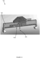
- FIG. 1 illustrates an example metrology bridge 100, according to various embodiments.
- the metrology bridge 100 may couple to a measurement assembly and may be utilized for measurement of an object, or some portion thereof.
- the metrology bridge 100 may include a housing 102.
- the housing 102 may comprise a rigid structure.
- the housing 102 may comprise a semi-flexible structure, a rigid structure, or some combination thereof.
- the housing 102 may be formed of aluminum, steel, stainless steel, ceramic, carbon fiber, plastic, or some combination thereof.
- the housing 102 may be elongated in one or more directions.
- the housing 102 may include a plurality of sidewalls with a cavity enclosed by the sidewalls. In other embodiments, one or more of the sidewalls may be omitted, such as to provide easy access to the cavity.
- the metrology bridge 100 may further include one or more sensor devices located within the cavity of the housing 102.
- the sensor devices, or some portion thereof, may extend out of the cavity.
- the sensor devices may comprise contactless sensor devices.
- the utilization of contactless sensor devices along with taking measurements while a sensor device is in motion relative to the object being measured may allow for increased inspection speed of the object due to the lack of contact with the object and lack of requirement that the sensor and object be still relative to each other. Further, there exists less risk of damage to or defects induced within the object based on the lack of contact.
- the sensor devices may comprise sensor devices utilize contact for measurement, contactless sensor devices, or some combination thereof.
- Each of the sensor devices may have one or more sensor elements, such as the sensor elements 104.
- the sensor elements 104 may include a lens of a camera, a lens of a laser, an extension member of confocal sensor device, a probe of a sensor device, or some combination thereof.
- the sensor elements 104 may be located at a first side 106 of the housing 102 and/or may be directed out of the housing 102.
- the sensor elements 104 may be directed along a plane that extends substantially from the first side 106 of the housing 102.
- the sensor elements 104 may share a common focal plane at a predetermined distance from the housing 102.
- the sensor elements 104 sharing a common focal plane may allow for simultaneous capturing of information by multiple sensor devices, allowing for increased inspection speed.
- one or more sensor elements 104 may be configured to move within housing 102, such as via rotation or limited translation.
- additional axes of motion or freedom e.g. seven, eight, or more axes may be enabled, combined with movements from metrology bridge 100 and the object, as will be described below with respect to at least Figs. 2A-2D .
- the use of multiple sensor elements 104 may allow for simultaneous capture of multiple measurements at a single point in time, thereby potentially improving measurement throughput.
- the multiple sensor elements 104 may be of an identical type, e.g. measuring tolerances or distances, so that multiple tolerances and/or dimensions of an object to be measured can be captured relatively simultaneously.
- the multiple sensor elements 104 may be of different types, so that multiple types of measurement data of an object can be captured relatively simultaneously.
- a sensor device may have multiple sensor elements 104, with each sensor element 104 oriented in a different fashion, to allow a single sensor device to potentially make multiple measurements in different directions or dimensions substantially simultaneously.
- a single laser sensor may be equipped with two sensor elements 104 that are positioned orthogonally, so that measurements can be made simultaneously in downward and lateral directions.
- Such a configuration may be useful for inspecting a bore, where a depth of the bore can be measured concurrently with a radius or thread feature of the bore that is positioned radially.
- metrology bridge 100 may include one or more non-sensing tools as part of sensor elements 104.
- these tools may be considered sensor elements 104 due to their mounting in a common fashion.
- the non-sensing tools may allow for manipulation of the object to be measured in various ways, e.g. hole creation with a drill or boring tool, hole or gap filling via a filling tool (such as with an epoxy or other suitable resin or adhesive), a machining head, object manipulation to rotate or flip the object to allow other aspects of the object to be measured, etc.
- the housing 102 may include a removable mounting plate 118 mounted at the first side 106 of the housing 102.
- the sensor devices may be mounted to the removable mounting plate 118.
- the removable mounting plate 118 may be removed from the housing 102 and may be replaced by a different removable mounting plate 118 having different sensor devices.
- mounting plate 118 is configured to be moveable with respect to the housing 102, to enable sensor elements 104 to translate along the length of metrology bridge 100. This movement allows sensor elements 104 to be repositioned to accommodate the measurement of objects that, due to a relatively large size, limit the possible range of motion of the stage and platen.
- sensor elements 104 may have a first position in approximately the center of housing 102, as depicted in Fig. 1 , and a second position proximate to first counterbalance 116a (such as around the location of the arrow for first side 106). In other embodiments, sensor elements 104 may have one or more additional third, fourth, fifth, etc.
- sensor elements 104 may lock into a kinematic stop, which securely and repeatably locks the sensor elements 104 into a precise location with minimal or no position error. In such embodiments, sensor elements 104 may translate between such kinematic stops with a relatively simple mechanism that need not be calibrated to high precision.
- metrology bridge 100 may be equipped with a high precision movement or mechanism for sensor elements 104, in addition to or in lieu of discrete kinematic stops.
- a mechanism may allow a virtually infinite number of positions for sensor elements 104 to be repeatably and accurately obtained without the need for one or more kinematic stops.
- Such a mechanism to achieve repeatable accuracy to potentially a micron level, may need to account for factors such as gravity sag (particularly if metrology bridge 100 spans a relatively great distance, temperature fluctuations (where system 200 is not contained within a controlled micro-environment), vibration, etc.
- the housing 102 may include a removable panel 120 in some embodiments.
- the removable panel 120 may be located at a second side 122 of the housing 102, where the second side 122 may be located opposite to the first side 106.
- the removable panel 120 may be removed from the housing 102 allowing access to the sensor devices within the housing 102. Further, the removable panel 120 may be removed to provide for wire routing and/or space for sensor devices that may require additional space.
- the metrology bridge 100 may further include one or more mounting members 108.
- the metrology bridge 100 includes a first mounting member 108a and a second mounting member 108b in the illustrated embodiment.
- the first mounting member 108a may be located at a first end 110 of the housing 102 and the second mounting member 108b may be located at a second end 112 of the housing 102, where the second end 112 is opposite from the first end 110.
- the mounting members 108 may rotatably couple the housing 102 to the measurement assembly.
- each of the mounting members 108 may include apertures, such as apertures 114, that engage with the measurement assembly.
- the metrology bridge 100 may rotate about the apertures 114.
- the metrology bridge 100 may further include one or more counterbalances 116.
- the counterbalances 116 may be coupled to the mounting members 108 and may counterbalance the housing 102 about the mounting members 108.
- the metrology bridge 100 may include a first counterbalance 116a and a second counterbalance 116b in the illustrated embodiment.
- the first counterbalance 116a may be coupled to the first mounting member 108a and the second counterbalance 116b may be coupled to the second mounting member 108b.
- the first counterbalance 116a may be coupled to an opposite side of the first mounting member 108a from the housing 102, and the second counterbalance 116b may be coupled to the opposite side of the second mounting member 108b from the housing 102.
- the counterbalances 116 may be selected to be a weight substantially equal to the combined weight of the housing 102 and the sensor devices. For example, the counterbalances 116 may be selected to require a minimum amount of force to rotate the metrology bridge 206.
- counterbalances 116 may be formed of aluminum, steel, stainless steel, or some combination thereof.
- the counterbalances 116 may be interchangeable in some embodiments.
- the counterbalances 116 may be detachable from the mounting members 108 and may be replaced by counterbalances 116 of different weights, materials, and/or shapes.
- the mounting members 108 with the counterbalances 116 may be detachable from the housing 102 and may be replaced by mounting members 108 with counterbalances 116 of different weights, materials, and/or shapes.
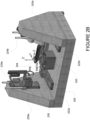
- FIGS 2A and 2B illustrate an example metrology system 200, according to various embodiments.
- the metrology system 200 may include a body 201.
- the metrology system 200 may further include a platen 204, that sits upon a stage 203, which in turn sits upon a base 202, where base 202 is part of body 201.
- the platen 204 may be located at a side of the body 201.
- the platen 204 may receive an object to be measured.
- the metrology system 200 may further include a metrology bridge 206.
- the metrology bridge 206 may include one or more of the features of the metrology bridge 100 ( Fig. 1 ).
- the metrology bridge 206 may be rotatably coupled to the body 201 of the measurement assembly by one or more mounting members, such as the mounting members 108 ( Fig. 1 ).
- Sensor elements of sensor devices located within the metrology bridge 206 may be directed toward the platen 204.
- the sensor elements may be directed along a plane that intersects the platen 204 and/or may have a common focal plane directed at the platen 204.
- metrology system 200 may include multiple metrology bridges 206, that may be configured for independent movement.
- each metrology bridge 206 may be independently moveable in both a Z and a phi axis, to be discussed in more detail below.
- the bridges may each have identical or different sensor packages, depending upon the needs of a given embodiment. Identical sensor packages may allow simultaneous measurement of different portions of an object with a common type of measurement, to potentially improve throughput. Different sensor packages may allow simultaneous measurement of different aspects of the object, e.g. depth and surface texture or finish, etc.
- the metrology system 200 may further include a motor 208.
- the motor 208 may be affixed to the body 201 of the metrology system 200.
- the motor 208 may act upon the metrology bridge 206 and cause the metrology bridge 206 to rotate about an axis of rotation 210.
- the axis of rotation 210 may be coincident with a focal plane and/or a focal line of the sensor elements of the sensor devices within the metrology bridge 206.
- the sensor elements may be directed toward the axis of rotation 210.
- the motor 208 being affixed to the body 201 may provide for smoother rotation of the metrology bridge 206 and can provide for better accuracy of positioning of the metrology bridge 206.
- Base 202 comprises a part of body 201.
- base 202 may be constructed of a relatively massive/heavy material, such as stone.
- the stone is granite, which can provide a relatively temperature insensitive, vibration resistant, and precisely dimensioned base from which to make measurements.
- a stable base 202 is crucial, and can serve as a calibration or reference datum from which the sensors in metrology bridge 206 can calibrate.
- base 202 may be equipped with specific features configured to act as calibration targets; by permanent affixation to base 202, these targets present highly precise known reference points with which metrology system 200 may calibrate the various sensor elements 104 in metrology bridge 206.
- System 200 may, in embodiments, be configured to self-calibrate on an as-commanded or routine basis.
- Base 202, or another part of system 200 may be configured with one or more calibration targets or mechanisms to allow self-calibration.
- system 200 may be configured to perform a self-check/self-calibration during inspection and measurement of an object, to ensure that acceptable accuracy is maintained.
- base 202 may further employ passive and/or active vibration cancellation techniques, to optimize measurement precision.
- vibration damping assemblies e.g. vibration isolating assemblies, supports
- one or more motion sensors may be equipped to body 201, metrology bridge 206 and/or base 202 to detect vibrations transmitted through the metrology system 200, and employ anti-vibration mechanism(s) (such as a counterweight or mass damper), factor the vibration movements into the measurement errors, or a combination of both techniques or possibly other techniques to suppress vibration-induced measurement errors.
- anti-vibration mechanism(s) such as a counterweight or mass damper
- Metrology system 200 in the depicted embodiment, includes a kinematic stage 203, upon which platen 204 is disposed. Stage 203 itself may rest upon base 202. In embodiments, stage 203 is configured to move relative to base 202, and thereby move platen 204, and any object secured to platen 204. Where stage 203 is configured to move, an object on platen 204 may be measured both either sensors in metrology bridge 206 being moved around the object, by the object itself being moved relative to the sensors in metrology bridge 206 (by virtue of stage 203 moving relative to base 202), or a combination of both.
- Stage 203 may move relative to base 202 on one or more bearings, such as fluid bearings, discussed below.
- the bearings if implemented as a fluid bearing, may be powered by pressurized air supply delivered to stage 203 or, in some embodiments, to at least a portion of base 202, or both.
- the use of air or other types of fluid bearings allows stage 203 to move across base 202 in a relative frictionless fashion, which allows measurement precision to be maintained where friction and other mechanical phenomena may otherwise act to diminish the precision by which stage 203 may be placed relative to base 202 and the sensors in metrology bridge 206. Maintaining this precision also enables stage 203 in conjunction with or alternatively to base 202 to be used as a reference datum for sensor calibration and measurement.
- Stage 203 itself may be manufactured from a similarly heavy/dense material as base 202.
- system 200 may be equipped with multiple stages 203, to accommodate measurement of multiple objects, potentially simultaneously.
- system 200 may be equipped to accept multiple objects on a single stage 203, and possibly upon a single platen 204.
- system 200 may be configured, via software or other control logic, to measure each object in turn automatically.
- a system 200 so configured may be able to measure each object simultaneously, such as where system 200 is equipped with multiple metrology bridges 206 and/or multiple sensor devices (including multiple sensor elements) in a single metrology bridge 206.
- each object of the multiple objects may be measured in a different coordinate system, as will be discussed below.
- the bearings supporting stage 203 may be independent for one or more axes.
- stage 203 may be capable of translation movement in both an x and y axis, e.g. across the surface of base 202, rather than stage 203 resting upon a single axis rail (e.g. x only), which in turn supports a second axis rail (e.g. y only).
- a single axis rail e.g. x only
- second axis rail e.g. y only
- a movement for the y axis rests upon a rail or bearing that only moves in the x axis (similar to the depiction of Fig. 2A )
- any error in x axis positioning automatically is passed to they axis, which itself may introduce its own error.
- any position of an object moved by stage 203 with stacked movements results in a cumulative error from across all stacked axes.
- Fig. 2C This arrangement is diagrammatically depicted in Fig. 2C .
- base 202 supports an X-stage 240, which in turn supports a Y-stage 242, which in turn supports a Z- (and possibly theta, depending upon the configuration of a given system 200) stage 244.
- X-stage 240 may introduce a positional error 241 relative to base 202.
- Y-stage 242 may introduce a positional error 243 relative to X-stage 240
- Z-stage 244 may introduce a positional error 245 relative to Y-stage 242.
- the positional errors combine additively to result in an overall error that may be larger than acceptable tolerances. Such errors may be minimized, but potentially at great cost to achieve an error within acceptable tolerances.
- each of X-stage 240, Y-stage 242 and/or Z-stage 244 is directly moved relative to base 202, and as such, the positional error 260 of each stage is independent, and does not stack.
- the overall error in contrast to the additive error of the configuration of Figs. 2A and 2C , is simply the error 260 presented by any given single stage, without influence from the positional errors of the other stages.
- Fig. 2B depicts an alternative embodiment for system 200 that incorporates independent stages.
- the embodiment of Fig. 2B includes the base 202 of Fig. 2A , which may be made from granite or another suitably massive and relatively stable material.
- stage 203 Upon base 202 rests stage 203, upon which is platen 204.
- stage 203 is coupled to an X-stage 226 that is independent from Y-stage 222a and Y'-stage 222b.
- the Y-stage is split between Y and Y', which move in synchronization to provide adequate precision of movement of stage 203 in the Y axis.
- stage 203 which supports an object to be measured and references the X and Y plane established by base 202 via stage 203, may also move in a theta axis (rotation).
- the theta axis movement in embodiments, is supplied by stage 203, such as via a motor (pneumatic, hydraulic, electric, or another suitable mechanism), and is further referenced to base 202 via stage 203.
- stage 203 itself may be configured to rotate along the theta axis directly against base 202.
- stage 203 may allow platen 204 to be fixed in position relative to stage 203, such as to reduce possible positional error and/or to simplify construction of stage 203 and platen 204.
- Fig. 2B shows the gantry for X-stage 226 moving atop Y and Y'-stages 222a and 222b to permit stage 203 to be coupled for movement via a single mechanical connection
- other embodiments may place the X-stage 226 directly atop base 202, with X and Y stages mechanically coupled separately to stage 203.
- FIG. 2B Also visible in Fig. 2B are two upright portions 220a and 220b of base 202.
- the upright portions 220a and 220b may be integral with base 202 and/or constructed from a similar or identical material. Upright portions 220a and 220b support metrology bridge 100 in a stable fashion. While two upright portions 220a and 220b are depicted, other embodiments may have none, one, or more upright portions.
- the upright portions 220a and 220b may be substantially identical in configuration (as shown), or may differ in configuration from each other, as the needs of a given implementation require. Upright portions 220a and 220b may be manufactured from identical or different materials.
- upright portions 220a and 220b are formed as part of base 202 (e.g. integral). In other embodiments, upright portions 220a and 220b are constructed as separate structures, and subsequently joined or disposed upon base 202. In either construction, base 202 is intended to include any upright portions 220a, 220b (or more), as upright portions 220a and 220b effectively act as extensions of base 202 to provide a solid support for any equipment, such as metrology bridge 100 and corresponding motion equipment.
- Metrology bridge 100 in the depicted embodiment, is moved in an independent Z-axis via Z-stage 224a and Z'-stage 224b.
- Z-stages 224a and 224b as with Y-stages 222a and 222b, move in a synchronized fashion, and act to raise or lower metrology bridge 100 along the Z axis indicated in Fig. 2B .
- the Z stage moves independently and directly relative to base 202 (including upright portions 220a and 220b).
- Fig. 2B depicts additional axes theta (rotation of platen 204) and phi (rotation of metrology bridge 100), to provide at least five degrees of movement.
- platen 204 may be configured to move in a theta (rotational) axis, noted in Fig. 2B . Some such embodiments may provide such rotation relative to stage 203. Other embodiments may provide such rotation relative to base 202 as a third independent axis for stage 203. In such embodiments, platen 204 may be fixed relative to stage 203 (or may simply be integrated into stage 203), with rotation provided through stage 203.
- System 200 may use other coordinate/positioning systems to express degrees of movement, such as R-Theta, where position is expressed in terms of object rotation and radius, along with an ascension/declination axis, which may be appropriate for substantially spherical objects.
- R-Theta where position is expressed in terms of object rotation and radius, along with an ascension/declination axis, which may be appropriate for substantially spherical objects.
- An R-H or R-Z system may be appropriate for substantially cylindrical objects, with position expressed in terms of radial distance and height, and further with a rotational component.
- Other coordinate systems may be appropriate, e.g. polar, depending upon the nature of a measured object.
- system 200 may be configured (such as by controlling software) to translate between inputs in one coordinate system and the coordinate system native to system 200.
- system 200 may be configured to accept positions for measurement expressed in an R-Theta system and translate those positions into X, Y, and Z (plus theta, phi, etc), if system 200 is configured with a Cartesian system.
- stage 203 can facilitate such independent axis movements.
- the metrology bridge 206 is rotated and moved (and thus, the sensor elements on the bridge 206) separately from the stage 203 and platen 204, allowing z and Phi (rotation of the metrology bridge 206) axes to remain independent.
- Employing a stage 203 with independent x and y axes, and (in embodiments) an independent theta axis further allows positional errors to be limited only to a single axis error, with no accumulation of errors.
- stage 203 may employ different types of bearings, such as fluid (of which an air bearing may be considered a type), e.g. hydraulic, mechanical bearings (such as journals, ball bearings, needle bearings, race bearings, etc), electromagnetic, or any other suitable type of bearing that can support the weight of an object being measured and allow relatively frictionless and easy movement of stage 203.
- fluid of which an air bearing may be considered a type
- mechanical bearings such as journals, ball bearings, needle bearings, race bearings, etc
- electromagnetic or any other suitable type of bearing that can support the weight of an object being measured and allow relatively frictionless and easy movement of stage 203.
- platen 204 may be somewhat simplified by obviating the need to means to securely hold the object to be measured. Instead, a simple clamp or pin, or a universal base equipped to quickly receive and release object shape-specific holders may be employed to allow for rapid changing of objects to be measured. Such rapid changing can allow metrology system 200 to be rapidly switched between different objects without loss of productivity relative to conventional known metrology systems.
- the metrology system 200 may include a plurality of metrology bridges, such as the metrology bridge 206, in other embodiments.
- each of the metrology bridges may be coupled to the body 201 at the same point and each may rotate about the axis of rotation 210 (e.g., a phi axis).
- the metrology bridges may be coupled to the body 201 at different locations and may rotate about different axes of rotation.
- metrology system 200 may be equipped to a mechanism to allow an object to be measured to be automatically loaded or unloaded from platen 204.
- metrology bridge 100 may be equipped with sensor elements 104 that are capable of manipulating an object; such sensor elements 104 could be configured to place an object upon platen 204, possibly in conjunction with movements from stage 203.
- sensor elements 104 include visual scanners (e.g. optical cameras or sensors that can detect an object shape)
- metrology apparatus 200 may be configured to allow placement of an object on platen 204 in any arbitrary position, with a camera or other suitable sensor being used to detect the orientation and location of the object and adjust the object inspection plan accordingly.
- metrology bridge 100 may act to reposition the object, based upon its detected position, to a desired position for use with the object inspection plan.
- the camera or other sensor may be used to detect the type of object, and, via object recognition techniques (such as those known in the art) load the appropriate object inspection plan for an effectively automatic measurement process.
- metrology system 200 may include or be located within an enclosure for micro-environmental control of various factors such as temperature, humidity, air pressure, ensuring zero air movements, etc., for applications where the precision of measurement of objects may be critically affected by environmental factors. Further still, metrology system 200 may include operational software that can run upon one or more control units or devices that drive and/or coordinate operations of the various system on metrology apparatus 200, such as the actuators to move stage 203 (and by extension, platen 204), rotate platen 204, as well as one or more motors 208 that may be connected to and drive metrology bridge 206 or some component thereof. Further, the software may coordinate triggering and receiving measurements from one or more sensors that may be equipped to metrology bridge 206.
- the software can automate collection of a point cloud of measurements for any object to be measured.
- the software itself may run on a microcontroller, PC, dedicated hardware, or some combination of the foregoing; moreover, the software may be implemented in whole or in part in the form of firmware or, in some embodiments, hardware, such as a custom-designed application specific integrated circuit (ASIC), field-programmable gate array (FPGA), or some other suitable device or combination of devices and/or software.
- ASIC application specific integrated circuit
- FPGA field-programmable gate array
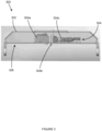
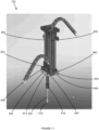
- FIG 3 illustrates a side view of an example metrology bridge 300, according to various embodiments.
- the metrology bridge 300 may include one or more of the features of the metrology bridge 100 ( Fig. 1 ).
- the metrology bridge 300 may include a housing 302, which may include one or more of the features of the housing 102 ( Fig. 1 ) including a cavity 304.
- the metrology bridge 300 may include a plurality of sensor devices 304 located within the cavity 304.
- the metrology bridge 300 includes a first sensor device 304a, a second sensor device 304b, and a third sensor device 304c located within the cavity 304 in the illustrated embodiment.
- the first sensor device 304a is a laser device
- the second sensor device 304b is a confocal sensor device
- the third sensor device 304c is a camera device in the illustrated embodiment.
- the plurality of sensor devices 304 may include point lasers, line scan lasers, direct light modeling lasers, white light sensors, interferometers, video sensors, camera sensors, confocal sensors, color sensors, adhesion sensors, humidity sensors, temperature sensors, surface finish sensors, capacitance sensors, touch probe sensors, air gauge sensors, ultrasonic sensors, x-ray sensors, imaging sensors, deep learning sensors, white light interferometry sensors, chromatic confocal sensors, stereo line scan sensors, laser triangulation sensors, white light confocal sensors, vision sensors, infrared sensors, X-ray sensors, other sensors appropriate to a given implementation, or some combination thereof.
- the plurality of sensor devices 304 may be mounted to the housing 302 at a side 306 of the housing 302.
- the sensor devices 304 may be selected with respect to, and/or may impact, the types of measurements and/or other inspections that metrology system 200 can perform.
- employing a sensor device 304 that includes a contactless sensor that can read measurements laterally e.g. may be able to measure orthogonally from a longitudinal axis of the sensor
- a bore or (possibly) threaded hole can be inspected using such a sensor configuration, as the sensor device 304 can insert into the bore and measure thread and/or other bore features by sensing laterally.
- sensor device 304 may be capable of extension and retraction independent from any Z-axis movement of the metrology bridge 300, and may further be capable of independent rotation, separate from any theta-axis movement of platen 204/stage 203.
- FIG 4 illustrates a perspective view of the example metrology bridge 300 of Figure 3 , according to various embodiments.
- the metrology bridge 300 may include a removable mounting plate 402 located at the side 306 of the housing 302.
- the sensor devices 304 may be mounted to the removable mounting plate 402. Further, the removable mounting plate 402 may have a plurality of openings 404 for sensor elements 406 of the sensor devices 304.
- the removable mounting plate 402 has a first opening 404a that corresponds to a laser lens 406a of the first sensor device 304a, a second opening 404b that corresponds to a displacement member 406b of the second sensor device 304b, and a third opening 404c that corresponds to a camera lens 406c of the third sensor device 304c in the illustrated embodiment.
- the removable mounting plate 402 may be removed from the housing 302 and replaced by another removable mounting plate.
- the other removable mounting plate may have different sensor devices mounted to the removable mounting plate. Further, the other removable mounting plate may have different openings for the sensor elements of the different sensor devices.
- Sensor elements, such as the sensor elements 406, may comprise laser lens, displacement members, camera lens, speakers, humidity sensor receptors, probes, or some combination thereof.
- the sensor elements 406 of the sensor devices 304 may be directed in a same direction. Further, the sensor elements 406 may be aligned in a linear fashion along a length of the housing 302. For example, the sensor elements 406 may be directed along a plane that extends substantially (within 5 degrees) perpendicular from the side 306 of the housing 302. Further, sensor elements 406 may share a common focal plane in some embodiments.
- the openings 404 may further be aligned in a linear fashion along the length of the housing 302.
- FIG 5 illustrates an example sensor device arrangement 500, according to various embodiments.
- the sensor device arrangement 500 may be implemented within a metrology bridge, such as the metrology bridge 100 ( Fig. 1 ), the metrology bridge 206 ( Fig. 2A ), and/or the metrology bridge 300 ( Fig. 3 ).
- the sensor device arrangement 500 may include a plurality of sensor devices 502.
- the sensor device arrangement 500 includes a first sensor device 502a, a second sensor device 502b, and a third sensor device 502c.
- the sensor device arrangement 500 may include two or more sensor devices 502.
- Each of the sensor devices 502 may include a sensor element 504.
- the sensor element 504 may comprise a portion of the sensor device 502 at which external data for the sensor device 502 is collected.
- the sensor element 504 for a laser sensor device comprises a laser lens through which the laser is emitted and data is collected
- the sensor element 504 for a confocal sensor device comprises an extension member (discussed in greater detail below) that extends from the confocal sensor device and collects data
- a camera lens through which an image is captured.
- the sensor elements 504 may be aligned along a length of a housing in which the sensor devices 502 are located.
- the laser lens 504a of the first sensor device 502a, the extension member 504b of the second sensor device 502b, and the camera lens 504c of the third sensor device 502c are aligned along the length of the housing, as indicated by line 506.
- FIG. 6 illustrates an example sensor device arrangement 600, according to various embodiments.
- the sensor device arrangement 600 may be implemented within a metrology bridge, such as the metrology bridge 100 ( Fig. 1 ), the metrology bridge 206 ( Fig. 2A ), and/or the metrology bridge 300 ( Fig. 3 ).
- the sensor device arrangement 600 may include a plurality of sensor devices 602.
- the sensor device arrangement 600 includes a first sensor device 602a, a second sensor device 602b, and a third sensor device 602c.
- the first sensor device 602a, the second sensor device 602b, and the third sensor device 602c may be the same sensor devices as the first sensor device 502a ( Fig. 5 ), the second sensor device 502b ( Fig. 5 ), and the third sensor device 502c ( Fig. 5 ), respectively.
- the first sensor device 602a of the sensor device arrangement 600 may be mounted in a different direction than the first sensor device 502a of the sensor device arrangement 500 ( Fig. 5 ).
- the first sensor device 602a may be mounted in an orientation that is 90 degrees different from the orientation of the first sensor 502a.
- Each of the sensor devices 602 may include a sensor element 604.
- the sensor elements 604 may be aligned along a length of a housing in which the sensor devices 602 are located.
- the laser lens 604a of the first sensor device 602a, the extension member 604b of the second sensor device 602b, and the camera lens 604c of the third sensor device 602c are aligned along the length of the housing, as indicated by line 606.
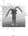
- FIG. 7 illustrates an example metrology bridge 700 with a sensor assembly 702, according to various embodiments.
- the metrology bridge 700 may include one or more of the features of the metrology bridge 100 ( Fig. 1 ), the metrology bridge 206 ( Fig. 2A ), and/or the metrology bridge 300 ( Fig. 3 ).
- the sensor assembly 702 includes two sensor devices. In other embodiments, the sensor assembly 702 may include one or more sensor devices. While the depicted embodiment of Figs. 7-11 is a confocal sensor, it should be understood that this is for example only.
- Sensor assembly 702 may be any suitable sensor type that can benefit from the movements and kinematic positioning described below. Sensor assembly 702 may include zero, one, or more confocal sensors.
- the sensor assembly 702 may be located partially within a cavity 704 of a housing 706 of the metrology bridge 700.
- the metrology bridge 700 may include an add-on housing 708 that couples to the housing 706 and houses the portion of the sensor assembly 702 that extends out of the cavity 704.
- a removable panel such as the removable panel 120 ( Fig. 1 )
- the add-on housing 708 may be coupled to the housing 706 in place of the removable panel.
- FIG 8 illustrates the example sensor assembly 702 of Figure 7 , according to various embodiments.
- the sensor assembly 702 may include a guide 802.
- the guide 802 may support one or more sensor devices (of the same or a different type) and provide structure for guiding portions of the sensor devices as the portions are extended and retracted.
- the guide 802 includes a first rod 804 and a second rod 808 in the illustrated embodiment.
- the first rod 804 and the second rod 808 may extend from a first end 810 of the guide 802 to a second end 812 of the guide 802.
- the guide 802 may couple to a housing (such as the housing 706 ( Fig. 7 )) for mounting the sensor devices within the housing.
- the portions are extended/retracted with a drive mechanism such as a pneumatic cylinder 806.
- a drive mechanism such as a pneumatic cylinder 806.
- the illustrated embodiment uses a pneumatic cylinder
- other embodiments may drive cylinder 806 by other means, such as electric, hydraulic, or another suitable source of power.
- Still other embodiments may drive the various portions using an alternative mechanism to cylinder 806, e.g. a geared or belted drive, jack screw, or another suitable mechanism that can drive the portions with a suitable accuracy and control.
- the guide 802 may include a kinematic positioning element 814.
- the kinematic positioning element 814 may be located at the second end 812 of the guide 802.
- Kinematic position element 814 couples with a kinematic frame 826 (such as by first rod 804 and second rod 808) to form a kinematic mount that carries one or more sensor devices 816a and 816b, to be discussed in greater detail below.
- the kinematic positioning element 814 is translated along the first rod 804 and/or the second rod 808 via motion from cylinder 806.
- the kinematic positioning element 814 may facilitate kinematic positioning of extension members of the sensor devices, as described further throughout this disclosure.
- the kinematic positioning element 814 may include three contact points to facilitate kinematic positioning of an extension member.
- the kinematic positioning element 814 may include a first recess 832, a second recess 834, and a contact point 836 to facilitate kinematic positioning in the illustrated embodiment.
- Other embodiments may have a third recess (not shown), or more or fewer recesses depending upon the needs of a given implementation.
- the sensor assembly 702 may include one or more sensor devices 816a and 816b (816b is depicted by to dashed circles, but is not otherwise visible), collectively referred to as 816.
- the sensor assembly 702 includes a first sensor device 816a and a second sensor device 816b; other embodiments may only have a single sensor device 816, or may have more than two sensor devices 816.
- features related to the first sensor device 816a are described herein. It is to be understood that the second sensor device 816b (and any other additional such devices) may include one or more of the features of the first sensor device 816a.
- the first sensor device 816a may include an extension member comprised of an extension housing 818 and extension 820.
- Extension 820 may further comprise a sensor element 822 of the first sensor device 816a, which includes components for making the actual measurements.
- the extension housing 818, along with extension 820 and sensor element 822 as attached, may be extended and retracted during operation of the first sensor device 816a.
- this extension and retraction may provide an additional degree of motion independent from the Z-axis of the metrology bridge, such as where metrology bridge is rotated relative to base 202 so that sensor element 822 extends substantially parallel to base 202.
- This extension and retraction may be between one or more defined kinematic stops, or may be substantially continuous, in embodiments where sensor element 822 can be repeatably positioned with acceptably high accuracy.
- the first sensor device 816a may include an actuator that can cause the extension 820 and/or extension housing 818 to rotate while the sensor element 822 remains static, thus enabling an additional degree of motion.
- the first sensor device 816a may, in some embodiments, include one or more sensor elements (such as camera lens and/or laser lens) located along the extension housing 818.
- the first sensor device 816a may include an additional capture element located along the extension 820 of the extension housing 818 (in addition or alternative to sensor element 822), as described further throughout this disclosure.
- the first sensor device 816a may further include a displacement member 824.
- the displacement member 824 may be coupled to the first rod 804 and/or the second rod 808, and may be translated along the first rod 804 and/or the second rod 808.
- the displacement member 824 may include one or more apertures through which the first rod 804 and/or the second rod 808 extend.
- the displacement member 824 may slide along the lengths of the first rod 804 and/or the second rod 808 as translated.
- the displacement member 824 is coupled to the first rod 804 and the second rod 808 and is translated along the first rod 804 and the second rod 808 in the illustrated embodiment.
- the displacement member 824 may further include a kinematic frame 826.
- the extension housing 818 may be coupled to the kinematic frame 826, the displacement member 824, or some combination thereof.
- the kinematic frame 826 may engage with the kinematic positioning element 814 to position the extension housing 818.
- the kinematic frame 826 may include three contact elements to contact the kinematic positioning element 814 when engaged to position the extension housing 818.
- the kinematic frame 826 may include a first contact element 838, a second contact element 840, and a third contact element 842 that are to contact the kinematic positioning element 814 in the illustrated embodiment.
- the first contact element 838 may contact the seat within the first recess 832
- the second contact element 840 may contact the contact point 836
- the third contact element 842 may seat within the second recess 834, as described further throughout this disclosure.
- the first sensor device 816a may include an actuation mechanism 828.
- the actuation mechanism 828 may be coupled to the displacement member 824. Further, the actuation mechanism 828 may engage with the first rod 804 and/or the second rod 808, and may translate the displacement member 824 along the first rod 804 and/or the second rod 808. The translation of the displacement member 824 may cause the extension housing 818 to be extended or retracted. The displacement member 824 may decouple from the kinematic frame 826 when the extension housing 818 is in an extended position, as described further throughout this disclosure.
- the first sensor device 816a may further include a cable protector element 830.
- the cable protector element 830 is a chain-style cable protector in the illustrated embodiment.
- the cable protector element 830 may comprise a chain-style cable protector, a tube-style cable protector, a spiral-type cable protector, braided sleeving, fabric sleeving, heat shrink, grommets, or some combination thereof.
- the cable protector element 830 may be coupled to the displacement member 824 and encompass cables and/or wires of the first confocal sensor device 816a, thereby protecting the cables and/or wires from damage.
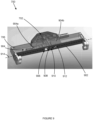
- FIG 9 illustrates a perspective view of the example metrology bridge 700 of Figure 7 , according to various embodiments.
- the metrology bridge 700 may further include a removable mounting plate 902.
- the removable mounting plate 902 may include one or more of the features of the removable mounting plate 118 ( Fig. 1 ) and/or the removable mounting plate 402 ( Fig. 4 ).
- the sensor assembly 702 may be mounted to the removable mounting plate 902.
- the kinematic positioning element 814 ( Fig. 8 ) and/or the guide 802 ( Fig. 8 ) may be mounted to the removable mounting plate 902.
- One or more other sensor devices 904 may also be mounted to the removable mounting plate 902.
- the sensor devices 904 may include one or more of the features of the sensor devices 304 ( Fig.
- the sensor devices 904 may be omitted.
- the mounting plate 902 (or a similar structure) may be configured to move in some embodiments, to allow repositioning of sensor assembly 702 and/or sensor devices 904.
- the removable mounting plate 902 may have a plurality of openings for the sensor assembly 702 and/or the sensor devices 904.
- the removable mounting plate 902 may have openings for the extension members of the sensor devices 816 ( Fig. 8 ) and/or sensor elements of the sensor devices 904.
- the removable mounting plate 902 has a first opening 906 corresponding to a sensor element of a first sensor device 904a, a second opening 908 corresponding to a first sensor device 816a ( Fig. 8 ), a third opening 910 corresponding to an extension member of a second sensor device 816b, and a fourth opening 912 corresponding to a sensor element of a second sensor device 904b.
- the sensor element of the first sensor device 904a, the extension housing 818, the extension member of the second sensor device 816b, and the sensor element of the second sensor device 904b may be aligned along a length of the housing 706, as indicated by line 914, and may be directed out of the housing 706.
- Figure 10 illustrates the example metrology bridge 700 of Figure 7 with a sensor device 816 ( Fig. 8 ) in an extended position, according to various embodiments.
- the sensor device 816 may extended out of the housing 706 through the second opening 908 ( Fig. 9 ) of the removable mounting plate 902 ( Fig. 9 ).
- the sensor device 816 may extend along a plane that extends from the second opening 908 substantially (within 5 degrees) perpendicularly from a side 1002 of the housing 706.
- Figure 11 illustrates the example sensor assembly 702 of Figure 7 with an extension housing 818 and associated extension 820 in the extended position, according to various embodiments.
- the extension housing 818 may have been translated to the extended position by the actuation mechanism 808.
- the actuation mechanism 808 may have been translated by the displacement member 824 along the first rod 804 and the second rod 808 to cause the extension housing 818 (and by connection, the sensor tip) to translate to the extended position.
- the actuation member 828 may be decoupled from the displacement member 824 when the extension housing 818 is located in the extended position.
- the actuation member 828 may include an electromagnet, a physical element, or combination thereof that couples the actuation member 828 to the displacement member 824.
- the electromagnet, the physical element, or combination thereof may decouple the actuation member 828 from the displacement member 824 when the extension housing 818 is in the extended position.
- the electromagnet, the physical element, or combination thereof may recouple the actuation member 828 to the displacement member 824 to move the extension housing 818 out of the extended position.
- the kinematic frame 826 may engage the kinematic positioning element 814.
- the kinematic frame 826 may seated at three points of the kinematic positioning element 814 when the kinematic frame 826 is engaged with the kinematic positioning element 814.
- the first contact element 838 is seated within the first recess 832 ( Fig. 8 )
- the second contact element 840 contacts the contact point 836 ( Fig. 8 )
- the third contact element 842 is seated within the second recess 834 in the illustrated embodiment.
- the kinematic frame 826 being seated at the three points of the kinematic positioning element 814 may facilitate positioning of the extension housing 818, and may improve repeatability and precision in positioning of the extension housing 818.
- the sensor assembly 702 may further include one or more sensor devices to determine whether the kinematic frame 826 had been moved from proper engagement with the kinematic positioning element 814 and/or did not achieve proper engagement with the kinematic positioning element 814. For example, the sensor devices may determine whether the first contact element 838 is properly seated within the first recess 832, the second contact element 840 contacts the contact point 836, and/or the third contact element 842 is properly seated within the second recess 834.
- kinematic frame 826 and kinematic position element 814 help ensure a repeatable registration into a locked position for accurate measurements.
- some slop, movement, or other error may be permitted.
- the system 200 may be triggered to slow or stop movement of the various components (e.g. stage 203 with an object to be measured, metrology bridge 206, associated sensor devices, etc.) to prevent damage to system 200, its various components, and or the object being measured, due to undesirable contact between the object being measured and a part of system 200 (a/k/a a "crash").
- the extension housing 818 may further include a capture element 1102 located along a side of the extension housing 818.
- the capture element 1102 may comprise a laser lens, camera lens, interferometer, or some combination thereof.
- the capture element 1102 may directed outwards from the extension housing 818.
- the capture element 1102 may be directed in a different direction than the direction of extension and retraction of the extension housing 818.
- the extension 820 of the extension housing 818, or some portion thereof, may be rotated causing the direction to which the capture element 1102 is directed to change.
- extension 820 of the extension housing 818 may rotate 360 degrees, thereby allowing the capture element 1102 to be rotated 360 degrees and capture data in 360 degrees.
Landscapes
- Physics & Mathematics (AREA)
- General Physics & Mathematics (AREA)
- Nonlinear Science (AREA)
- Length Measuring Devices With Unspecified Measuring Means (AREA)
- Arrangements For Transmission Of Measured Signals (AREA)
- Length Measuring Devices By Optical Means (AREA)
- Testing Or Calibration Of Command Recording Devices (AREA)
- A Measuring Device Byusing Mechanical Method (AREA)
Claims (18)
- Messsystem, das Folgendes aufweist:einen Körper (201), der eine Basis (202) aufweist, undwenigstens eine Messbrücke (206), die von aufrechten Teilen (220a, 220b) der Basis gestützt ist und mit dem Körper rotierbar verbunden ist, wobei die wenigstens eine Messbrücke Folgendes aufweist:ein Gehäuse (102),ein erstes und ein zweites Befestigungselement (108), die mit dem Gehäuse und der Basis gekoppelt sind, um das Gehäuse rotierbar mit der Basis zu verbinden, undeine oder mehrere Sensorvorrichtungen (304), die in dem Gehäuse montiert sind, wobei jedes Sensorelement (104) jeder der einen oder mehreren Sensorvorrichtungen entlang einer Längsrichtung des Gehäuses ausgerichtet ist und aus dem Gehäuse heraus gerichtet ist.
- Messsystem nach Anspruch 1, wobei jedes Sensorelement eine gemeinsame Fokalebene teilt.
- Messsystem nach Anspruch 1, wobei wenigstens eine Vorrichtung der einen oder mehreren Sensorvorrichtungen aus einer kontaktlosen Sensorvorrichtung besteht.
- Messsystem nach Anspruch 1, das ferner Folgendes aufweist:
einen Tisch (203), der auf der Basis angeordnet ist, und eine Platte (204), die auf dem Tisch angeordnet ist, wobei die Platte zur Aufnahme eines zu messenden Objekts bestimmt ist. - Messsystem nach Anspruch 4, das ferner wenigstens einen Motor (208) aufweist, der an dem Körper befestigt ist, wobei der Motor vorgesehen ist, um die wenigstens eine Messbrücke um die Platte zu drehen.
- Messsystem nach Anspruch 4, wobei jedes Sensorelement entlang einer Ebene ausgerichtet ist, die sich im Wesentlichen senkrecht zu einer Seite des Gehäuses erstreckt.
- Messsystem nach Anspruch 4, wobei der Tisch so eingerichtet ist, dass er sich relativ zur Basis unabhängig in wenigstens zwei Achsen bewegt.
- Messsystem nach Anspruch 4, wobei der Tisch mit einem oder mehreren Lagern ausgestattet ist und der Tisch so eingerichtet ist, dass er sich in mindestens einer Achse über die Basis bewegt.
- Messsystem nach Anspruch 4, wobei das Gehäuse eine abnehmbare Montageplatte aufweist, die an einer Seite des Gehäuses montiert ist, wobei die eine oder die mehreren Sensorvorrichtungen an der abnehmbaren Montageplatte montiert sind, und wobei die abnehmbare Montageplatte durch eine zweite abnehmbare Montageplatte mit einer zweiten einen oder mehreren Sensorvorrichtungen ersetzt werden kann, wobei die zweite eine oder die mehreren Sensorvorrichtungen von der einen oder den mehreren Sensorvorrichtungen verschieden sind.
- Messsystem nach Anspruch 6, wobei ein Sensorelement von wenigstens einer der einen oder mehreren Sensorvorrichtungen ein Verlängerungselement aufweist, und wobei das Verlängerungselement entlang der Ebene aus- und zurückgerückt werden soll.
- Messsystem nach Anspruch 10, wobei die Sensorvorrichtung aufweistein Verschiebeelement mit einem kinematischen Rahmen, wobei das Verlängerungselement an dem Verschiebeelement befestigt ist, undeinen Betätigungsmechanismus zum Verschieben des Verschiebeelements, der bewirkt, dass das Verlängerungselement entlang der Ebene ausgefahren und zurückgerückt wird, wobei das Verschiebeelement von dem Betätigungsmechanismus entkoppelt wird, wenn sich das Verlängerungselement in einer ausgefahrenen Position befindet, wobei der kinematische Rahmen mit einem kinematischen Positionierungselement in Eingriff gebracht werden soll, wenn das Verschiebeelement von dem Betätigungsmechanismus entkoppelt ist.
- Messsystem nach Anspruch 4, wobei das Messsystem eine Vielzahl von Messbrücken aufweist.
- Messsystem nach Anspruch 7, wobei der Tisch so eingerichtet ist, dass er sich relativ zur Basis in mindestens zwei Achsen bewegt, die in einem kartesischen Koordinatensystem definiert sind.
- Messsystem nach Anspruch 7, wobei der Tisch so eingerichtet ist, dass er sich relativ zur Basis in mindestens zwei Achsen bewegt, die in einem R-Theta-Koordinatensystem definiert sind.
- Messsystem nach Anspruch 7, bei dem der Tisch so eingerichtet ist, dass er sich relativ zur Basis in mindestens zwei Achsen bewegt, die in einem R-Z-Koordinatensystem definiert sind.
- Messsystem nach Anspruch 7, wobei die mindestens eine Sensorvorrichtung der einen oder mehreren Sensorvorrichtungen so eingerichtet ist, dass sie sich zwischen einer ersten Position und einer zweiten Position auf der mindestens einen Messbrücke bewegt.
- Messsystem nach Anspruch 1,
wobei die eine oder die mehreren Sensorvorrichtungen beweglich in dem Gehäuse montiert sind und so eingerichtet sind, dass sie sich zwischen einer ersten Position und einer zweiten Position in dem Gehäuse bewegen. - Messsystem nach Anspruch 17, wobei die erste Position und die zweite Position jeweils einen kinematischen Anschlag aufweisen.
Applications Claiming Priority (2)
| Application Number | Priority Date | Filing Date | Title |
|---|---|---|---|
| US201862636739P | 2018-02-28 | 2018-02-28 | |
| PCT/US2019/020126 WO2019169184A1 (en) | 2018-02-28 | 2019-02-28 | Metrology system |
Publications (4)
| Publication Number | Publication Date |
|---|---|
| EP3759428A1 EP3759428A1 (de) | 2021-01-06 |
| EP3759428A4 EP3759428A4 (de) | 2022-04-20 |
| EP3759428B1 true EP3759428B1 (de) | 2024-08-14 |
| EP3759428C0 EP3759428C0 (de) | 2024-08-14 |
Family
ID=67685693
Family Applications (2)
| Application Number | Title | Priority Date | Filing Date |
|---|---|---|---|
| EP19760276.6A Active EP3759437B1 (de) | 2018-02-28 | 2019-02-28 | Vorrichtung und verfahren zur auslöserverwaltung für messgeräte |
| EP19760521.5A Active EP3759428B1 (de) | 2018-02-28 | 2019-02-28 | Metrologiesystem |
Family Applications Before (1)
| Application Number | Title | Priority Date | Filing Date |
|---|---|---|---|
| EP19760276.6A Active EP3759437B1 (de) | 2018-02-28 | 2019-02-28 | Vorrichtung und verfahren zur auslöserverwaltung für messgeräte |
Country Status (11)
| Country | Link |
|---|---|
| US (4) | US10598521B2 (de) |
| EP (2) | EP3759437B1 (de) |
| JP (3) | JP7167399B2 (de) |
| KR (2) | KR102338759B1 (de) |
| CN (2) | CN111971526B (de) |
| CA (2) | CA3092360C (de) |
| ES (1) | ES2968482T3 (de) |
| MX (2) | MX2020009014A (de) |
| PL (1) | PL3759437T4 (de) |
| SG (2) | SG11202008276UA (de) |
| WO (2) | WO2019169182A1 (de) |
Families Citing this family (5)
| Publication number | Priority date | Publication date | Assignee | Title |
|---|---|---|---|---|
| WO2019169182A1 (en) | 2018-02-28 | 2019-09-06 | DWFritz Automation, Inc. | Trigger management device for measurement equipment |
| US11874101B2 (en) | 2018-04-12 | 2024-01-16 | Faro Technologies, Inc | Modular servo cartridges for precision metrology |
| US10969760B2 (en) * | 2018-04-12 | 2021-04-06 | Faro Technologies, Inc. | Coordinate measurement system with auxiliary axis |
| KR102456700B1 (ko) * | 2022-03-03 | 2022-10-19 | 주식회사 에이티오토메이션 | 용접비드 검사장치 |
| KR102542068B1 (ko) * | 2022-03-14 | 2023-06-13 | 박은홍 | 트리거 신호 생성 장치 및 방법 |
Family Cites Families (79)
| Publication number | Priority date | Publication date | Assignee | Title |
|---|---|---|---|---|
| US3537075A (en) * | 1967-08-14 | 1970-10-27 | Burroughs Corp | Data storage timing system |
| GB8705301D0 (en) * | 1987-03-06 | 1987-04-08 | Renishaw Plc | Calibration of machines |
| JPH0632563Y2 (ja) * | 1988-05-18 | 1994-08-24 | トヨタ自動車株式会社 | 門型簡易三次元測定器 |
| JP2722384B2 (ja) * | 1988-12-27 | 1998-03-04 | アイシン精機株式会社 | 画像処理装置 |
| JPH06273134A (ja) * | 1993-03-18 | 1994-09-30 | Fuji Electric Co Ltd | 自動洗車機用の車体形状認識装置 |
| JPH07248213A (ja) * | 1994-03-11 | 1995-09-26 | Nikon Corp | 三次元形状測定装置 |
| CA2142754C (en) * | 1994-05-20 | 1999-04-13 | Thomas H. Richards | Clamp control for injection molding machine |
| JPH09178670A (ja) * | 1995-12-26 | 1997-07-11 | M I L:Kk | 物品の検査方法 |
| JPH10185972A (ja) | 1996-12-20 | 1998-07-14 | Advantest Corp | アンテナ走査測定装置 |
| DE10054070A1 (de) * | 2000-10-31 | 2002-05-08 | Heidenhain Gmbh Dr Johannes | Positionsmeßgerät und Verfahren zur Bestimmung einer Position |
| US20020177974A1 (en) * | 2001-03-01 | 2002-11-28 | Joseph Ting | Scanning system and method which utilizes continuous motion control and data acquisition triggering |
| JP3661633B2 (ja) | 2001-08-27 | 2005-06-15 | セイコーエプソン株式会社 | 電子ビームテストシステム及び電子ビームテスト方法 |
| US6639529B1 (en) * | 2002-05-14 | 2003-10-28 | Mitutoyo Corporation | System and method for delay calibration in position encoders |
| DE10260201A1 (de) * | 2002-12-20 | 2004-07-01 | Sick Ag | Verfahren und Vorrichtung zur Erfassung von auf einem Fördermittel bewegten Objekten mittels eines optoelektronischen Sensors |
| GB2417090A (en) * | 2003-04-28 | 2006-02-15 | Stephen James Crampton | CMM arm with exoskeleton |
| JP4487513B2 (ja) * | 2003-08-13 | 2010-06-23 | 株式会社安川電機 | 物体認識装置 |
| JP2005147821A (ja) * | 2003-11-14 | 2005-06-09 | Mitsutoyo Corp | センサ信号処理装置、センサ信号処理方法、測定機、センサ信号処理プログラム、および記録媒体 |
| JP4292979B2 (ja) | 2003-12-18 | 2009-07-08 | 株式会社村田製作所 | 被搬送物の位置認識方法及び位置認識装置 |
| HUP0401338A2 (en) | 2004-06-29 | 2006-02-28 | Optimal Optik Kft | Optical mead and multiplexing methods for reflection type holographic storage |
| US7734325B2 (en) * | 2004-09-21 | 2010-06-08 | Carestream Health, Inc. | Apparatus and method for multi-modal imaging |
| JP4652011B2 (ja) | 2004-10-13 | 2011-03-16 | 株式会社ミツトヨ | 三次元座標測定システム及びそれに用いるパートプログラム |
| JP2006258759A (ja) * | 2005-03-18 | 2006-09-28 | Canon Inc | 電磁波測定装置 |
| US7904182B2 (en) * | 2005-06-08 | 2011-03-08 | Brooks Automation, Inc. | Scalable motion control system |
| JP4953714B2 (ja) * | 2005-08-11 | 2012-06-13 | 株式会社ミツトヨ | エンコーダ出力の内挿方法及び内挿回路 |
| JP5138268B2 (ja) | 2006-06-14 | 2013-02-06 | 株式会社タニタ | 寸法測定装置 |
| DE102006035232A1 (de) * | 2006-07-26 | 2008-01-31 | Robert Bosch Gmbh | Optische Messeinrichtung mit einer Bildaufnahmeeinheit |
| JP4865496B2 (ja) | 2006-10-17 | 2012-02-01 | Juki株式会社 | 撮像装置及び撮像方法 |
| EP1988357B1 (de) * | 2007-05-04 | 2018-10-17 | Hexagon Technology Center GmbH | Verfahren und Vorrichtung zur Koordinatenmessung |
| JP4532577B2 (ja) * | 2008-05-23 | 2010-08-25 | ファナック株式会社 | 数値制御装置と機上計測装置を有する工作機械 |
| US9739595B2 (en) * | 2008-12-11 | 2017-08-22 | Automated Precision Inc. | Multi-dimensional measuring system with measuring instrument having 360° angular working range |
| GB2467340B (en) * | 2009-01-30 | 2013-11-13 | Lein Applied Diagnostics Ltd | Signal sample trigger apparatus, data acquisition system and method of sampling an analogue signal |
| JP5276488B2 (ja) * | 2009-03-20 | 2013-08-28 | 株式会社森精機製作所 | 工作機械における工作物測定装置およびその方法 |
| US7995218B2 (en) * | 2009-05-29 | 2011-08-09 | Perceptron, Inc. | Sensor system and reverse clamping mechanism |
| GB0909635D0 (en) * | 2009-06-04 | 2009-07-22 | Renishaw Plc | Vision measurement probe |
| US8650939B2 (en) * | 2009-10-13 | 2014-02-18 | Mitutoyo Corporation | Surface texture measuring machine and a surface texture measuring method |
| KR101076010B1 (ko) * | 2009-10-26 | 2011-10-21 | 주식회사 와이즈드림 | 공용성을 갖는 시편 표면 촬영용 라인 스캔장치 |
| JP5578844B2 (ja) * | 2009-12-21 | 2014-08-27 | キヤノン株式会社 | 情報処理装置、情報処理方法及びプログラム |
| JP2011226987A (ja) * | 2010-04-22 | 2011-11-10 | Nikon Corp | エンコーダ |
| CN102235984B (zh) * | 2010-05-07 | 2014-04-09 | 北京固鸿科技有限公司 | 工业ct的触发装置、扫描系统及触发、扫描方法 |
| FR2967770B1 (fr) * | 2010-11-18 | 2012-12-07 | Continental Automotive France | Capteur de mesure de position angulaire et procede de compensation de mesure |
| EP2469301A1 (de) * | 2010-12-23 | 2012-06-27 | André Borowski | Verfahren und Vorrichtungen zur Erzeugung einer Repräsentation einer 3D-Szene bei sehr hoher Geschwindigkeit |
| KR101242814B1 (ko) * | 2010-12-28 | 2013-03-13 | 주식회사 포스코 | 평판형 시편의 형상측정방법 및 형상측정장치 |
| JP5803155B2 (ja) | 2011-03-04 | 2015-11-04 | セイコーエプソン株式会社 | ロボット位置検出装置及びロボットシステム |
| CN202133842U (zh) * | 2011-05-26 | 2012-02-01 | 苏州弗士达科学仪器有限公司 | 液晶面板的光电性能自动检测平台 |
| EP2533022A1 (de) * | 2011-06-10 | 2012-12-12 | Hexagon Technology Center GmbH | Hochpräzise synchronisierte Messwerterfassung |
| JP5800614B2 (ja) | 2011-07-11 | 2015-10-28 | 富士機械製造株式会社 | トリガ発生装置 |
| JP2013083726A (ja) * | 2011-10-06 | 2013-05-09 | Keyence Corp | 拡大観察装置 |
| CN103988049B (zh) * | 2011-12-06 | 2016-11-09 | 赫克斯冈技术中心 | 具有摄像头的坐标测量机 |
| WO2013097885A1 (en) * | 2011-12-30 | 2013-07-04 | Wavelight Gmbh | An integrated device for ophthalmology |
| KR101302082B1 (ko) * | 2012-04-30 | 2013-09-05 | 주식회사진영정기 | 스트랩 고정 장치를 구비하는 비접촉 측정 장치 및 이를 사용하는 비접촉 측정 방법 |
| WO2014099104A1 (en) * | 2012-12-21 | 2014-06-26 | Beckman Coulter, Inc. | System and method for laser-based auto-alignment |
| JP6341631B2 (ja) * | 2013-04-03 | 2018-06-13 | キヤノン株式会社 | エンコーダ |
| US9009985B2 (en) * | 2013-04-30 | 2015-04-21 | Quality Vision International, Inc. | Probe deployment mechanism of measuring machine with isolated locator coupling |
| JP6273134B2 (ja) | 2013-12-05 | 2018-01-31 | 新明和工業株式会社 | 車両位置検出装置およびそれを用いた車両誘導装置 |
| EP2930462B1 (de) * | 2014-04-08 | 2017-09-13 | Hexagon Technology Center GmbH | Verfahren zur Erzeugung von Informationen über eine Sensorkette einer Koordinatenmessmaschine (CMM) |
| EP3129750B1 (de) * | 2014-04-08 | 2023-05-31 | Nikon Metrology NV | Messsondeneinheit für metrologieanwendungen |
| EP2930281A1 (de) | 2014-04-10 | 2015-10-14 | HILTI Aktiengesellschaft | Verfahren zum Abdichten sowie Abdichtungssystem |
| US9266376B1 (en) * | 2014-04-19 | 2016-02-23 | Kenneth Jack Mah | System and method for automatic page turning for book imaging |
| JP6622216B2 (ja) | 2014-04-23 | 2019-12-18 | レニショウ パブリック リミテッド カンパニーRenishaw Public Limited Company | 測定プローブの較正 |
| US9291447B2 (en) * | 2014-07-09 | 2016-03-22 | Mitutoyo Corporation | Method for controlling motion of a coordinate measuring machine |
| US9528857B2 (en) * | 2014-10-17 | 2016-12-27 | Infineon Technologies Ag | Time capture based resolver to digital converter |
| GB2533090A (en) * | 2014-12-08 | 2016-06-15 | Skf Ab | Sensor device with mounting means |
| US10370795B2 (en) * | 2015-06-10 | 2019-08-06 | International Paper Company | Monitoring applicator rods and applicator rod nips |
| CN204718628U (zh) * | 2015-06-12 | 2015-10-21 | 广东美的制冷设备有限公司 | 传感器安装盒 |
| GB2542115B (en) * | 2015-09-03 | 2017-11-15 | Rail Vision Europe Ltd | Rail track asset survey system |
| DE102015217637C5 (de) * | 2015-09-15 | 2023-06-01 | Carl Zeiss Industrielle Messtechnik Gmbh | Betreiben eines konfokalen Weißlichtsensors an einem Koordinatenmessgerät und Anordnung |
| JP6378155B2 (ja) | 2015-10-14 | 2018-08-22 | 日本碍子株式会社 | 熱処理用棚 |
| PT3156760T (pt) * | 2015-10-14 | 2019-10-11 | Sturm Maschinen & Anlagenbau Gmbh | Dispositivo sensor e método para a inspeção de superfície de um espaço oco cilíndrico |
| US9654672B1 (en) * | 2015-11-06 | 2017-05-16 | Intel Corporation | Synchronized capture of image and non-image sensor data |
| JP6962689B2 (ja) | 2016-01-29 | 2021-11-05 | 芝浦メカトロニクス株式会社 | 錠剤印刷装置及び錠剤製造方法 |
| JP6837346B2 (ja) | 2016-03-09 | 2021-03-03 | 芝浦メカトロニクス株式会社 | 錠剤印刷装置及び錠剤印刷方法 |
| JP6264668B2 (ja) * | 2016-03-30 | 2018-01-24 | 株式会社安川電機 | 機械システム、モータ制御装置、及びトリガ出力制御方法 |
| US10187561B2 (en) * | 2016-03-31 | 2019-01-22 | Canon Kabushiki Kaisha | Accessory apparatus, image-capturing apparatus, control apparatus, lens apparatus, control method, computer program and storage medium storing computer program |
| CN205537586U (zh) * | 2016-04-05 | 2016-08-31 | 哈尔滨理工大学 | 一种接触式主轴回转运动误差测量装置 |
| US9970744B2 (en) * | 2016-06-24 | 2018-05-15 | Mitutoyo Corporation | Method for operating a coordinate measuring machine |
| CN206038568U (zh) * | 2016-09-21 | 2017-03-22 | 上海伟伦机械检测技术有限公司 | 一种可除尘且可检测温度和湿度的工业ct机 |
| CN106595723A (zh) * | 2016-12-03 | 2017-04-26 | 沈阳华创风能有限公司 | 一种基于Vacon变频驱动器的脉冲编码器数据储存方法 |
| US10599521B2 (en) | 2017-04-13 | 2020-03-24 | Dell Products, L.P. | System and method for information handling system boot status and error data capture and analysis |
| WO2019169182A1 (en) | 2018-02-28 | 2019-09-06 | DWFritz Automation, Inc. | Trigger management device for measurement equipment |
-
2019
- 2019-02-28 WO PCT/US2019/020124 patent/WO2019169182A1/en not_active Ceased
- 2019-02-28 US US16/289,447 patent/US10598521B2/en active Active
- 2019-02-28 CN CN201980025416.XA patent/CN111971526B/zh active Active
- 2019-02-28 EP EP19760276.6A patent/EP3759437B1/de active Active
- 2019-02-28 CN CN201980023268.8A patent/CN111936822B/zh active Active
- 2019-02-28 JP JP2020545307A patent/JP7167399B2/ja active Active
- 2019-02-28 CA CA3092360A patent/CA3092360C/en active Active
- 2019-02-28 CA CA3092359A patent/CA3092359C/en active Active
- 2019-02-28 WO PCT/US2019/020126 patent/WO2019169184A1/en not_active Ceased
- 2019-02-28 US US16/289,430 patent/US10830618B2/en active Active
- 2019-02-28 MX MX2020009014A patent/MX2020009014A/es unknown
- 2019-02-28 MX MX2020009016A patent/MX2020009016A/es unknown
- 2019-02-28 SG SG11202008276UA patent/SG11202008276UA/en unknown
- 2019-02-28 SG SG11202008275TA patent/SG11202008275TA/en unknown
- 2019-02-28 PL PL19760276.6T patent/PL3759437T4/pl unknown
- 2019-02-28 EP EP19760521.5A patent/EP3759428B1/de active Active
- 2019-02-28 ES ES19760276T patent/ES2968482T3/es active Active
- 2019-02-28 JP JP2020545311A patent/JP7125215B2/ja active Active
- 2019-02-28 KR KR1020207027636A patent/KR102338759B1/ko active Active
- 2019-02-28 KR KR1020207027637A patent/KR102385606B1/ko active Active
-
2020
- 2020-02-04 US US16/781,100 patent/US11486689B2/en active Active
-
2022
- 2022-05-06 JP JP2022076593A patent/JP2022119788A/ja active Pending
- 2022-06-23 US US17/848,206 patent/US12146736B2/en active Active
Also Published As
Similar Documents
| Publication | Publication Date | Title |
|---|---|---|
| US12146736B2 (en) | Metrology system | |
| EP1988357B1 (de) | Verfahren und Vorrichtung zur Koordinatenmessung | |
| CN207456386U (zh) | 用于测量装置的光学传感器和测量系统 | |
| CN108351203B (zh) | 提供精确坐标测量的方法、独立基准模块和坐标测量机 | |
| CN102317737B (zh) | 坐标测量机(cmm)和补偿坐标测量机中的误差的方法 | |
| CN113834438B (zh) | 基于三维测量框架的高精度自由曲面仿形测量装置及方法 | |
| EP1875158B1 (de) | Oberflächenerfassungsvorrichtung mit optischem sensor | |
| JP2013527446A (ja) | 交換可能なタスクモジュール・カウンターウェイトを有する座標測定機械 | |
| KR20150111280A (ko) | 위치 결정 장치 | |
| JP6800421B1 (ja) | 測定装置及び測定方法 | |
| CN114730719A (zh) | 用于对准基板的方法和装置 | |
| US6351313B1 (en) | Device for detecting the position of two bodies | |
| JPH10318728A (ja) | 三次元形状測定装置および三次元形状測定装置におけるz軸ステージ | |
| CN219870117U (zh) | 一种多轴并列组合式力源及力矩源装置 | |
| JPS63289410A (ja) | 三次元測定機 | |
| JP2005081444A (ja) | 駆動装置の精度測定装置、駆動装置の精度測定方法、駆動装置の精度測定プログラム、このプログラムを記録した記録媒体、および、駆動装置の校正方法 | |
| JP2014130059A (ja) | 接触式三次元形状測定装置及びプローブ制御方法 | |
| EP2754992A1 (de) | Optischer Profilmesser | |
| JP5292668B2 (ja) | 形状測定装置及び方法 | |
| JP6482221B2 (ja) | 形状測定装置 | |
| CN115371550A (zh) | 基于框架式反射镜结构及正交激光测量基准的精密测量仪 | |
| CN115371555A (zh) | 基于框架式激光测量基准的大行程高精度形位误差测量仪 | |
| JPH10221039A (ja) | 移動軸直角度測定方法 |
Legal Events
| Date | Code | Title | Description |
|---|---|---|---|
| STAA | Information on the status of an ep patent application or granted ep patent |
Free format text: STATUS: THE INTERNATIONAL PUBLICATION HAS BEEN MADE |
|
| PUAI | Public reference made under article 153(3) epc to a published international application that has entered the european phase |
Free format text: ORIGINAL CODE: 0009012 |
|
| STAA | Information on the status of an ep patent application or granted ep patent |
Free format text: STATUS: REQUEST FOR EXAMINATION WAS MADE |
|
| 17P | Request for examination filed |
Effective date: 20200826 |
|
| AK | Designated contracting states |
Kind code of ref document: A1 Designated state(s): AL AT BE BG CH CY CZ DE DK EE ES FI FR GB GR HR HU IE IS IT LI LT LU LV MC MK MT NL NO PL PT RO RS SE SI SK SM TR |
|
| AX | Request for extension of the european patent |
Extension state: BA ME |
|
| DAV | Request for validation of the european patent (deleted) | ||
| DAX | Request for extension of the european patent (deleted) | ||
| RIC1 | Information provided on ipc code assigned before grant |
Ipc: G01B 11/03 20060101AFI20211018BHEP |
|
| REG | Reference to a national code |
Ref legal event code: R079 Free format text: PREVIOUS MAIN CLASS: G01B0021020000 Ref country code: DE Ref legal event code: R079 Ref document number: 602019057012 Country of ref document: DE Free format text: PREVIOUS MAIN CLASS: G01B0021020000 Ipc: G01B0011030000 |
|
| A4 | Supplementary search report drawn up and despatched |
Effective date: 20220317 |
|
| RIC1 | Information provided on ipc code assigned before grant |
Ipc: G01B 11/03 20060101AFI20220311BHEP |
|
| STAA | Information on the status of an ep patent application or granted ep patent |
Free format text: STATUS: EXAMINATION IS IN PROGRESS |
|
| 17Q | First examination report despatched |
Effective date: 20230220 |
|
| REG | Reference to a national code |
Ref country code: DE Ref legal event code: R079 Free format text: PREVIOUS MAIN CLASS: G01B0011030000 Ipc: G01B0005000000 Ref country code: DE Ref legal event code: R079 Ref document number: 602019057012 Country of ref document: DE Free format text: PREVIOUS MAIN CLASS: G01B0011030000 Ipc: G01B0005000000 |
|
| GRAP | Despatch of communication of intention to grant a patent |
Free format text: ORIGINAL CODE: EPIDOSNIGR1 |
|
| STAA | Information on the status of an ep patent application or granted ep patent |
Free format text: STATUS: GRANT OF PATENT IS INTENDED |
|
| RIC1 | Information provided on ipc code assigned before grant |
Ipc: G01B 21/04 20060101ALI20240305BHEP Ipc: G01B 11/00 20060101ALI20240305BHEP Ipc: G01B 5/00 20060101AFI20240305BHEP |
|
| INTG | Intention to grant announced |
Effective date: 20240321 |
|
| GRAS | Grant fee paid |
Free format text: ORIGINAL CODE: EPIDOSNIGR3 |
|
| GRAA | (expected) grant |
Free format text: ORIGINAL CODE: 0009210 |
|
| STAA | Information on the status of an ep patent application or granted ep patent |
Free format text: STATUS: THE PATENT HAS BEEN GRANTED |
|
| AK | Designated contracting states |
Kind code of ref document: B1 Designated state(s): AL AT BE BG CH CY CZ DE DK EE ES FI FR GB GR HR HU IE IS IT LI LT LU LV MC MK MT NL NO PL PT RO RS SE SI SK SM TR |
|
| REG | Reference to a national code |
Ref country code: GB Ref legal event code: FG4D |
|
| REG | Reference to a national code |
Ref country code: CH Ref legal event code: EP |
|
| REG | Reference to a national code |
Ref country code: DE Ref legal event code: R096 Ref document number: 602019057012 Country of ref document: DE |
|
| REG | Reference to a national code |
Ref country code: IE Ref legal event code: FG4D |
|
| U01 | Request for unitary effect filed |
Effective date: 20240823 |
|
| U07 | Unitary effect registered |
Designated state(s): AT BE BG DE DK EE FI FR IT LT LU LV MT NL PT RO SE SI Effective date: 20240910 |
|
| RAP2 | Party data changed (patent owner data changed or rights of a patent transferred) |
Owner name: INDUSTRIAL METROLOGY SOLUTIONS LLC |
|
| U1K | Transfer of rights of the unitary patent after the registration of the unitary effect |
Owner name: INDUSTRIAL METROLOGY SOLUTIONS LLC; US |
|
| PG25 | Lapsed in a contracting state [announced via postgrant information from national office to epo] |
Ref country code: NO Free format text: LAPSE BECAUSE OF FAILURE TO SUBMIT A TRANSLATION OF THE DESCRIPTION OR TO PAY THE FEE WITHIN THE PRESCRIBED TIME-LIMIT Effective date: 20241114 |
|
| PG25 | Lapsed in a contracting state [announced via postgrant information from national office to epo] |
Ref country code: GR Free format text: LAPSE BECAUSE OF FAILURE TO SUBMIT A TRANSLATION OF THE DESCRIPTION OR TO PAY THE FEE WITHIN THE PRESCRIBED TIME-LIMIT Effective date: 20241115 Ref country code: PL Free format text: LAPSE BECAUSE OF FAILURE TO SUBMIT A TRANSLATION OF THE DESCRIPTION OR TO PAY THE FEE WITHIN THE PRESCRIBED TIME-LIMIT Effective date: 20240814 |
|
| PG25 | Lapsed in a contracting state [announced via postgrant information from national office to epo] |
Ref country code: IS Free format text: LAPSE BECAUSE OF FAILURE TO SUBMIT A TRANSLATION OF THE DESCRIPTION OR TO PAY THE FEE WITHIN THE PRESCRIBED TIME-LIMIT Effective date: 20241214 |
|
| PG25 | Lapsed in a contracting state [announced via postgrant information from national office to epo] |
Ref country code: HR Free format text: LAPSE BECAUSE OF FAILURE TO SUBMIT A TRANSLATION OF THE DESCRIPTION OR TO PAY THE FEE WITHIN THE PRESCRIBED TIME-LIMIT Effective date: 20240814 |
|
| PG25 | Lapsed in a contracting state [announced via postgrant information from national office to epo] |
Ref country code: RS Free format text: LAPSE BECAUSE OF FAILURE TO SUBMIT A TRANSLATION OF THE DESCRIPTION OR TO PAY THE FEE WITHIN THE PRESCRIBED TIME-LIMIT Effective date: 20241114 Ref country code: ES Free format text: LAPSE BECAUSE OF FAILURE TO SUBMIT A TRANSLATION OF THE DESCRIPTION OR TO PAY THE FEE WITHIN THE PRESCRIBED TIME-LIMIT Effective date: 20240814 |
|
| PG25 | Lapsed in a contracting state [announced via postgrant information from national office to epo] |
Ref country code: RS Free format text: LAPSE BECAUSE OF FAILURE TO SUBMIT A TRANSLATION OF THE DESCRIPTION OR TO PAY THE FEE WITHIN THE PRESCRIBED TIME-LIMIT Effective date: 20241114 Ref country code: PL Free format text: LAPSE BECAUSE OF FAILURE TO SUBMIT A TRANSLATION OF THE DESCRIPTION OR TO PAY THE FEE WITHIN THE PRESCRIBED TIME-LIMIT Effective date: 20240814 Ref country code: NO Free format text: LAPSE BECAUSE OF FAILURE TO SUBMIT A TRANSLATION OF THE DESCRIPTION OR TO PAY THE FEE WITHIN THE PRESCRIBED TIME-LIMIT Effective date: 20241114 Ref country code: IS Free format text: LAPSE BECAUSE OF FAILURE TO SUBMIT A TRANSLATION OF THE DESCRIPTION OR TO PAY THE FEE WITHIN THE PRESCRIBED TIME-LIMIT Effective date: 20241214 Ref country code: HR Free format text: LAPSE BECAUSE OF FAILURE TO SUBMIT A TRANSLATION OF THE DESCRIPTION OR TO PAY THE FEE WITHIN THE PRESCRIBED TIME-LIMIT Effective date: 20240814 Ref country code: GR Free format text: LAPSE BECAUSE OF FAILURE TO SUBMIT A TRANSLATION OF THE DESCRIPTION OR TO PAY THE FEE WITHIN THE PRESCRIBED TIME-LIMIT Effective date: 20241115 Ref country code: ES Free format text: LAPSE BECAUSE OF FAILURE TO SUBMIT A TRANSLATION OF THE DESCRIPTION OR TO PAY THE FEE WITHIN THE PRESCRIBED TIME-LIMIT Effective date: 20240814 |
|
| U20 | Renewal fee for the european patent with unitary effect paid |
Year of fee payment: 7 Effective date: 20250228 |
|
| PG25 | Lapsed in a contracting state [announced via postgrant information from national office to epo] |
Ref country code: SM Free format text: LAPSE BECAUSE OF FAILURE TO SUBMIT A TRANSLATION OF THE DESCRIPTION OR TO PAY THE FEE WITHIN THE PRESCRIBED TIME-LIMIT Effective date: 20240814 |
|
| PG25 | Lapsed in a contracting state [announced via postgrant information from national office to epo] |
Ref country code: CZ Free format text: LAPSE BECAUSE OF FAILURE TO SUBMIT A TRANSLATION OF THE DESCRIPTION OR TO PAY THE FEE WITHIN THE PRESCRIBED TIME-LIMIT Effective date: 20240814 |
|
| PG25 | Lapsed in a contracting state [announced via postgrant information from national office to epo] |
Ref country code: SK Free format text: LAPSE BECAUSE OF FAILURE TO SUBMIT A TRANSLATION OF THE DESCRIPTION OR TO PAY THE FEE WITHIN THE PRESCRIBED TIME-LIMIT Effective date: 20240814 |
|
| PGFP | Annual fee paid to national office [announced via postgrant information from national office to epo] |
Ref country code: GB Payment date: 20250102 Year of fee payment: 7 |
|
| PLBE | No opposition filed within time limit |
Free format text: ORIGINAL CODE: 0009261 |
|
| STAA | Information on the status of an ep patent application or granted ep patent |
Free format text: STATUS: NO OPPOSITION FILED WITHIN TIME LIMIT |
|
| 26N | No opposition filed |
Effective date: 20250515 |
|
| PG25 | Lapsed in a contracting state [announced via postgrant information from national office to epo] |
Ref country code: MC Free format text: LAPSE BECAUSE OF FAILURE TO SUBMIT A TRANSLATION OF THE DESCRIPTION OR TO PAY THE FEE WITHIN THE PRESCRIBED TIME-LIMIT Effective date: 20240814 |
|
| REG | Reference to a national code |
Ref country code: CH Ref legal event code: PL |
|
| PG25 | Lapsed in a contracting state [announced via postgrant information from national office to epo] |
Ref country code: CH Free format text: LAPSE BECAUSE OF NON-PAYMENT OF DUE FEES Effective date: 20250228 |