EP3753781B1 - Kindersitz zur anbringung auf einem kraftfahrzeugsitz - Google Patents
Kindersitz zur anbringung auf einem kraftfahrzeugsitz Download PDFInfo
- Publication number
- EP3753781B1 EP3753781B1 EP20182276.4A EP20182276A EP3753781B1 EP 3753781 B1 EP3753781 B1 EP 3753781B1 EP 20182276 A EP20182276 A EP 20182276A EP 3753781 B1 EP3753781 B1 EP 3753781B1
- Authority
- EP
- European Patent Office
- Prior art keywords
- child seat
- folding element
- seat
- folding
- functional position
- Prior art date
- Legal status (The legal status is an assumption and is not a legal conclusion. Google has not performed a legal analysis and makes no representation as to the accuracy of the status listed.)
- Active
Links
- 230000007704 transition Effects 0.000 description 4
- 230000001960 triggered effect Effects 0.000 description 3
- 239000000969 carrier Substances 0.000 description 2
- 230000007257 malfunction Effects 0.000 description 2
- 239000000725 suspension Substances 0.000 description 2
- 230000004308 accommodation Effects 0.000 description 1
- 238000010276 construction Methods 0.000 description 1
- 238000006073 displacement reaction Methods 0.000 description 1
- 230000000694 effects Effects 0.000 description 1
- 230000003993 interaction Effects 0.000 description 1
Images


Classifications
-
- B—PERFORMING OPERATIONS; TRANSPORTING
- B60—VEHICLES IN GENERAL
- B60N—SEATS SPECIALLY ADAPTED FOR VEHICLES; VEHICLE PASSENGER ACCOMMODATION NOT OTHERWISE PROVIDED FOR
- B60N2/00—Seats specially adapted for vehicles; Arrangement or mounting of seats in vehicles
- B60N2/24—Seats specially adapted for vehicles; Arrangement or mounting of seats in vehicles for particular purposes or particular vehicles
- B60N2/26—Seats specially adapted for vehicles; Arrangement or mounting of seats in vehicles for particular purposes or particular vehicles for children
- B60N2/28—Seats readily mountable on, and dismountable from, existing seats or other parts of the vehicle
- B60N2/2884—Seats readily mountable on, and dismountable from, existing seats or other parts of the vehicle with protection systems against abnormal g-forces
-
- B—PERFORMING OPERATIONS; TRANSPORTING
- B60—VEHICLES IN GENERAL
- B60N—SEATS SPECIALLY ADAPTED FOR VEHICLES; VEHICLE PASSENGER ACCOMMODATION NOT OTHERWISE PROVIDED FOR
- B60N2/00—Seats specially adapted for vehicles; Arrangement or mounting of seats in vehicles
- B60N2/24—Seats specially adapted for vehicles; Arrangement or mounting of seats in vehicles for particular purposes or particular vehicles
- B60N2/26—Seats specially adapted for vehicles; Arrangement or mounting of seats in vehicles for particular purposes or particular vehicles for children
- B60N2/28—Seats readily mountable on, and dismountable from, existing seats or other parts of the vehicle
- B60N2/2821—Seats readily mountable on, and dismountable from, existing seats or other parts of the vehicle having a seat and a base part
-
- B—PERFORMING OPERATIONS; TRANSPORTING
- B60—VEHICLES IN GENERAL
- B60N—SEATS SPECIALLY ADAPTED FOR VEHICLES; VEHICLE PASSENGER ACCOMMODATION NOT OTHERWISE PROVIDED FOR
- B60N2/00—Seats specially adapted for vehicles; Arrangement or mounting of seats in vehicles
- B60N2/24—Seats specially adapted for vehicles; Arrangement or mounting of seats in vehicles for particular purposes or particular vehicles
- B60N2/26—Seats specially adapted for vehicles; Arrangement or mounting of seats in vehicles for particular purposes or particular vehicles for children
- B60N2/28—Seats readily mountable on, and dismountable from, existing seats or other parts of the vehicle
- B60N2/2872—Seats readily mountable on, and dismountable from, existing seats or other parts of the vehicle provided with side rests
-
- B—PERFORMING OPERATIONS; TRANSPORTING
- B60—VEHICLES IN GENERAL
- B60N—SEATS SPECIALLY ADAPTED FOR VEHICLES; VEHICLE PASSENGER ACCOMMODATION NOT OTHERWISE PROVIDED FOR
- B60N2/00—Seats specially adapted for vehicles; Arrangement or mounting of seats in vehicles
- B60N2/24—Seats specially adapted for vehicles; Arrangement or mounting of seats in vehicles for particular purposes or particular vehicles
- B60N2/42—Seats specially adapted for vehicles; Arrangement or mounting of seats in vehicles for particular purposes or particular vehicles the seat constructed to protect the occupant from the effect of abnormal g-forces, e.g. crash or safety seats
- B60N2/4207—Seats specially adapted for vehicles; Arrangement or mounting of seats in vehicles for particular purposes or particular vehicles the seat constructed to protect the occupant from the effect of abnormal g-forces, e.g. crash or safety seats characterised by the direction of the g-forces
- B60N2/4235—Seats specially adapted for vehicles; Arrangement or mounting of seats in vehicles for particular purposes or particular vehicles the seat constructed to protect the occupant from the effect of abnormal g-forces, e.g. crash or safety seats characterised by the direction of the g-forces transversal
-
- B—PERFORMING OPERATIONS; TRANSPORTING
- B60—VEHICLES IN GENERAL
- B60R—VEHICLES, VEHICLE FITTINGS, OR VEHICLE PARTS, NOT OTHERWISE PROVIDED FOR
- B60R21/00—Arrangements or fittings on vehicles for protecting or preventing injuries to occupants or pedestrians in case of accidents or other traffic risks
- B60R2021/0002—Type of accident
- B60R2021/0006—Lateral collision
Definitions
- the invention relates to a child seat for attachment to a motor vehicle seat according to claim 1.
- child seat is to be understood as a generic term for (classic) child seats and baby seats.
- features provided for a child seat within the scope of this invention can in principle also be applied to a baby seat and vice versa, as long as nothing to the contrary is mentioned.
- child which is also to be understood as a generic term for children and babies as well as toddlers.
- EP 0 958 959 A2 describes a child seat with side bolsters.
- Child seats and baby carriers that can be attached to a motor vehicle seat have been known for some time. Such child seats or infant carriers serve as seating for toddlers, babies and children and offer them increased protection, especially in the event of an accident.
- Such child seats can be attached using the car's belt system or using Isofix pawls. Such a fastening secures the child seat in the event of an accident on the motor vehicle seat, so that it is held on the motor vehicle seat and not thrown forward, especially in the event of a rear-end collision (impact) will.
- these seats have proven to be problematic in the event of a side impact, since both a belt attachment and an attachment by means of Isofix pawls only insufficiently protect the child seat or the baby seat against sideways movement of the seat. For this reason, it is known to equip the child seat with side impact protection, for example in FIG.
- WO 2013/189819 A1 which shows a child seat according to the preamble of claim 1.
- a seat shell and a side impact protection attached to it are provided, which can be brought from a rest position into a functional position, the side impact protection being positioned so that it transfers any side forces behind the back of a child sitting in the child seat and into the seat shell initiates.
- a child seat for attachment to a motor vehicle seat with a seat element, in particular a seat shell, and a side impact protection according to claim 1 is proposed.
- the outer wall of the seat element can be used for (locking) receiving (holding) the folding element in the functional position. This simplifies the structure of the child seat, making possible malfunctions less likely. In particular, malfunctions that occur when using a retaining bar such as, for example, according to FIG WO 2013/189819 A1 suggested avoided.
- the standard width can be a width of 440 mm in accordance with the AGREEMENT CONCERNING THE ADOPTION OF UNIFORMED TECHNICAL PRESCRIPTIONS FOR WHEELED VEHICLES, EQUIPEMENT AND PARTS WHICH CAN BE FITTED AND / OR BE USED ON WHEELED VEHICLES AND THE CONDITIONS OF RECIPROCEDROCALS APPROACH ON THE BASIS OF THESE PRESCRIPTIONS (Revision 2, including the amendments which entered into force on 16 October 1995), E / ECE / 324, E / ECE / TRANS / 505, Rev. 1 / ADD.15 / Rev. 6 of May 19, 2009, Annex 17 - Appendix 2.
- the child seat preferably has a position transfer device which is designed in such a way that the position transfer device automatically transfers the side impact protection from its rest position or an intermediate position between its rest position and its functional position. It was recognized that due to moving or transferring to the functional position, which is done by hand according to the prior art, a security gap results, for example if a lock is not (correctly) triggered or carried out or only an intermediate position between rest and functional position is set. The position transfer device relieves the user of the task of transferring the side impact protection into its functional position. Overall, security is increased.
- An actuating device is preferably provided which is designed to interact with the position transfer device in such a way that the position transfer device automatically transfers the side impact protection from its rest position or an intermediate position between rest and functional position when the actuation device is or has been actuated. This further simplifies the operation.
- An “intermediate position” is to be understood in particular as a position in which the side impact protection is only partially transferred from the rest position to the functional position, for example only partially unfolded (e.g. at an angle of 10-80%, more preferably 10-60 % of the total opening angle or, for example, is only partially extended, in particular telescopically, for example by 10-90%, in particular 10-60% of the total extension path).
- an intermediate position can be present when a distal end of the side impact protection has covered 10-90%, preferably 10-60% of its path in the lateral direction during the transition from the rest to the functional position.
- the actuating device is preferably an actuating button, in particular a push button and / or a slide button. This further simplifies operability and thus increases safety.
- the actuating device can be embedded in the outer wall of the seat element.
- the folding element and / or the actuating device can be folded into the outer wall of the seat element. That way you can It is ensured that the child seat does not protrude beyond a specified width, in particular standard width, or envelope curve of the child seat due to the provided side impact protection in the rest position and does not exceed a normal width of a child seat when the folding element is put on, which also makes the child seat easier to use.
- the position transfer device comprises at least one spring, in particular a tension spring.
- an elongated hole can be provided for the (sliding) reception of an axis of rotation, preferably in the folding element.
- a force can be provided in a simple manner, which forces the side impact protection into its functional position.
- An elongated hole for (sliding) accommodation of a rotation axis (which is, for example, fixedly attached to the seat element) makes it possible in a simple manner to rotate the folding element at the same time and to transfer it into its functional position (in which it is in particular locked). In general, such an elongated hole thus allows simultaneous rotation and translational displacement of the folding element. Overall, handling is further simplified.
- a proximal end of the folding element is preferably held in a latching manner in the functional position in a holding section (holding receptacle) of the outer wall of the seat element.
- a holding or latching function is thus made possible by the folding element itself in cooperation with the outer wall of the seat element which is provided anyway.
- the folding element can be positioned and held in the functional position in such a way that (only) by pulling the folding element (e.g. at a distal end of the same) a transfer to the rest position is possible, in particular a locking in the functional position is (only) canceled by pulling can be.
- the transition from the functional position to the rest position does not take place automatically (but can also take place automatically if necessary), but is carried out by hand, as in the prior art also with regard to the transition from the rest position to the functional position. This further simplifies the overall system. In particular, it was recognized that in the opposite case (the transition from the functional position to the rest position) it is less relevant to safety whether the rest position is ultimately fully reached or an intermediate position is present.
- the flap element in particular a section that runs in a proximal-distal direction, can be designed to be curved. With a curved design of the folding element, it can be transferred to the rest position in a space-saving manner and at the same time provide effective protection against a side impact.
- the flap element In a cross section perpendicular to the proximal-distal direction, the flap element can be curved, at least in sections.
- the flap element In a cross section perpendicular to the proximal-distal direction, the flap element preferably has an (at least substantially) flat upper side and a curved lower side.
- the folding element can also be effectively embedded in the outer wall of the seat element by such measures (which overall enables a space-saving and yet effective construction).
- the proximal-distal direction is defined by a direction which runs from a proximal end to a distal end of the flap element.
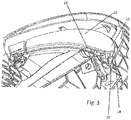
- Fig. 1 shows a side view of an upper portion of the child seat according to the invention according to FIG Fig. 12 .
- the child seat comprises a seat element 10 (seat shell) and a side impact protection element, namely folding element 11, and an unlocking button 12.
- both the folding element 11 and the unlocking button 12 are embedded in an outer surface 13 of the seat element 10, so that the unlocking button 12 and the folding element 11 (see FIG Fig. 2 ) merge at least essentially flush into the adjoining sections of the outer surface of the seat element 10.
- the Figs. 1 and 2 recognizable that the on folding element 11 and Unlock button 12 adjacent sections of the outer surface 13 form a (comparatively flat) projection.
- the folding element is already shifted slightly outwards, which improves the side impact protection.
- the unlocking button 12 is mounted axially, but it can also be a sliding button or be designed differently.
- the release button is preferably designed as a push button.
- the release button 12 or the flap element 11 can also be attached to the outer surface 13 (for example protruding therefrom).
- the folding element 11 is shown with further details.
- the folding element 11 is mounted on an axis 14 via an elongated hole 15 provided in the folding element 11.
- the folding element 11 can on the one hand be rotated about the axis 14 and on the other hand slide with this axis along the elongated hole.
- a receptacle 16 for a proximal end 17 of the folding element 11 can be removed. In this receptacle 16, the folding element can be in its functional position (not in Fig. 3 shown).
- the receptacle 16 (pocket) is designed as a separate part, but can also (directly) be a part of the seat element (the seat shell), that is to say it can be designed in one piece with the outer wall of the seat element.
- a tension spring (not in Fig. 3 to see), which provides a force to rotate the folding element 11 outward when the actuating button 12 is triggered, so that it can assume its functional position.
- Fig. 4 a state is shown which is assumed shortly after the operating button 12 has been triggered. In principle, this is an arbitrarily selected intermediate position during the movement sequence (rotation) for transferring the folding element 11 from the rest position according to FIG Fig. 3 in the functional position according to Fig. 5.
- Fig. 5 thus shows the functional position, ie the end position of the folding element 11. In this position, the proximal end 17 of the folding element 11 is received in the receptacle 16. As in the Fig. 3-5 one can see an end edge 18 at the proximal end 17 of the flap element 11 curved (convex).
- the receptacle 16 is also designed to be curved (concave) in an analogous manner. The proximal end 17 can thereby be supported in the receptacle 16 in a touching manner. Overall, an advantageous form fit is achieved (as explained in detail below).
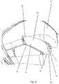
- Fig. 6 shows a section of a side view of the child seat with the folding element 11 pivoted out.
- the seat element 10 has a guide surface 19 along which the proximal end 17 of the folding element 11 can slide while it is being folded out.
- the spring (not visible here) ensures that the proximal end 17 or its end edge 18 is pressed against the guide surface 19.
- the guide surface 19 is also convex (in cross section), that is to say it is curved outward.
- the flap element is designed to be curved, specifically in the proximal-distal direction, which is defined by a direction extending from the proximal end 18 to a distal end 20 (see FIG Fig. 6 ) runs.
- the flap element 11 adapts to the outer wall 13 in a particularly advantageous manner.
- the folding element 11 In a cross section, perpendicular to the proximal-distal direction, the folding element 11 has a flat upper side 21 and a curved lower side 22, "upper” referring to the fact that in the folded-in state this surface faces away from the seat element 10 and accordingly "Lower” refers to the fact that the corresponding surface points towards the seat element in the folded-in state.
- the cross-section of the flap element is approximately crescent-shaped in the proximal-distal direction (the upper side 21 can therefore also be at least slightly concave).
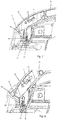
- Fig. 7 Figure 10 shows a cross section of a portion of the child seat.
- the folding element 11 is in its rest position. If the (not in Fig. 7 shown, see for example Figs. 1 and 2 ) Actuation button 12 is pressed, the (also not in the Fig. 7 shown) distal end (see Fig. 6 ) 20 of the folding element 11 freely movable, so that due to the spring force an in Fig. 7 spring element 31 shown, the proximal end 17 of the folding element 11 slides along the receiving or guide surface 19 (this is shown in FIG Fig. 8 shown).
- the spring element 31 acts between the suspension points 32 or engages them (the spring shown in the figures is therefore to be understood purely schematically).
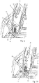
- the flap element 11 rotates about the axis 14 until an in Fig. 9 shown intermediate position is reached. In this intermediate position, the distal end edge 18 is in a position (precisely) between the guide surface 19 and the receptacle 16. If (or because) the spring 31 continues to act, the distal end 17 slides into the receptacle 16 until it reaches the end position (functional position ) in Fig. 10 achieved. During this sliding into the receptacle 16, the axis 14 slides along the elongated hole 15. For this reason, the elongated hole 15 is oriented in the proximal-distal direction.
- Fig. 11 shows the folding part 11 in the functional position. If the folding part 11 is pulled in the direction of the arrow 23, the proximal end 17 moves out of the exception 16 (cf. for the opposite case the Figures 9 and 10 ) so that after reaching the position according to Fig. 9 can be folded back and thus be brought into its rest position. This is done by hand, against the tensile force of the spring, which must therefore be overcome.
- the receptacle 16 (pocket) has the advantage that in the event of a rear-end collision (impact) the folding element 11 is securely supported and held, which overall improves the side impact protection function in a simple manner.
- the present description relates in detail to a side impact protection element or folding element 11 attached to the side.
- a side impact protection element or folding element 11 attached to the side.
Landscapes
- Engineering & Computer Science (AREA)
- Aviation & Aerospace Engineering (AREA)
- Transportation (AREA)
- Mechanical Engineering (AREA)
- Health & Medical Sciences (AREA)
- Child & Adolescent Psychology (AREA)
- General Health & Medical Sciences (AREA)
- Seats For Vehicles (AREA)
Description
- Die Erfindung betrifft einen Kindersitz zur Anbringung auf einem Kraftfahrzeugsitz gemäß Anspruch 1.
- In diesem Zusammenhang sei angemerkt, dass im Rahmen dieser Erfindung der Begriff "Kindersitz" als Oberbegriff für (klassische) Kindersitze und Babyschalen zu verstehen ist. Somit sind für einen Kindersitz vorgesehene Merkmale im Rahmen dieser Erfindung grundsätzlich auch auf eine Babyschale anwendbar und umgekehrt, solange nichts Gegenteiliges erwähnt ist. Selbiges gilt für den Begriff "Kind", der ebenfalls als Oberbegriff für Kinder und Babys sowie Kleinkinder zu verstehen ist.
-
EP 0 958 959 A2 beschreibt einen Kindersitz mit Seitenwangen. - Kindersitze und Babyschalen, die auf einem Kraftfahrzeugsitz angebracht werden können, sind seit geraumer Zeit bekannt. Solche Kindersitze oder Babyschalen dienen als Sitzgelegenheit für Kleinkinder, Babys und Kinder und bieten diesen, insbesondere im Falle eines Unfalls, erhöhten Schutz. Die Befestigung derartiger Kindersitze kann mit dem Gurtsystem des Autos oder mittels Isofix-Klinken erfolgen. Eine derartige Befestigung sichert den Kindersitz im Falle eines Unfalls auf dem Kraftfahrzeugsitz, so dass dieser, insbesondere bei einem Auffahrunfall (Aufprall), auf dem Kraftfahrzeugsitz gehalten und nicht nach vorne geschleudert wird. Als problematisch haben sich diese Sitze jedoch bei einem Seitenaufprall erwiesen, da sowohl eine Gurtbefestigung als auch eine Befestigung mittels Isofix-Klinken den Kindersitz oder die Babyschale nur unzureichend gegen eine Seitwärts-Bewegung des Sitzes schützt. Aus diesem Grund ist es bekannt, den Kindersitz mit einem Seitenaufprallschutz auszustatten, wie beispielsweise in
-
WO 2013/189819 A1 beschrieben, die einen Kindersitz gemäß dem Oberbegriff des Anspruchs 1 zeigt. Bei diesem Kindersitz ist eine Sitzschale und ein an dieser aufgebrachter Seitenaufprallschutz vorgesehen, der von einer Ruhestellung in eine Funktionsstellung gebracht werden kann, wobei der Seitenaufprallschutz so positioniert ist, dass er etwaige Seitenkräfte hinter dem Rücken eines im Kindersitz sitzenden Kindes vorbei überträgt und in die Sitzschale einleitet. - Durch einen derartigen Seitenaufprallschutz wird die Sicherheit erhöht. Die Absicherung gegen die Folgen eines Seitenaufpralls wird jedoch als weiter verbesserungswürdig angesehen.
- Es ist daher Aufgabe der Erfindung einen Seitenaufprallschutz aufzuzeigen, der sich durch eine verbesserte Absicherung gegenüber einem Seitenaufprall auszeichnet, insbesondere die Bedienbarkeit und Einstellung einer Funktionsstellung des Seitenaufprallschutzes vereinfacht.
- Diese Aufgabe wird durch einen Kindersitz gemäß Anspruch 1 gelöst. Weitere Ausführungsformen der Erfindung ergeben sich aus den Unteransprüchen.
- Gemäß der Erfindung wird ein Kindersitz zur Anbringung auf einem Kraftfahrzeugsitz mit einem Sitzelement, insbesondere eine Sitzschale, und einem Seitenaufprallschutz nach Anspruch 1 vorgeschlagen. Die Außenwand des Sitzelementes kann zur (rastenden) Aufnahme (Halterung) des Klappelementes in der Funktionsstellung ausgenutzt werden. Dadurch wird die Struktur des Kindersitzes vereinfacht, was mögliche Fehlfunktionen unwahrscheinlicher macht. Insbesondere werden Fehlfunktionen, die bei der Verwendung eines Halteriegels, wie beispielsweise gemäß
WO 2013/189819 A1 vorgeschlagen, vermieden. - Bei der Standardbreite kann es sich um eine Breite von 440 mm gemäß dem AGREEMENT CONCERNING THE ADOPTION OF UNIFORMED TECHNICAL PRESCRIPTIONS FOR WHEELED VEHICLES, EQUIPEMENT AND PARTS WHICH CAN BE FITTED AND/ OR BE USED ON WHEELED VEHICLES AND THE CONDITIONS FOR RECIPROCAL RECOGNITION OF APPROVALS GRANTED ON THE BASIS OF THESE PRESCRIPTIONS (Revision 2, including the amendments which entered into force on 16 October 1995), E/ECE/324, E/ECE/TRANS/505, Rev. 1/ADD.15/Rev. 6 vom 19. Mai 2009, Annex 17 - Appendix 2, handeln.
- Vorzugsweise weist der Kindersitz eine Stellungsüberführungseinrichtung auf, die derart ausgebildet ist, dass die Stellungsüberführungseinrichtung selbsttätig den Seitenaufprallschutz von seiner Ruhestellung oder einer Zwischenstellung zwischen Ruhe- und Funktionsstellung in seine Funktionsstellung überführt. Dabei wurde erkannt, dass aufgrund des Verbringens oder Überführens in die Funktionsstellung, was gemäß dem Stand der Technik per Hand erfolgt, eine Sicherheitslücke resultiert, beispielsweise wenn eine Arretierung nicht (richtig) ausgelöst oder durchgeführt wird oder nur eine Zwischenstellung zwischen Ruhe- und Funktionsstellung eingestellt wird. Dem Benutzer wird also die Aufgabe von der Stellungsüberführungseinrichtung abgenommen, den Seitenaufprallschutz in seine Funktionsstellung zu überführen. Insgesamt wird die Sicherheit erhöht.
- Vorzugsweise ist eine Betätigungseinrichtung vorgesehen, die derart zum Zusammenwirken mit der Stellungsüberführungseinrichtung ausgebildet ist, dass die Stellungsüberführungseinrichtung selbsttätig den Seitenaufprallschutz von seiner Ruhestellung oder einer Zwischenstellung zwischen Ruhe- und Funktionsstellung überführt, wenn die Betätigungseinrichtung betätigt wird oder wurde. Dadurch wird die Bedienung weiter vereinfacht.
- Unter einer "Zwischenstellung" soll insbesondere eine Stellung verstanden werden, bei der der Seitenaufprallschutz nur zum Teil von der Ruhestellung in die Funktionsstellung überführt wird, beispielsweise nur teilweise aufgeklappt ist (z.B. um einen Winkel, der 10-80%, weiter vorzugsweise 10-60% des gesamten Aufklappwinkels entspricht oder beispielsweise nur teilweise, insbesondere teleskopartig, ausgefahren ist, beispielsweise um 10-90%, insbesondere 10-60% des gesamten Ausfahrweges). Im Allgemeinen kann eine Zwischenstellung dann vorliegen, wenn ein distales Ende des Seitenaufprallschutzes 10-90%, vorzugsweise 10-60% seines Weges in seitlicher Richtung bei der Überführung zwischen Ruhe- in die Funktionsstellung zurückgelegt hat.
- Vorzugsweise handelt es sich bei der Betätigungseinrichtung um einen Betätigungsknopf, insbesondere Druckknopf und/oder Schieberknopf. Dadurch wird die Bedienbarkeit weiter vereinfacht und damit die Sicherheit erhöht.
- Die Betätigungseinrichtung kann in die Außenwand des Sitzelementes eingebettet sein. Insbesondere kann/können das Klappelement und/oder die Betätigungseinrichtung in die Außenwand des Sitzelementes eingeklappt sein. Auf diese Weise kann gewährleistet werden, dass der Kindersitz durch den vorgesehenen Seitenaufprallschutz in der Ruhestellung nicht über eine vorgegebene Breite, insbesondere Standardbreite, respektive Hüllkurve des Kindersitzes hinausragt und bei angelegtem Klappelement eine übliche Breite eines Kindersitzes nicht übersteigt, was die Handhabbarkeit des Kindersitzes zusätzlich begünstigt.
- In einer konkreten Ausführungsform umfasst die Stellungsüberführungseinrichtung mindestens eine Feder, insbesondere Zugfeder. Weiterhin kann ein Langloch zur (gleitenden) Aufnahme einer Rotationsachse, vorzugsweise im Klappelement, vorgesehen sein. Durch eine Feder kann auf einfache Weise eine Kraft bereitgestellt werden, die den Seitenaufprallschutz in seine Funktionsstellung drängt. Ein Langloch zur (gleitenden) Aufnahme einer Rotationsachse (die beispielsweise ortsfest an dem Sitzelement angebracht ist) ermöglicht es auf einfache Art und Weise, das Klappelement gleichzeitig zu rotieren und in seine Funktionsstellung zu überführen (in der es insbesondere arretiert ist). Im Allgemeinen erlaubt ein derartiges Langloch also eine gleichzeitige Rotation und translatorische Verschiebung des Klappelementes. Insgesamt wird die Handhabung weiter vereinfacht.
- Vorzugsweise ist ein proximales Ende des Klappelementes in der Funktionsstellung in einem Halteabschnitt (Halteaufnahme) der Außenwand des Sitzelementes rastend gehalten. Eine Halte- bzw. Rastfunktion wird also durch das Klappelement selbst in Zusammenwirken mit der ohnehin vorgesehenen Außenwand des Sitzelementes ermöglicht.
- Das Klappelement kann in der Funktionsstellung so positioniert und gehalten sein, dass (nur) durch ein Ziehen des Klappelementes (z.B. an einem distalen Ende desselben) eine Überführung in die Ruhestellung möglich ist, insbesondere eine Arretierung in der Funktionsstellung (nur) durch das Ziehen aufgehoben werden kann. Im Allgemeinen erfolgt die Überführung von Funktionsstellung in Ruhestellung nicht selbsttätig (kann jedoch ggf. auch selbsttätig erfolgen), sondern wird per Hand durchgeführt, wie im Stand der Technik auch hinsichtlich der Überführung von Ruhestellung in Funktionsstellung. Dadurch wird das Gesamtsystem weiter vereinfacht. Insbesondere wurde erkannt, dass es im umgekehrten Fall (der Überführung von Funktionsstellung in Ruhestellung) weniger sicherheitsrelevant ist, ob die Ruhestellung letztendlich vollständig erreicht wird oder eine Zwischenstellung vorliegt.
- Das Klappelement, insbesondere ein Abschnitt, der in eine proximal-distale Richtung verläuft, kann gebogen ausgebildet sein. Durch eine gebogene Ausführung des Klappelementes kann dieses platzsparend in die Ruhestellung überführt werden und gleichzeitig effektiv gegen einen Seitenaufprall schützen. Das Klappelement kann in einem Querschnitt senkrecht auf die proximal-distale Richtung, zumindest abschnittsweise, bogenförmig sein. Vorzugsweise weist das Klappelement in einem Querschnitt senkrecht auf die proximal-distale Richtung eine (zumindest im Wesentlichen) flache Oberseite und eine gebogene Unterseite auf. Auch durch derartige Maßnahmen kann das Klappelement effektiv in die Außenwand des Sitzelementes eingebettet werden (was insgesamt eine platzsparende und dennoch effektive Konstruktion ermöglicht). Die proximal-distale Richtung ist durch eine Richtung definier, die von einem proximalen Ende zu einem distalen Ende des Klappelementes verläuft.
- Im Prinzip kann nur ein (Englisch: one) seitlich angebrachtes Seitenaufprallschutzelement bzw. Klappelement vorgesehen sein. Vorteilhafterweise sind jedoch an beiden Seiten des Kindersitzes entsprechende Seitenaufprallschutzelemente vorgesehen. Die (abgesehen von einer Spiegelung der jeweiligen Strukturen) identisch ausgebildet sein können. Es wäre auch denkbar, noch mehr als nur zwei Seitenaufprallschutzelemente (wie oben beschrieben) vorzusehen, beispielsweise je zwei auf beiden Seiten.
- Nachfolgend wird die Erfindung anhand eines Ausführungsbeispiels beschrieben, das anhand der Abbildungen näher erläutert wird. Hierbei zeigen:
- Fig. 1
- einen Ausschnitt des erfindungsgemäßen Kindersitzes in einer schematischen Seitenansicht;
- Fig. 2
- einen weiteren Ausschnitt des Kindersitzes gemäß
Fig. 1 ; - Fig. 3
- einen weiteren Ausschnitt des Kindersitzes, wobei das Innere des Kindersitzes teilweise freigegeben ist;
- Fig. 4
- einen Ausschnitt des Kindersitzes analog
Fig. 3 mit teilweise ausgeklapptem Klappelement; - Fig. 5
- einen Ausschnitt des Kindersitzes analog
Fig. 3 und4 mit vollständig ausgeklapptem Klappelement; - Fig. 6
- einen Ausschnitt des Kindersitzes mit ausgeklapptem Klappelement in einer schematischen Seitenansicht;
- Fig. 7
- einen Schnitt durch einen Abschnitt des Kindersitzes;
- Fig. 8
- einen Schnitt analog
Fig. 7 in einer zweiten Stellung eines Klappelementes; - Fig. 9
- einen Schnitt analog
Fig. 7 und 8 in einer weiteren Stellung des Klappelementes; - Fig. 10
- einen Schnitt analog
Fig. 7-9 in einer Funktionsstellung des Klappelementes; - Fig. 11
- einen Abschnitt des Kindersitzes, wobei die Sicht auf das Innere des Kindersitzes teilweise freigegeben ist; und
- Fig. 12
- eine Seitenansicht des erfindungsgemäßen Kindersitzes.
- In der nachfolgenden Beschreibung werden für gleiche und gleichwirkende Teile dieselben Bezugsziffern verwendet.
-
Fig. 1 zeigt eine Seitenansicht eines oberen Abschnittes des erfindungsgemäßen Kindersitzes gemäßFig. 12 . Der Kindersitz umfasst ein Sitzelement 10 (Sitzschale) sowie ein Seitenaufprallschutzelement, nämlich Klappelement 11, und einen Entriegelungsknopf 12. Wie inFiguren 1 und insbesondere 2 erkennbar, ist sowohl das Klappelement 11 als auch der Entriegelungsknopf 12 in eine Außenfläche 13 des Sitzelementes 10 eingebettet, so dass Entriegelungsknopf 12 und Klappelement 11 (sieheFig. 2 ) zumindest im Wesentlichen bündig in die angrenzenden Abschnitte der Außenfläche des Sitzelementes 10 übergehen. Weiterhin ist in denFig. 1 und 2 erkennbar, dass die an Klappelement 11 und Entriegelungsknopf 12 angrenzenden Abschnitte der Außenfläche 13 einen (vergleichsweise flachen) Vorsprung ausbilden. Dadurch wird das Klappelement bereits etwas nach außen verlagert, was den Seitenaufprallschutz verbessert. - Der Entriegelungsknopf 12 ist ausführungsgemäß axial gelagert, kann jedoch auch ein Schiebeknopf sein oder noch anders ausgeführt sein. Vorzugsweise ist der Entriegelungsknopf jedoch als Druckknopf ausgebildet.
- Entriegelungsknopf 12 oder Klappelement 11 können auch auf der Außenfläche 13 (beispielsweise von dieser vorstehend) angebracht sein.
- In den
Fig. 1 und 2 befindet sich das Klappelement 11 in seiner Ruhestellung. - In der Ansicht gemäß
Fig. 3 , in der teilweise ein Inneres des Kindersitzes einsehbar ist, ist das Klappelement 11 mit weiteren Details gezeigt. Insbesondere ist erkennbar, dass das Klappelement 11 auf einer Achse 14 über ein im Klappelement 11 vorgesehenes Langloch 15 gelagert ist. Dadurch kann das Klappelement 11 einerseits um die Achse 14 rotiert werden und andererseits mit dieser Achse entlang des Langlochs gleiten. Weiterhin kannFig. 3 eine Aufnahme 16 für ein proximales Ende 17 des Klappelementes 11 entnommen werden. In dieser Aufnahme 16 kann das Klappelement in seiner Funktionsstellung (nicht inFig. 3 gezeigt) aufgenommen werden. Die Aufnahme 16 (Tasche) ist ausführungsgemäß als separates Teil ausgebildet, kann jedoch auch (direkt) ein Teil des Sitzelementes (der Sitzschale) sein, also einstückig mit der Außenwand des Sitzelementes ausgebildet sein. Wie im Einzelnen weiter unten erläutert, ist eine Zugfeder (nicht inFig. 3 zu sehen) gezeigt, die eine Kraft bereitstellt, um bei Auslösen des Betätigungsknopfes 12 das Klappelement 11 nach außen zu rotieren, so dass es seine Funktionsstellung einnehmen kann. - In
Fig. 4 ist ein Zustand gezeigt, der eingenommen wird, kurz nachdem der Betätigungsknopf 12 ausgelöst wurde. Es handelt sich hier im Prinzip um eine willkürlich gewählte Zwischenposition, während des Bewegungsablaufs (Rotation) zur Überführung des Klappelements 11 von der Ruhestellung gemäßFig. 3 in die Funktionsstellung gemäßFig. 5. Fig. 5 zeigt also die Funktionsstellung, d.h. die Endposition des Klappelementes 11. In dieser Position ist das proximale Ende 17 des Klappelementes 11 in der Aufnahme 16 aufgenommen. Wie in denFig. 3-5 erkennbar, ist eine Endkante 18 am proximalen Ende 17 des Klappelementes 11 gebogen (konvex) ausgebildet. Analog ist auch die Aufnahme 16 gebogen (konkav) ausgeführt. Das proximale Ende 17 kann dadurch berührend in der Aufnahme 16 gelagert werden. Insgesamt wird ein vorteilhafter Formschluss erreicht (wie nachfolgend im Detail erläutert). -
Fig. 6 zeigt einen Abschnitt einer Seitenansicht des Kindersitzes mit herausgeschwenktem Klappelement 11. Erkennbar ist hier, dass das Sitzelement 10 eine Führungsfläche 19 aufweist, entlang der das proximale Ende 17 des Klappelementes 11 während des Herausklappens entlanggleiten kann. Die (hier nicht erkennbare) Feder sorgt dafür, dass das proximale Ende 17 bzw. dessen Endkante 18 an die Führungsfläche 19 gedrückt wird. Auch die Führungsfläche 19 ist (im Querschnitt) konvex ausgebildet, also nach außen gewölbt. - Wie in den
Fig. 1-6 erkennbar, ist das Klappelement gebogen ausgeführt und zwar in proximal-distale Richtung, die durch eine Richtung definiert wird, die von dem proximalen Ende 18 zu einem distalen Ende 20 (sieheFig. 6 ) verläuft. Dadurch passt sich das Klappelement 11 der Außenwand 13 besonders vorteilhaft an. - In einem Querschnitt, senkrecht auf die proximal-distale Richtung, weist das Klappelement 11 eine flache Oberseite 21 und eine gebogene Unterseite 22 auf, wobei sich "Ober-" darauf bezieht, dass im eingeklappten Zustand diese Fläche von dem Sitzelement 10 weg weist und entsprechend "Unter-" sich darauf bezieht, dass die entsprechende Fläche zu dem Sitzelement im eingeklappten Zustand hin weist. Der Querschnitt des Klappelementes ist in proximal-distaler Richtung etwa halbmondförmig (auch die Oberseite 21 kann also zumindest geringfügig konkav ausgebildet sein).
- Insgesamt sorgt die Führungsfläche 19 (siehe
Fig. 6 ) dafür, dass im Zusammenwirken mit der Feder das Klappelement 11 in seine Funktionsstellung rotiert werden kann. - Das Zusammenwirken mit der Feder lässt sich den
Fig. 7-11 entnehmen.Fig. 7 zeigt einen Querschnitt eines Abschnitts des Kindersitzes. Das Klappelement 11 befindet sich in seiner Ruhestellung. Wird nun der (nicht inFig. 7 gezeigte, siehe beispielsweiseFig. 1 und 2 ) Betätigungsknopf 12 betätigt, wird das (ebenfalls nicht in denFig. 7 gezeigte) distale Ende (sieheFig. 6 ) 20 des Klappelementes 11 frei beweglich, so dass aufgrund der Federkraft eines inFig. 7 gezeigten Federelementes 31 das proximale Ende 17 des Klappelementes 11 entlang der Aufnahme bzw. Führungsfläche 19 gleitet (dies ist inFig. 8 gezeigt). - Zum besseren Verständnis sei angemerkt, dass das Federelement 31 zwischen den Aufhängepunkten 32 wirkt bzw. an diesen angreift (die in den Figuren gezeigte Feder also rein schematisch zu verstehen ist).
- Während des Gleitens des distalen Endes 17 entlang der Führungsfläche 19 rotiert das Klappelement 11 um die Achse 14, bis eine in
Fig. 9 gezeigte Zwischenposition erreicht wird. In dieser Zwischenposition ist die distale Endkante 18 in einer Stellung (genau) zwischen Führungsfläche 19 und Aufnahme 16. Wenn (bzw. weil) die Feder 31 nun weiter wirkt, gleitet das distale Ende 17 in die Aufnahme 16, bis es die Endstellung (Funktionsstellung) inFig. 10 erreicht. Während dieses Hineingleitens in die Aufnahme 16 gleitet die Achse 14 entlang des Langlochs 15. Aus diesem Grund ist das Langloch 15 in proximal-distaler Richtung orientiert. -
Fig. 11 zeigt das Klappteil 11 in der Funktionsstellung. Wird das Klappteil 11 in Richtung des Pfeiles 23 gezogen, bewegt sich das proximale Ende 17 aus der Ausnahme 16 (vgl. für den umgekehrten Fall dieFig. 9 und 10 ), so dass es nach Erreichen der Position gemäßFig. 9 wieder eingeklappt werden kann und somit in seine Ruheposition verbracht werden kann. Dies erfolgt per Hand, entgegen der Zugkraft der Feder, die also überwunden werden muss. - Um das Klappelement (den Arm) wieder in seine flache (geschlossene) Position zu bringen, kann es ausreichen, dass dieser kurz gezogen bzw. angehoben wird und daraufhin in die Verriegelungslage zurückrotiert werden kann.
- Die Aufnahme 16 (Tasche) hat den Vorteil, dass im Falle eines Auffahrunfalls (Aufpralls) das Klappelement 11 sicher abgestützt und gehalten wird, was insgesamt die Seitenaufprallschutzfunktion auf einfache Art und Weise verbessert.
- Die vorliegende Beschreibung bezieht sich im Detail auf ein (Englisch: one) seitlich angebrachtes Seitenaufprallschutzelement bzw. Klappelement 11. Vorteilhafterweise sind jedoch an beiden Seiten des Kindersitzes entsprechende Seitenaufprallschutzelemente vorgesehen. Die (abgesehen von einer Spiegelung der jeweiligen Strukturen) identisch ausgebildet sein können. Es wäre auch denkbar, noch mehr als nur zwei Seitenaufprallschutzelemente (wie oben beschrieben) vorzusehen, beispielsweise je zwei auf beiden Seiten.
-
- 10
- Sitzelement
- 11
- Klappelement
- 12
- Entriegelungsknopf
- 13
- Außenfläche
- 14
- Achse
- 15
- Langloch
- 16
- Aufnahme
- 17
- proximales Ende
- 18
- Endkante
- 19
- Führungsfläche
- 20
- distales Ende
- 21
- Oberseite
- 22
- Unterseite
- 23
- Pfeil
- 31
- Federelement
- 32
- Aufhängepunkt
Claims (11)
- Kindersitz zur Anbringung an einem Kraftfahrzeugsitz, umfassend ein Sitzelement (10), insbesondere eine Sitzschale, und einen Seitenaufprallschutz, der von einer innerhalb einer vorgegebenen Breite, insbesondere Standardbreite, gelegenen Ruhestellung in eine außerhalb der vorgegeben Breite, insbesondere Standardbreite, gelegene Funktionsstellung und umgekehrt bringbar ist, wobei der Seitenaufprallschutz ein Klappelement (11) umfasst, wobei das Klappelement (11) in der Funktionsstellung arretiert ist, gegenüber einem Einklappen, wobei das Klappelement (11) in der Ruhestellung in die Außenwand (13) des Sitzelementes (10) eingebettet ist, und wobei das Klappelement auch in der Funktionsstellung teilweise in einer Außenwand des Sitzelementes eingebettet ist, so dass nur ein Abschnitt des Klappelementes über die Außenwand vorragt, dadurch gekennzeichnet, dass das Klappelement in der Funktionsstellung um mindestens 50%, jedoch höchstens 80% seiner Länge über die Außenwand des Sitzelementes vorragt.
- Kindersitz nach Anspruch 1, dadurch gekennzeichnet, dass der Kindersitz eine Stellungsüberführungseinrichtung aufweist, die derart ausgebildet ist, dass die Stellungsüberführungseinrichtung selbsttätig den Seitenaufprallschutz von seiner Ruhestellung oder einer Zwischenstellung zwischen Ruhe- und Funktionsstellung in seine Funktionsstellung überführt.
- Kindersitz nach Anspruch 2, dadurch gekennzeichnet, dass der Kindersitz eine Betätigungseinrichtung aufweist, die derart mit der Stellungsüberführungseinrichtung zusammenwirken kann, dass, wenn die Betätigungseinrichtung betätigt wird, die Stellungsüberführungseinrichtung selbsttätig den Seitenaufprallschutz von seiner Ruhestellung oder einer Zwischenstellung zwischen seiner Ruhe- und Funktionsstellung in seine Funktionsstellung überführt.
- Kindersitz nach Anspruch 3, dadurch gekennzeichnet, dass die Betätigungseinrichtung einen Betätigungsknopf (12), vorzugsweise einen Entriegelungsknopf, insbesondere Druckknopf oder Schiebeknopf, umfasst.
- Kindersitz nach Anspruch 4, dadurch gekennzeichnet, dass die Betätigungseinrichtung (12) in der Ruhestellung in die Außenwand (13) des Sitzelementes (10) eingebettet ist.
- Kindersitz nach einem der vorhergehenden Ansprüche 2 bis 5, dadurch gekennzeichnet, dass die Stellungsüberführungseinrichtung mindestens eine Feder (31), insbesondere Zugfeder umfasst und/oder ein Langloch (15), vorzugsweise im Klappelement (11), zur Aufnahme einer Rotationsachse (14).
- Kindersitz nach einem der vorhergehenden Ansprüche, dadurch gekennzeichnet, dass
ein proximales Ende (17) des Klappelementes (11) in der Funktionsstellung in einer Aufnahme der Außenwand (13) des Sitzelementes (10), rastend gehalten ist. - Kindersitz nach einem der vorhergehenden Ansprüche, dadurch gekennzeichnet, dass
eine proximale Endkante (18) des Klappelementes (11) zumindest abschnittsweise konvex ausgebildet ist. - Kindersitz nach einem der vorhergehenden Ansprüche, dadurch gekennzeichnet, dass
das Klappelement (11) in der Funktionsstellung so positioniert und gehalten ist, dass (nur) durch ein Ziehen des Klappelementes, beispielsweise an seinem distalen Ende, eine Überführung in die Ruhestellung möglich ist, insbesondere eine Arretierung in der Funktionsstellung (nur) durch das Ziehen aufgehoben werden kann. - Kindersitz nach einem der vorhergehenden Ansprüche, dadurch gekennzeichnet, dass
das Klappelement (11) insbesondere in einem Abschnitt, der in eine proximal-distale Richtung verläuft, gebogen ausgebildet ist und/oder in einem Querschnitt senkrecht auf die proximal-distale Richtung, zumindest abschnittsweise bogenförmig ist, insbesondere eine (zumindest im Wesentlichen) flache Oberseite und eine gebogene Unterseite aufweist. - Kindersitz nach einem der vorhergehenden Ansprüche, dadurch gekennzeichnet, dass
das Klappelement über mindestens 70% seiner Länge über die Außenwand des Sitzelementes vorragt.
Priority Applications (2)
| Application Number | Priority Date | Filing Date | Title |
|---|---|---|---|
| PL20182276T PL3753781T3 (pl) | 2015-09-09 | 2016-09-09 | Fotelik dziecięcy do montownia na siedzeniu pojazdu |
| EP21200734.8A EP3957520B1 (de) | 2015-09-09 | 2016-09-09 | Kindersitz zur anbringung auf einem kraftfahrzeugsitz |
Applications Claiming Priority (4)
| Application Number | Priority Date | Filing Date | Title |
|---|---|---|---|
| DE202015104791.6U DE202015104791U1 (de) | 2015-09-09 | 2015-09-09 | Kindersitz zur Anbringung auf einem Kraftfahrzeugsitz |
| EP16763050.8A EP3347233B1 (de) | 2015-09-09 | 2016-09-09 | Kindersitz zur anbringung auf einem kraftfahrzeugsitz |
| EP19173486.2A EP3564068B1 (de) | 2015-09-09 | 2016-09-09 | Kindersitz zur anbringung auf einem kraftfahrzeugsitz |
| PCT/EP2016/071288 WO2017042326A1 (de) | 2015-09-09 | 2016-09-09 | Kindersitz zur anbringung auf einem kraftfahrzeugsitz |
Related Parent Applications (3)
| Application Number | Title | Priority Date | Filing Date |
|---|---|---|---|
| EP16763050.8A Division EP3347233B1 (de) | 2015-09-09 | 2016-09-09 | Kindersitz zur anbringung auf einem kraftfahrzeugsitz |
| EP19173486.2A Division EP3564068B1 (de) | 2015-09-09 | 2016-09-09 | Kindersitz zur anbringung auf einem kraftfahrzeugsitz |
| EP19173486.2A Division-Into EP3564068B1 (de) | 2015-09-09 | 2016-09-09 | Kindersitz zur anbringung auf einem kraftfahrzeugsitz |
Related Child Applications (2)
| Application Number | Title | Priority Date | Filing Date |
|---|---|---|---|
| EP21200734.8A Division-Into EP3957520B1 (de) | 2015-09-09 | 2016-09-09 | Kindersitz zur anbringung auf einem kraftfahrzeugsitz |
| EP21200734.8A Division EP3957520B1 (de) | 2015-09-09 | 2016-09-09 | Kindersitz zur anbringung auf einem kraftfahrzeugsitz |
Publications (2)
| Publication Number | Publication Date |
|---|---|
| EP3753781A1 EP3753781A1 (de) | 2020-12-23 |
| EP3753781B1 true EP3753781B1 (de) | 2021-11-10 |
Family
ID=54866524
Family Applications (4)
| Application Number | Title | Priority Date | Filing Date |
|---|---|---|---|
| EP19173486.2A Active EP3564068B1 (de) | 2015-09-09 | 2016-09-09 | Kindersitz zur anbringung auf einem kraftfahrzeugsitz |
| EP16763050.8A Active EP3347233B1 (de) | 2015-09-09 | 2016-09-09 | Kindersitz zur anbringung auf einem kraftfahrzeugsitz |
| EP21200734.8A Active EP3957520B1 (de) | 2015-09-09 | 2016-09-09 | Kindersitz zur anbringung auf einem kraftfahrzeugsitz |
| EP20182276.4A Active EP3753781B1 (de) | 2015-09-09 | 2016-09-09 | Kindersitz zur anbringung auf einem kraftfahrzeugsitz |
Family Applications Before (3)
| Application Number | Title | Priority Date | Filing Date |
|---|---|---|---|
| EP19173486.2A Active EP3564068B1 (de) | 2015-09-09 | 2016-09-09 | Kindersitz zur anbringung auf einem kraftfahrzeugsitz |
| EP16763050.8A Active EP3347233B1 (de) | 2015-09-09 | 2016-09-09 | Kindersitz zur anbringung auf einem kraftfahrzeugsitz |
| EP21200734.8A Active EP3957520B1 (de) | 2015-09-09 | 2016-09-09 | Kindersitz zur anbringung auf einem kraftfahrzeugsitz |
Country Status (11)
| Country | Link |
|---|---|
| US (1) | US10414297B2 (de) |
| EP (4) | EP3564068B1 (de) |
| JP (2) | JP6748193B2 (de) |
| KR (1) | KR102523574B1 (de) |
| CN (1) | CN108025661A (de) |
| BR (1) | BR112018003890B1 (de) |
| DE (4) | DE202015104791U1 (de) |
| DK (1) | DK3347233T3 (de) |
| ES (3) | ES2794558T3 (de) |
| PL (3) | PL3753781T3 (de) |
| WO (1) | WO2017042326A1 (de) |
Families Citing this family (20)
| Publication number | Priority date | Publication date | Assignee | Title |
|---|---|---|---|---|
| DE202015104791U1 (de) | 2015-09-09 | 2015-11-26 | Cybex Gmbh | Kindersitz zur Anbringung auf einem Kraftfahrzeugsitz |
| DE102016111608B4 (de) * | 2016-06-24 | 2018-10-25 | Curt Würstl Vermögensverwaltungs-Gmbh & Co. Kg | Kindersitz mit Seitenaufprallschutz |
| DE102017124014A1 (de) * | 2017-10-16 | 2019-04-18 | Recaro Child Safety Gmbh & Co. Kg | Kindersitzsystem |
| CN113910996B (zh) * | 2017-12-07 | 2023-12-26 | 宝钜儿童用品香港股份有限公司 | 侧撞保护装置及具有该侧撞保护装置的儿童安全座椅 |
| US10857968B2 (en) * | 2017-12-07 | 2020-12-08 | Bambino Prezioso Switzerland Ag | Lateral shock absorber and child car safety seat therewith |
| CN108790970A (zh) * | 2018-05-04 | 2018-11-13 | 好孩子儿童用品有限公司 | 一种防侧撞的儿童安全座椅 |
| WO2020017833A1 (en) | 2018-07-16 | 2020-01-23 | Dong-In Entech Co., Ltd. | Portable car seat |
| CN115352332A (zh) * | 2018-10-01 | 2022-11-18 | 明门瑞士股份有限公司 | 汽车安全座椅及其侧撞保护机构 |
| CN111845481B (zh) * | 2019-04-26 | 2022-12-20 | 宝钜瑞士股份有限公司 | 儿童安全座椅 |
| CN115675211A (zh) * | 2019-04-26 | 2023-02-03 | 宝钜瑞士股份有限公司 | 侧撞保护机构及儿童安全座椅 |
| CN111845483B (zh) * | 2019-04-29 | 2023-09-12 | 明门瑞士股份有限公司 | 侧撞保护装置及儿童安全座椅 |
| CN110254303A (zh) * | 2019-06-19 | 2019-09-20 | 好孩子儿童用品有限公司 | 儿童安全座椅 |
| CN112238798B (zh) * | 2019-07-18 | 2023-03-28 | 明门瑞士股份有限公司 | 侧撞保护机构及儿童安全座椅 |
| CN112810509B (zh) * | 2019-11-15 | 2023-02-17 | 宝钜瑞士股份有限公司 | 侧撞保护连动机构及安全座椅底座 |
| CN113386639A (zh) * | 2020-03-13 | 2021-09-14 | 宝钜瑞士股份有限公司 | 儿童安全座椅 |
| CN113815502A (zh) * | 2020-06-19 | 2021-12-21 | 宝钜瑞士股份有限公司 | 儿童安全座椅及其侧撞保护机构 |
| CN114248668A (zh) * | 2020-09-25 | 2022-03-29 | 宝钜瑞士股份有限公司 | 儿童安全座椅及其侧撞保护装置 |
| DE202020106236U1 (de) | 2020-10-30 | 2022-02-01 | Cybex Gmbh | Kindersitz zur Anbringung auf einem Kraftfahrzeugsitz |
| AU2021201210B1 (en) | 2021-02-24 | 2021-07-29 | BRITAX RÖMER Kindersicherheit GmbH | Child safety seat |
| WO2024061943A1 (de) * | 2022-09-23 | 2024-03-28 | Cybex Gmbh | Kindersitz zur anbringung auf einem kraftfahrzeugsitz |
Citations (10)
| Publication number | Priority date | Publication date | Assignee | Title |
|---|---|---|---|---|
| DE19814920A1 (de) | 1998-04-03 | 1999-10-07 | Bsrs Restraint Syst Gmbh | Mechanische Stützvorrichtung für einen Sitz eines Kraftfahrzeuges gegen die Seitenstrukturen des Fahrzeuges |
| EP0958959A2 (de) | 1998-05-18 | 1999-11-24 | Britax Child Safety Inc. | Kinder-Sicherheitssitz |
| DE10136309C1 (de) | 2001-04-25 | 2002-11-07 | Weber Jos Gmbh & Co Kg | Ascher für Fahrzeuge oder dergleichen |
| EP1927502A1 (de) | 2006-11-28 | 2008-06-04 | Wonderland Nurserygoods Co., Ltd. | Fahrzeugkindersicherheitssitz |
| WO2009111362A2 (en) | 2008-03-03 | 2009-09-11 | Gm Global Technology Operations, Inc. | Manipulable seat bolster utilizing active material actuation |
| CN201587341U (zh) | 2009-12-28 | 2010-09-22 | 好孩子儿童用品有限公司 | 儿童汽车座 |
| EP2275303A1 (de) | 2009-07-14 | 2011-01-19 | BRITAX RÖMER Kindersicherheit GmbH | Kindersitz mit Seitenaufprallschutz |
| DE102012005691A1 (de) | 2012-03-21 | 2013-09-26 | Audi Ag | Verstellvorrichtung für an einem Fahrzeugsitz beidseitig verschwenkbar angeordnete Seitenwangen |
| WO2013189819A1 (de) | 2012-06-18 | 2013-12-27 | Cybex Gmbh | Kindersitz oder babyschale zur anbringung auf einem kraftfahrzeugsitz sowie seitenaufprallschutz für einen solchen sitz |
| CN104709125A (zh) | 2015-01-22 | 2015-06-17 | 上海延锋江森座椅有限公司 | 带有侧防护和提升座垫的集成式儿童汽车座椅 |
Family Cites Families (6)
| Publication number | Priority date | Publication date | Assignee | Title |
|---|---|---|---|---|
| JP3997565B2 (ja) * | 1997-06-20 | 2007-10-24 | トヨタ紡織株式会社 | 車両用シートのヘッドレスト装置 |
| JP4837881B2 (ja) * | 2003-01-14 | 2011-12-14 | ユニ・チャーム株式会社 | 蓋付き容器 |
| GB0513459D0 (en) * | 2005-07-01 | 2005-08-10 | Britax Excelsior | Child support |
| ES2560974T3 (es) * | 2012-12-21 | 2016-02-23 | Britax Childcare Pty Ltd. | Protección contra impactos laterales mecánicos para un dispositivo de retención infantil |
| CN203032420U (zh) * | 2013-01-05 | 2013-07-03 | 好孩子儿童用品有限公司 | 具有侧向防撞系统的儿童座椅 |
| DE202015104791U1 (de) | 2015-09-09 | 2015-11-26 | Cybex Gmbh | Kindersitz zur Anbringung auf einem Kraftfahrzeugsitz |
-
2015
- 2015-09-09 DE DE202015104791.6U patent/DE202015104791U1/de not_active Ceased
-
2016
- 2016-09-09 US US15/756,505 patent/US10414297B2/en active Active
- 2016-09-09 EP EP19173486.2A patent/EP3564068B1/de active Active
- 2016-09-09 PL PL20182276T patent/PL3753781T3/pl unknown
- 2016-09-09 EP EP16763050.8A patent/EP3347233B1/de active Active
- 2016-09-09 PL PL19173486T patent/PL3564068T3/pl unknown
- 2016-09-09 EP EP21200734.8A patent/EP3957520B1/de active Active
- 2016-09-09 JP JP2018512541A patent/JP6748193B2/ja active Active
- 2016-09-09 KR KR1020187006951A patent/KR102523574B1/ko active IP Right Grant
- 2016-09-09 DE DE202016008894.8U patent/DE202016008894U1/de active Active
- 2016-09-09 DE DE202016008731.3U patent/DE202016008731U1/de active Active
- 2016-09-09 WO PCT/EP2016/071288 patent/WO2017042326A1/de active Application Filing
- 2016-09-09 BR BR112018003890-3A patent/BR112018003890B1/pt active IP Right Grant
- 2016-09-09 ES ES16763050T patent/ES2794558T3/es active Active
- 2016-09-09 DK DK16763050.8T patent/DK3347233T3/da active
- 2016-09-09 ES ES20182276T patent/ES2906253T3/es active Active
- 2016-09-09 EP EP20182276.4A patent/EP3753781B1/de active Active
- 2016-09-09 DE DE202016008675.9U patent/DE202016008675U1/de active Active
- 2016-09-09 PL PL16763050T patent/PL3347233T3/pl unknown
- 2016-09-09 CN CN201680052253.0A patent/CN108025661A/zh active Pending
- 2016-09-09 ES ES19173486T patent/ES2834645T3/es active Active
-
2020
- 2020-08-06 JP JP2020133647A patent/JP7348147B2/ja active Active
Patent Citations (10)
| Publication number | Priority date | Publication date | Assignee | Title |
|---|---|---|---|---|
| DE19814920A1 (de) | 1998-04-03 | 1999-10-07 | Bsrs Restraint Syst Gmbh | Mechanische Stützvorrichtung für einen Sitz eines Kraftfahrzeuges gegen die Seitenstrukturen des Fahrzeuges |
| EP0958959A2 (de) | 1998-05-18 | 1999-11-24 | Britax Child Safety Inc. | Kinder-Sicherheitssitz |
| DE10136309C1 (de) | 2001-04-25 | 2002-11-07 | Weber Jos Gmbh & Co Kg | Ascher für Fahrzeuge oder dergleichen |
| EP1927502A1 (de) | 2006-11-28 | 2008-06-04 | Wonderland Nurserygoods Co., Ltd. | Fahrzeugkindersicherheitssitz |
| WO2009111362A2 (en) | 2008-03-03 | 2009-09-11 | Gm Global Technology Operations, Inc. | Manipulable seat bolster utilizing active material actuation |
| EP2275303A1 (de) | 2009-07-14 | 2011-01-19 | BRITAX RÖMER Kindersicherheit GmbH | Kindersitz mit Seitenaufprallschutz |
| CN201587341U (zh) | 2009-12-28 | 2010-09-22 | 好孩子儿童用品有限公司 | 儿童汽车座 |
| DE102012005691A1 (de) | 2012-03-21 | 2013-09-26 | Audi Ag | Verstellvorrichtung für an einem Fahrzeugsitz beidseitig verschwenkbar angeordnete Seitenwangen |
| WO2013189819A1 (de) | 2012-06-18 | 2013-12-27 | Cybex Gmbh | Kindersitz oder babyschale zur anbringung auf einem kraftfahrzeugsitz sowie seitenaufprallschutz für einen solchen sitz |
| CN104709125A (zh) | 2015-01-22 | 2015-06-17 | 上海延锋江森座椅有限公司 | 带有侧防护和提升座垫的集成式儿童汽车座椅 |
Also Published As
| Publication number | Publication date |
|---|---|
| EP3753781A1 (de) | 2020-12-23 |
| US20180244178A1 (en) | 2018-08-30 |
| WO2017042326A1 (de) | 2017-03-16 |
| DE202016008731U1 (de) | 2019-04-18 |
| JP7348147B2 (ja) | 2023-09-20 |
| PL3753781T3 (pl) | 2022-05-16 |
| JP6748193B2 (ja) | 2020-08-26 |
| DE202015104791U1 (de) | 2015-11-26 |
| ES2834645T3 (es) | 2021-06-18 |
| BR112018003890B1 (pt) | 2022-07-26 |
| EP3564068A1 (de) | 2019-11-06 |
| DE202016008894U1 (de) | 2020-07-03 |
| PL3347233T3 (pl) | 2020-10-19 |
| DE202016008675U1 (de) | 2018-12-12 |
| JP2018526279A (ja) | 2018-09-13 |
| DK3347233T3 (da) | 2020-07-20 |
| EP3957520A1 (de) | 2022-02-23 |
| KR20180050663A (ko) | 2018-05-15 |
| EP3957520B1 (de) | 2024-05-29 |
| ES2906253T3 (es) | 2022-04-13 |
| EP3564068B1 (de) | 2020-09-09 |
| BR112018003890A2 (pt) | 2018-09-25 |
| JP2020196441A (ja) | 2020-12-10 |
| US10414297B2 (en) | 2019-09-17 |
| EP3347233B1 (de) | 2020-04-22 |
| EP3347233A1 (de) | 2018-07-18 |
| ES2794558T3 (es) | 2020-11-18 |
| PL3564068T3 (pl) | 2021-04-06 |
| CN108025661A (zh) | 2018-05-11 |
| KR102523574B1 (ko) | 2023-04-18 |
Similar Documents
| Publication | Publication Date | Title |
|---|---|---|
| EP3753781B1 (de) | Kindersitz zur anbringung auf einem kraftfahrzeugsitz | |
| EP2861455B1 (de) | Kindersitz oder babyschale zur anbringung auf einem kraftfahrzeugsitz | |
| DE102016120455A1 (de) | Kinderwagenvorrichtung | |
| DE102013103326B4 (de) | Kindersitzvorrichtung und deren Verwendung | |
| EP2768697B1 (de) | Verriegelungs- und neigungsverstellanordnung, insbesondere lehnenschloss | |
| DE102009048649A1 (de) | Mit einem Autositz verbindbarer Kinderwagen | |
| EP1762459B1 (de) | Fahrgestell für einen Kinder- oder Puppenwagen sowie Kinder- oder Puppenwagen | |
| DE102010002601A1 (de) | Drehverriegelungsmechanismus für eine Kopfstütze | |
| WO2014075819A1 (de) | Fahrzeugsitz, insbesondere kraftfahrzeugsitz | |
| DE102019110321A1 (de) | Kindersitz | |
| EP2004448B1 (de) | Verstellsystem für einen fahrzeugsitz | |
| DE19947621B4 (de) | Sitz für ein Fortbewegungsmittel | |
| DE102010043658A1 (de) | Türschlosskonstruktion | |
| DE102020112104A1 (de) | Längseinsteller für einen Sitz, insbesondere Fahrzeugsitz | |
| DE102011015688A1 (de) | Fahrzeugsitz | |
| DE202020106236U1 (de) | Kindersitz zur Anbringung auf einem Kraftfahrzeugsitz | |
| DE202012100936U1 (de) | Sitzlängsversteller für einen Fahrzeugsitz mit Einstiegserleichterungsfunktionalität und Klappfunktionalität | |
| WO2024061943A1 (de) | Kindersitz zur anbringung auf einem kraftfahrzeugsitz |
Legal Events
| Date | Code | Title | Description |
|---|---|---|---|
| PUAI | Public reference made under article 153(3) epc to a published international application that has entered the european phase |
Free format text: ORIGINAL CODE: 0009012 |
|
| STAA | Information on the status of an ep patent application or granted ep patent |
Free format text: STATUS: THE APPLICATION HAS BEEN PUBLISHED |
|
| AC | Divisional application: reference to earlier application |
Ref document number: 3347233 Country of ref document: EP Kind code of ref document: P Ref document number: 3564068 Country of ref document: EP Kind code of ref document: P |
|
| AK | Designated contracting states |
Kind code of ref document: A1 Designated state(s): AL AT BE BG CH CY CZ DE DK EE ES FI FR GB GR HR HU IE IS IT LI LT LU LV MC MK MT NL NO PL PT RO RS SE SI SK SM TR |
|
| STAA | Information on the status of an ep patent application or granted ep patent |
Free format text: STATUS: REQUEST FOR EXAMINATION WAS MADE |
|
| 17P | Request for examination filed |
Effective date: 20210203 |
|
| RBV | Designated contracting states (corrected) |
Designated state(s): AL AT BE BG CH CY CZ DE DK EE ES FI FR GB GR HR HU IE IS IT LI LT LU LV MC MK MT NL NO PL PT RO RS SE SI SK SM TR |
|
| GRAP | Despatch of communication of intention to grant a patent |
Free format text: ORIGINAL CODE: EPIDOSNIGR1 |
|
| STAA | Information on the status of an ep patent application or granted ep patent |
Free format text: STATUS: GRANT OF PATENT IS INTENDED |
|
| INTG | Intention to grant announced |
Effective date: 20210514 |
|
| GRAS | Grant fee paid |
Free format text: ORIGINAL CODE: EPIDOSNIGR3 |
|
| GRAA | (expected) grant |
Free format text: ORIGINAL CODE: 0009210 |
|
| STAA | Information on the status of an ep patent application or granted ep patent |
Free format text: STATUS: THE PATENT HAS BEEN GRANTED |
|
| AC | Divisional application: reference to earlier application |
Ref document number: 3347233 Country of ref document: EP Kind code of ref document: P Ref document number: 3564068 Country of ref document: EP Kind code of ref document: P |
|
| AK | Designated contracting states |
Kind code of ref document: B1 Designated state(s): AL AT BE BG CH CY CZ DE DK EE ES FI FR GB GR HR HU IE IS IT LI LT LU LV MC MK MT NL NO PL PT RO RS SE SI SK SM TR |
|
| REG | Reference to a national code |
Ref country code: GB Ref legal event code: FG4D Free format text: NOT ENGLISH |
|
| REG | Reference to a national code |
Ref country code: AT Ref legal event code: REF Ref document number: 1445787 Country of ref document: AT Kind code of ref document: T Effective date: 20211115 Ref country code: CH Ref legal event code: EP |
|
| REG | Reference to a national code |
Ref country code: IE Ref legal event code: FG4D Free format text: LANGUAGE OF EP DOCUMENT: GERMAN |
|
| REG | Reference to a national code |
Ref country code: DE Ref legal event code: R096 Ref document number: 502016014151 Country of ref document: DE |
|
| REG | Reference to a national code |
Ref country code: NL Ref legal event code: FP |
|
| REG | Reference to a national code |
Ref country code: LT Ref legal event code: MG9D |
|
| REG | Reference to a national code |
Ref country code: ES Ref legal event code: FG2A Ref document number: 2906253 Country of ref document: ES Kind code of ref document: T3 Effective date: 20220413 |
|
| PG25 | Lapsed in a contracting state [announced via postgrant information from national office to epo] |
Ref country code: RS Free format text: LAPSE BECAUSE OF FAILURE TO SUBMIT A TRANSLATION OF THE DESCRIPTION OR TO PAY THE FEE WITHIN THE PRESCRIBED TIME-LIMIT Effective date: 20211110 Ref country code: LT Free format text: LAPSE BECAUSE OF FAILURE TO SUBMIT A TRANSLATION OF THE DESCRIPTION OR TO PAY THE FEE WITHIN THE PRESCRIBED TIME-LIMIT Effective date: 20211110 Ref country code: FI Free format text: LAPSE BECAUSE OF FAILURE TO SUBMIT A TRANSLATION OF THE DESCRIPTION OR TO PAY THE FEE WITHIN THE PRESCRIBED TIME-LIMIT Effective date: 20211110 Ref country code: BG Free format text: LAPSE BECAUSE OF FAILURE TO SUBMIT A TRANSLATION OF THE DESCRIPTION OR TO PAY THE FEE WITHIN THE PRESCRIBED TIME-LIMIT Effective date: 20220210 |
|
| PG25 | Lapsed in a contracting state [announced via postgrant information from national office to epo] |
Ref country code: IS Free format text: LAPSE BECAUSE OF FAILURE TO SUBMIT A TRANSLATION OF THE DESCRIPTION OR TO PAY THE FEE WITHIN THE PRESCRIBED TIME-LIMIT Effective date: 20220310 Ref country code: SE Free format text: LAPSE BECAUSE OF FAILURE TO SUBMIT A TRANSLATION OF THE DESCRIPTION OR TO PAY THE FEE WITHIN THE PRESCRIBED TIME-LIMIT Effective date: 20211110 Ref country code: PT Free format text: LAPSE BECAUSE OF FAILURE TO SUBMIT A TRANSLATION OF THE DESCRIPTION OR TO PAY THE FEE WITHIN THE PRESCRIBED TIME-LIMIT Effective date: 20220310 Ref country code: NO Free format text: LAPSE BECAUSE OF FAILURE TO SUBMIT A TRANSLATION OF THE DESCRIPTION OR TO PAY THE FEE WITHIN THE PRESCRIBED TIME-LIMIT Effective date: 20220210 Ref country code: LV Free format text: LAPSE BECAUSE OF FAILURE TO SUBMIT A TRANSLATION OF THE DESCRIPTION OR TO PAY THE FEE WITHIN THE PRESCRIBED TIME-LIMIT Effective date: 20211110 Ref country code: HR Free format text: LAPSE BECAUSE OF FAILURE TO SUBMIT A TRANSLATION OF THE DESCRIPTION OR TO PAY THE FEE WITHIN THE PRESCRIBED TIME-LIMIT Effective date: 20211110 Ref country code: GR Free format text: LAPSE BECAUSE OF FAILURE TO SUBMIT A TRANSLATION OF THE DESCRIPTION OR TO PAY THE FEE WITHIN THE PRESCRIBED TIME-LIMIT Effective date: 20220211 |
|
| PG25 | Lapsed in a contracting state [announced via postgrant information from national office to epo] |
Ref country code: SM Free format text: LAPSE BECAUSE OF FAILURE TO SUBMIT A TRANSLATION OF THE DESCRIPTION OR TO PAY THE FEE WITHIN THE PRESCRIBED TIME-LIMIT Effective date: 20211110 Ref country code: SK Free format text: LAPSE BECAUSE OF FAILURE TO SUBMIT A TRANSLATION OF THE DESCRIPTION OR TO PAY THE FEE WITHIN THE PRESCRIBED TIME-LIMIT Effective date: 20211110 Ref country code: RO Free format text: LAPSE BECAUSE OF FAILURE TO SUBMIT A TRANSLATION OF THE DESCRIPTION OR TO PAY THE FEE WITHIN THE PRESCRIBED TIME-LIMIT Effective date: 20211110 Ref country code: EE Free format text: LAPSE BECAUSE OF FAILURE TO SUBMIT A TRANSLATION OF THE DESCRIPTION OR TO PAY THE FEE WITHIN THE PRESCRIBED TIME-LIMIT Effective date: 20211110 Ref country code: DK Free format text: LAPSE BECAUSE OF FAILURE TO SUBMIT A TRANSLATION OF THE DESCRIPTION OR TO PAY THE FEE WITHIN THE PRESCRIBED TIME-LIMIT Effective date: 20211110 Ref country code: CZ Free format text: LAPSE BECAUSE OF FAILURE TO SUBMIT A TRANSLATION OF THE DESCRIPTION OR TO PAY THE FEE WITHIN THE PRESCRIBED TIME-LIMIT Effective date: 20211110 |
|
| REG | Reference to a national code |
Ref country code: DE Ref legal event code: R026 Ref document number: 502016014151 Country of ref document: DE |
|
| PLBI | Opposition filed |
Free format text: ORIGINAL CODE: 0009260 |
|
| PLAB | Opposition data, opponent's data or that of the opponent's representative modified |
Free format text: ORIGINAL CODE: 0009299OPPO |
|
| PLAX | Notice of opposition and request to file observation + time limit sent |
Free format text: ORIGINAL CODE: EPIDOSNOBS2 |
|
| 26 | Opposition filed |
Opponent name: WONDERLAND NURSERYGOODS COMPANY LTD. Effective date: 20220810 |
|
| R26 | Opposition filed (corrected) |
Opponent name: WONDERLAND NURSERYGOODS COMPANY LTD. Effective date: 20220810 |
|
| PG25 | Lapsed in a contracting state [announced via postgrant information from national office to epo] |
Ref country code: AL Free format text: LAPSE BECAUSE OF FAILURE TO SUBMIT A TRANSLATION OF THE DESCRIPTION OR TO PAY THE FEE WITHIN THE PRESCRIBED TIME-LIMIT Effective date: 20211110 |
|
| PG25 | Lapsed in a contracting state [announced via postgrant information from national office to epo] |
Ref country code: SI Free format text: LAPSE BECAUSE OF FAILURE TO SUBMIT A TRANSLATION OF THE DESCRIPTION OR TO PAY THE FEE WITHIN THE PRESCRIBED TIME-LIMIT Effective date: 20211110 |
|
| PLBB | Reply of patent proprietor to notice(s) of opposition received |
Free format text: ORIGINAL CODE: EPIDOSNOBS3 |
|
| PG25 | Lapsed in a contracting state [announced via postgrant information from national office to epo] |
Ref country code: MC Free format text: LAPSE BECAUSE OF FAILURE TO SUBMIT A TRANSLATION OF THE DESCRIPTION OR TO PAY THE FEE WITHIN THE PRESCRIBED TIME-LIMIT Effective date: 20211110 |
|
| REG | Reference to a national code |
Ref country code: CH Ref legal event code: PL |
|
| REG | Reference to a national code |
Ref country code: BE Ref legal event code: MM Effective date: 20220930 |
|
| PG25 | Lapsed in a contracting state [announced via postgrant information from national office to epo] |
Ref country code: LU Free format text: LAPSE BECAUSE OF NON-PAYMENT OF DUE FEES Effective date: 20220909 |
|
| PG25 | Lapsed in a contracting state [announced via postgrant information from national office to epo] |
Ref country code: LI Free format text: LAPSE BECAUSE OF NON-PAYMENT OF DUE FEES Effective date: 20220930 Ref country code: IE Free format text: LAPSE BECAUSE OF NON-PAYMENT OF DUE FEES Effective date: 20220909 Ref country code: CH Free format text: LAPSE BECAUSE OF NON-PAYMENT OF DUE FEES Effective date: 20220930 |
|
| PG25 | Lapsed in a contracting state [announced via postgrant information from national office to epo] |
Ref country code: BE Free format text: LAPSE BECAUSE OF NON-PAYMENT OF DUE FEES Effective date: 20220930 |
|
| PGFP | Annual fee paid to national office [announced via postgrant information from national office to epo] |
Ref country code: TR Payment date: 20230905 Year of fee payment: 8 Ref country code: NL Payment date: 20230926 Year of fee payment: 8 Ref country code: GB Payment date: 20230926 Year of fee payment: 8 |
|
| REG | Reference to a national code |
Ref country code: AT Ref legal event code: MM01 Ref document number: 1445787 Country of ref document: AT Kind code of ref document: T Effective date: 20220909 |
|
| PGFP | Annual fee paid to national office [announced via postgrant information from national office to epo] |
Ref country code: PL Payment date: 20230905 Year of fee payment: 8 Ref country code: FR Payment date: 20230926 Year of fee payment: 8 Ref country code: DE Payment date: 20230929 Year of fee payment: 8 |
|
| PGFP | Annual fee paid to national office [announced via postgrant information from national office to epo] |
Ref country code: ES Payment date: 20231017 Year of fee payment: 8 |
|
| PG25 | Lapsed in a contracting state [announced via postgrant information from national office to epo] |
Ref country code: AT Free format text: LAPSE BECAUSE OF NON-PAYMENT OF DUE FEES Effective date: 20220909 |
|
| PGFP | Annual fee paid to national office [announced via postgrant information from national office to epo] |
Ref country code: IT Payment date: 20230925 Year of fee payment: 8 |
|
| PG25 | Lapsed in a contracting state [announced via postgrant information from national office to epo] |
Ref country code: CY Free format text: LAPSE BECAUSE OF FAILURE TO SUBMIT A TRANSLATION OF THE DESCRIPTION OR TO PAY THE FEE WITHIN THE PRESCRIBED TIME-LIMIT Effective date: 20211110 |