EP3733307B1 - Method and device for producing a decorative surface - Google Patents
Method and device for producing a decorative surface Download PDFInfo
- Publication number
- EP3733307B1 EP3733307B1 EP19208738.5A EP19208738A EP3733307B1 EP 3733307 B1 EP3733307 B1 EP 3733307B1 EP 19208738 A EP19208738 A EP 19208738A EP 3733307 B1 EP3733307 B1 EP 3733307B1
- Authority
- EP
- European Patent Office
- Prior art keywords
- layer
- manipulation
- brush
- removal
- workpiece
- Prior art date
- Legal status (The legal status is an assumption and is not a legal conclusion. Google has not performed a legal analysis and makes no representation as to the accuracy of the status listed.)
- Active
Links
- 238000000034 method Methods 0.000 title claims description 59
- 239000007788 liquid Substances 0.000 claims description 68
- 230000005855 radiation Effects 0.000 claims description 51
- 239000012530 fluid Substances 0.000 claims description 44
- 230000005670 electromagnetic radiation Effects 0.000 claims description 20
- 239000007787 solid Substances 0.000 claims description 19
- 238000010438 heat treatment Methods 0.000 claims description 10
- 238000000227 grinding Methods 0.000 claims description 9
- 238000004140 cleaning Methods 0.000 claims description 8
- 239000000835 fiber Substances 0.000 claims description 8
- 238000004519 manufacturing process Methods 0.000 claims description 7
- 238000001035 drying Methods 0.000 claims description 6
- 239000002184 metal Substances 0.000 claims description 5
- 229910052751 metal Inorganic materials 0.000 claims description 5
- 239000004033 plastic Substances 0.000 claims description 5
- 229910001369 Brass Inorganic materials 0.000 claims description 4
- RYGMFSIKBFXOCR-UHFFFAOYSA-N Copper Chemical compound [Cu] RYGMFSIKBFXOCR-UHFFFAOYSA-N 0.000 claims description 4
- 229910000831 Steel Inorganic materials 0.000 claims description 4
- 239000010951 brass Substances 0.000 claims description 4
- 229910052802 copper Inorganic materials 0.000 claims description 4
- 239000010949 copper Substances 0.000 claims description 4
- 229920001778 nylon Polymers 0.000 claims description 4
- 238000007639 printing Methods 0.000 claims description 4
- 239000010959 steel Substances 0.000 claims description 4
- 239000004753 textile Substances 0.000 claims description 4
- 238000006243 chemical reaction Methods 0.000 claims description 3
- 238000009966 trimming Methods 0.000 claims 1
- 239000003795 chemical substances by application Substances 0.000 description 77
- 239000000463 material Substances 0.000 description 30
- 238000001723 curing Methods 0.000 description 25
- 230000008569 process Effects 0.000 description 11
- XLYOFNOQVPJJNP-UHFFFAOYSA-N water Substances O XLYOFNOQVPJJNP-UHFFFAOYSA-N 0.000 description 9
- 230000000694 effects Effects 0.000 description 5
- CURLTUGMZLYLDI-UHFFFAOYSA-N Carbon dioxide Chemical compound O=C=O CURLTUGMZLYLDI-UHFFFAOYSA-N 0.000 description 4
- 235000011089 carbon dioxide Nutrition 0.000 description 4
- 239000000126 substance Substances 0.000 description 4
- 238000005516 engineering process Methods 0.000 description 3
- 239000003595 mist Substances 0.000 description 3
- 239000000203 mixture Substances 0.000 description 3
- 238000005266 casting Methods 0.000 description 2
- 230000008859 change Effects 0.000 description 2
- 238000000605 extraction Methods 0.000 description 2
- 238000006116 polymerization reaction Methods 0.000 description 2
- 238000003847 radiation curing Methods 0.000 description 2
- 239000004576 sand Substances 0.000 description 2
- 238000007790 scraping Methods 0.000 description 2
- 239000002023 wood Substances 0.000 description 2
- NIXOWILDQLNWCW-UHFFFAOYSA-M Acrylate Chemical compound [O-]C(=O)C=C NIXOWILDQLNWCW-UHFFFAOYSA-M 0.000 description 1
- UIIMBOGNXHQVGW-DEQYMQKBSA-M Sodium bicarbonate-14C Chemical compound [Na+].O[14C]([O-])=O UIIMBOGNXHQVGW-DEQYMQKBSA-M 0.000 description 1
- 150000001252 acrylic acid derivatives Chemical class 0.000 description 1
- 239000000654 additive Substances 0.000 description 1
- 239000012298 atmosphere Substances 0.000 description 1
- 230000008901 benefit Effects 0.000 description 1
- 239000011230 binding agent Substances 0.000 description 1
- 230000015572 biosynthetic process Effects 0.000 description 1
- 230000000739 chaotic effect Effects 0.000 description 1
- 238000005352 clarification Methods 0.000 description 1
- 238000009833 condensation Methods 0.000 description 1
- 230000005494 condensation Effects 0.000 description 1
- 238000001514 detection method Methods 0.000 description 1
- 238000011161 development Methods 0.000 description 1
- 230000018109 developmental process Effects 0.000 description 1
- 238000010894 electron beam technology Methods 0.000 description 1
- 238000001704 evaporation Methods 0.000 description 1
- 230000001678 irradiating effect Effects 0.000 description 1
- 230000007774 longterm Effects 0.000 description 1
- 238000003754 machining Methods 0.000 description 1
- 239000012299 nitrogen atmosphere Substances 0.000 description 1
- 239000000049 pigment Substances 0.000 description 1
- 238000012545 processing Methods 0.000 description 1
- 230000001681 protective effect Effects 0.000 description 1
- 230000001105 regulatory effect Effects 0.000 description 1
- 239000000725 suspension Substances 0.000 description 1
- 229920002994 synthetic fiber Polymers 0.000 description 1
- 238000012546 transfer Methods 0.000 description 1
- 230000007704 transition Effects 0.000 description 1
Images


Classifications
-
- A—HUMAN NECESSITIES
- A46—BRUSHWARE
- A46B—BRUSHES
- A46B13/00—Brushes with driven brush bodies or carriers
- A46B13/001—Cylindrical or annular brush bodies
-
- A—HUMAN NECESSITIES
- A46—BRUSHWARE
- A46B—BRUSHES
- A46B5/00—Brush bodies; Handles integral with brushware
- A46B5/06—Brush bodies; Handles integral with brushware in the form of tapes, chains, flexible shafts, springs, mats or the like
-
- B—PERFORMING OPERATIONS; TRANSPORTING
- B05—SPRAYING OR ATOMISING IN GENERAL; APPLYING FLUENT MATERIALS TO SURFACES, IN GENERAL
- B05B—SPRAYING APPARATUS; ATOMISING APPARATUS; NOZZLES
- B05B1/00—Nozzles, spray heads or other outlets, with or without auxiliary devices such as valves, heating means
- B05B1/02—Nozzles, spray heads or other outlets, with or without auxiliary devices such as valves, heating means designed to produce a jet, spray, or other discharge of particular shape or nature, e.g. in single drops, or having an outlet of particular shape
-
- B—PERFORMING OPERATIONS; TRANSPORTING
- B05—SPRAYING OR ATOMISING IN GENERAL; APPLYING FLUENT MATERIALS TO SURFACES, IN GENERAL
- B05D—PROCESSES FOR APPLYING FLUENT MATERIALS TO SURFACES, IN GENERAL
- B05D1/00—Processes for applying liquids or other fluent materials
- B05D1/02—Processes for applying liquids or other fluent materials performed by spraying
-
- B—PERFORMING OPERATIONS; TRANSPORTING
- B05—SPRAYING OR ATOMISING IN GENERAL; APPLYING FLUENT MATERIALS TO SURFACES, IN GENERAL
- B05D—PROCESSES FOR APPLYING FLUENT MATERIALS TO SURFACES, IN GENERAL
- B05D1/00—Processes for applying liquids or other fluent materials
- B05D1/32—Processes for applying liquids or other fluent materials using means for protecting parts of a surface not to be coated, e.g. using stencils, resists
-
- B—PERFORMING OPERATIONS; TRANSPORTING
- B05—SPRAYING OR ATOMISING IN GENERAL; APPLYING FLUENT MATERIALS TO SURFACES, IN GENERAL
- B05D—PROCESSES FOR APPLYING FLUENT MATERIALS TO SURFACES, IN GENERAL
- B05D1/00—Processes for applying liquids or other fluent materials
- B05D1/40—Distributing applied liquids or other fluent materials by members moving relatively to surface
- B05D1/42—Distributing applied liquids or other fluent materials by members moving relatively to surface by non-rotary members
-
- B—PERFORMING OPERATIONS; TRANSPORTING
- B05—SPRAYING OR ATOMISING IN GENERAL; APPLYING FLUENT MATERIALS TO SURFACES, IN GENERAL
- B05D—PROCESSES FOR APPLYING FLUENT MATERIALS TO SURFACES, IN GENERAL
- B05D3/00—Pretreatment of surfaces to which liquids or other fluent materials are to be applied; After-treatment of applied coatings, e.g. intermediate treating of an applied coating preparatory to subsequent applications of liquids or other fluent materials
- B05D3/007—After-treatment
-
- B—PERFORMING OPERATIONS; TRANSPORTING
- B05—SPRAYING OR ATOMISING IN GENERAL; APPLYING FLUENT MATERIALS TO SURFACES, IN GENERAL
- B05D—PROCESSES FOR APPLYING FLUENT MATERIALS TO SURFACES, IN GENERAL
- B05D3/00—Pretreatment of surfaces to which liquids or other fluent materials are to be applied; After-treatment of applied coatings, e.g. intermediate treating of an applied coating preparatory to subsequent applications of liquids or other fluent materials
- B05D3/04—Pretreatment of surfaces to which liquids or other fluent materials are to be applied; After-treatment of applied coatings, e.g. intermediate treating of an applied coating preparatory to subsequent applications of liquids or other fluent materials by exposure to gases
-
- B—PERFORMING OPERATIONS; TRANSPORTING
- B05—SPRAYING OR ATOMISING IN GENERAL; APPLYING FLUENT MATERIALS TO SURFACES, IN GENERAL
- B05D—PROCESSES FOR APPLYING FLUENT MATERIALS TO SURFACES, IN GENERAL
- B05D3/00—Pretreatment of surfaces to which liquids or other fluent materials are to be applied; After-treatment of applied coatings, e.g. intermediate treating of an applied coating preparatory to subsequent applications of liquids or other fluent materials
- B05D3/06—Pretreatment of surfaces to which liquids or other fluent materials are to be applied; After-treatment of applied coatings, e.g. intermediate treating of an applied coating preparatory to subsequent applications of liquids or other fluent materials by exposure to radiation
- B05D3/061—Pretreatment of surfaces to which liquids or other fluent materials are to be applied; After-treatment of applied coatings, e.g. intermediate treating of an applied coating preparatory to subsequent applications of liquids or other fluent materials by exposure to radiation using U.V.
- B05D3/065—After-treatment
- B05D3/067—Curing or cross-linking the coating
-
- B—PERFORMING OPERATIONS; TRANSPORTING
- B05—SPRAYING OR ATOMISING IN GENERAL; APPLYING FLUENT MATERIALS TO SURFACES, IN GENERAL
- B05D—PROCESSES FOR APPLYING FLUENT MATERIALS TO SURFACES, IN GENERAL
- B05D3/00—Pretreatment of surfaces to which liquids or other fluent materials are to be applied; After-treatment of applied coatings, e.g. intermediate treating of an applied coating preparatory to subsequent applications of liquids or other fluent materials
- B05D3/12—Pretreatment of surfaces to which liquids or other fluent materials are to be applied; After-treatment of applied coatings, e.g. intermediate treating of an applied coating preparatory to subsequent applications of liquids or other fluent materials by mechanical means
-
- B—PERFORMING OPERATIONS; TRANSPORTING
- B05—SPRAYING OR ATOMISING IN GENERAL; APPLYING FLUENT MATERIALS TO SURFACES, IN GENERAL
- B05D—PROCESSES FOR APPLYING FLUENT MATERIALS TO SURFACES, IN GENERAL
- B05D5/00—Processes for applying liquids or other fluent materials to surfaces to obtain special surface effects, finishes or structures
- B05D5/02—Processes for applying liquids or other fluent materials to surfaces to obtain special surface effects, finishes or structures to obtain a matt or rough surface
-
- B—PERFORMING OPERATIONS; TRANSPORTING
- B08—CLEANING
- B08B—CLEANING IN GENERAL; PREVENTION OF FOULING IN GENERAL
- B08B1/00—Cleaning by methods involving the use of tools
- B08B1/20—Cleaning of moving articles, e.g. of moving webs or of objects on a conveyor
-
- B—PERFORMING OPERATIONS; TRANSPORTING
- B08—CLEANING
- B08B—CLEANING IN GENERAL; PREVENTION OF FOULING IN GENERAL
- B08B1/00—Cleaning by methods involving the use of tools
- B08B1/30—Cleaning by methods involving the use of tools by movement of cleaning members over a surface
-
- B—PERFORMING OPERATIONS; TRANSPORTING
- B08—CLEANING
- B08B—CLEANING IN GENERAL; PREVENTION OF FOULING IN GENERAL
- B08B3/00—Cleaning by methods involving the use or presence of liquid or steam
- B08B3/02—Cleaning by the force of jets or sprays
- B08B3/022—Cleaning travelling work
-
- B—PERFORMING OPERATIONS; TRANSPORTING
- B08—CLEANING
- B08B—CLEANING IN GENERAL; PREVENTION OF FOULING IN GENERAL
- B08B5/00—Cleaning by methods involving the use of air flow or gas flow
- B08B5/02—Cleaning by the force of jets, e.g. blowing-out cavities
- B08B5/023—Cleaning travelling work
-
- B—PERFORMING OPERATIONS; TRANSPORTING
- B24—GRINDING; POLISHING
- B24B—MACHINES, DEVICES, OR PROCESSES FOR GRINDING OR POLISHING; DRESSING OR CONDITIONING OF ABRADING SURFACES; FEEDING OF GRINDING, POLISHING, OR LAPPING AGENTS
- B24B21/00—Machines or devices using grinding or polishing belts; Accessories therefor
- B24B21/04—Machines or devices using grinding or polishing belts; Accessories therefor for grinding plane surfaces
-
- B—PERFORMING OPERATIONS; TRANSPORTING
- B24—GRINDING; POLISHING
- B24B—MACHINES, DEVICES, OR PROCESSES FOR GRINDING OR POLISHING; DRESSING OR CONDITIONING OF ABRADING SURFACES; FEEDING OF GRINDING, POLISHING, OR LAPPING AGENTS
- B24B53/00—Devices or means for dressing or conditioning abrasive surfaces
- B24B53/003—Devices or means for dressing or conditioning abrasive surfaces using at least two conditioning tools
-
- B—PERFORMING OPERATIONS; TRANSPORTING
- B24—GRINDING; POLISHING
- B24B—MACHINES, DEVICES, OR PROCESSES FOR GRINDING OR POLISHING; DRESSING OR CONDITIONING OF ABRADING SURFACES; FEEDING OF GRINDING, POLISHING, OR LAPPING AGENTS
- B24B7/00—Machines or devices designed for grinding plane surfaces on work, including polishing plane glass surfaces; Accessories therefor
- B24B7/10—Single-purpose machines or devices
- B24B7/18—Single-purpose machines or devices for grinding floorings, walls, ceilings or the like
-
- B—PERFORMING OPERATIONS; TRANSPORTING
- B24—GRINDING; POLISHING
- B24B—MACHINES, DEVICES, OR PROCESSES FOR GRINDING OR POLISHING; DRESSING OR CONDITIONING OF ABRADING SURFACES; FEEDING OF GRINDING, POLISHING, OR LAPPING AGENTS
- B24B7/00—Machines or devices designed for grinding plane surfaces on work, including polishing plane glass surfaces; Accessories therefor
- B24B7/10—Single-purpose machines or devices
- B24B7/19—Single-purpose machines or devices for grinding plane decorative patterns
-
- B—PERFORMING OPERATIONS; TRANSPORTING
- B24—GRINDING; POLISHING
- B24C—ABRASIVE OR RELATED BLASTING WITH PARTICULATE MATERIAL
- B24C1/00—Methods for use of abrasive blasting for producing particular effects; Use of auxiliary equipment in connection with such methods
- B24C1/04—Methods for use of abrasive blasting for producing particular effects; Use of auxiliary equipment in connection with such methods for treating only selected parts of a surface, e.g. for carving stone or glass
-
- B—PERFORMING OPERATIONS; TRANSPORTING
- B24—GRINDING; POLISHING
- B24C—ABRASIVE OR RELATED BLASTING WITH PARTICULATE MATERIAL
- B24C3/00—Abrasive blasting machines or devices; Plants
- B24C3/08—Abrasive blasting machines or devices; Plants essentially adapted for abrasive blasting of travelling stock or travelling workpieces
-
- B—PERFORMING OPERATIONS; TRANSPORTING
- B24—GRINDING; POLISHING
- B24C—ABRASIVE OR RELATED BLASTING WITH PARTICULATE MATERIAL
- B24C9/00—Appurtenances of abrasive blasting machines or devices, e.g. working chambers, arrangements for handling used abrasive material
-
- B—PERFORMING OPERATIONS; TRANSPORTING
- B27—WORKING OR PRESERVING WOOD OR SIMILAR MATERIAL; NAILING OR STAPLING MACHINES IN GENERAL
- B27D—WORKING VENEER OR PLYWOOD
- B27D1/00—Joining wood veneer with any material; Forming articles thereby; Preparatory processing of surfaces to be joined, e.g. scoring
- B27D1/04—Joining wood veneer with any material; Forming articles thereby; Preparatory processing of surfaces to be joined, e.g. scoring to produce plywood or articles made therefrom; Plywood sheets
-
- B—PERFORMING OPERATIONS; TRANSPORTING
- B29—WORKING OF PLASTICS; WORKING OF SUBSTANCES IN A PLASTIC STATE IN GENERAL
- B29C—SHAPING OR JOINING OF PLASTICS; SHAPING OF MATERIAL IN A PLASTIC STATE, NOT OTHERWISE PROVIDED FOR; AFTER-TREATMENT OF THE SHAPED PRODUCTS, e.g. REPAIRING
- B29C59/00—Surface shaping of articles, e.g. embossing; Apparatus therefor
- B29C59/02—Surface shaping of articles, e.g. embossing; Apparatus therefor by mechanical means, e.g. pressing
-
- B—PERFORMING OPERATIONS; TRANSPORTING
- B29—WORKING OF PLASTICS; WORKING OF SUBSTANCES IN A PLASTIC STATE IN GENERAL
- B29C—SHAPING OR JOINING OF PLASTICS; SHAPING OF MATERIAL IN A PLASTIC STATE, NOT OTHERWISE PROVIDED FOR; AFTER-TREATMENT OF THE SHAPED PRODUCTS, e.g. REPAIRING
- B29C59/00—Surface shaping of articles, e.g. embossing; Apparatus therefor
- B29C59/16—Surface shaping of articles, e.g. embossing; Apparatus therefor by wave energy or particle radiation, e.g. infrared heating
-
- B—PERFORMING OPERATIONS; TRANSPORTING
- B41—PRINTING; LINING MACHINES; TYPEWRITERS; STAMPS
- B41M—PRINTING, DUPLICATING, MARKING, OR COPYING PROCESSES; COLOUR PRINTING
- B41M5/00—Duplicating or marking methods; Sheet materials for use therein
- B41M5/0041—Digital printing on surfaces other than ordinary paper
-
- B—PERFORMING OPERATIONS; TRANSPORTING
- B44—DECORATIVE ARTS
- B44C—PRODUCING DECORATIVE EFFECTS; MOSAICS; TARSIA WORK; PAPERHANGING
- B44C1/00—Processes, not specifically provided for elsewhere, for producing decorative surface effects
- B44C1/22—Removing surface-material, e.g. by engraving, by etching
- B44C1/222—Removing surface-material, e.g. by engraving, by etching using machine-driven mechanical means
-
- B—PERFORMING OPERATIONS; TRANSPORTING
- B44—DECORATIVE ARTS
- B44C—PRODUCING DECORATIVE EFFECTS; MOSAICS; TARSIA WORK; PAPERHANGING
- B44C3/00—Processes, not specifically provided for elsewhere, for producing ornamental structures
- B44C3/005—Removing selectively parts of at least the upper layer of a multi-layer article
-
- B—PERFORMING OPERATIONS; TRANSPORTING
- B44—DECORATIVE ARTS
- B44C—PRODUCING DECORATIVE EFFECTS; MOSAICS; TARSIA WORK; PAPERHANGING
- B44C3/00—Processes, not specifically provided for elsewhere, for producing ornamental structures
- B44C3/02—Superimposing layers
- B44C3/025—Superimposing layers to produce ornamental relief structures
-
- B—PERFORMING OPERATIONS; TRANSPORTING
- B44—DECORATIVE ARTS
- B44D—PAINTING OR ARTISTIC DRAWING, NOT OTHERWISE PROVIDED FOR; PRESERVING PAINTINGS; SURFACE TREATMENT TO OBTAIN SPECIAL ARTISTIC SURFACE EFFECTS OR FINISHES
- B44D5/00—Surface treatment to obtain special artistic surface effects or finishes
-
- B—PERFORMING OPERATIONS; TRANSPORTING
- B08—CLEANING
- B08B—CLEANING IN GENERAL; PREVENTION OF FOULING IN GENERAL
- B08B15/00—Preventing escape of dirt or fumes from the area where they are produced; Collecting or removing dirt or fumes from that area
- B08B15/04—Preventing escape of dirt or fumes from the area where they are produced; Collecting or removing dirt or fumes from that area from a small area, e.g. a tool
-
- B—PERFORMING OPERATIONS; TRANSPORTING
- B08—CLEANING
- B08B—CLEANING IN GENERAL; PREVENTION OF FOULING IN GENERAL
- B08B7/00—Cleaning by methods not provided for in a single other subclass or a single group in this subclass
- B08B7/0035—Cleaning by methods not provided for in a single other subclass or a single group in this subclass by radiant energy, e.g. UV, laser, light beam or the like
- B08B7/0057—Cleaning by methods not provided for in a single other subclass or a single group in this subclass by radiant energy, e.g. UV, laser, light beam or the like by ultraviolet radiation
-
- B—PERFORMING OPERATIONS; TRANSPORTING
- B24—GRINDING; POLISHING
- B24B—MACHINES, DEVICES, OR PROCESSES FOR GRINDING OR POLISHING; DRESSING OR CONDITIONING OF ABRADING SURFACES; FEEDING OF GRINDING, POLISHING, OR LAPPING AGENTS
- B24B29/00—Machines or devices for polishing surfaces on work by means of tools made of soft or flexible material with or without the application of solid or liquid polishing agents
- B24B29/005—Machines or devices for polishing surfaces on work by means of tools made of soft or flexible material with or without the application of solid or liquid polishing agents using brushes
-
- B—PERFORMING OPERATIONS; TRANSPORTING
- B29—WORKING OF PLASTICS; WORKING OF SUBSTANCES IN A PLASTIC STATE IN GENERAL
- B29C—SHAPING OR JOINING OF PLASTICS; SHAPING OF MATERIAL IN A PLASTIC STATE, NOT OTHERWISE PROVIDED FOR; AFTER-TREATMENT OF THE SHAPED PRODUCTS, e.g. REPAIRING
- B29C59/00—Surface shaping of articles, e.g. embossing; Apparatus therefor
- B29C59/02—Surface shaping of articles, e.g. embossing; Apparatus therefor by mechanical means, e.g. pressing
- B29C2059/027—Grinding; Polishing
Definitions
- the present invention relates to a method and a device for machining a surface of a workpiece, in particular for producing a decorative surface.
- the EP 3 109 056 A1 describes, for example, a method for producing a structure on a surface. To do this, a liquid layer is applied to a workpiece. A manipulation agent in the form of droplets is then sprayed onto the liquid layer, whereby the droplets displace the liquid layer so that depressions are formed in it, which together form a structure in the liquid layer. This layer is then fixed. In this way, a surface can be created on the layer that has, for example, a wood or tile look.
- the EP 3 415 316 A1 discloses a method in which a manipulation agent is applied to the liquid layer in the form of droplets or fine droplets, the manipulation agent having the property of at least partially absorbing electromagnetic radiation.
- a manipulation agent When the liquid layer is irradiated, for example with an excimer laser, polymerization takes place on the surface of the liquid layer, causing micro-folding there, which later results in a matte surface.
- the manipulation agent on the surface of the The liquid layer absorbs the radiation at least partially, so that polymerization takes place less strongly here. As a result, these areas are shinier than the areas where no manipulation agent was present.
- the US 2016 / 0 114 619 A1 shows several methods and devices for producing structured surfaces.
- a production step is disclosed in which parts of the surface of a synthetic material layer or an applied manipulation agent are removed by means of suction.
- the temporarily applied manipulation agent must be removed again after the method has been carried out.
- the problem here is that the manipulation agent, especially if it has bonded to the layer, must be removed reliably and as completely as possible. It is therefore the object of the present invention to solve this problem.
- a further object of this present invention is to enable partial removal of the previously applied layer, in particular at the locations where the manipulation agent has been applied.
- a manipulation agent is applied to and/or into an at least partially liquid layer located on a workpiece.
- the manipulation agent is preferably applied to partial areas or partial regions of the liquid layer and/or the workpiece.
- parts of the layer are removed. The removal takes place mechanical and/or contactless, especially fluidic.
- the layer is at least partially cured together with the manipulation agent before the removal of parts of the layer is carried out, so that in particular the viscosity of the layer increases.
- process steps can be provided in a process for producing a decorative surface on a workpiece.
- process steps can also be a time pause between the removal of parts of the layer and the previously carried out process steps, so that it can also be an independent process, especially the removal of parts of the layer.
- the parts of the layer that are removed also include parts of the manipulation means located on or in the layer.
- this is exclusively the manipulation means. If the manipulation means is removed from the layer, this can be done partially, so that a residue of the manipulation means remains on and/or in the layer. However, the removal can also be done completely, so that the manipulation means is completely removed.
- removing parts of the layer can mean that material from the layer itself is removed.
- only the manipulation device can be removed from the layer.
- both material from the layer itself and material from the manipulation device can also be removed.
- the mechanical removal of parts of the layer is carried out with a removal device which has a contact element which is in contact with the surface of the layer, wherein the surface of the layer and the contact element move relative to each other during removal.
- a parallel movement or a different relative movement can also occur.
- the contact element preferably has a stationary and/or moving brush and/or a grinding and/or a planing element, wherein the contact element is provided in a moving or stationary manner relative to the workpiece.
- the brush preferably has at least as a moving brush a disk brush and/or a roller brush and/or a brush belt and/or as a stationary brush a bar with brush trim.
- the grinding and/or planing element is preferably designed to remove parts of the layer again in order to expose manipulation means enclosed therein.
- the manipulation means can then be removed by means of the grinding and/or planing element or by means of other methods described here.
- the grinding element can preferably comprise a belt grinder.
- the contact element can have a stationary and/or a moving element.
- the contact element is further preferably designed as a cyclically operating contact element, which has, for example, a grinding belt or a roller brush.
- the contact element advantageously has sections that are not cyclically in contact with the layer during removal. These sections can be cleaned at this moment, as described further below.
- the contact element in particular the brush, preferably comprises textile and/or plastic fibers, in particular nylon fibers, and/or metal, in particular steel, brass or copper.
- fibers containing an abrasive can also be used. These are preferably fibers with Anderlon. These fibers or materials are preferably contained in the bristles of the brush. This means that brush designs with metal or plastic bristles are possible.
- the brush preferably has bristles which have a diameter of 0.05 to 2 mm, preferably 0.1 to 1.2 mm, more preferably 0.2 to 0.7 mm, particularly preferably 0.2 to 0.3 mm.
- the removal of parts of the layer comprises suctioning off the parts by means of negative pressure, preferably by means of a suction device.
- the removal of parts of the layer includes heating the layer and/or the manipulation means.
- the heating is carried out by supplying heat to at least partially liquefy the parts of the layer, in particular the manipulation means.
- the heat can preferably be supplied by a heater or an IR radiator.
- the contact element is moved in a controlled and/or regulated manner.
- This can be, for example, the positioning of the contact element relative to the layer, or an adjustment of the rotational speed or the rotational speed of the disc brushes or the brush belt.
- the contact element removes parts of the layer
- the contact element can become clogged by the removed material of the layer and/or the manipulation means. In the case of a brush, this means that the removed material becomes stuck in the bristles.
- a grinding and/or planing element can also be affected by clogging under certain circumstances.
- a further step can therefore be provided in which the contact element is cleaned. The entire process for cleaning the contact element, which is described below, can also be carried out independently of the process described in this application.
- Cleaning can preferably be carried out by mechanically stripping the material on a stripping edge and/or by suction using negative pressure, for example by the suction device mentioned above or another suction device.
- a supply of heat to the contact element can also be provided here.
- the heat supply can preferably be carried out by a heater or an IR radiator.
- the heater can be provided in the contact element, for example.
- the cleaning of the contact element can include irradiating the contact element with radiation, in particular electromagnetic radiation and/or electron radiation, during the removal of the manipulation agent and/or parts of the previously applied layer.
- radiation in particular electromagnetic radiation and/or electron radiation
- This in particular ensures that the material and/or the manipulation agent that had adhered to the contact element is at least partially or completely hardened and is then in a hard and brittle form.
- the hardening of the material preferably ensures that it can be easily detached from the contact element, in particular from the bristles if a brush is provided. This material can be removed from the contact element again by mechanical stripping and/or suction.
- a stripping edge can be provided, for example, along which the added contact element can be guided, whereby the manipulation means and/or the removed part of the layer can be stripped off. If the contact element has a brush, for example, the bristles of the brush can come into contact with the stripping edge.
- the material that clogs the contact element is in particular material of the layer and/or the manipulation means, in principle any process can be used that in particular involves hardening or a change in the viscosity of these materials. Therefore, reference is made to the options described in this application.
- the material and/or the manipulation agent has a proportion of more than 70% of acrylates, which crosslink through the formation of chemical bonds when exposed to electromagnetic radiation, thus reducing the viscosity and thus also the stickiness of the material and/or the manipulation agent and increasing the brittleness. Therefore, the embodiment of cleaning the contact element described above is well suited to ensuring long-term and less susceptible to failure operation of an industrial plant producing according to the method according to the invention.
- the material and/or the manipulation means may also comprise or be formed from other components, such as an aqueous mixture with binders, pigments and other additives.
- the removal of parts of the layer comprises passing a fluid stream, in particular an air stream, over the surface of the layer and/or the manipulation means.
- the manipulation means in particular can be removed without contact, which is advantageously gentle on the surface of the layer.
- workpieces can also be processed that have elements that can be damaged by non-contact methods, for example by contact with a brush described above.
- a workpiece 1 is shown in the form of a pre-milled plank with a layer 2 applied to the workpiece surface.
- the workpiece 1 has a connecting element 1a, which can engage in a groove of another workpiece as a tongue in the sense of a tongue-and-groove connection in order to join several workpieces together, for example as a floor covering.
- so-called "click profiles" are now used instead of tongue and groove for laying floorboards, which are used, for example, in the EP 2 280 130 A2
- These areas, or the transition area from the connecting element to layer 2 should not be subjected to unnecessary mechanical stress during production. Contactless removal of parts of the layer is therefore particularly advantageous here.
- the process can preferably also be used for surfaces outside of the floor covering, e.g. for furniture, wall, ceiling surfaces or also for external facade elements or other applications.
- the fluid flow impinges on the surface of the layer and/or the manipulation means in a correspondingly shaped manner so that it extends over the entire width of the layer.
- the length of the impact surface of the fluid flow in the direction of movement of the workpiece is preferably 1% to 20%, particularly preferably 5% to 15%, in particular 10% to 12%, of the length of the fluid flow transverse to the direction of movement.
- a fluid flow that is as thin as possible is preferably used, in particular in the sense of an "air blade” or an "air knife”.
- a liquid flow, in particular containing water can also be used as the fluid flow.
- the fluid flow hits the layer and/or the manipulation agent at an angle that is less than 45°, preferably less than 30°, particularly preferably less than 15°.
- a flat flow is useful in order to achieve detachment from the layer, for example if only the manipulation agent is to be removed.
- a steeper angle of the fluid flow may also be useful, for example to blow out manipulation agent contained in depressions in the layer.
- the angle is changed while the method is being carried out, particularly preferably changed periodically. The change can preferably also be made depending on the currently detected amount of the manipulation agent removed. This amount is preferably detected by a detection device that, for example, detects the weight of the manipulation agent that was removed.
- the fluid flow can also hit the surface of the layer through so-called rotating nozzles.
- the rotating nozzles which direct the fluid flow onto the surface, rotate around a central axis, with a total diameter of the rotating nozzles of preferably 2-120 mm, particularly preferably 5-50 mm. This directs a temporally variable fluid flow onto the surface.
- the fluid flow also contains solids that improve the removal of parts of the layer.
- this can contain sand or a similar substance that acts on the surface of the layer and/or the manipulation means in addition to the fluid flow.
- the fluid flow can therefore also be used to remove material from the layer in addition to the manipulation means.
- the solid bodies preferably have a diameter of 0.0001 to 1 mm, preferably 0.001 to 0.5 mm, particularly preferably 0.005 to 0.3 mm.
- the solid bodies are designed to liquefy or evaporate after hitting the layer and/or the manipulation means.
- This can be achieved, for example, by the solid bodies having the property of evaporating at the ambient temperature to which the workpiece with the layer is exposed.
- this can be achieved using solid bodies made of dry ice.
- These can be applied to the surface of the layer and/or the manipulation means in particular using a dry ice blaster. This advantageously ensures that the solid bodies do not remain on and/or in the layer. This means that subsequent removal of the solid bodies from the layer is not necessary.
- the solid bodies are exposed to a liquid, in particular water, during the generation of the fluid flow.
- a liquid in particular water
- the exposure can be achieved, for example, by This can be done by moving the solids with the fluid flow through a mist of liquid.
- the solids then act as condensation nuclei to which components of the mist adhere, which ultimately causes the solid to be exposed to the liquid.
- the solids can specifically include grains of sand, dry ice (solid CO2), water ice (frozen water), sodium bicarbonate, or mixtures of these solids.
- the layer and/or the manipulation means are preferably designed to be polymerizable by means of electromagnetic radiation.
- the applied manipulation agent can also be completely or partially removed together with the last step (removal of parts of the layer).
- the manipulation agent preferably comprises water.
- the manipulation agent consists exclusively of water.
- the layer and/or the manipulation means comprises acrylate-containing material.
- the workpiece When carrying out the method, the workpiece is preferably moved in one direction of movement and is thus fed successively to elements of a device which are designed to carry out the individual method steps. Alternatively or additionally, it can also be provided that the elements of the device move in relation to the workpiece.
- the process can be carried out, for example, by applying the layer in liquid form to the surface of the workpiece.
- the manipulation agent is then applied to and/or into the layer.
- the process can, however, also be designed in such a way that the manipulation agent is first applied to the surface of the workpiece.
- the layer is then applied.
- the manipulation agent preferably functions as a placeholder so that areas of the surface of the workpiece do not come into contact with the layer. If the manipulation agent is removed after the layer has hardened, these areas remain as depressions or recesses in the layer.
- the manipulation agent is applied both before and after the layer is applied. It is also possible to repeat the application of the layer and/or the manipulation agent several times. If the manipulation agent is used as a placeholder, the manipulation agent is preferably hardened before the liquid layer is applied.
- the liquid layer Before the manipulation agent is applied, the liquid layer can be dried or cured, preferably with electromagnetic radiation with a wavelength of 200 to 400 nm, in order to influence in particular the viscosity of the liquid layer.
- the manipulation agent is applied to parts of the liquid layer.
- the manipulation agent and the at least partially liquid layer are irradiated with electromagnetic radiation, preferably with a wavelength of 180 to 400 nm.
- Curing can also be carried out several times.
- the layer can be cured for the first time until it is at least partially cured before the manipulation agent is applied.
- the desired viscosity of the layer can be set so that, for example, a structure created by applying the manipulation agent lasts for a desired time before the structure runs away again.
- the curing includes irradiation of the layer and/or the manipulation means with electromagnetic radiation, preferably with UV radiation, and/or irradiation with electron radiation.
- Curing can preferably take place at the same time as removing parts of the layer.
- the part of the layer that is currently in contact with the contact element can be irradiated with UV radiation at the same time, which causes curing.
- UV radiation can be irradiated with UV radiation at the same time, which causes curing.
- the manipulation agent that covers parts of the layer can cause the covered part of the layer not to harden to the same extent as exposed parts during curing. This can in particular be the methods of curing described here. After removing parts of the layer, a final curing of the remaining layer and/or the remaining manipulation agent is then preferably carried out.
- curing includes active and/or passive drying.
- Active drying is understood to mean any type of drying in which the liquid layer is dried by creating special conditions.
- the liquid layer and/or the manipulation means can be dried in particular by means of a flow of a fluid, in particular air, and/or by supplying heat, in particular by means of IR radiation or by using a heater.
- Passive drying is preferably characterized by the liquid layer and/or the manipulation means curing on its own and without further processing. This can be done, for example, by transporting the workpiece on a free section of a belt conveyor and/or by laying the workpiece down.
- the curing is carried out by means of reaction curing, for example by a two-component system, which cures by chemical reaction between the components of the layer and/or the manipulation agent within less than 30 minutes, preferably less than 5 minutes.
- reaction curing for example by a two-component system, which cures by chemical reaction between the components of the layer and/or the manipulation agent within less than 30 minutes, preferably less than 5 minutes.
- the layer is cured in such a way that the viscosity of the areas of the layer where the manipulation agent was applied differs from the viscosity of the areas where the manipulation agent was not applied.
- the difference preferably corresponds to at least a factor of 1.5, particularly preferably at least a factor of 2.
- the viscosity is lower at areas where the manipulation agent was applied than at areas where the manipulation agent was not applied. In the case of radiation curing, this is due to the fact that the layer beneath the manipulation agent was at least partially shielded from the radiation, whereby the layer was exposed to a lower level of radiation here and thus cured less strongly.
- the curing of the layer is carried out after removing parts of the layer until the layer is finally cured.
- the liquid layer is preferably applied to the workpiece using a digital and/or analogue method.
- the liquid layer is particularly preferably applied to the entire surface of the workpiece.
- the application can be carried out using an application roller or a casting machine that creates a liquid curtain made of the material of the layer through which the workpiece is moved.
- An application roller and a casting machine have the advantage that the layer can be applied to as wide an area of the workpiece as possible with relatively little effort.
- the application is carried out using digital printing technology. for example with a digital print head or digital nozzle bar. This means that the layer can also be applied to only parts of the workpiece.
- the manipulation agent is preferably applied to the workpiece and/or to the liquid layer using a digital process.
- Digital printing technology is used for this, for example with a digital print head or digital nozzle bar. This allows the manipulation agent to be applied to be used particularly economically and precisely.
- analog technology such as a pouring device, is also conceivable.
- the application of the manipulation agent preferably comprises applying the manipulation agent in the form of droplets and/or in the form of fine droplets.
- the application of the manipulation agent in the form of droplets to the layer is preferably carried out in such a way that the droplet speed and/or the droplet volume are controlled such that depressions are introduced into the layer by the droplets, the depressions preferably having a depth of preferably 2 ⁇ m to 100 ⁇ m, particularly preferably 3 ⁇ m to 50 ⁇ m.
- the release of the fine droplets is preferably controlled in such a way that their momentum when they hit the surface of the liquid layer is not sufficient to at least partially overcome the surface tension and/or the viscosity forces of the liquid layer, so that the fine droplets preferably come to rest on the surface of the liquid layer.
- the manipulation agent is particularly preferably applied to the surface of the layer in the form of fine droplets as a mist, so that it forms closed areas in particular that cover the surface of the layer.
- the fine droplets have in particular a volume of 0.1 pl to 1 pl, preferably of 0.3 pl to 0.8 pl, particularly preferably of 0.5 to 0.6 pl.
- the droplets have in particular a volume of 1 pl to 80 pl, preferably 3 pl to 12 pl, particularly preferably 5 pl to 10 pl.
- the speed of the droplets and/or the fine droplets is in particular between 0.5 m/s and 12 m/s, preferably between 3 m/s and 7 m/s, particularly preferably between 5 m/s and 6 m/s.
- the speed and/or volume of the droplets and/or the fine droplets can be varied.
- the release of the droplets is preferably controlled in such a way that their momentum when they hit the surface of the liquid layer is sufficient to at least partially overcome the surface tension and/or the viscosity forces of the liquid layer, so that the droplets displace the liquid layer, whereby depressions and in particular a structure with a height difference of 10 to 50 ⁇ m can be introduced into the liquid layer.
- the manipulation means is preferably designed to at least partially absorb incident electromagnetic radiation, with preferably at least 10%, particularly preferably at least 30%, in particular at least 50% of the incident electromagnetic radiation being absorbed. In this way, it is possible to at least partially shield the surface of the layer from electromagnetic radiation, so that, particularly when the liquid layer hardens, the electromagnetic radiation has a different effect on the surface of the layer. At the points on the layer that are covered with the manipulation means, the electromagnetic radiation has a weaker effect than at exposed points.
- a wavelength of less than 300 nm, preferably less than 250 nm, particularly preferably less than 200 nm is used, a micro-fold can be created on the surface of the layer, which is weaker at the points on the layer that are covered with the manipulation means than at the exposed points. As a result, the points that were not covered will then appear optically duller than the points that were covered with the manipulation means during this irradiation.
- a wavelength of 185 nm is used here.
- the irradiation preferably takes place in a protective gas atmosphere, in particular in a N 2 atmosphere.
- the manipulation means and the layer are designed not to bond to one another during curing. This makes it significantly easier to remove the manipulation means, particularly without leaving any residue.
- the device can in particular have device features or designs that were described above in the explanation of the method.
- the transport device has a belt transport on which the workpiece can be transported to the other elements of the device.
- the transport device can also be provided that at least one of the elements of the device is moved to the workpiece.
- the curing device preferably has a radiation source for electromagnetic radiation, wherein the wavelength of the emitted radiation is preferably variable.
- the emitted radiation is particularly preferably UV radiation.
- the curing device has a blower which is designed to blow a fluid stream, in particular an air stream, onto the layer and/or onto the manipulation means in order to carry out drying of the layer and/or manipulation means.
- a blower which is designed to blow a fluid stream, in particular an air stream, onto the layer and/or onto the manipulation means in order to carry out drying of the layer and/or manipulation means.
- the removal device for mechanical removal comprises a contact element which is designed to come into contact with the surface of the layer and/or the manipulation means in order to remove parts of the layer.
- the removal device has a nozzle which is designed to allow a fluid stream, preferably an air stream, to flow onto the surface of the layer in order to remove the part of the layer, in particular the manipulation agent.
- the fluid stream is preferably designed as described above.
- the nozzle is preferably designed to be movable in order to be able to vary the angle at which the fluid stream hits the surface of the layer.
- the removal device preferably has a suction device which is designed to suck the manipulation agent from the layer using negative pressure and/or to suck up parts of the layer which have already been detached, in particular the manipulation agent.
- the suction device preferably has a suction nozzle which is particularly preferably designed to be movable and can be brought closer to the surface of the layer in order to suck up the manipulation agent.
- the device has a chamber in which at least the nozzle and/or the suction nozzle are provided to collect detached parts of the manipulation means.
- the removal device has a heating device which is designed to heat the surface of the layer and/or the manipulation means.
- the heating device can be designed to transfer heat to the contact element in order to prevent clogging of the contact element, as described above. It can also be provided that the contact element has the heating device.
- the heating device has an IR radiator.
- the contact element preferably has a stationary and/or moving brush and/or a grinding and/or planing element.
- the contact element in particular the brush, preferably has textile and/or plastic fibers, in particular nylon fibers, and/or metal, in particular steel, brass or copper. Otherwise, the contact element can be designed as described above. Furthermore, the contact element can also have fibers that contain an abrasive.
- Fig.1 shows an embodiment of the invention in which the removal of parts of the layer, here specifically the manipulation means, is carried out fluidically.
- a flat workpiece 1 is shown, which is moved from right to left in the drawing.
- the workpiece 1 is coated with a liquid layer 2, which forms the surface of the workpiece 1 after it has completely hardened.
- a manipulation means 3 has been introduced into the liquid layer 2 at some points in order to displace the liquid layer 2.
- the workpiece 1 is moved into a chamber 4, for example by a transport device of a device according to the invention.
- the chamber 4 initially has a curing device 5, which comprises a UV radiation source, which emits UV radiation onto the liquid layer 2 in order to harden it, so that the viscosity of the layer 2 changes.
- the UV radiation has a wavelength of 200 to 400 nm.
- the workpiece 1 is then fed to a nozzle 6, which emits a fluid flow against the direction of movement of the workpiece 1 at an angle to the surface of the layer 2.
- the angle is a maximum of 45° or less.
- the angle is adjusted between 0° and 45°. This adjustment can be made, for example, depending on the manipulation device that has been removed.
- the fluid flow is formed through the nozzle 6 in such a way that it exerts a flow pressure on the manipulation means 3 which is so high that the manipulation means 3 detaches from the layer 2 as part 13 of the layer 2.
- the pressure of the fluid flow then drives the detached parts 13 of the manipulation means 3 (framed in dashed lines) to the right, where they are caught by a suction device 7 by negative pressure and removed from the chamber 4.
- the fluid flow is designed such that it extends over the entire width of the workpiece 1, i.e. in a direction of extension of the workpiece 1 perpendicular to the plane of the drawing. In this way, it is ensured that all parts of the manipulation means 3 are covered by the fluid flow, which makes the targeted flow to individual areas of the surface of the layer 2 superfluous, particularly in the case of chaotic or irregularly introduced manipulation means 3.
- a liquid or a gaseous substance is used as the fluid.
- Water and/or air can also be used as the fluid.
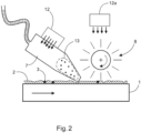
- Fig. 2 shows an embodiment of the invention in which the removal of parts of the layer is carried out mechanically.
- a flat workpiece 1 is shown, which is moved from left to right in the drawing.
- the workpiece 1 is coated with a liquid layer 2, which forms the surface of the workpiece 1 after it has completely hardened.
- a manipulation means 3 has been introduced into the liquid layer 2 at some points in order to displace the liquid layer 2.
- the workpiece 1 is moved, for example, by a transport device of a device according to the invention.
- a suction device 7 is arranged first, which is designed to suck up parts 13 of the layer 2 that have been released by means of negative pressure, in particular the released manipulation agent 3.
- the suction nozzle of the suction device 7 is aligned close to the surface of the layer 2.
- a brush 8, which is designed as a roller brush, is arranged downstream of the suction device 7. This extends perpendicular to the plane of the drawing, transverse to the direction of movement of the workpiece 1. In this embodiment, the roller brush is rotated in the opposite direction to the direction of movement of the workpiece 1.
- the suction device 7 also has a radiation source 12.
- This is designed to emit electromagnetic radiation, such as UV radiation, to harden the sucked-up parts 13 of the layer 2, whereby within the Suction device 7 hardens the parts 13 so that they do not run the risk of sticking within the suction device 7 and clogging it.
- electromagnetic radiation such as UV radiation
- parts 13 of the layer 2, in particular the manipulation means 3, are brushed out of the layer 2 and transported in the direction of the suction device 7. This takes up the detached parts 13 (outlined in dashed lines).
- a further radiation source 12a is shown, which is designed to emit electromagnetic radiation, in particular UV radiation, onto the brush 8 in order to harden and/or embrittle material adhering thereto from parts of the layer 2 in order to clean the brush 8, as described above.
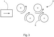
- Fig.3 shows an embodiment of brushes for mechanical removal of parts of the layer.
- a workpiece 1 and several brushes 8 are shown in a top view.
- the workpiece 1 is moved from left to right under the brushes 8.
- the brushes 8 are designed here as disc brushes that rotate about a respective axis in the rotation directions 9 shown. If the workpiece 1, on which a layer with or without a manipulation means (neither shown) is located, is moved under the brushes 8, parts of the layer, in particular the manipulation means, are mechanically removed by contact with the brushes 8 moving relative to the workpiece 1.
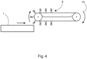
- Fig.4 shows a further embodiment of brushes for the mechanical removal of parts of the layer, in particular the manipulation agent.
- a workpiece 1 with a layer with or without a manipulation device (both not shown) and a brush belt are shown in side view.
- the workpiece 1 is moved from left to right.
- the brush belt is equipped with several brushes 8.
- the brush belt rotates cyclically in the direction of rotation 10 shown, so that the brushes 8, which are currently located on the underside of the brush belt, move from right to left against the movement of the workpiece 1.
- a further relative movement component is added, so that the force with which the bristles of the brushes 8 act on the layer or on the manipulation means is increased.
- Fig.5 shows a further embodiment of brushes for the mechanical removal of parts of the layer, in particular the manipulation agent.
- a workpiece 1 is shown in plan view, which is moved from left to right under a beam 11, which has brushes on its side facing the workpiece 1, which can come into contact with the workpiece 1 or with the layer and/or the manipulation means on it (neither shown).
- the beam 11 extends at least over the entire extent of the workpiece 1, i.e. from top to bottom in the drawing.
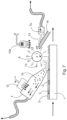
- Fig.7 shows a way to clean the contact element.
- a flat workpiece 1 is shown, which is moved from left to right in the drawing.
- the workpiece 1 is coated with a liquid layer 2, which forms the surface of the workpiece 1 after it has completely hardened.
- a manipulation means 3 has been introduced into the liquid layer 2 at some points in order to displace the liquid layer 2.
- the workpiece 1 is moved, for example, by a transport device of a device according to the invention.
- a suction device 7 is first arranged, which is designed to suck up parts 13 of the layer 2 that have been released by means of negative pressure, in particular the released manipulation agent 3.
- the suction nozzle of the suction device 7 is aligned close to the surface of the layer 2.
- a brush 8, which is designed as a roller brush, is arranged downstream of the suction device 7. This extends perpendicular to the plane of the drawing, transversely to the direction of movement of the workpiece 1. In this embodiment, the roller brush is rotated in the opposite direction to the direction of movement of the workpiece 1.
- the suction device 7 also has a radiation source 12. This is designed to emit electromagnetic radiation, such as UV radiation, to harden the sucked-up parts 13 of the layer 2, whereby the parts 13 harden within the suction device 7, so that there is no risk of them sticking within the suction device 7 and clogging it.
- a radiation source 12a which emits UV radiation onto the brush 8 and thus onto the parts 13 of the layer 2 adhering to the bristles of the brush 8, which can comprise material of the layer 2 as well as material of the manipulation means 3.
- the bristles of the brush 8 After being irradiated by the radiation source 12a, encounter a stripping edge 14.
- the stripping edge 14 extends to the bottom right in the drawing and has a surface that is shaped in such a way that parts 13 of the layer 2 that have been detached from the bristles are directed in the direction of a suction device 7a that is located on this surface.
- the suction device 7a is designed to pick up the detached parts 13 of the layer 2 and to suck them away using negative pressure.
- the cleaning function of brush 8 is as follows: Within a cycle, i.e. within one rotation of the brush 8, the bristles of the brush 8 first hit the surface of the layer 2, whereby parts 13 of the layer 2 are removed. Parts 13 that are detached and do not become stuck in the bristles of the brush 8 are conveyed by the brush in the direction of the suction device 7, which sucks them up using negative pressure. Parts 13 that have become stuck in the bristles of the brush 8 are irradiated by the radiation source 12a as the brush 8 continues to rotate, causing them to harden. The irradiation of the radiation source 12a can also be so strong that the parts 13 that have become stuck in the bristles of the brush 8 become brittle.
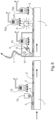
- Fig.8 shows a device in the form of a production line.
- Two workpieces 1 are shown which are moved one after the other in the direction of movement from left to right.
- a transport device (not shown) is provided for this purpose.
- the workpiece 1 has a liquid layer 2 on its surface.
- a manipulation means 3 is contained in and/or on the layer 2.
- the following elements are arranged one after the other from left to right in the direction of movement.
- a stationary contact element in the form of a brush 15 is arranged, which is designed to come into contact with the surface of the layer 2 in order to mechanically remove parts of the layer 2. This particularly ensures that the manipulation means 3 enclosed in the layer 2 is exposed.
- Downstream of the brush 15 is a radiation source 12 which is designed to emit UV radiation in the direction of the workpiece 1 or the layer 2 in order to at least partially harden the layer 2.
- the chamber 4 initially has a nozzle 6 in the direction of movement which emits a fluid flow at an angle to the surface of the layer 2 against the direction of movement of the workpiece 1.
- the angle is a maximum of 90° or less.
- the angle is preferably adjusted between 0° and 30°. This adjustment can be made, for example, depending on the material of the manipulation means removed and/or depending on the material of the layer 2 removed.
- the fluid flow has solid bodies as described above in order to remove parts 13 of the layer 2.
- the chamber also has a suction device 7 which is designed to suck up detached parts 13 of the layer 2.
- a radiation source 12 which is designed to irradiate the layer 2 with radiation in order to partially harden it, so that the viscosity of the layer 2 changes.
- the radiation can, for example, be UV radiation with a wavelength of 200 to 400 nm.
- the fluid flow is designed such that it extends over the entire width of the workpiece 1, i.e. in an extension direction of the workpiece 1 perpendicular to the plane of the drawing. In this way, it is ensured that all areas of the layer 2 are covered by the fluid flow.
- a liquid or a gaseous substance is used as the fluid.
- Water and/or air can also be used as the fluid.
- a contact element with a brush 8 in the form of a roller brush is arranged downstream of the chamber 4.
- the brush 8 is designed to mechanically remove parts of the layer 2.
- a radiation source 12a is arranged above the brush, which emits UV radiation onto the brush 8, for example.
- the cleaning of the brush 8 can be carried out essentially as described in Fig.7 take place.
- a further radiation source 12b is arranged downstream of the brush 8 in the direction of movement. This emits UV radiation, for example, onto the layer 2 and possibly desired manipulation agent 3 in order to carry out final hardening.
- Fig.9 shows an exemplary flow chart of the procedure.
- step S10 a liquid layer is applied to a workpiece, which then forms the surface of the workpiece when hardened. This can be done, for example, using a digital or analogue method.
- step S12 a manipulation agent is applied to and/or into a part of the liquid layer that is located on a workpiece. If step S12 is carried out before step S10, a manipulation agent can also be applied to the workpiece, with step S10 being carried out subsequently so that the manipulation agent is enclosed by the liquid layer.
- step S14 the layer is fixed to the workpiece using the manipulation device.
- the layer can be fixed.
- step S18 parts of the layer, which may also include material of the manipulation means, are removed. This is done as described above.
- the procedure can be further developed by swapping, omitting and/or repeating individual steps as well as by adding further steps.
- the invention is not limited to the embodiments shown here. Rather, other devices and/or methods can be obtained which also correspond to the invention by combining, exchanging or omitting individual features.
- the configuration can be Fig.7 into the production line Fig.8 be additionally integrated, or be provided instead of the chamber 4 and/or the brush 8 shown here.
- All nozzles 6 that are in the Figures 1 and 8th may be designed to deliver a fluid stream with or without solids as described above.
- the fluid stream may contain a gas and/or a liquid, specifically containing air and/or water.
- the radiation sources shown in all figures can be designed to emit other radiation, such as electron beams, as an alternative or in addition to electromagnetic radiation, in particular UV radiation.
- the type of radiation and/or the corresponding wavelength are selected depending on the material composition of the layer 2 and/or the manipulation means 3 and/or depending on the desired effect of the radiation on the layer 2 and/or the manipulation means 3. For example, a different wavelength and/or radiation can be used for complete curing than if only the viscosity of the layer 2 is to be changed in a preceding step, for example to prevent the depressions introduced by the manipulation means 3 from running.
- All of the embodiments of the invention shown here, which have at least one brush 8, can also be designed such that the at least one brush 8 is provided in a movable manner. This is to be understood as meaning that the at least one brush 8 can be actively moved by a predetermined movement pattern.
- a disc brush can be provided on a pivotable suspension.
Landscapes
- Engineering & Computer Science (AREA)
- Mechanical Engineering (AREA)
- Life Sciences & Earth Sciences (AREA)
- Toxicology (AREA)
- Health & Medical Sciences (AREA)
- Wood Science & Technology (AREA)
- Manufacturing & Machinery (AREA)
- Forests & Forestry (AREA)
- Physics & Mathematics (AREA)
- Plasma & Fusion (AREA)
- Application Of Or Painting With Fluid Materials (AREA)
- Turning (AREA)
- Grinding Of Cylindrical And Plane Surfaces (AREA)
- Chemically Coating (AREA)
- Physical Or Chemical Processes And Apparatus (AREA)
Description
Die vorliegende Erfindung bezieht sich auf ein Verfahren und eine Vorrichtung zum Bearbeiten einer Oberfläche eines Werkstückes, insbesondere zum Herstellen einer dekorativen Oberfläche.The present invention relates to a method and a device for machining a surface of a workpiece, in particular for producing a decorative surface.
Zur Herstellung von dekorativen Oberflächen im industriellen Maßstab, die beispielsweise die Nachbildung von Fliesen- oder Holzoberflächen zum Ziel haben, werden neben einer Schicht, die die spätere Oberfläche bildet, auch temporär weitere Manipulationsmittel aufgebracht, um die Oberfläche der Schicht zu manipulieren, so dass schließlich die dekorative Oberfläche erzeugt werden kann.To produce decorative surfaces on an industrial scale, for example to replicate tile or wood surfaces, in addition to a layer that forms the later surface, other manipulation agents are temporarily applied to manipulate the surface of the layer so that the decorative surface can finally be created.
Die
Die
Die
Bei den bekannten Verfahren muss nach der Durchführung des Verfahrens das temporär aufgebrachte Manipulationsmittel wieder entfernt werden. Hier besteht das Problem, dass das Manipulationsmittel, insbesondere wenn es mit der Schicht eine Verbindung eingegangen ist, zuverlässig und möglichst restlos entfernt werden muss. Es ist daher Aufgabe der vorliegenden Erfindung dieses Problem zu lösen.In the known methods, the temporarily applied manipulation agent must be removed again after the method has been carried out. The problem here is that the manipulation agent, especially if it has bonded to the layer, must be removed reliably and as completely as possible. It is therefore the object of the present invention to solve this problem.
Ein weiteres Ziel dieser vorliegenden Erfindung ist es, ein teilweises Entfernen der zuvor aufgebrachten Schicht zu ermöglichen, insbesondere an den Stellen, an denen das Manipulationsmittel aufgebracht wurde.A further object of this present invention is to enable partial removal of the previously applied layer, in particular at the locations where the manipulation agent has been applied.
Diese Aufgabe wird durch die Gegenstände der unabhängigen Ansprüche gelöst. Vorteilhafte Weiterbildungen sind Gegenstand der Unteransprüche.This problem is solved by the subject matter of the independent claims. Advantageous further developments are the subject matter of the subclaims.
Es wird somit ein Manipulationsmittel auf und/oder in eine zumindest teilweise flüssige Schicht aufgebracht, die sich auf einem Werkstück befindet.Thus, a manipulation agent is applied to and/or into an at least partially liquid layer located on a workpiece.
Das Aufbringen des Manipulationsmittels erfolgt dabei bevorzugt auf Teilflächen oder Teilbereiche der flüssigen Schicht und/oder des Werkstückes. Im weiteren Verlauf des Verfahrens werden Teile der Schicht entfernt. Die Entfernung erfolgt mechanisch und/oder berührungslos, insbesondere fluidisch.The manipulation agent is preferably applied to partial areas or partial regions of the liquid layer and/or the workpiece. In the further course of the process, parts of the layer are removed. The removal takes place mechanical and/or contactless, especially fluidic.
Erfindungsgemäß wird die Schicht, bevor das Entfernen von Teilen der Schicht durchgeführt wird, zusammen mit dem Manipulationsmittel zumindest teilweise ausgehärtet, so dass insbesondere die Viskosität der Schicht zunimmt.According to the invention, the layer is at least partially cured together with the manipulation agent before the removal of parts of the layer is carried out, so that in particular the viscosity of the layer increases.
Diese Verfahrensschritte können in einem Verfahren zur Herstellung einer dekorativen Oberfläche auf einem Werkstück vorgesehen sein. Zwischen der Durchführung des Entfernens von Teilen der Schicht und den zuvor durchgeführten Verfahrensschritten kann jedoch auch eine zeitliche Pause liegen, so dass es sich, insbesondere bei dem Entfernen von Teilen der Schicht, auch um ein eigenständiges Verfahren handeln kann.These process steps can be provided in a process for producing a decorative surface on a workpiece. However, there can also be a time pause between the removal of parts of the layer and the previously carried out process steps, so that it can also be an independent process, especially the removal of parts of the layer.
Vorzugsweise umfassen die Teile der Schicht, die entfernt werden, auch Teile des sich auf oder in der Schicht befindlichen Manipulationsmittels. In einer speziellen Ausführungsform handelt es sich dabei ausschließlich um das Manipulationsmittel. Wird das Manipulationsmittel von der Schicht entfernt, so kann dies teilweise erfolgen, so dass ein Rest des Manipulationsmittels auf und/oder in der Schicht zurückbleibt. Das Entfernen kann jedoch auch vollständig erfolgen, dass das Manipulationsmittel restlos entfernt wird.Preferably, the parts of the layer that are removed also include parts of the manipulation means located on or in the layer. In a specific embodiment, this is exclusively the manipulation means. If the manipulation means is removed from the layer, this can be done partially, so that a residue of the manipulation means remains on and/or in the layer. However, the removal can also be done completely, so that the manipulation means is completely removed.
Somit kann das Entfernen von Teilen der Schicht, bedeuten, dass Material der Schicht selbst entfernt wird. Alternativ kann auch ausschließlich das Manipulationsmittel von der Schicht entfernt werden. Es kann jedoch auch beides, also Material der Schicht selbst und Material des Manipulationsmittels entfernt werden.Thus, removing parts of the layer can mean that material from the layer itself is removed. Alternatively, only the manipulation device can be removed from the layer. However, both material from the layer itself and material from the manipulation device can also be removed.
Vorzugsweise erfolgt das mechanische Entfernen von Teilen der Schicht mit einer Entfernungsvorrichtung, die ein Kontaktelement aufweist, das mit der Oberfläche der Schicht in Kontakt steht, wobei sich die Oberfläche der Schicht und das Kontaktelement beim Entfernen relativ zueinander bewegen. Neben einer gegenläufigen Bewegung kann auch eine gleichläufige Bewegung oder eine anders ausgebildete Relativbewegung stattfinden.Preferably, the mechanical removal of parts of the layer is carried out with a removal device which has a contact element which is in contact with the surface of the layer, wherein the surface of the layer and the contact element move relative to each other during removal. In addition to a In addition to the opposite movement, a parallel movement or a different relative movement can also occur.
Vorzugsweise weist das Kontaktelement eine stehende und/oder eine bewegte Bürste und/oder ein Schleif- und/oder ein Hobelelement auf, wobei das Kontaktelement bewegt oder stehend gegenüber dem Werkstück vorgesehen ist. Vorzugsweise weist die Bürste zumindest als bewegte Bürste eine Tellerbürste und/oder eine Walzenbürste und/oder ein Bürstenband und/oder als stehende Bürste einen Balken mit Bürstenbesatz auf.The contact element preferably has a stationary and/or moving brush and/or a grinding and/or a planing element, wherein the contact element is provided in a moving or stationary manner relative to the workpiece. The brush preferably has at least as a moving brush a disk brush and/or a roller brush and/or a brush belt and/or as a stationary brush a bar with brush trim.
Das Schleif- und/oder Hobelelement ist vorzugsweise dazu ausgebildet, Teile der Schicht wieder abzutragen, um darin eingeschlossenes Manipulationsmittel freizulegen. Anschließend kann das Manipulationsmittel mittels des Schleif- und/oder Hobelelements oder mittels anderer hier beschriebener Verfahren entfernt werden. Das Schleifelement kann bevorzugt einen Bandschleifer umfassen.The grinding and/or planing element is preferably designed to remove parts of the layer again in order to expose manipulation means enclosed therein. The manipulation means can then be removed by means of the grinding and/or planing element or by means of other methods described here. The grinding element can preferably comprise a belt grinder.
Allgemein kann das Kontaktelement ein stehendes und/oder ein bewegtes Element aufweisen. Das Kontaktelement ist weiter bevorzugt als zyklisch arbeitendes Kontaktelement ausgebildet, das beispielsweise ein Schleifband oder eine Walzenbürste aufweist. Dadurch weist das Kontaktelement vorteilhafterweise Abschnitte auf, die während des Entfernens zyklisch nicht mit der Schicht in Kontakt stehen. Diese Abschnitte können in diesem Moment gereinigt werden, wie weiter unten beschrieben wird.In general, the contact element can have a stationary and/or a moving element. The contact element is further preferably designed as a cyclically operating contact element, which has, for example, a grinding belt or a roller brush. As a result, the contact element advantageously has sections that are not cyclically in contact with the layer during removal. These sections can be cleaned at this moment, as described further below.
Vorzugsweise weist das Kontaktelement, insbesondere die Bürste, Textil- und/oder Kunststofffasern, insbesondere Nylonfasern, und/oder Metall, insbesondere Stahl, Messing oder Kupfer auf. Darüber hinaus können auch Fasern zum Einsatz kommen, die ein Schleifmittel enthalten. Dabei handelt es sich vorzugsweise um Fasern mit Anderlon. Diese Fasern oder Materialien sind bevorzugt in den Borsten der Bürste enthalten. Somit sind insbesondere Ausbildungen der Bürste mit Metall- oder Kunststoffborsten möglich.The contact element, in particular the brush, preferably comprises textile and/or plastic fibers, in particular nylon fibers, and/or metal, in particular steel, brass or copper. In addition, fibers containing an abrasive can also be used. These are preferably fibers with Anderlon. These fibers or materials are preferably contained in the bristles of the brush. This means that brush designs with metal or plastic bristles are possible.
Die Bürste weist vorzugsweise Borsten auf, die einen Durchmesser von 0,05 bis 2 mm, vorzugsweise 0,1 bis 1,2 mm, weiter vorzugsweise 0,2 bis 0,7 mm, besonders bevorzugt 0,2 bis 0,3 mm, aufweisen.The brush preferably has bristles which have a diameter of 0.05 to 2 mm, preferably 0.1 to 1.2 mm, more preferably 0.2 to 0.7 mm, particularly preferably 0.2 to 0.3 mm.
Vorzugsweise umfasst das Entfernen von Teilen der Schicht eine Absaugung der Teile durch Unterdruck, vorzugsweise mittels einer Absaugvorrichtung.Preferably, the removal of parts of the layer comprises suctioning off the parts by means of negative pressure, preferably by means of a suction device.
Das Entfernen von Teilen der Schicht umfasst eine Erwärmung der Schicht und/oder des Manipulationsmittels. Die Erwärmung wird mittels Zuführung von Wärme zur zumindest teilweisen Verflüssigung der Teile der Schicht, insbesondere des Manipulationsmittels, durchgeführt. Die Wärmezuführung kann bevorzugt durch eine Heizung oder einen IR-Strahler erfolgen.The removal of parts of the layer includes heating the layer and/or the manipulation means. The heating is carried out by supplying heat to at least partially liquefy the parts of the layer, in particular the manipulation means. The heat can preferably be supplied by a heater or an IR radiator.
Vorzugsweise erfolgt eine gesteuerte und/oder geregelte Bewegung des Kontaktelementes. Dies kann beispielsweise die Positionierung des Kontaktelementes relativ zu der Schicht sein, oder auch eine Einstellung der Drehzahl bzw. der Umlaufgeschwindigkeit, der Tellerbürsten bzw. des Bürstenbandes.Preferably, the contact element is moved in a controlled and/or regulated manner. This can be, for example, the positioning of the contact element relative to the layer, or an adjustment of the rotational speed or the rotational speed of the disc brushes or the brush belt.
Während das Kontaktelement Teile der Schicht entfernt, kann ein Zusetzen des Kontaktelements durch das entfernte Material der Schicht und/oder des Manipulationsmittels eintreten. Bei einer Bürste bedeutet dies, dass sich das entfernte Material in den Borsten festsetzt. Auch ein Schleif- und/oder ein Hobelelement kann unter Umständen von dem Zusetzen betroffen sein. Daher kann ein weiterer Schritt vorgesehen sein, in dem eine Reinigung des Kontaktelements durchgeführt wird. Das gesamte Verfahren zur Reinigung des Kontaktelements, das nachfolgend beschrieben wird, kann auch unabhängig von dem in dieser Anmeldung beschriebenen Verfahren betrieben werden.While the contact element removes parts of the layer, the contact element can become clogged by the removed material of the layer and/or the manipulation means. In the case of a brush, this means that the removed material becomes stuck in the bristles. A grinding and/or planing element can also be affected by clogging under certain circumstances. A further step can therefore be provided in which the contact element is cleaned. The entire process for cleaning the contact element, which is described below, can also be carried out independently of the process described in this application.
Die Reinigung kann vorzugsweise durch mechanisches Abstreifen des Materials an einer Abstreifkante erfolgen, und/oder auch mittels Absaugung durch Unterdruck, beispielsweise durch die oben genannte oder eine weitere Absaugvorrichtung.Cleaning can preferably be carried out by mechanically stripping the material on a stripping edge and/or by suction using negative pressure, for example by the suction device mentioned above or another suction device.
Um die Viskosität des Materials und/oder des Manipulationsmittels zu verringern und so die Lösbarkeit von dem Kontaktelement zu verbessern, kann auch hier eine Zuführung von Wärme an das Kontaktelement vorgesehen sein. Die Wärmezuführung kann bevorzugt durch eine Heizung oder einen IR-Strahler erfolgen. Die Heizung kann beispielsweise in dem Kontaktelement vorgesehen sein.In order to reduce the viscosity of the material and/or the manipulation agent and thus improve the detachability of the contact element, a supply of heat to the contact element can also be provided here. The heat supply can preferably be carried out by a heater or an IR radiator. The heater can be provided in the contact element, for example.
Alternativ oder zusätzlich kann die Reinigung des Kontaktelementes umfassen, dass das Kontaktelement während des Entfernens des Manipulationsmittels und/oder von Teilen der zuvor aufgetragenen Schicht mit Strahlung, insbesondere elektromagnetischer Strahlung und/oder Elektronenstrahlung, bestrahlt wird. Dadurch wird insbesondere erreicht, dass das Material und/oder das Manipulationsmittel, das sich an dem Kontaktelement festgesetzt hatte, mindestens teilweise oder vollständig ausgehärtet wird, und dann in einer harten und spröden Form vorliegt. Vorzugsweise wird durch die Aushärtung des Materials erreicht, dass sich dieses leicht von dem Kontaktelement, insbesondere von den Borsten falls eine Bürste vorgesehen ist, löst. Durch mechanisches Abstreifen und/oder Absaugen kann dieses Material wieder von dem Kontaktelement entfernt werden.Alternatively or additionally, the cleaning of the contact element can include irradiating the contact element with radiation, in particular electromagnetic radiation and/or electron radiation, during the removal of the manipulation agent and/or parts of the previously applied layer. This in particular ensures that the material and/or the manipulation agent that had adhered to the contact element is at least partially or completely hardened and is then in a hard and brittle form. The hardening of the material preferably ensures that it can be easily detached from the contact element, in particular from the bristles if a brush is provided. This material can be removed from the contact element again by mechanical stripping and/or suction.
Zum mechanischen Abstreifen kann beispielsweise eine Abstreifkante vorgesehen sein, an der das zugesetzte Kontaktelement vorbeigeführt werden kann, wodurch das Manipulationsmittel und/oder der entfernte Teil der Schicht abgestreift werden können. Weist das Kontaktelement beispielsweise eine Bürste auf, so können hierzu die Borsten der Bürste mit der Abstreifkante in Kontakt treten.For mechanical stripping, a stripping edge can be provided, for example, along which the added contact element can be guided, whereby the manipulation means and/or the removed part of the layer can be stripped off. If the contact element has a brush, for example, the bristles of the brush can come into contact with the stripping edge.
Neben der Strahlungshärtung können auch weitere Härtungsmethoden eingesetzt werden, um das Material, das das Kontaktelement zugesetzt hat, auszuhärten. Allgemein können unterschiedliche Methoden eingesetzt werden, um insbesondere die Viskosität und/oder die Härte des Materials, das das Kontaktelement zusetzt, zu beeinflussen. Bei zyklisch arbeitenden Kontaktelementen ist es wichtig, dass das Entfernen von Teilen der Schicht sowie die Reinigung des Kontaktelements, also das Entfernen dieser Teile der Schicht von dem Kontaktelement, innerhalb eines Zyklus' ablaufen. Folglich muss auch die Beeinflussung der Viskosität, sofern sie im Verfahren durchgeführt wird, innerhalb dieses Zyklus' ablaufen. Da es sich bei dem Material, das das Kontaktelement zusetzt insbesondere um Material der Schicht und/oder des Manipulationsmittels handelt, kann daher grundsätzlich jedes Verfahren eingesetzt werden, das insbesondere ein Aushärten bzw. eine Änderung der Viskosität dieser Materialien bewirkt. Daher wird hierzu auf die in dieser Anmeldung beschriebenen Möglichkeiten verwiesen.In addition to radiation curing, other curing methods can also be used to harden the material that has clogged the contact element. In general, different methods can be used to influence the viscosity and/or hardness of the material that clogs the contact element. In the case of cyclically operating contact elements, it is important that the removal of parts of the layer and the cleaning of the contact element, i.e. the removal of these parts of the layer from the contact element, take place within a cycle. Consequently, the influencing of the viscosity, if it is carried out in the process, must also take place within this cycle. Since the material that clogs the contact element is in particular material of the layer and/or the manipulation means, in principle any process can be used that in particular involves hardening or a change in the viscosity of these materials. Therefore, reference is made to the options described in this application.
In einer bevorzugten Ausführungsform weist das Material und/oder das Manipulationsmittel einen Anteil von mehr als 70% von Acrylaten, die sich durch Bestrahlung mit elektromagnetischer Strahlung über die Bildung von chemischen Bindungen vernetzen, und so die Viskosität und damit auch die Klebrigkeit des Materials und/oder des Manipulationsmittels verringern, und die Sprödigkeit erhöhen. Daher ist die oben beschriebene Ausführungsform der Reinigung des Kontaktelements gut geeignet, um einen dauerhaften und wenig störanfälligen Betrieb einer nach dem erfindungsgemäßen Verfahren produzierenden industriellen Anlage zu gewährleisten.In a preferred embodiment, the material and/or the manipulation agent has a proportion of more than 70% of acrylates, which crosslink through the formation of chemical bonds when exposed to electromagnetic radiation, thus reducing the viscosity and thus also the stickiness of the material and/or the manipulation agent and increasing the brittleness. Therefore, the embodiment of cleaning the contact element described above is well suited to ensuring long-term and less susceptible to failure operation of an industrial plant producing according to the method according to the invention.
In anderen Ausführungsformen kann das Material und/oder das Manipulationsmittel auch andere Bestandteile aufweisen oder daraus ausgebildet sein, wie beispielsweise eine wässrige Mischung mit Bindemitteln, Pigmenten und anderen Additiven.In other embodiments, the material and/or the manipulation means may also comprise or be formed from other components, such as an aqueous mixture with binders, pigments and other additives.
Vorzugsweise umfasst das Entfernen von Teilen der Schicht ein Beströmen der Oberfläche der Schicht und/oder des Manipulationsmittels mit einem Fluidstrom, insbesondere mit einem Luftstrom. Auf diese Weise kann insbesondere das Manipulationsmittel berührungslos entfernt werden, was vorteilhafterweise schonend für die Oberfläche der Schicht ist. So können auch Werkstücke verarbeitet werden, die Elemente aufweisen, die durch nicht berührungslose Verfahren, beispielsweise durch den Kontakt mit einer oben beschriebenen Bürste, beschädigt werden können. Zur Verdeutlichung ist in
Des Weiteren kann das Verfahren vorzugsweise auch für Oberflächen außerhalb des Fußbodenbelages, z.B. für Möbel-, Wand-, Deckenoberflächen oder auch für Außenfassadenelemente oder weitere Anwendungen genutzt werden.Furthermore, the process can preferably also be used for surfaces outside of the floor covering, e.g. for furniture, wall, ceiling surfaces or also for external facade elements or other applications.
Vorzugsweise trifft der Fluidstrom entsprechend ausgeformt auf die Oberfläche der Schicht und/oder des Manipulationsmittels, so dass er sich über die gesamte Breite der Schicht erstreckt. Die Länge der Erstreckung der Auftrefffläche des Fluidstroms in Bewegungsrichtung des Werkstückes liegt vorzugsweise bei 1% bis 20%, besonders bevorzugt bei 5% bis 15%, insbesondere bei 10% bis 12%, der Länge der Erstreckung des Fluidstroms quer zur Bewegungsrichtung. Somit wird bevorzugt ein möglichst dünner Fluidstrom insbesondere im Sinne einer "Luftklinge" bzw. eines "Luftmessers" verwendet. Alternativ kann als Fluidstrom auch ein Flüssigkeitsstrom, insbesondere enthaltend Wasser, verwendet werden.Preferably, the fluid flow impinges on the surface of the layer and/or the manipulation means in a correspondingly shaped manner so that it extends over the entire width of the layer. The length of the impact surface of the fluid flow in the direction of movement of the workpiece is preferably 1% to 20%, particularly preferably 5% to 15%, in particular 10% to 12%, of the length of the fluid flow transverse to the direction of movement. Thus, a fluid flow that is as thin as possible is preferably used, in particular in the sense of an "air blade" or an "air knife". Alternatively, a liquid flow, in particular containing water, can also be used as the fluid flow.
Vorzugsweise trifft der Fluidstrom unter einem Winkel auf die Schicht und/oder auf das Manipulationsmittels, der geringer als 45°, vorzugsweise geringer als 30°, besonders bevorzugt geringer als 15°, ist. Insbesondere bei lediglich auf die Oberfläche der Schicht aufgetragenem Manipulationsmittel ist eine flache Anströmung sinnvoll um eine Ablösung von der Schicht zu erreichen, sollte beispielsweise nur das Manipulationsmittel werden sollen. Je nach Situation kann jedoch auch eine steilere Anstellung des Fluidstroms sinnvoll sein, um beispielsweise Manipulationsmittel, das in Vertiefungen der Schicht enthalten ist, auszublasen. Bevorzugt wird der Winkel während der Durchführung des Verfahrens verändert, besonders bevorzugt periodisch verändert. Die Veränderung kann vorzugsweise auch in Abhängigkeit der aktuell erfassten Menge des entfernten Manipulationsmittels erfolgen. Diese Menge wird vorzugsweise durch eine Erfassungseinrichtung erfasst, die beispielsweise das Gewicht des Manipulationsmittels erfasst, das entfernt wurde.Preferably, the fluid flow hits the layer and/or the manipulation agent at an angle that is less than 45°, preferably less than 30°, particularly preferably less than 15°. Particularly when the manipulation agent is only applied to the surface of the layer, a flat flow is useful in order to achieve detachment from the layer, for example if only the manipulation agent is to be removed. Depending on the situation, however, a steeper angle of the fluid flow may also be useful, for example to blow out manipulation agent contained in depressions in the layer. Preferably, the angle is changed while the method is being carried out, particularly preferably changed periodically. The change can preferably also be made depending on the currently detected amount of the manipulation agent removed. This amount is preferably detected by a detection device that, for example, detects the weight of the manipulation agent that was removed.
Alternativ oder zusätzlich kann der Fluidstrom auch durch sogenannte Rotationsdüsen auf die Oberfläche der Schicht auftreffen. Dabei rotieren die Rotationsdüsen, welche den Fluidstrom auf die Oberfläche leiten, um eine mittlere Achse, bei einem gesamten Durchmesser der rotierenden Düsen von vorzugsweise 2-120 mm, besonders bevorzugt 5-50 mm. Dadurch wird ein zeitlich variabler Fluidstrom auf die Oberfläche gelenkt.Alternatively or additionally, the fluid flow can also hit the surface of the layer through so-called rotating nozzles. The rotating nozzles, which direct the fluid flow onto the surface, rotate around a central axis, with a total diameter of the rotating nozzles of preferably 2-120 mm, particularly preferably 5-50 mm. This directs a temporally variable fluid flow onto the surface.
Bevorzugt enthält der Fluidstrom ferner Festkörper, die die Entfernung von Teilen der Schicht verbessern. Beispielsweise kann hier Sand oder eine vergleichbare Substanz enthalten sein, die zusätzlich neben dem Fluidstrom auf die Oberfläche der Schicht und/oder des Manipulationsmittels wirkt. Der Fluidstrom kann insbesondere dadurch auch dazu verwendet werden, um neben dem Manipulationsmittel auch Material der Schicht abzutragen.Preferably, the fluid flow also contains solids that improve the removal of parts of the layer. For example, this can contain sand or a similar substance that acts on the surface of the layer and/or the manipulation means in addition to the fluid flow. The fluid flow can therefore also be used to remove material from the layer in addition to the manipulation means.
Die Festkörper weisen vorzugsweise einen Durchmesser von 0,0001 bis 1 mm, bevorzugt 0,001 bis 0,5 mm, besonders bevorzugt 0,005 bis 0,3 mm auf.The solid bodies preferably have a diameter of 0.0001 to 1 mm, preferably 0.001 to 0.5 mm, particularly preferably 0.005 to 0.3 mm.
Alternativ oder zusätzlich sind die Festkörper dazu ausgebildet, sich nach dem Auftreffen auf die Schicht und/oder auf das Manipulationsmittel zu verflüssigen oder zu verdampfen. Dies kann beispielsweise dadurch erreicht werden, dass die Festkörper die Eigenschaft aufweisen, bei der Umgebungstemperatur, der das Werkstück mit der Schicht ausgesetzt ist, zu verdampfen. Beispielsweise kann dies durch Festkörper aus Trockeneis erreicht werden. Diese können insbesondere durch einen Trockeneis-Strahler auf die Oberfläche der Schicht und/oder des Manipulationsmittels aufgebracht werden. So wird vorteilhafterweise erreicht, dass die Festkörper nicht auf und/oder in der Schicht zurückbleiben. Somit kann auf eine anschließende Entfernung der Festkörper von der Schicht verzichtet werden.Alternatively or additionally, the solid bodies are designed to liquefy or evaporate after hitting the layer and/or the manipulation means. This can be achieved, for example, by the solid bodies having the property of evaporating at the ambient temperature to which the workpiece with the layer is exposed. For example, this can be achieved using solid bodies made of dry ice. These can be applied to the surface of the layer and/or the manipulation means in particular using a dry ice blaster. This advantageously ensures that the solid bodies do not remain on and/or in the layer. This means that subsequent removal of the solid bodies from the layer is not necessary.
Alternativ oder zusätzlich kann vorgesehen sein, dass die Festkörper während der Erzeugung des Fluidstroms mit einer Flüssigkeit, insbesondere mit Wasser, beaufschlagt werden. Dadurch wird erreicht, dass eine Erhöhung der Masse der Festkörper erfolgt, so dass die Wirkung auf die Oberfläche der Schicht und/oder des Manipulationsmittels erhöht wird. Die Beaufschlagung kann beispielsweise dadurch erfolgen, dass die Festkörper mit dem Fluidstrom durch einen Nebel der Flüssigkeit bewegt werden. Dadurch wirken die Festkörper als Kondensationskeime an denen Bestandteile des Nebels anhaften, wodurch schließlich die Beaufschlagung des Festkörpers mit der Flüssigkeit erfolgt.Alternatively or additionally, it can be provided that the solid bodies are exposed to a liquid, in particular water, during the generation of the fluid flow. This results in an increase in the mass of the solid bodies, so that the effect on the surface of the layer and/or the manipulation means is increased. The exposure can be achieved, for example, by This can be done by moving the solids with the fluid flow through a mist of liquid. The solids then act as condensation nuclei to which components of the mist adhere, which ultimately causes the solid to be exposed to the liquid.
Die Festkörper können speziell Sandkörner, Trockeneis (festes CO2), Wassereis (gefrorenes Wasser), Natriumbicarbonat, oder Mischungen aus diesen genannten Festkörpern aufweisen.The solids can specifically include grains of sand, dry ice (solid CO2), water ice (frozen water), sodium bicarbonate, or mixtures of these solids.
Vorzugsweise weist das Verfahren ferner zumindest einen der folgenden Schritte auf:
- Aufbringen einer flüssigen Schicht zumindest auf einen Teil einer Oberfläche des Werkstückes und/oder auf ein auf die Oberfläche des Werkstückes aufgebrachtes Manipulationsmittel;
- Aushärten der Schicht und/oder des Manipulationsmittels zumindest bis zur teilweisen Aushärtung.
- Applying a liquid layer to at least part of a surface of the workpiece and/or to a manipulation agent applied to the surface of the workpiece;
- Curing of the layer and/or the manipulation agent at least until partial curing.
In einer speziellen Ausführungsform liegt ein Verfahren vor, das diesen Ablauf aufweist:
- Aufbringen einer flüssigen Schicht zumindest auf einen Teil einer Oberfläche des Werkstückes und/oder auf ein auf die Oberfläche des Werkstückes aufgebrachtes Manipulationsmittel;
- Aufbringen des Manipulationsmittels zumindest auf einen Teil der flüssigen Schicht und/oder in die flüssige Schicht und/oder zumindest auf einen Teil des Werkstückes;
- Aushärten der Schicht und/oder des Manipulationsmittels zumindest bis zur teilweisen Aushärtung;
- Entfernen des Manipulationsmittels, wie oben beschrieben.
- Applying a liquid layer to at least part of a surface of the workpiece and/or to a manipulation agent applied to the surface of the workpiece;
- Applying the manipulation agent to at least a part of the liquid layer and/or into the liquid layer and/or at least to a part of the workpiece;
- Curing the layer and/or the manipulation agent at least until partially cured;
- Remove the tampering device as described above.
Die Schicht und/oder das Manipulationsmittel sind vorzugsweise mittels elektromagnetischer Strahlung polymerisierbar ausgebildet.The layer and/or the manipulation means are preferably designed to be polymerizable by means of electromagnetic radiation.
In einer weiteren speziellen Ausführungsform liegt ein Verfahren vor, das folgenden Ablauf aufweist:
- Aufbringen einer flüssigen Schicht zumindest auf einen Teil einer Oberfläche des Werkstückes;
- Aufbringen des Manipulationsmittels zumindest auf einen Teil der flüssigen Schicht und/oder in die flüssige Schicht;
- Aushärten der Schicht und/oder des Manipulationsmittels zumindest bis zur teilweisen Aushärtung;
- Entfernen von Teilen der Schicht, wie oben beschrieben.
- Applying a liquid layer to at least part of a surface of the workpiece;
- Applying the manipulation agent to at least a part of the liquid layer and/or into the liquid layer;
- Curing the layer and/or the manipulation agent at least until partially cured;
- Remove parts of the layer as described above.
Bei dieser zuletzt genannten Ausführungsform kann das aufgebrachte Manipulationsmittel auch vollständig oder teilweise mit dem letzten Schritt (Entfernen von Teilen der Schicht) gemeinsam mit entfernt werden.In this last-mentioned embodiment, the applied manipulation agent can also be completely or partially removed together with the last step (removal of parts of the layer).
Bei jeder denkbaren Ausführungsform des Verfahrens, insbesondere bei den beiden eben beschriebenen speziellen Ausführungsformen, können weitere Verfahrensschritte vorgesehen sein, die sowohl vor, zwischen als auch nach den bisher beschriebenen Verfahrensschritten vorgesehen sein können. Zudem können auch einzelne Verfahrensschritte wiederholt werden.In every conceivable embodiment of the method, in particular in the two specific embodiments just described, further method steps can be provided, which can be provided before, between or after the method steps described so far. In addition, individual method steps can also be repeated.
Vorzugsweise weist das Manipulationsmittel Wasser auf. Das Manipulationsmittel besteht in einer speziellen Ausführungsform ausschließlich aus Wasser.The manipulation agent preferably comprises water. In a special embodiment, the manipulation agent consists exclusively of water.
Bevorzugt weist die Schicht und/oder das Manipulationsmittel acrylathaltiges Material auf.Preferably, the layer and/or the manipulation means comprises acrylate-containing material.
Das Werkstück wird vorzugsweise bei der Durchführung des Verfahrens in einer Bewegungsrichtung bewegt und so nacheinander Elementen einer Vorrichtung zugeführt, die zur Ausführung der einzelnen Verfahrensschritte ausgebildet sind. Alternativ oder zusätzlich kann auch vorgesehen sein, dass sich die Elemente der Vorrichtung im Verhältnis zu dem Werkstück bewegen.When carrying out the method, the workpiece is preferably moved in one direction of movement and is thus fed successively to elements of a device which are designed to carry out the individual method steps. Alternatively or additionally, it can also be provided that the elements of the device move in relation to the workpiece.
Das Verfahren kann beispielsweise so durchgeführt werden, dass die Schicht in flüssiger Form auf die Oberfläche des Werkstückes aufgebracht wird. Anschließend wird das Manipulationsmittel auf und/oder in die Schicht aufgebracht. Das Verfahren kann jedoch auch so ausgebildet sein, dass zunächst das Manipulationsmittel auf die Oberfläche des Werkstückes aufgebracht wird. Anschließend erfolgt dann ein Aufbringen der Schicht. Das Manipulationsmittel fungiert hier vorzugsweise als Platzhalter, so dass Bereiche der Oberfläche des Werkstückes nicht mit der Schicht in Kontakt kommen. Wird das Manipulationsmittel entfernt, nachdem die Schicht ausgehärtet wurde, verbleiben diese Stellen als Vertiefungen bzw. Aussparungen in der Schicht. Natürlich sind auch Ausführungsformen denkbar, bei denen sowohl ein Aufbringen des Manipulationsmittels vor als auch nach dem Auftrag der Schicht erfolgt. Auch ist ein mehrmaliges Wiederholen des Aufbringens der Schicht und/oder des Manipulationsmittels möglich. Wird das Manipulationsmittel als Platzhalter eingesetzt, so wird das Manipulationsmittel bevorzugt vor Aufbringen der flüssigen Schicht ausgehärtet.The process can be carried out, for example, by applying the layer in liquid form to the surface of the workpiece. The manipulation agent is then applied to and/or into the layer. The process can, however, also be designed in such a way that the manipulation agent is first applied to the surface of the workpiece. The layer is then applied. The manipulation agent preferably functions as a placeholder so that areas of the surface of the workpiece do not come into contact with the layer. If the manipulation agent is removed after the layer has hardened, these areas remain as depressions or recesses in the layer. Of course, embodiments are also conceivable in which the manipulation agent is applied both before and after the layer is applied. It is also possible to repeat the application of the layer and/or the manipulation agent several times. If the manipulation agent is used as a placeholder, the manipulation agent is preferably hardened before the liquid layer is applied.
Vor dem Ausbringen des Manipulationsmittels kann eine Trocknung oder Aushärtung der flüssigen Schicht, vorzugsweise mit elektromagnetischer Strahlung mit einer Wellenlänge von 200 bis 400 nm, erfolgen, um insbesondere die Viskosität der flüssigen Schicht zu beeinflussen.Before the manipulation agent is applied, the liquid layer can be dried or cured, preferably with electromagnetic radiation with a wavelength of 200 to 400 nm, in order to influence in particular the viscosity of the liquid layer.
Vorzugsweise wird nach dem Aufbringen der flüssigen Schicht das Manipulationsmittel auf Teile der flüssigen Schicht aufgebracht.Preferably, after the liquid layer has been applied, the manipulation agent is applied to parts of the liquid layer.
Vorzugsweise werden, insbesondere zur Aushärtung, das Manipulationsmittel und die zumindest teilweise flüssige Schicht mit elektromagnetischer Strahlung, bevorzugt mit einer Wellenlänge von 180 bis 400 nm, bestrahlt.Preferably, in particular for curing, the manipulation agent and the at least partially liquid layer are irradiated with electromagnetic radiation, preferably with a wavelength of 180 to 400 nm.
Das Aushärten kann darüber hinaus ebenso mehrmals durchgeführt werden. Es kann beispielsweise ein erstes Aushärten der Schicht zumindest bis zur teilweisen Aushärtung durchgeführt werden, bevor das Manipulationsmittel aufgebracht wird. Auf diese Weise kann gezielt eine gewünschte Viskosität der Schicht eingestellt werden, so dass beispielsweise eine Struktur, die durch den Auftrag des Manipulationsmittels entsteht, für eine gewünschte Zeit Bestand hat, bevor die Struktur wieder zerläuft.Curing can also be carried out several times. For example, the layer can be cured for the first time until it is at least partially cured before the manipulation agent is applied. In this way, the desired viscosity of the layer can be set so that, for example, a structure created by applying the manipulation agent lasts for a desired time before the structure runs away again.
Vorzugsweise beinhaltet das Aushärten eine Bestrahlung der Schicht und/oder des Manipulationsmittels mit elektromagnetischer Strahlung, vorzugsweise mit UV-Strahlung, und/oder eine Bestrahlung mit Elektronenstrahlung.Preferably, the curing includes irradiation of the layer and/or the manipulation means with electromagnetic radiation, preferably with UV radiation, and/or irradiation with electron radiation.
Das Aushärten kann bevorzugt zeitgleich mit dem Entfernen von Teilen der Schicht erfolgen. Beispielsweise kann die Stelle der Schicht, die gerade mit dem Kontaktelement in Kontakt steht gleichzeitig mit UV-Strahlung bestrahlt werden, die die Aushärtung bewirkt. Gleiches gilt für alle mechanischen oder berührungslosen Entfernungsmöglichkeiten, wie oben beschrieben.Curing can preferably take place at the same time as removing parts of the layer. For example, the part of the layer that is currently in contact with the contact element can be irradiated with UV radiation at the same time, which causes curing. The same applies to all mechanical or contactless removal options, as described above.
Das Manipulationsmittel, das Teile der Schicht abdeckt, kann bewirken, dass der abgedeckte Teil der Schicht bei der Aushärtung nicht in demselben Maße aushärtet wie freiliegende Teile. Dabei kann es sich insbesondere um die hier beschriebenen Methoden zur Aushärtung handeln. Nach dem Entfernen von Teilen der Schicht wird dann bevorzugt eine abschließende Härtung der verbleibenden Schicht und/oder des verbleibenden Manipulationsmittels durchgeführt.The manipulation agent that covers parts of the layer can cause the covered part of the layer not to harden to the same extent as exposed parts during curing. This can in particular be the methods of curing described here. After removing parts of the layer, a final curing of the remaining layer and/or the remaining manipulation agent is then preferably carried out.
Alternativ oder zusätzlich beinhaltet das Aushärten aktive und/oder passive Trocknung. Unter aktiver Trocknung wird im Weiteren jede Art von Trocknung verstanden, bei der die flüssige Schicht durch Schaffung von speziellen Bedingungen getrocknet wird. So kann die flüssige Schicht und/oder das Manipulationsmittel insbesondere mittels Anströmung mit einem Fluid, insbesondere mit Luft, und/oder durch Zuführung von Wärme, insbesondere mittels IR-Strahlung oder durch Verwendung einer Heizung, getrocknet werden. Passive Trocknung ist hingegen vorzugsweise dadurch gekennzeichnet, dass die flüssige Schicht und/oder das Manipulationsmittel alleine und ohne weitere Bearbeitung aushärtet. Dies kann beispielsweise durch Transport des Werkstücks auf einem freien Streckenabschnitt eines Bandtransports erfolgen, und/oder durch Ablegen des Werkstücks.Alternatively or additionally, curing includes active and/or passive drying. Active drying is understood to mean any type of drying in which the liquid layer is dried by creating special conditions. The liquid layer and/or the manipulation means can be dried in particular by means of a flow of a fluid, in particular air, and/or by supplying heat, in particular by means of IR radiation or by using a heater. Passive drying, on the other hand, is preferably characterized by the liquid layer and/or the manipulation means curing on its own and without further processing. This can be done, for example, by transporting the workpiece on a free section of a belt conveyor and/or by laying the workpiece down.
Vorzugsweise erfolgt das Aushärten mittels Reaktionsaushärtung durch beispielsweise ein Zwei-Komponentensystem, welches durch chemische Reaktion zwischen den Komponenten der Schicht und/oder des Manipulationsmittels innerhalb von weniger als 30 Minuten, bevorzugt weniger als 5 Minuten aushärtet.Preferably, the curing is carried out by means of reaction curing, for example by a two-component system, which cures by chemical reaction between the components of the layer and/or the manipulation agent within less than 30 minutes, preferably less than 5 minutes.
Vorzugsweise wird die Schicht nach dem Aufbringen des Manipulationsmittels dergestalt ausgehärtet, dass sich die Viskosität der Stellen der Schicht an denen das Manipulationsmittel aufgebracht war von der Viskosität der Stellen an denen das Manipulationsmittel nicht aufgebracht war unterscheidet. Der Unterschied entspricht vorzugsweise mindestens einem Faktor 1,5, besonders bevorzugt mindestens einem Faktor 2. Vorzugsweise ist die Viskosität dabei an Stellen an denen das Manipulationsmittel aufgebracht war geringer als an Stellen an denen das Manipulationsmittel nicht aufgebracht war. Dies ist im Falle von Strahlungshärtung dadurch zu begründen, dass die Schicht unterhalb des Manipulationsmittels zumindest teilweise von der Strahlung abgeschirmt wurde, wodurch die Schicht hier einem geringeren Maß an Strahlung ausgesetzt war und somit weniger stark aushärtete.Preferably, after the manipulation agent has been applied, the layer is cured in such a way that the viscosity of the areas of the layer where the manipulation agent was applied differs from the viscosity of the areas where the manipulation agent was not applied. The difference preferably corresponds to at least a factor of 1.5, particularly preferably at least a factor of 2. Preferably, the viscosity is lower at areas where the manipulation agent was applied than at areas where the manipulation agent was not applied. In the case of radiation curing, this is due to the fact that the layer beneath the manipulation agent was at least partially shielded from the radiation, whereby the layer was exposed to a lower level of radiation here and thus cured less strongly.
Vorzugsweise wird das Aushärten der Schicht nach dem Entfernen von Teilen der Schicht bis zur Endhärtung der Schicht durchgeführt.Preferably, the curing of the layer is carried out after removing parts of the layer until the layer is finally cured.
Vorzugsweise erfolgt das Aufbringen der flüssigen Schicht auf das Werkstück mit einem digitalen und/oder analogen Verfahren. Besonders bevorzugt erfolgt der Auftrag der flüssigen Schicht auf die gesamte Oberfläche des Werkstückes. Bei einem analogen Verfahren kann das Aufbringen mittels einer Auftragswalze oder einer Gießmaschine, die einen flüssigen Vorhang aus dem Material der Schicht erzeugt, durch den das Werkstück bewegt wird, erfolgen. Eine Auftragswalze und eine Gießmaschine haben den Vorteil, dass die Schicht mit relativ wenig Aufwand auf eine möglichst breite Fläche des Werkstückes aufgebracht werden kann. Bei einem digitalen Verfahren erfolgt das Aufbringen mittels digitaler Drucktechnik, beispielsweise mit einem Digitaldruckkopf oder Digitaldüsenbalken. Dadurch kann die Schicht auch nur auf Teilbereiche des Werkstückes aufgebracht werden.The liquid layer is preferably applied to the workpiece using a digital and/or analogue method. The liquid layer is particularly preferably applied to the entire surface of the workpiece. In an analogue method, the application can be carried out using an application roller or a casting machine that creates a liquid curtain made of the material of the layer through which the workpiece is moved. An application roller and a casting machine have the advantage that the layer can be applied to as wide an area of the workpiece as possible with relatively little effort. In a digital method, the application is carried out using digital printing technology. for example with a digital print head or digital nozzle bar. This means that the layer can also be applied to only parts of the workpiece.
Vorzugsweise erfolgt das Aufbringen des Manipulationsmittels auf das Werkstück und/oder auf die flüssige Schicht mit einem digitalen Verfahren. Dafür wird digitale Drucktechnik, beispielsweise mit einem Digitaldruckkopf oder Digitaldüsenbalken, eingesetzt. Dadurch kann das aufzubringende Manipulationsmittel besonders sparsam und präzise eingesetzt werden. Es ist jedoch auch analoge Technik, wie beispielsweise eine Gießvorrichtung denkbar.The manipulation agent is preferably applied to the workpiece and/or to the liquid layer using a digital process. Digital printing technology is used for this, for example with a digital print head or digital nozzle bar. This allows the manipulation agent to be applied to be used particularly economically and precisely. However, analog technology, such as a pouring device, is also conceivable.
Vorzugsweise umfasst das Aufbringen des Manipulationsmittels ein Aufbringen des Manipulationsmittels in Form von Tröpfchen und/oder in Form von feinen Tröpfchen. Das Aufbringen des Manipulationsmittels in Form von Tröpfchen auf die Schicht erfolgt vorzugsweise derart, dass die Tröpfchengeschwindigkeit und/oder das Tröpfchenvolumen so gesteuert werden, dass durch die Tröpfchen Vertiefungen in die Schicht eingebracht werden, wobei die Vertiefungen vorzugsweise eine Tiefe von vorzugsweise 2 µm bis 100 µm, besonders bevorzugt von 3 µm bis 50 µm, aufweisen.The application of the manipulation agent preferably comprises applying the manipulation agent in the form of droplets and/or in the form of fine droplets. The application of the manipulation agent in the form of droplets to the layer is preferably carried out in such a way that the droplet speed and/or the droplet volume are controlled such that depressions are introduced into the layer by the droplets, the depressions preferably having a depth of preferably 2 µm to 100 µm, particularly preferably 3 µm to 50 µm.
Die Abgabe der feinen Tröpfchen wird vorzugsweise derart gesteuert, dass ihr Impuls beim Auftreffen auf die Oberfläche der flüssigen Schicht nicht ausreicht, um die Oberflächenspannung und/oder die Viskositätskräfte der flüssigen Schicht zumindest teilweise zu überwinden, so dass die feinen Tröpfchen vorzugsweise auf der Oberfläche der flüssigen Schicht zum Liegen kommen. Besonders bevorzugt wird das Manipulationsmittel in Form von feinen Tröpfchen als Nebel auf die Oberfläche der Schicht aufgebracht, so dass dieser insbesondere geschlossene Bereiche ausbildet, die die Oberfläche der Schicht bedecken.The release of the fine droplets is preferably controlled in such a way that their momentum when they hit the surface of the liquid layer is not sufficient to at least partially overcome the surface tension and/or the viscosity forces of the liquid layer, so that the fine droplets preferably come to rest on the surface of the liquid layer. The manipulation agent is particularly preferably applied to the surface of the layer in the form of fine droplets as a mist, so that it forms closed areas in particular that cover the surface of the layer.
Die feinen Tröpfchen weisen dabei insbesondere ein Volumen von 0,1 pl bis 1 pl, vorzugsweise von 0,3 pl bis 0,8 pl, besonders bevorzugt von 0,5 bis 0,6 pl auf.The fine droplets have in particular a volume of 0.1 pl to 1 pl, preferably of 0.3 pl to 0.8 pl, particularly preferably of 0.5 to 0.6 pl.
Die Tröpfchen weisen dabei insbesondere ein Volumen von 1 pl bis 80 pl, vorzugsweise von 3 pl bis 12 pl, besonders bevorzugt von 5 pl bis 10 pl auf.The droplets have in particular a volume of 1 pl to 80 pl, preferably 3 pl to 12 pl, particularly preferably 5 pl to 10 pl.
Die Geschwindigkeit der Tröpfchen und/oder der feinen Tröpfchen beträgt insbesondere zwischen 0,5 m/s und 12 m/s, vorzugsweise zwischen 3 m/s und 7 m/s, besonders bevorzugt zwischen 5 m/s und 6 m/s.The speed of the droplets and/or the fine droplets is in particular between 0.5 m/s and 12 m/s, preferably between 3 m/s and 7 m/s, particularly preferably between 5 m/s and 6 m/s.
Während dem Aufbringen des Manipulationsmittels kann die Geschwindigkeit und/oder das Volumen der Tröpfchen und/oder der feinen Tröpfchen variiert werden.During application of the manipulation agent, the speed and/or volume of the droplets and/or the fine droplets can be varied.
Die Abgabe der Tröpfchen wird vorzugsweise derart gesteuert, dass ihr Impuls beim Auftreffen auf die Oberfläche der flüssigen Schicht ausreicht, um die Oberflächenspannung und/oder die Viskositätskräfte der flüssigen Schicht zumindest teilweise zu überwinden, so dass durch die Tröpfchen eine Verdrängung der flüssigen Schicht erfolgt, wodurch in der flüssigen Schicht Vertiefungen und insbesondere eine Struktur von 10 bis 50 µm Höhenunterschied eingebracht werden kann.The release of the droplets is preferably controlled in such a way that their momentum when they hit the surface of the liquid layer is sufficient to at least partially overcome the surface tension and/or the viscosity forces of the liquid layer, so that the droplets displace the liquid layer, whereby depressions and in particular a structure with a height difference of 10 to 50 µm can be introduced into the liquid layer.
Vorzugsweise ist das Manipulationsmittel dazu ausgebildet, einfallende elektromagnetische Strahlung zumindest teilweise zu absorbieren, wobei vorzugsweise mindestens 10%, besonders bevorzugt mindestens 30%, insbesondere mindestens 50% der einfallenden elektromagnetischen Strahlung absorbiert werden. Auf diese Weise ist es möglich die Oberfläche der Schicht zumindest teilweise von elektromagnetischer Strahlung abzuschirmen, so dass, insbesondere beim Aushärten der flüssigen Schicht, die elektromagnetische Strahlung unterschiedlich stark auf die Oberfläche der Schicht wirkt. An den Stellen der Schicht, die mit dem Manipulationsmittel bedeckt sind, wirkt die elektromagnetische Strahlung schwächer im Vergleich zu freiliegenden Stellen. So kann, wenn beispielsweise eine Wellenlänge von kleiner 300 nm, vorzugsweise kleiner 250 nm, besonders bevorzugt kleiner 200 nm verwendet wird, eine Mikrofaltung an der Oberfläche der Schicht erzeugt werden, die an den Stellen der Schicht, die mit dem Manipulationsmittel bedeckt sind, schwächer ausfällt als an den freiliegenden Stellen. Im Ergebnis werden dann die Stellen die nicht bedeckt waren optisch matter erscheinen als die Stellen, die während dieser Bestrahlung mit dem Manipulationsmittel bedeckt waren. Speziell wird hier eine Wellenlänge von 185 nm verwendet. Die Bestrahlung findet bevorzugt in einer Schutzgasatmosphäre, insbesondere in einer N2-Atmosphäre, statt.The manipulation means is preferably designed to at least partially absorb incident electromagnetic radiation, with preferably at least 10%, particularly preferably at least 30%, in particular at least 50% of the incident electromagnetic radiation being absorbed. In this way, it is possible to at least partially shield the surface of the layer from electromagnetic radiation, so that, particularly when the liquid layer hardens, the electromagnetic radiation has a different effect on the surface of the layer. At the points on the layer that are covered with the manipulation means, the electromagnetic radiation has a weaker effect than at exposed points. For example, if a wavelength of less than 300 nm, preferably less than 250 nm, particularly preferably less than 200 nm is used, a micro-fold can be created on the surface of the layer, which is weaker at the points on the layer that are covered with the manipulation means than at the exposed points. As a result, the points that were not covered will then appear optically duller than the points that were covered with the manipulation means during this irradiation. Specifically, a wavelength of 185 nm is used here. The irradiation preferably takes place in a protective gas atmosphere, in particular in a N 2 atmosphere.
Vorzugsweise sind das Manipulationsmittel und die Schicht dazu ausgebildet, sich während des Aushärtens nicht miteinander zu verbinden. Dadurch wird das insbesondere rückstandslose Entfernen des Manipulationsmittels deutlich erleichtert.Preferably, the manipulation means and the layer are designed not to bond to one another during curing. This makes it significantly easier to remove the manipulation means, particularly without leaving any residue.
Vorzugsweise ist weiter eine Vorrichtung zur Durchführung der oben beschriebenen Verfahren vorgesehen, aufweisend:
- eine Transportvorrichtung, die dazu ausgebildet ist, ein Werkstück zu weiteren Elementen der Vorrichtung zu transportieren und/oder zumindest ein weiteres Element der Vorrichtung zu dem Werkstück zu bewegen;
- als weiteres Element eine Aufbringungsvorrichtung, insbesondere aufweisend eine digitale Druckvorrichtung, die dazu ausgebildet ist, ein Manipulationsmittel auf eine auf dem Werkstück befindliche, zumindest teilweise flüssige Schicht und/oder auf eine Oberfläche des Werkstückes aufzubringen;
- vorzugsweise als weiteres Element eine Aushärtvorrichtung, die dazu ausgebildet ist, die flüssige Schicht und/oder das Manipulationsmittel auszuhärten;
- als weiteres Element eine Entfernungsvorrichtung, die dazu ausgebildet ist, Teile der Schicht mechanisch und/oder fluidisch zu entfernen, wobei
- a transport device which is designed to transport a workpiece to further elements of the device and/or to move at least one further element of the device to the workpiece;
- as a further element, an application device, in particular comprising a digital printing device, which is designed to apply a manipulation agent to an at least partially liquid layer located on the workpiece and/or to a surface of the workpiece;
- preferably as a further element a curing device which is designed to cure the liquid layer and/or the manipulation means;
- as a further element, a removal device which is designed to remove parts of the layer mechanically and/or fluidically, wherein
Die Vorrichtung kann insbesondere Vorrichtungsmerkmale bzw. Ausbildungen aufweisen, die oben bei der Erläuterung des Verfahrens beschrieben wurden.The device can in particular have device features or designs that were described above in the explanation of the method.
Vorzugsweise weist die Transportvorrichtung einen Bandtransport auf, auf dem das Werkstück zu den weiteren Elementen der Vorrichtung transportiert werden kann. Alternativ oder zusätzlich kann auch vorgesehen sein, dass zumindest eines der Elemente der Vorrichtung zu dem Werkstück bewegt wird.Preferably, the transport device has a belt transport on which the workpiece can be transported to the other elements of the device. Alternatively or additionally, it can also be provided that at least one of the elements of the device is moved to the workpiece.
Vorzugsweise weist die Aushärtvorrichtung eine Strahlenquelle für elektromagnetische Strahlung auf, wobei die Wellenlänge der abgegebenen Strahlung vorzugsweise veränderbar ist. Besonders bevorzugt ist die abgegebene Strahlung UV-Strahlung.The curing device preferably has a radiation source for electromagnetic radiation, wherein the wavelength of the emitted radiation is preferably variable. The emitted radiation is particularly preferably UV radiation.
Vorzugsweise weist die Aushärtvorrichtung ein Gebläse auf, das dazu ausgebildet ist, einen Fluidstrom, insbesondere einen Luftstrom, auf die Schicht und/oder auf das Manipulationsmittel zu blasen, um eine Trocknung von Schicht und/oder Manipulationsmittel durchzuführen.Preferably, the curing device has a blower which is designed to blow a fluid stream, in particular an air stream, onto the layer and/or onto the manipulation means in order to carry out drying of the layer and/or manipulation means.
Vorzugsweise weist die Entfernungsvorrichtung zur mechanischen Entfernung ein Kontaktelement auf, das dazu ausgebildet ist, mit der Oberfläche der Schicht und/oder dem Manipulationsmittel in Kontakt zu treten, um Teile der Schicht zu entfernen.Preferably, the removal device for mechanical removal comprises a contact element which is designed to come into contact with the surface of the layer and/or the manipulation means in order to remove parts of the layer.
Vorzugsweise weist die Entfernungsvorrichtung eine Düse auf, die dazu ausgebildet ist, einen Fluidstrom, vorzugsweise einen Luftstrom, auf die Oberfläche der Schicht strömen zu lassen, um das Teile der Schicht, insbesondere das Manipulationsmittel, zu entfernen. Der Fluidstrom ist bevorzugt wie oben beschrieben ausgebildet. Die Düse ist vorzugsweise beweglich ausgebildet, um den Winkel, unter dem der Fluidstrom auf die Oberfläche der Schicht trifft, variieren zu können.Preferably, the removal device has a nozzle which is designed to allow a fluid stream, preferably an air stream, to flow onto the surface of the layer in order to remove the part of the layer, in particular the manipulation agent. The fluid stream is preferably designed as described above. The nozzle is preferably designed to be movable in order to be able to vary the angle at which the fluid stream hits the surface of the layer.
Vorzugsweise weist die Entfernungsvorrichtung eine Absaugvorrichtung auf, die dazu ausgebildet ist, das Manipulationsmittel mittels Unterdruck von der Schicht abzusaugen und/oder bereits gelöste Teile der Schicht, insbesondere das Manipulationsmittel, aufzusaugen. Die Absaugvorrichtung weist vorzugsweise eine Absaugdüse auf, die besonders bevorzugt beweglich ausgebildet ist und an die Oberfläche der Schicht angenähert werden kann, um das Manipulationsmittel aufzusaugen.The removal device preferably has a suction device which is designed to suck the manipulation agent from the layer using negative pressure and/or to suck up parts of the layer which have already been detached, in particular the manipulation agent. The suction device preferably has a suction nozzle which is particularly preferably designed to be movable and can be brought closer to the surface of the layer in order to suck up the manipulation agent.
Vorzugsweise weist die Vorrichtung eine Kammer auf, in der zumindest die Düse und/oder die Absaugdüse vorgesehen sind, um gelöste Teile des Manipulationsmittels aufzufangen.Preferably, the device has a chamber in which at least the nozzle and/or the suction nozzle are provided to collect detached parts of the manipulation means.
Die Entfernungsvorrichtung weist eine Heizvorrichtung auf, die dazu ausgebildet ist, die Oberfläche der Schicht und/oder das Manipulationsmittel zu erwärmen. Die Heizvorrichtung kann dazu ausgebildet sein, Wärme an das Kontaktelement zu übertragen, um ein Zusetzen des Kontaktelements, wie oben beschrieben, zu verhindern bzw. zu reduzieren. Es kann auch vorgesehen sein, dass das Kontaktelement die Heizvorrichtung aufweist. Bevorzugt weist die Heizvorrichtung einen IR-Strahler auf.The removal device has a heating device which is designed to heat the surface of the layer and/or the manipulation means. The heating device can be designed to transfer heat to the contact element in order to prevent clogging of the contact element, as described above. It can also be provided that the contact element has the heating device. Preferably, the heating device has an IR radiator.
Vorzugsweise weist das Kontaktelement eine stehende und/oder bewegte Bürste und/oder ein Schleif- und/oder ein Hobelelement auf. Vorzugsweise weist das Kontaktelement, insbesondere die Bürste, Textil- und/oder Kunststofffasern, insbesondere Nylonfasern, und/oder Metall, insbesondere Stahl, Messing oder Kupfer, auf. Im Übrigen kann das Kontaktelement wie oben beschrieben ausgebildet sein. Ferner kann das Kontaktelement auch Fasern, die ein Schleifmittel enthalten, aufweisen.The contact element preferably has a stationary and/or moving brush and/or a grinding and/or planing element. The contact element, in particular the brush, preferably has textile and/or plastic fibers, in particular nylon fibers, and/or metal, in particular steel, brass or copper. Otherwise, the contact element can be designed as described above. Furthermore, the contact element can also have fibers that contain an abrasive.
Nachfolgend wird die Erfindung anhand bevorzugter Ausführungsbeispiele und unter Zuhilfenahme der beigefügten Zeichnungen näher beschrieben. Es zeigen:
- Fig. 1
- eine Ausführungsform der Erfindung, bei der das Entfernen von Teilen der Schicht fluidisch erfolgt;
- Fig. 2
- eine Ausführungsform der Erfindung, bei der das Entfernen von Teilen der Schicht mechanisch erfolgt;
- Fig. 3
- eine Ausführungsform von Bürsten zur mechanischen Entfernung von Teilen der Schicht;
- Fig. 4
- eine weitere Ausführungsform von Bürsten zur mechanischen Entfernung von Teilen der Schicht;
- Fig. 5
- eine weitere Ausführungsform von Bürsten zur mechanischen Entfernung von Teilen der Schicht;
- Fig. 6
- ein Werkstück in Form einer vorgefrästen Diele mit einer aufgetragenen Schicht;
- Fig. 7
- eine Möglichkeit, das Kontaktelement zu reinigen;
- Fig. 8
- eine Vorrichtung in Form einer Produktionsstraße; und
- Fig. 9
- einen exemplarisches Ablaufdiagramm des Verfahrens.
- Fig.1
- an embodiment of the invention in which the removal of parts of the layer is carried out fluidically;
- Fig. 2
- an embodiment of the invention in which the removal of parts of the layer is carried out mechanically;
- Fig.3
- an embodiment of brushes for mechanical removal of parts of the layer;
- Fig.4
- another embodiment of brushes for mechanical removal of parts of the layer;
- Fig.5
- another embodiment of brushes for mechanical removal of parts of the layer;
- Fig.6
- a workpiece in the form of a pre-milled plank with an applied layer;
- Fig.7
- a possibility to clean the contact element;
- Fig.8
- a device in the form of a production line; and
- Fig.9
- an exemplary flow chart of the procedure.
Es ist ein flächiges Werkstück 1 gezeigt, das in der Zeichnung von rechts nach links bewegt wird. Das Werkstück 1 ist mit einer flüssigen Schicht 2 beschichtet, die nach dem vollständigen Aushärten die Oberfläche des Werkstückes 1 bildet. In die flüssige Schicht 2 ist an einigen Stellen ein Manipulationsmittel 3 eingebracht worden, um die flüssige Schicht 2 zu verdrängen. Das Werkstück 1 wird beispielsweise durch eine Transportvorrichtung einer erfindungsgemäßen Vorrichtung in eine Kammer 4 bewegt. Die Kammer 4 weist in Bewegungsrichtung zunächst eine Aushärtvorrichtung 5 auf, die eine UV-Strahlenquelle umfasst, welche UV-Strahlung auf die flüssige Schicht 2 abgibt, um diese auszuhärten, so dass sich die Viskosität der Schicht 2 verändert. Die UV-Strahlung weist dabei eine Wellenlänge von 200 bis 400 nm auf. Anschließend wird das Werkstück 1 einer Düse 6 zugeführt, die gegen die Bewegungsrichtung des Werkstückes 1 einen Fluidstrom unter einem Winkel zu der Oberfläche der Schicht 2 abgibt. Der Winkel beträgt dabei maximal 45° oder weniger. Bevorzugt erfolgt eine Anpassung des Winkels zwischen 0° und 45°. Diese Anpassung kann beispielsweise in Abhängigkeit des entfernten Manipulationsmittels erfolgen.A
Der Fluidstrom ist durch die Düse 6 so ausgebildet, dass er einen Strömungsdruck auf das Manipulationsmittel 3 ausübt, der so hoch ist, dass sich das Manipulationsmittel 3 als Teil 13 der Schicht 2 aus der Schicht 2 löst.The fluid flow is formed through the
Durch den Druck des Fluidstroms werden anschließend die gelösten Teile 13 des Manipulationsmittels 3 (gestrichelt umrahmt) nach rechts getrieben, wo sie von einer Absaugvorrichtung 7 durch Unterdruck aufgefangen und aus der Kammer 4 entfernt werden.The pressure of the fluid flow then drives the
Der Fluidstrom ist in einer Ausführungsform derart ausgebildet, dass er sich über die gesamte Breite des Werkstückes 1, d.h. in einer Erstreckungsrichtung des Werkstückes 1 senkrecht zur Zeichenebene erstreckt. Auf diese Weise ist sichergestellt, dass sämtliche Teile des Manipulationsmittels 3 von dem Fluidstrom erfasst werden, was insbesondere bei chaotisch bzw. unregelmäßig eingebrachtem Manipulationsmittel 3 das gezielte Anströmen einzelner Bereiche der Oberfläche der Schicht 2 überflüssig macht.In one embodiment, the fluid flow is designed such that it extends over the entire width of the
Als Fluid kommt hier eine Flüssigkeit oder ein gasförmiger Stoff zum Einsatz. Speziell kann als Fluid auch Wasser und/oder Luft eingesetzt werden.A liquid or a gaseous substance is used as the fluid. Water and/or air can also be used as the fluid.
Es ist ein flächiges Werkstück 1 gezeigt, das in der Zeichnung von links nach rechts bewegt wird. Das Werkstück 1 ist mit einer flüssigen Schicht 2 beschichtet, die nach dem vollständigen Aushärten die Oberfläche des Werkstückes 1 bildet. In die flüssige Schicht 2 ist an einigen Stellen ein Manipulationsmittel 3 eingebracht worden, um die flüssige Schicht 2 zu verdrängen. Das Werkstück 1 wird beispielsweise durch eine Transportvorrichtung einer erfindungsgemäßen Vorrichtung bewegt.A
In Bewegungsrichtung ist zunächst eine Absaugvorrichtung 7 angeordnet, die dazu ausgebildet ist, mittels Unterdruck gelöste Teile 13 der Schicht 2, insbesondere das gelöste Manipulationsmittel 3, aufzusaugen. Dazu ist die Absaugdüse der Absaugvorrichtung 7 nahe der Oberfläche der Schicht 2 ausgerichtet. Der Absaugvorrichtung 7 nachgeordnet ist eine Bürste 8 angeordnet, die als Walzenbürste ausgebildet ist. Diese erstreckt sich senkrecht zur Zeichenebene quer zur Bewegungsrichtung des Werkstückes 1. Die Walzenbürste wird in dieser Ausführungsform gegenläufig zu der Bewegungsrichtung des Werkstückes 1 gedreht. Die Absaugvorrichtung 7 weist ferner eine Strahlenquelle 12 auf. Diese ist dazu ausgebildet, elektromagnetische Strahlung, wie UV-Strahlung, zur Aushärtung der aufgesaugten Teile 13 der Schicht 2, abzugeben, wodurch innerhalb der Absaugvorrichtung 7 eine Härtung der Teile 13 erfolgt, so dass diese nicht Gefahr laufen innerhalb der Absaugvorrichtung 7 anzuhaften und diese zuzusetzen.In the direction of movement, a
Durch den Kontakt der Borsten der Bürste 8 werden Teile 13 der Schicht 2, insbesondere das Manipulationsmittel 3, aus der Schicht 2 ausgebürstet und in Richtung der Absaugvorrichtung 7 befördert. Diese nimmt die gelösten Teile 13 (gestrichelt umrahmt) auf.Through the contact of the bristles of the
Schließlich ist eine weitere Strahlenquelle 12a gezeigt, da dazu ausgebildet ist, elektromagnetische Strahlung, insbesondere UV-Strahlung, auf die Bürste 8 abzugeben, um dort anhaftendes Material von Teilen der Schicht 2 auszuhärten und/oder zu verspröden, um die Bürste 8 zu reinigen, wie oben beschrieben.Finally, a
Es sind ein Werkstück 1 sowie mehrere Bürsten 8 in der Draufsicht gezeigt. Das Werkstück 1 wird von links nach rechts unter den Bürsten 8 hindurchbewegt. Die Bürsten 8 sind hier als Tellerbürsten ausgebildet, die um eine jeweilige Achse in den gezeigten Rotationsrichtungen 9 rotieren. Wird das Werkstück 1 auf dem sich eine Schicht mit oder ohne einem Manipulationsmittel (beides nicht gezeigt) befindet, unter den Bürsten 8 hindurchbewegt, so werden Teile der Schicht, insbesondere das Manipulationsmittel, mechanisch durch Kontakt mit den sich relativ zu dem Werkstück 1 bewegenden Bürsten 8 entfernt.A
Durch die Drehbewegung der Bürsten 8 wird zusätzlich zu der Relativbewegung zwischen Werkstück 1 und Bürsten 8 eine weitere Relativbewegungskomponente hinzugefügt, so dass sich die Kraft, mit der die Borsten der Bürsten 8 auf die Schicht bzw. auf das Manipulationsmittel einwirken, erhöht wird.Due to the rotary movement of the
Es sind ein Werkstück 1 mit einer Schicht mit oder ohne einem Manipulationsmittel (beides nicht gezeigt) sowie ein Bürstenband in der Seitenansicht gezeigt. Das Werkstück 1 wird von links nach rechts bewegt. Das Bürstenband ist mit mehreren Bürsten 8 besetzt.A
Das Bürstenband läuft in der gezeigten Umlaufrichtung 10 zyklisch um, so dass sich die Bürsten 8, die sich im Moment an der Unterseite des Bürstenbandes befinden, entgegen der Bewegung des Werkstückes 1 von rechts nach links bewegen. Auf diese Weise wird hier zusätzlich zu der Relativbewegung zwischen Werkstück 1 und Bürsten 8 aufgrund der Bewegung des Werkstückes 1 von links nach rechts eine weitere Relativbewegungskomponente hinzugefügt, so dass sich die Kraft, mit der die Borsten der Bürsten 8 auf die Schicht bzw. auf das Manipulationsmittel einwirken, erhöht wird.The brush belt rotates cyclically in the direction of
Es ist ein Werkstück 1 in der Draufsicht gezeigt, das von links nach rechts unter einem Balken 11 hindurchbewegt wird, der an seiner, dem Werkstück 1 zugewandten Seite Bürsten aufweist, die mit dem Werkstück 1 bzw. mit der Schicht und/oder dem Manipulationsmittel darauf (beides nicht gezeigt) in Kontakt treten können. Der Balken 11 erstreckt sich dabei zumindest über die gesamte Erstreckung des Werkstückes 1, in der Zeichnung also von oben nach unten.A
Es ist ein flächiges Werkstück 1 gezeigt, das in der Zeichnung von links nach rechts bewegt wird. Das Werkstück 1 ist mit einer flüssigen Schicht 2 beschichtet, die nach dem vollständigen Aushärten die Oberfläche des Werkstückes 1 bildet. In die flüssige Schicht 2 ist an einigen Stellen ein Manipulationsmittel 3 eingebracht worden, um die flüssige Schicht 2 zu verdrängen. Das Werkstück 1 wird beispielsweise durch eine Transportvorrichtung einer erfindungsgemäßen Vorrichtung bewegt.A
In Bewegungsrichtung ist zunächst eine Absaugvorrichtung 7 angeordnet, die dazu ausgebildet ist, mittels Unterdruck gelöste Teile 13 der Schicht 2, insbesondere das gelöste Manipulationsmittel 3, aufzusaugen. Dazu ist die Absaugdüse der Absaugvorrichtung 7 nahe der Oberfläche der Schicht 2 ausgerichtet. Der Absaugvorrichtung 7 nachgeordnet ist eine Bürste 8 angeordnet, die als Walzenbürste ausgebildet ist. Diese erstreckt sich senkrecht zur Zeichenebene quer zur Bewegungsrichtung des Werkstückes 1. Die Walzenbürste wird in dieser Ausführungsform gegenläufig zu der Bewegungsrichtung des Werkstückes 1 gedreht. Die Absaugvorrichtung 7 weist ferner eine Strahlenquelle 12 auf. Diese ist dazu ausgebildet, elektromagnetische Strahlung, wie UV-Strahlung, zur Aushärtung der aufgesaugten Teile 13 der Schicht 2, abzugeben, wodurch innerhalb der Absaugvorrichtung 7 eine Härtung der Teile 13 erfolgt, so dass diese nicht Gefahr laufen innerhalb der Absaugvorrichtung 7 anzuhaften und diese zuzusetzen.In the direction of movement, a
Die Funktionsweise der Bürste 8 sowie der Absaugvorrichtung 7 zur Entfernung von Teilen 13 der Schicht 2, insbesondere des Manipulationsmittels 3, ist im Übrigen mit der Funktionsweise der Ausführungsform in
Zur Reinigung des Kontaktelementes bzw. der Bürste 8 ist hier eine Strahlenquelle 12a vorgesehen, die UV-Strahlung auf die Bürste 8 und somit auf die an den Borsten der Bürste 8 anhaftenden Teile 13 der Schicht 2, die Material der Schicht 2 sowie Material des Manipulationsmittels 3 aufweisen können, abstrahlt. In ihrer Rotationsbewegung treffen die Borsten der Bürste 8 nachdem sie von der Strahlenquelle 12a bestrahlt wurden auf eine Abstreifkante 14. Die Abstreifkante 14 erstreckt sich in der Zeichnung nach rechts unten und weist eine Oberfläche auf, die derart ausgeformt ist, dass Teile 13 der Schicht 2, die aus den Borsten gelöst wurden, in Richtung einer Absaugvorrichtung 7a gelenkt werden, die sich an dieser Oberfläche befindet. Die Absaugvorrichtung 7a ist dazu ausgebildet, die gelösten Teile 13 der Schicht 2 aufzunehmen und mittels Unterdruck abzusaugen.To clean the contact element or the
Die Funktionsweise der Reinigung der Bürste 8 stellt sich somit wie folgt dar:
Innerhalb eines Zyklus, d.h. innerhalb einer Umdrehung der Bürste 8, treffen die Borsten der Bürste 8 zunächst auf die Oberfläche der Schicht 2 wodurch hier Teile 13 der Schicht 2 entfernt werden. Teile 13, die abgelöst werden und sich nicht in den Borsten der Bürste 8 festsetzen, werden durch die Bürste in Richtung der Absaugvorrichtung 7 befördert, die diese mittels Unterdruck aufsaugt. Teile 13, die sich in den Borsten der Bürste 8 festgesetzt haben, werden im weiteren Verlauf der Drehung der Bürste 8 von der Strahlenquelle 12a bestrahlt, wodurch diese aushärten. Die Bestrahlung der Strahlenquelle 12a kann auch derart stark sein, dass die Teile 13, die sich in den Borsten der Bürste 8 festgesetzt haben, verspröden. Anschließend treffen die Borsten auf die Abstreifkante 14, wodurch eine mechanische Einwirkung auf die Teile 13 erreicht wird. Aufgrund dessen lösen sich die gehärteten und/oder versprödeten Teile 13 aus den Borsten der Bürste 8, wobei sie bedingt durch ihre Ablösegeschwindigkeit und die geformte Oberfläche der Abstreifkante 14 zu der Absaugvorrichtung 7a befördert werden. Die Absaugvorrichtung 7a saugt diese Teile 13 schließlich auf. Die so gereinigten Borsten der Bürste 8 stehen nun in einem neuen Zyklus zur Entfernung von Teilen 13 der Schicht 2 wieder zur Verfügung.The cleaning function of
Within a cycle, i.e. within one rotation of the
Es sind zwei Werkstücke 1 gezeigt, die nacheinander in Bewegungsrichtung von links nach rechts bewegt werden. Dazu ist eine Transportvorrichtung (nicht gezeigt) vorgesehen. Das Werkstück 1 weist auf seiner Oberfläche eine flüssige Schicht 2 auf. In und/oder auf der Schicht 2 ist ein Manipulationsmittel 3 enthalten. In Bewegungsrichtung sind nacheinander von links nach rechts folgende Elemente angeordnet. Zunächst ist ein stehendes Kontaktelement in Form einer Bürste 15 angeordnet, die dazu ausgebildet ist, um mit der Oberfläche der Schicht 2 in Kontakt zu treten, um Teile der Schicht 2 mechanisch zu entfernen. Dadurch wird hier insbesondere erreicht, dass in die Schicht 2 eingeschlossenes Manipulationsmittel 3 freigelegt wird. Der Bürste 15 nachgeordnet ist eine Strahlenquelle 12, die dazu ausgebildet ist, UV-Strahlung in Richtung des Werkstückes 1 bzw. der Schicht 2 abzugeben, um die Schicht 2 zumindest teilweise auszuhärten.Two
Anschließend ist in Bewegungsrichtung ein Element vorgesehen, das eine Kammer 4 aufweist, durch die das Werkstück 1 bewegt wird. Die Kammer 4 weist in Bewegungsrichtung zunächst eine Düse 6 auf, die gegen die Bewegungsrichtung des Werkstückes 1 einen Fluidstrom unter einem Winkel zu der Oberfläche der Schicht 2 abgibt. Der Winkel beträgt dabei maximal 90° oder weniger. Bevorzugt erfolgt eine Anpassung des Winkels zwischen 0° und 30°. Diese Anpassung kann beispielsweise in Abhängigkeit des entfernten Materials des Manipulationsmittels und/oder in Abhängigkeit des entfernten Materials der Schicht 2 erfolgen. Der Fluidstrom weist Festkörper auf, wie sie oben beschrieben wurden, um Teile 13 der Schicht 2 zu entfernen. Die Kammer weist ferner eine Absaugvorrichtung 7 auf, die dazu ausgebildet ist, gelöste Teile 13 der Schicht 2 aufzusaugen. Innerhalb der Kammer befindet sich in Bewegungsrichtung hinter der Düse 6 eine Strahlenquelle 12, die dazu ausgebildet ist, die Schicht 2 mit Strahlung zu bestrahlen, um diese teilweise auszuhärten, so dass sich die Viskosität der Schicht 2 verändert. Die Strahlung kann beispielsweise UV-Strahlung mit einer Wellenlänge von 200 bis 400 nm sein.An element is then provided in the direction of movement which has a
Der Fluidstrom ist in einer Ausführungsform derart ausgebildet, dass er sich über die gesamte Breite des Werkstückes 1, d.h. in einer Erstreckungsrichtung des Werkstückes 1 senkrecht zur Zeichenebene erstreckt. Auf diese Weise ist sichergestellt, dass sämtliche Bereiche der Schicht 2 von dem Fluidstrom erfasst werden.In one embodiment, the fluid flow is designed such that it extends over the entire width of the
Als Fluid kommt hier eine Flüssigkeit oder ein gasförmiger Stoff zum Einsatz. Speziell kann als Fluid auch Wasser und/oder Luft eingesetzt werden.A liquid or a gaseous substance is used as the fluid. Water and/or air can also be used as the fluid.
Der Kammer 4 nachgelagert ist ein Kontaktelement mit einer Bürste 8 in Form einer Walzenbürste angeordnet. Die Bürste 8 ist dazu ausgebildet Teile der Schicht 2 mechanisch zu entfernen. Um zur Reinigung der Bürste 8 Material der Teile der Schicht 2, das an den Borsten anhaftet auszuhärten, um es beispielsweise an einer Abstreifkante (nicht gezeigt) aus den Borsten zu entfernen, ist oberhalb der Bürste eine Strahlenquelle 12a angeordnet, die beispielsweise UV-Strahlung auf die Bürste 8 abgibt.A contact element with a
Die Reinigung der Bürste 8 kann im Wesentlichen entsprechend der Beschreibung zu
Der Bürste 8 in Bewegungsrichtung nachgelagert ist eine weitere Strahlenquelle 12b angeordnet. Diese gibt beispielsweise UV-Strahlung auf die Schicht 2 und möglicherweise gewünscht enthaltenes Manipulationsmittel 3 ab, um eine Endhärtung durchzuführen.A
In Schritt S10 wird eine flüssige Schicht auf ein Werkstück aufgebracht, die dann in ausgehärtetem Zustand die Oberfläche des Werkstückes bildet. Dies kann beispielsweise mit einem digitalen oder analogen Verfahren erfolgen.In step S10, a liquid layer is applied to a workpiece, which then forms the surface of the workpiece when hardened. This can be done, for example, using a digital or analogue method.
In Schritt S12 erfolgt ein Aufbringen eines Manipulationsmittels auf und/oder in einen Teil der flüssigen Schicht, die sich auf einem Werkstück befindet. Wird Schritt S12 vor Schritt S10 ausgeführt, so kann auch Manipulationsmittel auf das Werkstück aufgetragen werden, wobei nachfolgend Schritt S10 durchgeführt wird, so dass das Manipulationsmittel von der flüssigen Schicht eingeschlossen wird.In step S12, a manipulation agent is applied to and/or into a part of the liquid layer that is located on a workpiece. If step S12 is carried out before step S10, a manipulation agent can also be applied to the workpiece, with step S10 being carried out subsequently so that the manipulation agent is enclosed by the liquid layer.
In Schritt S14 erfolgt das Fixieren der Schicht mit dem Manipulationsmittel auf dem Werkstück. Alternativ kann auch nur die Schicht fixiert werden.In step S14, the layer is fixed to the workpiece using the manipulation device. Alternatively, only the layer can be fixed.
In Schritt S18 werden Teile der Schicht, dazu kann auch Material das Manipulationsmittels gehören, entfernt. Dies erfolgt wie oben beschrieben.In step S18, parts of the layer, which may also include material of the manipulation means, are removed. This is done as described above.
Das Verfahren kann durch Vertauschen, Weglassen und/oder Wiederholen einzelner Schritte sowie durch Ergänzen weiterer Schritte weitergebildet werden.The procedure can be further developed by swapping, omitting and/or repeating individual steps as well as by adding further steps.
Die Erfindung ist nicht auf die hier gezeigten Ausführungsformen beschränkt. Vielmehr können weitere Vorrichtungen und/oder Verfahren erhalten werden, die ebenfalls der Erfindung entsprechen, indem einzelne Merkmale miteinander kombiniert, ausgetauscht oder weggelassen werden.The invention is not limited to the embodiments shown here. Rather, other devices and/or methods can be obtained which also correspond to the invention by combining, exchanging or omitting individual features.
Beispielsweise kann die Konfiguration aus
Auch wenn in den
Sämtliche Düsen 6, die in den
Die in sämtlichen Figuren gezeigten Strahlenquellen können dazu ausgebildet sein, alternativ oder zusätzlich zu elektromagnetischer Strahlung, insbesondere UV-Strahlung, auch andere Strahlung, wie z.B. Elektronenstrahlung, abzugeben. Die Strahlungsart und/oder die entsprechende Wellenlänge werden dabei abhängig von der Materialzusammensetzung der Schicht 2 und/oder des Manipulationsmittels 3 und/oder abhängig von der gewünschten Wirkung der Strahlung auf Schicht 2 und/oder Manipulationsmittel 3 gewählt. So kann zur vollständigen Aushärtung eine andere Wellenlänge und/oder Strahlung eingesetzt werden als wenn in einem vorgelagerten Schritt lediglich die Viskosität der Schicht 2 verändert werden soll, um beispielsweise ein Verlaufen der durch das Manipulationsmittel 3 eingebrachten Vertiefungen zu verhindern.The radiation sources shown in all figures can be designed to emit other radiation, such as electron beams, as an alternative or in addition to electromagnetic radiation, in particular UV radiation. The type of radiation and/or the corresponding wavelength are selected depending on the material composition of the
Sämtliche der hier gezeigten Ausführungsformen der Erfindung, die mindestens eine Bürste 8 aufweisen, können ferner dahingehend ausgebildet sein, dass die mindestens eine Bürste 8 beweglich vorgesehen ist. Darunter ist zu verstehen, dass die mindestens eine Bürste 8 aktiv durch ein vorgegebenes Bewegungsmuster bewegt werden kann. So kann beispielsweise eine Tellerbürste an einer schwenkbaren Aufhängung vorgesehen sein.All of the embodiments of the invention shown here, which have at least one
- 11
- Werkstückworkpiece
- 1a1a
- VerbindungselementConnecting element
- 22
- Schichtlayer
- 33
- ManipulationsmittelManipulation tools
- 44
- Kammerchamber
- 55
- AushärtvorrichtungCuring device
- 66
- Düsejet
- 77
- AbsaugvorrichtungExtraction device
- 7a7a
- AbsaugvorrichtungExtraction device
- 88th
- Bürstebrush
- 99
- RotationsrichtungRotation direction
- 1010
- UmlaufrichtungDirection of rotation
- 1111
- Balkenbar
- 1212
- StrahlenquelleRadiation source
- 12a12a
- StrahlenquelleRadiation source
- 12b12b
- StrahlenquelleRadiation source
- 1313
-
gelöste Teile der Schicht 2dissolved parts of
layer 2 - 1414
- AbstreifkanteScraper edge
- 1515
- KontaktelementContact element
- S10S10
- Aufbringen einer flüssigen SchichtApplying a liquid layer
- S12S12
- Aufbringen eines ManipulationsmittelsApplying a manipulation agent
- S14S14
- Fixieren der SchichtFixing the layer
- S18S18
- Entfernen von Teilen der SchichtRemoving parts of the layer
Claims (15)
- Method for producing a decorative surface on a workpiece (1), the method comprising the steps:- applying (S10) a liquid layer (2) onto at least a part of a surface of the workpiece (1);- applying (S12) a manipulation medium (3) at least onto and/or into a part of the liquid layer (2) located on the workpiece (1);- curing (S14) the layer (2) and the manipulation medium (3) at least until the partial curing,- removal (S18) of parts (13) of the layer (2), whereinthe removal (S18) takes place in a mechanical and/or contactless manner, in particular in a fluidic manner,characterized in thatthe removal (S18) includes a heating of the layer (2) and/or the manipulation medium (3), whereinthe heating of the layer (2) and/or the manipulation medium (3) is executed by supplying heat for at least partial liquefaction of the parts (13).
- Method according to claim 1, wherein
the parts (13) of the layer (2) also include parts of the manipulation medium (3) located on or in the layer (2) or exclusively consist of the manipulation medium (3). - Method according to claim 1 or 2, wherein
the removal (S18) takes place mechanically by means of a removal device comprising a contact element being in contact with the surface of the layer (2), wherein the surface of the layer (2) and the contact element move relative to each other during the removal (S18). - Method according to claim 3, whereinthe contact element comprises a stationary and/or movable brush (8) and/or a grinding element and/or a plane element, wherein, preferably, the brush (8) comprises, at least as the movable brush (8), a disc brush and/or a roller brush and/or a brush band and/or, as the stationary brush (8), a beam (11) with a brush trimming, and/or whereinthe contact element, particularly the brush (8), comprises textile and/or plastic fibers, in particular, nylon fibers, Anderlon, and/or metal, particularly steel, brass or copper, as bristles.
- Method according to anyone of the preceding claims, wherein
the removal (S18) includes a suction of the parts (13) by vacuum, preferably by means of a suction device, and/or the heating of the layer (2) and/or the manipulation medium (3) by supplying heat for at least partial liquefaction of the manipulation medium (3). - Method according to anyone of the claims 3 or 4, wherein
a step of cleaning the contact element is executed. - Method according to anyone of the preceding claims, wherein
the removal (S18) includes a streaming to the surface of the layer (2) and/or to the manipulation medium (3) by a fluid flow, in particular an air flow. - Method according to claim 7, whereinthe accordingly formed fluid flow impinges onto the surface of the layer (2) and/or the manipulation medium (3) so that the fluid flow extends across the entire width of the layer (2), and/or whereinthe fluid flow impinges onto the layer (2) and/or onto the manipulation medium (3) at an angle which is less than 45°, preferably less than 30°, especially preferred less than 15°.
- Method according to claim 7 or 8, wherein
the fluid flow comprises solid bodies having a diameter of 0.0001 to 1 mm, preferably 0.001 to 0.5 mm, especially preferred 0.005 to 0.3 mm and/or which are configured to liquefy or to evaporate after the impinging onto the layer (2) and/or which are supplied by a liquid when emitted. - Method according to anyone of the preceding claims, wherein
the layer (2) is at least partially cured before the applying (S12) of the manipulation medium (3), wherein, thereto, a preferably electromagnetic radiation, in particular, UV radiation, is used. - Method according to anyone of the preceding claims, whereinthe curing (S14) includes an irradiation of the layer (2) and/or of the manipulation medium (3) by electromagnetic radiation, preferably by UV radiation, and/or an irradiation by electron radiation, and/or whereinthe curing (S14) includes active and/or passive drying and/or reaction curing, preferably by a two-component system, and/or whereinthe curing (S14) is performed after the removal (S18) until to the final curing of the layer (2).
- Method according to anyone of the preceding claims, wherein
the manipulation medium (3) and the layer (2) are configured such that they do not coalesce with each other during the curing (S14). - Device for performing the method according to anyone of the claims 1 to 12, comprising:- a transport device configured to transport a workpiece (1) to further elements of the device and/or to move at least one further element of the device to the workpiece (1);- as further element, an application device (15), in particular, comprising a digital printing device configured to apply a manipulation medium (3) onto an at least partial liquid layer (2) located on the workpiece (1);- as further element, a curing device configured to cure the liquid layer (2) and the manipulation medium (3);- as further element, a removal device configured to remove parts (13) of the layer (2) in a mechanical and/or fluidic manner,characterized in thatthe device further comprises a control means configured to control the transport device and the further elements of the device in order to execute the method according to anyone of the claims 1 to 12, andthe removal device comprises a heating device configured to heat the surface of the layer (2) and/or the manipulation medium (3) to achieve a liquefaction of the parts of the layer (13).
- Device according to claim 13, whereinthe transport device comprises a belt transport, and/or whereinthe curing device comprises a radiation source (12), preferably for an electromagnetic radiation, wherein the wavelength of the emitted radiation is preferably variable, and/or whereinthe curing device comprises a blower configured to blow a fluid flow, particularly an airflow, onto the layer (2) and/or the manipulation medium (3); and/or whereinthe removal device for the mechanical removal comprises a contact element configured to come into contact with the surface of the layer (2) in order to remove parts (13) of the layer (2); and/or whereinthe removal device comprises a nozzle (6) configured to let flow a fluid flow, preferably an airflow, onto the surface of the layer (2) in order to remove the manipulation medium (3), wherein the fluid flow preferably comprises solid bodies having a diameter of 0.0001 to 1 millimeter, preferably 0.001 to 0.5 mm, especially preferred 0.005 to 0.3 mm; and/or whereinthe removal device comprises a suction device (7) configured to suck the manipulation medium (3) from the layer (2) by means of vacuum and/or to suck up the already loosed manipulation medium (3).
- Device according to claim 14, whereinthe contact element comprises a stationary and/or a moved brush (8) and/or a grinding element and/or a plane element, and/or whereinthe contact element, particularly the brush (8), comprises textile and/or plastic fibers, in particular, nylon fibers, and/or Andalon, and/or metal, in particular, steel, brass or copper, as bristles.
Priority Applications (4)
| Application Number | Priority Date | Filing Date | Title |
|---|---|---|---|
| US16/865,356 US20200346395A1 (en) | 2019-05-03 | 2020-05-03 | Method and device for producing a decorative surface |
| CN202080002842.4A CN112188936B (en) | 2019-05-03 | 2020-05-04 | Method and apparatus for forming a decorative surface |
| PCT/EP2020/062321 WO2020225214A1 (en) | 2019-05-03 | 2020-05-04 | Method and device for producing a decorative surface |
| KR1020217036059A KR20210149794A (en) | 2019-05-03 | 2020-05-04 | Method and apparatus for manufacturing decorative cotton |
Applications Claiming Priority (1)
| Application Number | Priority Date | Filing Date | Title |
|---|---|---|---|
| DE102019206431.0A DE102019206431A1 (en) | 2019-05-03 | 2019-05-03 | Method for producing a structure on a surface |
Publications (3)
| Publication Number | Publication Date |
|---|---|
| EP3733307A1 EP3733307A1 (en) | 2020-11-04 |
| EP3733307B1 true EP3733307B1 (en) | 2024-07-31 |
| EP3733307C0 EP3733307C0 (en) | 2024-07-31 |
Family
ID=68581334
Family Applications (5)
| Application Number | Title | Priority Date | Filing Date |
|---|---|---|---|
| EP23159373.2A Pending EP4212254A1 (en) | 2019-05-03 | 2019-11-12 | Method and device for surface treatment |
| EP19208741.9A Active EP3733308B1 (en) | 2019-05-03 | 2019-11-12 | Method and device for surface finishing |
| EP19208738.5A Active EP3733307B1 (en) | 2019-05-03 | 2019-11-12 | Method and device for producing a decorative surface |
| EP23160613.8A Pending EP4215282A1 (en) | 2019-05-03 | 2020-05-04 | Method for producing a structure on a surface |
| EP20724447.6A Pending EP3752296A2 (en) | 2019-05-03 | 2020-05-04 | Methods for producing a structure on a surface |
Family Applications Before (2)
| Application Number | Title | Priority Date | Filing Date |
|---|---|---|---|
| EP23159373.2A Pending EP4212254A1 (en) | 2019-05-03 | 2019-11-12 | Method and device for surface treatment |
| EP19208741.9A Active EP3733308B1 (en) | 2019-05-03 | 2019-11-12 | Method and device for surface finishing |
Family Applications After (2)
| Application Number | Title | Priority Date | Filing Date |
|---|---|---|---|
| EP23160613.8A Pending EP4215282A1 (en) | 2019-05-03 | 2020-05-04 | Method for producing a structure on a surface |
| EP20724447.6A Pending EP3752296A2 (en) | 2019-05-03 | 2020-05-04 | Methods for producing a structure on a surface |
Country Status (8)
| Country | Link |
|---|---|
| US (4) | US11559824B2 (en) |
| EP (5) | EP4212254A1 (en) |
| KR (1) | KR20210149794A (en) |
| CN (3) | CN112399922B (en) |
| DE (1) | DE102019206431A1 (en) |
| ES (1) | ES2964229T3 (en) |
| PL (1) | PL3733308T3 (en) |
| WO (3) | WO2020225214A1 (en) |
Families Citing this family (12)
| Publication number | Priority date | Publication date | Assignee | Title |
|---|---|---|---|---|
| PT3415316T (en) | 2017-06-13 | 2020-05-06 | Hymmen Gmbh Maschinen & Anlagenbau | Method and device for producing a structured surface |
| WO2019226885A1 (en) * | 2018-05-25 | 2019-11-28 | Corning Incorporated | Methods of modifying a substrate by elastocapillary deformation |
| AU2019333292B2 (en) | 2018-08-30 | 2023-11-23 | Interface, Inc. | Digital printing for flooring and decorative structures |
| DE102019206431A1 (en) | 2019-05-03 | 2020-11-05 | Hymmen GmbH Maschinen- und Anlagenbau | Method for producing a structure on a surface |
| EP4382213A3 (en) * | 2021-02-26 | 2024-07-24 | Jesús Francisco Barberan Latorre | Method and system for producing a motif on a substrate |
| CN113021192A (en) * | 2021-03-02 | 2021-06-25 | 超安(广州)五金有限公司 | Energy-saving and environment-friendly silicon wafer treatment equipment for controlling metal atom activity |
| DE102021113681A1 (en) | 2021-05-27 | 2022-12-01 | Homag Gmbh | Device and method for finishing a workpiece |
| CN117642255A (en) * | 2021-06-25 | 2024-03-01 | 昆迪希股份有限公司 | Blowing method for cleaning abrasive belt by using air knife |
| EP4129711A1 (en) | 2021-08-05 | 2023-02-08 | Flooring Industries Limited, SARL | Method for manufacturing a product comprising a decorative surface layer |
| EP4215382A1 (en) * | 2022-01-24 | 2023-07-26 | Flooring Industries Limited, SARL | A method of manufacturing a panel |
| IT202200008756A1 (en) | 2022-05-02 | 2023-11-02 | Cefla Soc Cooperativa | METHOD AND APPARATUS FOR FORMING A SURFACE STRUCTURE |
| US20240091906A1 (en) * | 2022-09-15 | 2024-03-21 | Align Technology, Inc. | Systems and methods for modifying surfaces of additively manufactured objects |
Citations (5)
| Publication number | Priority date | Publication date | Assignee | Title |
|---|---|---|---|---|
| EP1101542A2 (en) * | 1999-11-15 | 2001-05-23 | WANDRES GmbH MICRO-CLEANING | Method and device for removing contaminants from surfaces contaminated by a liquid |
| US20070235410A1 (en) * | 2006-03-31 | 2007-10-11 | Palo Alto Research Center Incorporated | Method of forming a darkfield etch mask |
| EP3109056A1 (en) * | 2015-06-25 | 2016-12-28 | Hymmen GmbH Maschinen- und Anlagenbau | Method and device for producing a structure on a surface |
| WO2018069874A1 (en) * | 2016-10-13 | 2018-04-19 | Giorgio Macor | Method and apparatus for generating a superficial structure |
| EP3415316A1 (en) * | 2017-06-13 | 2018-12-19 | Hymmen GmbH Maschinen- und Anlagenbau | Method and device for producing a structured surface |
Family Cites Families (180)
| Publication number | Priority date | Publication date | Assignee | Title |
|---|---|---|---|---|
| US692701A (en) | 1901-01-15 | 1902-02-04 | Bradley & Hubbard Mfg Co | Lamp-burner. |
| US3308227A (en) | 1964-04-20 | 1967-03-07 | Formica Corp | Process for making embossed laminates |
| US3580768A (en) * | 1967-11-29 | 1971-05-25 | Stanley Kukla | Method of forming decorative three dimensional effect designs and coatings |
| FR2017059A1 (en) | 1968-08-28 | 1970-05-15 | Cartiere Ambrogio Binda Spa | Impregnated paper coatings for wooden surface |
| US3676963A (en) | 1971-03-08 | 1972-07-18 | Chemotronics International Inc | Method for the removal of unwanted portions of an article |
| GB1405643A (en) | 1972-10-26 | 1975-09-10 | Formica Int | Decorative sheet material and process for producing same |
| DE2919847B1 (en) | 1979-05-16 | 1980-10-16 | Lissmann Alkor Werk | Surface structure with wood grain and process for its production |
| US4439480A (en) | 1980-10-01 | 1984-03-27 | Tarkett Ab | Radiation cured coating and process therefor |
| DE3107798A1 (en) | 1981-02-28 | 1982-09-16 | wf rational Anbauküchen GmbH + Co, 4520 Melle | Printed imitation of strips of natural wood and method of producing impressions |
| DE3247146C1 (en) | 1982-12-21 | 1984-03-22 | Held, Kurt, 7218 Trossingen | Method and device for the continuous production of laminated materials |
| JPS59169575A (en) * | 1983-03-16 | 1984-09-25 | Kyushu Hitachi Maxell Ltd | Exfoliation of paint |
| DE3331391A1 (en) * | 1983-08-31 | 1985-03-07 | Dieter 6636 Berus Schmitt | Process for the production on polystyrene surfaces of coatings having a metallic action |
| US4513299A (en) | 1983-12-16 | 1985-04-23 | International Business Machines Corporation | Spot size modulation using multiple pulse resonance drop ejection |
| DE3510415A1 (en) | 1985-03-22 | 1986-09-25 | Schering AG, 1000 Berlin und 4709 Bergkamen | USE OF POLYAMIDE RESIN FOR RELIEF PRINTING |
| DE3527404C1 (en) | 1985-07-31 | 1987-01-02 | Kurz Leonhard Fa | Process for producing a film having a textured lacquer layer |
| AT387621B (en) | 1987-03-10 | 1989-02-27 | Dana Tuerenindustrie | Process for producing a door leaf with, in particular, linear decoration |
| US5178928A (en) | 1988-09-22 | 1993-01-12 | Dai Nippon Insatsu Kabushiki Kaisha | Decorative materials |
| EP0372097A1 (en) | 1988-11-30 | 1990-06-13 | Siemens Aktiengesellschaft | Arrangement for producing varying size ink droplets in an ink jet printer |
| EP0428628A1 (en) | 1989-06-12 | 1991-05-29 | General Electric Company | A laminar impressor for coating flat substrates |
| DE69119743T2 (en) * | 1991-02-20 | 1997-01-23 | Agfa Gevaert Nv | System for reducing the contamination of carrier rollers and / or carrier belts |
| ES1018178Y (en) | 1991-05-03 | 1992-08-01 | Barberan, S.A. | RECOVERY AND CLEANING EQUIPMENT FOR THE CONVEYOR OF A DYE OR VARNISH PROJECTION FACILITY. |
| DE4139961A1 (en) | 1991-12-04 | 1993-06-09 | Basf Ag, 6700 Ludwigshafen, De | RESIN RESIN FOR IMPREGNATING PAPER RAILS |
| JPH0767800B2 (en) * | 1991-12-16 | 1995-07-26 | ニッカ株式会社 | Printing cylinder cleaning equipment |
| JP3133476B2 (en) * | 1992-04-03 | 2001-02-05 | 大日本印刷株式会社 | Embossing plate, cosmetic material manufactured using the embossing plate, and method of manufacturing the embossing plate |
| JPH0775889B2 (en) * | 1992-10-06 | 1995-08-16 | 日本ボールドウィン株式会社 | Cylinder cleaning device |
| JPH06270372A (en) | 1993-03-17 | 1994-09-27 | Dainippon Printing Co Ltd | Decorative laminate with uneven pattern |
| US5498460A (en) * | 1993-03-24 | 1996-03-12 | Tingley; Daniel A. | Surface treated synthetic reinforcement for structural wood members |
| DE4421559C2 (en) | 1994-06-20 | 1998-05-20 | Osmetric Entwicklungs Und Prod | Process for producing a coating having a structure on a substrate and coating |
| EP1486334B1 (en) | 1994-12-29 | 2009-08-26 | Canon Kabushiki Kaisha | Ink-jet apparatus employing ink-jet head having a plurality of ink ejection heaters, corresponding to each ink ejection opening |
| DE19532819A1 (en) | 1995-09-06 | 1997-03-13 | Hofa Homann Verwaltungsgesells | Mfr. of fibreboards with patterned surfaces |
| JPH09323434A (en) | 1996-04-02 | 1997-12-16 | Toray Ind Inc | Printer for building material and manufacture of printed building material |
| JP3122370B2 (en) | 1996-05-29 | 2001-01-09 | 株式会社伸興 | Dust removal device |
| JP2000516872A (en) | 1996-08-27 | 2000-12-19 | トパーズ・テクノロジーズ・インコーポレイテッド | Inkjet printhead that produces variable volume ink drops |
| DE69739329D1 (en) | 1996-09-09 | 2009-05-07 | Seiko Epson Corp | Inkjet printer and inkjet printing process |
| US5779779A (en) | 1996-09-27 | 1998-07-14 | Dataproducts Corporation | UV-blocking hot melt inks |
| SE9703281L (en) | 1997-09-11 | 1999-03-12 | Perstorp Ab | Process for making thermosetting laminates |
| DE19810455C2 (en) | 1998-03-11 | 2000-02-24 | Michael Bisges | Cold light UV irradiation device |
| AU4695699A (en) | 1998-06-22 | 2000-01-10 | Ciba Specialty Chemicals Holding Inc. | Poly-trisaryl-1,3,5-triazine carbamate ultraviolet light absorbers |
| US6150009A (en) | 1998-08-07 | 2000-11-21 | Surface Technologies, Inc. | Decorative structural panel |
| GB9825359D0 (en) | 1998-11-20 | 1999-01-13 | Xaar Technology Ltd | Methods of inkjet printing |
| US6120845A (en) | 1999-01-20 | 2000-09-19 | Pease; Scott Norton | Method for applying a decorative finish to the surface of an object |
| JP3223901B2 (en) | 1999-01-25 | 2001-10-29 | 日本電気株式会社 | Driving method of ink jet recording head and circuit thereof |
| US6193361B1 (en) | 1999-06-03 | 2001-02-27 | Eastman Kodak Company | Apparatus for forming textured layers over images |
| IL130458A (en) | 1999-06-14 | 2006-07-05 | Kodak Il Ltd | Method for producing a digitally imaged screen for use in a screen printing process |
| JP3446686B2 (en) | 1999-10-21 | 2003-09-16 | セイコーエプソン株式会社 | Ink jet recording device |
| US8209928B2 (en) | 1999-12-13 | 2012-07-03 | Faus Group | Embossed-in-registration flooring system |
| SE516696C2 (en) | 1999-12-23 | 2002-02-12 | Perstorp Flooring Ab | Process for producing surface elements comprising an upper decorative layer as well as surface elements produced according to the method |
| US6431676B2 (en) | 2000-01-28 | 2002-08-13 | Seiko Epson Corporation | Generation of driving waveforms to actuate driving elements of print head |
| EP1149712A1 (en) | 2000-04-25 | 2001-10-31 | Tarkett Sommer S.A. | Method of producing coatings for floors and walls showing a differential shiny decoration and the product produced by this method |
| PT1676720E (en) | 2000-06-13 | 2011-02-28 | Flooring Ind Ltd | Floor covering |
| DE10031030B4 (en) | 2000-06-26 | 2005-08-04 | Bauer, Jörg R. | Method and device for producing flat components with a predetermined surface appearance and planar component, in particular front panel of a kitchen element |
| DE10035961A1 (en) | 2000-07-24 | 2002-02-07 | Basf Ag | Process for coating substrates |
| GB2367788A (en) | 2000-10-16 | 2002-04-17 | Seiko Epson Corp | Etching using an ink jet print head |
| AU2002239731A1 (en) * | 2000-11-13 | 2002-06-03 | Imaging Alternatives, Inc. | Wood surface inkjet receptor medium and method of making and using same |
| ITPS20010006A1 (en) | 2001-02-23 | 2002-08-23 | Canti & Figli Srl | PROCEDURE AND MACHINE FOR OBTAINING EMBOSSING ON PAINTED SURFACES OF PANELS OR COATING FILMS AND OBTAINED ELEMENTS |
| DE10134188A1 (en) | 2001-07-13 | 2003-01-23 | Heidelberger Druckmasch Ag | Inkjet printer has control electrode which switches signal paths individually for each nozzles provided with piezoelectric element |
| JP3996418B2 (en) | 2002-03-28 | 2007-10-24 | アトミクス株式会社 | Method for producing coating layer |
| JP2005521578A (en) | 2002-04-03 | 2005-07-21 | マソナイト・コーポレイション | Method and apparatus for forming an image on a product and printed product |
| KR100455546B1 (en) | 2002-04-19 | 2004-11-06 | 신현덕 | Printed wooden flooring |
| US7067241B2 (en) | 2002-05-08 | 2006-06-27 | Unaxis Balzers Aktiengesellschaft | Method for producing a unit having a three-dimensional surface patterning, and use of this method |
| DE10224128A1 (en) | 2002-05-29 | 2003-12-18 | Schmid Rhyner Ag Adliswil | Method of applying coatings to surfaces |
| JP4157336B2 (en) | 2002-07-15 | 2008-10-01 | 東芝テック株式会社 | Inkjet recording device |
| DE60200552T3 (en) | 2002-07-26 | 2012-02-09 | Banque Nationale De Belgique S.A. | Procedure to print latent images |
| JP4689155B2 (en) | 2002-08-29 | 2011-05-25 | 株式会社半導体エネルギー研究所 | Method for manufacturing semiconductor device |
| US20040086678A1 (en) | 2002-11-01 | 2004-05-06 | Chen Hao A. | Surface covering panel |
| EP1449667A1 (en) | 2003-02-21 | 2004-08-25 | Agfa-Gevaert | Method and device for printing grey scale images |
| DE10310199B4 (en) | 2003-03-06 | 2007-09-20 | Kronotec Ag | Wood fiber board and process for its production |
| DE10316695B4 (en) | 2003-04-10 | 2006-12-28 | Theodor Hymmen Holding Gmbh | Method and device for producing a laminate |
| US7419716B2 (en) | 2003-05-30 | 2008-09-02 | Awi Licensing Company | Multiple gloss level surface coverings and method of making |
| US7470455B2 (en) | 2003-11-18 | 2008-12-30 | Art Guitar, Llc | Decorating guitars |
| EA014859B1 (en) | 2004-05-28 | 2011-02-28 | Кронотек Аг | Panel made of a wooden material with a surface coating |
| KR20060004828A (en) | 2004-07-10 | 2006-01-16 | (주)아도니스마루 | Floor board thereof manufacturing method |
| EP2218520B1 (en) | 2004-10-05 | 2013-06-12 | Fritz Egger GmbH & Co. OG | Method and device for producing a structured surface |
| US20060075917A1 (en) | 2004-10-08 | 2006-04-13 | Edwards Paul A | Smooth finish UV ink system and method |
| EP1652686B1 (en) | 2004-10-29 | 2008-06-25 | Agfa Graphics N.V. | Printing of radiation curable inks into a radiation curable liquid layer. |
| EP2050582B1 (en) | 2004-12-16 | 2013-03-06 | Flooring Industries Ltd. | Floor panel having zones of different gloss degrees |
| WO2006080362A1 (en) | 2005-01-27 | 2006-08-03 | National University Corporation Hokkaido University | Method of producing honeycomb structure body |
| DE102005003839A1 (en) | 2005-01-27 | 2006-08-03 | Koenig & Bauer Ag | security marking |
| BE1016464A3 (en) * | 2005-02-23 | 2006-11-07 | Flooring Ind Ltd | Manufacture of laminate floor panels used in forming floating floor covering, involves forming floor panels at least partially using laser treatment of board-shaped material |
| JP4720226B2 (en) | 2005-03-15 | 2011-07-13 | 富士ゼロックス株式会社 | Droplet discharge recording head driving method and droplet discharge recording apparatus |
| JP4631506B2 (en) | 2005-03-30 | 2011-02-16 | セイコーエプソン株式会社 | Liquid ejector |
| US7575293B2 (en) | 2005-05-31 | 2009-08-18 | Xerox Corporation | Dual drop printing mode using full length waveforms to achieve head drop mass differences |
| GB0517931D0 (en) | 2005-09-02 | 2005-10-12 | Xaar Technology Ltd | Method of printing |
| RU2306228C2 (en) | 2005-10-19 | 2007-09-20 | Производственное общество с ограниченной ответственностью "ФОКС" | Method of production of the decorative image |
| JP2007175962A (en) | 2005-12-27 | 2007-07-12 | Fujifilm Corp | Liquid repellent structure, its production method, liquid discharge head, and protective film |
| DE102006003798A1 (en) | 2006-01-25 | 2007-07-26 | Man Roland Druckmaschinen Ag | Production of image effects which change according to angle on a printed product in a printing machine comprises forming a printed subject on the printed product by applying an ink layer and further processing |
| FI20065083A0 (en) | 2006-02-03 | 2006-02-03 | Upm Kymmene Wood Oy | Procedure for coating a wood board and wood board |
| US7918062B2 (en) | 2006-06-08 | 2011-04-05 | Mannington Mills, Inc. | Methods and systems for decorating bevel and other surfaces of laminated floorings |
| JP4907419B2 (en) | 2006-06-21 | 2012-03-28 | 富士フイルム株式会社 | Inkjet recording method and inkjet recording apparatus |
| ITMI20061227A1 (en) | 2006-06-26 | 2007-12-27 | Dante Frati | PROCEDURE FOR PRINTING SURFACES OF FLAT BASE ELEMENTS |
| CN100548602C (en) | 2006-08-17 | 2009-10-14 | 宁波大榭开发区达因圣马克家俱有限公司 | A kind of processing method of decorative panel |
| DE102006042063B4 (en) | 2006-09-05 | 2022-04-07 | Wilhelm Taubert GmbH | Process for adjusting the degree of gloss and the feel of decorative and functional surfaces |
| JP4903618B2 (en) | 2006-09-25 | 2012-03-28 | 富士フイルム株式会社 | Inkjet recording method and inkjet recording apparatus |
| JP4813413B2 (en) | 2006-09-28 | 2011-11-09 | 富士フイルム株式会社 | Inkjet recording method and inkjet recording apparatus |
| JP4907414B2 (en) | 2006-09-29 | 2012-03-28 | 富士フイルム株式会社 | Inkjet recording method and inkjet recording apparatus |
| JP2008093910A (en) | 2006-10-10 | 2008-04-24 | Hokusan Kk | Decorative material applied with ink-jet printing |
| EP1911594B1 (en) | 2006-10-12 | 2013-05-22 | Agfa Graphics N.V. | Method of operating an inkjet print head |
| US7988247B2 (en) | 2007-01-11 | 2011-08-02 | Fujifilm Dimatix, Inc. | Ejection of drops having variable drop size from an ink jet printer |
| EP1952998B1 (en) | 2007-02-01 | 2011-04-06 | FUJIFILM Corporation | Ink-jet recording device |
| US8541063B2 (en) | 2007-02-06 | 2013-09-24 | Fujifilm Corporation | Undercoat solution, ink-jet recording method and ink-jet recording device |
| BE1018432A5 (en) | 2007-03-14 | 2010-11-09 | Flooring Ind Ltd | METHODS FOR MANUFACTURING LAMINATE, DEVICE USED THEREOF, LAMINATE OBTAINED HEREIN, METHOD FOR CONVERTING SUBSTRATES AND OBTAINED SUBSTRATE HEREBY OBTAINED HEREBY. |
| JP2008246993A (en) * | 2007-03-30 | 2008-10-16 | Fujifilm Corp | Inkjet recording apparatus and inkjet recording method |
| JP2008254237A (en) | 2007-04-02 | 2008-10-23 | Toppan Cosmo Inc | Decorative material |
| DE102007019871A1 (en) | 2007-04-25 | 2008-10-09 | Theodor Hymmen Holding Gmbh | Method and device for producing a thin three-dimensionally structured surface on plate-shaped materials |
| ES2564242T3 (en) | 2007-05-10 | 2016-03-21 | Homag Holzbearbeitungssysteme Ag | Procedure and device for coating a surface |
| CN101314981A (en) | 2007-05-29 | 2008-12-03 | 汪宏伟 | UV decorative lamination decoration board and manufacturing process |
| CN101342844B (en) | 2007-07-10 | 2013-06-19 | 豪迈木材加工系统公司 | Decoration apparatus for workpiece surface |
| JP4898618B2 (en) | 2007-09-28 | 2012-03-21 | 富士フイルム株式会社 | Inkjet recording method |
| US8574678B2 (en) * | 2007-10-16 | 2013-11-05 | Dallaire Industries Ltd. | Method of texturing synthetic material extrusions |
| DE202007014736U1 (en) | 2007-10-19 | 2007-12-20 | Robert Bürkle GmbH | Device for producing a structured surface of a painted material plate |
| DE102007055053A1 (en) | 2007-11-16 | 2009-05-20 | Hueck Engraving Gmbh & Co. Kg | Method for processing a structured surface |
| KR101064427B1 (en) | 2007-12-20 | 2011-09-14 | (주)엘지하우시스 | Wood flooring having mosaic printing layer |
| JP2009208348A (en) | 2008-03-04 | 2009-09-17 | Fujifilm Corp | Image forming apparatus and image forming method |
| ES2340456B1 (en) | 2008-03-18 | 2011-02-02 | Jesus Fco. Barberan Latorre | PRINTING PROCEDURE FOR INJECTION OF INK ON MOIST SUBSTRATE. |
| JP4990207B2 (en) | 2008-03-31 | 2012-08-01 | 富士フイルム株式会社 | Method for producing porous film |
| DE102008024149B4 (en) | 2008-05-19 | 2011-06-22 | Institut für Oberflächenmodifizierung e.V., 04318 | Device for determining the folding kinetics and the folding speed of radiation-curable paints and lacquers during the process of photochemical microfiltration initiated by short-wave monochromatic excimer UV radiation |
| JP4758497B2 (en) | 2008-07-10 | 2011-08-31 | 株式会社リコー | Cleaning device and cleaning method |
| EP2340937B1 (en) | 2008-08-21 | 2018-09-26 | Roland DG Corporation | Ink jet type recording device and computer program |
| JP5294770B2 (en) | 2008-09-17 | 2013-09-18 | 株式会社秀峰 | Method for producing a three-dimensional color coating and a three-dimensional color printing body using the method |
| FR2937181B1 (en) * | 2008-10-10 | 2011-01-14 | Commissariat Energie Atomique | SURFACE STRUCTURING OF THIN LAYERS BY LOCALIZED EJECTION OF IMMISCIBLE LIQUID. |
| FR2936965A1 (en) | 2008-10-10 | 2010-04-16 | Commissariat Energie Atomique | Via realization method for fabrication of e.g. optical device, involves permitting localized projection of immiscible liquid material with forming material used for forming organic thin layer |
| PL2181860T3 (en) | 2008-10-22 | 2013-10-31 | Fritz Egger Gmbh & Co Og | Construction element made of wood material with special haptic characteristics and method for producing such a construction element |
| KR101679171B1 (en) | 2008-12-19 | 2016-11-23 | 플로어링 인더스트리즈 리미티드 에스에이알엘 | Coated panel comprising foam or polyvinyl chloride and method for manufacturing |
| KR101616593B1 (en) | 2008-12-19 | 2016-05-12 | 플로어링 인더스트리즈 리미티드 에스에이알엘 | Coated panel comprising foam or polyvinyl chloride and method for manufacturing |
| DE102009004482B4 (en) | 2009-01-09 | 2012-03-29 | Fritz Egger Gmbh & Co. | Component made of wood-based material with imprinted décor and varying degrees of gloss |
| ES2349527B1 (en) | 2009-03-31 | 2011-10-27 | Tecser Print. S.L.L. | PRINTING PROCEDURE WITH BRIGHT EFFECT. |
| KR20100120434A (en) | 2009-05-06 | 2010-11-16 | 엘지이노텍 주식회사 | Decorating material from multiple metal deposition and method of manufactring the same |
| ES2350546B1 (en) | 2009-05-14 | 2011-09-22 | Jesus Francisco Barberan Latorre | SYSTEM FOR APPLYING VARNISHED WITH RELIEF. |
| FR2946959B1 (en) | 2009-06-19 | 2014-02-07 | Oreal | PROCESS FOR MANUFACTURING A CONTAINER PARTIALLY HAVING A SURFACE EFFECT |
| US20170333936A1 (en) * | 2009-08-07 | 2017-11-23 | Fas Holdings Group, Llc | Segmented or selected-area coating |
| DE102009043812B4 (en) | 2009-08-19 | 2021-11-25 | Hymmen GmbH Maschinen- und Anlagenbau | Process for producing a printed surface on a flat workpiece |
| DE102009040359A1 (en) | 2009-09-07 | 2011-03-10 | Heidelberger Druckmaschinen Ag | A method of producing a typographic feature on a substrate of a printed product |
| DE102009044802B4 (en) | 2009-11-30 | 2017-11-23 | Hymmen GmbH Maschinen- und Anlagenbau | Method and device for producing a three-dimensional surface structure on a workpiece |
| JP5097787B2 (en) * | 2010-02-25 | 2012-12-12 | 東京エレクトロン株式会社 | Coating apparatus and nozzle cleaning method |
| EP2301762B9 (en) | 2010-03-11 | 2013-12-25 | Flooring Technologies Ltd. | Method and a device for applying a structure to a composite wood board |
| JP5990868B2 (en) | 2010-04-09 | 2016-09-14 | 株式会社リコー | Film production method and film by ink jet method |
| DE102010026490A1 (en) | 2010-07-07 | 2012-01-12 | Basf Se | Process for the production of finely structured surfaces |
| AT510217B1 (en) | 2010-08-13 | 2013-12-15 | Hueck Folien Gmbh | PROCESS FOR PARTIAL MATTING OF UV VARNISH LAYERS |
| CZ302636B6 (en) * | 2010-09-10 | 2011-08-10 | Capka@Vlastimil | Flat glass treatment method and apparatus for making the same |
| DE102010052518A1 (en) * | 2010-11-26 | 2012-05-31 | Brillux Gmbh & Co. Kg | Coating mass with sparkling effect |
| KR101083320B1 (en) | 2011-03-11 | 2011-11-14 | 한국기계연구원 | Curing system and method thereof |
| WO2013087073A2 (en) | 2011-12-16 | 2013-06-20 | Herbert Jennissen | Substrate with a structured surface and methods for the production thereof, and methods for determining the wetting properties thereof |
| JP6127380B2 (en) | 2012-04-27 | 2017-05-17 | セイコーエプソン株式会社 | Printing apparatus and printing method |
| US10369837B2 (en) | 2012-04-30 | 2019-08-06 | Valinge Innovation Ab | Method for forming a decorative design on an element of a wood-based material |
| US20140017452A1 (en) | 2012-07-13 | 2014-01-16 | Floor Iptech Ab | Digital coating and printing |
| CN103035983B (en) | 2013-01-06 | 2014-12-03 | 电子科技大学 | Terahertz radiation absorbing layer and preparation method thereof |
| US9006680B2 (en) * | 2013-03-18 | 2015-04-14 | Sensor Electronic Technology, Inc. | Ultraviolet disinfection case |
| CN103192656A (en) | 2013-03-29 | 2013-07-10 | 苏州国昊壁纸有限公司 | Angular-type pattern variation simulation decorative film |
| DE102013005741B3 (en) | 2013-04-05 | 2014-05-22 | IOT - Innovative Oberflächentechnologien GmbH | Device for inerting in UV irradiation in open-flow systems |
| CN105377521B (en) | 2013-05-14 | 2018-06-29 | 芬欧汇川集团 | Composite construction with surface roughness |
| JP2015046328A (en) * | 2013-08-28 | 2015-03-12 | 富士フイルム株式会社 | Light guide plate, backlight unit and liquid crystal display device including light guide plate, and optical sheet |
| JP6080813B2 (en) * | 2013-08-30 | 2017-02-15 | キヤノン株式会社 | Composition for optical imprint, film manufacturing method, optical component manufacturing method, circuit board manufacturing method, and electronic component manufacturing method using the same |
| MX2016002191A (en) * | 2013-08-30 | 2016-06-06 | Intercontinental Great Brands Llc | Online printing in gum manufacture and products thereof. |
| TR201811685T4 (en) | 2013-10-07 | 2018-09-21 | Flooring Technologies Ltd | Panel with super matt surface. |
| EP2873536B1 (en) | 2013-11-15 | 2020-04-22 | Franco Lastrego | Particular compact small-size emergency tire, for quick mounting to a car wheel having a punctured or possibly irreparably damaged tire |
| EP2873535A1 (en) | 2013-11-15 | 2015-05-20 | Flooring Technologies Ltd. | Workpieces with structured decorative surface |
| US20160297223A1 (en) | 2013-11-29 | 2016-10-13 | Tritron Gmbh | Liquid ink-receiving layers or films for direct ink jet printing or ink printing |
| BE1021743B1 (en) | 2013-12-10 | 2016-01-14 | Unilin Bvba | FLOORING AND MANUFACTURING METHOD |
| CN103737464A (en) * | 2013-12-13 | 2014-04-23 | 宋芬 | Hairbrush grinding machine |
| DE102013227186B4 (en) | 2013-12-27 | 2016-08-18 | Federal-Mogul Wiesbaden Gmbh | Coated coating and plain bearing composite layer with such |
| EP2894047B1 (en) | 2014-01-10 | 2019-08-14 | Unilin, BVBA | Method for manufacturing panels having a decorative surface |
| KR101592735B1 (en) | 2014-07-14 | 2016-02-12 | 현대자동차주식회사 | Compositions of ink for forming embossed pattern and method for forming embossed pattern using the same |
| CA2955968A1 (en) | 2014-07-22 | 2016-01-28 | Sun Chemical Corporation | Digitally printed color swatches with textured effect |
| FR3033506B1 (en) | 2015-03-11 | 2020-02-21 | Reydel Automotive B.V. | METHOD AND INSTALLATION FOR COATING A BODY WITH THE FORMATION OF A STRUCTURED SURFACE |
| ES2586981B1 (en) | 2015-04-15 | 2017-06-14 | Jesús Francisco Barberán Latorre | Printing procedure to achieve an optical embossing effect and installation to carry out said procedure |
| DE102015107259A1 (en) | 2015-05-08 | 2016-11-10 | Robert Bürkle GmbH | Plate-shaped workpiece having a surface with gloss differences, method for producing such a surface and system for carrying out the method |
| DE102015110268A1 (en) | 2015-06-25 | 2016-12-29 | Hymmen GmbH Maschinen- und Anlagenbau | Process for producing a structuring material and structuring material |
| US10174205B2 (en) * | 2015-10-19 | 2019-01-08 | Xerox Corporation | Printing process |
| RU2718932C2 (en) | 2015-11-02 | 2020-04-15 | Шмид Рюнер Аг | Method of creating surface effects in coating, in particular in uv-curable layers, device for hardening coating fluids, device for applying coating fluid medium, coating fluid medium, article |
| JP2017200740A (en) * | 2016-05-06 | 2017-11-09 | 株式会社リコー | Liquid discharge unit and liquid discharge device |
| JP6958550B2 (en) | 2016-05-26 | 2021-11-02 | 凸版印刷株式会社 | Cosmetic material |
| KR101874493B1 (en) | 2017-03-17 | 2018-07-05 | 명화공업주식회사 | Waterpump |
| EP3415318B1 (en) * | 2017-06-13 | 2020-02-26 | Hymmen GmbH Maschinen- und Anlagenbau | Workpiece and method and device for forming a decorative workpiece |
| EP3415317B2 (en) | 2017-06-13 | 2023-09-06 | Hymmen GmbH Maschinen- und Anlagenbau | Method and device for producing a decorative surface |
| DE102017113035B4 (en) | 2017-06-13 | 2019-10-31 | Hymmen GmbH Maschinen- und Anlagenbau | Method and device for producing a decorative surface |
| CN207211033U (en) * | 2017-08-16 | 2018-04-10 | 湖南通高环保设备有限公司 | The nozzle unit of refuse cleaning vehicle |
| US12083735B2 (en) | 2018-08-22 | 2024-09-10 | Giorgio Macor | Method and apparatus for generating a superficial structure |
| CN109395925A (en) * | 2018-10-22 | 2019-03-01 | 陈金贵 | Novel environment friendly numerical control glass paint spraying machine |
| EP3875248B1 (en) | 2018-10-31 | 2023-12-20 | Jesús Francisco Barberan Latorre | Method for producing a three-dimensional structure on a surface of a flat substrate |
| DE102019206431A1 (en) | 2019-05-03 | 2020-11-05 | Hymmen GmbH Maschinen- und Anlagenbau | Method for producing a structure on a surface |
-
2019
- 2019-05-03 DE DE102019206431.0A patent/DE102019206431A1/en active Pending
- 2019-11-12 PL PL19208741.9T patent/PL3733308T3/en unknown
- 2019-11-12 EP EP23159373.2A patent/EP4212254A1/en active Pending
- 2019-11-12 EP EP19208741.9A patent/EP3733308B1/en active Active
- 2019-11-12 ES ES19208741T patent/ES2964229T3/en active Active
- 2019-11-12 EP EP19208738.5A patent/EP3733307B1/en active Active
-
2020
- 2020-05-03 US US16/865,355 patent/US11559824B2/en active Active
- 2020-05-03 US US16/865,358 patent/US20200346484A1/en active Pending
- 2020-05-03 US US16/865,356 patent/US20200346395A1/en active Pending
- 2020-05-04 EP EP23160613.8A patent/EP4215282A1/en active Pending
- 2020-05-04 CN CN202080002829.9A patent/CN112399922B/en active Active
- 2020-05-04 WO PCT/EP2020/062321 patent/WO2020225214A1/en active Application Filing
- 2020-05-04 EP EP20724447.6A patent/EP3752296A2/en active Pending
- 2020-05-04 KR KR1020217036059A patent/KR20210149794A/en not_active Application Discontinuation
- 2020-05-04 CN CN202080002843.9A patent/CN114174076A/en active Pending
- 2020-05-04 CN CN202080002842.4A patent/CN112188936B/en active Active
- 2020-05-04 WO PCT/EP2020/062316 patent/WO2020225210A2/en unknown
- 2020-05-04 WO PCT/EP2020/062322 patent/WO2020225215A2/en active Application Filing
-
2023
- 2023-01-02 US US18/092,347 patent/US20230144445A1/en active Pending
Patent Citations (5)
| Publication number | Priority date | Publication date | Assignee | Title |
|---|---|---|---|---|
| EP1101542A2 (en) * | 1999-11-15 | 2001-05-23 | WANDRES GmbH MICRO-CLEANING | Method and device for removing contaminants from surfaces contaminated by a liquid |
| US20070235410A1 (en) * | 2006-03-31 | 2007-10-11 | Palo Alto Research Center Incorporated | Method of forming a darkfield etch mask |
| EP3109056A1 (en) * | 2015-06-25 | 2016-12-28 | Hymmen GmbH Maschinen- und Anlagenbau | Method and device for producing a structure on a surface |
| WO2018069874A1 (en) * | 2016-10-13 | 2018-04-19 | Giorgio Macor | Method and apparatus for generating a superficial structure |
| EP3415316A1 (en) * | 2017-06-13 | 2018-12-19 | Hymmen GmbH Maschinen- und Anlagenbau | Method and device for producing a structured surface |
Also Published As
| Publication number | Publication date |
|---|---|
| CN114174076A (en) | 2022-03-11 |
| DE102019206431A1 (en) | 2020-11-05 |
| CN112399922A (en) | 2021-02-23 |
| WO2020225214A1 (en) | 2020-11-12 |
| EP3752296A2 (en) | 2020-12-23 |
| US20200346395A1 (en) | 2020-11-05 |
| CN112188936B (en) | 2024-01-09 |
| WO2020225215A2 (en) | 2020-11-12 |
| CN112399922B (en) | 2023-05-26 |
| EP3733308A2 (en) | 2020-11-04 |
| WO2020225210A2 (en) | 2020-11-12 |
| EP3733307A1 (en) | 2020-11-04 |
| EP4215282A1 (en) | 2023-07-26 |
| ES2964229T3 (en) | 2024-04-04 |
| EP3733308C0 (en) | 2023-09-13 |
| WO2020225210A3 (en) | 2021-02-04 |
| KR20210149794A (en) | 2021-12-09 |
| PL3733308T3 (en) | 2024-03-18 |
| EP4212254A1 (en) | 2023-07-19 |
| CN112188936A (en) | 2021-01-05 |
| EP3733307C0 (en) | 2024-07-31 |
| US20230144445A1 (en) | 2023-05-11 |
| US20200346246A1 (en) | 2020-11-05 |
| EP3733308A3 (en) | 2020-12-09 |
| WO2020225215A3 (en) | 2021-01-28 |
| US20200346484A1 (en) | 2020-11-05 |
| US11559824B2 (en) | 2023-01-24 |
| EP3733308B1 (en) | 2023-09-13 |
Similar Documents
| Publication | Publication Date | Title |
|---|---|---|
| EP3733307B1 (en) | Method and device for producing a decorative surface | |
| EP2460624A1 (en) | Grinding device for mechanical grinding of rotor blades for wind power systems | |
| EP2132001B1 (en) | Method for grinding and polishing wooden materials | |
| EP2422929A1 (en) | Grinding device for mechanical grinding of rotor blades for wind power systems | |
| WO2020239774A1 (en) | Printhead cleaning device for a 3d printer, 3d printer comprising a printhead cleaning device, use of the printhead cleaning device and method for cleaning a printhead of a 3d printer | |
| DE60311152T2 (en) | METHOD FOR SELECTIVELY REMOVING A MATERIAL PRESENT IN ONE OR MULTIPLE LAYERS ON A SUBJECT AND DEVICE FOR CARRYING OUT THIS METHOD | |
| EP1208945B1 (en) | Method of making an abrasive tool | |
| DE4124423A1 (en) | Thermal spray cladding - has mechanical surface cleaning action before further layer is sprayed on workpiece surface | |
| DE2645688C2 (en) | Method for treating surfaces with liquids | |
| EP2623263B1 (en) | Apparatus for cleaning and compacting the surface of a metal component | |
| WO2019233839A1 (en) | Device and method for matting a surface | |
| DE102018104734A1 (en) | Method and device for treating a vehicle | |
| DE102022106559A1 (en) | METHOD AND DEVICE FOR PRETREATING A COMPONENT BEFORE A COATING PROCESS | |
| DE102004014387B4 (en) | Cleaning method for magnetic foreign bodies on the surface of objects | |
| EP2711117B1 (en) | Cutting device with a splash guard and method for cutting workpieces | |
| DE102017111177B4 (en) | Apparatus and method for continuously applying a wetting agent to a moving substrate | |
| EP0656514A1 (en) | Process and apparatus for drying lacquer and base material layers | |
| EP2943314A1 (en) | Method and device for treating the surface of objects | |
| EP3822023B1 (en) | Device for dry ice treatment of surfaces and method for treating surfaces | |
| AT411233B (en) | DEVICE WITH AT LEAST ONE ENDLESS STEEL TAPE AND METHOD FOR THERMALLY PUTTING PLASTIC MEASURES | |
| EP1925462A2 (en) | Method for creating colour, e.g. motifs, on a support, particularly one made out of glass | |
| DE102008060776A1 (en) | Industrial plant for treating e.g. motor vehicle part, in treatment chamber, has treatment chamber arranged downstream to radiation chamber, where after-treatment of workpiece is associated with radiation of workpiece in treatment chamber | |
| EP3984697A1 (en) | Device and method for cleaning surfaces using co2 particles | |
| DE69623225T2 (en) | Method for producing wall covering elements and device for carrying out the method | |
| DE3505468A1 (en) | Process and apparatus for removing layers of paint or varnish coatings |
Legal Events
| Date | Code | Title | Description |
|---|---|---|---|
| PUAI | Public reference made under article 153(3) epc to a published international application that has entered the european phase |
Free format text: ORIGINAL CODE: 0009012 |
|
| STAA | Information on the status of an ep patent application or granted ep patent |
Free format text: STATUS: THE APPLICATION HAS BEEN PUBLISHED |
|
| AK | Designated contracting states |
Kind code of ref document: A1 Designated state(s): AL AT BE BG CH CY CZ DE DK EE ES FI FR GB GR HR HU IE IS IT LI LT LU LV MC MK MT NL NO PL PT RO RS SE SI SK SM TR |
|
| AX | Request for extension of the european patent |
Extension state: BA ME |
|
| STAA | Information on the status of an ep patent application or granted ep patent |
Free format text: STATUS: REQUEST FOR EXAMINATION WAS MADE |
|
| 17P | Request for examination filed |
Effective date: 20210504 |
|
| RBV | Designated contracting states (corrected) |
Designated state(s): AL AT BE BG CH CY CZ DE DK EE ES FI FR GB GR HR HU IE IS IT LI LT LU LV MC MK MT NL NO PL PT RO RS SE SI SK SM TR |
|
| STAA | Information on the status of an ep patent application or granted ep patent |
Free format text: STATUS: EXAMINATION IS IN PROGRESS |
|
| 17Q | First examination report despatched |
Effective date: 20210817 |
|
| REG | Reference to a national code |
Ref document number: 502019011776 Country of ref document: DE Ref country code: DE Ref legal event code: R079 Free format text: PREVIOUS MAIN CLASS: B05D0003040000 Ipc: B05D0005020000 |
|
| GRAP | Despatch of communication of intention to grant a patent |
Free format text: ORIGINAL CODE: EPIDOSNIGR1 |
|
| STAA | Information on the status of an ep patent application or granted ep patent |
Free format text: STATUS: GRANT OF PATENT IS INTENDED |
|
| RIC1 | Information provided on ipc code assigned before grant |
Ipc: B08B 15/04 20060101ALN20231207BHEP Ipc: B08B 7/00 20060101ALN20231207BHEP Ipc: B08B 1/02 20060101ALN20231207BHEP Ipc: B08B 1/00 20060101ALN20231207BHEP Ipc: B24C 9/00 20060101ALN20231207BHEP Ipc: B24C 3/08 20060101ALN20231207BHEP Ipc: B24C 1/04 20060101ALN20231207BHEP Ipc: B44C 1/22 20060101ALI20231207BHEP Ipc: B24B 29/00 20060101ALI20231207BHEP Ipc: B24B 7/18 20060101ALI20231207BHEP Ipc: B05D 3/00 20060101ALI20231207BHEP Ipc: B05D 3/12 20060101ALI20231207BHEP Ipc: B05D 3/06 20060101ALI20231207BHEP Ipc: B05D 3/04 20060101ALI20231207BHEP Ipc: B08B 3/02 20060101ALI20231207BHEP Ipc: A46B 5/06 20060101ALI20231207BHEP Ipc: B08B 5/02 20060101ALI20231207BHEP Ipc: B05D 5/02 20060101AFI20231207BHEP |
|
| INTG | Intention to grant announced |
Effective date: 20231220 |
|
| GRAJ | Information related to disapproval of communication of intention to grant by the applicant or resumption of examination proceedings by the epo deleted |
Free format text: ORIGINAL CODE: EPIDOSDIGR1 |
|
| STAA | Information on the status of an ep patent application or granted ep patent |
Free format text: STATUS: EXAMINATION IS IN PROGRESS |
|
| GRAP | Despatch of communication of intention to grant a patent |
Free format text: ORIGINAL CODE: EPIDOSNIGR1 |
|
| STAA | Information on the status of an ep patent application or granted ep patent |
Free format text: STATUS: GRANT OF PATENT IS INTENDED |
|
| INTC | Intention to grant announced (deleted) | ||
| RIC1 | Information provided on ipc code assigned before grant |
Ipc: B08B 1/30 20240101ALN20240402BHEP Ipc: B08B 1/20 20240101ALN20240402BHEP Ipc: B08B 15/04 20060101ALN20240402BHEP Ipc: B08B 7/00 20060101ALN20240402BHEP Ipc: B24C 9/00 20060101ALN20240402BHEP Ipc: B24C 3/08 20060101ALN20240402BHEP Ipc: B24C 1/04 20060101ALN20240402BHEP Ipc: B08B 5/02 20060101ALI20240402BHEP Ipc: B08B 3/02 20060101ALI20240402BHEP Ipc: B05D 3/06 20060101ALI20240402BHEP Ipc: B24B 29/00 20060101ALI20240402BHEP Ipc: B24B 7/18 20060101ALI20240402BHEP Ipc: B44C 1/22 20060101ALI20240402BHEP Ipc: A46B 5/06 20060101ALI20240402BHEP Ipc: B05D 3/00 20060101ALI20240402BHEP Ipc: B05D 3/12 20060101ALI20240402BHEP Ipc: A46B 13/00 20060101ALI20240402BHEP Ipc: B05D 3/04 20060101ALI20240402BHEP Ipc: B05D 5/02 20060101AFI20240402BHEP |
|
| INTG | Intention to grant announced |
Effective date: 20240419 |
|
| GRAS | Grant fee paid |
Free format text: ORIGINAL CODE: EPIDOSNIGR3 |
|
| GRAA | (expected) grant |
Free format text: ORIGINAL CODE: 0009210 |
|
| STAA | Information on the status of an ep patent application or granted ep patent |
Free format text: STATUS: THE PATENT HAS BEEN GRANTED |
|
| AK | Designated contracting states |
Kind code of ref document: B1 Designated state(s): AL AT BE BG CH CY CZ DE DK EE ES FI FR GB GR HR HU IE IS IT LI LT LU LV MC MK MT NL NO PL PT RO RS SE SI SK SM TR |
|
| REG | Reference to a national code |
Ref country code: CH Ref legal event code: EP Ref country code: GB Ref legal event code: FG4D Free format text: NOT ENGLISH |
|
| REG | Reference to a national code |
Ref country code: DE Ref legal event code: R096 Ref document number: 502019011776 Country of ref document: DE |
|
| REG | Reference to a national code |
Ref country code: IE Ref legal event code: FG4D Free format text: LANGUAGE OF EP DOCUMENT: GERMAN |
|
| U01 | Request for unitary effect filed |
Effective date: 20240731 |
|
| U07 | Unitary effect registered |
Designated state(s): AT BE BG DE DK EE FI FR IT LT LU LV MT NL PT SE SI Effective date: 20240808 |