EP3705691B1 - Engine - Google Patents
Engine Download PDFInfo
- Publication number
- EP3705691B1 EP3705691B1 EP20172553.8A EP20172553A EP3705691B1 EP 3705691 B1 EP3705691 B1 EP 3705691B1 EP 20172553 A EP20172553 A EP 20172553A EP 3705691 B1 EP3705691 B1 EP 3705691B1
- Authority
- EP
- European Patent Office
- Prior art keywords
- engine
- water pump
- crankcase
- cylinder
- coupled
- Prior art date
- Legal status (The legal status is an assumption and is not a legal conclusion. Google has not performed a legal analysis and makes no representation as to the accuracy of the status listed.)
- Active
Links
Images


Classifications
-
- F—MECHANICAL ENGINEERING; LIGHTING; HEATING; WEAPONS; BLASTING
- F02—COMBUSTION ENGINES; HOT-GAS OR COMBUSTION-PRODUCT ENGINE PLANTS
- F02B—INTERNAL-COMBUSTION PISTON ENGINES; COMBUSTION ENGINES IN GENERAL
- F02B67/00—Engines characterised by the arrangement of auxiliary apparatus not being otherwise provided for, e.g. the apparatus having different functions; Driving auxiliary apparatus from engines, not otherwise provided for
- F02B67/04—Engines characterised by the arrangement of auxiliary apparatus not being otherwise provided for, e.g. the apparatus having different functions; Driving auxiliary apparatus from engines, not otherwise provided for of mechanically-driven auxiliary apparatus
-
- F—MECHANICAL ENGINEERING; LIGHTING; HEATING; WEAPONS; BLASTING
- F01—MACHINES OR ENGINES IN GENERAL; ENGINE PLANTS IN GENERAL; STEAM ENGINES
- F01L—CYCLICALLY OPERATING VALVES FOR MACHINES OR ENGINES
- F01L1/00—Valve-gear or valve arrangements, e.g. lift-valve gear
- F01L1/02—Valve drive
- F01L1/026—Gear drive
-
- F—MECHANICAL ENGINEERING; LIGHTING; HEATING; WEAPONS; BLASTING
- F01—MACHINES OR ENGINES IN GENERAL; ENGINE PLANTS IN GENERAL; STEAM ENGINES
- F01L—CYCLICALLY OPERATING VALVES FOR MACHINES OR ENGINES
- F01L1/00—Valve-gear or valve arrangements, e.g. lift-valve gear
- F01L1/02—Valve drive
- F01L1/04—Valve drive by means of cams, camshafts, cam discs, eccentrics or the like
- F01L1/047—Camshafts
- F01L1/053—Camshafts overhead type
-
- F—MECHANICAL ENGINEERING; LIGHTING; HEATING; WEAPONS; BLASTING
- F01—MACHINES OR ENGINES IN GENERAL; ENGINE PLANTS IN GENERAL; STEAM ENGINES
- F01P—COOLING OF MACHINES OR ENGINES IN GENERAL; COOLING OF INTERNAL-COMBUSTION ENGINES
- F01P3/00—Liquid cooling
- F01P3/02—Arrangements for cooling cylinders or cylinder heads
-
- F—MECHANICAL ENGINEERING; LIGHTING; HEATING; WEAPONS; BLASTING
- F01—MACHINES OR ENGINES IN GENERAL; ENGINE PLANTS IN GENERAL; STEAM ENGINES
- F01P—COOLING OF MACHINES OR ENGINES IN GENERAL; COOLING OF INTERNAL-COMBUSTION ENGINES
- F01P5/00—Pumping cooling-air or liquid coolants
- F01P5/10—Pumping liquid coolant; Arrangements of coolant pumps
- F01P5/12—Pump-driving arrangements
-
- F—MECHANICAL ENGINEERING; LIGHTING; HEATING; WEAPONS; BLASTING
- F02—COMBUSTION ENGINES; HOT-GAS OR COMBUSTION-PRODUCT ENGINE PLANTS
- F02B—INTERNAL-COMBUSTION PISTON ENGINES; COMBUSTION ENGINES IN GENERAL
- F02B61/00—Adaptations of engines for driving vehicles or for driving propellers; Combinations of engines with gearing
- F02B61/02—Adaptations of engines for driving vehicles or for driving propellers; Combinations of engines with gearing for driving cycles
-
- F—MECHANICAL ENGINEERING; LIGHTING; HEATING; WEAPONS; BLASTING
- F02—COMBUSTION ENGINES; HOT-GAS OR COMBUSTION-PRODUCT ENGINE PLANTS
- F02F—CYLINDERS, PISTONS OR CASINGS, FOR COMBUSTION ENGINES; ARRANGEMENTS OF SEALINGS IN COMBUSTION ENGINES
- F02F1/00—Cylinders; Cylinder heads
- F02F1/02—Cylinders; Cylinder heads having cooling means
- F02F1/10—Cylinders; Cylinder heads having cooling means for liquid cooling
-
- F—MECHANICAL ENGINEERING; LIGHTING; HEATING; WEAPONS; BLASTING
- F02—COMBUSTION ENGINES; HOT-GAS OR COMBUSTION-PRODUCT ENGINE PLANTS
- F02F—CYLINDERS, PISTONS OR CASINGS, FOR COMBUSTION ENGINES; ARRANGEMENTS OF SEALINGS IN COMBUSTION ENGINES
- F02F1/00—Cylinders; Cylinder heads
- F02F1/24—Cylinder heads
- F02F1/242—Arrangement of spark plugs or injectors
-
- F—MECHANICAL ENGINEERING; LIGHTING; HEATING; WEAPONS; BLASTING
- F02—COMBUSTION ENGINES; HOT-GAS OR COMBUSTION-PRODUCT ENGINE PLANTS
- F02F—CYLINDERS, PISTONS OR CASINGS, FOR COMBUSTION ENGINES; ARRANGEMENTS OF SEALINGS IN COMBUSTION ENGINES
- F02F7/00—Casings, e.g. crankcases
- F02F7/006—Camshaft or pushrod housings
-
- F—MECHANICAL ENGINEERING; LIGHTING; HEATING; WEAPONS; BLASTING
- F04—POSITIVE - DISPLACEMENT MACHINES FOR LIQUIDS; PUMPS FOR LIQUIDS OR ELASTIC FLUIDS
- F04D—NON-POSITIVE-DISPLACEMENT PUMPS
- F04D13/00—Pumping installations or systems
- F04D13/02—Units comprising pumps and their driving means
-
- F—MECHANICAL ENGINEERING; LIGHTING; HEATING; WEAPONS; BLASTING
- F01—MACHINES OR ENGINES IN GENERAL; ENGINE PLANTS IN GENERAL; STEAM ENGINES
- F01L—CYCLICALLY OPERATING VALVES FOR MACHINES OR ENGINES
- F01L1/00—Valve-gear or valve arrangements, e.g. lift-valve gear
- F01L1/02—Valve drive
- F01L1/04—Valve drive by means of cams, camshafts, cam discs, eccentrics or the like
- F01L1/047—Camshafts
- F01L2001/0476—Camshaft bearings
-
- F—MECHANICAL ENGINEERING; LIGHTING; HEATING; WEAPONS; BLASTING
- F01—MACHINES OR ENGINES IN GENERAL; ENGINE PLANTS IN GENERAL; STEAM ENGINES
- F01P—COOLING OF MACHINES OR ENGINES IN GENERAL; COOLING OF INTERNAL-COMBUSTION ENGINES
- F01P3/00—Liquid cooling
- F01P3/02—Arrangements for cooling cylinders or cylinder heads
- F01P2003/021—Cooling cylinders
-
- F—MECHANICAL ENGINEERING; LIGHTING; HEATING; WEAPONS; BLASTING
- F02—COMBUSTION ENGINES; HOT-GAS OR COMBUSTION-PRODUCT ENGINE PLANTS
- F02F—CYLINDERS, PISTONS OR CASINGS, FOR COMBUSTION ENGINES; ARRANGEMENTS OF SEALINGS IN COMBUSTION ENGINES
- F02F1/00—Cylinders; Cylinder heads
- F02F1/02—Cylinders; Cylinder heads having cooling means
- F02F1/10—Cylinders; Cylinder heads having cooling means for liquid cooling
- F02F2001/104—Cylinders; Cylinder heads having cooling means for liquid cooling using an open deck, i.e. the water jacket is open at the block top face
-
- F—MECHANICAL ENGINEERING; LIGHTING; HEATING; WEAPONS; BLASTING
- F16—ENGINEERING ELEMENTS AND UNITS; GENERAL MEASURES FOR PRODUCING AND MAINTAINING EFFECTIVE FUNCTIONING OF MACHINES OR INSTALLATIONS; THERMAL INSULATION IN GENERAL
- F16H—GEARING
- F16H1/00—Toothed gearings for conveying rotary motion
- F16H1/02—Toothed gearings for conveying rotary motion without gears having orbital motion
- F16H1/20—Toothed gearings for conveying rotary motion without gears having orbital motion involving more than two intermeshing members
Definitions
- the present disclosure generally relates to an engine and more particularly to an engine having improved mechanical efficiencies.
- Engines may also be 2 or 4 stroke, and have cylinders positioned at multiple different orientations, for example the piston(s) may be oriented vertically, horizontally, in a V-configuration (V-twin) or at any other possible orientation.
- the engine may also be incorporated into a powertrain including an integrated transmission. The subject disclosure is applicable to all types of such engines.
- US2002038644A1 relates to the balancing of the inertia forces on a two cylinder V-type internal combustion engine.
- US5133304A relates to the structure of a cooling water passage for a V-type internal combustion engine and, more particularly, to a cooling water passage structure which includes a cooling water inlet port in communication with a water jacket of a cylinder head.
- DE19641052A1 relates generally to cylinder block structures for V-type engines, and more particularly, to cylinder blocks that are provided with a structure to cool lubricating oil supplied in the cylinder block.
- JPH01277611A relates to a lubricating device for a V-type engine.
- JPH0586858A relates to a cylinder block structure of a V-type engine configured to cool the engine lubricating system oil by the cooling water cooled by the radiator.
- JP2002168146A relates to a V-type multi-cylinder engine in which a crankshaft is rotatably supported by a plurality of journal walls provided in an engine block having a pair of cylinder barrels arranged in a V-shape and bearing caps fastened to the journal walls.
- an engine comprising a crankcase; a crankshaft journalled in the crankcase; a piston coupled to the crankshaft; and a cylinder in which the piston reciprocates.
- a head is positioned over the piston and cylinder, the head including a first aperture therethrough profiled for a spark plug.
- At least one camshaft is positioned in the head and over the cylinder.
- a cam retainer is positioned over the cam to retain the cam to the head, the cam retainer comprising a second aperture profiled to at least partially overlie the first aperture, the cam retainer being in a sealed relation with the head at the interface of the first and second apertures.
- a valve cover is receivable over the head and cam retainer, and has a third aperture therethrough, the third aperture being profiled to at least partially overlie the second aperture, the valve cover being in a sealed relation with the cam retainer at the interface of the second and third apertures.
- an engine comprising a crankcase profiled in a V-configuration having two cylinders, each having a cylinder bore. A head is positioned over each of the cylinders. A crankshaft is journalled in the crankcase. Two pistons are coupled to the crankshaft and are positioned in respective cylinders to reciprocate therein. A water pump is coupled to the crankshaft, the water pump comprising a water pump drive shaft having a drive end and an impeller end. The drive end of the water pump shaft is positioned on a first side of the crankcase and the impeller is positioned on a second side of the crankcase.
- an engine comprising a crankcase profiled in a V-configuration; two cylinders, each having a cylinder bore; a head positioned over each of the cylinders; a crankshaft journalled in the crankcase; and two pistons coupled to the crankshaft and positioned in respective cylinders to reciprocate therein.
- a water pump is coupled to the crankshaft, the water pump comprising a water pump housing, wherein at least a portion of the water pump housing is defined in the outer face of the crankcase.
- a powertrain comprising a crankcase; a cylinder having a cylinder bore; a head positioned over the cylinder; a crankshaft journalled in the crankcase; a piston coupled to the crankshaft and positioned in the cylinder to reciprocate therein; a drive gear fixedly coupled to the crankshaft and rotatable therewith; and first, second and third driven gears is meshing engagement with the drive gear and driving other components of the powertrain.
- an engine cylinder including an annular channel having cooling water fed therein, and an insert positioned in the annular channel allows controlled passage of water causing a damming effect, to ensure the annular channel is filled.
- Power train 2 is intended for a motorcycle, but could be used as a power train for other vehicles as well.
- Power train 2 is a combination of an engine and a transmission in a single module, where the engine portion is shown at 4 and the transmission portion is shown at 6.
- Power train 2 includes a front cylinder assembly 8 ( FIG. 2 ) and a rear cylinder assembly 10.
- a unified block 12 ( FIG. 3 ) is provided for both the engine and the transmission portions 4, 6.
- front cylinder assembly 8 is comprised of a front cylinder 14 ( FIG. 21 ), front head 16 ( FIG. 21 ), and front valve cover 18 ( FIG. 2 ). As best shown in FIG.
- rear cylinder assembly 10 is comprised of a rear cylinder member 24, a rear head 26, and a rear valve cover 28.
- Clutch cover 34 is coupled to the block 12 at the rear transmission portion 6.
- a gear cover 36 ( FIG. 2 ) is coupled to the block 12 at a front end thereof at the engine portion 4 to cover multiple gear shafts as described herein.
- Block 12 defines an engine crankcase and a transmission housing.
- Power train 2 includes an oil filter at 38 ( FIG. 2 ); a thermostat assembly 40 ( FIG. 2 ); front exhaust port 42 ( FIG. 18 ); and throttle 44 ( FIG. 1 ). Power train further includes water pump 46 ( FIG. 2 ) and output drive sprocket 48 ( FIG. 2 ). Rear exhaust port 50 is shown in FIG. 1 . Finally, power train 2 includes front and rear spark plug opening 52, 54 as shown in FIG. 2 .
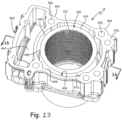
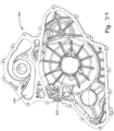
- block 12 is comprised of two halves, 12a and 12b.
- block portion 12a includes an inner wall at 72 defined by a perimeter wall at 74 defining an internal volume at 76.
- Internal wall 74 is machined to define a planar edge at 78 having a plurality of threaded apertures 80 defined within bosses 82.
- block portion 12b includes an inner wall 92 having a perimeter wall 94 defining an internal volume at 96.
- Wall 94 defines a planar edge at 98 having threaded apertures 100 defined within bosses 102.
- aperture 110 is defined by inner diameter 112 of boss 114 ( FIG. 5 ); and by diameter 116 defined by boss 118 ( FIG. 6 ).
- Aperture 110 is profiled for the mounting of a crank shaft as described herein.
- through aperture 120 is shown for a water pump drive shaft as described herein.
- Aperture 120 is defined by diameter 122 on block half 12a and diameter 124 on block half 12b, as shown in FIG. 7 .
- Aperture 130 is defined by a boss 132 and defines an internal diameter 134 ( FIG. 5 ). Aperture 130 communicates with opening 140 ( FIG. 6 ), which resides within housing 150, as further described herein.
- Block portion 12b further includes an aperture at 160 having a diameter at 162 for receiving an output shaft carrying drive sprocket 48.
- a water pump housing 170 is defined integral with block portion 12b.
- Water pump housing 170 includes multiple steps including 172, 174, 176, and 178, where step 178 defines the convolutes 180a, 180b ( FIG. 6 ) for the discharge water through housing 170.
- convolutes 180a, 180b are spiraled having a portion 182 intersecting with stepped portion 178, which spirals outwardly and together with portion 184 forms a water channel as a recess from planar surface 98.
- the convolutes 180a, 180b lead into openings 186, which move rearwardly as viewed in FIG. 6 to communicate with openings 188 as best viewed in FIG. 8 .
- Water openings 188 extend up to the upper planar surface 190 of the block 12, which surface is profiled to receive cylinder 14 as further described herein.
- passageways are defined between the convolutes 180a, 180b and upper faces 190a, 190b where portions 186a, 186b extend into the crankcase along an axis generally parallel with the rotational axis of the crankshaft; and portions 188a, 188b extend into the crankcase along an axis generally parallel with an axis of the cylinder bore.
- a single water pump housing 170 is integrally defined in the face 98 and defines two convolutes 180a and 180b where convolute 180a will feed cooling water to front cylinder assembly 8 and convolute 180b will feed water to rear cylinder assembly 10 as further described herein.
- centerlines 194a and 194b define an acute angle and also represent the centerline of the pistons within engine portion 4.
- centerline 194a intersects openings 186a, 188a while centerline 194b intersects opening 186b, 188b.
- centerline 194a generally bisects openings 186a, 188a while centerline 194b generally bisects opening 186b, 188b.
- upper planar surfaces 190a and 190b are defined by the two block halves 12a and 12b. Openings 200a and 200b are also provided defining a receiving area for cylinders 14, 24, respectively, as further described herein.
- block half 12a includes passageway 210a through surface 190a and passageway 210b extending through surface 190b, respectively. It should be appreciated that passageways 210a and 210b open into the open volume 76 ( FIG. 3 ), and provide access for cam chains as described herein.
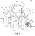
- Engine crank shaft 250 includes a shaft portion 252 extending from counterweight 254 and a shaft portion 256 extending from counterweight 258.
- Shaft portion 252 includes main journal 260, increased diameter portion 262 splined shaft portion 264 and post portion 266 having a threaded aperture at 268.
- Shaft portion 256 includes main journal 270, shaft portion 272, and tapered shaft portion 274.
- Crankshaft 250 further includes a crank pin journal 276 extending between counterweights 254, 258.
- a reduced mass portion 280 is provided as a hollowed out portion of counterweights 254 and 258 on an inside thereof defining an arcuate surface 282, a wall portion at 284, and a planar portion at 286.
- drive gear 300 is provided having internally splined coupling at 302, which corresponds with the splined exterior at 264 ( FIG. 9 ) of crank shaft 250.
- Drive gear 300 further includes exterior teeth at 304, wherein the rotation of crank shaft 250 causes a driving rotation of gear 300.
- Driven gear 310 is entrained with drive gear 200.
- Gears 312, 314 include gear teeth 316, 318, respectively, which correspond in pitch with teeth 304 of drive gear 300.
- Driven gear 310 is a backlash gear where gears 312, 314, are torsionally spring loaded relative to each other such that teeth 316, 318 are slightly rotationally spaced away from each other. This reduces the noise and vibration of the teeth engagement.
- Gear 310 is mounted to a shaft 320 having a shaft portion at 322, which terminates in a shoulder 324 ( FIG. 11A ) of shaft 320.
- Gear 310 is fixed relative to shaft portion 320 by way of a key and keyway as is known in the art.
- shaft 320 further includes a first gear 330 and a second gear at 332.
- gears 330 and 332 cooperate to drive cam chains as will be described in further detail herein.
- Shaft 320 further includes, at an opposite end, shoulder 336, diameter 338, and diameter 340.
- a gear 344 is positioned on outer diameter portion 338 and in abutment with shoulder 336.
- Gear 344 is also fixed relative to shaft 320 by way of a key and keyway as described above.
- Shaft 320 is rotatably held by two bearings, a ball bearing 372 positioned adjacent a first side (see FIG. 11A ) and a plain bearing (not shown) but positioned between surfaces 124, 340 in FIG. 11A ).
- Drive 350 includes a shaft 352 having a driven gear 354 on one end thereof entrained with drive gear 344.
- the pump impeller 356 is mounted to an opposite end of the shaft 352 and includes vanes 358.
- Impeller 356 includes an outer diameter portion 360.
- a seal 362 is provided having sealing ribs at 364.
- crankshaft 250 is shown coupled to drive gear 300, which is in turn drivingly coupled to gear 310.
- Gear 310 is coupled to shaft 320.
- Shaft 320 is shown with diameter portion 340 mounted in aperture 124 (see also FIG. 5 ) and with a bearing cap 370 coupling the opposite end 322 with a ball bearing 372, having balls 359.
- Bearing cap 370 is coupled directly to block 12.
- FIG. 11A also shows gears 344, 354 in meshing engagement and with gear 354 coupled to shaft 352 by way of fastener 380.
- Bearing 366 is positioned in aperture 120 and cooperates with shaft 352 for rotation of shaft 352. The direction of shaft rotation is shown by the arrow in FIG. 10 .
- FIG. 12 shows the linkage between crank shaft 250 and water pump impeller 356 and further shows a water pump cover 400 having a mating face at 402, which can mount flush with planar surface 98 ( FIG. 8 ).
- Water pump cover 400 may mount to water pump housing 170, for example, by way of fasteners through corresponding apertures 404a, 406a; 404b, 406b; and 404c, 406c.
- Housing 400 further includes an intake coupling at 410 to provide water into housing 170.
- Cover also includes an elongate portion 412a to enclose convolute 180a and elongate portion 412b to enclose convolute 180b.
- water pump 46 and, in particular, water pump impeller 356 is directly coupled to crank shaft 250, whereby rotation of crankshaft 250 causes movement of water through intake coupling 410 through water pump 46 delivering water at upper surfaces 198a, 190b ( FIG. 8 ) of engine block 12 through apertures 188a, 188b.
- FIGS. 13-16C cylinder 14 will be described in greater detail.
- cylinder 14 will be described in greater detail. It should also be noted that the description relates to cylinder 14, which is the cylinder for the front cylinder assembly 8, however, it should also be appreciated that cylinder 24 is substantially the same as that described with respect to cylinder 14; with the exception that cylinder 24 is in a mirror-image relationship.
- cylinder 14 includes a central cylinder portion 420 having an internal diameter portion at 422, which as should be appreciated receives a piston of the engine portion of the power train.
- Cylinder portion 422 includes an upper surface at 424, which is planar with the remaining upper surface portion 426 of cylinder 14.
- a lower planar surface 428 is defined in a parallel manner with upper planar surface 426.
- cylinder portion 420 has a lower portion 430 extending below lower planar surface 428.
- lower cylinder portion 430 extends below upper surface 190a ( FIG. 4 ) and into opening 200a ( FIG. 4 ) and into the crankcase of block 12.
- a wall portion 436 ( FIG. 13 ) encircles cylinder portion 420 and defines an internal circular surface at 438 spaced away from an internal surface 440 of cylindrical portion 420 defining a channel 442 therebetween.
- channel 442 is defined to receive cooling water such that cooling water circulates around cylinder portion 420 and cools cylinder portion 420 from heat caused by the combustion.
- a channel or opening 450 is defined between cylinder portion 420 and outer wall 436 as shown best in FIGS. 14 and 15 . It should be appreciated that opening 450 corresponds with passageway 188a ( FIG. 3 ) when cylinder 14 is positioned on surface 190a of block 12.
- Outer wall 436 further includes a plurality of bosses, such as 454 providing apertures at 456, which as should be appreciated, receives a stud placed in a top of block 12, as is known in the art.
- Cylinder 14 also includes an enclosed volume portion 460 providing an internal generally rectangular internal volume at 462, which corresponds with opening 210a ( FIG. 3 ) when cylinder 14 is positioned on block 12. Volume portion 462 allows the passage of cam chains upwardly to overhead cams as described herein.
- Cylinder 14 is designed to ensure adequate cooling around the cylinder.
- a slot 470 is provided on internal surface 438 adjacent to upper surface 426.
- an insert 480 is provided having a tapered body portion 482 having an internal arcuate surface at 484 having a tab portion at 486.
- Outer surface of insert 480 includes slot portions at 490 interrupting outer surface 492.
- insert 480 is shown inserted with tab 486 positioned in slot 470 and positioned over boss 454. As shown, insert 480 is positioned adjacent to water channel 450 and extends across internal water channel 442.
- Slots 490 allow some controlled passage of water through the insert, however, insert 480 creates a damming effect, causing water to circulate and fill the entire void or channel 442 to ensure proper cooling of the entire cylinder 420.
- insert 480 creates a damming effect, causing water to circulate and fill the entire void or channel 442 to ensure proper cooling of the entire cylinder 420.
- head 16 includes a lower planar surface 500 having a plurality of mounting apertures at 502, which correspond in location to apertures 456 ( FIG. 13 ) in order to position head in position relative to cylinder 14.
- Head 16 further includes a plurality of water receiving slots 504, which are positioned in a diametrical pattern, which matches the pattern of water channel 442 ( FIG. 13 ) on the upper side of cylinder 14.
- water flowing upward through cylinder 14, and through channel 442 flows into channels 504 to cool combustion chamber 510 of head 16.
- combustion chamber 510 includes two openings 512 for intake valves and two openings 514 for exhaust valves.
- Head 16 is a cast item including a plurality of internal chambers.
- an internal water chamber 520 is defined on an outside of combustion chamber 510 which communicates with water outlet 530 ( FIG. 17 ).
- water moving through cylinder 14 into head 16 travels through channels 504 into chamber 520 and exits at 530.
- water outlet 530 exits into the "V" of the engine and a corresponding opening on head 26 will also open into the "V" of the engine such that each of the outlets face the opposing cylinder assembly.
- an internal air chamber is defined, which communicates with intake ports, which in turn communicate with valve openings 512.
- Air intake port is shown at 544, which communicates with internal chamber 540 ( FIG. 19 ) and includes a flange 546 and mounting apertures at 548.
- exhaust valve openings 514 communicate with an internal exhaust chamber (not shown), which communicates with exhaust port 42 as shown in FIG. 18 .
- head 16 includes an upper planar surface at 550, and further defines cam receiving areas; area 552 for an exhaust cam and area 554 for an intake cam.
- head 16 includes transverse wall 560 having a semi-cylindrical receiving opening at 562 and transverse wall 564 having a semi-cylindrical opening at 566.
- transverse wall 560 further includes a semi-cylindrical opening at 572 and transverse wall 564 includes a semi-cylindrical opening at 574.
- cam shafts lie across the respective valve openings, 512, 514, and lay in their corresponding receiving areas 552, 554, as further described herein.
- head 16 also includes a central tubular portion 580, which may be cylindrical having an opening at 582, which may also be cylindrical. It should be appreciated that cylindrical opening 582 provides access to a spark plug receiving opening 586 ( FIG. 17 ), which in turn communicates with combustion chamber 510. Head 16 further includes passageway 590 for a cam chain, which passes through upper face 560 and lower face 500. It should be appreciated that passageway 590 corresponds with passageway 462 ( FIG. 13 ) and passageway 210a ( FIG. 4 ).
- FIGS. 20 and 21 the alignment of cylinder 14 and head 16 will be described.
- head 16 is shown positioned over cylinder 14, such that cam passageways 462 and 590 align providing a consistent vertical passageway; furthermore, water channel 442 in the top of cylinder 14 is shown aligned with water chamber 520 and with receiving openings 504.
- coolant water travels upwardly through the block 12 through passageway 442 of cylinder 14 upwardly through openings 504 into chamber 520 to cool both the cylinder and combustion chamber 510 and exit through port 530 ( FIG. 20 ).
- FIG. 22 the intersection of convolute 180a and upper passageway 188a of block 12 is shown in combination with the communication of passageways 450, 504, and chamber 520.
- thermostat 40 sits in the "V" of the engine portion 4 intermediate the front cylinder assembly 8 and the rear cylinder assembly 10.
- Thermostat assembly 40 includes a thermostat 600 having a first input at 602 and a second input at 604.
- Thermostat 600 includes two outlets; one at 606 and a second at 608.
- Inlet 602 communicates with water outlet port 530 (see also FIG. 17 ) by way of a hose 610.
- hose 610 is fixed in place by way of clamps such as 612, 614.
- a second hose 620 is provided with a first end coupled to inlet 604 and a second end coupled to a corresponding water outlet port 530 of cylinder assembly 10.
- coolant water traveling up through cylinder assemblies 8 and 10 as described above in relation to FIG. 22 exits through corresponding water ports 530 in head 16 and into hoses 610, 620, and flows into thermostat 600 through ports 602, 604.
- Hose 630 has a first end 632 coupled to port 608 by way of clamp 634, and a second end 636 coupled to a return port ( FIG. 2 ) by way of a coupling (not shown).
- Coupling 644 returns the coolant water directly to water pump 46 to recirculate the water through the convolutes and back through the front and rear cylinder assemblies 8, 10, as previously described.
- the radiator will have an inlet port coupled to port 606 and an outlet port coupled to port 410 ( FIG. 2 ) to provide a closed system for the coolant water.
- An exemplary motorcycle for use with power train 2 is described more fully in our co-pending patent application serial no. 61/799,880 filed March 15, 2013 , (Attorney Docket No. PLR-05-25858.01P-US-e).
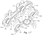
- cam carrier 650 having a body portion 652 for overlying cam receiving area 552 and a body portion 654 for overlying cam receiving area 554.
- Body portion 652 includes apertures 704a for alignment with apertures 594a; apertures 704b for alignment with apertures 594b; apertures 706a for alignment with apertures 596a; and apertures 706b for alignment with apertures 596b.
- cam carrier 650 also includes semi-cylindrical recess 712, which corresponds with semi-cylindrical recess 562; and a semi-cylindrical recess 716, which corresponds to recess 566 ( FIG.
- Body portion 654 includes a semi-cylindrical recess 718 corresponding to recess 572 and recess 720 corresponding to recess 574 ( FIG. 20 ).
- a lower surface of cam carrier 650 also includes a planar surface 732, which can fit flushly with top surface 550 ( FIG. 19 ) of head 16.
- cam carrier 650 further includes a central tubular portion 740 which may be cylindrical, having an upper surface at 742 and a lower surface at 744. As shown in FIG. 25 , lower surface 744 includes an undercut portion 746, defining an annular recess, for recessing a seal (not shown). Lower surface 744 is profiled to cooperate with cylindrical portion 580 ( FIG. 19 ) and cylindrical portion 740 further includes an inner diameter at 750, which is substantially the same as inner diameter 582 ( FIG. 19 ) of cylindrical portion 580.
- cams may be positioned in the receiving areas 552 and 554 with the cam gear positioned in area 590 ( FIG. 19 ). Cam carrier 650 may then be received over the cams and coupled to the head to retain the cams in position in their respective areas 552, 554 and above intake and exhaust valves.
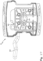
- valve cover 18 is shown having a body portion 780 having a central area 782 having an opening at 784 defined by a cylindrical member 786.
- cylindrical member 786 has a seal 788 having an inner channel 790.
- Seal 788 could be a discreet seal or could be integrally molded with cylindrical portion 786. It should be appreciated that seal 786, and more particularly channel 790, is received over upper end 742 ( FIG. 25 ) of cylindrical portion 740 of cam carrier 650.
- body portion 780 is generally curved along its top side having end walls 796 and 798.
- An exit port is positioned at 800 coupled to a breather tube 802 as will be described herein.
- valve cover 18 An underside of valve cover 18 includes a baffle plate 810 defined by a plate portion 812.
- Plate portion 812 includes a circular opening 814 receivable over tubular portion 786.
- Baffle plate 812 further includes upright baffles 816 and fasteners 818 couple baffles plate 810 within valve cover 18.
- Hose 802 is then connected to an air box of a motorcycle to recycle unspent gases that leak through the combustion chamber, back to the air box and air cleaner for recycling of the unspent gasses.
- cam retainer 650 sits above head 16 and is positioned over the cams to retain the cams in the head.
- the cam carrier comprises an upstanding tubular wall 740 which defines the aperture 750.
- the upstanding tubular wall 740 defines the lower planar surface 744 (see FIG. 25 ) profiled to interface with an upper planar surface 550 of the head.
- a seal (see FIG. 30 ) is at the interface of the lower planar surface 744 of the upstanding tubular wall and the upper planar surface 550 of the head.
- Central cylindrical portion 740 is positioned over head 16 and in alignment with opening 582 (see FIG. 22 ).
- Valve cover 18 is shown positioned over cam carrier 650 such that aperture 784 (see FIG. 26 ) overlies the aperture 750. Seal 788 is in position over cylindrical portion 740 thereby sealing valve cover 18 to head 16, through the cam carrier 650.
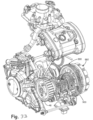
- drive gear 300 which is coupled directly to crank shaft 250 drives gear 310.
- gear 310 drives gears 330 and gear 332, which ultimately drive cam chains.
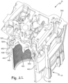
- Cam chains 850a and 850b are shown in FIG. 29 , which would be entrained to gears 330, 332, respectively.
- Power train 2 further includes an exhaust timing gear 852a and an intake timing gear 854a and exhaust timing gear 852b and intake timing gear 854b.
- timing chains extend through the passageways defined by individual passageway 210a ( FIG. 3 ), passageways 462 ( FIG. 13 ), and passageway 590 ( FIG. 18 ).
- FIG. 29 also shows timing chain tensioners 860a, 860b, and 862b.
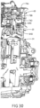
- a front driven gear 870 which drives an oil pump 872 ( FIG. 32 ), which is positioned generally and directly behind driven gear 870.
- Oil pump 872 has an oil pick up line 874 having a snorkel at 876 (see FIG. 31 ).
- drive gear 300 also drives 880 (see FIG. 33 ), which drives clutch 882.
- Clutch 882 drives a shaft 884 (see FIG. 31 ) having a plurality of gears 890 in meshing engagement with a plurality of gears 900 ( FIG. 32 ).
- Gears 900 are ultimately coupled to output sprocket 48 (see FIG. 32 ), which will be coupled to motorcycle rear wheel by way of a belt (not shown).
- driven gear 300 drives multiple aspects of the power train from a single gear directly driven off of the crank shaft.
- driven gear 300 drives gear 310, which in turn drives both cam chains 850a and 850b, which in turn drives the overhead cams.
- drive gear 300 drives the water pump through the coupling engagement of the water pump drive shaft 350 to driven gear 310.
- Drive gear 300 further drives driven gear 870, which in turn drives oil pump 872.
- drive gear 300 drives gear 880 driving clutch 882.
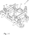
- the sealing between most interfacial components includes a press in place square bead seal, such as seal 910, which provides a robust seal eliminating leaks.
- a speed sensor 920 is provided, which moves laterally with the laterally movable gears.
- the water pump cover 400 is shown which includes a portion 930 to cover the water pump housing 170, and a portion 932 to cover the generator; the common cover makes the parts seem seamless.
- the small cover or badge 940 is removable for testing purposes.
- the heads 16 could be of various sizes to accommodate different displacements. It is also possible to provide different aesthetic looking families, due to modularity of the components. For example, different cylinders, heads, valve covers, and other covers could be provided with different aesthetic looks, yet with similar coupling to the block 12.
Landscapes
- Engineering & Computer Science (AREA)
- Mechanical Engineering (AREA)
- General Engineering & Computer Science (AREA)
- Chemical & Material Sciences (AREA)
- Combustion & Propulsion (AREA)
- Cylinder Crankcases Of Internal Combustion Engines (AREA)
- Lubrication Of Internal Combustion Engines (AREA)
Priority Applications (1)
| Application Number | Priority Date | Filing Date | Title |
|---|---|---|---|
| EP25168105.2A EP4556695A3 (en) | 2013-03-15 | 2014-03-14 | Engine |
Applications Claiming Priority (3)
| Application Number | Priority Date | Filing Date | Title |
|---|---|---|---|
| US201361801033P | 2013-03-15 | 2013-03-15 | |
| PCT/US2014/028857 WO2014144444A2 (en) | 2013-03-15 | 2014-03-14 | Engine |
| EP14719169.6A EP2971623B1 (en) | 2013-03-15 | 2014-03-14 | Engine |
Related Parent Applications (1)
| Application Number | Title | Priority Date | Filing Date |
|---|---|---|---|
| EP14719169.6A Division EP2971623B1 (en) | 2013-03-15 | 2014-03-14 | Engine |
Related Child Applications (1)
| Application Number | Title | Priority Date | Filing Date |
|---|---|---|---|
| EP25168105.2A Division EP4556695A3 (en) | 2013-03-15 | 2014-03-14 | Engine |
Publications (2)
| Publication Number | Publication Date |
|---|---|
| EP3705691A1 EP3705691A1 (en) | 2020-09-09 |
| EP3705691B1 true EP3705691B1 (en) | 2025-04-23 |
Family
ID=50543693
Family Applications (3)
| Application Number | Title | Priority Date | Filing Date |
|---|---|---|---|
| EP20172553.8A Active EP3705691B1 (en) | 2013-03-15 | 2014-03-14 | Engine |
| EP25168105.2A Pending EP4556695A3 (en) | 2013-03-15 | 2014-03-14 | Engine |
| EP14719169.6A Active EP2971623B1 (en) | 2013-03-15 | 2014-03-14 | Engine |
Family Applications After (2)
| Application Number | Title | Priority Date | Filing Date |
|---|---|---|---|
| EP25168105.2A Pending EP4556695A3 (en) | 2013-03-15 | 2014-03-14 | Engine |
| EP14719169.6A Active EP2971623B1 (en) | 2013-03-15 | 2014-03-14 | Engine |
Country Status (8)
| Country | Link |
|---|---|
| US (4) | US9194278B2 (https=) |
| EP (3) | EP3705691B1 (https=) |
| JP (2) | JP2016515671A (https=) |
| CN (1) | CN105378235A (https=) |
| AU (3) | AU2014229101B2 (https=) |
| BR (1) | BR112015021233A2 (https=) |
| CA (1) | CA2902341A1 (https=) |
| WO (1) | WO2014144444A2 (https=) |
Families Citing this family (19)
| Publication number | Priority date | Publication date | Assignee | Title |
|---|---|---|---|---|
| JP6347150B2 (ja) * | 2014-05-14 | 2018-06-27 | スズキ株式会社 | 自動二輪車のエンジン冷却装置 |
| AT517965B1 (de) * | 2016-03-22 | 2017-06-15 | MAN Truck & Bus Österreich AG | Anordnung von Nebenaggregaten bei einer Brennkraftmaschine |
| DE102017003390A1 (de) * | 2016-04-26 | 2017-10-26 | Ford Global Technologies, Llc | Per Zahnrad angetriebene Dieselkraftstoff-Einspritzpumpe eines Motors |
| US10422253B2 (en) | 2016-04-26 | 2019-09-24 | Ford Global Technologies, Llc | Cam drive system for an engine |
| CA3055952A1 (en) | 2017-03-10 | 2018-09-13 | Indian Motorcycle International, LLC | Two-wheeled vehicle |
| US10550754B2 (en) * | 2017-05-15 | 2020-02-04 | Polaris Industries Inc. | Engine |
| US10655536B1 (en) | 2017-05-24 | 2020-05-19 | Indian Motorcycle International, LLC | Engine |
| US10589621B1 (en) | 2017-05-24 | 2020-03-17 | Indian Motorcycle International, LLC | Two-wheeled vehicle |
| US10371249B1 (en) | 2017-05-24 | 2019-08-06 | Indian Motorcycle International, LLC | Engine |
| US10221727B1 (en) | 2017-05-24 | 2019-03-05 | Indian Motorcycle International, LLC | Engine |
| JP6369614B1 (ja) * | 2017-09-29 | 2018-08-08 | トヨタ自動車株式会社 | 車両用ケーシング |
| USD911879S1 (en) | 2018-09-10 | 2021-03-02 | Indian Motorcycle International, LLC | Motorcycle |
| US11077910B2 (en) | 2018-09-28 | 2021-08-03 | Indian Motorcycle International, LLC | Two-wheeled vehicle |
| CN109882279B (zh) * | 2019-02-15 | 2020-09-08 | 宁波吉利罗佑发动机零部件有限公司 | 链条冷却结构及具有其的发动机 |
| US11060441B2 (en) * | 2019-04-05 | 2021-07-13 | Perkins Engines Company Limited | Water pump with twin return ports |
| US11578647B2 (en) | 2020-03-11 | 2023-02-14 | Arctic Cat Inc. | Engine |
| US12187127B2 (en) | 2020-05-15 | 2025-01-07 | Polaris Industries Inc. | Off-road vehicle |
| US11691674B2 (en) | 2020-05-15 | 2023-07-04 | Polaris Industries Inc. | Off-road vehicle |
| MX2023006716A (es) | 2022-06-13 | 2023-12-14 | Polaris Inc | Tren de potencia para vehiculo utilitario. |
Citations (4)
| Publication number | Priority date | Publication date | Assignee | Title |
|---|---|---|---|---|
| JPH01277611A (ja) * | 1988-04-30 | 1989-11-08 | Mazda Motor Corp | V型エンジンの潤滑装置 |
| JPH0586858A (ja) * | 1991-09-26 | 1993-04-06 | Toyota Motor Corp | V型エンジンのシリンダブロツク構造 |
| DE19641052A1 (de) * | 1995-10-06 | 1997-04-10 | Toyota Motor Co Ltd | Zylinderblockaufbau für einen V-Motor |
| JP2002168146A (ja) * | 2000-12-04 | 2002-06-14 | Honda Motor Co Ltd | V型多気筒エンジン |
Family Cites Families (61)
| Publication number | Priority date | Publication date | Assignee | Title |
|---|---|---|---|---|
| US1461711A (en) * | 1920-02-09 | 1923-07-10 | Gen Motors Corp | Cooling-liquid-pump mounting for internal-combustion engines |
| US3452610A (en) * | 1968-01-17 | 1969-07-01 | Us Army | Interchangeable dual gear train assemblies |
| US4155333A (en) * | 1977-04-07 | 1979-05-22 | Brunswick Corporation | Centrifugal water pump for internal combustion engines |
| US4321896A (en) * | 1979-12-18 | 1982-03-30 | Cummins Engine Company | Gear plate assembly for mounting and positioning an accessory drive train |
| DE3140195C2 (de) * | 1981-10-09 | 1984-12-20 | Daimler-Benz Ag, 7000 Stuttgart | Flüssigkeits-Reibungskupplung für das Kühlgebläse einer Brennkraftmaschine |
| JPS5935637U (ja) * | 1982-08-31 | 1984-03-06 | スズキ株式会社 | オ−バヘツドカム駆動用中間軸の取付構造 |
| JPS59109019U (ja) | 1983-01-12 | 1984-07-23 | 日立電線株式会社 | シ−ルド付絶縁電線 |
| DE3326318A1 (de) * | 1983-07-21 | 1985-01-31 | Dr.Ing.H.C. F. Porsche Ag, 7000 Stuttgart | Wasserpumpe einer hubkolben-brennkraftmaschine |
| JPS6119612A (ja) | 1984-07-06 | 1986-01-28 | Mitsui Petrochem Ind Ltd | ポリアセチレンを含む振動体材料とその製造法 |
| JPS6119612U (ja) * | 1984-07-10 | 1986-02-04 | トヨタ自動車株式会社 | シリンダヘツドカバ− |
| US4756280A (en) * | 1984-12-21 | 1988-07-12 | Kawasaki Jukogyo Kabushiki Kaisha | Cooling system for vertical shaft V-type engine |
| JP2537205B2 (ja) * | 1986-07-09 | 1996-09-25 | 本田技研工業株式会社 | 内燃機関の動弁装置 |
| JPS6318109A (ja) * | 1986-07-09 | 1988-01-26 | Honda Motor Co Ltd | 内燃機関の動弁機構 |
| JPS63186906A (ja) * | 1987-01-28 | 1988-08-02 | Honda Motor Co Ltd | 内燃機関 |
| JPS643706A (en) | 1987-06-26 | 1989-01-09 | Mitsubishi Electric Corp | Controller |
| JPH0621451B2 (ja) | 1987-07-01 | 1994-03-23 | 強化土エンジニヤリング株式会社 | 地盤注入工法 |
| JPH01110815A (ja) * | 1987-10-21 | 1989-04-27 | Mazda Motor Corp | エンジンのカムキャップ構造 |
| JPH01103706U (https=) * | 1987-12-28 | 1989-07-13 | ||
| DE3914124A1 (de) * | 1988-04-30 | 1989-11-09 | Mazda Motor | V-motor |
| JP2525239Y2 (ja) * | 1990-06-08 | 1997-02-05 | マツダ株式会社 | V型エンジンの冷却水通路構造 |
| JPH04269324A (ja) * | 1991-02-22 | 1992-09-25 | Suzuki Motor Corp | 内燃機関のウォータポンプ装置 |
| US5279265A (en) * | 1991-07-26 | 1994-01-18 | Nissan Motor Co., Ltd. | V-type internal combustion engine with improved water pump arrangement |
| US5228420A (en) * | 1992-09-25 | 1993-07-20 | Tsuchiya Mfg. Co., Ltd. | Valve rocker cover |
| JP3137514B2 (ja) * | 1993-09-25 | 2001-02-26 | マツダ株式会社 | 多気筒エンジンの補機駆動装置 |
| JP2584600B2 (ja) * | 1994-12-05 | 1997-02-26 | 本田技研工業株式会社 | 内燃機関の動弁装置 |
| JP3591115B2 (ja) * | 1996-03-11 | 2004-11-17 | スズキ株式会社 | V型4サイクルエンジン |
| DE19633485B4 (de) * | 1996-08-20 | 2004-11-18 | Dr.Ing.H.C. F. Porsche Ag | Flüssigkeitsgekühlte Brennkraftmaschine |
| JP3714437B2 (ja) * | 1996-12-17 | 2005-11-09 | 本田技研工業株式会社 | 内燃機関のクランクケース締付構造 |
| DE19840659A1 (de) * | 1998-09-05 | 2000-03-09 | Volkswagen Ag | Steuertrieb für Nockenwellenanordnungen |
| JP2000161138A (ja) * | 1998-12-01 | 2000-06-13 | Harness Syst Tech Res Ltd | シリンダヘッドカバー装置 |
| US6109221A (en) * | 1999-02-17 | 2000-08-29 | Kohler Co. | Engine with integral coolant pump |
| US6354249B1 (en) * | 2000-06-13 | 2002-03-12 | Kohler Co. | Engine with coolant pump |
| US6581550B2 (en) * | 2000-06-30 | 2003-06-24 | Toyota Jidosha Kabushiki Kaisha | Cooling structure of cylinder block |
| EP1191203A3 (en) * | 2000-09-26 | 2003-04-02 | Bombardier-Rotax GmbH | Arrangement for mass balancing a v-type internal combustion engine |
| JP2002168416A (ja) | 2000-12-04 | 2002-06-14 | O Saamu:Kk | 愛玩動物用火葬車 |
| US6453868B1 (en) * | 2000-12-15 | 2002-09-24 | Deere & Company | Engine timing gear cover with integral coolant flow passages |
| DE10100373B4 (de) * | 2001-01-05 | 2004-03-25 | Dr.Ing.H.C. F. Porsche Ag | Wasserpumpe zur Kühlmittelförderung in einer Brennkraftmaschine |
| JP2002276596A (ja) * | 2001-03-14 | 2002-09-25 | Yamaha Motor Co Ltd | 渦巻ポンプ |
| DE10306392A1 (de) * | 2003-02-15 | 2004-08-26 | Volkswagen Ag | Stirnrad-Nockenwellenantrieb für eine Brennkraftmaschine |
| JP4051019B2 (ja) | 2003-10-17 | 2008-02-20 | トヨタ自動車株式会社 | シリンダブロックの冷却構造 |
| JP2006348837A (ja) * | 2005-06-15 | 2006-12-28 | Honda Motor Co Ltd | シリンダヘッドカバーの支持構造 |
| JP4781760B2 (ja) * | 2005-09-14 | 2011-09-28 | 川崎重工業株式会社 | エンジン |
| JP4553824B2 (ja) * | 2005-11-02 | 2010-09-29 | 本田技研工業株式会社 | 水冷式内燃機関 |
| CN2881116Y (zh) * | 2006-01-24 | 2007-03-21 | 沈阳华晨金杯汽车有限公司 | 新型涡轮增压发动机 |
| CN200940501Y (zh) * | 2006-07-11 | 2007-08-29 | 光阳工业股份有限公司 | 引擎的吹漏气装置 |
| WO2008073292A2 (en) * | 2006-12-08 | 2008-06-19 | Caritas St. Elizabeth's Medical Center Of Boston, Inc. | Method for protecting renal tubular epithelial cells from radiocontrast nephro parhy (rcn) |
| JP4727600B2 (ja) * | 2007-01-31 | 2011-07-20 | 本田技研工業株式会社 | 頭上弁式内燃機関 |
| JP2008223594A (ja) | 2007-03-13 | 2008-09-25 | Yamaha Motor Co Ltd | 内燃機関およびそれを備えた車両 |
| US20100031902A1 (en) * | 2007-10-10 | 2010-02-11 | Brunswick Corporation | Outboard motor cooling system with inserts to affect operating temperatures |
| JP5119029B2 (ja) * | 2008-04-10 | 2013-01-16 | 川崎重工業株式会社 | エンジン |
| CN201250716Y (zh) * | 2008-06-13 | 2009-06-03 | 奇瑞汽车股份有限公司 | 一种发动机气门室罩盖 |
| US8011342B2 (en) | 2008-07-16 | 2011-09-06 | Polaris Industries Inc. | Wet oil sump for four cycle engine |
| JP5078805B2 (ja) * | 2008-08-26 | 2012-11-21 | 川崎重工業株式会社 | エンジンの潤滑構造 |
| JP5078806B2 (ja) * | 2008-08-26 | 2012-11-21 | 川崎重工業株式会社 | エンジンの潤滑構造 |
| JP5297155B2 (ja) * | 2008-11-07 | 2013-09-25 | 株式会社マーレ フィルターシステムズ | シリンダヘッドカバーのガスケット取付構造 |
| EP2308708B1 (de) | 2009-09-16 | 2016-08-17 | swissauto powersport llc | Elektrofahrzeug mit Reichweitenverlängerung |
| JP5415363B2 (ja) * | 2010-06-11 | 2014-02-12 | 本田技研工業株式会社 | 内燃機関のシリンダヘッド構造 |
| CA2811026C (en) | 2010-09-23 | 2019-02-12 | Polaris Industries Inc. | Engine |
| CN102953858B (zh) * | 2011-08-17 | 2014-09-17 | 比亚迪股份有限公司 | 一种发动机冷却水套及发动机 |
| CN202702621U (zh) * | 2012-07-27 | 2013-01-30 | 哈尔滨哈轻塑胶有限公司 | 汽车气门室罩壳振动摩擦焊接结构 |
| WO2014075091A2 (en) | 2012-11-12 | 2014-05-15 | Indian Motorcycle International, LLC | Two-wheeled vehicle |
-
2014
- 2014-03-14 WO PCT/US2014/028857 patent/WO2014144444A2/en not_active Ceased
- 2014-03-14 AU AU2014229101A patent/AU2014229101B2/en not_active Ceased
- 2014-03-14 EP EP20172553.8A patent/EP3705691B1/en active Active
- 2014-03-14 EP EP25168105.2A patent/EP4556695A3/en active Pending
- 2014-03-14 JP JP2016502927A patent/JP2016515671A/ja active Pending
- 2014-03-14 CA CA2902341A patent/CA2902341A1/en not_active Abandoned
- 2014-03-14 US US14/214,033 patent/US9194278B2/en active Active
- 2014-03-14 BR BR112015021233A patent/BR112015021233A2/pt not_active IP Right Cessation
- 2014-03-14 CN CN201480011350.6A patent/CN105378235A/zh active Pending
- 2014-03-14 EP EP14719169.6A patent/EP2971623B1/en active Active
-
2015
- 2015-10-20 US US14/887,823 patent/US9638070B2/en active Active
-
2016
- 2016-07-08 AU AU2016204751A patent/AU2016204751B2/en not_active Ceased
-
2017
- 2017-03-21 US US15/465,543 patent/US10036311B2/en active Active
-
2018
- 2018-07-25 US US16/044,660 patent/US10323568B2/en active Active
- 2018-08-09 AU AU2018214090A patent/AU2018214090B2/en not_active Ceased
-
2019
- 2019-08-19 JP JP2019149774A patent/JP7382172B2/ja active Active
Patent Citations (4)
| Publication number | Priority date | Publication date | Assignee | Title |
|---|---|---|---|---|
| JPH01277611A (ja) * | 1988-04-30 | 1989-11-08 | Mazda Motor Corp | V型エンジンの潤滑装置 |
| JPH0586858A (ja) * | 1991-09-26 | 1993-04-06 | Toyota Motor Corp | V型エンジンのシリンダブロツク構造 |
| DE19641052A1 (de) * | 1995-10-06 | 1997-04-10 | Toyota Motor Co Ltd | Zylinderblockaufbau für einen V-Motor |
| JP2002168146A (ja) * | 2000-12-04 | 2002-06-14 | Honda Motor Co Ltd | V型多気筒エンジン |
Also Published As
| Publication number | Publication date |
|---|---|
| US10323568B2 (en) | 2019-06-18 |
| EP2971623A2 (en) | 2016-01-20 |
| EP3705691A1 (en) | 2020-09-09 |
| US20140261258A1 (en) | 2014-09-18 |
| US9638070B2 (en) | 2017-05-02 |
| AU2014229101B2 (en) | 2016-06-02 |
| US20160040561A1 (en) | 2016-02-11 |
| EP4556695A2 (en) | 2025-05-21 |
| US10036311B2 (en) | 2018-07-31 |
| JP2016515671A (ja) | 2016-05-30 |
| CA2902341A1 (en) | 2014-09-18 |
| US20170191408A1 (en) | 2017-07-06 |
| JP7382172B2 (ja) | 2023-11-16 |
| CN105378235A (zh) | 2016-03-02 |
| WO2014144444A2 (en) | 2014-09-18 |
| EP4556695A3 (en) | 2025-08-20 |
| JP2019215006A (ja) | 2019-12-19 |
| AU2014229101A1 (en) | 2015-10-22 |
| WO2014144444A3 (en) | 2016-03-10 |
| AU2016204751A1 (en) | 2016-07-28 |
| AU2016204751B2 (en) | 2018-05-10 |
| US9194278B2 (en) | 2015-11-24 |
| EP2971623B1 (en) | 2020-05-13 |
| BR112015021233A2 (pt) | 2017-07-18 |
| US20180328272A1 (en) | 2018-11-15 |
| AU2018214090A1 (en) | 2018-08-30 |
| AU2018214090B2 (en) | 2019-04-04 |
Similar Documents
| Publication | Publication Date | Title |
|---|---|---|
| EP3705691B1 (en) | Engine | |
| US7637236B2 (en) | Cylinder head for an overhead-cam internal combustion engine, engine incorporating same, and vehicle incorporating the engine | |
| US6598595B2 (en) | Breather device for motorcycle | |
| US10294889B2 (en) | Engine | |
| US20020134603A1 (en) | Snowmobile | |
| JP5077686B2 (ja) | 内燃機関の冷却装置 | |
| JP3435143B2 (ja) | オーバヘッドカム型v型エンジン | |
| WO2018213216A1 (en) | Engine | |
| JP4947436B2 (ja) | 内燃機関の冷却構造 | |
| US7156060B2 (en) | Cam drive gear and valve operating system drive gear for engine | |
| US7201119B2 (en) | Vehicular power unit | |
| US8528515B2 (en) | Crankcase of internal combustion engine | |
| JP2013170548A (ja) | 内燃機関のオイル噴射装置 | |
| JP2009236051A (ja) | 内燃機関の冷却装置 |
Legal Events
| Date | Code | Title | Description |
|---|---|---|---|
| PUAI | Public reference made under article 153(3) epc to a published international application that has entered the european phase |
Free format text: ORIGINAL CODE: 0009012 |
|
| STAA | Information on the status of an ep patent application or granted ep patent |
Free format text: STATUS: THE APPLICATION HAS BEEN PUBLISHED |
|
| AC | Divisional application: reference to earlier application |
Ref document number: 2971623 Country of ref document: EP Kind code of ref document: P |
|
| AK | Designated contracting states |
Kind code of ref document: A1 Designated state(s): AL AT BE BG CH CY CZ DE DK EE ES FI FR GB GR HR HU IE IS IT LI LT LU LV MC MK MT NL NO PL PT RO RS SE SI SK SM TR |
|
| STAA | Information on the status of an ep patent application or granted ep patent |
Free format text: STATUS: REQUEST FOR EXAMINATION WAS MADE |
|
| 17P | Request for examination filed |
Effective date: 20210308 |
|
| RBV | Designated contracting states (corrected) |
Designated state(s): AL AT BE BG CH CY CZ DE DK EE ES FI FR GB GR HR HU IE IS IT LI LT LU LV MC MK MT NL NO PL PT RO RS SE SI SK SM TR |
|
| STAA | Information on the status of an ep patent application or granted ep patent |
Free format text: STATUS: EXAMINATION IS IN PROGRESS |
|
| 17Q | First examination report despatched |
Effective date: 20230405 |
|
| P01 | Opt-out of the competence of the unified patent court (upc) registered |
Effective date: 20230514 |
|
| GRAP | Despatch of communication of intention to grant a patent |
Free format text: ORIGINAL CODE: EPIDOSNIGR1 |
|
| STAA | Information on the status of an ep patent application or granted ep patent |
Free format text: STATUS: GRANT OF PATENT IS INTENDED |
|
| INTG | Intention to grant announced |
Effective date: 20241114 |
|
| GRAS | Grant fee paid |
Free format text: ORIGINAL CODE: EPIDOSNIGR3 |
|
| GRAA | (expected) grant |
Free format text: ORIGINAL CODE: 0009210 |
|
| STAA | Information on the status of an ep patent application or granted ep patent |
Free format text: STATUS: THE PATENT HAS BEEN GRANTED |
|
| AC | Divisional application: reference to earlier application |
Ref document number: 2971623 Country of ref document: EP Kind code of ref document: P |
|
| AK | Designated contracting states |
Kind code of ref document: B1 Designated state(s): AL AT BE BG CH CY CZ DE DK EE ES FI FR GB GR HR HU IE IS IT LI LT LU LV MC MK MT NL NO PL PT RO RS SE SI SK SM TR |
|
| REG | Reference to a national code |
Ref country code: GB Ref legal event code: FG4D |
|
| REG | Reference to a national code |
Ref country code: CH Ref legal event code: EP |
|
| REG | Reference to a national code |
Ref country code: DE Ref legal event code: R096 Ref document number: 602014091847 Country of ref document: DE |
|
| REG | Reference to a national code |
Ref country code: IE Ref legal event code: FG4D |
|
| REG | Reference to a national code |
Ref country code: NL Ref legal event code: MP Effective date: 20250423 |
|
| PG25 | Lapsed in a contracting state [announced via postgrant information from national office to epo] |
Ref country code: NL Free format text: LAPSE BECAUSE OF FAILURE TO SUBMIT A TRANSLATION OF THE DESCRIPTION OR TO PAY THE FEE WITHIN THE PRESCRIBED TIME-LIMIT Effective date: 20250423 |
|
| REG | Reference to a national code |
Ref country code: AT Ref legal event code: MK05 Ref document number: 1787939 Country of ref document: AT Kind code of ref document: T Effective date: 20250423 |
|
| PG25 | Lapsed in a contracting state [announced via postgrant information from national office to epo] |
Ref country code: FI Free format text: LAPSE BECAUSE OF FAILURE TO SUBMIT A TRANSLATION OF THE DESCRIPTION OR TO PAY THE FEE WITHIN THE PRESCRIBED TIME-LIMIT Effective date: 20250423 Ref country code: ES Free format text: LAPSE BECAUSE OF FAILURE TO SUBMIT A TRANSLATION OF THE DESCRIPTION OR TO PAY THE FEE WITHIN THE PRESCRIBED TIME-LIMIT Effective date: 20250423 Ref country code: PT Free format text: LAPSE BECAUSE OF FAILURE TO SUBMIT A TRANSLATION OF THE DESCRIPTION OR TO PAY THE FEE WITHIN THE PRESCRIBED TIME-LIMIT Effective date: 20250825 |
|
| REG | Reference to a national code |
Ref country code: LT Ref legal event code: MG9D |
|
| PG25 | Lapsed in a contracting state [announced via postgrant information from national office to epo] |
Ref country code: GR Free format text: LAPSE BECAUSE OF FAILURE TO SUBMIT A TRANSLATION OF THE DESCRIPTION OR TO PAY THE FEE WITHIN THE PRESCRIBED TIME-LIMIT Effective date: 20250724 Ref country code: NO Free format text: LAPSE BECAUSE OF FAILURE TO SUBMIT A TRANSLATION OF THE DESCRIPTION OR TO PAY THE FEE WITHIN THE PRESCRIBED TIME-LIMIT Effective date: 20250723 |
|
| PG25 | Lapsed in a contracting state [announced via postgrant information from national office to epo] |
Ref country code: PL Free format text: LAPSE BECAUSE OF FAILURE TO SUBMIT A TRANSLATION OF THE DESCRIPTION OR TO PAY THE FEE WITHIN THE PRESCRIBED TIME-LIMIT Effective date: 20250423 |
|
| PG25 | Lapsed in a contracting state [announced via postgrant information from national office to epo] |
Ref country code: BG Free format text: LAPSE BECAUSE OF FAILURE TO SUBMIT A TRANSLATION OF THE DESCRIPTION OR TO PAY THE FEE WITHIN THE PRESCRIBED TIME-LIMIT Effective date: 20250423 |
|
| PG25 | Lapsed in a contracting state [announced via postgrant information from national office to epo] |
Ref country code: HR Free format text: LAPSE BECAUSE OF FAILURE TO SUBMIT A TRANSLATION OF THE DESCRIPTION OR TO PAY THE FEE WITHIN THE PRESCRIBED TIME-LIMIT Effective date: 20250423 |
|
| PG25 | Lapsed in a contracting state [announced via postgrant information from national office to epo] |
Ref country code: AT Free format text: LAPSE BECAUSE OF FAILURE TO SUBMIT A TRANSLATION OF THE DESCRIPTION OR TO PAY THE FEE WITHIN THE PRESCRIBED TIME-LIMIT Effective date: 20250423 |
|
| PG25 | Lapsed in a contracting state [announced via postgrant information from national office to epo] |
Ref country code: RS Free format text: LAPSE BECAUSE OF FAILURE TO SUBMIT A TRANSLATION OF THE DESCRIPTION OR TO PAY THE FEE WITHIN THE PRESCRIBED TIME-LIMIT Effective date: 20250723 |
|
| PG25 | Lapsed in a contracting state [announced via postgrant information from national office to epo] |
Ref country code: IS Free format text: LAPSE BECAUSE OF FAILURE TO SUBMIT A TRANSLATION OF THE DESCRIPTION OR TO PAY THE FEE WITHIN THE PRESCRIBED TIME-LIMIT Effective date: 20250823 |
|
| PG25 | Lapsed in a contracting state [announced via postgrant information from national office to epo] |
Ref country code: LV Free format text: LAPSE BECAUSE OF FAILURE TO SUBMIT A TRANSLATION OF THE DESCRIPTION OR TO PAY THE FEE WITHIN THE PRESCRIBED TIME-LIMIT Effective date: 20250423 |
|
| PG25 | Lapsed in a contracting state [announced via postgrant information from national office to epo] |
Ref country code: DK Free format text: LAPSE BECAUSE OF FAILURE TO SUBMIT A TRANSLATION OF THE DESCRIPTION OR TO PAY THE FEE WITHIN THE PRESCRIBED TIME-LIMIT Effective date: 20250423 Ref country code: SM Free format text: LAPSE BECAUSE OF FAILURE TO SUBMIT A TRANSLATION OF THE DESCRIPTION OR TO PAY THE FEE WITHIN THE PRESCRIBED TIME-LIMIT Effective date: 20250423 |
|
| PG25 | Lapsed in a contracting state [announced via postgrant information from national office to epo] |
Ref country code: CZ Free format text: LAPSE BECAUSE OF FAILURE TO SUBMIT A TRANSLATION OF THE DESCRIPTION OR TO PAY THE FEE WITHIN THE PRESCRIBED TIME-LIMIT Effective date: 20250423 |
|
| PG25 | Lapsed in a contracting state [announced via postgrant information from national office to epo] |
Ref country code: EE Free format text: LAPSE BECAUSE OF FAILURE TO SUBMIT A TRANSLATION OF THE DESCRIPTION OR TO PAY THE FEE WITHIN THE PRESCRIBED TIME-LIMIT Effective date: 20250423 |
|
| REG | Reference to a national code |
Ref country code: DE Ref legal event code: R097 Ref document number: 602014091847 Country of ref document: DE |
|
| PG25 | Lapsed in a contracting state [announced via postgrant information from national office to epo] |
Ref country code: SK Free format text: LAPSE BECAUSE OF FAILURE TO SUBMIT A TRANSLATION OF THE DESCRIPTION OR TO PAY THE FEE WITHIN THE PRESCRIBED TIME-LIMIT Effective date: 20250423 Ref country code: RO Free format text: LAPSE BECAUSE OF FAILURE TO SUBMIT A TRANSLATION OF THE DESCRIPTION OR TO PAY THE FEE WITHIN THE PRESCRIBED TIME-LIMIT Effective date: 20250423 |
|
| PG25 | Lapsed in a contracting state [announced via postgrant information from national office to epo] |
Ref country code: IT Free format text: LAPSE BECAUSE OF FAILURE TO SUBMIT A TRANSLATION OF THE DESCRIPTION OR TO PAY THE FEE WITHIN THE PRESCRIBED TIME-LIMIT Effective date: 20250423 |
|
| PLBE | No opposition filed within time limit |
Free format text: ORIGINAL CODE: 0009261 |
|
| STAA | Information on the status of an ep patent application or granted ep patent |
Free format text: STATUS: NO OPPOSITION FILED WITHIN TIME LIMIT |
|
| REG | Reference to a national code |
Ref country code: CH Ref legal event code: L10 Free format text: ST27 STATUS EVENT CODE: U-0-0-L10-L00 (AS PROVIDED BY THE NATIONAL OFFICE) Effective date: 20260304 |
|
| 26N | No opposition filed |
Effective date: 20260126 |
|
| PGFP | Annual fee paid to national office [announced via postgrant information from national office to epo] |
Ref country code: FR Payment date: 20260331 Year of fee payment: 13 |