EP3699006A1 - Komprimierbare verriegelungshalterung - Google Patents
Komprimierbare verriegelungshalterung Download PDFInfo
- Publication number
- EP3699006A1 EP3699006A1 EP20158629.4A EP20158629A EP3699006A1 EP 3699006 A1 EP3699006 A1 EP 3699006A1 EP 20158629 A EP20158629 A EP 20158629A EP 3699006 A1 EP3699006 A1 EP 3699006A1
- Authority
- EP
- European Patent Office
- Prior art keywords
- slider
- bracket
- handle
- chassis
- aperture
- Prior art date
- Legal status (The legal status is an assumption and is not a legal conclusion. Google has not performed a legal analysis and makes no representation as to the accuracy of the status listed.)
- Granted
Links
- 238000000034 method Methods 0.000 claims description 8
- 230000008878 coupling Effects 0.000 claims description 6
- 238000010168 coupling process Methods 0.000 claims description 6
- 238000005859 coupling reaction Methods 0.000 claims description 6
- 230000003247 decreasing effect Effects 0.000 claims description 6
- 239000006260 foam Substances 0.000 claims description 5
- 238000009434 installation Methods 0.000 claims description 3
- 230000000712 assembly Effects 0.000 description 2
- 238000000429 assembly Methods 0.000 description 2
- 230000008859 change Effects 0.000 description 2
- 230000013011 mating Effects 0.000 description 2
- 239000004721 Polyphenylene oxide Substances 0.000 description 1
- 230000001010 compromised effect Effects 0.000 description 1
- 230000001419 dependent effect Effects 0.000 description 1
- 230000004048 modification Effects 0.000 description 1
- 238000012986 modification Methods 0.000 description 1
- 238000004806 packaging method and process Methods 0.000 description 1
- 229920000570 polyether Polymers 0.000 description 1
Images


Classifications
-
- B—PERFORMING OPERATIONS; TRANSPORTING
- B60—VEHICLES IN GENERAL
- B60J—WINDOWS, WINDSCREENS, NON-FIXED ROOFS, DOORS, OR SIMILAR DEVICES FOR VEHICLES; REMOVABLE EXTERNAL PROTECTIVE COVERINGS SPECIALLY ADAPTED FOR VEHICLES
- B60J5/00—Doors
- B60J5/04—Doors arranged at the vehicle sides
- B60J5/0412—Lower door structure
- B60J5/0416—Assembly panels to be installed in doors as a module with components, e.g. lock or window lifter, attached thereto
-
- B—PERFORMING OPERATIONS; TRANSPORTING
- B60—VEHICLES IN GENERAL
- B60J—WINDOWS, WINDSCREENS, NON-FIXED ROOFS, DOORS, OR SIMILAR DEVICES FOR VEHICLES; REMOVABLE EXTERNAL PROTECTIVE COVERINGS SPECIALLY ADAPTED FOR VEHICLES
- B60J5/00—Doors
- B60J5/04—Doors arranged at the vehicle sides
- B60J5/0468—Fixation or mounting means specific for door components
-
- E—FIXED CONSTRUCTIONS
- E05—LOCKS; KEYS; WINDOW OR DOOR FITTINGS; SAFES
- E05B—LOCKS; ACCESSORIES THEREFOR; HANDCUFFS
- E05B79/00—Mounting or connecting vehicle locks or parts thereof
- E05B79/02—Mounting of vehicle locks or parts thereof
- E05B79/04—Mounting of lock casings to the vehicle, e.g. to the wing
Definitions
- the present disclosure relates to a multi-function bracket for use in a motor vehicle door.
- Multi-function brackets may provide several functions for a vehicle door.
- the multi-function bracket may be fastened to the vehicle door of a motor vehicle and include retaining features for a motor vehicle lock, or a window guide for receiving the window pane.
- the window guide may also be a separate structure of the multi-function bracket to be connected to a carrier plate.
- the multi-function bracket may also include mounting features for supporting or carrying a handle chassis.
- a multi-function bracket for use in a motor vehicle door.
- the multi-function bracket may include an elongated guide member that defines a slot that is configured to guide a window pane, a handle-chassis bracket extending from the elongated guide member, a slider including a first portion and a second portion, configured to receive a handle chassis, and a compressible member.
- the compressible member may be coupled to the second portion of the slider and have a compressed state and an uncompressed state.
- the slider may be configured to translate towards the handle chassis bracket when the compressible member changes from the uncompressed state to the compressed state.
- a multi-function bracket configured to carry a handle chassis for use in a motor vehicle door.
- the multi-function bracket may include an elongated guide member that defines a slot that is configured to guide a window pane, a handle-chassis bracket extending from the elongated guide member, and a slider.
- the slider may include a first portion and a second portion.
- the first portion is may be configured to receive a handle chassis and the second portion may define a mounting aperture configured to receive the handle chassis.
- the mounting aperture may include a projection that extends into the aperture.
- the projection may include a first portion extending in a first direction and a second portion extending in a second direction, different than the first direction.
- a vehicle door may include a handle chassis, a window pane, and a multi-function bracket.
- the multi-function bracket may include an elongated guide member, a slider, and a compressible member.
- the guide member defines a slot configured to guide the window pane.
- the slider may include a first portion and a second portion.
- the first portion is may be configured to receive a handle chassis and the second portion may define a mounting aperture configured to receive the handle chassis.
- the mounting aperture may include a projection that extends into the aperture.
- the projection may include a first portion extending in a first direction and a second portion extending in a second direction, different than the first direction.
- the compressible member may be coupled to the second portion of the slider and have a compressed state and an uncompressed state.
- the slider may be configured to translate towards the handle chassis bracket when the compressible member changes from the uncompressed state to the compressed state and the handle chassis may be configured to move from a first side of the projection to a second side of the projection towards the handle chassis bracket.
- a multi-function bracket for use in a motor vehicle door.
- the multi-function bracket comprises an elongated guide member defining a slot configured to guide a window pane.
- the multi-function bracket also comprises a handle-chassis bracket extending from the elongated guide member.
- the multi-function bracket further comprises a slider including a first portion and a second portion. The first portion is configured to receive a handle chassis.
- the multi-function bracket also comprises a compressible member coupled to the second portion of the slider and having a compressed state and an uncompressed state. The slider is configured to translate towards the handle chassis bracket when the compressible member changes from the uncompressed state to the compressed state.
- the compressible member defines an aperture and the aperture is configured to receive a protrusion that extends from the handle-chassis bracket.
- the ledge is supported by a first support member and a second support member.
- the ledge defines a retaining flange and the retaining flange and a portion of the handle-chassis bracket is configured to receive the compressible member.
- the aperture defined by the compressible member includes an elongated portion, a first leg portion, and a second leg portion.
- the first leg portion and the second leg portion extend in a direction that is orthogonal to the first portion.
- the elongated portion of the aperture receives the ledge of the protrusion.
- the first portion of the slider defines a mounting aperture includes a first portion and a second portion.
- the multi-function bracket and a handle chassis are assembled to one another in an installation state, the first portion of the aperture retains the handle chassis, and when the multi-function bracket and the handle chassis are assembled to one another in an installed state, the second portion of the mounting aperture fixes the handle chassis to the slider.
- the slider includes an L-shaped retaining member extending into the aperture.
- the multi-function bracket is configured to carry a handle chassis for use in a motor vehicle door.
- the first portion of the slider is coupled to the handle-chassis bracket and the second portion of the slider defines a mounting aperture configured to receive the handle chassis and includes a projection extending into the aperture.
- the projection includes a first portion extending in a first direction and a second portion extending in a second direction, different than the first direction.
- the second direction is substantially orthogonal to the first direction.
- the second portion includes a distal edge and the mounting aperture is spaced apart from the first portion of the slider by a first distance and the mounting aperture is spaced apart from the distal edge by a second distance, less than the first.
- the first portion of the slider defines an aperture and the handle-chassis bracket includes a protrusion extending through the aperture defined by the first portion of the slider.
- the first portion of the slider includes a plurality of teeth that extend into the aperture and are configured to engage the protrusion.
- the compressible member is disposed between the handle chassis bracket and the second portion of the slider.
- the compressible member is formed of foam.
- a vehicle door assembly comprising a handle chassis, a window pane and a multi-function bracket according to one of the preceding examples.
- the first portion of the slider is coupled to the handle-chassis bracket and the second portion defines a mounting aperture configured to receive the handle chassis and including a projection extending into the aperture.
- the projection includes a first portion extending in a first direction and a second portion extending in a second direction, different than the first direction.
- the compressible member is coupled to the first portion of the slider, and the handle chassis is configured to move from a first side of the projection to a second side of the projection towards the handle chassis bracket.
- the compressible member includes an upper portion and a lower portion, wherein either the upper portion or the second portion is configured to rotate towards the handle chassis bracket when the compressible member changes from the uncompressed state to the compressed state.
- the multi-function bracket includes a U-shaped protrusion outwardly extending from the handle-chassis bracket.
- the compressible member defines a U-shaped aperture configured to receive the U-shaped protrusion.
- the first portion of the slider defines an aperture configured to receive the U-shaped protrusion.
- a method for assembling a multi-function bracket for use in a motor vehicle door comprises the steps of:
- force is applied to a lower end of the compressible member, and the slider and a portion of the compressible member rotate, decreasing the width of the multi-function bracket.
- one or more protrusions are extending from the handle-chassis bracket to engage the slider.
- one or more protrusions are provided as a retaining member that extend through an aperture defined by the second portion of the slider.- The retaining member are coupling the handle-chassis bracket to the slider.
- FIG. 1 and Figure 2 illustrate perspective views of a front-door latch-mini-module (LMM) assembly 100 and a rear-door LMM assembly 102, respectively.
- Each of the front-door and rear-door LMM assemblies include a multi-function bracket 112.
- the multi-function bracket 112 of the front-door LMM assembly 100 may carry a front-door handle chassis 104a and a front-door latch assembly 106a.
- the front-door handle chassis 104a may be supported by a slider 108a and a compressible member 110a.
- the multi-function bracket 112 of the rear-door LMM assembly 102 may carry a rear-door handle chassis 104b and a rear-door latch assembly 106b.
- the rear-door handle chassis 104b may be supported by a slider 108b and a compressible member 110b.
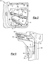
- FIG. 3 illustrates a perspective view of a vehicle door assembly 10.
- the vehicle door assembly 10 may include an outer panel 12 that is spaced apart from an inner panel 14.
- a first cross member 16 and a second cross member 22 may each extend across the vehicle door assembly.
- the second cross member 22 may be spaced apart from the outer panel 12 by a distance L 1 .
- the outer door panel 12 may define a recessed handle pocket 20 that is configured to receive the front-door LMM assembly 100 or rear-door LMM assembly 102.
- To install the front-door LMM assembly 100 or rear-door LMM assembly 102 one of the assemblies 100, 102 must pass between the outer panel 12 and the second cross member 22, along the directional arrow D.
- the front-door LMM assembly 100 or rear-door LMM assembly 102 may have a width of approximately 140 mm. Whereas the narrowest opening defined by the door assembly 10 e.g., Li, may have a width of 125 mm. The discrepancy between the opening of the door assembly and the front-door LMM assembly 100 or rear-door LMM assembly 102 may be problematic for installing the front-door LMM assembly 100 or rear-door LMM assembly 102 to the recessed handle pocket 20.
- FIG. 4 and Figure 5 each illustrate perspective views of an exemplary multi-function bracket assembly 112 according to one or more embodiments of this disclosure.
- the multi-function bracket assembly 112 includes a guide member 140.
- the guide member 140 may include a channel that is configured to receive and guide a window pane (not illustrated).
- a latch receptacle configured to receive either a front-door latch 106a or a rear-door latch 106b may be comprise of an upper retaining member 142 and a lower retaining member 144.
- a handle-chassis bracket 114 may extend from the guide member 140. In one or more embodiments, the handle-chassis bracket 114 may extend in a direction that is orthogonal to the guide member 140.
- a slider 118 and a compressible member 116 may be coupled to the handle chassis bracket 114.
- the slider 118 may include a first portion 120 and a second portion 122. The first portion 120 of the slider 118 may be configured to carry or support the handle chassis 104a, 104b.
- the compressible member 116 may have a compressed state and an uncompressed state.
- the slider 118 may move along the directional arrow D 1 towards the handle chassis bracket 114.
- force applied to a lower end of the compressible member may rotate the slider and a portion of the compressible member along the rotational arrow R.
- Changing the compressible member 116 from the uncompressed state to the compressed state may decrease the width of the front-door LMM assembly 100 and rear-door LMM assembly 102.
- the compressible member 116 may be formed of a foam such as a polyether foam.
- the compressible member may be one or more springs configured to change between a compressed and uncompressed state.
- One or more protrusions may extend from the handle-chassis bracket 114.
- a protrusion such as a retaining member 141 may extend through an aperture 124 defined by the second portion 122 of the slider 118.
- the retaining member 141 may couple the handle-chassis bracket 114 to the slider 118.
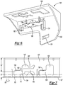
- Figure 6 illustrates a perspective view of the slider 118.
- the second portion 122 of the slider 118 may define an aperture 126 that may be sized to receive one or more protrusions extending from the handle chassis bracket 114.
- Projections such as protrusion engagement teeth 130, 128 may extend into the aperture and be configured to engage one or more protrusions extending from the handle chassis bracket.
- a first set of tunable stops 136 and 137 may extend from the second portion of the slider and be configured to act as a stop for a mating component e.g ., the handle chassis bracket 114.
- a second set of tunable stops 132 and 134 may extend from the second portion of the slider and be configured to engage mating component e.g., the handle chassis bracket 114.
- Figure 7 illustrates a top view of the first portion 120 of the slider 118.
- the first portion 120 of the slider 118 may define a first mounting aperture 146 and a second mounting aperture 158.
- the first mounting aperture 146 may define a first portion 150 and a second portion 154.
- the first portion 150 may be disposed closer to the second portion 122 of the slider 118 than the second portion 154.
- the second portion 154 may be disposed closer to a distal edge of the first portion 120 of the slider 118 than the first portion 150 of the aperture 146.
- the first portion 150 of the first mounting aperture 146 may be spaced apart from the second portion 122 of the slider 118 by a distance L 2 .
- the second portion 154 of the first mounting aperture 146 may be spaced apart from the distal end 157 by a distance L 3 .
- the first portion 120 may include a projection that extends into the first aperture 146.
- the projection may be L-shaped and include a first leg 149 and a second leg 148 that is positioned orthogonally the first leg 149.
- the second mounting aperture 158 may be L-shaped and include a first portion 160 and a second portion 156.
- the front or rear handle chassis may be configured to move between the first portion 150 of the first mounting aperture 146 and the first portion 160 of the second mounting aperture 158 to the second portion 154 of the first mounting aperture 146 and the second portion 156 of the second mounting aperture 158. Moving the handle chassis within the first and second portions of the first and second mounting apertures 146, 158 and along directional arrow D 2 may decrease the width of front-door LMM and rear-door LMM.
- Figure 8 illustrates a perspective view of a portion of the multi-function bracket 112.
- the handle-chassis bracket 114 include one or more protrusions that may be configured to engage the slider 118, or compressible member 116, or both.
- the protrusion or protrusions may include a pair of support walls 164a and 164b that may outwardly extend from the handle-chassis bracket 114.
- the one or more of the support walls 164a and 164b may support a ledge 168 that may extend between the handle-chassis bracket 114 and a flange 166.
- the support walls may be spaced apart by a distance L 4 .
- the flange 166 may be spaced apart from the handle-chassis bracket 114 by a first width W 1 and retain the slider 118, or compressible member 116, or both.
- the slider 118 and the compressible member 116 may be sandwiched between the flange 166 and the handle-chassis bracket 114.
- Figure 9 illustrates a perspective view of the compressible member 116.
- the compressible member 116 may have a rectangular cube shape that has a width of W 2 . When the compressible member changes between the uncompressed state to the compressed state, the width W 2 may change accordingly.
- the compressible member may define an aperture 171 and the aperture may be configured to receive one or more of the protrusions that extend from the handle-chassis bracket 114.
- the aperture 171 may be U-shaped and include a first portion disposed between a second portion 172 and a third portion 174.
- the second portion 172 may have a width W 3 and the third portion 174 may have a width W 4 .
- the second portion 172 and the third portion 174 may each be sized to receive the first support wall 164a and the second support wall 164b.
- the second and third portions 172 and 174 may be configured to engage the first support wall 164a and the second support wall 164b in an interference type fit.
- the aperture 171 may define a length L 5 that may be sized to receive the protrusions, such as the ledge 166, of the handle-chassis bracket 114.
- a method for assembling a multi-function bracket for use in a motor vehicle door comprises the steps of: In a first step, a multi-function bracket is provided comprising an elongated guide member defining a slot configured to guide a window pane, and a handle-chassis bracket extending from the elongated guide member.
- a slider including a first portion and a second portion, wherein the first portion is configured to receive a handle chassis.
- a compressible member is coupled to the second portion of the slider. The compressible member has a compressed state and an uncompressed state.
- the slider and the compressible member are coupled to the chassis bracket.
- a fourth step the slider is translated towards the handle chassis bracket, while changing the compressible member from the uncompressed state to the compressed state.
- a width of the multi-function bracket is decreased.
- force is applied to a lower end of the compressible member, and the slider and a portion of the compressible member rotate, thus decreasing the width of the multi-function bracket.
- one or more protrusions are extending from the handle-chassis bracket to engage the slider.
Applications Claiming Priority (1)
| Application Number | Priority Date | Filing Date | Title |
|---|---|---|---|
| US16/280,438 US11427055B2 (en) | 2019-02-20 | 2019-02-20 | Compressible latch bracket |
Publications (2)
| Publication Number | Publication Date |
|---|---|
| EP3699006A1 true EP3699006A1 (de) | 2020-08-26 |
| EP3699006B1 EP3699006B1 (de) | 2023-09-13 |
Family
ID=69846188
Family Applications (1)
| Application Number | Title | Priority Date | Filing Date |
|---|---|---|---|
| EP20158629.4A Active EP3699006B1 (de) | 2019-02-20 | 2020-02-20 | Komprimierbare verriegelungshalterung |
Country Status (3)
| Country | Link |
|---|---|
| US (1) | US11427055B2 (de) |
| EP (1) | EP3699006B1 (de) |
| CN (1) | CN111591115B (de) |
Families Citing this family (2)
| Publication number | Priority date | Publication date | Assignee | Title |
|---|---|---|---|---|
| US11433752B2 (en) * | 2020-03-11 | 2022-09-06 | Ford Global Technologies, Llc | Liquid diverter assembly and liquid diverting method for a vehicle door |
| DE102021132599A1 (de) * | 2021-01-08 | 2022-07-14 | Magna Closures Inc. | Türmodul |
Citations (4)
| Publication number | Priority date | Publication date | Assignee | Title |
|---|---|---|---|---|
| DE10304203A1 (de) * | 2003-01-27 | 2004-07-29 | Brose Fahrzeugteile Gmbh & Co. Kommanditgesellschaft, Coburg | Anordnung zur Montage im Inneren einer Kfz-Tür |
| US8763308B2 (en) * | 2004-06-23 | 2014-07-01 | Intier Automotive Closures Inc. | Structural door module |
| EP3075585A1 (de) * | 2015-04-01 | 2016-10-05 | Brose Schliesssysteme GmbH & Co. KG | Funktionsanordnung für eine kraftfahrzeugtür |
| FR3052478A1 (fr) * | 2016-06-13 | 2017-12-15 | Peugeot Citroen Automobiles Sa | Poignee et leve-vitre d’ouvrant de vehicule automobile |
Family Cites Families (17)
| Publication number | Priority date | Publication date | Assignee | Title |
|---|---|---|---|---|
| JPH0723656B2 (ja) * | 1987-10-21 | 1995-03-15 | 三井金属鉱業株式会社 | 車両用扉へのアウターハンドル取付装置 |
| DE3921289C1 (de) * | 1989-06-29 | 1991-01-10 | Brose Fahrzeugteile Gmbh & Co Kg, 8630 Coburg, De | |
| US5226259A (en) * | 1990-11-29 | 1993-07-13 | Nissan Motor Co., Ltd. | Automotive door with power window |
| GB2299309B (en) * | 1995-03-28 | 1999-02-17 | Kiekert Ag | Motor vehicle door |
| US5924245A (en) * | 1997-03-18 | 1999-07-20 | General Motors Corporation | Vehicle door hardware |
| US6189267B1 (en) * | 1998-03-02 | 2001-02-20 | General Motors Corporation | Door module with outside door handle |
| US6948691B2 (en) * | 2000-03-17 | 2005-09-27 | Jonathan Manufacturing Corporation | Computer server mounting apparatus |
| DE20309170U1 (de) * | 2003-06-06 | 2004-10-28 | Brose Fahrzeugteile Gmbh & Co. Kg, Coburg | Multifunktionsträger für ein Kraftfahrzeug |
| DE102005025087A1 (de) * | 2005-01-14 | 2006-07-20 | Brose Fahrzeugteile Gmbh & Co. Kommanditgesellschaft, Coburg | Verstellsystem für eine Kraftfahrzeugtür |
| DE202009011302U1 (de) | 2009-08-19 | 2011-01-05 | BROSE SCHLIEßSYSTEME GMBH & CO. KG | Scheibenführung mit Wasserleitsystem |
| US10352072B2 (en) * | 2010-08-23 | 2019-07-16 | Illinois Tool Works Inc. | Snap set door handle and lock knob assembly |
| KR101673338B1 (ko) * | 2014-11-06 | 2016-11-07 | 현대자동차 주식회사 | 차량용 슬라이딩 도어 록킹장치 |
| US10603989B2 (en) | 2015-04-01 | 2020-03-31 | Brose Schliesssysteme Gmbh & Co. Kommanditgesellschaft | Multi function bracket |
| DE202015105205U1 (de) * | 2015-10-02 | 2017-01-09 | BROSE SCHLIEßSYSTEME GMBH & CO. KG | Türmodul für den Einbau in eine Kraftfahrzeugtür |
| DE102016112716A1 (de) * | 2016-07-12 | 2018-01-18 | Dr. Ing. H.C. F. Porsche Aktiengesellschaft | Fahrzeugkomponente |
| US10967714B2 (en) | 2017-09-25 | 2021-04-06 | Ford Global Technologies, Llc | Collapsible side door latch module |
| US11466481B2 (en) * | 2019-02-01 | 2022-10-11 | Nissan North America, Inc. | Vehicle door assembly |
-
2019
- 2019-02-20 US US16/280,438 patent/US11427055B2/en active Active
-
2020
- 2020-02-20 CN CN202010104601.2A patent/CN111591115B/zh active Active
- 2020-02-20 EP EP20158629.4A patent/EP3699006B1/de active Active
Patent Citations (4)
| Publication number | Priority date | Publication date | Assignee | Title |
|---|---|---|---|---|
| DE10304203A1 (de) * | 2003-01-27 | 2004-07-29 | Brose Fahrzeugteile Gmbh & Co. Kommanditgesellschaft, Coburg | Anordnung zur Montage im Inneren einer Kfz-Tür |
| US8763308B2 (en) * | 2004-06-23 | 2014-07-01 | Intier Automotive Closures Inc. | Structural door module |
| EP3075585A1 (de) * | 2015-04-01 | 2016-10-05 | Brose Schliesssysteme GmbH & Co. KG | Funktionsanordnung für eine kraftfahrzeugtür |
| FR3052478A1 (fr) * | 2016-06-13 | 2017-12-15 | Peugeot Citroen Automobiles Sa | Poignee et leve-vitre d’ouvrant de vehicule automobile |
Also Published As
| Publication number | Publication date |
|---|---|
| CN111591115A (zh) | 2020-08-28 |
| US20200262274A1 (en) | 2020-08-20 |
| CN111591115B (zh) | 2023-12-01 |
| EP3699006B1 (de) | 2023-09-13 |
| US11427055B2 (en) | 2022-08-30 |
Similar Documents
| Publication | Publication Date | Title |
|---|---|---|
| EP3699006A1 (de) | Komprimierbare verriegelungshalterung | |
| WO2015072289A1 (ja) | 車載用レーダ設置構造およびフェイシアリテーナ | |
| EP2006134B1 (de) | Fahrzeugtür | |
| JPH08282286A (ja) | 自動車用ドア | |
| KR102443073B1 (ko) | 개폐체의 잠금장치 | |
| US20070125004A1 (en) | Upper reveal molding snap-in 4-way locator insert | |
| EP1049211B1 (de) | Mehrteilige-Verbinder | |
| CN110370900B (zh) | 汽车用车门的窗框构造 | |
| WO2013125524A1 (ja) | 車両用ドアのサッシュ組付構造及び車両用ドアのサッシュ組付方法 | |
| JP2020063658A (ja) | スナップ連結ガイド部材を備える面一装着ガラスデザイン用ウィンドウレギュレータアセンブリ、およびその組立方法 | |
| US6490894B1 (en) | Device for mounting a vehicle door opening control | |
| US5937584A (en) | Integral support for mounting of door module | |
| JP5971526B2 (ja) | 車両用ドアトリムの係止構造 | |
| US4378099A (en) | Outer escutcheon fixing structure for car stereo etc | |
| CN111655079B (zh) | 用于抽屉的框架 | |
| JP6674497B2 (ja) | 自動車用ドアのサッシュ構造 | |
| JP2002307952A (ja) | ドアウエザストリップの取付構造 | |
| JP2000247151A (ja) | グラスラン | |
| CN113891829B (zh) | 车辆用空气动力部件和车辆 | |
| US9358935B2 (en) | Roof drip molding attachment | |
| JP4462974B2 (ja) | ピラーガーニッシュ組付構造 | |
| JP6308872B2 (ja) | 保持装置 | |
| EP1826046A2 (de) | Trägerplatte mit Verkleidungsaufnahmen | |
| JP3867885B2 (ja) | 車両用ドアにおけるガラスサポート構造 | |
| KR100536390B1 (ko) | 슬라이딩 도어용 어퍼 레일의 오버슬램범퍼 장착 구조 |
Legal Events
| Date | Code | Title | Description |
|---|---|---|---|
| PUAI | Public reference made under article 153(3) epc to a published international application that has entered the european phase |
Free format text: ORIGINAL CODE: 0009012 |
|
| STAA | Information on the status of an ep patent application or granted ep patent |
Free format text: STATUS: THE APPLICATION HAS BEEN PUBLISHED |
|
| AK | Designated contracting states |
Kind code of ref document: A1 Designated state(s): AL AT BE BG CH CY CZ DE DK EE ES FI FR GB GR HR HU IE IS IT LI LT LU LV MC MK MT NL NO PL PT RO RS SE SI SK SM TR |
|
| AX | Request for extension of the european patent |
Extension state: BA ME |
|
| STAA | Information on the status of an ep patent application or granted ep patent |
Free format text: STATUS: REQUEST FOR EXAMINATION WAS MADE |
|
| 17P | Request for examination filed |
Effective date: 20210226 |
|
| RBV | Designated contracting states (corrected) |
Designated state(s): AL AT BE BG CH CY CZ DE DK EE ES FI FR GB GR HR HU IE IS IT LI LT LU LV MC MK MT NL NO PL PT RO RS SE SI SK SM TR |
|
| STAA | Information on the status of an ep patent application or granted ep patent |
Free format text: STATUS: EXAMINATION IS IN PROGRESS |
|
| 17Q | First examination report despatched |
Effective date: 20210525 |
|
| GRAP | Despatch of communication of intention to grant a patent |
Free format text: ORIGINAL CODE: EPIDOSNIGR1 |
|
| STAA | Information on the status of an ep patent application or granted ep patent |
Free format text: STATUS: GRANT OF PATENT IS INTENDED |
|
| INTG | Intention to grant announced |
Effective date: 20220929 |
|
| GRAJ | Information related to disapproval of communication of intention to grant by the applicant or resumption of examination proceedings by the epo deleted |
Free format text: ORIGINAL CODE: EPIDOSDIGR1 |
|
| STAA | Information on the status of an ep patent application or granted ep patent |
Free format text: STATUS: EXAMINATION IS IN PROGRESS |
|
| INTC | Intention to grant announced (deleted) | ||
| GRAP | Despatch of communication of intention to grant a patent |
Free format text: ORIGINAL CODE: EPIDOSNIGR1 |
|
| STAA | Information on the status of an ep patent application or granted ep patent |
Free format text: STATUS: GRANT OF PATENT IS INTENDED |
|
| INTG | Intention to grant announced |
Effective date: 20230323 |
|
| GRAS | Grant fee paid |
Free format text: ORIGINAL CODE: EPIDOSNIGR3 |
|
| GRAA | (expected) grant |
Free format text: ORIGINAL CODE: 0009210 |
|
| STAA | Information on the status of an ep patent application or granted ep patent |
Free format text: STATUS: THE PATENT HAS BEEN GRANTED |
|
| AK | Designated contracting states |
Kind code of ref document: B1 Designated state(s): AL AT BE BG CH CY CZ DE DK EE ES FI FR GB GR HR HU IE IS IT LI LT LU LV MC MK MT NL NO PL PT RO RS SE SI SK SM TR |
|
| REG | Reference to a national code |
Ref country code: CH Ref legal event code: EP |
|
| REG | Reference to a national code |
Ref country code: DE Ref legal event code: R096 Ref document number: 602020017482 Country of ref document: DE |
|
| REG | Reference to a national code |
Ref country code: IE Ref legal event code: FG4D |
|
| REG | Reference to a national code |
Ref country code: LT Ref legal event code: MG9D |
|
| REG | Reference to a national code |
Ref country code: NL Ref legal event code: MP Effective date: 20230913 |
|
| PG25 | Lapsed in a contracting state [announced via postgrant information from national office to epo] |
Ref country code: GR Free format text: LAPSE BECAUSE OF FAILURE TO SUBMIT A TRANSLATION OF THE DESCRIPTION OR TO PAY THE FEE WITHIN THE PRESCRIBED TIME-LIMIT Effective date: 20231214 |
|
| PG25 | Lapsed in a contracting state [announced via postgrant information from national office to epo] |
Ref country code: SE Free format text: LAPSE BECAUSE OF FAILURE TO SUBMIT A TRANSLATION OF THE DESCRIPTION OR TO PAY THE FEE WITHIN THE PRESCRIBED TIME-LIMIT Effective date: 20230913 Ref country code: RS Free format text: LAPSE BECAUSE OF FAILURE TO SUBMIT A TRANSLATION OF THE DESCRIPTION OR TO PAY THE FEE WITHIN THE PRESCRIBED TIME-LIMIT Effective date: 20230913 Ref country code: NO Free format text: LAPSE BECAUSE OF FAILURE TO SUBMIT A TRANSLATION OF THE DESCRIPTION OR TO PAY THE FEE WITHIN THE PRESCRIBED TIME-LIMIT Effective date: 20231213 Ref country code: LV Free format text: LAPSE BECAUSE OF FAILURE TO SUBMIT A TRANSLATION OF THE DESCRIPTION OR TO PAY THE FEE WITHIN THE PRESCRIBED TIME-LIMIT Effective date: 20230913 Ref country code: LT Free format text: LAPSE BECAUSE OF FAILURE TO SUBMIT A TRANSLATION OF THE DESCRIPTION OR TO PAY THE FEE WITHIN THE PRESCRIBED TIME-LIMIT Effective date: 20230913 Ref country code: HR Free format text: LAPSE BECAUSE OF FAILURE TO SUBMIT A TRANSLATION OF THE DESCRIPTION OR TO PAY THE FEE WITHIN THE PRESCRIBED TIME-LIMIT Effective date: 20230913 Ref country code: GR Free format text: LAPSE BECAUSE OF FAILURE TO SUBMIT A TRANSLATION OF THE DESCRIPTION OR TO PAY THE FEE WITHIN THE PRESCRIBED TIME-LIMIT Effective date: 20231214 Ref country code: FI Free format text: LAPSE BECAUSE OF FAILURE TO SUBMIT A TRANSLATION OF THE DESCRIPTION OR TO PAY THE FEE WITHIN THE PRESCRIBED TIME-LIMIT Effective date: 20230913 |
|
| PGFP | Annual fee paid to national office [announced via postgrant information from national office to epo] |
Ref country code: FR Payment date: 20231229 Year of fee payment: 5 |
|
| REG | Reference to a national code |
Ref country code: AT Ref legal event code: MK05 Ref document number: 1610921 Country of ref document: AT Kind code of ref document: T Effective date: 20230913 |
|
| PG25 | Lapsed in a contracting state [announced via postgrant information from national office to epo] |
Ref country code: NL Free format text: LAPSE BECAUSE OF FAILURE TO SUBMIT A TRANSLATION OF THE DESCRIPTION OR TO PAY THE FEE WITHIN THE PRESCRIBED TIME-LIMIT Effective date: 20230913 |
|
| PG25 | Lapsed in a contracting state [announced via postgrant information from national office to epo] |
Ref country code: IS Free format text: LAPSE BECAUSE OF FAILURE TO SUBMIT A TRANSLATION OF THE DESCRIPTION OR TO PAY THE FEE WITHIN THE PRESCRIBED TIME-LIMIT Effective date: 20240113 |
|
| PG25 | Lapsed in a contracting state [announced via postgrant information from national office to epo] |
Ref country code: AT Free format text: LAPSE BECAUSE OF FAILURE TO SUBMIT A TRANSLATION OF THE DESCRIPTION OR TO PAY THE FEE WITHIN THE PRESCRIBED TIME-LIMIT Effective date: 20230913 |