WO2015072289A1 - 車載用レーダ設置構造およびフェイシアリテーナ - Google Patents
車載用レーダ設置構造およびフェイシアリテーナ Download PDFInfo
- Publication number
- WO2015072289A1 WO2015072289A1 PCT/JP2014/077840 JP2014077840W WO2015072289A1 WO 2015072289 A1 WO2015072289 A1 WO 2015072289A1 JP 2014077840 W JP2014077840 W JP 2014077840W WO 2015072289 A1 WO2015072289 A1 WO 2015072289A1
- Authority
- WO
- WIPO (PCT)
- Prior art keywords
- radar
- main body
- vehicle
- fascia
- transmission
- Prior art date
Links
Images


Classifications
-
- G—PHYSICS
- G01—MEASURING; TESTING
- G01S—RADIO DIRECTION-FINDING; RADIO NAVIGATION; DETERMINING DISTANCE OR VELOCITY BY USE OF RADIO WAVES; LOCATING OR PRESENCE-DETECTING BY USE OF THE REFLECTION OR RERADIATION OF RADIO WAVES; ANALOGOUS ARRANGEMENTS USING OTHER WAVES
- G01S13/00—Systems using the reflection or reradiation of radio waves, e.g. radar systems; Analogous systems using reflection or reradiation of waves whose nature or wavelength is irrelevant or unspecified
- G01S13/88—Radar or analogous systems specially adapted for specific applications
- G01S13/93—Radar or analogous systems specially adapted for specific applications for anti-collision purposes
- G01S13/931—Radar or analogous systems specially adapted for specific applications for anti-collision purposes of land vehicles
-
- B—PERFORMING OPERATIONS; TRANSPORTING
- B60—VEHICLES IN GENERAL
- B60R—VEHICLES, VEHICLE FITTINGS, OR VEHICLE PARTS, NOT OTHERWISE PROVIDED FOR
- B60R19/00—Wheel guards; Radiator guards, e.g. grilles; Obstruction removers; Fittings damping bouncing force in collisions
- B60R19/02—Bumpers, i.e. impact receiving or absorbing members for protecting vehicles or fending off blows from other vehicles or objects
- B60R19/48—Bumpers, i.e. impact receiving or absorbing members for protecting vehicles or fending off blows from other vehicles or objects combined with, or convertible into, other devices or objects, e.g. bumpers combined with road brushes, bumpers convertible into beds
- B60R19/483—Bumpers, i.e. impact receiving or absorbing members for protecting vehicles or fending off blows from other vehicles or objects combined with, or convertible into, other devices or objects, e.g. bumpers combined with road brushes, bumpers convertible into beds with obstacle sensors of electric or electronic type
-
- B—PERFORMING OPERATIONS; TRANSPORTING
- B60—VEHICLES IN GENERAL
- B60R—VEHICLES, VEHICLE FITTINGS, OR VEHICLE PARTS, NOT OTHERWISE PROVIDED FOR
- B60R19/00—Wheel guards; Radiator guards, e.g. grilles; Obstruction removers; Fittings damping bouncing force in collisions
- B60R19/02—Bumpers, i.e. impact receiving or absorbing members for protecting vehicles or fending off blows from other vehicles or objects
- B60R19/18—Bumpers, i.e. impact receiving or absorbing members for protecting vehicles or fending off blows from other vehicles or objects characterised by the cross-section; Means within the bumper to absorb impact
- B60R2019/1886—Bumper fascias and fastening means therefor
-
- G—PHYSICS
- G01—MEASURING; TESTING
- G01S—RADIO DIRECTION-FINDING; RADIO NAVIGATION; DETERMINING DISTANCE OR VELOCITY BY USE OF RADIO WAVES; LOCATING OR PRESENCE-DETECTING BY USE OF THE REFLECTION OR RERADIATION OF RADIO WAVES; ANALOGOUS ARRANGEMENTS USING OTHER WAVES
- G01S13/00—Systems using the reflection or reradiation of radio waves, e.g. radar systems; Analogous systems using reflection or reradiation of waves whose nature or wavelength is irrelevant or unspecified
- G01S13/88—Radar or analogous systems specially adapted for specific applications
- G01S13/93—Radar or analogous systems specially adapted for specific applications for anti-collision purposes
- G01S13/931—Radar or analogous systems specially adapted for specific applications for anti-collision purposes of land vehicles
- G01S2013/9327—Sensor installation details
- G01S2013/93271—Sensor installation details in the front of the vehicles
-
- G—PHYSICS
- G01—MEASURING; TESTING
- G01S—RADIO DIRECTION-FINDING; RADIO NAVIGATION; DETERMINING DISTANCE OR VELOCITY BY USE OF RADIO WAVES; LOCATING OR PRESENCE-DETECTING BY USE OF THE REFLECTION OR RERADIATION OF RADIO WAVES; ANALOGOUS ARRANGEMENTS USING OTHER WAVES
- G01S13/00—Systems using the reflection or reradiation of radio waves, e.g. radar systems; Analogous systems using reflection or reradiation of waves whose nature or wavelength is irrelevant or unspecified
- G01S13/88—Radar or analogous systems specially adapted for specific applications
- G01S13/93—Radar or analogous systems specially adapted for specific applications for anti-collision purposes
- G01S13/931—Radar or analogous systems specially adapted for specific applications for anti-collision purposes of land vehicles
- G01S2013/9327—Sensor installation details
- G01S2013/93272—Sensor installation details in the back of the vehicles
-
- G—PHYSICS
- G01—MEASURING; TESTING
- G01S—RADIO DIRECTION-FINDING; RADIO NAVIGATION; DETERMINING DISTANCE OR VELOCITY BY USE OF RADIO WAVES; LOCATING OR PRESENCE-DETECTING BY USE OF THE REFLECTION OR RERADIATION OF RADIO WAVES; ANALOGOUS ARRANGEMENTS USING OTHER WAVES
- G01S13/00—Systems using the reflection or reradiation of radio waves, e.g. radar systems; Analogous systems using reflection or reradiation of waves whose nature or wavelength is irrelevant or unspecified
- G01S13/88—Radar or analogous systems specially adapted for specific applications
- G01S13/93—Radar or analogous systems specially adapted for specific applications for anti-collision purposes
- G01S13/931—Radar or analogous systems specially adapted for specific applications for anti-collision purposes of land vehicles
- G01S2013/9327—Sensor installation details
- G01S2013/93274—Sensor installation details on the side of the vehicles
-
- G—PHYSICS
- G01—MEASURING; TESTING
- G01S—RADIO DIRECTION-FINDING; RADIO NAVIGATION; DETERMINING DISTANCE OR VELOCITY BY USE OF RADIO WAVES; LOCATING OR PRESENCE-DETECTING BY USE OF THE REFLECTION OR RERADIATION OF RADIO WAVES; ANALOGOUS ARRANGEMENTS USING OTHER WAVES
- G01S13/00—Systems using the reflection or reradiation of radio waves, e.g. radar systems; Analogous systems using reflection or reradiation of waves whose nature or wavelength is irrelevant or unspecified
- G01S13/88—Radar or analogous systems specially adapted for specific applications
- G01S13/93—Radar or analogous systems specially adapted for specific applications for anti-collision purposes
- G01S13/931—Radar or analogous systems specially adapted for specific applications for anti-collision purposes of land vehicles
- G01S2013/9327—Sensor installation details
- G01S2013/93275—Sensor installation details in the bumper area
-
- G—PHYSICS
- G01—MEASURING; TESTING
- G01S—RADIO DIRECTION-FINDING; RADIO NAVIGATION; DETERMINING DISTANCE OR VELOCITY BY USE OF RADIO WAVES; LOCATING OR PRESENCE-DETECTING BY USE OF THE REFLECTION OR RERADIATION OF RADIO WAVES; ANALOGOUS ARRANGEMENTS USING OTHER WAVES
- G01S7/00—Details of systems according to groups G01S13/00, G01S15/00, G01S17/00
- G01S7/02—Details of systems according to groups G01S13/00, G01S15/00, G01S17/00 of systems according to group G01S13/00
- G01S7/027—Constructional details of housings, e.g. form, type, material or ruggedness
Definitions
- the present invention relates to an in-vehicle radar installation structure in which a radar main body is installed in the vicinity of a bumper of a vehicle, and a fascia retainer for attaching a bumper fascia that is an exterior part of the bumper to the vehicle main body.
- the in-vehicle radar plays a role of assisting a lane change and a collision avoidance brake by measuring the distance and direction with other vehicles and obstacles.
- the in-vehicle radar is also used to give a predetermined warning to the driver and to control various in-vehicle devices such as a seat belt and an air bag.
- Such a vehicle-mounted radar is installed using a radar bracket or the like in a place where it cannot be visually recognized from the outside such as the inside of an exterior part at the front or rear of the vehicle (for example, Patent Document 1).
- the present invention provides an in-vehicle radar installation structure and a fascia retainer that can assemble a radar main body to a vehicle with a simple structure and can contribute to stabilization of radar performance. It is an object.
- a typical configuration of an on-vehicle radar installation structure is a flat three-dimensional body having a transmission / reception surface that is provided on one surface and transmits and receives radio waves.
- a fascia retainer that attaches a bumper fascia, which is an exterior part of a bumper at the front of the vehicle or the rear of the vehicle, to the vehicle body.
- a radar installation part having a recessed shape into which the radar main body is fitted.
- the radar installation portion of the radar main body is provided integrally with the fascia retainer. Therefore, the structure is simpler than before, and the number of assembling steps can be reduced. Further, since the fascia retainer is directly fixed to the vehicle main body and hardly vibrates, the influence of the vibration on the radar performance can be suppressed by providing the fascia retainer with the radar installation part. Therefore, in the above configuration, the radar performance of the radar main body can be stabilized.
- the bumper fascia includes a front portion extending in the vehicle width direction along the front or rear surface of the vehicle body, and a side portion extending along the side surface of the vehicle body from both ends of the front portion. You may have the elongate shape extended in the vehicle front-back direction along the upper edge of a side part. With this configuration, the vicinity of the upper edge of the bumper fascia is fixed to the vehicle by the fascia retainer, and the vibration of the bumper fascia can be more suitably suppressed. Further, by suppressing the vibration of the bumper fascia, the relative shaking between the radar main body and the bumper fascia hardly occurs, and the radar performance of the radar main body can be further stabilized.
- the above radar installation section may be provided in the vicinity of the fixed section.
- the fixing portion which is a fixing point to the vehicle main body, is a portion where the vibration of the member is particularly difficult to occur.
- the radar installation unit may include one or more supports that support the radar main body so that the radar main body does not move by contacting the side surface of the radar main body or the edge of the transmission / reception surface.
- the radar installation part is configured to be supported by the support so that the radar main body does not move.
- the above support may include a claw for pressing the side surface of the radar main body or the edge of the transmission / reception surface.
- the support may include a bridge portion that is spanned on both sides of the radar main body and presses the edge of the transmission / reception surface. According to these claws and bridges, it is possible to realize a support body in which interference with radio waves from the radar main body is suppressed.
- the above radar installation section is provided at a predetermined position on the bottom surface that is in contact with the back surface, which is the opposite surface of the radar main body to the transmitting and receiving surface, and the insertion port where the radar main body is inserted in the direction parallel to the transmitting and receiving surface. You may have a slope guided to the back of the insertion direction of a mouth. Providing these insertion openings and slopes makes it easier to install the radar body in the radar installation section.
- the on-vehicle radar installation structure may further include a case for housing the radar main body, and the radar main body may be fitted into the radar installation section via the case.
- the radar main body can be effectively assembled to the radar installation part even through a predetermined case.
- the case may be assembled to the radar installation part using screws or a predetermined hook.
- the above case may have one or more supports that support the radar main body so that the radar main body does not move by contacting the side surface of the radar main body or the edge of the transmission / reception surface.
- the case can support the case so that the radar main body does not move.
- the radar main body can be installed in a state where most of the transmission / reception surface of the radar main body is opened from the case, except at the place where the support is in contact. Accordingly, since the number of parts that can interfere with radio waves is reduced, the radar main body can sufficiently exhibit its radar performance.
- the above support may include a claw for pressing the side surface of the radar main body or the edge of the transmission / reception surface.
- the support may include a bridge portion that is spanned on both sides of the radar main body and presses the edge of the transmission / reception surface. According to these claws and bridges, it is possible to realize a support body in which interference with radio waves from the radar main body is suppressed.
- the above case is provided at a predetermined position on the bottom surface in contact with the back surface, which is the surface opposite to the transmission / reception surface of the radar main body, and the insertion port through which the radar main body is inserted in the direction parallel to the transmission / reception surface. You may have a slope guided to the back of an insertion direction. Providing these insertion openings and slopes makes it easier to install the radar body in the radar installation section.
- a representative configuration of a fascia retainer according to the present invention is a fascia retainer for attaching a bumper fascia, which is an exterior part of a bumper at the front of the vehicle or the rear of the vehicle, to the vehicle body.
- the radar installation part of the radar body is integrated. Therefore, by using this fascia retainer, there is no need to use a separate radar bracket. Therefore, it is possible to simplify the structure of the vehicle and reduce the number of assembling steps as compared with the conventional case. Further, since the fascia retainer is directly fixed to the vehicle main body and hardly vibrates, the influence of the vibration on the radar performance can be suppressed by installing the radar main body on the fascia retainer. Therefore, with the fascia retainer, the radar performance of the radar main body can be stabilized.
- the fascia retainer may have a long shape extending in the vehicle front-rear direction along the upper edge of the side surface portion extending along the side surface of the vehicle body of the bumper fascia.
- the radar installation unit may be provided in the vicinity of the fixed unit.
- an on-vehicle radar installation structure and a fascia retainer that can assemble a radar main body to a vehicle with a simple structure and can contribute to stabilization of radar performance.
- FIG. 3 is an enlarged view of the vicinity of a radar main body in the fascia retainer of FIG.
- FIG. 4 is a cross-sectional view taken along the line AA in FIG.
- FIG. 7 is a cross-sectional view taken along the line BB in FIG.
- Transmission / reception surface 131 ... Back surface of radar main body, 132 ... Connector, 134 ... Claw, 136 ... Bridge part, 138 ... Bottom surface, 140 ... Insertion port, 142 ... Projection part, 144, 145 ... Slope, 146 ... Notch part, 148... Wiring cord, 150... Fixed portion, 200 mm... Case, 204 ⁇ ⁇ ⁇ ... Radar installation part, 206 ... Hook, 208 ... Screw, 210 ... Screw hole, 212 ... Bottom, 214 ... Insertion port, 216,218 ... Slope, 220 ... Nail, 222 ... Bridge part, 224 ... Notch, 226 mm ... Projection
- FIG. 1 is a diagram illustrating a vehicle to which an in-vehicle radar installation structure 100 according to an embodiment of the present invention is applied.
- the on-vehicle radar 102 illustrated in FIG. 1 measures the distance and position with other vehicles and obstacles by transmitting and receiving radio waves.
- a plurality of in-vehicle radars 102 are installed near the inside of the rear bumper 104 at the rear of the vehicle or near the inside of the front bumper 106 at the front of the vehicle.
- a total of two are installed on both ends in the vehicle width direction on the rear bumper 104 side.
- the in-vehicle radar 102 installed on the left side of the rear bumper 104 will be described as an example.
- FIG. 2 is a diagram exemplarily showing the in-vehicle radar 102 of FIG.
- FIG. 2A is a diagram illustrating the rear bumper 104 of FIG. 1 as viewed from the left side of the vehicle.
- the rear bumper 104 includes a bumper fascia 108 that is an exterior part.
- the bumper fascia 108 includes a front portion 112 extending in the vehicle width direction along the rear surface of the vehicle main body 110, and side surfaces extending along the side surfaces of the vehicle main body 110 from both ends of the front portion 112. Part 114.
- the bumper fascia 118 of the front bumper 106 on the front side of the vehicle is composed of a front portion along the front surface of the vehicle main body and a side portion along the side surface of the vehicle main body.
- FIG. 2A is a diagram in which the bumper fascia 108 of FIG. 2A is removed from the vehicle main body 110.
- the fascia retainer 120 illustrated in FIG. 2B is a part that supports the bumper fascia 108.
- the radar main body 122 is installed on the vehicle main body using a dedicated radar bracket in the conventional configuration, but is installed in the fascia retainer 120. That is, in this embodiment, the function as a radar bracket is added to the fascia retainer 120 to reduce the number of parts and the number of installation steps.
- the fascia retainer 120 has a long shape extending in the vehicle front-rear direction along the upper edge 124 of the side surface portion 114 of the bumper fascia 108 and is assembled to a side panel 126 constituting the side surface of the vehicle main body 110. Yes.
- the bumper fascia 108 in FIG. 2A is connected to the fascia retainer 120 by an inner structure of the upper edge 124 by a claw structure or a clip, and is assembled to the vehicle body 110 via the fascia retainer 120.
- the fascia retainer 120 fixes the bumper fascia 108 (see FIG. 2A), particularly near the upper edge 124, to the vehicle body 110.
- the vibration of the bumper fascia 108 is more preferably suppressed in the vicinity of the fascia retainer 120. Therefore, in the vicinity of the fascia retainer 120, the radar body 122 and the bumper fascia 108 are less likely to be relatively shaken, and the radar performance of the radar body 122 can be further stabilized.
- FIG. 3 is an enlarged view of the vicinity of the radar main body 122 in the fascia retainer 120 of FIG.
- the fascia retainer 120 is provided with a radar installation portion 128, and the radar main body 122 is configured to be fitted into the radar installation portion 128.
- the radar main body 122 is installed with the transmission / reception surface 130 that transmits and receives radio waves facing outward in the vehicle width direction.
- FIG. 3 (b) is an exploded view of FIG. 3 (a).
- the radar main body 122 described above is configured as a flat solid, and the radar main body 122 is preferably a flat rectangular parallelepiped as illustrated in FIG. 3B.
- the flat three-dimensional radar main body 122 is provided with a transmission / reception surface 130 on at least one plane.
- the transmission / reception surface 130 is one of two surfaces having the largest area in a flat rectangular parallelepiped.
- the radar main body 122 has a connector 132.
- the connector 132 is electrically connected to the vehicle main body 110 side (see FIG. 1), and transmits and receives radio waves toward the target.
- the radar installation unit 128 has a recessed shape so as to fit the radar main body 122 so that the radar main body 122 can be fitted.
- the radar installation unit 128 is provided with a plurality of supports that support the embedded radar main body 122 so as not to move. This support is realized as a claw 134 and a bridge portion 136.
- Two claws 134 are provided on both sides of the radar main body 122.
- the claw 134 protrudes toward the center of the transmission / reception surface 130 of the radar main body 122 and contacts and supports the edge of the transmission / reception surface 130.
- the bridge portion 136 is bridged on both sides of the radar main body 122 in the vicinity of the edge on the connector 132 side of the transmission / reception surface 130 and presses the edge on the connector 132 side of the transmission / reception surface 130.
- the claw 134 and the bridge portion 136 described above are configured to support the edge rather than the center side of the transmission / reception surface 130, and interference with radio waves transmitted and received by the transmission / reception surface 130 is suppressed.
- the radar installation unit 128 opens the large part of the transmission / reception surface 130 of the radar main body 122 by the claws 134 and the bridge unit 136 so that the radar main body 122 sufficiently exhibits its radar performance, while the radar main body 122 It can be fully supported not to fall off.
- a support body it is realizable also as a rib etc. which support the side surface of the radar main body 122 besides.
- FIG. 4 is a cross-sectional view taken along line AA in FIG.
- an insertion port 140 is formed between the bridge unit 136 and the bottom surface 138 of the radar installation unit 128.
- the radar main body 122 is inserted from the insertion port 140 in the direction parallel to the transmission / reception surface 130.
- the size of the opening 140 specifically, the distance from the bridge portion 136 to the bottom surface 138 immediately below the opening 140 is slightly narrower than the thickness of the radar main body 122 so that the radar main body 122 can be held between them.
- a protrusion 142 that fits into the radar main body 122 that has been inserted is provided on the bottom surface 138 side of the bridge portion 136 so that the inserted radar main body 122 does not fall off.
- the radar installation portion 128 has the opening 140 set to the above size and the projection 142 projecting toward the radar main body 122, the radar main body 122 can be inserted without any problem. Therefore, two slopes 144 and 145 are provided on the bottom surface 138. These slopes 144 and 145 are for guiding the radar main body 122 to the back of the insertion port 140, and the slope 144 is provided at the end of the bottom surface 138 on the entrance side, and the slope 145 is located below the bridge portion 136.
- the bottom surface 138 is provided at a location where the height is raised.
- the bottom surface 138 comes into contact with the back surface 131 that is the back side of the transmission / reception surface 130 of the radar main body portion 122, and the back surface 131 slides on the bottom surface 138.
- the radar main body 122 rides on a slope 145 provided near the lower portion of the bridge portion 136, so that the radar main body 122 assumes an oblique posture so as to avoid the protrusion 142.
- a slope 144 is provided at the end of the bottom surface 138 on the entrance side so that the inclined posture can be suitably taken so as not to interfere with the inclined radar main body 122. In this manner, in the radar installation unit 128, the slopes 144 and 145 are provided, so that the radar main body 122 can be smoothly inserted and held by the bridge unit 136 and the bottom unit 138.
- the bridge portion 136 is provided with a notch 146 so that the connector 132 of the inserted radar main body 122 is exposed.
- the wiring cords 148 can be preferably attached to and detached from the connector 132 even after the radar main body 122 is fitted into the radar installation part 128.
- the radar installation part 128 is provided in the vicinity of the fixed part 150 of the fascia retainer 120 so that the radar main body 122 can stably exhibit its radar performance.
- the fixing part 150 is a part that is fixed to the side panel 126 (FIG. 2B) using bolts, clips, or the like.
- the vicinity of the fixed portion 150 is a portion that is not particularly easily affected by the vibration of the bumper fascia 108 in the fascia retainer 120 during traveling of the vehicle. Therefore, by providing the radar installation part 128 in the vicinity, the influence on the radar main body 122 due to vibration can be suppressed.
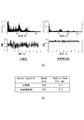
- FIG. 5 is a diagram in which vibrations received by the radar main bodies of the in-vehicle radar installation structure 100 and the comparative example 10 of the present embodiment during traveling of the vehicle are measured.
- the radar main body 12 is positioned at the center of the side panel 126 inside the side panel 114 of the bumper fascia 108 (see FIG. 2A). In this configuration, the radar bracket 14 is assembled in the vicinity.
- the vibration received by the radar main body when the vehicle travels at 120 km is measured.
- the upper graph is the result of spectral analysis in which the horizontal axis represents the frequency and the vertical axis represents the value relating to the vibration energy at that frequency.
- the vertical axis represents the vibration output value at that time.
- the result of each graph is summarized in the table of FIG.
- the peak peak value (difference between the maximum value and the minimum value) of the amplitude is about ⁇ 0.5 mm in the present embodiment and about ⁇ 1.5 mm in the comparative example. In this embodiment, the peak peak value is suppressed to about 1/3 compared to the comparative example.
- the radar installation portion of the radar main body is integrated near the fixed portion of the fascia retainer.
- the structure is simpler than that of the comparative example, and the number of assembling steps can be reduced. Therefore, the configuration is very effective both in terms of performance and cost.
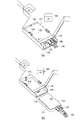
- FIG. 6 is a diagram illustrating a modification of the in-vehicle radar 102 illustrated in FIG.
- FIG. 6A is a diagram illustrating an in-vehicle radar 200 which is a modified example, corresponding to FIG. 3B.
- the in-vehicle radar 200 illustrated in FIG. 6A includes a case 202 that accommodates the radar main body 122, and the radar main body 122 is assembled to the radar installation unit 204 via the case 202.
- the configuration is different from that of the in-vehicle radar 102.
- components already described with reference to FIGS. 1 to 5 are denoted by the same reference numerals, and description thereof is omitted.
- the in-vehicle radar device 200 also measures the distance and position with other vehicles and obstacles by transmitting and receiving radio waves, similarly to the in-vehicle radar 102 in FIG.
- a plurality of in-vehicle radars 200 can be installed near the inside of the rear bumper 104 (see FIG. 1) at the rear of the vehicle or near the inside of the front bumper 106 at the front of the vehicle.
- the in-vehicle radar 200 is assumed to be installed on the left side of the rear bumper 104 in the same manner as the in-vehicle radar 102 in FIG. 1, and is assembled on the vehicle main body 110 inside the side surface portion 114 of the bumper fascia 108. ing.
- the radar installation unit 204 is provided in the fascia retainer 120, and has a structure in which the radar main body 122 is fitted through a case.
- FIG. 3B is an exploded view of the in-vehicle radar shown in FIG. As illustrated in FIG. 3B, the radar installation unit 204 is different from the radar installation unit 128 in which the radar main body 122 illustrated in FIG. 3B is directly fitted, and the case 202 containing the radar main body 122 is inserted. . Therefore, the radar installation unit 204 has a shape that is recessed according to the outer shape of the case 202.
- the radar installation unit 204 is appropriately provided with a part for assembling the case 202, such as a hook 206 for holding the case 202 and a screw hole 210 for fastening the case 202 using a screw 208.
- the case 202 directly supports the radar main body 122 and is fitted into the radar installation unit 204.
- the case 202 is formed using a resin or the like as a material.
- the case 202 is provided with a claw 220 and a bridge portion 222 that are support bodies that support the radar main body 122.
- Two claws 220 are provided on both sides of the radar main body 122 and contact the edges of the transmission / reception surface 130 to support them.
- the bridge portion 222 is bridged on both sides of the radar main body 122 in the vicinity of the edge of the transmission / reception surface 130 on the connector 132 side, and presses the edge of the transmission / reception surface 130 on the connector 132 side.
- These claws 220 and bridge portions 222 are configured to support the edges of the transmission / reception surface 130 instead of the center, and interference with radio waves transmitted and received by the transmission / reception surface 130 is suppressed.
- the case 202 and the radar installation portion 204 allow the radar main body 122 to sufficiently exhibit its radar performance by opening most of the transmission / reception surface 130 of the radar main body 122, while the radar main body 122 It can be fully supported not to fall off.
- a support body it is realizable also as a rib etc. which support the side surface of the radar main body 122 besides.
- the bridge portion 222 is provided with a notch 224 so that the connector 132 of the inserted radar main body 122 is exposed. According to the notch 224, the wiring cord 148 can be preferably attached to and detached from the connector 132 even after the radar main body 122 is stored in the case 202.
- FIG. 7 is a cross-sectional view taken along the line BB in FIG. 6 (b).
- an insertion port 214 is formed between the bridge portion 222 and the bottom surface 212 of the case 202.
- the radar main body 122 is inserted from the insertion port 214 in the direction parallel to the transmission / reception surface 130.
- the size of the insertion opening 214 specifically, the distance from the bridge portion 222 to the bottom surface 212 just below it, is slightly narrower than the thickness of the radar main body 122 so that the radar main body 122 can be gripped between them.
- a projection 226 that fits into the radar main body 122 that has been inserted is provided on the bottom surface 212 side of the bridge portion 222.
- Two slopes 216 and 218 are provided on the bottom surface 212. These slopes 216, 218 are for guiding the radar main body 122 to the back of the insertion port 214, and the slope 216 is provided at the inlet side end of the bottom surface 212, and the slope 218 is below the bridge portion 222.
- the bottom surface 212 is provided at a location where the height is raised.
- the bottom surface 212 comes into contact with the back surface 131 that is the back side of the transmission / reception surface 130 of the radar main body portion 122, and the back surface 131 slides on the bottom surface 212.
- the radar main body 122 rides on a slope 218 provided near the lower portion of the bridge portion 222, and assumes an oblique posture so as to avoid the protruding portion 226.
- a slope 216 is provided at the end of the bottom surface 212 on the entrance side so that the oblique posture can be suitably taken so as not to interfere with the inclined radar main body 122. In this manner, in the case 202, the slopes 216 and 218 are provided, so that the radar main body 122 can be smoothly inserted and held by the bridge portion 222 and the bottom surface 212.
- the radar installation part 204 is provided in the vicinity of the fixed part 150 of the fascia retainer 120 so that the radar main body 122 can stably exhibit its radar performance.
- the fixing part 150 is a part that is fixed to the side panel 126 (FIG. 2B) using bolts, clips, or the like.
- the vicinity of the fixed portion 150 is a portion that is not particularly easily affected by the vibration of the bumper fascia 108 in the fascia retainer 120 during traveling of the vehicle. Therefore, by providing the radar installation part 128 in the vicinity, the influence on the radar main body 122 due to vibration can be suppressed.
- the present invention can be used for an on-vehicle radar installation structure in which a radar main body is installed near a bumper of a vehicle, and a fascia retainer that attaches a bumper fascia that is an exterior part of the bumper to the vehicle main body.
Landscapes
- Engineering & Computer Science (AREA)
- Radar, Positioning & Navigation (AREA)
- Remote Sensing (AREA)
- Physics & Mathematics (AREA)
- Electromagnetism (AREA)
- Computer Networks & Wireless Communication (AREA)
- General Physics & Mathematics (AREA)
- Mechanical Engineering (AREA)
- Radar Systems Or Details Thereof (AREA)
Abstract
Description
図6は、図3に例示した車載用レーダ102の変形例を例示した図である。図6(a)は、図3(b)に対応して、変形例である車載用レーダ200を例示した図である。図6(a)に例示する車載用レーダ200は、レーダ本体122を収容するケース202を備え、このケース202を介してレーダ本体122をレーダ設置部204に組み付けている点において、図3(a)の車載用レーダ102と構成が異なっている。なお、以下では、図1~5を参照して既に説明した構成要素は、同じ符号を付することによってその説明を省略する。
Claims (15)
- 扁平な立体であって、一つの面に設けられて電波の送受信を行う送受信面を有するレーダ本体と、
車両前部または車両後部のバンパの外装部品であるバンパフェイシアを車両本体に取り付けるフェイシアリテーナと、
を備え、
前記フェイシアリテーナは、
前記車両本体に固定される固定部と、
前記レーダ本体の前記送受信面が車両外側へ向くように該レーダ本体がはめ込まれる窪んだ形状を有するレーダ設置部と、
を有することを特徴とする車載用レーダ設置構造。 - 前記バンパフェイシアは、前記車両本体の前面または後面に沿って車幅方向に延びる正面部分と、該正面部分の両端から該車両本体の側面に沿って延びる側面部分とを含み、
前記フェイシアリテーナは、前記バンパフェイシアの前記側面部分の上縁に沿って車両前後方向に延びた長尺な形状を有することを特徴とする請求項1に記載の車載用レーダ設置構造。 - 前記レーダ設置部は、前記固定部の近傍に設けられることを特徴とする請求項1または2に記載の車載用レーダ設置構造。
- 前記レーダ設置部は、前記レーダ本体の側面または前記送受信面の縁に接触して該レーダ本体が動かないようこれを支える1つ以上の支持体を含むことを特徴とする請求項1から3のいずれか1項に記載の車載用レーダ設置構造。
- 前記支持体は、前記レーダ本体の側面または前記送受信面の縁を押さえるツメを含むことを特徴とする請求項4に記載の車載用レーダ設置構造。
- 前記支持体は、前記レーダ本体の両脇に架け渡されて前記送受信面の縁を押さえるブリッジ部を含むことを特徴とする請求項4または5に記載の車載用レーダ設置構造。
- 前記レーダ設置部は、
前記レーダ本体が前記送受信面の平行方向に挿入される挿入口と、
前記レーダ本体の前記送受信面の反対側の面である裏面に接する底面の所定位置に設けられ、該レーダ本体を前記挿入口の挿入方向の奥に案内するスロープを有することを特徴とする請求項1から6のいずれか1項に記載の車載用レーダ設置構造。 - 当該車載用レーダ設置構造はさらに、前記レーダ本体を収容するケースを備え、
前記レーダ本体は、前記ケースを介して前記レーダ設置部にはめ込まれることを特徴とする請求項1から3のいずれか1項に記載の車載用レーダ設置構造。 - 前記ケースは、前記レーダ本体の側面または前記送受信面の縁に接触して該レーダ本体が動かないようこれを支える1つ以上の支持体を有することを特徴とする請求項8に記載の車載用レーダ設置構造。
- 前記支持体は、前記レーダ本体の側面または前記送受信面の縁を押さえるツメを含むことを特徴とする請求項9に記載の車載用レーダ設置構造。
- 前記支持体は、前記レーダ本体の両脇に架け渡されて前記送受信面の縁を押さえるブリッジ部を含むことを特徴とする請求項9または10に記載の車載用レーダ設置構造。
- 前記ケースは、
前記レーダ本体が前記送受信面の平行方向に挿入される挿入口と、
前記レーダ本体の前記送受信面の反対側の面である裏面に接する底面の所定位置に設けられ、該レーダ本体を前記挿入口の挿入方向の奥に案内するスロープを有することを特徴とする請求項8から11のいずれか1項に記載の車載用レーダ設置構造。 - 車両前部または車両後部のバンパの外装部品であるバンパフェイシアを車両本体に取り付けるフェイシアリテーナであって、
前記車両本体に固定される固定部と、
扁平な立体のレーダ本体の送受信面が車両外側へ向くように該レーダ本体がはめ込まれる窪んだ形状を有するレーダ設置部と、
を備えることを特徴とするフェイシアリテーナ。 - 当該フェイシアリテーナは、前記バンパフェイシアの前記車両本体の側面に沿って延びる側面部分の上縁に沿って車両前後方向に延びた長尺な形状を有することを特徴とする請求項13に記載のフェイシアリテーナ。
- 前記レーダ設置部は、前記固定部の近傍に設けられることを特徴とする請求項13または14に記載のフェイシアリテーナ。
Priority Applications (4)
| Application Number | Priority Date | Filing Date | Title |
|---|---|---|---|
| EP14862318.4A EP3070489B1 (en) | 2013-11-14 | 2014-10-20 | Vehicle radar installation structure and fascia retainer |
| JP2015547706A JP6254183B2 (ja) | 2013-11-14 | 2014-10-20 | 車載用レーダ設置構造およびフェイシアリテーナ |
| CN201480062480.2A CN105723235B (zh) | 2013-11-14 | 2014-10-20 | 车载用雷达设置结构和面板固定件 |
| US15/036,674 US9804261B2 (en) | 2013-11-14 | 2014-10-20 | Vehicle radar installation structure and fascia retainer |
Applications Claiming Priority (2)
| Application Number | Priority Date | Filing Date | Title |
|---|---|---|---|
| JP2013-236048 | 2013-11-14 | ||
| JP2013236048 | 2013-11-14 |
Publications (1)
| Publication Number | Publication Date |
|---|---|
| WO2015072289A1 true WO2015072289A1 (ja) | 2015-05-21 |
Family
ID=53057231
Family Applications (1)
| Application Number | Title | Priority Date | Filing Date |
|---|---|---|---|
| PCT/JP2014/077840 WO2015072289A1 (ja) | 2013-11-14 | 2014-10-20 | 車載用レーダ設置構造およびフェイシアリテーナ |
Country Status (5)
| Country | Link |
|---|---|
| US (1) | US9804261B2 (ja) |
| EP (1) | EP3070489B1 (ja) |
| JP (1) | JP6254183B2 (ja) |
| CN (1) | CN105723235B (ja) |
| WO (1) | WO2015072289A1 (ja) |
Cited By (6)
| Publication number | Priority date | Publication date | Assignee | Title |
|---|---|---|---|---|
| RU2660659C1 (ru) * | 2016-05-31 | 2018-07-09 | Мицубиси Дзидося Когио Кабусики Кайся | Монтажная конструкция c радиолокационным устройством |
| JP2020091152A (ja) * | 2018-12-04 | 2020-06-11 | 本田技研工業株式会社 | 検出装置および車両 |
| JP2020101468A (ja) * | 2018-12-24 | 2020-07-02 | ロベルト・ボッシュ・ゲゼルシャフト・ミト・ベシュレンクテル・ハフツングRobert Bosch Gmbh | アダプター |
| JP2020165734A (ja) * | 2019-03-28 | 2020-10-08 | 日野自動車株式会社 | 周辺監視システム |
| CN113567970A (zh) * | 2021-07-23 | 2021-10-29 | 深圳市国天电子股份有限公司 | 一种雷达壳子 |
| US11358536B2 (en) | 2018-12-07 | 2022-06-14 | Honda Motor Co., Ltd. | Detection apparatus |
Families Citing this family (19)
| Publication number | Priority date | Publication date | Assignee | Title |
|---|---|---|---|---|
| JP6202028B2 (ja) * | 2015-03-24 | 2017-09-27 | トヨタ自動車株式会社 | 周辺情報検出センサの配設構造及び自動運転車両 |
| US10144424B2 (en) * | 2015-04-09 | 2018-12-04 | Toyota Jidosha Kabushiki Kaisha | Arrangement structure for vicinity information detection sensor |
| US9956993B1 (en) | 2017-01-20 | 2018-05-01 | Ford Global Technologies, Llc | Vehicle front impact sensor with impact resistant carriage |
| DE202017102515U1 (de) * | 2017-03-17 | 2018-06-26 | Rehau Ag + Co | Elektronikmodulsystem für ein Kraftfahrzeug |
| JP6786560B2 (ja) * | 2018-09-26 | 2020-11-18 | 本田技研工業株式会社 | 車体前部構造 |
| CN109131135B (zh) * | 2018-09-30 | 2021-04-06 | 江苏中路工程技术研究院有限公司 | 一种车载雷达固定装置 |
| JP7155931B2 (ja) * | 2018-11-20 | 2022-10-19 | トヨタ自動車株式会社 | 車両用センサ搭載構造 |
| JP6932119B2 (ja) * | 2018-12-04 | 2021-09-08 | 本田技研工業株式会社 | 検出装置および車両 |
| CN110001562B (zh) * | 2019-05-13 | 2023-10-13 | 重庆平伟汽车零部件有限公司 | 汽车雷达支架插接式安装结构 |
| JP6842511B2 (ja) | 2019-07-31 | 2021-03-17 | 本田技研工業株式会社 | 車体の側部に於けるセンサ取付構造 |
| JP7216343B2 (ja) * | 2020-01-27 | 2023-02-01 | トヨタ自動車株式会社 | 車両用検出センサの搭載構造及びブラケット |
| FR3107486B1 (fr) * | 2020-02-21 | 2022-01-28 | Renault Sas | Ensemble de structure arrière renforcée de véhicule automobile |
| FR3117988B1 (fr) * | 2020-12-23 | 2023-08-25 | Cie Plastic Omnium Se | Pièce de carrosserie de véhicule automobile |
| US11731567B2 (en) * | 2021-01-28 | 2023-08-22 | Nissan North America, Inc. | Sensor assemblies and object detection in vehicles |
| FR3120334B1 (fr) * | 2021-03-03 | 2023-01-20 | Psa Automobiles Sa | Système de fixation d’un module de détection pour véhicule automobile |
| JP2022158504A (ja) * | 2021-04-02 | 2022-10-17 | トヨタ自動車株式会社 | 車両構造 |
| JP2024006105A (ja) * | 2022-06-30 | 2024-01-17 | 株式会社ニフコ | バンパリテーナ及び車両用部品の取付構造 |
| CN115561736B (zh) * | 2022-10-25 | 2023-10-13 | 山东莱恩光电科技股份有限公司 | 一种激光雷达免维护护罩及雷达 |
| CN115902861B (zh) * | 2022-12-21 | 2023-10-31 | 东南大学 | 一种储能电站建设的选址定位勘探辅助设备 |
Citations (3)
| Publication number | Priority date | Publication date | Assignee | Title |
|---|---|---|---|---|
| JP2007030534A (ja) * | 2005-07-22 | 2007-02-08 | Mazda Motor Corp | 衝突検知センサの取付構造 |
| EP2006162A1 (en) * | 2007-06-21 | 2008-12-24 | Chrysler Llc | Vehicle blind spot radar sensor mount |
| JP2010066092A (ja) | 2008-09-10 | 2010-03-25 | Nissan Diesel Motor Co Ltd | 車載レーダのアンテナ軸調整装置 |
Family Cites Families (19)
| Publication number | Priority date | Publication date | Assignee | Title |
|---|---|---|---|---|
| US3794997A (en) | 1971-09-30 | 1974-02-26 | Toyota Motor Co Ltd | Vehicle with apparatus for detecting potential collisions |
| JPS5125079Y2 (ja) * | 1971-09-30 | 1976-06-26 | ||
| DE19719519A1 (de) * | 1997-05-09 | 1998-11-12 | Bosch Gmbh Robert | Anordnung mit einem Modul zum Einbau in einen Stoßfänger eines Kraftfahrzeugs |
| EP1269446B8 (en) * | 2000-02-28 | 2009-12-09 | SMR PATENTS S.à.r.l. | Mounting for proximity radar |
| GB0005312D0 (en) * | 2000-02-28 | 2000-04-26 | Britax Wingard Ltd | Mounting for proximity radar |
| FR2823163B1 (fr) * | 2001-04-04 | 2003-07-04 | Plastic Omnium Cie | Element exterieur de vehicule automobile, integrant un capteur capacitif et piece de carrosserie comportant un tel element exterieur |
| JP4065815B2 (ja) * | 2003-07-15 | 2008-03-26 | 三菱電機株式会社 | 車載用電波レーダ装置 |
| JP4065268B2 (ja) * | 2004-11-15 | 2008-03-19 | アンリツ株式会社 | 車載用アンテナ |
| US7988212B2 (en) * | 2007-01-25 | 2011-08-02 | Ford Motor Company | Vehicle mounting and alignment bracket |
| JP4905372B2 (ja) * | 2007-06-27 | 2012-03-28 | 日産自動車株式会社 | 車両用衝撃センサの取付構造 |
| JP2009287950A (ja) * | 2008-05-27 | 2009-12-10 | Suzuki Motor Corp | レーダー装置の取付構造 |
| DE112009004596B4 (de) | 2009-03-24 | 2014-03-27 | Toyota Jidosha Kabushiki Kaisha | Frontaufbau und Heckaufbau eines Fahrzeugs |
| JP5691019B2 (ja) * | 2010-03-02 | 2015-04-01 | パナソニックIpマネジメント株式会社 | アンテナ装置 |
| JP2011199732A (ja) | 2010-03-23 | 2011-10-06 | Hitachi Cable Ltd | 無線lanシステム、移動端末及び移動端末のipアドレス切替方法 |
| DE202011001928U1 (de) * | 2011-01-25 | 2012-04-30 | Rehau Ag + Co | Haltevorrichtung zur Aufnahme und Befestigung einer Elektronikeinheit hinter einem Verkleidungsteil eines Kraftfahrzeuges sowie ein entsprechendes Verkleidungsteil mit einer Haltevorrichtung |
| US9038876B2 (en) * | 2013-04-08 | 2015-05-26 | Ford Global Technologies, Llc | Radar mounting device |
| TWI486611B (zh) * | 2013-04-18 | 2015-06-01 | Wistron Neweb Corp | 車用雷達系統之雷達裝置 |
| KR101459910B1 (ko) * | 2013-05-28 | 2014-11-07 | 현대자동차주식회사 | 차량용 레이더장치 |
| US9995822B2 (en) * | 2013-06-13 | 2018-06-12 | Continental Automotive Systems, Inc. | Integration of a radar sensor in a vehicle |
-
2014
- 2014-10-20 US US15/036,674 patent/US9804261B2/en active Active
- 2014-10-20 JP JP2015547706A patent/JP6254183B2/ja not_active Expired - Fee Related
- 2014-10-20 CN CN201480062480.2A patent/CN105723235B/zh not_active Expired - Fee Related
- 2014-10-20 WO PCT/JP2014/077840 patent/WO2015072289A1/ja active Application Filing
- 2014-10-20 EP EP14862318.4A patent/EP3070489B1/en active Active
Patent Citations (3)
| Publication number | Priority date | Publication date | Assignee | Title |
|---|---|---|---|---|
| JP2007030534A (ja) * | 2005-07-22 | 2007-02-08 | Mazda Motor Corp | 衝突検知センサの取付構造 |
| EP2006162A1 (en) * | 2007-06-21 | 2008-12-24 | Chrysler Llc | Vehicle blind spot radar sensor mount |
| JP2010066092A (ja) | 2008-09-10 | 2010-03-25 | Nissan Diesel Motor Co Ltd | 車載レーダのアンテナ軸調整装置 |
Non-Patent Citations (1)
| Title |
|---|
| See also references of EP3070489A4 |
Cited By (9)
| Publication number | Priority date | Publication date | Assignee | Title |
|---|---|---|---|---|
| RU2660659C1 (ru) * | 2016-05-31 | 2018-07-09 | Мицубиси Дзидося Когио Кабусики Кайся | Монтажная конструкция c радиолокационным устройством |
| JP2020091152A (ja) * | 2018-12-04 | 2020-06-11 | 本田技研工業株式会社 | 検出装置および車両 |
| US10857952B2 (en) | 2018-12-04 | 2020-12-08 | Honda Motor Co., Ltd. | Detection apparatus and vehicle |
| US11358536B2 (en) | 2018-12-07 | 2022-06-14 | Honda Motor Co., Ltd. | Detection apparatus |
| JP2020101468A (ja) * | 2018-12-24 | 2020-07-02 | ロベルト・ボッシュ・ゲゼルシャフト・ミト・ベシュレンクテル・ハフツングRobert Bosch Gmbh | アダプター |
| JP7288757B2 (ja) | 2018-12-24 | 2023-06-08 | ロベルト・ボッシュ・ゲゼルシャフト・ミト・ベシュレンクテル・ハフツング | アダプター |
| JP2020165734A (ja) * | 2019-03-28 | 2020-10-08 | 日野自動車株式会社 | 周辺監視システム |
| JP7267807B2 (ja) | 2019-03-28 | 2023-05-02 | 日野自動車株式会社 | 周辺監視システム |
| CN113567970A (zh) * | 2021-07-23 | 2021-10-29 | 深圳市国天电子股份有限公司 | 一种雷达壳子 |
Also Published As
| Publication number | Publication date |
|---|---|
| EP3070489B1 (en) | 2020-01-01 |
| US9804261B2 (en) | 2017-10-31 |
| JPWO2015072289A1 (ja) | 2017-03-16 |
| EP3070489A1 (en) | 2016-09-21 |
| JP6254183B2 (ja) | 2017-12-27 |
| CN105723235B (zh) | 2019-03-26 |
| US20160291151A1 (en) | 2016-10-06 |
| CN105723235A (zh) | 2016-06-29 |
| EP3070489A4 (en) | 2017-06-21 |
Similar Documents
| Publication | Publication Date | Title |
|---|---|---|
| JP6254183B2 (ja) | 車載用レーダ設置構造およびフェイシアリテーナ | |
| US7052076B2 (en) | Front side-part structure of vehicle | |
| JP6276872B2 (ja) | 車載用レーダ装置 | |
| JP6146131B2 (ja) | 電子制御ユニットおよび保護ケース | |
| KR20160009859A (ko) | 자동차의 통합형 인사이드 미러 조립체 | |
| US20160139168A1 (en) | Fastening Device for an Electronic Component, in Particular an Acceleration Sensor for Airbag Systems | |
| JP3950233B2 (ja) | インストルメントパネルにおけるワイヤハーネスの固定構造及びインストルメントパネル | |
| JP4871663B2 (ja) | 車両搭載型ドライビングレコーダの取付具 | |
| US11115742B2 (en) | Microphone assembly and microphone arrangement | |
| JP3193264U (ja) | 車載用レーダ装置 | |
| KR200496491Y1 (ko) | 차량용 내비게이션 장착을 위한 결합 구조 | |
| US8864218B2 (en) | Vehicular ceiling assembly and vehicular roof assembly | |
| US11427055B2 (en) | Compressible latch bracket | |
| KR101629831B1 (ko) | 크래쉬패드 체결장치 | |
| JP2010132242A (ja) | 自動車のドア用トリムボード及び自動車のバックドア | |
| JP2008092463A (ja) | 車両用アンテナ内蔵外装品 | |
| US10013016B2 (en) | Method and instruction for attachment of ETC pedal to bracket | |
| KR20090102454A (ko) | 자동차용 거리측정센서의 설치부재와 이를 이용한 설치구조 | |
| US20210380047A1 (en) | On-board bracket for on-board device at vehicle | |
| JP5200689B2 (ja) | 車両のインストルメントパネル部構造 | |
| WO2015045849A1 (ja) | 車載用レーダ装置 | |
| KR101037047B1 (ko) | 자동차용 하이패스 시스템의 안테나 장착구조 | |
| US20050039024A1 (en) | System and method for engine compartment optimization | |
| CN218888708U (zh) | 车载扬声器装置 | |
| JP2009177427A (ja) | 車両接地形アンテナアセンブリ |
Legal Events
| Date | Code | Title | Description |
|---|---|---|---|
| 121 | Ep: the epo has been informed by wipo that ep was designated in this application |
Ref document number: 14862318 Country of ref document: EP Kind code of ref document: A1 |
|
| ENP | Entry into the national phase |
Ref document number: 2015547706 Country of ref document: JP Kind code of ref document: A |
|
| WWE | Wipo information: entry into national phase |
Ref document number: 15036674 Country of ref document: US |
|
| NENP | Non-entry into the national phase |
Ref country code: DE |
|
| REEP | Request for entry into the european phase |
Ref document number: 2014862318 Country of ref document: EP |
|
| WWE | Wipo information: entry into national phase |
Ref document number: 2014862318 Country of ref document: EP |