EP3661640B1 - Verbesserter prozessintensivierter strömungsreaktor - Google Patents
Verbesserter prozessintensivierter strömungsreaktor Download PDFInfo
- Publication number
- EP3661640B1 EP3661640B1 EP18762656.9A EP18762656A EP3661640B1 EP 3661640 B1 EP3661640 B1 EP 3661640B1 EP 18762656 A EP18762656 A EP 18762656A EP 3661640 B1 EP3661640 B1 EP 3661640B1
- Authority
- EP
- European Patent Office
- Prior art keywords
- chamber
- flow reactor
- obstacles
- process fluid
- obstacle
- Prior art date
- Legal status (The legal status is an assumption and is not a legal conclusion. Google has not performed a legal analysis and makes no representation as to the accuracy of the status listed.)
- Active
Links
Images


Classifications
-
- B—PERFORMING OPERATIONS; TRANSPORTING
- B01—PHYSICAL OR CHEMICAL PROCESSES OR APPARATUS IN GENERAL
- B01J—CHEMICAL OR PHYSICAL PROCESSES, e.g. CATALYSIS OR COLLOID CHEMISTRY; THEIR RELEVANT APPARATUS
- B01J19/00—Chemical, physical or physico-chemical processes in general; Their relevant apparatus
- B01J19/0093—Microreactors, e.g. miniaturised or microfabricated reactors
-
- B—PERFORMING OPERATIONS; TRANSPORTING
- B01—PHYSICAL OR CHEMICAL PROCESSES OR APPARATUS IN GENERAL
- B01F—MIXING, e.g. DISSOLVING, EMULSIFYING OR DISPERSING
- B01F25/00—Flow mixers; Mixers for falling materials, e.g. solid particles
- B01F25/20—Jet mixers, i.e. mixers using high-speed fluid streams
- B01F25/25—Mixing by jets impinging against collision plates
-
- B—PERFORMING OPERATIONS; TRANSPORTING
- B01—PHYSICAL OR CHEMICAL PROCESSES OR APPARATUS IN GENERAL
- B01F—MIXING, e.g. DISSOLVING, EMULSIFYING OR DISPERSING
- B01F25/00—Flow mixers; Mixers for falling materials, e.g. solid particles
- B01F25/40—Static mixers
- B01F25/42—Static mixers in which the mixing is affected by moving the components jointly in changing directions, e.g. in tubes provided with baffles or obstructions
- B01F25/421—Static mixers in which the mixing is affected by moving the components jointly in changing directions, e.g. in tubes provided with baffles or obstructions by moving the components in a convoluted or labyrinthine path
- B01F25/423—Static mixers in which the mixing is affected by moving the components jointly in changing directions, e.g. in tubes provided with baffles or obstructions by moving the components in a convoluted or labyrinthine path by means of elements placed in the receptacle for moving or guiding the components
- B01F25/4231—Static mixers in which the mixing is affected by moving the components jointly in changing directions, e.g. in tubes provided with baffles or obstructions by moving the components in a convoluted or labyrinthine path by means of elements placed in the receptacle for moving or guiding the components using baffles
-
- B—PERFORMING OPERATIONS; TRANSPORTING
- B01—PHYSICAL OR CHEMICAL PROCESSES OR APPARATUS IN GENERAL
- B01F—MIXING, e.g. DISSOLVING, EMULSIFYING OR DISPERSING
- B01F33/00—Other mixers; Mixing plants; Combinations of mixers
- B01F33/30—Micromixers
-
- B—PERFORMING OPERATIONS; TRANSPORTING
- B01—PHYSICAL OR CHEMICAL PROCESSES OR APPARATUS IN GENERAL
- B01F—MIXING, e.g. DISSOLVING, EMULSIFYING OR DISPERSING
- B01F2101/00—Mixing characterised by the nature of the mixed materials or by the application field
- B01F2101/2204—Mixing chemical components in generals in order to improve chemical treatment or reactions, independently from the specific application
-
- B—PERFORMING OPERATIONS; TRANSPORTING
- B01—PHYSICAL OR CHEMICAL PROCESSES OR APPARATUS IN GENERAL
- B01J—CHEMICAL OR PHYSICAL PROCESSES, e.g. CATALYSIS OR COLLOID CHEMISTRY; THEIR RELEVANT APPARATUS
- B01J2219/00—Chemical, physical or physico-chemical processes in general; Their relevant apparatus
- B01J2219/00781—Aspects relating to microreactors
- B01J2219/00788—Three-dimensional assemblies, i.e. the reactor comprising a form other than a stack of plates
- B01J2219/00792—One or more tube-shaped elements
- B01J2219/00795—Spiral-shaped
-
- B—PERFORMING OPERATIONS; TRANSPORTING
- B01—PHYSICAL OR CHEMICAL PROCESSES OR APPARATUS IN GENERAL
- B01J—CHEMICAL OR PHYSICAL PROCESSES, e.g. CATALYSIS OR COLLOID CHEMISTRY; THEIR RELEVANT APPARATUS
- B01J2219/00—Chemical, physical or physico-chemical processes in general; Their relevant apparatus
- B01J2219/00781—Aspects relating to microreactors
- B01J2219/00801—Means to assemble
- B01J2219/0081—Plurality of modules
- B01J2219/00813—Fluidic connections
-
- B—PERFORMING OPERATIONS; TRANSPORTING
- B01—PHYSICAL OR CHEMICAL PROCESSES OR APPARATUS IN GENERAL
- B01J—CHEMICAL OR PHYSICAL PROCESSES, e.g. CATALYSIS OR COLLOID CHEMISTRY; THEIR RELEVANT APPARATUS
- B01J2219/00—Chemical, physical or physico-chemical processes in general; Their relevant apparatus
- B01J2219/00781—Aspects relating to microreactors
- B01J2219/00851—Additional features
- B01J2219/00855—Surface features
-
- B—PERFORMING OPERATIONS; TRANSPORTING
- B01—PHYSICAL OR CHEMICAL PROCESSES OR APPARATUS IN GENERAL
- B01J—CHEMICAL OR PHYSICAL PROCESSES, e.g. CATALYSIS OR COLLOID CHEMISTRY; THEIR RELEVANT APPARATUS
- B01J2219/00—Chemical, physical or physico-chemical processes in general; Their relevant apparatus
- B01J2219/00781—Aspects relating to microreactors
- B01J2219/00889—Mixing
-
- B—PERFORMING OPERATIONS; TRANSPORTING
- B01—PHYSICAL OR CHEMICAL PROCESSES OR APPARATUS IN GENERAL
- B01J—CHEMICAL OR PHYSICAL PROCESSES, e.g. CATALYSIS OR COLLOID CHEMISTRY; THEIR RELEVANT APPARATUS
- B01J2219/00—Chemical, physical or physico-chemical processes in general; Their relevant apparatus
- B01J2219/00781—Aspects relating to microreactors
- B01J2219/00891—Feeding or evacuation
Definitions
- the present disclosure relates generally to flow reactors and particularly to flow reactors having optimized channel structures.
- Process intensification aims to produce highly efficient reaction and processing systems using configurations that simultaneously significantly reduce reactor sizes and maximize mass- and heat-transfer efficiencies.
- Interest in and application of process intensification in chemical engineering is continually increasing because of the potential to transform large-scale, environmentally unfriendly industrial processes into smaller, safer, more energy-efficient and environmentally friendly processes.
- Process intensification consists in the development of novel apparatuses and techniques that, compared to those commonly used today, are expected to bring very significant, even order(s)-of-magnitude improvements in manufacturing and processing, in decreasing equipment-size/production-capacity ratio, energy consumption, and/or waste production, ultimately resulting in cheaper and sustainable technologies.
- any chemical engineering development that leads to a substantially smaller, cleaner, and more energy-efficient technology is process intensification.
- process intensification can generally be divided into two areas: process-intensifying equipment, such as novel reactors and intensive mixing, heat-transfer and mass-transfer devices; and process-intensifying methods, such as new or hybrid separations, integration of reaction and separation, heat exchange, or phase transition (in so-called multifunctional reactors), techniques using alternative energy sources (light, ultrasound, etc.), and new process-control methods (like intentional unsteady-state operation).
- process-intensifying equipment such as novel reactors and intensive mixing, heat-transfer and mass-transfer devices
- process-intensifying methods such as new or hybrid separations, integration of reaction and separation, heat exchange, or phase transition (in so-called multifunctional reactors), techniques using alternative energy sources (light, ultrasound, etc.), and new process-control methods (like intentional unsteady-state operation).
- process-intensifying equipment such as novel reactors and intensive mixing, heat-transfer and mass-transfer devices
- process-intensifying methods such as new or hybrid separations, integration of reaction and separation,
- US7939033 is disclosed a "microreactor" or micro- to milli-meter scale flow reactor with a characteristic channel design producing good mixing performance relative to pressure drop in a given channel or device. It would be desirable to achieve even better performance, however, such as equal or better mixing with lower pressure drop.
- US 2014/0290786 A1 relates to microfluidic channels and microfluidic devices.
- a flow reactor comprises a module having a process fluid passage with an interior surface, a portion of the passage including a cross section along the portion having a cross-sectional shape, and a cross-sectional area with multiple minima along the passage.
- the cross-sectional shape varies continually along the portion and the interior surface of the portion includes either no pairs of opposing flat parallel sides or only pairs of opposing flat parallel sides which extend for a length of no more than 4 times a distance between said opposing flat parallel sides along the portion and the portion contains a plurality of obstacles distributed along the portion.
- the portion further comprises successive chambers each with a nozzle-like entrance and a narrowing exit.
- a chamber of said successive chambers is nested with a next-succeeding chamber of said successive chambers such that the narrowing exit of the one chamber forms the nozzle-like entrance of the next adjacent succeeding chamber.
- At least one of the plurality of obstacles is located within a first chamber and intersects a straight line having a first endpoint located at a center of the entrance of the first chamber and a second endpoint locate at a center of the exit of the first chamber.
- the flow reactor of the invention further comprises two or more obstacles in a single chamber, wherein the obstacles extend only partially across the height of the chamber.
- the at least one of the plurality of obstacles intersects every straight line having a first end point within the entrance of the first chamber and a second endpoint within the exit of the first chamber .
- the reactor having an obstacles in the first chamber has one or more bypass paths positioned between the at least one obstacle and an inside surface of the first chamber, i.e., around the at least one obstacle of the plurality of obstacles.
- the at least one obstacle has no openings extending through said at least one obstacle.
- the present disclosure relates generally to flow reactors employing modules similar to the ones disclosed in US7939033 . If desired, the modules of the present disclosure may, however, depart from the generally planar geometry of that reference.
- Flow modules having passages as disclosed herein may be formed by machining, molding, 3-D printing, and the like. Modules may be unitary (not able to be disassembled) or may consists of plates or other parts that are mechanically compressed or otherwise sealed together in a removable fashion.
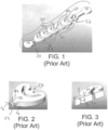
- FIG. 1 (Prior Art) shows a three-dimensional perspective view of a portion of a process fluid passage according to a prior art flow reactor
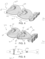
- FIG. 2 shows an individual chamber of the passage of FIG. 1
- FIG. 3 shows, in perspective view, a cross-section of the chamber of FIG. 2 .
- a flow reactor of the general type disclosed herein comprises a module having a process fluid passage 20 therein, the process fluid passage comprising an interior surface 22, the process fluid passage 20 further comprising a portion 30 thereof, which portion further comprises an input end 32 at which process fluid is to flow into the portion 30 during use and an output end 34 at which process fluid is to flow out of the portion 30 during use.
- the portion 20 also comprises a cross section 36 along the portion 30, delimited by the interior surface 22 of the passage 20 along the portion 30, the cross section 36 having a cross-sectional area and a cross-sectional shape 38, the cross-sectional area having multiple minima 40 along the passage 20 between the input end 32 and the output end 34.
- FIGS. 4 and 5 each show a three-dimensional perspective view of a portion of a process fluid passage in accordance with embodiments of the present disclosure
- FIG. 6 shows a cross-sectional view of a the passage of FIG. 5
- the reactor is characterized in that the portion 30 of the passage 20 has (1) a cross-sectional shape 38 which varies continually along the portion 30, (2) an interior surface 22 (along the portion 30) which includes either no pairs of opposing flat parallel sides 42 (as seen in FIG.
- the height of the portion 30 of the passage 20 may vary periodically with the chambers themselves, so that each successive chamber is essentially identical. Alternatively, a period of variation in the height of the portion 20 of the passage 20 may be shorter, in length along the portion 30, or longer, as in the embodiment of FIG. 5 . This results in obstacles 50 having varying height, as shown in the cross section of FIG. 6 .
- Cross sections of additional embodiments of portions 30 of passages 20 are shown in FIGS. 8-10 , with obstacles 50 of varying heights in the successive chambers 52 of FIG. 8 , or of the same height in the successive chambers 52 of FIG. 9 .
- Obstacles 50 also extend only partially across the height of the chambers 52, as shown in the embodiment of FIG. 10 . (Such obstacles effectively have only a single bypass path, albeit with a complex shape and flow pattern.) Variation in the height of the portion 30 of the passage 20 may also be asymmetrical, or the curvature of the successive chambers 52 may be asymmetrical. In the embodiment of FIG.7 and as seen in the figure, every other chamber 52 has a larger "bulge” (or a smaller radius of curvature) on the upper inside surface of the chamber (relative to the lower inside surface), while the remaining chambers 52 have a a larger "bulge” (or a smaller radius of curvature) on the lower insider surface (relative to the upper).
- a straight line 60 having a first endpoint located at a center of the entrance of the chamber 52 and a second endpoint locate at a center of the exit of the chamber is intersected by the obstacle 50.
- the obstacle 50 intersects not just the line 60 from the center point of the entrance to the center point of the exit of the chamber 52, but every line segment originating within the entrance of the chamber and ending within the exit of the chamber. In other words, desirably, there is no "line-of-sight" from the entrance to the exit of the chamber 52 even in the case that the obstacle extends only partially across the height of the chamber.
- the portions 30 of passages 20 herein include one or more bypass paths 64, as indicated, for example, in FIGS. 4 and 5 .
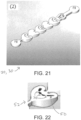
- the bypass paths 64 are paths positioned between the obstacle 50 and an inside surface of the associated chamber 52, and which lead around the obstacle 50. Such bypass paths 64 are distinguished from openings extending through an obstacle 50. Such openings 70 are seen in the embodiment of FIGS. 21-22 .
- the obstacle 50 has no openings extending through the obstacle 50.
- the one or more bypass paths 64 have a total cross-sectional area 66 greater than the total cross-sectional area 68 of the exit of the associated chamber.
- FIG. 11 shows a translucent perspective view of a portion of a process fluid passage in accordance with embodiments of the present disclosure
- FIG. 12 shows a cross-sectional view of a portion of a process fluid passage in accordance with embodiments of the present disclosure, of the type of the embodiment of FIG. 11 .
- one or more chambers 52 have both an obstacle 50 and a second obstacle 51 in the same chamber 52.
- the obstacle 50 and second obstacle 52 extend only partially across the height of the chamber 52 (as seen most clearly in FIG. 12 ), and desirably they are attached alternately to the "floor" and "ceiling" of the chamber 52.
- the obstacle or the second obstacle 52 may not, alone, intersect all lines of sight between the respective chamber's entrance and exit (or even the centerline between them), but it is desirable that they do so when considered together.
- the chambers 52 may have or almost have rotational symmetry, such that the height and width of the chambers are both considered instead as a diameter.
- FIGS. 13-18 each show a cut-away perspective view of a portion of a process fluid passage in which the portion 30 of the passage 20, as well as the successive chambers 51, have rotational symmetry. In embodiments such as these, three or more bypass paths may be used.
- the obstacles 50 comprise a flat or concave surface 72 aligned generally perpendicularly to the portion 30 of the process fluid passage 20.
- the surface 72 may preferably face in an upstream direction as shown in the embodiments of FIGS. 15, 16, and 18 , but in alternative embodiments may face in a downstream direction as in the embodiment of FIG. 17 .
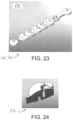
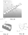
- FIGS. 19-32 show embodiments which were fabricated and performance tested in comparison to a reference embodiment (the embodiment of FIGS. 1-3 ).
- the embodiment of FIG. 25 has chambers 52 similar to those of the embodiment of FIG. 19 , except raised “ceilings” and lowered “floors” 78, relative to the embodiment of FIG. 19 Results are shown in FIGS. 33-36 .
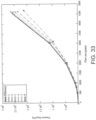
- FIGS. 33 and 34 are graphs of measured pressure drop.
- FIG. 33 results are from relatively larger scale passages
- FIG. 34 from relatively smaller scale passages.
- the numbers in the keys correspond to the numbers given for each embodiment in FIGS. 19-32 .
- all tested embodiments outperformed the reference embodiment in achieving lower pressure drop.
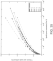
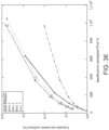
- FIGS. 35 and 36 are graphs of measured volumetric mass transfer coefficient as a function of specific power consumption, with FIG. 35 results from relatively larger scale passages and FIG. 36 results from relatively smaller scale passages. As seen in FIG. 35 , all tested embodiments other than number 2 and 5 outperformed the reference on this measure and in FIG. 36 all other than number 2. Accordingly, it is believed to be desirable to have no openings extending through the obstacles (as in embodiment number 2).
- bypass paths when there are two (or possibly more) in a chamber, separated by the obstacle by a distance of at least 2, 2.5, 3, 3.5 or even 4 times a maximum diameter of the exit of the chamber, unlike in embodiment number 5 in which a post or wedge 80 separates two bypass paths by only a short distance.
- the interior surface 22 (of the portion 30) passage 20 may include an internal screw thread structure 76 to impart an additional, helical motion to the fluid moving in the portion of the passage.
- Ranges can be expressed herein as from “about” one particular value, and/or to “about” another particular value. When such a range is expressed, embodiments include from the one particular value and/or to the other particular value. Similarly, when values are expressed as approximations, by use of the antecedent "about,” it will be understood that the particular value forms another aspect. It will be further understood that the endpoints of each of the ranges are significant both in relation to the other endpoint, and independently of the other endpoint.
Landscapes
- Chemical & Material Sciences (AREA)
- Chemical Kinetics & Catalysis (AREA)
- Organic Chemistry (AREA)
- Dispersion Chemistry (AREA)
- Physical Or Chemical Processes And Apparatus (AREA)
- Organic Low-Molecular-Weight Compounds And Preparation Thereof (AREA)
Claims (13)
- Strömungsreaktor, umfassend:ein Modul, das einen Prozessflüssigkeitsdurchgang darin aufweist, wobei der Prozessflüssigkeitsdurchgang eine innere Oberfläche umfasst, wobei der Prozessflüssigkeitsdurchgang ferner einen Abschnitt davon umfasst, wobei der Abschnitt ferner Folgendes umfasst:(1) ein Eingangsende, an dem Prozessflüssigkeit während Verwendung in den Abschnitt strömen soll, und(2) ein Ausgangsende, an dem Prozessflüssigkeit während Verwendung aus dem Abschnitt strömen soll, und(3) einen Querschnitt entlang des Abschnittes, der durch die innere Oberfläche des Durchgangs entlang des Abschnittes begrenzt ist, wobei der Querschnitt eine Querschnittsfläche und eine Querschnittsform aufweist, wobei die Querschnittsfläche mehrere Minima entlang des Durchgangs zwischen dem Eingangsende und dem Ausgangsende aufweist, wobei der Durchgang dadurch gekennzeichnet ist, dass (1) die Querschnittsform des Abschnittes entlang des Abschnittes kontinuierlich variiert, (2) die innere Oberfläche des Abschnittes entweder keine Paare gegenüberliegender flacher paralleler Seiten oder nur Paare aus gegenüberliegenden flachen parallelen Seiten beinhaltet, die sich über eine Länge von nicht mehr als dem 4-Fachen eines Abstands zwischen den gegenüberliegenden flachen parallelen Seiten entlang des Abschnittes erstrecken, und (3) der Abschnitt eine Vielzahl von Hindernissen enthält, die entlang des Abschnittes zwischen dem Eingangsende und dem Ausgangsende positioniert ist;wobei der Abschnitt ferner aufeinanderfolgende Kammern jeweils mit einem düsenartigen Eintritt und einem sich verengenden Austritt umfasst;wobei sich zumindest eines aus der Vielzahl von Hindernissen innerhalb einer ersten Kammer befindet und eine gerade Linie schneidet, die einen ersten Endpunkt, der sich in einer Mitte des Eintritts der ersten Kammer befindet, und einen zweiten Endpunkt, der sich in der Mitte des Austritts der ersten Kammer befindet, aufweist; wobei der Strömungsreaktor ferner zwei oder mehr Hindernisse in einer einzelnen Kammer umfasst; und wobei sich die Hindernisse nur teilweise über die Höhe der Kammer erstrecken.
- Strömungsreaktor nach Anspruch 1, wobei eine Kammer der aufeinanderfolgenden Kammern mit einer nächstfolgenden Kammer der aufeinanderfolgenden Kammern verschachtelt ist, sodass der sich verengende Austritt der einen Kammer den düsenartigen Eintritt der nächsten benachbarten aufeinanderfolgenden Kammer bildet.
- Strömungsreaktor nach Anspruch 1 oder Anspruch 2, wobei das zumindest eine aus der Vielzahl von Hindernissen jede gerade Linie schneidet, die einen ersten Endpunkt innerhalb des Eintritts der ersten Kammer und einen zweiten Endpunkt innerhalb des Austritts der ersten Kammer aufweist.
- Strömungsreaktor nach einem der Ansprüche 1 bis 3, der einen oder mehrere Umgehungspfade aufweist, die zwischen dem zumindest einen Hindernis und einer Innenoberfläche der ersten Kammer um das zumindest eine Hindernis aus der Vielzahl von Hindernissen positioniert sind.
- Strömungsreaktor nach Anspruch 4, wobei der eine oder die mehreren Umgehungspfade eine Gesamtquerschnittsfläche aufweisen, die größer als die Gesamtquerschnittsfläche des Austritts der ersten Kammer ist.
- Strömungsreaktor nach Anspruch 4, wobei das zumindest eine Hindernis eine oder mehrere Öffnungen aufweist, die sich durch das zumindest eine Hindernis erstrecken.
- Strömungsreaktor nach Anspruch 4, wobei das zumindest eine Hindernis keine Öffnungen aufweist, die sich durch das zumindest eine Hindernis erstrecken.
- Strömungsreaktor nach einem der Ansprüche 1-7, wobei die Vielzahl von Hindernissen zumindest drei oder mehr Hindernisse umfasst.
- Strömungsreaktor nach einem der Ansprüche 1-8, wobei das zumindest eine aus der Vielzahl von Hindernissen eine flache oder konkave Oberfläche umfasst, die im Allgemeinen senkrecht zu dem Prozessflüssigkeitsdurchgang ausgerichtet ist.
- Strömungsreaktor nach Anspruch 9, wobei die flache oder konkave Oberfläche in eine stromabwärtige Richtung weist.
- Strömungsreaktor nach Anspruch 9, wobei die flache oder konkave Oberfläche in eine stromaufwärtige Richtung weist.
- Strömungsreaktor nach einem der Ansprüche 1-8, wobei das zumindest eine aus der Vielzahl von Hindernissen ein sich verjüngendes längliches Ende umfasst, das in eine stromabwärtige Richtung zeigt.
- Strömungsreaktor nach einem der Ansprüche 1-8, wobei das zumindest eine Hindernis aus der Vielzahl von Hindernissen ein sich verjüngendes längliches Ende umfasst, das in eine stromaufwärtige Richtung zeigt.
Priority Applications (1)
| Application Number | Priority Date | Filing Date | Title |
|---|---|---|---|
| EP23197105.2A EP4268947A3 (de) | 2017-07-31 | 2018-07-31 | Verbesserter reaktor mit verstärktem durchfluss |
Applications Claiming Priority (2)
| Application Number | Priority Date | Filing Date | Title |
|---|---|---|---|
| US201762539541P | 2017-07-31 | 2017-07-31 | |
| PCT/US2018/044572 WO2019028002A1 (en) | 2017-07-31 | 2018-07-31 | PERFECTED CONTINUOUS REACTOR |
Related Child Applications (2)
| Application Number | Title | Priority Date | Filing Date |
|---|---|---|---|
| EP23197105.2A Division EP4268947A3 (de) | 2017-07-31 | 2018-07-31 | Verbesserter reaktor mit verstärktem durchfluss |
| EP23197105.2A Division-Into EP4268947A3 (de) | 2017-07-31 | 2018-07-31 | Verbesserter reaktor mit verstärktem durchfluss |
Publications (2)
| Publication Number | Publication Date |
|---|---|
| EP3661640A1 EP3661640A1 (de) | 2020-06-10 |
| EP3661640B1 true EP3661640B1 (de) | 2023-10-25 |
Family
ID=63449644
Family Applications (2)
| Application Number | Title | Priority Date | Filing Date |
|---|---|---|---|
| EP18762656.9A Active EP3661640B1 (de) | 2017-07-31 | 2018-07-31 | Verbesserter prozessintensivierter strömungsreaktor |
| EP23197105.2A Withdrawn EP4268947A3 (de) | 2017-07-31 | 2018-07-31 | Verbesserter reaktor mit verstärktem durchfluss |
Family Applications After (1)
| Application Number | Title | Priority Date | Filing Date |
|---|---|---|---|
| EP23197105.2A Withdrawn EP4268947A3 (de) | 2017-07-31 | 2018-07-31 | Verbesserter reaktor mit verstärktem durchfluss |
Country Status (7)
| Country | Link |
|---|---|
| US (2) | US11192084B2 (de) |
| EP (2) | EP3661640B1 (de) |
| JP (2) | JP7212671B2 (de) |
| KR (2) | KR102866720B1 (de) |
| CN (4) | CN115178206B (de) |
| TW (2) | TWI826386B (de) |
| WO (1) | WO2019028002A1 (de) |
Families Citing this family (14)
| Publication number | Priority date | Publication date | Assignee | Title |
|---|---|---|---|---|
| EP3661640B1 (de) * | 2017-07-31 | 2023-10-25 | Corning Incorporated | Verbesserter prozessintensivierter strömungsreaktor |
| EP3939967A1 (de) | 2020-07-15 | 2022-01-19 | KRKA, d.d., Novo mesto | Kontinuierliches verfahren zur herstellung von (s)-methyl-n-((2'-cyano-[1,1'-biphenyl]-4-yl)methyl)-n-pentanoylvalinat n einem strömungsreaktor |
| CN112403412A (zh) * | 2020-09-29 | 2021-02-26 | 合肥通用机械研究院有限公司 | 一种微反应器和用于微反应器的强化混合结构 |
| DE102021115994B3 (de) * | 2021-06-21 | 2022-12-08 | Institut für Bioprozess- und Analysenmesstechnik e.V. | Vorrichtung und Verfahren für das Mischen von zwei Flüssigkeiten oder Pasten |
| CN115554943B (zh) * | 2021-07-02 | 2025-04-29 | 中国石油化工股份有限公司 | 微反应器 |
| CN116408159A (zh) * | 2021-12-31 | 2023-07-11 | Tcl科技集团股份有限公司 | 一种微反应通道、微流反应器和量子点的制备方法 |
| KR102881310B1 (ko) | 2022-12-12 | 2025-11-05 | 주식회사 지앤아이솔루션 | 연속흐름반응기를 이용한 유기물 정제 방법 및 장치 |
| KR20240096259A (ko) | 2022-12-19 | 2024-06-26 | 주식회사 지앤아이솔루션 | 연속흐름반응기를 이용한 양자점 제조 방법 |
| KR20240096257A (ko) | 2022-12-19 | 2024-06-26 | 주식회사 지앤아이솔루션 | 연속흐름반응기를 이용한 양자점 제조 장치 |
| KR20240148133A (ko) * | 2023-04-03 | 2024-10-11 | 주식회사 지앤아이솔루션 | 균질기 |
| KR102794177B1 (ko) * | 2023-08-31 | 2025-04-15 | 주식회사 이엔에프테크놀로지 | 음이온 중합 방법에 의한 기능성 중합체의 제조방법 |
| WO2025048575A1 (ko) * | 2023-08-31 | 2025-03-06 | 주식회사 이엔에프테크놀로지 | 음이온 중합 방법에 의한 기능성 중합체의 제조방법 |
| WO2025048586A1 (ko) * | 2023-08-31 | 2025-03-06 | 주식회사 이엔에프테크놀로지 | 음이온 중합 방법에 의한 기능성 중합체의 제조방법 |
| WO2025048581A1 (ko) * | 2023-08-31 | 2025-03-06 | 주식회사 이엔에프테크놀로지 | 음이온 중합 방법에 의한 기능성 중합체의 제조방법 |
Family Cites Families (88)
| Publication number | Priority date | Publication date | Assignee | Title |
|---|---|---|---|---|
| JPS5211221B1 (de) * | 1969-03-17 | 1977-03-29 | ||
| US3927868A (en) * | 1974-05-28 | 1975-12-23 | Thomas B Moore | Static-type mixer, and receptacle and method of packaging utilizing same |
| US4087862A (en) * | 1975-12-11 | 1978-05-02 | Exxon Research & Engineering Co. | Bladeless mixer and system |
| JPS52151676A (en) * | 1976-06-11 | 1977-12-16 | Fuji Photo Film Co Ltd | Method and equipment for dispersing |
| JP2513475B2 (ja) * | 1986-10-21 | 1996-07-03 | ノードソン株式会社 | 液体の混合吐出又は噴出方法とその装置 |
| DE10019759C2 (de) * | 2000-04-20 | 2003-04-30 | Tracto Technik | Statisches Mischsystem |
| DE10032059A1 (de) | 2000-07-05 | 2002-01-17 | Mir Chem Gmbh | Vorrichtung zum Ausführen einer katalytischen Rohrreaktion |
| SE520749C2 (sv) | 2001-12-21 | 2003-08-19 | Tetra Laval Holdings & Finance | Statisk blandare för kontinuerlig omblandning av ett eller flera flöden |
| US8206666B2 (en) * | 2002-05-21 | 2012-06-26 | Battelle Memorial Institute | Reactors having varying cross-section, methods of making same, and methods of conducting reactions with varying local contact time |
| JP2004024992A (ja) | 2002-06-24 | 2004-01-29 | Atec Japan:Kk | マイクロリアクター及びそれを用いた化学反応方法 |
| JP3888632B2 (ja) * | 2003-03-26 | 2007-03-07 | 靖浩 堀池 | マイクロミキサ、試料分析キット及びその製造方法 |
| US20040228211A1 (en) | 2003-05-13 | 2004-11-18 | Koripella Chowdary R. | Internal micromixer |
| DE102004036951A1 (de) | 2003-08-01 | 2005-05-25 | Behr Gmbh & Co. Kg | Wärmeübertrager sowie Verfahren zu dessen Herstellung |
| PT103072B (pt) | 2004-02-13 | 2009-12-02 | Faculdade De Engenharia Da Uni | Misturador em rede e respectivo processo de mistura |
| EP1604733A1 (de) | 2004-06-11 | 2005-12-14 | Corning Incorporated | Mikrostrukturentwurf zur Optimisierung der Mischung und des Druckabfalls |
| JP4444018B2 (ja) * | 2004-06-22 | 2010-03-31 | シャープ株式会社 | マイクロリアクタ |
| JP4454431B2 (ja) * | 2004-08-13 | 2010-04-21 | アルプス電気株式会社 | プレート |
| GB0420971D0 (en) | 2004-09-21 | 2004-10-20 | Imp College Innovations Ltd | Piping |
| JP4892183B2 (ja) | 2004-10-08 | 2012-03-07 | 株式会社フジキン | 流体混合装置 |
| JP2006122736A (ja) | 2004-10-26 | 2006-05-18 | Dainippon Screen Mfg Co Ltd | 流路構造体およびその製造方法 |
| US7510688B2 (en) | 2005-09-26 | 2009-03-31 | Lg Chem, Ltd. | Stack type reactor |
| JP4598646B2 (ja) | 2005-10-18 | 2010-12-15 | 学校法人早稲田大学 | マイクロ反応装置 |
| JP2007136322A (ja) | 2005-11-17 | 2007-06-07 | Konica Minolta Medical & Graphic Inc | 反応物質同士の拡散および反応を効率化したマイクロリアクタ、およびそれを用いた反応方法 |
| JP2007190505A (ja) * | 2006-01-20 | 2007-08-02 | Kao Corp | マイクロ流体デバイス |
| US7794136B2 (en) | 2006-05-09 | 2010-09-14 | National Tsing Hua University | Twin-vortex micromixer for enforced mass exchange |
| JP4677969B2 (ja) | 2006-10-06 | 2011-04-27 | 株式会社日立プラントテクノロジー | マイクロリアクタ |
| TW200819387A (en) | 2006-10-19 | 2008-05-01 | Univ Yuan Ze | Micro-reacting device having a micro-channel flow-guiding block |
| JP2008114162A (ja) | 2006-11-06 | 2008-05-22 | Dainippon Printing Co Ltd | マイクロリアクターおよびその製造方法 |
| EP2017000B1 (de) * | 2007-07-11 | 2012-09-05 | Corning Incorporated | Mikrofluidische Geräte für verstärkte Verfahren |
| JP2009082803A (ja) | 2007-09-28 | 2009-04-23 | Dainippon Printing Co Ltd | マイクロリアクターおよびその製造方法 |
| JP2009090248A (ja) | 2007-10-11 | 2009-04-30 | Fuji Xerox Co Ltd | マイクロ流路構造体、マイクロ流路構造体の製造方法及びマイクロリアクター |
| KR100898065B1 (ko) | 2007-10-19 | 2009-05-15 | 송상섭 | 마이크로 리액터 |
| JP4877211B2 (ja) | 2007-11-28 | 2012-02-15 | 大日本印刷株式会社 | マイクロリアクターおよびその製造方法 |
| KR100934267B1 (ko) | 2008-02-04 | 2009-12-28 | 한국과학기술원 | 다공성 나선 구조를 가지는 믹서 및 필터와, 이를 구비한 마이크로 채널 소자 |
| TW200940162A (en) | 2008-03-18 | 2009-10-01 | Jing-Tang Yang | A micromixer and microreactor with split-and-recombination and chaotic mechanisms |
| JP5504526B2 (ja) | 2008-03-25 | 2014-05-28 | 学校法人加計学園 | マイクロリアクターを用いてスラグ流を形成する方法 |
| TW200946914A (en) | 2008-05-02 | 2009-11-16 | Univ Nat Cheng Kung | Micro mixer initiative control mechanism for a structure that has both a blunt body and a concave-convex surface |
| US8277112B2 (en) | 2008-05-27 | 2012-10-02 | The Research Foundation Of State University Of New York | Devices and fluid flow methods for improving mixing |
| WO2010009239A2 (en) | 2008-07-18 | 2010-01-21 | 3M Innovative Properties Company | Tortuous path static mixers and fluid systems including the same |
| KR101003654B1 (ko) | 2008-08-27 | 2010-12-23 | 삼성전기주식회사 | 반도체 패키지용 트랜스포머 |
| US8430558B1 (en) | 2008-09-05 | 2013-04-30 | University Of Central Florida Research Foundation, Inc. | Microfluidic mixer having channel width variation for enhanced fluid mixing |
| EP2172260A1 (de) | 2008-09-29 | 2010-04-07 | Corning Incorporated | Mehrflussweg-Mikroflüssigkeitsvorrichtungen |
| EP2184103A1 (de) | 2008-11-11 | 2010-05-12 | Onea Engineering Austria GmbH | Modularer Reaktor |
| SE534745C2 (sv) | 2009-04-15 | 2011-12-06 | Alfa Laval Corp Ab | Flödesmodul |
| DE202009017416U1 (de) | 2009-05-12 | 2010-04-15 | Lonza Ag | Reaktor und Satz aus Reaktoren |
| DE202010000262U1 (de) | 2009-05-12 | 2010-05-20 | Lonza Ag | Strömungsreaktor mit Mikrokanalsystem |
| JP5439479B2 (ja) | 2009-05-14 | 2014-03-12 | 株式会社日立製作所 | マイクロリアクタシステム |
| RU2009120627A (ru) | 2009-05-29 | 2010-12-10 | Корнинг Инкорпорейтед (US) | Микрожидкостные устройства с регулированием потока |
| JP2011020044A (ja) | 2009-07-15 | 2011-02-03 | Dainippon Printing Co Ltd | マイクロリアクターおよびその製造方法 |
| JP2011036773A (ja) | 2009-08-10 | 2011-02-24 | Hitachi Ltd | 反応装置及び反応プラント |
| TW201107092A (en) * | 2009-08-20 | 2011-03-01 | Cheng-Wei Su | Multiple-bump hand tool structure |
| GB0919702D0 (en) | 2009-11-11 | 2009-12-30 | Ashe Morris Ltd | Improved agitated cell reactor |
| KR101176175B1 (ko) | 2010-07-30 | 2013-05-09 | 광주과학기술원 | 마이크로 믹서 및 이의 제조 방법 |
| EP2452743A1 (de) | 2010-11-12 | 2012-05-16 | Lonza AG | Reaktor zur Durchführung von chemischen Reaktionen |
| TWI429484B (zh) | 2010-12-31 | 2014-03-11 | Resi Corp | 管型連續式反應器以及應用於該反應器之波浪型反應器管 |
| CN102188943B (zh) | 2011-05-16 | 2013-08-28 | 利穗科技(苏州)有限公司 | 一种撞击流多级微反应器 |
| CN102188944B (zh) | 2011-05-16 | 2013-08-28 | 利穗科技(苏州)有限公司 | 一种混沌型多级涡流微反应器 |
| CN202096947U (zh) | 2011-05-16 | 2012-01-04 | 利穗科技(苏州)有限公司 | 一种撞击流多级微反应器 |
| CN202169168U (zh) | 2011-05-16 | 2012-03-21 | 利穗科技(苏州)有限公司 | 一种混沌型多级涡流微反应器 |
| US20140104975A1 (en) | 2011-05-31 | 2014-04-17 | Mikhail Sergeevich Chivilikhin | Twist flow microfluidic mixer and module |
| TW201302299A (zh) | 2011-07-15 | 2013-01-16 | Univ Nat Cheng Kung | 微型混合元件 |
| US20130021868A1 (en) | 2011-07-22 | 2013-01-24 | Doolin Michael B | Static Fluid Mixer and Method |
| CN202191898U (zh) | 2011-08-01 | 2012-04-18 | 利穗科技(苏州)有限公司 | 一种毛虫型微反应器 |
| CN202191899U (zh) | 2011-08-01 | 2012-04-18 | 利穗科技(苏州)有限公司 | 一种撞击型微反应器 |
| CN102240535A (zh) | 2011-08-01 | 2011-11-16 | 利穗科技(苏州)有限公司 | 一种毛虫型微反应器 |
| CN202191902U (zh) | 2011-08-01 | 2012-04-18 | 利穗科技(苏州)有限公司 | 一种混沌型微反应器 |
| CN102350286B (zh) | 2011-08-01 | 2013-11-27 | 利穗科技(苏州)有限公司 | 一种撞击型微反应器 |
| CN102247787A (zh) | 2011-08-01 | 2011-11-23 | 利穗科技(苏州)有限公司 | 一种混沌型微反应器 |
| WO2013054180A1 (en) | 2011-10-14 | 2013-04-18 | Council Of Scientific & Industrial Research | Continuous modular reactor |
| CN202527089U (zh) | 2012-02-24 | 2012-11-14 | 张端 | 新型回流式微混合器 |
| CN102553482A (zh) | 2012-02-24 | 2012-07-11 | 张端 | 新型回流式微混合器 |
| WO2014009286A1 (en) * | 2012-07-07 | 2014-01-16 | Creoptix Gmbh | Flow conduit system for a biochemical sensor |
| CN203525623U (zh) | 2012-12-21 | 2014-04-09 | 江苏大学 | 一种压电微混合器 |
| KR101432729B1 (ko) | 2012-12-24 | 2014-08-21 | 인하대학교 산학협력단 | 원반형의 혼합부와 교차되는 혼합채널을 가진 미세혼합기 |
| JP2014198324A (ja) * | 2013-03-29 | 2014-10-23 | ソニー株式会社 | マイクロ流路及びマイクロ流体デバイス |
| CN103285798B (zh) | 2013-06-27 | 2015-04-22 | 利穗科技(苏州)有限公司 | 一种多层多级微反应器 |
| CN103638853B (zh) | 2013-11-11 | 2015-10-28 | 江苏大学 | 一种s型被动式微混合器 |
| CN103877905B (zh) | 2013-11-11 | 2016-01-20 | 江苏大学 | 一种被动式微混合器 |
| KR20150105856A (ko) | 2014-03-10 | 2015-09-18 | 연세대학교 산학협력단 | 테일러 괴틀러 와류를 이용한 마이크로 믹서 및 그 제작방법 |
| CN104138728B (zh) | 2014-04-17 | 2016-01-27 | 西北工业大学 | 一种桥式结构的分割重组被动式微混合器 |
| CN104307413B (zh) | 2014-09-11 | 2016-05-11 | 浙江工业大学 | T型微混合器 |
| CN204193922U (zh) | 2014-10-27 | 2015-03-11 | 大连韦德生化科技有限公司 | 一种具有水滴状微结构的微反应器装置 |
| CN204338128U (zh) | 2014-12-18 | 2015-05-20 | 郑州大学 | 微型气液反应器及微型气液反应装置 |
| CN104525031B (zh) | 2014-12-21 | 2016-07-06 | 北京工业大学 | 一种被动式多内肋结构环形微混合器 |
| CN204429262U (zh) | 2015-01-26 | 2015-07-01 | 深圳市一正科技有限公司 | 微反应器 |
| US9587545B2 (en) * | 2015-01-26 | 2017-03-07 | Caterpillar Inc. | Flow agitator |
| CN109863501B (zh) * | 2016-07-22 | 2022-12-27 | 康奈尔大学 | 针对患者定制的冠状动脉旁路移植物的快速成型和体外建模 |
| EP3661640B1 (de) * | 2017-07-31 | 2023-10-25 | Corning Incorporated | Verbesserter prozessintensivierter strömungsreaktor |
-
2018
- 2018-07-31 EP EP18762656.9A patent/EP3661640B1/de active Active
- 2018-07-31 CN CN202210865164.5A patent/CN115178206B/zh not_active Expired - Fee Related
- 2018-07-31 CN CN202210863734.7A patent/CN115155480B/zh not_active Expired - Fee Related
- 2018-07-31 EP EP23197105.2A patent/EP4268947A3/de not_active Withdrawn
- 2018-07-31 WO PCT/US2018/044572 patent/WO2019028002A1/en not_active Ceased
- 2018-07-31 TW TW107126473A patent/TWI826386B/zh not_active IP Right Cessation
- 2018-07-31 TW TW112144214A patent/TW202410963A/zh unknown
- 2018-07-31 US US16/635,069 patent/US11192084B2/en active Active
- 2018-07-31 KR KR1020237034161A patent/KR102866720B1/ko active Active
- 2018-07-31 CN CN201880050026.3A patent/CN111225739B/zh active Active
- 2018-07-31 CN CN202210868551.4A patent/CN115193359B/zh not_active Expired - Fee Related
- 2018-07-31 JP JP2020505369A patent/JP7212671B2/ja active Active
- 2018-07-31 KR KR1020207005861A patent/KR102588588B1/ko active Active
-
2021
- 2021-11-02 US US17/517,104 patent/US11679368B2/en active Active
-
2023
- 2023-01-13 JP JP2023003761A patent/JP2023040249A/ja active Pending
Also Published As
| Publication number | Publication date |
|---|---|
| CN115178206B (zh) | 2023-09-29 |
| US20200246772A1 (en) | 2020-08-06 |
| CN115178206A (zh) | 2022-10-14 |
| US11679368B2 (en) | 2023-06-20 |
| KR20230148262A (ko) | 2023-10-24 |
| CN115155480B (zh) | 2023-09-29 |
| KR102866720B1 (ko) | 2025-10-02 |
| EP3661640A1 (de) | 2020-06-10 |
| JP7212671B2 (ja) | 2023-01-25 |
| TWI826386B (zh) | 2023-12-21 |
| CN115193359B (zh) | 2023-09-29 |
| JP2023040249A (ja) | 2023-03-22 |
| JP2020529309A (ja) | 2020-10-08 |
| KR102588588B1 (ko) | 2023-10-12 |
| CN115193359A (zh) | 2022-10-18 |
| US20220055009A1 (en) | 2022-02-24 |
| EP4268947A3 (de) | 2024-01-17 |
| CN115155480A (zh) | 2022-10-11 |
| TW202410963A (zh) | 2024-03-16 |
| TW201929955A (zh) | 2019-08-01 |
| CN111225739B (zh) | 2022-08-09 |
| US11192084B2 (en) | 2021-12-07 |
| KR20200037319A (ko) | 2020-04-08 |
| EP4268947A2 (de) | 2023-11-01 |
| WO2019028002A1 (en) | 2019-02-07 |
| CN111225739A (zh) | 2020-06-02 |
Similar Documents
| Publication | Publication Date | Title |
|---|---|---|
| EP3661640B1 (de) | Verbesserter prozessintensivierter strömungsreaktor | |
| EP1412044B1 (de) | System zum strippen und rektifizieren eines fluidgemisches | |
| CN110090607B (zh) | 一种微反应器 | |
| CN210131619U (zh) | 一种微通道反应结构及微通道反应器 | |
| CN211886766U (zh) | 一种旋流式微反应通道、基板、反应器及系统 | |
| CA2396664A1 (en) | Tube reactor based on a laminate | |
| CN106140050A (zh) | 反应器单元及双面型微反应器系统 | |
| KR101300485B1 (ko) | 수동형 미세 혼합기 | |
| CN111957279B (zh) | 微通道结构、具有其的微通道反应组件和微通道反应器 | |
| CN116550245A (zh) | 含立体阶梯通道的双层复合微反应通道板、微通道反应器 | |
| CN114887564B (zh) | 一种微通道反应器 | |
| CN113893796B (zh) | 一种链式微反应器 | |
| CN106215789A (zh) | 一种基于射流原理的回流被动式微混合器 | |
| CN108548437B (zh) | 基于仿生的鱼刺型微小交错肺泡换热器芯体及换热器 | |
| CN217910363U (zh) | 一种连续流微通道反应器 | |
| CN207300031U (zh) | 一种曲面板及使用该曲面板的流体交互装置 | |
| RU2050914C1 (ru) | Вихревой тепломассообменный аппарат | |
| CN116832733B (zh) | 一种微反应器及其微通道 | |
| CN107543445A (zh) | 曲面板及使用该曲面板的流体交互装置 | |
| CN119687705A (zh) | 一种薄壁微通道换热器 | |
| Le The et al. | A novel design of passive split and recombination micromixer with trapezoidal zigzag channels | |
| CN118751175A (zh) | 一种具有多层插片微通道的管壳式反应器 | |
| PATEL et al. | HEAT EXCHANGE PROCESS INTENSIFICATION: REENGINEERING THE THINGS | |
| WO2010141366A2 (en) | Pressure resistant honeycomb reactor |
Legal Events
| Date | Code | Title | Description |
|---|---|---|---|
| STAA | Information on the status of an ep patent application or granted ep patent |
Free format text: STATUS: UNKNOWN |
|
| STAA | Information on the status of an ep patent application or granted ep patent |
Free format text: STATUS: THE INTERNATIONAL PUBLICATION HAS BEEN MADE |
|
| PUAI | Public reference made under article 153(3) epc to a published international application that has entered the european phase |
Free format text: ORIGINAL CODE: 0009012 |
|
| STAA | Information on the status of an ep patent application or granted ep patent |
Free format text: STATUS: REQUEST FOR EXAMINATION WAS MADE |
|
| 17P | Request for examination filed |
Effective date: 20200220 |
|
| AK | Designated contracting states |
Kind code of ref document: A1 Designated state(s): AL AT BE BG CH CY CZ DE DK EE ES FI FR GB GR HR HU IE IS IT LI LT LU LV MC MK MT NL NO PL PT RO RS SE SI SK SM TR |
|
| AX | Request for extension of the european patent |
Extension state: BA ME |
|
| DAV | Request for validation of the european patent (deleted) | ||
| DAX | Request for extension of the european patent (deleted) | ||
| STAA | Information on the status of an ep patent application or granted ep patent |
Free format text: STATUS: EXAMINATION IS IN PROGRESS |
|
| 17Q | First examination report despatched |
Effective date: 20210125 |
|
| RIC1 | Information provided on ipc code assigned before grant |
Ipc: B01F 33/00 20220101ALI20230404BHEP Ipc: B01F 25/00 20220101ALI20230404BHEP Ipc: B01J 19/00 20060101AFI20230404BHEP |
|
| GRAP | Despatch of communication of intention to grant a patent |
Free format text: ORIGINAL CODE: EPIDOSNIGR1 |
|
| STAA | Information on the status of an ep patent application or granted ep patent |
Free format text: STATUS: GRANT OF PATENT IS INTENDED |
|
| INTG | Intention to grant announced |
Effective date: 20230515 |
|
| GRAS | Grant fee paid |
Free format text: ORIGINAL CODE: EPIDOSNIGR3 |
|
| GRAA | (expected) grant |
Free format text: ORIGINAL CODE: 0009210 |
|
| STAA | Information on the status of an ep patent application or granted ep patent |
Free format text: STATUS: THE PATENT HAS BEEN GRANTED |
|
| P01 | Opt-out of the competence of the unified patent court (upc) registered |
Effective date: 20230911 |
|
| AK | Designated contracting states |
Kind code of ref document: B1 Designated state(s): AL AT BE BG CH CY CZ DE DK EE ES FI FR GB GR HR HU IE IS IT LI LT LU LV MC MK MT NL NO PL PT RO RS SE SI SK SM TR |
|
| REG | Reference to a national code |
Ref country code: GB Ref legal event code: FG4D |
|
| REG | Reference to a national code |
Ref country code: CH Ref legal event code: EP |
|
| REG | Reference to a national code |
Ref country code: DE Ref legal event code: R096 Ref document number: 602018059998 Country of ref document: DE |
|
| REG | Reference to a national code |
Ref country code: IE Ref legal event code: FG4D |
|
| REG | Reference to a national code |
Ref country code: NL Ref legal event code: FP |
|
| REG | Reference to a national code |
Ref country code: LT Ref legal event code: MG9D |
|
| REG | Reference to a national code |
Ref country code: AT Ref legal event code: MK05 Ref document number: 1624131 Country of ref document: AT Kind code of ref document: T Effective date: 20231025 |
|
| PG25 | Lapsed in a contracting state [announced via postgrant information from national office to epo] |
Ref country code: GR Free format text: LAPSE BECAUSE OF FAILURE TO SUBMIT A TRANSLATION OF THE DESCRIPTION OR TO PAY THE FEE WITHIN THE PRESCRIBED TIME-LIMIT Effective date: 20240126 |
|
| PG25 | Lapsed in a contracting state [announced via postgrant information from national office to epo] |
Ref country code: IS Free format text: LAPSE BECAUSE OF FAILURE TO SUBMIT A TRANSLATION OF THE DESCRIPTION OR TO PAY THE FEE WITHIN THE PRESCRIBED TIME-LIMIT Effective date: 20240225 |
|
| PG25 | Lapsed in a contracting state [announced via postgrant information from national office to epo] |
Ref country code: LT Free format text: LAPSE BECAUSE OF FAILURE TO SUBMIT A TRANSLATION OF THE DESCRIPTION OR TO PAY THE FEE WITHIN THE PRESCRIBED TIME-LIMIT Effective date: 20231025 |
|
| PG25 | Lapsed in a contracting state [announced via postgrant information from national office to epo] |
Ref country code: AT Free format text: LAPSE BECAUSE OF FAILURE TO SUBMIT A TRANSLATION OF THE DESCRIPTION OR TO PAY THE FEE WITHIN THE PRESCRIBED TIME-LIMIT Effective date: 20231025 |
|
| PG25 | Lapsed in a contracting state [announced via postgrant information from national office to epo] |
Ref country code: ES Free format text: LAPSE BECAUSE OF FAILURE TO SUBMIT A TRANSLATION OF THE DESCRIPTION OR TO PAY THE FEE WITHIN THE PRESCRIBED TIME-LIMIT Effective date: 20231025 |
|
| PG25 | Lapsed in a contracting state [announced via postgrant information from national office to epo] |
Ref country code: LT Free format text: LAPSE BECAUSE OF FAILURE TO SUBMIT A TRANSLATION OF THE DESCRIPTION OR TO PAY THE FEE WITHIN THE PRESCRIBED TIME-LIMIT Effective date: 20231025 Ref country code: IS Free format text: LAPSE BECAUSE OF FAILURE TO SUBMIT A TRANSLATION OF THE DESCRIPTION OR TO PAY THE FEE WITHIN THE PRESCRIBED TIME-LIMIT Effective date: 20240225 Ref country code: GR Free format text: LAPSE BECAUSE OF FAILURE TO SUBMIT A TRANSLATION OF THE DESCRIPTION OR TO PAY THE FEE WITHIN THE PRESCRIBED TIME-LIMIT Effective date: 20240126 Ref country code: ES Free format text: LAPSE BECAUSE OF FAILURE TO SUBMIT A TRANSLATION OF THE DESCRIPTION OR TO PAY THE FEE WITHIN THE PRESCRIBED TIME-LIMIT Effective date: 20231025 Ref country code: BG Free format text: LAPSE BECAUSE OF FAILURE TO SUBMIT A TRANSLATION OF THE DESCRIPTION OR TO PAY THE FEE WITHIN THE PRESCRIBED TIME-LIMIT Effective date: 20240125 Ref country code: AT Free format text: LAPSE BECAUSE OF FAILURE TO SUBMIT A TRANSLATION OF THE DESCRIPTION OR TO PAY THE FEE WITHIN THE PRESCRIBED TIME-LIMIT Effective date: 20231025 Ref country code: PT Free format text: LAPSE BECAUSE OF FAILURE TO SUBMIT A TRANSLATION OF THE DESCRIPTION OR TO PAY THE FEE WITHIN THE PRESCRIBED TIME-LIMIT Effective date: 20240226 |
|
| PG25 | Lapsed in a contracting state [announced via postgrant information from national office to epo] |
Ref country code: SE Free format text: LAPSE BECAUSE OF FAILURE TO SUBMIT A TRANSLATION OF THE DESCRIPTION OR TO PAY THE FEE WITHIN THE PRESCRIBED TIME-LIMIT Effective date: 20231025 Ref country code: RS Free format text: LAPSE BECAUSE OF FAILURE TO SUBMIT A TRANSLATION OF THE DESCRIPTION OR TO PAY THE FEE WITHIN THE PRESCRIBED TIME-LIMIT Effective date: 20231025 Ref country code: PL Free format text: LAPSE BECAUSE OF FAILURE TO SUBMIT A TRANSLATION OF THE DESCRIPTION OR TO PAY THE FEE WITHIN THE PRESCRIBED TIME-LIMIT Effective date: 20231025 Ref country code: NO Free format text: LAPSE BECAUSE OF FAILURE TO SUBMIT A TRANSLATION OF THE DESCRIPTION OR TO PAY THE FEE WITHIN THE PRESCRIBED TIME-LIMIT Effective date: 20240125 Ref country code: LV Free format text: LAPSE BECAUSE OF FAILURE TO SUBMIT A TRANSLATION OF THE DESCRIPTION OR TO PAY THE FEE WITHIN THE PRESCRIBED TIME-LIMIT Effective date: 20231025 Ref country code: HR Free format text: LAPSE BECAUSE OF FAILURE TO SUBMIT A TRANSLATION OF THE DESCRIPTION OR TO PAY THE FEE WITHIN THE PRESCRIBED TIME-LIMIT Effective date: 20231025 |
|
| PG25 | Lapsed in a contracting state [announced via postgrant information from national office to epo] |
Ref country code: DK Free format text: LAPSE BECAUSE OF FAILURE TO SUBMIT A TRANSLATION OF THE DESCRIPTION OR TO PAY THE FEE WITHIN THE PRESCRIBED TIME-LIMIT Effective date: 20231025 |
|
| PGFP | Annual fee paid to national office [announced via postgrant information from national office to epo] |
Ref country code: NL Payment date: 20240617 Year of fee payment: 7 |
|
| PG25 | Lapsed in a contracting state [announced via postgrant information from national office to epo] |
Ref country code: CZ Free format text: LAPSE BECAUSE OF FAILURE TO SUBMIT A TRANSLATION OF THE DESCRIPTION OR TO PAY THE FEE WITHIN THE PRESCRIBED TIME-LIMIT Effective date: 20231025 |
|
| REG | Reference to a national code |
Ref country code: DE Ref legal event code: R097 Ref document number: 602018059998 Country of ref document: DE |
|
| PG25 | Lapsed in a contracting state [announced via postgrant information from national office to epo] |
Ref country code: SK Free format text: LAPSE BECAUSE OF FAILURE TO SUBMIT A TRANSLATION OF THE DESCRIPTION OR TO PAY THE FEE WITHIN THE PRESCRIBED TIME-LIMIT Effective date: 20231025 |
|
| PG25 | Lapsed in a contracting state [announced via postgrant information from national office to epo] |
Ref country code: SM Free format text: LAPSE BECAUSE OF FAILURE TO SUBMIT A TRANSLATION OF THE DESCRIPTION OR TO PAY THE FEE WITHIN THE PRESCRIBED TIME-LIMIT Effective date: 20231025 Ref country code: SK Free format text: LAPSE BECAUSE OF FAILURE TO SUBMIT A TRANSLATION OF THE DESCRIPTION OR TO PAY THE FEE WITHIN THE PRESCRIBED TIME-LIMIT Effective date: 20231025 Ref country code: RO Free format text: LAPSE BECAUSE OF FAILURE TO SUBMIT A TRANSLATION OF THE DESCRIPTION OR TO PAY THE FEE WITHIN THE PRESCRIBED TIME-LIMIT Effective date: 20231025 Ref country code: IT Free format text: LAPSE BECAUSE OF FAILURE TO SUBMIT A TRANSLATION OF THE DESCRIPTION OR TO PAY THE FEE WITHIN THE PRESCRIBED TIME-LIMIT Effective date: 20231025 Ref country code: EE Free format text: LAPSE BECAUSE OF FAILURE TO SUBMIT A TRANSLATION OF THE DESCRIPTION OR TO PAY THE FEE WITHIN THE PRESCRIBED TIME-LIMIT Effective date: 20231025 Ref country code: DK Free format text: LAPSE BECAUSE OF FAILURE TO SUBMIT A TRANSLATION OF THE DESCRIPTION OR TO PAY THE FEE WITHIN THE PRESCRIBED TIME-LIMIT Effective date: 20231025 Ref country code: CZ Free format text: LAPSE BECAUSE OF FAILURE TO SUBMIT A TRANSLATION OF THE DESCRIPTION OR TO PAY THE FEE WITHIN THE PRESCRIBED TIME-LIMIT Effective date: 20231025 |
|
| PLBE | No opposition filed within time limit |
Free format text: ORIGINAL CODE: 0009261 |
|
| STAA | Information on the status of an ep patent application or granted ep patent |
Free format text: STATUS: NO OPPOSITION FILED WITHIN TIME LIMIT |
|
| 26N | No opposition filed |
Effective date: 20240726 |
|
| PG25 | Lapsed in a contracting state [announced via postgrant information from national office to epo] |
Ref country code: SI Free format text: LAPSE BECAUSE OF FAILURE TO SUBMIT A TRANSLATION OF THE DESCRIPTION OR TO PAY THE FEE WITHIN THE PRESCRIBED TIME-LIMIT Effective date: 20231025 |
|
| PG25 | Lapsed in a contracting state [announced via postgrant information from national office to epo] |
Ref country code: SI Free format text: LAPSE BECAUSE OF FAILURE TO SUBMIT A TRANSLATION OF THE DESCRIPTION OR TO PAY THE FEE WITHIN THE PRESCRIBED TIME-LIMIT Effective date: 20231025 |
|
| PG25 | Lapsed in a contracting state [announced via postgrant information from national office to epo] |
Ref country code: MC Free format text: LAPSE BECAUSE OF FAILURE TO SUBMIT A TRANSLATION OF THE DESCRIPTION OR TO PAY THE FEE WITHIN THE PRESCRIBED TIME-LIMIT Effective date: 20231025 |
|
| REG | Reference to a national code |
Ref country code: CH Ref legal event code: PL |
|
| PG25 | Lapsed in a contracting state [announced via postgrant information from national office to epo] |
Ref country code: LU Free format text: LAPSE BECAUSE OF NON-PAYMENT OF DUE FEES Effective date: 20240731 |
|
| GBPC | Gb: european patent ceased through non-payment of renewal fee |
Effective date: 20240731 |
|
| PG25 | Lapsed in a contracting state [announced via postgrant information from national office to epo] |
Ref country code: LU Free format text: LAPSE BECAUSE OF NON-PAYMENT OF DUE FEES Effective date: 20240731 |
|
| PG25 | Lapsed in a contracting state [announced via postgrant information from national office to epo] |
Ref country code: CH Free format text: LAPSE BECAUSE OF NON-PAYMENT OF DUE FEES Effective date: 20240731 Ref country code: BE Free format text: LAPSE BECAUSE OF NON-PAYMENT OF DUE FEES Effective date: 20240731 |
|
| PG25 | Lapsed in a contracting state [announced via postgrant information from national office to epo] |
Ref country code: GB Free format text: LAPSE BECAUSE OF NON-PAYMENT OF DUE FEES Effective date: 20240731 |
|
| REG | Reference to a national code |
Ref country code: BE Ref legal event code: MM Effective date: 20240731 |
|
| PGFP | Annual fee paid to national office [announced via postgrant information from national office to epo] |
Ref country code: FR Payment date: 20250612 Year of fee payment: 8 |
|
| PG25 | Lapsed in a contracting state [announced via postgrant information from national office to epo] |
Ref country code: IE Free format text: LAPSE BECAUSE OF NON-PAYMENT OF DUE FEES Effective date: 20240731 |
|
| PG25 | Lapsed in a contracting state [announced via postgrant information from national office to epo] |
Ref country code: FI Free format text: LAPSE BECAUSE OF FAILURE TO SUBMIT A TRANSLATION OF THE DESCRIPTION OR TO PAY THE FEE WITHIN THE PRESCRIBED TIME-LIMIT Effective date: 20231025 |
|
| PGFP | Annual fee paid to national office [announced via postgrant information from national office to epo] |
Ref country code: DE Payment date: 20250616 Year of fee payment: 8 |