EP3661640B1 - Improved process-intensified flow reactor - Google Patents
Improved process-intensified flow reactor Download PDFInfo
- Publication number
- EP3661640B1 EP3661640B1 EP18762656.9A EP18762656A EP3661640B1 EP 3661640 B1 EP3661640 B1 EP 3661640B1 EP 18762656 A EP18762656 A EP 18762656A EP 3661640 B1 EP3661640 B1 EP 3661640B1
- Authority
- EP
- European Patent Office
- Prior art keywords
- chamber
- flow reactor
- obstacles
- process fluid
- obstacle
- Prior art date
- Legal status (The legal status is an assumption and is not a legal conclusion. Google has not performed a legal analysis and makes no representation as to the accuracy of the status listed.)
- Active
Links
- 238000000034 method Methods 0.000 claims description 57
- 239000012530 fluid Substances 0.000 claims description 44
- 238000011144 upstream manufacturing Methods 0.000 claims description 4
- 238000012546 transfer Methods 0.000 description 6
- 238000004519 manufacturing process Methods 0.000 description 3
- 238000003889 chemical engineering Methods 0.000 description 2
- 238000011161 development Methods 0.000 description 2
- 238000005516 engineering process Methods 0.000 description 2
- 238000012545 processing Methods 0.000 description 2
- 238000000926 separation method Methods 0.000 description 2
- 230000003247 decreasing effect Effects 0.000 description 1
- 238000013461 design Methods 0.000 description 1
- 230000000694 effects Effects 0.000 description 1
- 238000005265 energy consumption Methods 0.000 description 1
- 230000010354 integration Effects 0.000 description 1
- 238000003754 machining Methods 0.000 description 1
- 238000000465 moulding Methods 0.000 description 1
- 238000007639 printing Methods 0.000 description 1
- 238000004886 process control Methods 0.000 description 1
- 238000003672 processing method Methods 0.000 description 1
- 230000007704 transition Effects 0.000 description 1
- 238000002604 ultrasonography Methods 0.000 description 1
- 239000002699 waste material Substances 0.000 description 1
Images


Classifications
-
- B—PERFORMING OPERATIONS; TRANSPORTING
- B01—PHYSICAL OR CHEMICAL PROCESSES OR APPARATUS IN GENERAL
- B01J—CHEMICAL OR PHYSICAL PROCESSES, e.g. CATALYSIS OR COLLOID CHEMISTRY; THEIR RELEVANT APPARATUS
- B01J19/00—Chemical, physical or physico-chemical processes in general; Their relevant apparatus
- B01J19/0093—Microreactors, e.g. miniaturised or microfabricated reactors
-
- B—PERFORMING OPERATIONS; TRANSPORTING
- B01—PHYSICAL OR CHEMICAL PROCESSES OR APPARATUS IN GENERAL
- B01F—MIXING, e.g. DISSOLVING, EMULSIFYING OR DISPERSING
- B01F25/00—Flow mixers; Mixers for falling materials, e.g. solid particles
- B01F25/20—Jet mixers, i.e. mixers using high-speed fluid streams
- B01F25/25—Mixing by jets impinging against collision plates
-
- B—PERFORMING OPERATIONS; TRANSPORTING
- B01—PHYSICAL OR CHEMICAL PROCESSES OR APPARATUS IN GENERAL
- B01F—MIXING, e.g. DISSOLVING, EMULSIFYING OR DISPERSING
- B01F25/00—Flow mixers; Mixers for falling materials, e.g. solid particles
- B01F25/40—Static mixers
- B01F25/42—Static mixers in which the mixing is affected by moving the components jointly in changing directions, e.g. in tubes provided with baffles or obstructions
- B01F25/421—Static mixers in which the mixing is affected by moving the components jointly in changing directions, e.g. in tubes provided with baffles or obstructions by moving the components in a convoluted or labyrinthine path
- B01F25/423—Static mixers in which the mixing is affected by moving the components jointly in changing directions, e.g. in tubes provided with baffles or obstructions by moving the components in a convoluted or labyrinthine path by means of elements placed in the receptacle for moving or guiding the components
- B01F25/4231—Static mixers in which the mixing is affected by moving the components jointly in changing directions, e.g. in tubes provided with baffles or obstructions by moving the components in a convoluted or labyrinthine path by means of elements placed in the receptacle for moving or guiding the components using baffles
-
- B—PERFORMING OPERATIONS; TRANSPORTING
- B01—PHYSICAL OR CHEMICAL PROCESSES OR APPARATUS IN GENERAL
- B01F—MIXING, e.g. DISSOLVING, EMULSIFYING OR DISPERSING
- B01F33/00—Other mixers; Mixing plants; Combinations of mixers
- B01F33/30—Micromixers
-
- B—PERFORMING OPERATIONS; TRANSPORTING
- B01—PHYSICAL OR CHEMICAL PROCESSES OR APPARATUS IN GENERAL
- B01F—MIXING, e.g. DISSOLVING, EMULSIFYING OR DISPERSING
- B01F2101/00—Mixing characterised by the nature of the mixed materials or by the application field
- B01F2101/2204—Mixing chemical components in generals in order to improve chemical treatment or reactions, independently from the specific application
-
- B—PERFORMING OPERATIONS; TRANSPORTING
- B01—PHYSICAL OR CHEMICAL PROCESSES OR APPARATUS IN GENERAL
- B01J—CHEMICAL OR PHYSICAL PROCESSES, e.g. CATALYSIS OR COLLOID CHEMISTRY; THEIR RELEVANT APPARATUS
- B01J2219/00—Chemical, physical or physico-chemical processes in general; Their relevant apparatus
- B01J2219/00781—Aspects relating to microreactors
- B01J2219/00788—Three-dimensional assemblies, i.e. the reactor comprising a form other than a stack of plates
- B01J2219/00792—One or more tube-shaped elements
- B01J2219/00795—Spiral-shaped
-
- B—PERFORMING OPERATIONS; TRANSPORTING
- B01—PHYSICAL OR CHEMICAL PROCESSES OR APPARATUS IN GENERAL
- B01J—CHEMICAL OR PHYSICAL PROCESSES, e.g. CATALYSIS OR COLLOID CHEMISTRY; THEIR RELEVANT APPARATUS
- B01J2219/00—Chemical, physical or physico-chemical processes in general; Their relevant apparatus
- B01J2219/00781—Aspects relating to microreactors
- B01J2219/00801—Means to assemble
- B01J2219/0081—Plurality of modules
- B01J2219/00813—Fluidic connections
-
- B—PERFORMING OPERATIONS; TRANSPORTING
- B01—PHYSICAL OR CHEMICAL PROCESSES OR APPARATUS IN GENERAL
- B01J—CHEMICAL OR PHYSICAL PROCESSES, e.g. CATALYSIS OR COLLOID CHEMISTRY; THEIR RELEVANT APPARATUS
- B01J2219/00—Chemical, physical or physico-chemical processes in general; Their relevant apparatus
- B01J2219/00781—Aspects relating to microreactors
- B01J2219/00851—Additional features
- B01J2219/00855—Surface features
-
- B—PERFORMING OPERATIONS; TRANSPORTING
- B01—PHYSICAL OR CHEMICAL PROCESSES OR APPARATUS IN GENERAL
- B01J—CHEMICAL OR PHYSICAL PROCESSES, e.g. CATALYSIS OR COLLOID CHEMISTRY; THEIR RELEVANT APPARATUS
- B01J2219/00—Chemical, physical or physico-chemical processes in general; Their relevant apparatus
- B01J2219/00781—Aspects relating to microreactors
- B01J2219/00889—Mixing
-
- B—PERFORMING OPERATIONS; TRANSPORTING
- B01—PHYSICAL OR CHEMICAL PROCESSES OR APPARATUS IN GENERAL
- B01J—CHEMICAL OR PHYSICAL PROCESSES, e.g. CATALYSIS OR COLLOID CHEMISTRY; THEIR RELEVANT APPARATUS
- B01J2219/00—Chemical, physical or physico-chemical processes in general; Their relevant apparatus
- B01J2219/00781—Aspects relating to microreactors
- B01J2219/00891—Feeding or evacuation
Definitions
- the present disclosure relates generally to flow reactors and particularly to flow reactors having optimized channel structures.
- Process intensification aims to produce highly efficient reaction and processing systems using configurations that simultaneously significantly reduce reactor sizes and maximize mass- and heat-transfer efficiencies.
- Interest in and application of process intensification in chemical engineering is continually increasing because of the potential to transform large-scale, environmentally unfriendly industrial processes into smaller, safer, more energy-efficient and environmentally friendly processes.
- Process intensification consists in the development of novel apparatuses and techniques that, compared to those commonly used today, are expected to bring very significant, even order(s)-of-magnitude improvements in manufacturing and processing, in decreasing equipment-size/production-capacity ratio, energy consumption, and/or waste production, ultimately resulting in cheaper and sustainable technologies.
- any chemical engineering development that leads to a substantially smaller, cleaner, and more energy-efficient technology is process intensification.
- process intensification can generally be divided into two areas: process-intensifying equipment, such as novel reactors and intensive mixing, heat-transfer and mass-transfer devices; and process-intensifying methods, such as new or hybrid separations, integration of reaction and separation, heat exchange, or phase transition (in so-called multifunctional reactors), techniques using alternative energy sources (light, ultrasound, etc.), and new process-control methods (like intentional unsteady-state operation).
- process-intensifying equipment such as novel reactors and intensive mixing, heat-transfer and mass-transfer devices
- process-intensifying methods such as new or hybrid separations, integration of reaction and separation, heat exchange, or phase transition (in so-called multifunctional reactors), techniques using alternative energy sources (light, ultrasound, etc.), and new process-control methods (like intentional unsteady-state operation).
- process-intensifying equipment such as novel reactors and intensive mixing, heat-transfer and mass-transfer devices
- process-intensifying methods such as new or hybrid separations, integration of reaction and separation,
- US7939033 is disclosed a "microreactor" or micro- to milli-meter scale flow reactor with a characteristic channel design producing good mixing performance relative to pressure drop in a given channel or device. It would be desirable to achieve even better performance, however, such as equal or better mixing with lower pressure drop.
- US 2014/0290786 A1 relates to microfluidic channels and microfluidic devices.
- a flow reactor comprises a module having a process fluid passage with an interior surface, a portion of the passage including a cross section along the portion having a cross-sectional shape, and a cross-sectional area with multiple minima along the passage.
- the cross-sectional shape varies continually along the portion and the interior surface of the portion includes either no pairs of opposing flat parallel sides or only pairs of opposing flat parallel sides which extend for a length of no more than 4 times a distance between said opposing flat parallel sides along the portion and the portion contains a plurality of obstacles distributed along the portion.
- the portion further comprises successive chambers each with a nozzle-like entrance and a narrowing exit.
- a chamber of said successive chambers is nested with a next-succeeding chamber of said successive chambers such that the narrowing exit of the one chamber forms the nozzle-like entrance of the next adjacent succeeding chamber.
- At least one of the plurality of obstacles is located within a first chamber and intersects a straight line having a first endpoint located at a center of the entrance of the first chamber and a second endpoint locate at a center of the exit of the first chamber.
- the flow reactor of the invention further comprises two or more obstacles in a single chamber, wherein the obstacles extend only partially across the height of the chamber.
- the at least one of the plurality of obstacles intersects every straight line having a first end point within the entrance of the first chamber and a second endpoint within the exit of the first chamber .
- the reactor having an obstacles in the first chamber has one or more bypass paths positioned between the at least one obstacle and an inside surface of the first chamber, i.e., around the at least one obstacle of the plurality of obstacles.
- the at least one obstacle has no openings extending through said at least one obstacle.
- the present disclosure relates generally to flow reactors employing modules similar to the ones disclosed in US7939033 . If desired, the modules of the present disclosure may, however, depart from the generally planar geometry of that reference.
- Flow modules having passages as disclosed herein may be formed by machining, molding, 3-D printing, and the like. Modules may be unitary (not able to be disassembled) or may consists of plates or other parts that are mechanically compressed or otherwise sealed together in a removable fashion.
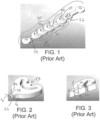
- FIG. 1 (Prior Art) shows a three-dimensional perspective view of a portion of a process fluid passage according to a prior art flow reactor
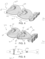
- FIG. 2 shows an individual chamber of the passage of FIG. 1
- FIG. 3 shows, in perspective view, a cross-section of the chamber of FIG. 2 .
- a flow reactor of the general type disclosed herein comprises a module having a process fluid passage 20 therein, the process fluid passage comprising an interior surface 22, the process fluid passage 20 further comprising a portion 30 thereof, which portion further comprises an input end 32 at which process fluid is to flow into the portion 30 during use and an output end 34 at which process fluid is to flow out of the portion 30 during use.
- the portion 20 also comprises a cross section 36 along the portion 30, delimited by the interior surface 22 of the passage 20 along the portion 30, the cross section 36 having a cross-sectional area and a cross-sectional shape 38, the cross-sectional area having multiple minima 40 along the passage 20 between the input end 32 and the output end 34.
- FIGS. 4 and 5 each show a three-dimensional perspective view of a portion of a process fluid passage in accordance with embodiments of the present disclosure
- FIG. 6 shows a cross-sectional view of a the passage of FIG. 5
- the reactor is characterized in that the portion 30 of the passage 20 has (1) a cross-sectional shape 38 which varies continually along the portion 30, (2) an interior surface 22 (along the portion 30) which includes either no pairs of opposing flat parallel sides 42 (as seen in FIG.
- the height of the portion 30 of the passage 20 may vary periodically with the chambers themselves, so that each successive chamber is essentially identical. Alternatively, a period of variation in the height of the portion 20 of the passage 20 may be shorter, in length along the portion 30, or longer, as in the embodiment of FIG. 5 . This results in obstacles 50 having varying height, as shown in the cross section of FIG. 6 .
- Cross sections of additional embodiments of portions 30 of passages 20 are shown in FIGS. 8-10 , with obstacles 50 of varying heights in the successive chambers 52 of FIG. 8 , or of the same height in the successive chambers 52 of FIG. 9 .
- Obstacles 50 also extend only partially across the height of the chambers 52, as shown in the embodiment of FIG. 10 . (Such obstacles effectively have only a single bypass path, albeit with a complex shape and flow pattern.) Variation in the height of the portion 30 of the passage 20 may also be asymmetrical, or the curvature of the successive chambers 52 may be asymmetrical. In the embodiment of FIG.7 and as seen in the figure, every other chamber 52 has a larger "bulge” (or a smaller radius of curvature) on the upper inside surface of the chamber (relative to the lower inside surface), while the remaining chambers 52 have a a larger "bulge” (or a smaller radius of curvature) on the lower insider surface (relative to the upper).
- a straight line 60 having a first endpoint located at a center of the entrance of the chamber 52 and a second endpoint locate at a center of the exit of the chamber is intersected by the obstacle 50.
- the obstacle 50 intersects not just the line 60 from the center point of the entrance to the center point of the exit of the chamber 52, but every line segment originating within the entrance of the chamber and ending within the exit of the chamber. In other words, desirably, there is no "line-of-sight" from the entrance to the exit of the chamber 52 even in the case that the obstacle extends only partially across the height of the chamber.
- the portions 30 of passages 20 herein include one or more bypass paths 64, as indicated, for example, in FIGS. 4 and 5 .
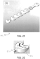
- the bypass paths 64 are paths positioned between the obstacle 50 and an inside surface of the associated chamber 52, and which lead around the obstacle 50. Such bypass paths 64 are distinguished from openings extending through an obstacle 50. Such openings 70 are seen in the embodiment of FIGS. 21-22 .
- the obstacle 50 has no openings extending through the obstacle 50.
- the one or more bypass paths 64 have a total cross-sectional area 66 greater than the total cross-sectional area 68 of the exit of the associated chamber.
- FIG. 11 shows a translucent perspective view of a portion of a process fluid passage in accordance with embodiments of the present disclosure
- FIG. 12 shows a cross-sectional view of a portion of a process fluid passage in accordance with embodiments of the present disclosure, of the type of the embodiment of FIG. 11 .
- one or more chambers 52 have both an obstacle 50 and a second obstacle 51 in the same chamber 52.
- the obstacle 50 and second obstacle 52 extend only partially across the height of the chamber 52 (as seen most clearly in FIG. 12 ), and desirably they are attached alternately to the "floor" and "ceiling" of the chamber 52.
- the obstacle or the second obstacle 52 may not, alone, intersect all lines of sight between the respective chamber's entrance and exit (or even the centerline between them), but it is desirable that they do so when considered together.
- the chambers 52 may have or almost have rotational symmetry, such that the height and width of the chambers are both considered instead as a diameter.
- FIGS. 13-18 each show a cut-away perspective view of a portion of a process fluid passage in which the portion 30 of the passage 20, as well as the successive chambers 51, have rotational symmetry. In embodiments such as these, three or more bypass paths may be used.
- the obstacles 50 comprise a flat or concave surface 72 aligned generally perpendicularly to the portion 30 of the process fluid passage 20.
- the surface 72 may preferably face in an upstream direction as shown in the embodiments of FIGS. 15, 16, and 18 , but in alternative embodiments may face in a downstream direction as in the embodiment of FIG. 17 .
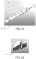
- FIGS. 19-32 show embodiments which were fabricated and performance tested in comparison to a reference embodiment (the embodiment of FIGS. 1-3 ).
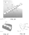
- the embodiment of FIG. 25 has chambers 52 similar to those of the embodiment of FIG. 19 , except raised “ceilings” and lowered “floors” 78, relative to the embodiment of FIG. 19 Results are shown in FIGS. 33-36 .
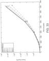
- FIGS. 33 and 34 are graphs of measured pressure drop.
- FIG. 33 results are from relatively larger scale passages
- FIG. 34 from relatively smaller scale passages.
- the numbers in the keys correspond to the numbers given for each embodiment in FIGS. 19-32 .
- all tested embodiments outperformed the reference embodiment in achieving lower pressure drop.
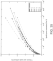
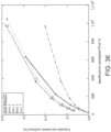
- FIGS. 35 and 36 are graphs of measured volumetric mass transfer coefficient as a function of specific power consumption, with FIG. 35 results from relatively larger scale passages and FIG. 36 results from relatively smaller scale passages. As seen in FIG. 35 , all tested embodiments other than number 2 and 5 outperformed the reference on this measure and in FIG. 36 all other than number 2. Accordingly, it is believed to be desirable to have no openings extending through the obstacles (as in embodiment number 2).
- bypass paths when there are two (or possibly more) in a chamber, separated by the obstacle by a distance of at least 2, 2.5, 3, 3.5 or even 4 times a maximum diameter of the exit of the chamber, unlike in embodiment number 5 in which a post or wedge 80 separates two bypass paths by only a short distance.
- the interior surface 22 (of the portion 30) passage 20 may include an internal screw thread structure 76 to impart an additional, helical motion to the fluid moving in the portion of the passage.
- Ranges can be expressed herein as from “about” one particular value, and/or to “about” another particular value. When such a range is expressed, embodiments include from the one particular value and/or to the other particular value. Similarly, when values are expressed as approximations, by use of the antecedent "about,” it will be understood that the particular value forms another aspect. It will be further understood that the endpoints of each of the ranges are significant both in relation to the other endpoint, and independently of the other endpoint.
Description
- The present disclosure relates generally to flow reactors and particularly to flow reactors having optimized channel structures.
- Process intensification aims to produce highly efficient reaction and processing systems using configurations that simultaneously significantly reduce reactor sizes and maximize mass- and heat-transfer efficiencies. Interest in and application of process intensification in chemical engineering is continually increasing because of the potential to transform large-scale, environmentally unfriendly industrial processes into smaller, safer, more energy-efficient and environmentally friendly processes.
- Process intensification consists in the development of novel apparatuses and techniques that, compared to those commonly used today, are expected to bring very significant, even order(s)-of-magnitude improvements in manufacturing and processing, in decreasing equipment-size/production-capacity ratio, energy consumption, and/or waste production, ultimately resulting in cheaper and sustainable technologies. Put another way, any chemical engineering development that leads to a substantially smaller, cleaner, and more energy-efficient technology is process intensification.
- The whole field of process intensification can generally be divided into two areas: process-intensifying equipment, such as novel reactors and intensive mixing, heat-transfer and mass-transfer devices; and process-intensifying methods, such as new or hybrid separations, integration of reaction and separation, heat exchange, or phase transition (in so-called multifunctional reactors), techniques using alternative energy sources (light, ultrasound, etc.), and new process-control methods (like intentional unsteady-state operation). Obviously, there can be some overlap. New methods may require novel types of equipment to be developed and vice versa, while novel apparatuses already developed sometimes make use of new, unconventional processing methods.
- In
US7939033 is disclosed a "microreactor" or micro- to milli-meter scale flow reactor with a characteristic channel design producing good mixing performance relative to pressure drop in a given channel or device. It would be desirable to achieve even better performance, however, such as equal or better mixing with lower pressure drop.US 2014/0290786 A1 relates to microfluidic channels and microfluidic devices. - The following presents a simplified summary of the disclosure in order to provide a basic understanding of some exemplary embodiments described in the detailed description.
- In the invention, a flow reactor comprises a module having a process fluid passage with an interior surface, a portion of the passage including a cross section along the portion having a cross-sectional shape, and a cross-sectional area with multiple minima along the passage. The cross-sectional shape varies continually along the portion and the interior surface of the portion includes either no pairs of opposing flat parallel sides or only pairs of opposing flat parallel sides which extend for a length of no more than 4 times a distance between said opposing flat parallel sides along the portion and the portion contains a plurality of obstacles distributed along the portion.
- The portion further comprises successive chambers each with a nozzle-like entrance and a narrowing exit.
- In some embodiments, a chamber of said successive chambers is nested with a next-succeeding chamber of said successive chambers such that the narrowing exit of the one chamber forms the nozzle-like entrance of the next adjacent succeeding chamber.
- In the invention, at least one of the plurality of obstacles is located within a first chamber and intersects a straight line having a first endpoint located at a center of the entrance of the first chamber and a second endpoint locate at a center of the exit of the first chamber. The flow reactor of the invention further comprises two or more obstacles in a single chamber, wherein the obstacles extend only partially across the height of the chamber.
- In some embodiments, the at least one of the plurality of obstacles intersects every straight line having a first end point within the entrance of the first chamber and a second endpoint within the exit of the first chamber .
- In some embodiments, the reactor having an obstacles in the first chamber has one or more bypass paths positioned between the at least one obstacle and an inside surface of the first chamber, i.e., around the at least one obstacle of the plurality of obstacles.
- In some embodiments, the at least one obstacle has no openings extending through said at least one obstacle.
- The above embodiments are exemplary and can be provided alone or in any combination with any one or more embodiments provided herein without departing from the scope of the disclosure. Moreover, it is to be understood that both the foregoing general description and the following detailed description present embodiments of the present disclosure, and are intended to provide an overview or framework for understanding the nature and character of the embodiments as they are described and claimed. The accompanying drawings are included to provide a further understanding of the embodiments, and are incorporated into and constitute a part of this specification. The drawings illustrate various embodiments of the disclosure, and together with the description, serve to explain the principles and operations thereof.
- These and other features, embodiments, and advantages of the present disclosure can be further understood when read with reference to the accompanying drawings:
-
FIG. 1 (Prior Art) shows a three-dimensional perspective view of a portion of a process fluid passage according to a prior art flow reactor; -
FIG. 2 (Prior Art) shows an individual chamber of the passage ofFIG. 1 ; -
FIG. 3 (Prior Art) shows, in perspective view, a cross-section of the chamber ofFIG. 2 ; -
FIG. 4 shows a three-dimensional perspective view of a portion of a process fluid passage in accordance with embodiments of the present disclosure; -
FIG. 5 shows a three-dimensional perspective view of a portion of a process fluid passage in accordance with embodiments of the present disclosure; -
FIG. 6 shows a cross-sectional view of a the passage ofFIG. 5 ; -
FIG. 7 shows a three-dimensional perspective view of a portion of a process fluid passage in accordance with embodiments of the present disclosure; -
FIG. 8-10 each show a cross-sectional view of a portion of a process fluid passage in accordance with embodiments of the present disclosure; -
FIG. 11 shows a translucent perspective view of a portion of a process fluid passage in accordance with embodiments of the present disclosure; -
FIG. 12 shows a cross-sectional view of a portion of a process fluid passage in accordance with embodiments of the present disclosure, such as the embodiment ofFIG. 11 ; -
FIG. 13 shows a cut-away perspective view of a portion of a process fluid passage in accordance with embodiments of the present disclosure; -
FIG. 14 shows an alternate cut-away perspective view of the portion of a process fluid passage in accordance with embodiments of the present disclosure ofFIG. 13 ; -
FIGS. 15-18 each show a cut-away perspective view of a portion of a process fluid passage in accordance with embodiments of the present disclosure; -
FIG. 19 shows a three-dimensional perspective view of a portion of a process fluid passage in accordance with embodiments of the present disclosure; -
FIG. 20 shows a cross-sectional view of a chamber of the passage ofFIG. 19 ; - FIG. shows a three-dimensional perspective view of a portion of a process fluid passage in accordance with embodiments of the present disclosure;
-
FIG. 22 shows an individual chamber of the passage ofFIG. 21 ; -
FIG. 23 shows a three-dimensional perspective view of a portion of a process fluid passage in accordance with embodiments of the present disclosure; -
FIG. 24 shows a cross-sectional view of a chamber of the passage ofFIG. 23 ; -
FIG. 25 shows a three-dimensional perspective view of a portion of a process fluid passage in accordance with embodiments of the present disclosure; -
FIG. 26 shows a three-dimensional perspective view of a portion of a process fluid passage in accordance with embodiments of the present disclosure; -
FIG. 27 shows a transparent plan view of a portion of the process fluid passage inFIG. 26 ; -
FIG. 28 shows a translucent perspective view of a portion of the process fluid passage inFIG. 26 ; -
FIG. 29 shows a three-dimensional perspective view of a portion of a process fluid passage in accordance with embodiments of the present disclosure; -
FIG. 30 shows a cross-sectional view of a chamber of the passage ofFIG. 29 ; -
FIG. 31 shows a plan view of a portion of a process fluid passage in accordance with embodiments of the present disclosure; -
FIG. 32 shows a plan view of a chamber of the passage ofFIG. 31 ; -
FIG. 33 is a graph of measured pressure drop as a function of flow rate as obtained from process fluid passages in accordance with embodiments of the present disclosure; -
FIG. 34 is a graph of measured pressure drop as a function of flow rate as obtained from process fluid passages in accordance with embodiments of the present disclosure; -
FIG. 35 is a graph of measured volumetric mass transfer coefficient as a function of specific power consumption as obtained from process fluid passages in accordance with embodiments of the present disclosure; -
FIG. 36 is a graph of measured volumetric mass transfer coefficient as a function of specific power consumption as obtained from process fluid passages in accordance with embodiments of the present disclosure; -
FIG. 37 each show a cut-away perspective view of walls of a portion of a process fluid passage in accordance with embodiments of the present disclosure; and -
FIG. 38 shows a cross-sectional plan view of a chamber of a portion of a process fluid passage in accordance with embodiments of the present disclosure. - Methods and apparatus will now be described more fully hereinafter with reference to the accompanying drawings in which exemplary embodiments of the disclosure are shown. Whenever possible, the same reference numerals are used throughout the drawings to refer to the same or like parts. However, this disclosure can be embodied in many different forms and should not be construed as limited to the embodiments set forth herein.
- The present disclosure relates generally to flow reactors employing modules similar to the ones disclosed in
US7939033 . If desired, the modules of the present disclosure may, however, depart from the generally planar geometry of that reference. - Flow modules having passages as disclosed herein may be formed by machining, molding, 3-D printing, and the like. Modules may be unitary (not able to be disassembled) or may consists of plates or other parts that are mechanically compressed or otherwise sealed together in a removable fashion.
-
FIG. 1 (Prior Art) shows a three-dimensional perspective view of a portion of a process fluid passage according to a prior art flow reactor, whileFIG. 2 (Prior Art) shows an individual chamber of the passage ofFIG. 1, and FIG. 3 (Prior Art) shows, in perspective view, a cross-section of the chamber ofFIG. 2 . - With respect to
FIGS. 1-3 , a flow reactor of the general type disclosed herein comprises a module having aprocess fluid passage 20 therein, the process fluid passage comprising aninterior surface 22, theprocess fluid passage 20 further comprising aportion 30 thereof, which portion further comprises aninput end 32 at which process fluid is to flow into theportion 30 during use and anoutput end 34 at which process fluid is to flow out of theportion 30 during use. - The
portion 20 also comprises across section 36 along theportion 30, delimited by theinterior surface 22 of thepassage 20 along theportion 30, thecross section 36 having a cross-sectional area and across-sectional shape 38, the cross-sectional area having multiple minima 40 along thepassage 20 between theinput end 32 and theoutput end 34. -
FIGS. 4 and 5 each show a three-dimensional perspective view of a portion of a process fluid passage in accordance with embodiments of the present disclosure, andFIG. 6 shows a cross-sectional view of a the passage ofFIG. 5 . With respect to the passages shown inFIGS. 4-6 , and generally with respect to embodiments of the present disclosure, the reactor is characterized in that theportion 30 of thepassage 20 has (1) across-sectional shape 38 which varies continually along theportion 30, (2) an interior surface 22 (along the portion 30) which includes either no pairs of opposing flat parallel sides 42 (as seen inFIG. 3 ) or only pairs of opposing flat parallel sides 42 which extend for a length of no more than 4 times a distance d between said opposing flat parallel sides 42 along the portion 30 (shown inFIG. 12 , discussed below), and (3) a plurality ofobstacles 50 positioned along (within) the portion between theinput end 32 and the output end 34 (in this case, in the form of a curved wall with a concave surface facing upstream. - Various forms of curvature may be used for the
interior surface 22 of theportion 30 of thepassage 20. As seen inFIG. 4 , the height of theportion 30 of thepassage 20 may vary periodically with the chambers themselves, so that each successive chamber is essentially identical. Alternatively, a period of variation in the height of theportion 20 of thepassage 20 may be shorter, in length along theportion 30, or longer, as in the embodiment ofFIG. 5 . This results inobstacles 50 having varying height, as shown in the cross section ofFIG. 6 . Cross sections of additional embodiments ofportions 30 ofpassages 20 are shown inFIGS. 8-10 , withobstacles 50 of varying heights in thesuccessive chambers 52 ofFIG. 8 , or of the same height in thesuccessive chambers 52 ofFIG. 9 .Obstacles 50 also extend only partially across the height of thechambers 52, as shown in the embodiment ofFIG. 10 . (Such obstacles effectively have only a single bypass path, albeit with a complex shape and flow pattern.) Variation in the height of theportion 30 of thepassage 20 may also be asymmetrical, or the curvature of thesuccessive chambers 52 may be asymmetrical. In the embodiment ofFIG.7 and as seen in the figure, everyother chamber 52 has a larger "bulge" (or a smaller radius of curvature) on the upper inside surface of the chamber (relative to the lower inside surface), while the remainingchambers 52 have a a larger "bulge" (or a smaller radius of curvature) on the lower insider surface (relative to the upper). - In the case as in the embodiment of
Figure 10 where theobstacle 50 extends only partially across the height of thechamber 52, astraight line 60 having a first endpoint located at a center of the entrance of thechamber 52 and a second endpoint locate at a center of the exit of the chamber is intersected by theobstacle 50. This insures that the less than full height obstacle is sufficiently tall to have a significant effect in displacing flow in the height direction. Desirably, theobstacle 50 intersects not just theline 60 from the center point of the entrance to the center point of the exit of thechamber 52, but every line segment originating within the entrance of the chamber and ending within the exit of the chamber. In other words, desirably, there is no "line-of-sight" from the entrance to the exit of thechamber 52 even in the case that the obstacle extends only partially across the height of the chamber. - The
portions 30 ofpassages 20 herein include one ormore bypass paths 64, as indicated, for example, inFIGS. 4 and 5 . Thebypass paths 64 are paths positioned between theobstacle 50 and an inside surface of the associatedchamber 52, and which lead around theobstacle 50.Such bypass paths 64 are distinguished from openings extending through anobstacle 50. Such openings 70 are seen in the embodiment ofFIGS. 21-22 . In embodiments more generally as seen in most other figures herein, theobstacle 50 has no openings extending through theobstacle 50. According to embodiments, as shown inFIG. 4 , the one ormore bypass paths 64 have a totalcross-sectional area 66 greater than the totalcross-sectional area 68 of the exit of the associated chamber. -
FIG. 11 shows a translucent perspective view of a portion of a process fluid passage in accordance with embodiments of the present disclosure whileFIG. 12 shows a cross-sectional view of a portion of a process fluid passage in accordance with embodiments of the present disclosure, of the type of the embodiment ofFIG. 11 . In embodiments as shown here, one ormore chambers 52 have both anobstacle 50 and asecond obstacle 51 in thesame chamber 52. Theobstacle 50 andsecond obstacle 52 extend only partially across the height of the chamber 52 (as seen most clearly inFIG. 12 ), and desirably they are attached alternately to the "floor" and "ceiling" of thechamber 52. In such embodiments, the obstacle or thesecond obstacle 52 may not, alone, intersect all lines of sight between the respective chamber's entrance and exit (or even the centerline between them), but it is desirable that they do so when considered together. - In some embodiments, the
chambers 52 may have or almost have rotational symmetry, such that the height and width of the chambers are both considered instead as a diameter.FIGS. 13-18 each show a cut-away perspective view of a portion of a process fluid passage in which theportion 30 of thepassage 20, as well as thesuccessive chambers 51, have rotational symmetry. In embodiments such as these, three or more bypass paths may be used. In embodiments, theobstacles 50 comprise a flat orconcave surface 72 aligned generally perpendicularly to theportion 30 of theprocess fluid passage 20. Thesurface 72 may preferably face in an upstream direction as shown in the embodiments ofFIGS. 15, 16, and 18 , but in alternative embodiments may face in a downstream direction as in the embodiment ofFIG. 17 . -
FIGS. 19-32 show embodiments which were fabricated and performance tested in comparison to a reference embodiment (the embodiment ofFIGS. 1-3 ). (The embodiment ofFIG. 25 haschambers 52 similar to those of the embodiment ofFIG. 19 , except raised "ceilings" and lowered "floors" 78, relative to the embodiment ofFIG. 19 Results are shown inFIGS. 33-36 . -
FIGS. 33 and34 are graphs of measured pressure drop.FIG. 33 results are from relatively larger scale passages,FIG. 34 from relatively smaller scale passages. The numbers in the keys correspond to the numbers given for each embodiment inFIGS. 19-32 . As seen inFIGS. 33 and34 , all tested embodiments outperformed the reference embodiment in achieving lower pressure drop. -
FIGS. 35 and36 are graphs of measured volumetric mass transfer coefficient as a function of specific power consumption, withFIG. 35 results from relatively larger scale passages andFIG. 36 results from relatively smaller scale passages. As seen inFIG. 35 , all tested embodiments other thannumber FIG. 36 all other thannumber 2. Accordingly, it is believed to be desirable to have no openings extending through the obstacles (as in embodiment number 2). Similarly, it is believed to be desirable to have the bypass paths, when there are two (or possibly more) in a chamber, separated by the obstacle by a distance of at least 2, 2.5, 3, 3.5 or even 4 times a maximum diameter of the exit of the chamber, unlike inembodiment number 5 in which a post orwedge 80 separates two bypass paths by only a short distance. - According to embodiments, the interior surface 22 (of the portion 30)
passage 20 may include an internalscrew thread structure 76 to impart an additional, helical motion to the fluid moving in the portion of the passage. - It will be appreciated that the various disclosed embodiments can involve particular features, elements or steps that are described in connection with that particular embodiment. It will also be appreciated that a particular feature, element or step, although described in relation to one particular embodiment, can be interchanged or combined with alternate embodiments in various non-illustrated combinations or permutations.
- It is to be understood that, as used herein the terms "the," "a," or "an," mean "at least one," and should not be limited to "only one" unless explicitly indicated to the contrary. Thus, for example, reference to "a component" includes embodiments having two or more such components unless the context clearly indicates otherwise.
- Ranges can be expressed herein as from "about" one particular value, and/or to "about" another particular value. When such a range is expressed, embodiments include from the one particular value and/or to the other particular value. Similarly, when values are expressed as approximations, by use of the antecedent "about," it will be understood that the particular value forms another aspect. It will be further understood that the endpoints of each of the ranges are significant both in relation to the other endpoint, and independently of the other endpoint.
- Unless otherwise expressly stated, it is in no way intended that any method set forth herein be construed as requiring that its steps be performed in a specific order. Accordingly, where a method claim does not actually recite an order to be followed by its steps or it is not otherwise specifically stated in the claims or descriptions that the steps are to be limited to a specific order, it is no way intended that any particular order be inferred.
- While various features, elements or steps of particular embodiments can be disclosed using the transitional phrase "comprising," it is to be understood that alternative embodiments, including those that can be described using the transitional phrases "consisting" or "consisting essentially of," are implied. Thus, for example, implied alternative embodiments to an apparatus that comprises A+B+C include embodiments where an apparatus consists of A+B+C and embodiments where an apparatus consists essentially of A+B+C.
Claims (13)
- A flow reactor comprising:a module having a process fluid passage therein, the process fluid passage comprising an interior surface, the process fluid passage further comprising a portion thereof which portion further comprises:wherein the flow reactor further comprises two or more obstacles in a single chamber; and, wherein the obstacles extend only partially across the height of the chamber.(1) an input end at which process fluid is to flow into the portion during use and(2) an output end at which process fluid is to flow out of the portion during use, and(3) a cross section along the portion delimited by the interior surface of the passage along the portion, the cross section having a cross-sectional area and a cross-sectional shape, the cross-sectional area having multiple minima along the passage between the input end and the output end, the passage characterized in that (1) the cross-sectional shape of the portion varies continually along the portion, (2) the interior surface of the portion includes either no pairs of opposing flat parallel sides or only pairs of opposing flat parallel sides which extend for a length of no more than 4 times a distance between said opposing flat parallel sides along the portion, and (3) the portion contains a plurality of obstacles positioned along the portion between the input end and the output end;wherein the portion further comprises successive chambers each with a nozzle-like entrance and a narrowing exit;wherein at least one of the plurality of obstacles is located within a first chamber and intersects a straight line having a first endpoint located at a center of the entrance of the first chamber and a second endpoint locate at a center of the exit of the first chamber;
- The flow reactor according to claim 1 wherein one chamber of said successive chambers is nested with a next-succeeding chamber of said successive chambers such that the narrowing exit of the one chamber forms the nozzle-like entrance of the next adjacent succeeding chamber.
- The flow reactor according to either claim 1 or claim 2 wherein the at least one of the plurality of obstacles intersects every straight line having a first end point within the entrance of the first chamber and a second endpoint within the exit of the first chamber.
- The flow reactor according to any of claims 1 to 3 having one or more bypass paths, positioned between the at least one obstacle and an inside surface of the first chamber, around the at least one obstacle of the plurality of obstacles.
- The flow reactor according to claim 4 wherein said one or more bypass paths have a total cross-sectional area greater than the total cross-sectional area of the exit of the first chamber.
- The flow reactor according to claim 4 wherein said at least one obstacle has one or more openings extending through said at least one obstacle.
- The flow reactor according to claim 4 wherein said at least one obstacle has no openings extending through said at least one obstacle.
- The flow reactor according to any of claims 1-7 wherein the plurality of obstacles comprises at least three or more obstacles.
- The flow reactor of any of claims 1-8 wherein the at least one of the plurality of obstacles comprises a flat or concave surface aligned generally perpendicularly to the process fluid passage.
- The flow reactor of claim 9 wherein the flat or concave surface faces in a downstream direction.
- The flow reactor of claim 9 wherein the flat or concave surface faces in an upstream direction.
- The flow reactor of claim of any of claims 1-8 wherein the at least one of the plurality of obstacles comprises a tapering elongated end pointing in a downstream direction.
- The flow reactor of claim of any of claims 1-8 wherein the at least one obstacle of the plurality of obstacles comprises a tapering elongated end pointing in an upstream direction.
Priority Applications (1)
| Application Number | Priority Date | Filing Date | Title |
|---|---|---|---|
| EP23197105.2A EP4268947A3 (en) | 2017-07-31 | 2018-07-31 | Improved process-intensified flow reactor |
Applications Claiming Priority (2)
| Application Number | Priority Date | Filing Date | Title |
|---|---|---|---|
| US201762539541P | 2017-07-31 | 2017-07-31 | |
| PCT/US2018/044572 WO2019028002A1 (en) | 2017-07-31 | 2018-07-31 | Improved process-intensified flow reactor |
Related Child Applications (2)
| Application Number | Title | Priority Date | Filing Date |
|---|---|---|---|
| EP23197105.2A Division-Into EP4268947A3 (en) | 2017-07-31 | 2018-07-31 | Improved process-intensified flow reactor |
| EP23197105.2A Division EP4268947A3 (en) | 2017-07-31 | 2018-07-31 | Improved process-intensified flow reactor |
Publications (2)
| Publication Number | Publication Date |
|---|---|
| EP3661640A1 EP3661640A1 (en) | 2020-06-10 |
| EP3661640B1 true EP3661640B1 (en) | 2023-10-25 |
Family
ID=63449644
Family Applications (2)
| Application Number | Title | Priority Date | Filing Date |
|---|---|---|---|
| EP18762656.9A Active EP3661640B1 (en) | 2017-07-31 | 2018-07-31 | Improved process-intensified flow reactor |
| EP23197105.2A Pending EP4268947A3 (en) | 2017-07-31 | 2018-07-31 | Improved process-intensified flow reactor |
Family Applications After (1)
| Application Number | Title | Priority Date | Filing Date |
|---|---|---|---|
| EP23197105.2A Pending EP4268947A3 (en) | 2017-07-31 | 2018-07-31 | Improved process-intensified flow reactor |
Country Status (7)
| Country | Link |
|---|---|
| US (2) | US11192084B2 (en) |
| EP (2) | EP3661640B1 (en) |
| JP (2) | JP7212671B2 (en) |
| KR (2) | KR20230148262A (en) |
| CN (4) | CN115193359B (en) |
| TW (1) | TWI826386B (en) |
| WO (1) | WO2019028002A1 (en) |
Families Citing this family (5)
| Publication number | Priority date | Publication date | Assignee | Title |
|---|---|---|---|---|
| CN115193359B (en) * | 2017-07-31 | 2023-09-29 | 康宁股份有限公司 | Improved Process Enhanced Flow Reactor |
| EP3939967A1 (en) | 2020-07-15 | 2022-01-19 | KRKA, d.d., Novo mesto | A continuous process for the preparation of (s)-methyl n-((2'-cyano-[1,1'-biphenyl]-4-yl)methyl)-n-pentanoylvalinate in a flow reactor |
| CN112403412A (en) * | 2020-09-29 | 2021-02-26 | 合肥通用机械研究院有限公司 | Micro-reactor and reinforced mixing structure for same |
| DE102021115994B3 (en) * | 2021-06-21 | 2022-12-08 | Institut für Bioprozess- und Analysenmesstechnik e.V. | Apparatus and method for mixing two liquids or pastes |
| CN115554943A (en) * | 2021-07-02 | 2023-01-03 | 中国石油化工股份有限公司 | Micro-reactor |
Family Cites Families (88)
| Publication number | Priority date | Publication date | Assignee | Title |
|---|---|---|---|---|
| JPS5211221B1 (en) * | 1969-03-17 | 1977-03-29 | ||
| US3927868A (en) * | 1974-05-28 | 1975-12-23 | Thomas B Moore | Static-type mixer, and receptacle and method of packaging utilizing same |
| US4087862A (en) * | 1975-12-11 | 1978-05-02 | Exxon Research & Engineering Co. | Bladeless mixer and system |
| JPS52151676A (en) * | 1976-06-11 | 1977-12-16 | Fuji Photo Film Co Ltd | Method and equipment for dispersing |
| JP2513475B2 (en) * | 1986-10-21 | 1996-07-03 | ノードソン株式会社 | Liquid mixing and ejection method and apparatus |
| DE10019759C2 (en) * | 2000-04-20 | 2003-04-30 | Tracto Technik | Static mixing system |
| DE10032059A1 (en) | 2000-07-05 | 2002-01-17 | Mir Chem Gmbh | Device for carrying out a catalytic tube reaction |
| SE520749C2 (en) | 2001-12-21 | 2003-08-19 | Tetra Laval Holdings & Finance | Static mixer for continuous mixing of one or more flows |
| US8206666B2 (en) * | 2002-05-21 | 2012-06-26 | Battelle Memorial Institute | Reactors having varying cross-section, methods of making same, and methods of conducting reactions with varying local contact time |
| JP2004024992A (en) | 2002-06-24 | 2004-01-29 | Atec Japan:Kk | Microreacter and chemical reaction method using the same |
| JP3888632B2 (en) * | 2003-03-26 | 2007-03-07 | 靖浩 堀池 | Micromixer, sample analysis kit and manufacturing method thereof |
| US20040228211A1 (en) | 2003-05-13 | 2004-11-18 | Koripella Chowdary R. | Internal micromixer |
| CN1833153B (en) | 2003-08-01 | 2012-04-04 | 贝洱两合公司 | Heat exchanger and method for the production thereof |
| PT103072B (en) | 2004-02-13 | 2009-12-02 | Faculdade De Engenharia Da Uni | MIXER IN NETWORK AND RESPECTIVE MIXING PROCESS |
| EP1944079B1 (en) | 2004-06-11 | 2012-05-30 | Corning Incorporated | Microstructure designs for optimizing mixing and pressure drop |
| JP4444018B2 (en) * | 2004-06-22 | 2010-03-31 | シャープ株式会社 | Microreactor |
| JP4454431B2 (en) * | 2004-08-13 | 2010-04-21 | アルプス電気株式会社 | plate |
| GB0420971D0 (en) | 2004-09-21 | 2004-10-20 | Imp College Innovations Ltd | Piping |
| JP4892183B2 (en) | 2004-10-08 | 2012-03-07 | 株式会社フジキン | Fluid mixing device |
| JP2006122736A (en) | 2004-10-26 | 2006-05-18 | Dainippon Screen Mfg Co Ltd | Channel structure and its manufacturing method |
| WO2007035074A1 (en) | 2005-09-26 | 2007-03-29 | Lg Chem, Ltd. | Stack type reactor |
| JP4598646B2 (en) | 2005-10-18 | 2010-12-15 | 学校法人早稲田大学 | Micro reactor |
| JP2007136322A (en) | 2005-11-17 | 2007-06-07 | Konica Minolta Medical & Graphic Inc | Micro-reactor increasing efficiency of diffusion and reaction of reactants and reaction method using it |
| JP2007190505A (en) * | 2006-01-20 | 2007-08-02 | Kao Corp | Micro fluid device |
| US7794136B2 (en) | 2006-05-09 | 2010-09-14 | National Tsing Hua University | Twin-vortex micromixer for enforced mass exchange |
| JP4677969B2 (en) | 2006-10-06 | 2011-04-27 | 株式会社日立プラントテクノロジー | Microreactor |
| TW200819387A (en) | 2006-10-19 | 2008-05-01 | Univ Yuan Ze | Micro-reacting device having a micro-channel flow-guiding block |
| JP2008114162A (en) | 2006-11-06 | 2008-05-22 | Dainippon Printing Co Ltd | Micro-reactor and its manufacturing method |
| EP2017000B1 (en) * | 2007-07-11 | 2012-09-05 | Corning Incorporated | Process intensified microfluidic devices |
| JP2009082803A (en) | 2007-09-28 | 2009-04-23 | Dainippon Printing Co Ltd | Microreactor and its manufacturing method |
| JP2009090248A (en) | 2007-10-11 | 2009-04-30 | Fuji Xerox Co Ltd | Structure having micro flow passage, its manufacturing method and microreactor |
| KR100898065B1 (en) | 2007-10-19 | 2009-05-15 | 송상섭 | Micro reactor |
| JP4877211B2 (en) | 2007-11-28 | 2012-02-15 | 大日本印刷株式会社 | Microreactor and manufacturing method thereof |
| KR100934267B1 (en) | 2008-02-04 | 2009-12-28 | 한국과학기술원 | Mixer and filter having a porous spiral structure, and microchannel device having the same |
| TW200940162A (en) | 2008-03-18 | 2009-10-01 | Jing-Tang Yang | A micromixer and microreactor with split-and-recombination and chaotic mechanisms |
| JP5504526B2 (en) | 2008-03-25 | 2014-05-28 | 学校法人加計学園 | Method of forming slag flow using a microreactor |
| TW200946914A (en) | 2008-05-02 | 2009-11-16 | Univ Nat Cheng Kung | Micro mixer initiative control mechanism for a structure that has both a blunt body and a concave-convex surface |
| US8277112B2 (en) | 2008-05-27 | 2012-10-02 | The Research Foundation Of State University Of New York | Devices and fluid flow methods for improving mixing |
| WO2010009239A2 (en) | 2008-07-18 | 2010-01-21 | 3M Innovative Properties Company | Tortuous path static mixers and fluid systems including the same |
| KR101003654B1 (en) | 2008-08-27 | 2010-12-23 | 삼성전기주식회사 | semiconductor package transfomer |
| US8430558B1 (en) | 2008-09-05 | 2013-04-30 | University Of Central Florida Research Foundation, Inc. | Microfluidic mixer having channel width variation for enhanced fluid mixing |
| EP2172260A1 (en) | 2008-09-29 | 2010-04-07 | Corning Incorporated | Multiple flow path microfluidic devices |
| EP2184103A1 (en) | 2008-11-11 | 2010-05-12 | Onea Engineering Austria GmbH | Modular reactor |
| SE534745C2 (en) | 2009-04-15 | 2011-12-06 | Alfa Laval Corp Ab | Flow Module |
| DE202010000262U1 (en) | 2009-05-12 | 2010-05-20 | Lonza Ag | Flow reactor with microchannel system |
| DE202009017416U1 (en) | 2009-05-12 | 2010-04-15 | Lonza Ag | Reactor and set of reactors |
| WO2010131297A1 (en) | 2009-05-14 | 2010-11-18 | 株式会社日立プラントテクノロジー | Microreactor system |
| RU2009120627A (en) * | 2009-05-29 | 2010-12-10 | Корнинг Инкорпорейтед (US) | MICRO-LIQUID FLOW CONTROLLED DEVICES |
| JP2011020044A (en) | 2009-07-15 | 2011-02-03 | Dainippon Printing Co Ltd | Microreactor and method of fabricating the same |
| JP2011036773A (en) | 2009-08-10 | 2011-02-24 | Hitachi Ltd | Reactor and reaction plant |
| TW201107092A (en) * | 2009-08-20 | 2011-03-01 | Cheng-Wei Su | Multiple-bump hand tool structure |
| GB0919702D0 (en) | 2009-11-11 | 2009-12-30 | Ashe Morris Ltd | Improved agitated cell reactor |
| KR101176175B1 (en) | 2010-07-30 | 2013-05-09 | 광주과학기술원 | Micro mixer and method for fabricating thereof |
| EP2452743A1 (en) | 2010-11-12 | 2012-05-16 | Lonza AG | Reactor for carrying out chemical reactions |
| TWI429484B (en) | 2010-12-31 | 2014-03-11 | Resi Corp | Continuous tubular reactor and corrugated tube for making the reactor |
| CN202096947U (en) | 2011-05-16 | 2012-01-04 | 利穗科技(苏州)有限公司 | Impinging stream multi-stage micro-reactor |
| CN102188943B (en) | 2011-05-16 | 2013-08-28 | 利穗科技(苏州)有限公司 | Impact current multistage micro reactor |
| CN202169168U (en) | 2011-05-16 | 2012-03-21 | 利穗科技(苏州)有限公司 | Chaos-type multi-stage vortex micro-reactor |
| CN102188944B (en) | 2011-05-16 | 2013-08-28 | 利穗科技(苏州)有限公司 | Chaotic multistage eddy current micro-reactor |
| US20140104975A1 (en) | 2011-05-31 | 2014-04-17 | Mikhail Sergeevich Chivilikhin | Twist flow microfluidic mixer and module |
| TW201302299A (en) | 2011-07-15 | 2013-01-16 | Univ Nat Cheng Kung | Micro-mixer |
| US20130021868A1 (en) | 2011-07-22 | 2013-01-24 | Doolin Michael B | Static Fluid Mixer and Method |
| CN102240535A (en) | 2011-08-01 | 2011-11-16 | 利穗科技(苏州)有限公司 | Caterpillar type microreactor |
| CN202191898U (en) | 2011-08-01 | 2012-04-18 | 利穗科技(苏州)有限公司 | Caterpillar type micro reactor |
| CN102247787A (en) | 2011-08-01 | 2011-11-23 | 利穗科技(苏州)有限公司 | Chaotic micro reactor |
| CN202191902U (en) | 2011-08-01 | 2012-04-18 | 利穗科技(苏州)有限公司 | Chaotic type microreactor |
| CN102350286B (en) | 2011-08-01 | 2013-11-27 | 利穗科技(苏州)有限公司 | Impact type microreactor |
| CN202191899U (en) | 2011-08-01 | 2012-04-18 | 利穗科技(苏州)有限公司 | Impact type microreactor |
| WO2013054180A1 (en) | 2011-10-14 | 2013-04-18 | Council Of Scientific & Industrial Research | Continuous modular reactor |
| CN102553482A (en) | 2012-02-24 | 2012-07-11 | 张端 | Novel backflow-type micro mixer |
| CN202527089U (en) | 2012-02-24 | 2012-11-14 | 张端 | Novel backflow type micro-mixer |
| EP2872901B1 (en) * | 2012-07-07 | 2021-02-17 | Creoptix AG | Flow conduit system for a biochemical sensor |
| CN203525623U (en) | 2012-12-21 | 2014-04-09 | 江苏大学 | Piezoelectric micromixer |
| KR101432729B1 (en) | 2012-12-24 | 2014-08-21 | 인하대학교 산학협력단 | Micromixer with circular chambers and crossing constriction channels |
| JP2014198324A (en) | 2013-03-29 | 2014-10-23 | ソニー株式会社 | Microfluidic channel and microfluidic device |
| CN103285798B (en) | 2013-06-27 | 2015-04-22 | 利穗科技(苏州)有限公司 | Multilayer multistage microreactor |
| CN103638853B (en) | 2013-11-11 | 2015-10-28 | 江苏大学 | A kind of S type passive type micro-mixer |
| CN103877905B (en) | 2013-11-11 | 2016-01-20 | 江苏大学 | A kind of passive type micro-mixer |
| KR20150105856A (en) | 2014-03-10 | 2015-09-18 | 연세대학교 산학협력단 | Micro Mixer Using Taylor Gortler Vortex and Manufacturing Method Thereof |
| CN104138728B (en) | 2014-04-17 | 2016-01-27 | 西北工业大学 | A kind of segmentation restructuring passive type micro-mixer of bridge architecture |
| CN104307413B (en) | 2014-09-11 | 2016-05-11 | 浙江工业大学 | T-shaped micro-mixer |
| CN204193922U (en) | 2014-10-27 | 2015-03-11 | 大连韦德生化科技有限公司 | A kind of microreactor device with drops micro-structural |
| CN204338128U (en) | 2014-12-18 | 2015-05-20 | 郑州大学 | Micro gas-liquid reactor and micro gas-liquid reaction unit |
| CN104525031B (en) | 2014-12-21 | 2016-07-06 | 北京工业大学 | A kind of passive type many internal rib formations annular micro-mixer |
| US9587545B2 (en) * | 2015-01-26 | 2017-03-07 | Caterpillar Inc. | Flow agitator |
| CN204429262U (en) | 2015-01-26 | 2015-07-01 | 深圳市一正科技有限公司 | Microreactor |
| US10912865B2 (en) * | 2016-07-22 | 2021-02-09 | Cornell University | Rapid prototyping and in vitro modeling of patient-specific coronary artery bypass grafts |
| CN115193359B (en) * | 2017-07-31 | 2023-09-29 | 康宁股份有限公司 | Improved Process Enhanced Flow Reactor |
-
2018
- 2018-07-31 CN CN202210868551.4A patent/CN115193359B/en active Active
- 2018-07-31 TW TW107126473A patent/TWI826386B/en active
- 2018-07-31 EP EP18762656.9A patent/EP3661640B1/en active Active
- 2018-07-31 KR KR1020237034161A patent/KR20230148262A/en active Application Filing
- 2018-07-31 CN CN202210863734.7A patent/CN115155480B/en active Active
- 2018-07-31 JP JP2020505369A patent/JP7212671B2/en active Active
- 2018-07-31 WO PCT/US2018/044572 patent/WO2019028002A1/en unknown
- 2018-07-31 KR KR1020207005861A patent/KR102588588B1/en active IP Right Grant
- 2018-07-31 US US16/635,069 patent/US11192084B2/en active Active
- 2018-07-31 CN CN202210865164.5A patent/CN115178206B/en active Active
- 2018-07-31 CN CN201880050026.3A patent/CN111225739B/en active Active
- 2018-07-31 EP EP23197105.2A patent/EP4268947A3/en active Pending
-
2021
- 2021-11-02 US US17/517,104 patent/US11679368B2/en active Active
-
2023
- 2023-01-13 JP JP2023003761A patent/JP2023040249A/en active Pending
Also Published As
| Publication number | Publication date |
|---|---|
| CN115155480A (en) | 2022-10-11 |
| CN111225739A (en) | 2020-06-02 |
| CN115178206B (en) | 2023-09-29 |
| KR102588588B1 (en) | 2023-10-12 |
| WO2019028002A1 (en) | 2019-02-07 |
| CN115155480B (en) | 2023-09-29 |
| KR20230148262A (en) | 2023-10-24 |
| CN115178206A (en) | 2022-10-14 |
| TW201929955A (en) | 2019-08-01 |
| US20220055009A1 (en) | 2022-02-24 |
| JP7212671B2 (en) | 2023-01-25 |
| CN111225739B (en) | 2022-08-09 |
| CN115193359B (en) | 2023-09-29 |
| CN115193359A (en) | 2022-10-18 |
| EP3661640A1 (en) | 2020-06-10 |
| JP2020529309A (en) | 2020-10-08 |
| JP2023040249A (en) | 2023-03-22 |
| TWI826386B (en) | 2023-12-21 |
| EP4268947A2 (en) | 2023-11-01 |
| US11679368B2 (en) | 2023-06-20 |
| EP4268947A3 (en) | 2024-01-17 |
| KR20200037319A (en) | 2020-04-08 |
| US11192084B2 (en) | 2021-12-07 |
| US20200246772A1 (en) | 2020-08-06 |
Similar Documents
| Publication | Publication Date | Title |
|---|---|---|
| EP3661640B1 (en) | Improved process-intensified flow reactor | |
| US8263006B2 (en) | Reactor with upper and lower manifold structures | |
| CN211886766U (en) | Rotational flow type micro-reaction channel, substrate, reactor and system | |
| WO2010141368A2 (en) | Honeycomb reactor or heat exchanger mixer | |
| CN111974290B (en) | Taiji-shaped passive micro mixer | |
| CN112403413A (en) | Integrated countercurrent strengthening microreactor | |
| CN204107488U (en) | Integrated micro-reaction device | |
| CN113893796B (en) | Chain type micro-reactor | |
| CN114887564A (en) | Micro-channel reactor | |
| CN113198402B (en) | Multi-stage series micro-reactor and fluid mixing method | |
| CN108548437B (en) | Bionic-based fishbone-type micro-staggered alveolar heat exchanger core and heat exchanger | |
| CN115318215B (en) | E-shaped microreactor channel structure | |
| CN116550245A (en) | Double-layer composite micro-reaction channel plate containing three-dimensional ladder channel and micro-channel reactor | |
| CN111398496A (en) | Micro gas chromatographic column in staggered array arrangement | |
| CN207300031U (en) | A kind of curved slab and the fluid interactive device using the curved slab | |
| TW202410963A (en) | Improved process-intensified flow reactor | |
| KR20090043439A (en) | Substrate and micro reactor comprising the same | |
| EP2506961A2 (en) | Honeycomb body u-bend mixers | |
| CN114160067A (en) | Combined baffle type microreactor | |
| PATEL et al. | HEAT EXCHANGE PROCESS INTENSIFICATION: REENGINEERING THE THINGS |
Legal Events
| Date | Code | Title | Description |
|---|---|---|---|
| STAA | Information on the status of an ep patent application or granted ep patent |
Free format text: STATUS: UNKNOWN |
|
| STAA | Information on the status of an ep patent application or granted ep patent |
Free format text: STATUS: THE INTERNATIONAL PUBLICATION HAS BEEN MADE |
|
| PUAI | Public reference made under article 153(3) epc to a published international application that has entered the european phase |
Free format text: ORIGINAL CODE: 0009012 |
|
| STAA | Information on the status of an ep patent application or granted ep patent |
Free format text: STATUS: REQUEST FOR EXAMINATION WAS MADE |
|
| 17P | Request for examination filed |
Effective date: 20200220 |
|
| AK | Designated contracting states |
Kind code of ref document: A1 Designated state(s): AL AT BE BG CH CY CZ DE DK EE ES FI FR GB GR HR HU IE IS IT LI LT LU LV MC MK MT NL NO PL PT RO RS SE SI SK SM TR |
|
| AX | Request for extension of the european patent |
Extension state: BA ME |
|
| DAV | Request for validation of the european patent (deleted) | ||
| DAX | Request for extension of the european patent (deleted) | ||
| STAA | Information on the status of an ep patent application or granted ep patent |
Free format text: STATUS: EXAMINATION IS IN PROGRESS |
|
| STAA | Information on the status of an ep patent application or granted ep patent |
Free format text: STATUS: EXAMINATION IS IN PROGRESS |
|
| 17Q | First examination report despatched |
Effective date: 20210125 |
|
| RIC1 | Information provided on ipc code assigned before grant |
Ipc: B01F 33/00 20220101ALI20230404BHEP Ipc: B01F 25/00 20220101ALI20230404BHEP Ipc: B01J 19/00 20060101AFI20230404BHEP |
|
| GRAP | Despatch of communication of intention to grant a patent |
Free format text: ORIGINAL CODE: EPIDOSNIGR1 |
|
| STAA | Information on the status of an ep patent application or granted ep patent |
Free format text: STATUS: GRANT OF PATENT IS INTENDED |
|
| INTG | Intention to grant announced |
Effective date: 20230515 |
|
| GRAS | Grant fee paid |
Free format text: ORIGINAL CODE: EPIDOSNIGR3 |
|
| GRAA | (expected) grant |
Free format text: ORIGINAL CODE: 0009210 |
|
| STAA | Information on the status of an ep patent application or granted ep patent |
Free format text: STATUS: THE PATENT HAS BEEN GRANTED |
|
| P01 | Opt-out of the competence of the unified patent court (upc) registered |
Effective date: 20230911 |
|
| AK | Designated contracting states |
Kind code of ref document: B1 Designated state(s): AL AT BE BG CH CY CZ DE DK EE ES FI FR GB GR HR HU IE IS IT LI LT LU LV MC MK MT NL NO PL PT RO RS SE SI SK SM TR |
|
| REG | Reference to a national code |
Ref country code: GB Ref legal event code: FG4D |
|
| REG | Reference to a national code |
Ref country code: CH Ref legal event code: EP |
|
| REG | Reference to a national code |
Ref country code: DE Ref legal event code: R096 Ref document number: 602018059998 Country of ref document: DE |
|
| REG | Reference to a national code |
Ref country code: IE Ref legal event code: FG4D |
|
| REG | Reference to a national code |
Ref country code: NL Ref legal event code: FP |
|
| REG | Reference to a national code |
Ref country code: LT Ref legal event code: MG9D |
|
| REG | Reference to a national code |
Ref country code: AT Ref legal event code: MK05 Ref document number: 1624131 Country of ref document: AT Kind code of ref document: T Effective date: 20231025 |
|
| PG25 | Lapsed in a contracting state [announced via postgrant information from national office to epo] |
Ref country code: GR Free format text: LAPSE BECAUSE OF FAILURE TO SUBMIT A TRANSLATION OF THE DESCRIPTION OR TO PAY THE FEE WITHIN THE PRESCRIBED TIME-LIMIT Effective date: 20240126 |
|
| PG25 | Lapsed in a contracting state [announced via postgrant information from national office to epo] |
Ref country code: IS Free format text: LAPSE BECAUSE OF FAILURE TO SUBMIT A TRANSLATION OF THE DESCRIPTION OR TO PAY THE FEE WITHIN THE PRESCRIBED TIME-LIMIT Effective date: 20240225 |
|
| PG25 | Lapsed in a contracting state [announced via postgrant information from national office to epo] |
Ref country code: LT Free format text: LAPSE BECAUSE OF FAILURE TO SUBMIT A TRANSLATION OF THE DESCRIPTION OR TO PAY THE FEE WITHIN THE PRESCRIBED TIME-LIMIT Effective date: 20231025 |
|
| PG25 | Lapsed in a contracting state [announced via postgrant information from national office to epo] |
Ref country code: AT Free format text: LAPSE BECAUSE OF FAILURE TO SUBMIT A TRANSLATION OF THE DESCRIPTION OR TO PAY THE FEE WITHIN THE PRESCRIBED TIME-LIMIT Effective date: 20231025 |
|
| PG25 | Lapsed in a contracting state [announced via postgrant information from national office to epo] |
Ref country code: ES Free format text: LAPSE BECAUSE OF FAILURE TO SUBMIT A TRANSLATION OF THE DESCRIPTION OR TO PAY THE FEE WITHIN THE PRESCRIBED TIME-LIMIT Effective date: 20231025 |
|
| PG25 | Lapsed in a contracting state [announced via postgrant information from national office to epo] |
Ref country code: LT Free format text: LAPSE BECAUSE OF FAILURE TO SUBMIT A TRANSLATION OF THE DESCRIPTION OR TO PAY THE FEE WITHIN THE PRESCRIBED TIME-LIMIT Effective date: 20231025 Ref country code: IS Free format text: LAPSE BECAUSE OF FAILURE TO SUBMIT A TRANSLATION OF THE DESCRIPTION OR TO PAY THE FEE WITHIN THE PRESCRIBED TIME-LIMIT Effective date: 20240225 Ref country code: GR Free format text: LAPSE BECAUSE OF FAILURE TO SUBMIT A TRANSLATION OF THE DESCRIPTION OR TO PAY THE FEE WITHIN THE PRESCRIBED TIME-LIMIT Effective date: 20240126 Ref country code: ES Free format text: LAPSE BECAUSE OF FAILURE TO SUBMIT A TRANSLATION OF THE DESCRIPTION OR TO PAY THE FEE WITHIN THE PRESCRIBED TIME-LIMIT Effective date: 20231025 Ref country code: BG Free format text: LAPSE BECAUSE OF FAILURE TO SUBMIT A TRANSLATION OF THE DESCRIPTION OR TO PAY THE FEE WITHIN THE PRESCRIBED TIME-LIMIT Effective date: 20240125 Ref country code: AT Free format text: LAPSE BECAUSE OF FAILURE TO SUBMIT A TRANSLATION OF THE DESCRIPTION OR TO PAY THE FEE WITHIN THE PRESCRIBED TIME-LIMIT Effective date: 20231025 Ref country code: PT Free format text: LAPSE BECAUSE OF FAILURE TO SUBMIT A TRANSLATION OF THE DESCRIPTION OR TO PAY THE FEE WITHIN THE PRESCRIBED TIME-LIMIT Effective date: 20240226 |