EP3650397B1 - Système pour déterminer l'état d'une grue à l'aide de capteurs optiques et/ou électromagnétiques - Google Patents
Système pour déterminer l'état d'une grue à l'aide de capteurs optiques et/ou électromagnétiques Download PDFInfo
- Publication number
- EP3650397B1 EP3650397B1 EP19207783.2A EP19207783A EP3650397B1 EP 3650397 B1 EP3650397 B1 EP 3650397B1 EP 19207783 A EP19207783 A EP 19207783A EP 3650397 B1 EP3650397 B1 EP 3650397B1
- Authority
- EP
- European Patent Office
- Prior art keywords
- boom
- crane
- captured image
- detected
- laser beam
- Prior art date
- Legal status (The legal status is an assumption and is not a legal conclusion. Google has not performed a legal analysis and makes no representation as to the accuracy of the status listed.)
- Active
Links
Images


Classifications
-
- B—PERFORMING OPERATIONS; TRANSPORTING
- B66—HOISTING; LIFTING; HAULING
- B66C—CRANES; LOAD-ENGAGING ELEMENTS OR DEVICES FOR CRANES, CAPSTANS, WINCHES, OR TACKLES
- B66C23/00—Cranes comprising essentially a beam, boom, or triangular structure acting as a cantilever and mounted for translatory of swinging movements in vertical or horizontal planes or a combination of such movements, e.g. jib-cranes, derricks, tower cranes
- B66C23/88—Safety gear
-
- B—PERFORMING OPERATIONS; TRANSPORTING
- B66—HOISTING; LIFTING; HAULING
- B66C—CRANES; LOAD-ENGAGING ELEMENTS OR DEVICES FOR CRANES, CAPSTANS, WINCHES, OR TACKLES
- B66C13/00—Other constructional features or details
- B66C13/16—Applications of indicating, registering, or weighing devices
-
- B—PERFORMING OPERATIONS; TRANSPORTING
- B66—HOISTING; LIFTING; HAULING
- B66C—CRANES; LOAD-ENGAGING ELEMENTS OR DEVICES FOR CRANES, CAPSTANS, WINCHES, OR TACKLES
- B66C13/00—Other constructional features or details
- B66C13/18—Control systems or devices
- B66C13/46—Position indicators for suspended loads or for crane elements
-
- G—PHYSICS
- G01—MEASURING; TESTING
- G01B—MEASURING LENGTH, THICKNESS OR SIMILAR LINEAR DIMENSIONS; MEASURING ANGLES; MEASURING AREAS; MEASURING IRREGULARITIES OF SURFACES OR CONTOURS
- G01B11/00—Measuring arrangements characterised by the use of optical techniques
- G01B11/02—Measuring arrangements characterised by the use of optical techniques for measuring length, width or thickness
- G01B11/03—Measuring arrangements characterised by the use of optical techniques for measuring length, width or thickness by measuring coordinates of points
-
- G—PHYSICS
- G01—MEASURING; TESTING
- G01S—RADIO DIRECTION-FINDING; RADIO NAVIGATION; DETERMINING DISTANCE OR VELOCITY BY USE OF RADIO WAVES; LOCATING OR PRESENCE-DETECTING BY USE OF THE REFLECTION OR RERADIATION OF RADIO WAVES; ANALOGOUS ARRANGEMENTS USING OTHER WAVES
- G01S17/00—Systems using the reflection or reradiation of electromagnetic waves other than radio waves, e.g. lidar systems
- G01S17/02—Systems using the reflection of electromagnetic waves other than radio waves
- G01S17/06—Systems determining position data of a target
- G01S17/08—Systems determining position data of a target for measuring distance only
-
- G—PHYSICS
- G01—MEASURING; TESTING
- G01S—RADIO DIRECTION-FINDING; RADIO NAVIGATION; DETERMINING DISTANCE OR VELOCITY BY USE OF RADIO WAVES; LOCATING OR PRESENCE-DETECTING BY USE OF THE REFLECTION OR RERADIATION OF RADIO WAVES; ANALOGOUS ARRANGEMENTS USING OTHER WAVES
- G01S17/00—Systems using the reflection or reradiation of electromagnetic waves other than radio waves, e.g. lidar systems
- G01S17/88—Lidar systems specially adapted for specific applications
- G01S17/89—Lidar systems specially adapted for specific applications for mapping or imaging
-
- G—PHYSICS
- G01—MEASURING; TESTING
- G01S—RADIO DIRECTION-FINDING; RADIO NAVIGATION; DETERMINING DISTANCE OR VELOCITY BY USE OF RADIO WAVES; LOCATING OR PRESENCE-DETECTING BY USE OF THE REFLECTION OR RERADIATION OF RADIO WAVES; ANALOGOUS ARRANGEMENTS USING OTHER WAVES
- G01S7/00—Details of systems according to groups G01S13/00, G01S15/00, G01S17/00
- G01S7/48—Details of systems according to groups G01S13/00, G01S15/00, G01S17/00 of systems according to group G01S17/00
- G01S7/481—Constructional features, e.g. arrangements of optical elements
- G01S7/4817—Constructional features, e.g. arrangements of optical elements relating to scanning
-
- G—PHYSICS
- G01—MEASURING; TESTING
- G01S—RADIO DIRECTION-FINDING; RADIO NAVIGATION; DETERMINING DISTANCE OR VELOCITY BY USE OF RADIO WAVES; LOCATING OR PRESENCE-DETECTING BY USE OF THE REFLECTION OR RERADIATION OF RADIO WAVES; ANALOGOUS ARRANGEMENTS USING OTHER WAVES
- G01S7/00—Details of systems according to groups G01S13/00, G01S15/00, G01S17/00
- G01S7/48—Details of systems according to groups G01S13/00, G01S15/00, G01S17/00 of systems according to group G01S17/00
- G01S7/497—Means for monitoring or calibrating
- G01S7/4972—Alignment of sensor
-
- G—PHYSICS
- G06—COMPUTING OR CALCULATING; COUNTING
- G06T—IMAGE DATA PROCESSING OR GENERATION, IN GENERAL
- G06T7/00—Image analysis
- G06T7/50—Depth or shape recovery
- G06T7/521—Depth or shape recovery from laser ranging, e.g. using interferometry; from the projection of structured light
-
- G—PHYSICS
- G06—COMPUTING OR CALCULATING; COUNTING
- G06T—IMAGE DATA PROCESSING OR GENERATION, IN GENERAL
- G06T7/00—Image analysis
- G06T7/60—Analysis of geometric attributes
- G06T7/62—Analysis of geometric attributes of area, perimeter, diameter or volume
-
- G—PHYSICS
- G06—COMPUTING OR CALCULATING; COUNTING
- G06T—IMAGE DATA PROCESSING OR GENERATION, IN GENERAL
- G06T7/00—Image analysis
- G06T7/70—Determining position or orientation of objects or cameras
-
- G—PHYSICS
- G06—COMPUTING OR CALCULATING; COUNTING
- G06T—IMAGE DATA PROCESSING OR GENERATION, IN GENERAL
- G06T7/00—Image analysis
- G06T7/90—Determination of colour characteristics
-
- H—ELECTRICITY
- H04—ELECTRIC COMMUNICATION TECHNIQUE
- H04N—PICTORIAL COMMUNICATION, e.g. TELEVISION
- H04N23/00—Cameras or camera modules comprising electronic image sensors; Control thereof
- H04N23/50—Constructional details
- H04N23/54—Mounting of pick-up tubes, electronic image sensors, deviation or focusing coils
-
- B—PERFORMING OPERATIONS; TRANSPORTING
- B66—HOISTING; LIFTING; HAULING
- B66C—CRANES; LOAD-ENGAGING ELEMENTS OR DEVICES FOR CRANES, CAPSTANS, WINCHES, OR TACKLES
- B66C23/00—Cranes comprising essentially a beam, boom, or triangular structure acting as a cantilever and mounted for translatory of swinging movements in vertical or horizontal planes or a combination of such movements, e.g. jib-cranes, derricks, tower cranes
- B66C23/18—Cranes comprising essentially a beam, boom, or triangular structure acting as a cantilever and mounted for translatory of swinging movements in vertical or horizontal planes or a combination of such movements, e.g. jib-cranes, derricks, tower cranes specially adapted for use in particular purposes
- B66C23/36—Cranes comprising essentially a beam, boom, or triangular structure acting as a cantilever and mounted for translatory of swinging movements in vertical or horizontal planes or a combination of such movements, e.g. jib-cranes, derricks, tower cranes specially adapted for use in particular purposes mounted on road or rail vehicles; Manually-movable jib-cranes for use in workshops; Floating cranes
- B66C23/42—Cranes comprising essentially a beam, boom, or triangular structure acting as a cantilever and mounted for translatory of swinging movements in vertical or horizontal planes or a combination of such movements, e.g. jib-cranes, derricks, tower cranes specially adapted for use in particular purposes mounted on road or rail vehicles; Manually-movable jib-cranes for use in workshops; Floating cranes with jibs of adjustable configuration, e.g. foldable
-
- B—PERFORMING OPERATIONS; TRANSPORTING
- B66—HOISTING; LIFTING; HAULING
- B66C—CRANES; LOAD-ENGAGING ELEMENTS OR DEVICES FOR CRANES, CAPSTANS, WINCHES, OR TACKLES
- B66C2700/00—Cranes
- B66C2700/03—Cranes with arms or jibs; Multiple cranes
- B66C2700/0321—Travelling cranes
- B66C2700/0357—Cranes on road or off-road vehicles, on trailers or towed vehicles; Cranes on wheels or crane-trucks
-
- G—PHYSICS
- G06—COMPUTING OR CALCULATING; COUNTING
- G06T—IMAGE DATA PROCESSING OR GENERATION, IN GENERAL
- G06T2207/00—Indexing scheme for image analysis or image enhancement
- G06T2207/10—Image acquisition modality
- G06T2207/10028—Range image; Depth image; 3D point clouds
Definitions
- Known cranes include a boom operably connected to a lower works.
- a mobile crane may include a telescoping boom connected to a mobile carrier
- a crawler crane may include a lattice boom connected to a crawler carrier
- a tower crane may include a boom, commonly referred to as a jib, connected to a tower (also referred to as mast).
- the known cranes also include one or more hoists configured to wind and unwind a rope suspended from the boom.
- the rope typically extends around one or more sheaves in a desired reeving.
- a lifting appliance such as a hook block, is secured to a free end of the rope.
- the hook block is configured to engage an object to be lifted by the crane.
- US Pat. Appl. Pubs. Nos. 2017/0217737 , 2018/0141787 , 2018/0141788 , 2018/0141789 and 2018/0143011 disclose various systems in which objects may detected in captured images, and a condition or status of a crane component may be determined based on an analysis of the detected object.
- a detected object may be a crane carrier or superstructure, and a slew angle or lift angle of the boom may be determined based on an analysis of the detected object.
- a number and type of crane statuses which may be determined may be limited by physical limitations, e.g., visibility from either end of a boom or from a remotely installed base crane or tower crane base structure.
- Said system includes a sensor assembly in the form of a laser displacement meter positioned to have a line of sight along a portion of the length of the boom.
- the laser displacement meter is configured to detect light transmission and output sensor information.
- there is a light emitter on the boom which emits a laser beam along a boom axis and a light receiver also positioned on the boom.
- the light receiver comprises photoreceptors having a plurality of light-receiving portions disposed perpendicularly to a horizontal bending axis of the boom. These photoreceptors are configured to detect the laser beam as it moves vertically with respect to the receiver due to the vertical deflection of the boom.
- the sensor information then output includes information regarding the detection of the laser beam by a light receiving portion.
- CN 103 398 668 A discloses a factory test bed for crane booms, having a light source and an array of light sensors.
- the present invention relates to a crane including a system for determining a crane status as set out in appended claim 1.
- the transmitter may emit a plurality of laser beams substantially in a vertical or horizontal plane, as desired.
- the transmitter may further include a diffraction device, such as one or more prisms, configured to diffract the laser beam into one or more beams in a vertical or horizontal plane, as desired.
- the transmitter may be rotatably mounted on the boom for movement through a range of angles in a vertical plane or horizontal plane, as desired.
- an angular position of the transmitter may be varied by a motor.
- a position of the diffraction device may be adjusted, for example, by a motor.
- the diffraction device may be rotated and/or linearly moved.
- the sensor assembly may be positioned on a lateral side of the boom, an underside of the boom, a top side of the boom.
- the system for determining the crane status may be operably connected to one or more crane components, and operation of the one or more crane components may be controlled based on the determined crane status.
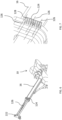
- FIG. 1 is a perspective view of a crane 10 having a system 110 for determining a crane status, according to an embodiment.
- the crane 10 includes lower works 12 and upper works 14 mounted on the lower works 12.
- the upper works 14 includes a rotating bed (not shown) mounted to the lower works 12 and a boom 16 mounted to the rotating bed so that the boom 16 may rotate with the rotating bed relative to the lower works.
- An operator's cab 18 may also be mounted on the rotating bed.
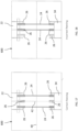
- a sensor assembly 114 may include a transmitter 122 and a receiver 124.
- the transmitter 122 is configured to emit electromagnetic radiation.
- the transmitter 122 may include a laser configured to emit at least one laser beam 126.
- the receiver 124 may be configured to detect the laser beam 126 incident on a surface thereof.
- the receiver 124 may be formed generally as a plate and include an array of photosensors 128, such as photodiodes, light dependent resistors, and the like.
- a position of individual photosensors 128 may be known and stored, for example, in the memory.
- FIG. 3 is a plan view showing an arrangement of the photosensors 128 according to an embodiment.
- the transmitter 122 and the receiver 124 may be spaced apart along a length direction 'L' of the boom 16. In one embodiment, the transmitter 122 and the receiver 124 may be positioned on a lateral side surface of the boom 16. In one embodiment, the boom 16 may be a telescoping boom, but is not limited thereto. In one embodiment, the transmitter 122 may be positioned at or near a boom tip 22 and the receiver 124 may be positioned on a different telescoping section of the boom 16.
- the system 110 is configured to determine at least one crane status based on sensor information received from the sensor assembly 114.
- the determined crane status may be, for example, side boom deflection (also referred to as horizontal boom deflection) and/or, in some embodiments, vertical boom deflection.
- the system 110 may determine whether such a crane status is present, and/or a measurement or estimate of the extent of the crane status.
- the laser beam 126 may be incident on a surface of the receiver 124 at an initial position and detected by a photosensor 128.
- the position of the laser beam 126 on the receiver 124 changes.
- the laser beam 126 may move horizontally (i.e., in a transverse, or width direction of the boom) as the boom 16 deflects horizontally.
- the laser beam 126 may move vertically (i.e., in a height direction of the boom) as the boom 16 deflects vertically.
- the sensor information may indicate whether the laser beam 126 is incident upon the receiver, and optionally, which photosensor 128 detected the laser beam 126.
- the system 110 may determine a position of the laser beam 126 on the receiver 124.
- the system 110 may determine whether side boom deflection is occurring based on a change in position of the laser beam 126 on the receiver 124.
- a scale factor may be known, for example, through calibration, and stored in the memory. The system 110 may then calculate the extent of the side deflection based on the detected change in position of the laser beam 126 on the receiver 124 and the scale factor.
- the laser beam 126 moves to a position offset from the receiver 124 if side deflection of the boom 16 exceeds a threshold amount.
- the sensor assembly 114 may provide sensor information indicating that the laser beam 126 is not detected.
- the sensor assembly 114 may not provide sensor information, and the system 110 may determine that side boom deflection exceeds the threshold extent in response to not receiving sensor information, for example, over a predetermined length of time.
- the sensor assembly 114 may be configured, such that the laser beam 126, with the boom 16 in an undeflected condition, is not incident upon the receiver 124, but becomes incident upon the receiver 124 in response to boom deflection beyond a threshold extent.
- multiple laser beams 126 may be incident upon the receiver 124 and may be detected by one or more photosensors 128.
- the different laser beams 126 may be emitted from transmitters 122 positioned at different lengths along the boom 16, for example.
- FIG. 5 illustrates an example of a boom 16 in a vertically deflected condition, according to an embodiment.
- such vertical deflection of the boom 16 may cause the laser beam 126 to become vertically offset from the receiver 124, and thus, not be detected by a photodetector 128.
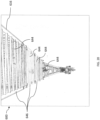
- FIG. 6 shows an example of the crane 10 having the system 110 for determining a crane status in which the sensor assembly 114 includes another embodiment of a transmitter 222.
- the transmitter 222 is configured to emit a plurality of laser beams 126 extending substantially in a vertical plane in the direction of the laser beams 126.
- FIG. 7 is an enlarged view of the receiver 124 toward which the plurality of laser beams 126 are generally directed.
- at least one laser beam 126 will remain incident upon the receiver 124 through a range of vertical boom deflections, when side deflection is within a predetermined threshold, and is detectable by a photosensor 128.
- the laser beams 126 will become horizontally offset from the receiver 124 when horizontal deflection of the boom 16 exceeds the predetermined range, and thus, the laser beams 126 will not be detected by a photosensor 128.
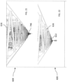
- FIG. 8 shows an example of the crane 10 having the system 110 for determining a crane status in which the sensor assembly 114 includes another embodiment of a transmitter 322.
- the transmitter 322 may include a diffraction device (not shown), such as one or more prisms or diffraction grating, configured to diffract a laser beam 126 along a line extending substantially in a vertical plane or horizontal plane, as desired, toward the receiver 124. That is, a laser beam 126 may be diffracted by the diffraction device to extend in a direction to be incident upon the receiver 124. For example, the laser beam 126 may be diffracted substantially in the vertical plane to become incident upon the receiver 124 when horizontal deflection is within a predetermined range.
- a diffraction device such as one or more prisms or diffraction grating
- horizontal deflection may be measured.
- the laser beam 126 may be diffracted substantially in a horizontal plane to be incident upon the receiver 124 when vertical deflection is within a predetermined range.
- vertical deflection may be measured.
- the diffraction device may split the laser beam 126 into multiple laser beams in a known manner, the laser beams extending substantially in the vertical plane or the horizontal plane, as desired.
- a scanning operation may be performed by adjusting the diffraction device to direct the laser beam 126 through a range of angles in the vertical plane and/or horizontal plane as desired.
- FIG. 9 is an enlarged view of the receiver 124 toward which the plurality of laser beams 126 are generally directed.
- the system 110 may determine the horizontal boom deflection based on sensor information indicating whether a laser beam 126 is detected by a photodetector 128 in the manner detailed above. With diffraction known, either horizontally, vertically, or both, as well as a position of the laser beam 126 on the receiver 124, the horizontal deflection, vertical deflection, or both, may be determined.
- the diffraction device may split the laser beam 126 into multiple beams, for example, due to crane jittering, shivering, oscillation and the like.
- the diffracted laser beam or beams 126 may then be detected along a line of reference points and/or on the array of photosensors 128 located on the receiver 124.
- the transmitter 122 may be rotatably mounted on the boom 16 to perform a scanning operation.
- the transmitter 122 may be rotated by a motor through a range of angles in the vertical plane. Accordingly, the laser beam 126 would become incident on receiver 124 and detected by a photosensor 128 during at least a portion of the scanning operation, when side boom deflection is within the predetermined threshold.
- a rated capacity limiter (RCL) of the crane may perform calculations to predict the vertical deflection of the boom 16.
- the transmitter 122 may be rotatably mounted on the boom 16 and operably connected to the system 110 and/or the RCL.
- the system 110 or RCL may control the motor (not shown) to adjust an angular position of the transmitter based on the predicted vertical boom deflection so that the laser beam 126 remains incident upon the receiver 124 through a range of vertical boom deflections, when the horizontal deflection is within predetermined limits.
- the system 110 may include a sensor assembly 414 in the form of an image capture device, such as a digital camera, which incorporates an image sensor configured to detect, for example, electromagnetic radiation, such as light. Information from the image sensor may be used for example, by the computer 112, to generate and capture an image within a field of view of the image capture device.
- Suitable cameras include, but are not limited wide-angle, stereo, telephoto, zoom, video and similar known cameras configured to capture an image in a field of view.
- the system 110 may include a sensor assembly 514 formed as a LiDAR assembly.
- the LiDAR assembly 514 is configured to perform surveying operations and includes a transmitter configured to emit electromagnetic radiation, such as one or more laser beams, for example, as pulsed beams, and a receiver which includes a sensor, such as a photosensor, configured to receive reflected laser beams (i.e., reflections of the one or more laser beams emitted from the transmitter).
- the LiDAR assembly 514 may then provide sensor information indicative of the received reflected laser beams to the computer 112.
- the computer 112 may then generate a three-dimensional image of the captured field of view, i.e., a captured image, of the LiDAR assembly 514.
- the computer 112 and LiDAR assembly 514 may be integrated.
- the system 110 may include any one of the sensor assemblies 114, 414, 514, various combinations of the sensor assemblies (e.g., any two of the assemblies), or all of the sensor assemblies 114, 414, 514.
- multiple sensor assemblies of the same type may be provided as well. Accordingly, in some embodiments, multiple and/or different sensor assemblies may provide sensor information to the computer 112.
- the system 110 is configured to detect one or more objects in the captured image using one or more known, suitable, object detection algorithms which will be appreciated by those having ordinary skill in the art.
- object detection algorithms may relate to, for example, edge detection, brightness contrast, pixel density, blob detection, motion detection, and the like.
- the object detection algorithms may be feature-based or incorporate known deep learning techniques.
- the detected objects may include, for example, a crane component, a load being lifting by the crane, worksite obstacles adjacent to the crane, and a horizon.
- the crane components which may be detected include, but are not limited to, the boom 16, a flexible member 24 suspended from the boom 16 ( FIGS. 10 and 11 ), sheaves 26 ( FIGS. 17-19 ) around which the flexible member 24 may extend, anti-two block ("ATB") detection components 28, 30, 32 ( FIGS. 15 and 16 ), a lifting appliance 34 ( FIGS. 10 and 11 ), a tower crane mast (also referred to as a tower) (not shown), a tower crane trolley 746 ( FIGS. 21 and 22 ), a trailing boom dolly (not shown), boom attachments 38 such as a jib extension ( FIG. 19 ), support pendants (not shown), and a marker (not shown) on any of the crane components.
- ATB anti-two block
- the detected boom 16 may be any of a telescoping boom, lattice boom (616 in FIGS. 20-22 ), or tower crane jib (716 in FIG. 23 ).
- individual sections of the boom 16 may be detected, including telescoping sections or lattice sections.
- individual cords of a lattice boom or jib section may be detected.
- the boom tip 22 may be detected on the boom 16 as well.
- a stop block also referred to as a mousetrap
- the flexible member 24 may be, for example, a rope or cable. Depending on the resolution of the captured image, individual components of the flexible member 24 may be detected as well, such as strands and/or wires.
- the ATB components which may be detected include, for example, an ATB switch 28, an ATB weight 30, an ATB flag (not shown), and an ATB chain 32.
- the detected lifting appliance 34 may be, for example, a hook-block or a headache ball.
- the marker (not shown) may be, for example, a particular color or coating, shape, or pattern, for example, a QR code, a bar code, or other pattern which may be detected in the captured and recognized by way of analyzing the captured image. It is envisioned that other objects, including other crane components generally positioned along, connected to, or formed integrally with the boom 16 or tower crane mast may be detected as well.
- the system 110 is configured to analyze the captured image and/or the detected object to determine one or more parameters of the detected object within the captured image.
- a parameter may include, for example, a position of the detected object in the captured image, a change in position of the detected object with respect to time in a series of captured images, a relative position of one or more detected objects including a distance between the detected object and a reference point in the captured image, one or more dimensions of the detected object in the captured image, an orientation, a direction of extension, and/or a size, shape, color or pattern of the detected object in the captured image.
- the parameter within the captured image may be determined, for example, by counting pixels within the captured image or by measurements taken when a physical size of the captured image is known.
- the reference point may be, for example a center point, a vertical midline, a horizontal midline, a boundary of the captured image, an initial position of the detected object, a predetermined threshold position, another detected object within the captured image, or any other suitable reference point or line.
- the reference point may be stored in the memory and/or provided in the captured image.
- the position of the reference point may be known and stored in the memory as well.
- the crane status may be determined based on the determined parameters within the captured image.
- the system 110 is also configured to analyze the captured image, for example, by analyzing the determined parameters within the captured image, to obtain one or more actual parameters of the detected object and/or in the captured image, an identity of the detected object, and/or a crane status.
- the system 110 may analyze the captured image by way of an image/parameter compare technique which includes comparing one or more of the parameters of the detected object within the captured image to one or more known corresponding parameters of a known corresponding object in one or more stored images which may be stored in the memory.
- actual parameters, a crane status, and/or a crane component identity of the corresponding object in the one or more stored images may be known and stored as additional information with the stored image.
- the stored images may also represent expected crane statuses, including expected positions or changes in position of known crane components.
- a detected crane component in a captured image may be identified as corresponding to a known crane component, such as, but not limited to, a boom tip, a flexible member, a boom section, and the like, based on the additional information.
- the identification may be based on, for example, a parameter of the detected object in the captured image, such as size, shape or particular dimension of the detected object.
- the system 110 is configured to count the number of detected objects, and thus, may count a number of detected objects that have been identified as corresponding to a particular crane component.
- the additional information associated stored with the stored image may be associated with the detected object in the captured image.
- the actual parameters may refer to, for example, an actual measurement, dimension, position, distance and the like in the crane work environment. In this manner, actual parameters may be determined.
- the captured image and the one or more objects detected therein maybe compared to one or more stored images by superimposing one over the other, and comparing parameters of a detected object, for example, size, shape, dimensions, to those of a corresponding object in the stored images.
- the system 110 may analyze the captured image by using a scale factor technique, which includes applying a scale factor to one or more of the parameters of detected objects in the captured image to calculate an actual parameter.
- the scale factor may be determined, for example, by a calibration process in which actual parameters for detected objects are known and a ratio between the actual parameters and the parameters in the captured image may be determined.
- the scale factor may be stored in the memory.
- the actual parameters obtained in the calibration process may be stored in a table in the memory with corresponding parameters from the captured image.
- applying the scale factor includes looking up a parameter of the detected object in the captured image in the table to determine the actual parameter of the detected object.
- the actual parameter may be determined by a calculation based on the parameter within the captured image and the scale factor.
- the system 110 may determine one or more actual parameters of the detected object based on the sensor information received from the LiDAR assembly 514, e.g., sensor information obtained in a LiDAR surveying operation. This may be referred to herein as the LiDAR information technique. For example, based on the time between the transmitter 522 emitting a laser beam 126 and receipt of the reflected laser beam at the receiver 524, a distance to a detected object from the LiDAR assembly 514 may be determined.
- the system 110 may carry out various calculations based on trigonometric and/or geometric functions to determine, for example, an actual position of the detected object relative to a reference point (such as the LiDAR assembly 514), an actual distance between the detected object and a reference point or other detected object, and other relevant, suitable measurements.
- a reference point such as the LiDAR assembly 514
- the system 110 is configured to determine the crane status based on the one or more detected objects. In one embodiment, system 110 may determine the crane status based on the one or more detected objects and one or more of parameters of the detected objects in the captured image. In one embodiment, the system 110 may determine the crane status based on the one or more detected objects, one or more of the parameters of the detected objects in the captured image, and an analysis of the captured image and/or the one or more detected objects in the captured image.
- the crane status and the one or more actual parameters may be one and the same.
- the crane status and the one or more parameters of the detected object in the captured image may be one and the same, i.e., the crane status may be a parameter of a detected object in the captured image, for example, the position or distance of a detected object relative to a reference point or other detected obj ect.
- the crane status may include, for example: vertical boom deflection; side (or horizontal) boom deflection; boom length; boom section length, number of boom sections, type of boom sections, boom attachment installation condition and position (e.g., stowed, extended, not installed); boom attachment length; boom attachment offset; ATB component status including installation, correct positioning, condition, relative positioning; ATB status of the crane; reeving conditions including number of flexible member lines reeved, optimal reeving configuration, retaining pin installation status, sheave rotation; telescopic pick point; flexible member condition; pendant rope length; correct positioning of crane components; number of falls; number of flexible members; differences in construction from desired or expected construction; trolley position; tower crane mast deflection; tower crane mast twist; boom twist; load sway; trailing boom monitoring; jib rigging mode; and flexible member speed.
- FIGS. 10-22 show various examples of crane statuses which may be determined by the system 110. However, these examples are not exhaustive, and it will be appreciated that other crane conditions not shown in the figures or specifically identified in the following examples may be determined as well, based on the detection of objects in captured images described herein.
- FIGs 10-23 and FIG 25 relate to embodiments which do not form part of the present invention.
- FIG. 10 is a representation of a captured image 600, generated, for example, by the computer 112 based on sensor information from the sensor assembly 414 or the sensor assembly 514. That is, the captured image 600 may be an optical image from an image captured device such as a camera, or a LiDAR image from the LiDAR assembly 514. According to an embodiment, the system 110 may detect one or more objects in the captured image, such as the boom tip 22. In one embodiment, the system 110 may superimpose, or store in the memory, horizontal and vertical reference lines 40, 42 at known reference positions.
- FIG. 11 is another representation of the captured image 600 in which the boom 16 is vertically deflected.
- Vertical deflection of boom tip 22 may be determined in the manner described above with respect to FIG. 10 .
- the vertical deflection may be determined as the change in vertical distance of the boom tip 22 from the horizontal midline 40 from the initial undeflected position (D1 in FIG. 10 ) to the deflected position (D2 in FIG. 11 ).
- FIG. 12 is a representation of a captured image 600 in which the boom 16 is horizontally (or side) deflected.
- the system 110 may detect an object, such as the boom tip 22, and determine one or more parameters of the detected object in the captured image 600, such as a horizontal position or change in position of the boom tip 22, and/or a distance of the boom tip 22 from a reference point, such the vertical reference line 42.
- the system 110 may analyze the captured image 600 and/or the detected object, such as the boom tip 22, using any of the image/parameter compare, scale factor or LiDAR information techniques described herein to determine the horizontal deflection of the boom 16 as the crane status. It is understood that vertical and horizontal boom deflection, as well as other crane statuses described below may be determined from the same captured image 600.
- the system 110 may analyze the captured image 600, and/or the detected object, such as the boom tip 22, using any of the image/parameter compare, scale factor or LiDAR information techniques above to determine the boom length as the crane status.
- a boom length may be determined in the manner above for each of the one or more determined parameters. The boom lengths may then be averaged to produce a single boom length value.
- the present disclosure is not limited to such a technique, and the boom length may be determined using only one parameter in some embodiments.
- the system 110 may detect one or more boom sections of the boom 16 in the captured image, including the ends of the boom section. The system 110 then determine a length of the boom section using any one or more the of the techniques described herein.
- FIG. 15 is a representation of a captured image 600 in which an ATB condition may be monitored when the boom 16 is in an extended position
- FIG. 16 is a representation of a captured image 600 in which the ATB condition may be monitored when the boom 16 is in a retracted position.
- the system 110 may detect one or more objects in the captured image 600, such as various ATB components, including, but not limited to an ATB switch 28, an ATB weight 30, ATB flag (not shown) and an ATB chain 32.
- the system 110 may determine one or more parameters of the detected objects, such as the position, position relative to a reference point, size, shape, color, pattern, dimensions, and the like, of the various ATB components 28, 30, 32.
- the system 110 may analyze the captured image 600 and/or the various components 28, 30, 32, using any of the aforementioned image/parameter compare, scale factor and/or LiDAR information techniques, as appropriate. Accordingly, in one embodiment, the system 110 may determine which ATB components are installed by identifying the detected objects, if the ATB are correctly positioned and dimensioned (e.g., correct length), and if the ATB components are in an undesired operating condition (e.g., tangled), as a crane status.
- the system 110 may determine which ATB components are installed by identifying the detected objects, if the ATB are correctly positioned and dimensioned (e.g., correct length), and if the ATB components are in an undesired operating condition (e.g., tangled), as a crane status.
- the system 110 may determine an ATB status of crane. For example, the system 110 may detect one or more objects in the captured image 600, such as the lifting appliance 34 and the boom tip 22. The system 110 may determine one or more parameters of the detected objects in the captured image 600, such as a position, distance or change in distance between the detected lifting appliance 34 and boom tip 22. In one embodiment, the system 110 may determine an ATB condition as the crane status based on the one or more parameters of the detected objects in the captured image 600. Alternatively, or in addition, the system 110 may determine an ATB condition as the crane status based on an analysis of the captured image 600 and/or the detected objects, using any of the aforementioned image/parameter compare, scale factor or LiDAR information techniques.
- FIG. 17 is a representation of a captured image 600 in which a correct reeving is provided
- FIG. 18 is a representation of a captured image 600 in which an incorrect reeving is provided, according to embodiments.
- the system 110 may detect one or more objects in the captured image 600, such as the flexible member 24 (including individual lines of the flexible member 24) and one or more sheaves 26 at the boom tip 22 and/or the lifting appliance 34.
- the system 110 may determine one or more parameters of the detected objects in the captured image 600, such as the positions, relative positions, shapes and/or sizes of the flexible member 24 and the sheaves 26.
- the system 110 may analyze the captured image 110 and/or the detected objects, such as the flexible member 24 and sheaves 26, using any of the aforementioned image/parameter compare, scale factor, or LiDAR information techniques. From the analysis, the system 110 may identify and count individual lines of the flexible member 24 and the sheaves 26. Accordingly, the system 110 may determine the number of lines 24 reeved as the crane status.
- the system 110 may also determine whether the detected reeving is an optimal reeving. For example, system 110 may store images or actual parameters of optimal reeving configurations for a given number of lines of the flexible member 24. With the number of detected lines determined in the manner above, and various parameters in the captured image 600 determined in the manner above, including the relative positions of the detected lines 24 and the sheaves 26, the system 110 may determine whether the detected reeving in the captured image 600 corresponds to an optimal reeving stored in the memory. Accordingly, the system 110 may determine a crane status as having an optimal or non-optimal reeving. In a similar manner, the system 110 may determine whether the lines 24 are correctly reeved.
- the system 110 may also determine whether various components of the reeving, such as retaining pins, are present in the captured image, for example, by identifying the detected objects as corresponding to particular components as detailed above and comparing the detected (and identified) objects to a corresponding list of expected objects stored in the memory. Alternatively, or in addition, a stored image having expected objects identified therein may be compared to the captured image 600 to determine if the expected objects are present in the captured image. The system 110 may also determine if the detected objects are correctly positioned in a similar manner.
- the system 110 may determine the crane status to be a status of the sheaves 26, for example, as locked or turning. For example, the system 110 may analyze the detected sheaves 26 by comparing a current captured image 600 to previously captured images 600 to determine a change in position of the sheave 26 with respect to time.
- the sheave 26 may have one or more markers (not shown) thereon which may be detected in the captured image 600. The system 110 may determine if a position of the marker has changed in a manner indicative of sheave rotation.
- the detected marker may be identified as corresponding to a known marker having additional information associated therewith stored in the memory. The additional information may include rotational position information.
- Different markers may be included on the sheave 26 having additional information that is indicative of different rotational positions of the sheave 26.
- the system 110 may determine a rotational speed of the sheave 26, and in turn, a speed of the flexible member 24 on the sheave 26.
- FIG. 19 is a representation of a captured image 600 in which an end of the boom 16 is positioned, according to an embodiment.
- the system 110 may detect one or more objects, such as the boom tip 22 and the boom attachment 38.
- the system 110 may determine one or more parameters of the detected objects in the captured image 600, such as a position, relative position, shape, size, dimensions and the like of the boom tip 22 and/or the boom attachment 38.
- the system 110 may analyze the captured image 600 and/or the detected objects in the captured image 600 using any of the image/parameter compare, scale factor or LiDAR information techniques above. From the analysis, the system 110 may identify the detected objects as corresponding to particular crane components. Accordingly, the system 110 may determine whether the boom attachment 38 is detected in the captured image 600.
- the system 110 may determine whether the boom attachment 38 is installed as a crane status. In addition, the system 110 may determine whether the boom attachment 38, if installed, is in its stowed position alongside the boom 16 (as shown in FIG. 19 ), or extended position at the boom tip 22, based on the analysis of the captured image 600. Further still, the system 110 may determine a length and/or offset of the boom attachment 38 based on the analysis.
- the system 110 may determine other crane statuses from the captured images 600 shown in FIGS. 10-19 as well. For example, as detailed above, the system 110 may detect the flexible member 24 in the captured image 600. In one embodiment, the system 110 may also detect individual strands or wires of the flexible member 24. The system 110 may determine one or more parameters of the detected flexible member 24 and/or wires or strands, such as the position, relative position, shape and/or size, in the captured image. The system 110 may analyze the captured image 600 and/or the detected objects using any of the techniques above, and determine, based on the analysis, a type of flexible member and a condition (such as a wear and/or damage condition) of the flexible member 24.
- a type of flexible member and a condition such as a wear and/or damage condition
- the system 110 may determine the pick point and hoist used. For example, the system 110 may detect the boom tip 22, an auxiliary boom (not shown) and the flexible member 24 in the captured image 600. The system 110 could also detect one or more sheaves 26. The system 110 may determine one or more parameters of the detected objects, such as the position, relative position, size, shape and the like, of the detected objects. The system 110 may analyze the captured image 600 and/or the detected objects to determine whether the flexible member 24 is moving. Such an analysis may include a comparison to previous captured images to determine if a position of the flexible member 24 has changed with respect to time. In one embodiment, the flexible member 24 includes markers which may be detected in the captured image 600, and a position of the detected markers may be used to determine if the flexible member is moving.
- the system 110 may then determine whether the moving flexible member extends from the main boom (boom tip 22) or the auxiliary boom, based on the relative positions of each. In addition, with movement of the flexible member 24 detected, the system 110 may determine which hoist is driving the movement by identifying the hoist in operation during movement of the flexible member 24, based on external sensor or control system information.
- the crane status may be determined by the system 110 for a boom 16 implemented as any of a telescoping boom, lattice boom or tower crane jib.
- the system 110 may determine a crane status, including those above, based on the detection of objects which may be specific to certain types of booms, such as a lattice boom or tower crane jib.
- FIG. 20 is a representation of a captured image in which the boom 16 is a lattice boom 616, for example, of the type typically installed on a crawler or derrick crane.
- FIGS. 21 and 22 are other representations of captured images 600 in which the boom 16 is lattice boom 616, according embodiments.
- the system 110 may detect one or more objects in the captured image 600, such as, the lattice boom 616, a lattice boom section 644, a lattice cord 646, the lattice boom tip 622 and the like.
- the boom tip 622 of the lattice boom 616 may be substantially held against vertical deflection by pendant ropes (not shown).
- the lattice boom 616 may still deflect vertically at an intermediate portion along its length.
- the system 110 may determine such vertical deflection of the lattice boom 616 by analyzing the captured image 600 and/or the detected objects according to any of the image/parameter compare, scale factor and/or LiDAR information techniques detailed above.
- the system 110 may determine vectors for one or more detected lattice cords 646.
- the vectors generally correspond to an orientation or direction in which the lattice cords 646 extend.
- the system 110 may analyze the vector according to any of the image/parameter compare, scale factor and/or LiDAR information techniques described here, to determine vertical deflection of the lattice boom 616.
- the system 110 may determine vertical deflection of the lattice boom 616 based on an analysis of the vectors. For example, the system 110 may determine that the lattice boom 616 is substantially undeflected if the vectors are substantially parallel with one another. Conversely, the system 110 may determine that the lattice boom 616 is vertically deflected if one or more vectors are angled relative to one another. The system 110 may also measure the vertical deflection based on the angle between the vectors.
- the system 110 may determine side deflection of the lattice boom 616 in a manner similar to that described above with respect to vertical deflection of the lattice boom 616. Alternatively, or in addition, the system 110 may determine side deflection of the lattice boom 616 based on support pendants detected in a captured image 600. For example, although not shown in the drawings, the sensor assembly 414 and/or 514 may be positioned on the crane 10 such that support pendants are captured within the field of view. The system 110 may detect one or more support pendants in the captured image and determine one or more parameters of the detected support pendants, such as position, change in position, relative position, shape, size and the like, in the captured image.
- the system 110 may analyze the captured image and/or the detected support pendants according to any of the techniques above. Accordingly, the system 110 may detect whether tension has decreased in a support pendant based on a change in shape or position, for example. A decrease in tension in the support pendant is associated with side deflection of the lattice boom 616. Thus, the system 110 may determine the crane status of lattice boom side deflection in this manner.
- the system 110 may also be configured to determine various other crane statuses related to lattice booms 616 as well, based on an analysis according to any of the image/parameter compare, scale factor and/or LiDAR information techniques above. For example, the system 110 may determine a length of a detected pendant rope, whether an additional lifting flexible member is installed, whether other crane components and/or attachments are installed, proper crane construction, a number of falls and proper crane component positioning.
- FIG. 23 is a representation of a captured image 600 in which the boom 16 is a tower crane jib 716, according embodiments.
- a tower crane jib may be a substantially horizontally extending jib along which a trolley is moveable for displacing the flexible member, lifting appliance and load in a horizontal direction.
- the tower crane jib may also refer to a luffing jib which is displaceable through a range of angles in a vertical plane (i.e., a lifting angle).
- the sensor assembly may be positioned to have a line of sight along the length of an underside of the jib 716.
- the system 110 may detect one or more objects in the captured image 600, such as the jib 716, a trolley 746 movable along the jib 716 and a jib tip 722.
- the system 110 may determine one or more parameters of the detected objects, such as a size, position, change in position and/or one or more dimensions of the detected trolley 746.
- the system 110 may analyze the captured image 600 and/or the one or more detected objects, such as the trolley 746, according to any of the techniques described herein. Accordingly, the system 110 may determine a position of the trolley 746 as the crane status.
- the system 110 may determine vertical deflection of the tower crane jib 716 in the same manner as vertical deflection is determined in the embodiments above.
- the system 110 may detect a horizon (not shown) in the captured image 600, and determine, for example, a position, change in position, and/or distance from a reference point, such as the jib tip 722, in the captured image 600.
- the captured image 600 and/or the detected horizon (and optionally the jib tip 722) may be analyzed according to any of the techniques above.
- the system 110 may determine the vertical deflection of the jib 716 as the crane status based on the analysis.
- the system 110 may also determine an ATB status of the tower crane in substantially the manner as described in the embodiments above. However, it is understood that in a tower crane environment, the system 110 may detect the trolley 746 or sheaves on the trolley 746 in the captured image, rather than a boom tip 22 or sheaves at the boom tip 22.
- the sensor assembly 414, 514 may be positioned on the tower crane to have a line of sight along a length the lower works, implemented in the tower crane as a vertically extending mast (not shown).
- the tower crane jib 416 is supported on, and extends from the mast.
- the system 110 may determine tower mast deflection of a tower crane.
- the system 110 may detect one or more objects, such as the mast or a mast end in the captured image, and determine one or more parameters of the detected object, such as the position, change in position, distance from a reference point, size, shape, orientation and the like, in the captured image.
- the system 110 may analyze the captured image and/or the detected object, such as the mast end, according to any of the techniques above.
- the system 110 may determine a mast deflection, the mast height and/or mast twist as the crane status.
- the twist may refer to a displacement, for example, a rotational displacement about a longitudinal axis, of the mast.
- a twist of a boom including a telescoping boom, lattice boom, and/or tower crane boom, i.e., a tower crane jib, may be determined as well.
- the system 110 may detect the horizon in the captured image 600 and determine one or more parameters of the horizon in the captured image, such as a position, change in position and/or distance from a reference point.
- the system 110 may analyze the captured image and/or the detected object, such as the horizon, according to any of the techniques above, and may determine mast deflection as the crane status based on the analysis.
- the system 110 may determine both forward/backward deflection and side-to-side deflection.
- the upper works 14 of the tower crane including the jib 716, may slew 360 degrees in order to detect the horizon. Images obtained in the 360 degree slew operation may be stored and referenced as the basis for determining a future crane status, for example using the image/parameter compare technique. A difference in level (i.e., position) of the horizon in a captured image and the stored images may be sorted out by comparing an expected position of the horizon to the position of the horizon in the captured image.
- the sensor assembly 414, 514 should be mounted level with regards to the crane.
- the system 110 may determine that there was some amount of deflection during the 360 degree slew operation. This difference in position may then be compensated for, and a true horizon level may be set and stored. Subsequently, the system 110 may determine an absolute deflection of the tower.
- the 360 degree slew operation while not limited to a particular environment, may be suitable for determining a position of the horizon when surrounding buildings are in the field of view of the sensor assembly which may block a line of sight to the horizon at some slew angles. It will be appreciated that various deflections of the tower crane may result from a lifting operation or environmental causes, such as wind or sun.
- the system 110 may further determine a height of the lifting appliance 34, a horizontal position of lifting appliance 34, and a swaying condition of the lifting appliance 34.
- the system 110 may detect one or more objects, such as the lifting appliance 34 and the boom tip 22 in a captured image 600.
- the system 110 may determine one or more parameters of the detected objects, such as a position, change in position and/or distance from a reference point, including a distance between the lifting appliance 34 and boom tip 22, in the captured image 600.
- the captured image 600 and/or the detected objects may be analyzed according to any of the techniques above.
- a height of the lifting appliance 34 may be determined, for example, based on the distance between the detected lifting appliance 34 and the boom tip 22.
- a determined vertical deflection of boom 16, described above may be used to adjust the conventionally determined boom tip height.
- the horizontal position the lifting appliance 34 may be determined, for example, based on the horizontal distance between the detected lifting appliance and vertical reference line 42.
- the vertical reference line 42 in one embodiment, represents a horizontal position of the boom 16.
- system 110 may determine a swaying condition based on the horizontal position of the lifting appliance 34 and/or a change in the horizontal position of the lifting appliance.
- the system 110 may be operably connected to one or more crane components, and in response determining a sway condition, control the one or more crane components to take corrective movements until the sway condition is no longer detected, or substantially prevent crane movements which may produce a sway condition.
- the system 110 may be configured to determine a trailing boom status, for example, during transport of the crane 10. For instance, the system 110 may detect one or more objects, such as the boom 16, boom tip 22 and/or trailing boom dolly (not shown), if present. The system 110 may analyze the captured image and/or the detected objects and determine if trailing boom dolly is present in the captured image based on parameters and techniques described above. For example, the system 110 may identify a detected object in the captured image 600 as corresponding to a trailing boom dolly based on a size or shape of the detected object. In one embodiment, the system 110 may analyze the captured image 600 by searching for objects within the captured having parameters which correspond to known parameters of a trailing boom dolly stored in the memory.
- the system 110 may determine relative positions of the boom 16 and the trailing boom dolly in the captured image and based on an analysis of the captured image 600 and/or detected objects, determine if the boom 16 and trailing boom dolly are properly positioned for transport.
- a captured image, images or video in which the trailing boom condition is captured may be presented on the display device 118 so that an operator may monitor the trailing boom.
- the system 110 may also determine a jib-rigging mode of the crane 10. For example, the system 110 may detect a stop block (also referred to as a mousetrap, not shown) on the boom 16 in a captured image 600, and determine one or more parameters of the detected stop block, such as a position, change in position, relative position, size or shape in the captured image. The system 110 may analyze the captured image 600 and/or the detected the stop block and determine, for example, the position of the stop block along the boom 16. A relationship between the position of the stop block and the jib-rigging mode may be known and stored in the memory. Accordingly, the system 110 may determine the jib-rigging mode.
- a stop block also referred to as a mousetrap, not shown
- the system 110 may analyze the captured image 600 and/or the detected the stop block and determine, for example, the position of the stop block along the boom 16. A relationship between the position of the stop block and the jib-rigging mode may be known and stored in the memory. Accordingly, the
- one of the objects which may be detected by the system 110 in a captured image is a marker (not shown) that is disposed on or attached to a crane component.
- the system 110 may analyze the marker according to any of the image/parameter compare, scale factor and/or LiDAR information techniques above. For example, the system 110 may compare the detected marker to one or more stored markers in the memory, and retrieve additional information associated with the stored marker when the stored marker is found to match the detected marker.
- the additional information may include, for example, an identity of a particular crane component, component specifications and the like.
- a crane component in a captured image may be identified as a particular crane component based on the analysis of a marker detected on the crane component in the captured image.
- the captured image 600 may be stored in the memory and the object detection, parameter determination, analysis and determining steps described above may be carried out by the system 110 in the memory.
- the system 110 may include, or be operably connected to a display device 118 on which the captured image may be displayed.
- the system 110 may detect one or more boom sections in a captured image and count the number of detected boom sections. In one embodiment, the system 110 may identify the detected boom sections as corresponding to known boom sections, and further, may identify the type of boom section. The system 110 may perform these operations using any of techniques described herein, as appropriate.
- the determined crane status may be output to a crane control system, including, for example, a rated capacity limiter (RCL).
- a crane control system including, for example, a rated capacity limiter (RCL).
- actual parameters determined by the system 110 may be provided to the crane control system, including the RCL, and crane movements or functions may be controlled (including limiting movements) based, at least in part, on the actual parameters.
- the crane control system may be operably connected to one or more of the crane components and may control operation of the crane components based on the crane status.
- one or more crane components may be controlled to prevent movements which would further or maintain an undesired crane status.
- the crane components may be controlled to move out of an undesired crane status.
- the crane components may be controlled to prevent movement into an undesired crane status.
- the crane control system may output the crane status for example, on the display device 118, or any other visual, audio and/or tactile indicator. In one embodiment, an alert or alarm may be output based on the determined crane status. In one embodiment, the crane control system and the system 110 may be integrated as a single system.
- FIG. 25 is a block diagram showing a method S800 of determining a crane status, according an embodiment.
- the method includes, generally, at S810, capturing an image along a length of an elongated crane component, such as a boom or mast.
- the method includes detecting one or more objects in the captured image.
- the method includes analyzing the captured image and/or the one or more detected object to determine one or more parameters within the captured image.
- the method may include determining a crane status based on the one or more determined parameters within the captured image.
- the method includes, at S840, analyzing the captured image and/or one or more detected objects within the captured image, for example, based on the determined parameters within the captured image. In one embodiment, the method, at S920, determines the crane status based on the analysis of the parameters in the captured image. In one embodiment, at S850, the method includes determining one or more of: actual parameters corresponding to parameters determined in the captured image and/or of the detected object or an identity of the detected object and at S930, determining the crane status based on the analysis of the determined parameters, for example, based on the actual parameter or the identity of the detected object. In one embodiment, an additional crane status maybe determined based on a previously determined crane status.
- the method S800 may be performed by the system 110, for example, in response to executing, with the processor, the program instructions stored in the memory.
- the system 110 may include one of the sensor assemblies 114, 414, 514 described above and determine a crane status based in part, on information from the sensor assembly.
- the system 110 may additionally include another one or more of the sensor assemblies 414, 514 to supplement, back up or verify any of the other sensor assemblies 114, 414, 514, or any known sensor assembly readily apparent to those having skill in the art, to determine the crane status.
- various features from one embodiment may be implemented in, used together with, or replace other features in different embodiments as suitable.
- various parameters or objects detected in one embodiment may be determined or detected in other embodiments even if not expressly described as such.
- some of the steps described above may be combined or optionally omitted. For example, a step of determining one or more parameters in a captured image may be combined with a step of analyzing the captured image.
Landscapes
- Engineering & Computer Science (AREA)
- Physics & Mathematics (AREA)
- General Physics & Mathematics (AREA)
- Electromagnetism (AREA)
- Computer Networks & Wireless Communication (AREA)
- Radar, Positioning & Navigation (AREA)
- Remote Sensing (AREA)
- Mechanical Engineering (AREA)
- Theoretical Computer Science (AREA)
- Computer Vision & Pattern Recognition (AREA)
- Automation & Control Theory (AREA)
- Optics & Photonics (AREA)
- Geometry (AREA)
- Multimedia (AREA)
- Signal Processing (AREA)
- Jib Cranes (AREA)
- Control And Safety Of Cranes (AREA)
Claims (8)
- Grue (10) comprenant :une installation inférieure (12) comportant un ou plusieurs éléments de mise en prise avec le sol ;une installation supérieure (14) reliée à l'installation inférieure (12), l'installation supérieure (14) ayant une flèche (16) ; caractérisée parun système (110) pour déterminer un état de grue, le système (110) comprenant :un ensemble capteur (114) positionné pour avoir une ligne visuelle le long d'au moins une portion d'une longueur de la flèche (116), l'ensemble capteur (114) étant configuré pour détecter une transmission de lumière et fournir en sortie des informations de capteur, dans laquelle l'ensemble capteur (114) comprend un émetteur (122) positionné sur la flèche (16) et configuré pour émettre un faisceau laser (126) et un récepteur (124) positionné sur la flèche (16) et ayant un réseau de photodétecteurs (128) configuré pour détecter le faisceau laser (126), de telle sorte que le faisceau laser (126) se déplace par rapport au récepteur (124) verticalement lorsque la flèche (116) dévie verticalement, et que le faisceau laser (126) se déplace par rapport au récepteur (124) horizontalement lorsque la flèche (116) dévie horizontalement, et dans laquelle les informations de détecteur incluent des informations concernant une détection du faisceau laser (126) par un photodétecteur (128) du réseau de photodétecteurs (128) et des informations concernant le photodétecteur (128) qui détecte le faisceau laser (126) ; etun ordinateur (112) configuré pour recevoir les informations de capteur et déterminer l'état de grue sur la base des informations de capteur, dans laquelle l'ordinateur (112) détermine une position du faisceau laser (126) sur le récepteur (124) sur la base des informations de capteur, dans laquellel'état de grue déterminé inclut : une déviation de flèche verticale et une déviation de flèche latérale.
- Grue selon la revendication 1, dans laquelle l'émetteur (122) émet une pluralité de faisceaux laser (126) dans un plan vertical.
- Grue selon la revendication 1, dans laquelle l'émetteur comprend en outre un dispositif de diffraction configuré pour diffracter le faisceau laser (126) en un ou plusieurs faisceaux dans un plan vertical ou horizontal.
- Grue selon la revendication 1, dans laquelle l'émetteur (122) est monté rotatif sur la flèche (16) pour un déplacement selon une plage d'angles dans un plan vertical.
- Grue selon la revendication 4, dans laquelle une position angulaire de l'émetteur (122) peut être amenée à varier par un moteur.
- Grue selon la revendication 5, dans laquelle le moteur est couplé fonctionnellement à l'ordinateur (112) et est configuré pour faire varier la position angulaire de l'émetteur (122) sur la base d'une déviation verticale prédite calculée par l'ordinateur (112).
- Grue de la revendication 1, dans laquelle l'ensemble capteur (114) est positionné sur un côté latéral de la flèche (16), un côté de dessous de la flèche (16), un côté de dessus de la flèche (16).
- Grue selon la revendication 1, dans laquelle le système (110) pour déterminer l'état de grue est relié fonctionnellement à un ou plusieurs composants de grue, et le fonctionnement des un ou plusieurs composants de grue est commandé sur la base de l'état de grue déterminé.
Applications Claiming Priority (1)
| Application Number | Priority Date | Filing Date | Title |
|---|---|---|---|
| US201862756954P | 2018-11-07 | 2018-11-07 |
Publications (2)
| Publication Number | Publication Date |
|---|---|
| EP3650397A1 EP3650397A1 (fr) | 2020-05-13 |
| EP3650397B1 true EP3650397B1 (fr) | 2025-01-01 |
Family
ID=68502960
Family Applications (1)
| Application Number | Title | Priority Date | Filing Date |
|---|---|---|---|
| EP19207783.2A Active EP3650397B1 (fr) | 2018-11-07 | 2019-11-07 | Système pour déterminer l'état d'une grue à l'aide de capteurs optiques et/ou électromagnétiques |
Country Status (4)
| Country | Link |
|---|---|
| US (1) | US12358763B2 (fr) |
| EP (1) | EP3650397B1 (fr) |
| JP (1) | JP7471796B2 (fr) |
| CN (1) | CN111153329B (fr) |
Families Citing this family (21)
| Publication number | Priority date | Publication date | Assignee | Title |
|---|---|---|---|---|
| DE102015202734A1 (de) * | 2015-02-16 | 2016-08-18 | Terex Cranes Germany Gmbh | Kran und Verfahren zum Beeinflussen einer Verformung eines Auslegersystems eines derartigen Krans |
| FR3067341B1 (fr) * | 2017-06-12 | 2019-07-26 | Haulotte Group | Nacelle elevatrice a placement automatique en position compacte de transport |
| US10875753B2 (en) * | 2018-09-20 | 2020-12-29 | Manitou Equipment America, Llc | Telehandler boom extension monitoring system |
| CN109095356B (zh) * | 2018-11-07 | 2024-03-01 | 江苏徐工国重实验室科技有限公司 | 工程机械及其作业空间动态防碰撞方法、装置和系统 |
| JP7220358B2 (ja) * | 2018-12-21 | 2023-02-10 | 株式会社タダノ | 作業車 |
| DE102019113881A1 (de) * | 2019-02-12 | 2020-08-13 | Putzmeister Engineering Gmbh | Betonpumpe und Verfahren zum Abstützen einer Betonpumpe |
| JP7107447B2 (ja) * | 2019-09-27 | 2022-07-27 | 株式会社タダノ | クレーン情報表示システム |
| US20210372090A1 (en) * | 2020-06-02 | 2021-12-02 | Manitou Equipment America, Llc | Boom Extension and Rotation Monitoring System |
| CN111807207B (zh) * | 2020-07-20 | 2022-04-26 | 中国核动力研究设计院 | 乏燃料贮存格架水下安装位置测量装置及格架安装方法 |
| AU2022258326A1 (en) * | 2021-04-12 | 2023-11-23 | Structural Services, Inc. | Systems and methods for assisting a crane operator |
| US12195306B2 (en) | 2021-04-12 | 2025-01-14 | Structural Services, Inc. | Systems and methods for identifying and locating building material objects |
| CN113295444B (zh) * | 2021-05-11 | 2022-08-26 | 宁波梅东集装箱码头有限公司 | 一种轮胎吊检测方法、系统及存储介质 |
| KR102451479B1 (ko) * | 2021-08-09 | 2022-10-07 | 조항경 | 타워크레인의 연결 상태를 감지하는 스마트 안전 시스템 및 체결 관리 장치의 제어 방법 |
| DE102021121818A1 (de) * | 2021-08-23 | 2023-02-23 | Wolffkran Holding Ag | Turmdrehkran, Verfahren und Steuerungseinheit zum Betreiben eines Turmdrehkrans, Laufkatze und Katzfahrwerk |
| CN114604765B (zh) * | 2022-01-24 | 2023-06-02 | 杭州大杰智能传动科技有限公司 | 基于物联网通信的智能塔吊物料定位辅助装置及方法 |
| JP2023147887A (ja) * | 2022-03-30 | 2023-10-13 | 住友重機械工業株式会社 | クレーンの状態特定システム、クレーンの状態特定装置及びそのプログラム |
| CN115215240B (zh) * | 2022-09-19 | 2023-01-20 | 广东威恒输变电工程有限公司 | 一种多传感数据融合的吊车防触电预警系统及方法 |
| WO2024172819A1 (fr) * | 2023-02-17 | 2024-08-22 | Structural Services, Inc. | Systèmes et procédés d'identification et de localisation d'objets de matériau de construction |
| US20240409383A1 (en) * | 2023-06-08 | 2024-12-12 | Crown Equipment Corporation | Boom assembly having an adapter |
| US12536698B2 (en) * | 2023-06-23 | 2026-01-27 | Intenseye, Inc. | Intelligent projection point prediction for overhead objects |
| US12528672B2 (en) * | 2023-06-28 | 2026-01-20 | Caterpillar Inc. | Detection of a rigging installation state |
Citations (1)
| Publication number | Priority date | Publication date | Assignee | Title |
|---|---|---|---|---|
| CN109855554A (zh) * | 2018-12-12 | 2019-06-07 | 中国铁建重工集团有限公司 | 用于工程车辆机械臂的挠度测量装置及方法 |
Family Cites Families (145)
| Publication number | Priority date | Publication date | Assignee | Title |
|---|---|---|---|---|
| US4216868A (en) | 1978-08-04 | 1980-08-12 | Eaton Corporation | Optical digital sensor for crane operating aid |
| US4408195A (en) * | 1981-08-17 | 1983-10-04 | Fmc Corporation | Boundary plane warning system |
| US4577344A (en) | 1983-01-17 | 1986-03-18 | Automatix Incorporated | Vision system |
| FR2611826B1 (fr) | 1987-02-25 | 1989-06-16 | Masseron Alain | Bras telescopique pouvant etre concu sous forme demontable |
| US4826391A (en) | 1988-02-23 | 1989-05-02 | The University Of British Columbia | Manipulator arm position sensing |
| JPH0256397A (ja) | 1988-08-22 | 1990-02-26 | Toshiba Corp | クレーンのワイヤロープ点検装置 |
| KR960006116B1 (ko) | 1990-03-23 | 1996-05-09 | 가부시끼가이샤 고오베 세이꼬오쇼 | 건설기계에 있어서 상부선회체의 선회정지제어방법 및 장치와 경사각 연산장치 |
| RU2096307C1 (ru) | 1990-06-15 | 1997-11-20 | Като Воркс Ко., ЛТД | Способ определения высоты подъема крюка стрелового крана и устройство для его осуществления |
| AU637377B2 (en) | 1990-06-15 | 1993-05-27 | Kato Works Co., Ltd. | Hook lift display apparatus of crane |
| US5645181A (en) | 1992-02-12 | 1997-07-08 | Kato Works Co., Ltd. | Method for detecting a crane hook lifting distance |
| US5392935A (en) | 1992-10-06 | 1995-02-28 | Obayashi Corporation | Control system for cable crane |
| CN2154484Y (zh) | 1992-12-28 | 1994-01-26 | 重庆建筑工程学院 | 钢丝绳自动检测仪 |
| JPH06239582A (ja) * | 1993-02-18 | 1994-08-30 | Kobe Steel Ltd | ホイール式クレーン |
| JPH07117974A (ja) | 1993-10-22 | 1995-05-09 | Fujita Corp | 荷物の搬入搬出方法 |
| DE4416707A1 (de) | 1994-05-11 | 1995-11-16 | Tax Ingenieurgesellschaft Mbh | Verfahren zur Zielwegkorrektur eines Lastträgers und Lastentransportanlage |
| JPH08157188A (ja) | 1994-12-08 | 1996-06-18 | Kobe Steel Ltd | クレーンにおけるブームのたわみ検出方法及び作業半径算出方法並びに作業半径算出装置 |
| JPH08290892A (ja) | 1995-04-24 | 1996-11-05 | Mitsubishi Heavy Ind Ltd | 吊荷の振れ止め装置 |
| US5726907A (en) | 1995-07-31 | 1998-03-10 | Southwest Research Institute | Biaxial non-contacting strain measurement using machine vision |
| US6256553B1 (en) | 1995-11-14 | 2001-07-03 | Sime Oy | Method and device to pick up, transport and put down a load |
| JP3150636B2 (ja) | 1996-12-06 | 2001-03-26 | 三菱重工業株式会社 | クレーンの巻き下げ衝突防止装置 |
| JP3254152B2 (ja) | 1996-12-10 | 2002-02-04 | 三菱重工業株式会社 | クレーンの荷役経路設定方法及びその装置 |
| US6894621B2 (en) | 1997-02-27 | 2005-05-17 | Jack B. Shaw | Crane safety devices and methods |
| US6140930A (en) | 1997-02-27 | 2000-10-31 | Shaw; Jack B. | Crane safety devices and methods |
| US5960849A (en) | 1997-08-13 | 1999-10-05 | Gmi Holdings, Inc. | Cable slack detector |
| JP2000034093A (ja) | 1998-07-21 | 2000-02-02 | Kobe Steel Ltd | 旋回式作業機械とその安全作業領域及び定格荷重の設定方法 |
| DE19857779A1 (de) | 1998-12-04 | 2000-06-15 | Mannesmann Ag | Kran, insbesondere Fahrzeugkran |
| US6577758B1 (en) | 1999-09-24 | 2003-06-10 | Cognex Technology And Investment Corporation | Image position detection technique in which input parameters can be easily determined |
| JP2001158599A (ja) | 1999-12-02 | 2001-06-12 | Yaskawa Electric Corp | 高所作業用ブームの位置決め装置 |
| US7121012B2 (en) | 1999-12-14 | 2006-10-17 | Voecks Larry A | Apparatus and method for measuring and controlling pendulum motion |
| US6748104B1 (en) | 2000-03-24 | 2004-06-08 | Cognex Corporation | Methods and apparatus for machine vision inspection using single and multiple templates or patterns |
| JP3785061B2 (ja) | 2000-10-27 | 2006-06-14 | 三菱重工業株式会社 | 荷役クレーンにおけるコンテナ位置検知方法及び装置並びにコンテナ着床、段積制御方法 |
| US6765224B1 (en) | 2000-12-29 | 2004-07-20 | Cognex Corporation | Machine vision method and system for the inspection of a material |
| US6588610B2 (en) | 2001-03-05 | 2003-07-08 | National University Of Singapore | Anti-sway control of a crane under operator's command |
| US6634112B2 (en) | 2001-03-12 | 2003-10-21 | Ensco, Inc. | Method and apparatus for track geometry measurement |
| US6871710B1 (en) | 2001-05-01 | 2005-03-29 | Altec Industries, Inc. | Rotational float for rotating equipment |
| US6735486B2 (en) | 2001-05-01 | 2004-05-11 | Altec Industries | Side load detection and protection system for rotatable equipment |
| US20030137590A1 (en) | 2002-01-18 | 2003-07-24 | Barnes Danny S. | Machine vision system with auxiliary video input |
| JP3816807B2 (ja) * | 2002-01-21 | 2006-08-30 | 株式会社トプコン | 位置測定装置及びそれに使用する回転レーザ装置 |
| JP3671042B2 (ja) | 2002-02-08 | 2005-07-13 | 三菱重工業株式会社 | クレーン |
| US7305115B2 (en) | 2002-02-22 | 2007-12-04 | Siemens Energy And Automation, Inc. | Method and system for improving ability of a machine vision system to discriminate features of a target |
| JP2004001987A (ja) | 2002-03-25 | 2004-01-08 | Hitachi Constr Mach Co Ltd | 操作支援装置 |
| US7310431B2 (en) | 2002-04-10 | 2007-12-18 | Canesta, Inc. | Optical methods for remotely measuring objects |
| US6999641B2 (en) | 2002-05-03 | 2006-02-14 | Jerry Gene Williams | Measurement of large strains in ropes using plastic optical fibers |
| US7963695B2 (en) | 2002-07-23 | 2011-06-21 | Rapiscan Systems, Inc. | Rotatable boom cargo scanning system |
| DE10245889B4 (de) | 2002-09-30 | 2008-07-31 | Siemens Ag | Verfahren und/oder Einrichtung zur Bestimmung einer Pendelung einer Last eines Hebezeuges |
| DE10251910B4 (de) | 2002-11-07 | 2013-03-14 | Siemens Aktiengesellschaft | Containerkran |
| US7403294B2 (en) * | 2003-03-07 | 2008-07-22 | Boxboro Systems, Llc | Optical measurement device and method |
| WO2004080882A1 (fr) | 2003-03-07 | 2004-09-23 | Mhe Technologies, Inc. | Dispositif de detection de corde d'appareil de levage |
| US8005598B2 (en) | 2003-08-05 | 2011-08-23 | Sintokogio, Ltd. | Crane and controller thereof |
| US7289875B2 (en) | 2003-11-14 | 2007-10-30 | Siemens Technology-To-Business Center Llc | Systems and methods for sway control |
| AU2004222734B1 (en) | 2004-10-20 | 2006-01-19 | Leica Geosystems Ag | Method and apparatus for monitoring a load condition of a dragline |
| KR101206312B1 (ko) | 2005-06-28 | 2012-11-29 | 에이비비 에이비 | 크레인용 화물 제어 장치 |
| US7599762B2 (en) | 2005-08-24 | 2009-10-06 | Rockwell Automatino Technologies, Inc. | Model-based control for crane control and underway replenishment |
| KR20080078653A (ko) | 2006-02-15 | 2008-08-27 | 가부시키가이샤 야스카와덴키 | 매달린 화물의 흔들림 멈춤 장치 |
| US7656459B2 (en) | 2006-04-20 | 2010-02-02 | Pacific Systems Solution Llc | Crane hook and trolley camera system |
| JP5091447B2 (ja) | 2006-09-25 | 2012-12-05 | 株式会社タダノ | 作業機搭載車両の周辺監視支援装置 |
| DE102006046469A1 (de) | 2006-09-29 | 2008-04-03 | K.A. Schmersal Holding Kg | Fahrzeugkran |
| SE530490C2 (sv) | 2006-12-21 | 2008-06-24 | Abb Ab | Kalibreringsanordning, metod och system för en containerkran |
| EP2149067A1 (fr) | 2007-04-19 | 2010-02-03 | D.V.P. Technologies Ltd. | Système et procédé de prise d'image destinés à la surveillance d'un champ de regard |
| DE102007039408A1 (de) | 2007-05-16 | 2008-11-20 | Liebherr-Werk Nenzing Gmbh | Kransteuerung, Kran und Verfahren |
| DE102007043498A1 (de) | 2007-09-12 | 2009-03-19 | Pepperl + Fuchs Gmbh | Verfahren zur Positionierung eines Fahrzeugs sowie Positioniersysteme |
| JP5243760B2 (ja) | 2007-09-19 | 2013-07-24 | 株式会社タダノ | アウトリガ張出し量検出装置 |
| WO2009047719A2 (fr) | 2007-10-11 | 2009-04-16 | Herbert Schmitz | Procédé, appareil et système pour contrôler l'enroulement d'une corde autour d'un tambour |
| US20100070179A1 (en) | 2008-09-17 | 2010-03-18 | Cameron John F | Providing an autonomous position of a point of interest to a lifting device to avoid collision |
| FR2939783B1 (fr) | 2008-12-15 | 2013-02-15 | Schneider Toshiba Inverter | Dispositif de regulation du deplacement d'une charge suspendue a une grue |
| JP2010241548A (ja) | 2009-04-03 | 2010-10-28 | Kansai Electric Power Co Inc:The | クレーンの安全確認装置 |
| US20100277298A1 (en) | 2009-04-29 | 2010-11-04 | Delphi Technologies, Inc. | Detection system and method thereof |
| IT1394723B1 (it) | 2009-06-10 | 2012-07-13 | Rolic Invest Sarl | Impianto eolico per la generazione di energia elettrica e relativo metodo di controllo |
| US9278834B2 (en) | 2009-08-06 | 2016-03-08 | Manitowoc Crane Group, LLC | Lift crane with moveable counterweight |
| US8272521B1 (en) | 2009-10-05 | 2012-09-25 | Auto Crane Company | Crane moment load and load delivery system control and method |
| US8618949B2 (en) | 2010-02-01 | 2013-12-31 | Trimble Navigation Limited | Lifting device efficient load delivery, load monitoring, collision avoidance, and load hazard avoidance |
| US8682541B2 (en) | 2010-02-01 | 2014-03-25 | Trimble Navigation Limited | Sensor unit system |
| CN101830397A (zh) | 2010-04-02 | 2010-09-15 | 太原科技大学 | 桥式起重机载荷谱参数数据的采集系统及方法 |
| EP2383566B1 (fr) | 2010-04-28 | 2013-10-23 | Winspect GmbH | Procédé et système pour tester des câbles |
| KR20110123928A (ko) | 2010-05-10 | 2011-11-16 | 한국과학기술원 | 컨테이너 크레인용 트롤리 어셈블리 |
| US8909467B2 (en) | 2010-06-07 | 2014-12-09 | Industry-Academic Cooperation Foundation, Yonsei University | Tower crane navigation system |
| CN103003184B (zh) | 2010-07-23 | 2016-01-20 | 因温特奥股份公司 | 电梯装置载体元件的无损检测 |
| EP2423149B1 (fr) | 2010-08-24 | 2016-11-23 | Manitowoc Crane Group France SAS | Equipement d'un dispositif de levage auxiliaire sur une grue mobile |
| DE202011001846U1 (de) | 2011-01-24 | 2012-04-30 | Liebherr-Components Biberach Gmbh | Vorrichtung zur Erkennung der Ablegereife eines hochfesten Faserseils beim Einsatz an Hebezeugen |
| CN102193559A (zh) | 2011-04-06 | 2011-09-21 | 嘉兴电力局 | 一种无人器地面站远程操控装置 |
| CN103298728B (zh) * | 2011-07-05 | 2015-04-08 | 天宝导航有限公司 | 起重机操纵辅助 |
| FI20115922A0 (fi) | 2011-09-20 | 2011-09-20 | Konecranes Oyj | Nosturin ohjaus |
| US9696897B2 (en) | 2011-10-19 | 2017-07-04 | The Regents Of The University Of California | Image-based measurement tools |
| JP6017782B2 (ja) | 2011-12-09 | 2016-11-02 | 株式会社タダノ | 吊荷周辺の物体の高さ情報通知システム |
| JP5971994B2 (ja) | 2012-03-19 | 2016-08-17 | 株式会社タダノ | クレーン作業監視装置 |
| DE102012006494B4 (de) | 2012-03-30 | 2014-03-13 | Manitowoc Crane Group France Sas | Fahrzeugkran mit entkoppelbarer Gegengewichtsanordnung |
| CN102661952A (zh) | 2012-05-02 | 2012-09-12 | 慈溪思达电子科技有限公司 | 基于图像的钢丝绳断丝检测装置 |
| US9886803B2 (en) * | 2012-05-09 | 2018-02-06 | Manitowoc Crane Companies, Llc | Crane monitoring system |
| US8659408B2 (en) | 2012-05-22 | 2014-02-25 | Delphi Technologies, Inc. | Object detection system and method using a camera and a multiple zone temperature sensor |
| FI126364B (fi) | 2012-05-25 | 2016-10-31 | Konecranes Global Oy | Nostolaitteen liikematkan määritys |
| GB201210057D0 (en) | 2012-06-07 | 2012-07-25 | Jaguar Cars | Crane and related method of operation |
| CN102756976B (zh) | 2012-07-23 | 2014-07-16 | 中联重科股份有限公司 | 吊臂弯曲挠度检测和安全控制设备、系统、方法及起重机 |
| CN104380039B (zh) | 2012-07-31 | 2017-11-17 | 哈曼国际工业有限公司 | 使用单个相机检测障碍物的系统和方法 |
| CN102795547B (zh) | 2012-08-31 | 2014-07-16 | 中国人民解放军国防科学技术大学 | 起重机吊钩位置和摆角的实时摄像测量方法 |
| CN104662389B (zh) | 2012-09-21 | 2017-06-16 | 株式会社多田野 | 作业车的周围信息获取装置 |
| WO2014047840A1 (fr) | 2012-09-27 | 2014-04-03 | 中联重科股份有限公司 | Procédé de commande de grue, système et grue basés sur un traitement d'image |
| EP2722302B1 (fr) | 2012-10-17 | 2017-05-24 | Iveco Magirus Ag | Véhicule utilitaire avec système de surveillance permettant de surveiller la position des stabilisateurs |
| NO339902B1 (no) | 2012-11-02 | 2017-02-13 | Rolls Royce Marine As | System for å regulere av- eller pålessing av en kabel eller lignende på en trommel |
| DE202012012116U1 (de) * | 2012-12-17 | 2014-03-19 | Liebherr-Components Biberach Gmbh | Turmdrehkran |
| EP2955914B1 (fr) | 2013-02-08 | 2018-10-17 | Hitachi Construction Machinery Co., Ltd. | Dispositif de surveillance d'environs pour un engin de chantier du type orientable |
| DE102013006258A1 (de) | 2013-04-11 | 2014-10-16 | Liebherr-Components Biberach Gmbh | Kran |
| EP2799386B1 (fr) | 2013-05-03 | 2016-11-09 | Manitowoc Crane Group France SAS | Dispositif et procédé de détermination et de surveillance d'un contre-poids équipé sur une grue |
| DE102013008348B4 (de) | 2013-05-16 | 2020-01-16 | Tadano Faun Gmbh | Kran |
| CN105228941B (zh) | 2013-05-21 | 2017-03-22 | 株式会社多田野 | 摄像机姿态检测装置和作业区域线显示装置 |
| CN203319435U (zh) | 2013-06-28 | 2013-12-04 | 洛阳威尔若普检测技术有限公司 | 基于光传播原理的电梯钢丝绳断绳监测装置 |
| CN103332599B (zh) * | 2013-07-22 | 2016-01-20 | 广东力特工程机械有限公司 | 用于监测起重机起重臂侧向位移的装置及其方法 |
| CN103350956B (zh) | 2013-07-22 | 2014-12-24 | 中联重科股份有限公司 | 一种起重机及其吊钩起升控制方法、控制装置和控制系统 |
| WO2015013713A2 (fr) | 2013-07-26 | 2015-01-29 | Electronic Power Design, Inc. | Procédé et appareil pour moderniser une grue à socle |
| CN103398668B (zh) | 2013-08-06 | 2016-08-10 | 中联重科股份有限公司 | 臂架系统的检测装置及检测方法 |
| JP2015101470A (ja) | 2013-11-27 | 2015-06-04 | 株式会社大林組 | クレーン動作監視システム及び方法 |
| US9452531B2 (en) | 2014-02-04 | 2016-09-27 | Microsoft Technology Licensing, Llc | Controlling a robot in the presence of a moving object |
| US9410659B2 (en) | 2014-02-10 | 2016-08-09 | The Boeing Company | Automated mobile boom system for crawling robots |
| CN104003307B (zh) | 2014-04-11 | 2016-02-03 | 湖南中联重科智能技术有限公司 | 塔机视频监控控制设备、方法、系统及塔机 |
| DE102014008094A1 (de) | 2014-06-02 | 2015-12-03 | Liebherr-Werk Nenzing Gmbh | Verfahren zum Steuern der Ausrichtung einer Kranlast und Auslegekran |
| JP6402497B2 (ja) | 2014-06-06 | 2018-10-10 | 株式会社タダノ | 高さ検出装置 |
| US9718650B2 (en) | 2014-07-16 | 2017-08-01 | Institute of Nuclear Energy Research, Atomic Energy Council, Executive Yuan, R.O.C. | Control device using image tracking technology for controlling overhead crane system |
| CN204211372U (zh) * | 2014-07-23 | 2015-03-18 | 杜颂庶 | 起重设备视频辅助系统塔吊眼 |
| US20160035251A1 (en) | 2014-07-31 | 2016-02-04 | Trimble Navigation Limited | Crane operator guidance |
| US9688518B2 (en) | 2014-07-31 | 2017-06-27 | Trimble Inc. | Three dimensional rendering of job site |
| DE102014018063B4 (de) | 2014-12-05 | 2021-02-18 | Liebherr-Werk Ehingen Gmbh | Kran, insbesondere Raupen- oder Mobilkran |
| US9850109B2 (en) | 2014-12-23 | 2017-12-26 | Manitowoc Crane Companies, Llc | Crane 3D workspace spatial techniques for crane operation in proximity of obstacles |
| CN104477723B (zh) | 2014-12-25 | 2017-03-15 | 中国矿业大学 | 一种矿井提升机缠绕卷筒乱绳监测系统的判断方法 |
| CN104535356B (zh) | 2015-01-19 | 2017-08-29 | 中南大学 | 一种基于机器视觉的卷筒钢丝绳排绳故障监测方法及系统 |
| DE102015202734A1 (de) | 2015-02-16 | 2016-08-18 | Terex Cranes Germany Gmbh | Kran und Verfahren zum Beeinflussen einer Verformung eines Auslegersystems eines derartigen Krans |
| JP6536789B2 (ja) | 2015-03-10 | 2019-07-03 | コベルコ建機株式会社 | ロープ緩み検知装置 |
| JP6550803B2 (ja) | 2015-03-10 | 2019-07-31 | 株式会社タダノ | 画像表示装置 |
| FI20155599A7 (fi) | 2015-08-21 | 2017-02-22 | Konecranes Global Oy | Nostolaitteen ohjaaminen |
| JP6916173B2 (ja) | 2015-10-21 | 2021-08-11 | リープヘル−コンポーネンツ ビーベラッハ ゲーエムベーハー | つり上げ装置のための高強度繊維ロープの交換状態認識装置 |
| CN105217477B (zh) | 2015-11-05 | 2017-09-19 | 徐州重型机械有限公司 | 起重机卷扬倍率自动识别控制方法及控制系统 |
| CN205590180U (zh) * | 2016-01-15 | 2016-09-21 | 天津大学 | 一种基于视觉反馈的汽车起重机 |
| JP7180966B2 (ja) * | 2016-01-29 | 2022-11-30 | マニタウォック クレイン カンパニーズ, エルエルシー | 視覚的アウトリガー監視システム |
| JP6161776B1 (ja) | 2016-03-18 | 2017-07-12 | 株式会社タダノ | クレーン作業補助装置 |
| EP3408211B1 (fr) | 2016-04-08 | 2022-06-08 | Liebherr-Components Biberach GmbH | Grue |
| CN105668419A (zh) | 2016-04-15 | 2016-06-15 | 徐州重型机械有限公司 | 起重机伸臂旁弯检测方法、装置和起重机 |
| JP6766516B2 (ja) * | 2016-08-09 | 2020-10-14 | 株式会社タダノ | 障害物検出装置 |
| JP2018039477A (ja) * | 2016-09-09 | 2018-03-15 | 株式会社タダノ | 画像表示システム |
| DE202016005619U1 (de) | 2016-09-12 | 2016-12-19 | Liebherr-Werk Ehingen Gmbh | Kran |
| DE102016011354A1 (de) | 2016-09-20 | 2018-03-22 | Liebherr-Werk Biberach Gmbh | Steuerstand für einen Kran, Bagger und dergleichen |
| JP6880648B2 (ja) | 2016-10-21 | 2021-06-02 | 株式会社タダノ | クレーン車 |
| US10717631B2 (en) | 2016-11-22 | 2020-07-21 | Manitowoc Crane Companies, Llc | Optical detection and analysis of crane hoist and rope |
| JP2018095371A (ja) * | 2016-12-09 | 2018-06-21 | 株式会社タダノ | クレーン |
| EP3351699B1 (fr) | 2017-01-20 | 2020-12-09 | Hexagon Technology Center GmbH | Système et procédé de gestion de construction |
| SE541528C2 (en) | 2017-03-03 | 2019-10-29 | Cargotec Patenter Ab | A vehicle provided with an arrangement for determining a three dimensional representation of a movable member |
| EP3739129A4 (fr) * | 2018-01-10 | 2021-03-03 | Sumitomo (S.H.I.) Construction Machinery Co., Ltd. | Pelle et système de gestion de pelle |
| US11008199B2 (en) * | 2018-08-22 | 2021-05-18 | Tnt Crane & Rigging, Inc. | Remotely operated crane system |
-
2019
- 2019-11-06 US US16/676,121 patent/US12358763B2/en active Active
- 2019-11-07 EP EP19207783.2A patent/EP3650397B1/fr active Active
- 2019-11-07 JP JP2019202089A patent/JP7471796B2/ja active Active
- 2019-11-07 CN CN201911080542.3A patent/CN111153329B/zh active Active
Patent Citations (1)
| Publication number | Priority date | Publication date | Assignee | Title |
|---|---|---|---|---|
| CN109855554A (zh) * | 2018-12-12 | 2019-06-07 | 中国铁建重工集团有限公司 | 用于工程车辆机械臂的挠度测量装置及方法 |
Also Published As
| Publication number | Publication date |
|---|---|
| US20200140239A1 (en) | 2020-05-07 |
| CN111153329A (zh) | 2020-05-15 |
| JP7471796B2 (ja) | 2024-04-22 |
| US12358763B2 (en) | 2025-07-15 |
| JP2020097487A (ja) | 2020-06-25 |
| EP3650397A1 (fr) | 2020-05-13 |
| CN111153329B (zh) | 2024-07-16 |
Similar Documents
| Publication | Publication Date | Title |
|---|---|---|
| EP3650397B1 (fr) | Système pour déterminer l'état d'une grue à l'aide de capteurs optiques et/ou électromagnétiques | |
| US11130658B2 (en) | Optical detection and analysis of a counterweight assembly on a crane | |
| JP2020097487A5 (fr) | ||
| US10597266B2 (en) | Crane and method for monitoring the overload protection of such a crane | |
| KR102701722B1 (ko) | 물체의 상대 위치 및 상대 운동을 결정하기 위한 시스템 및 방법 | |
| US20150329333A1 (en) | Tower slewing crane | |
| US11932517B2 (en) | Crane and device for controlling same | |
| WO2018105742A1 (fr) | Grue | |
| WO2020013054A1 (fr) | Grue | |
| JP2006044932A (ja) | クレーンの姿勢演算装置、過負荷防止装置、および作業範囲制限装置 | |
| CN106744325A (zh) | 一种测量与预报起重机臂架头部侧移的方法和装置 | |
| JP7322548B2 (ja) | 吊りロープ振れ判定方法、データ処理装置、クレーン | |
| WO2021167007A1 (fr) | Dispositif d'affichage de zone dangereuse de grue et grue | |
| JP2020066520A (ja) | クレーン車 | |
| JP2023147887A (ja) | クレーンの状態特定システム、クレーンの状態特定装置及びそのプログラム | |
| US20250197171A1 (en) | Hook position calculation device |
Legal Events
| Date | Code | Title | Description |
|---|---|---|---|
| PUAI | Public reference made under article 153(3) epc to a published international application that has entered the european phase |
Free format text: ORIGINAL CODE: 0009012 |
|
| STAA | Information on the status of an ep patent application or granted ep patent |
Free format text: STATUS: THE APPLICATION HAS BEEN PUBLISHED |
|
| AK | Designated contracting states |
Kind code of ref document: A1 Designated state(s): AL AT BE BG CH CY CZ DE DK EE ES FI FR GB GR HR HU IE IS IT LI LT LU LV MC MK MT NL NO PL PT RO RS SE SI SK SM TR |
|
| AX | Request for extension of the european patent |
Extension state: BA ME |
|
| STAA | Information on the status of an ep patent application or granted ep patent |
Free format text: STATUS: REQUEST FOR EXAMINATION WAS MADE |
|
| 17P | Request for examination filed |
Effective date: 20201113 |
|
| RBV | Designated contracting states (corrected) |
Designated state(s): AL AT BE BG CH CY CZ DE DK EE ES FI FR GB GR HR HU IE IS IT LI LT LU LV MC MK MT NL NO PL PT RO RS SE SI SK SM TR |
|
| STAA | Information on the status of an ep patent application or granted ep patent |
Free format text: STATUS: EXAMINATION IS IN PROGRESS |
|
| 17Q | First examination report despatched |
Effective date: 20220523 |
|
| RIC1 | Information provided on ipc code assigned before grant |
Ipc: G01S 7/497 20060101ALI20240613BHEP Ipc: G01S 17/06 20060101ALI20240613BHEP Ipc: G01S 17/88 20060101ALI20240613BHEP Ipc: G01S 17/89 20200101ALI20240613BHEP Ipc: G01S 7/481 20060101ALI20240613BHEP Ipc: G01B 11/03 20060101ALI20240613BHEP Ipc: B66C 13/46 20060101ALI20240613BHEP Ipc: B66C 23/88 20060101AFI20240613BHEP |
|
| GRAP | Despatch of communication of intention to grant a patent |
Free format text: ORIGINAL CODE: EPIDOSNIGR1 |
|
| STAA | Information on the status of an ep patent application or granted ep patent |
Free format text: STATUS: GRANT OF PATENT IS INTENDED |
|
| INTG | Intention to grant announced |
Effective date: 20240722 |
|
| GRAS | Grant fee paid |
Free format text: ORIGINAL CODE: EPIDOSNIGR3 |
|
| GRAA | (expected) grant |
Free format text: ORIGINAL CODE: 0009210 |
|
| STAA | Information on the status of an ep patent application or granted ep patent |
Free format text: STATUS: THE PATENT HAS BEEN GRANTED |
|
| P01 | Opt-out of the competence of the unified patent court (upc) registered |
Free format text: CASE NUMBER: APP_61361/2024 Effective date: 20241115 |
|
| AK | Designated contracting states |
Kind code of ref document: B1 Designated state(s): AL AT BE BG CH CY CZ DE DK EE ES FI FR GB GR HR HU IE IS IT LI LT LU LV MC MK MT NL NO PL PT RO RS SE SI SK SM TR |
|
| REG | Reference to a national code |
Ref country code: GB Ref legal event code: FG4D |
|
| REG | Reference to a national code |
Ref country code: CH Ref legal event code: EP |
|
| REG | Reference to a national code |
Ref country code: DE Ref legal event code: R096 Ref document number: 602019064184 Country of ref document: DE |
|
| REG | Reference to a national code |
Ref country code: IE Ref legal event code: FG4D |
|
| REG | Reference to a national code |
Ref country code: LT Ref legal event code: MG9D |
|
| REG | Reference to a national code |
Ref country code: NL Ref legal event code: MP Effective date: 20250101 |
|
| REG | Reference to a national code |
Ref country code: AT Ref legal event code: MK05 Ref document number: 1756074 Country of ref document: AT Kind code of ref document: T Effective date: 20250101 |
|
| PG25 | Lapsed in a contracting state [announced via postgrant information from national office to epo] |
Ref country code: NL Free format text: LAPSE BECAUSE OF FAILURE TO SUBMIT A TRANSLATION OF THE DESCRIPTION OR TO PAY THE FEE WITHIN THE PRESCRIBED TIME-LIMIT Effective date: 20250101 |
|
| PG25 | Lapsed in a contracting state [announced via postgrant information from national office to epo] |
Ref country code: FI Free format text: LAPSE BECAUSE OF FAILURE TO SUBMIT A TRANSLATION OF THE DESCRIPTION OR TO PAY THE FEE WITHIN THE PRESCRIBED TIME-LIMIT Effective date: 20250101 |
|
| PG25 | Lapsed in a contracting state [announced via postgrant information from national office to epo] |
Ref country code: PL Free format text: LAPSE BECAUSE OF FAILURE TO SUBMIT A TRANSLATION OF THE DESCRIPTION OR TO PAY THE FEE WITHIN THE PRESCRIBED TIME-LIMIT Effective date: 20250101 |
|
| PG25 | Lapsed in a contracting state [announced via postgrant information from national office to epo] |
Ref country code: ES Free format text: LAPSE BECAUSE OF FAILURE TO SUBMIT A TRANSLATION OF THE DESCRIPTION OR TO PAY THE FEE WITHIN THE PRESCRIBED TIME-LIMIT Effective date: 20250101 |
|
| PG25 | Lapsed in a contracting state [announced via postgrant information from national office to epo] |
Ref country code: IS Free format text: LAPSE BECAUSE OF FAILURE TO SUBMIT A TRANSLATION OF THE DESCRIPTION OR TO PAY THE FEE WITHIN THE PRESCRIBED TIME-LIMIT Effective date: 20250501 Ref country code: NO Free format text: LAPSE BECAUSE OF FAILURE TO SUBMIT A TRANSLATION OF THE DESCRIPTION OR TO PAY THE FEE WITHIN THE PRESCRIBED TIME-LIMIT Effective date: 20250401 |
|
| PG25 | Lapsed in a contracting state [announced via postgrant information from national office to epo] |
Ref country code: HR Free format text: LAPSE BECAUSE OF FAILURE TO SUBMIT A TRANSLATION OF THE DESCRIPTION OR TO PAY THE FEE WITHIN THE PRESCRIBED TIME-LIMIT Effective date: 20250101 |
|
| PG25 | Lapsed in a contracting state [announced via postgrant information from national office to epo] |
Ref country code: PT Free format text: LAPSE BECAUSE OF FAILURE TO SUBMIT A TRANSLATION OF THE DESCRIPTION OR TO PAY THE FEE WITHIN THE PRESCRIBED TIME-LIMIT Effective date: 20250502 Ref country code: LV Free format text: LAPSE BECAUSE OF FAILURE TO SUBMIT A TRANSLATION OF THE DESCRIPTION OR TO PAY THE FEE WITHIN THE PRESCRIBED TIME-LIMIT Effective date: 20250101 |
|
| PG25 | Lapsed in a contracting state [announced via postgrant information from national office to epo] |
Ref country code: BG Free format text: LAPSE BECAUSE OF FAILURE TO SUBMIT A TRANSLATION OF THE DESCRIPTION OR TO PAY THE FEE WITHIN THE PRESCRIBED TIME-LIMIT Effective date: 20250101 Ref country code: GR Free format text: LAPSE BECAUSE OF FAILURE TO SUBMIT A TRANSLATION OF THE DESCRIPTION OR TO PAY THE FEE WITHIN THE PRESCRIBED TIME-LIMIT Effective date: 20250402 |
|
| PG25 | Lapsed in a contracting state [announced via postgrant information from national office to epo] |
Ref country code: AT Free format text: LAPSE BECAUSE OF FAILURE TO SUBMIT A TRANSLATION OF THE DESCRIPTION OR TO PAY THE FEE WITHIN THE PRESCRIBED TIME-LIMIT Effective date: 20250101 |
|
| PG25 | Lapsed in a contracting state [announced via postgrant information from national office to epo] |
Ref country code: CZ Free format text: LAPSE BECAUSE OF FAILURE TO SUBMIT A TRANSLATION OF THE DESCRIPTION OR TO PAY THE FEE WITHIN THE PRESCRIBED TIME-LIMIT Effective date: 20250101 |
|
| PG25 | Lapsed in a contracting state [announced via postgrant information from national office to epo] |
Ref country code: SE Free format text: LAPSE BECAUSE OF FAILURE TO SUBMIT A TRANSLATION OF THE DESCRIPTION OR TO PAY THE FEE WITHIN THE PRESCRIBED TIME-LIMIT Effective date: 20250101 |
|
| REG | Reference to a national code |
Ref country code: DE Ref legal event code: R097 Ref document number: 602019064184 Country of ref document: DE |
|
| PG25 | Lapsed in a contracting state [announced via postgrant information from national office to epo] |
Ref country code: SM Free format text: LAPSE BECAUSE OF FAILURE TO SUBMIT A TRANSLATION OF THE DESCRIPTION OR TO PAY THE FEE WITHIN THE PRESCRIBED TIME-LIMIT Effective date: 20250101 |
|
| PG25 | Lapsed in a contracting state [announced via postgrant information from national office to epo] |
Ref country code: DK Free format text: LAPSE BECAUSE OF FAILURE TO SUBMIT A TRANSLATION OF THE DESCRIPTION OR TO PAY THE FEE WITHIN THE PRESCRIBED TIME-LIMIT Effective date: 20250101 |
|
| PG25 | Lapsed in a contracting state [announced via postgrant information from national office to epo] |
Ref country code: EE Free format text: LAPSE BECAUSE OF FAILURE TO SUBMIT A TRANSLATION OF THE DESCRIPTION OR TO PAY THE FEE WITHIN THE PRESCRIBED TIME-LIMIT Effective date: 20250101 |
|
| PG25 | Lapsed in a contracting state [announced via postgrant information from national office to epo] |
Ref country code: RO Free format text: LAPSE BECAUSE OF FAILURE TO SUBMIT A TRANSLATION OF THE DESCRIPTION OR TO PAY THE FEE WITHIN THE PRESCRIBED TIME-LIMIT Effective date: 20250101 |
|
| PG25 | Lapsed in a contracting state [announced via postgrant information from national office to epo] |
Ref country code: SK Free format text: LAPSE BECAUSE OF FAILURE TO SUBMIT A TRANSLATION OF THE DESCRIPTION OR TO PAY THE FEE WITHIN THE PRESCRIBED TIME-LIMIT Effective date: 20250101 |
|
| PLBE | No opposition filed within time limit |
Free format text: ORIGINAL CODE: 0009261 |
|
| STAA | Information on the status of an ep patent application or granted ep patent |
Free format text: STATUS: NO OPPOSITION FILED WITHIN TIME LIMIT |
|
| 26N | No opposition filed |
Effective date: 20251002 |
|
| PGFP | Annual fee paid to national office [announced via postgrant information from national office to epo] |
Ref country code: GB Payment date: 20251121 Year of fee payment: 7 |
|
| PGFP | Annual fee paid to national office [announced via postgrant information from national office to epo] |
Ref country code: IT Payment date: 20251125 Year of fee payment: 7 |
|
| PGFP | Annual fee paid to national office [announced via postgrant information from national office to epo] |
Ref country code: FR Payment date: 20251126 Year of fee payment: 7 |