EP3632717B1 - Verbindungsstruktur einer stabilisatorverbindung - Google Patents
Verbindungsstruktur einer stabilisatorverbindung Download PDFInfo
- Publication number
- EP3632717B1 EP3632717B1 EP18810566.2A EP18810566A EP3632717B1 EP 3632717 B1 EP3632717 B1 EP 3632717B1 EP 18810566 A EP18810566 A EP 18810566A EP 3632717 B1 EP3632717 B1 EP 3632717B1
- Authority
- EP
- European Patent Office
- Prior art keywords
- stud
- elastic member
- ball
- stabilizer
- hole
- Prior art date
- Legal status (The legal status is an assumption and is not a legal conclusion. Google has not performed a legal analysis and makes no representation as to the accuracy of the status listed.)
- Active
Links
- 239000003381 stabilizer Substances 0.000 title claims description 113
- 230000035515 penetration Effects 0.000 claims description 25
- 239000000725 suspension Substances 0.000 claims description 10
- 239000002184 metal Substances 0.000 claims description 6
- 230000002093 peripheral effect Effects 0.000 claims description 5
- 230000004048 modification Effects 0.000 description 24
- 238000012986 modification Methods 0.000 description 24
- 239000000853 adhesive Substances 0.000 description 8
- 230000001070 adhesive effect Effects 0.000 description 8
- 239000000428 dust Substances 0.000 description 4
- 230000000694 effects Effects 0.000 description 4
- 229920000459 Nitrile rubber Polymers 0.000 description 3
- 239000006096 absorbing agent Substances 0.000 description 3
- 229920001971 elastomer Polymers 0.000 description 3
- 239000000463 material Substances 0.000 description 3
- 239000004033 plastic Substances 0.000 description 3
- 229920003023 plastic Polymers 0.000 description 3
- 239000005060 rubber Substances 0.000 description 3
- 230000035939 shock Effects 0.000 description 3
- 229920002430 Fibre-reinforced plastic Polymers 0.000 description 2
- 244000043261 Hevea brasiliensis Species 0.000 description 2
- 229910000831 Steel Inorganic materials 0.000 description 2
- 239000012790 adhesive layer Substances 0.000 description 2
- 239000004918 carbon fiber reinforced polymer Substances 0.000 description 2
- 239000011248 coating agent Substances 0.000 description 2
- 238000000576 coating method Methods 0.000 description 2
- 239000011151 fibre-reinforced plastic Substances 0.000 description 2
- 229920003049 isoprene rubber Polymers 0.000 description 2
- 238000007726 management method Methods 0.000 description 2
- 229920003052 natural elastomer Polymers 0.000 description 2
- 229920001194 natural rubber Polymers 0.000 description 2
- 239000011347 resin Substances 0.000 description 2
- 229920005989 resin Polymers 0.000 description 2
- 230000000717 retained effect Effects 0.000 description 2
- 230000000630 rising effect Effects 0.000 description 2
- 239000010959 steel Substances 0.000 description 2
- 230000003746 surface roughness Effects 0.000 description 2
- 239000005062 Polybutadiene Substances 0.000 description 1
- 229910000639 Spring steel Inorganic materials 0.000 description 1
- 229920000800 acrylic rubber Polymers 0.000 description 1
- 230000005540 biological transmission Effects 0.000 description 1
- VLLYOYVKQDKAHN-UHFFFAOYSA-N buta-1,3-diene;2-methylbuta-1,3-diene Chemical compound C=CC=C.CC(=C)C=C VLLYOYVKQDKAHN-UHFFFAOYSA-N 0.000 description 1
- 229920005549 butyl rubber Polymers 0.000 description 1
- 229920006235 chlorinated polyethylene elastomer Polymers 0.000 description 1
- 229920001577 copolymer Polymers 0.000 description 1
- 239000013013 elastic material Substances 0.000 description 1
- 230000002708 enhancing effect Effects 0.000 description 1
- 238000000034 method Methods 0.000 description 1
- 229920001084 poly(chloroprene) Polymers 0.000 description 1
- 229920000058 polyacrylate Polymers 0.000 description 1
- 229920002857 polybutadiene Polymers 0.000 description 1
- 238000005488 sandblasting Methods 0.000 description 1
- 229920002379 silicone rubber Polymers 0.000 description 1
- 239000004945 silicone rubber Substances 0.000 description 1
- 229920003048 styrene butadiene rubber Polymers 0.000 description 1
- 238000004381 surface treatment Methods 0.000 description 1
- 229920002554 vinyl polymer Polymers 0.000 description 1
- XLYOFNOQVPJJNP-UHFFFAOYSA-N water Substances O XLYOFNOQVPJJNP-UHFFFAOYSA-N 0.000 description 1
Images


Classifications
-
- B—PERFORMING OPERATIONS; TRANSPORTING
- B60—VEHICLES IN GENERAL
- B60G—VEHICLE SUSPENSION ARRANGEMENTS
- B60G21/00—Interconnection systems for two or more resiliently-suspended wheels, e.g. for stabilising a vehicle body with respect to acceleration, deceleration or centrifugal forces
- B60G21/02—Interconnection systems for two or more resiliently-suspended wheels, e.g. for stabilising a vehicle body with respect to acceleration, deceleration or centrifugal forces permanently interconnected
- B60G21/04—Interconnection systems for two or more resiliently-suspended wheels, e.g. for stabilising a vehicle body with respect to acceleration, deceleration or centrifugal forces permanently interconnected mechanically
- B60G21/05—Interconnection systems for two or more resiliently-suspended wheels, e.g. for stabilising a vehicle body with respect to acceleration, deceleration or centrifugal forces permanently interconnected mechanically between wheels on the same axle but on different sides of the vehicle, i.e. the left and right wheel suspensions being interconnected
- B60G21/055—Stabiliser bars
- B60G21/0551—Mounting means therefor
-
- F—MECHANICAL ENGINEERING; LIGHTING; HEATING; WEAPONS; BLASTING
- F16—ENGINEERING ELEMENTS AND UNITS; GENERAL MEASURES FOR PRODUCING AND MAINTAINING EFFECTIVE FUNCTIONING OF MACHINES OR INSTALLATIONS; THERMAL INSULATION IN GENERAL
- F16C—SHAFTS; FLEXIBLE SHAFTS; ELEMENTS OR CRANKSHAFT MECHANISMS; ROTARY BODIES OTHER THAN GEARING ELEMENTS; BEARINGS
- F16C11/00—Pivots; Pivotal connections
- F16C11/04—Pivotal connections
- F16C11/06—Ball-joints; Other joints having more than one degree of angular freedom, i.e. universal joints
- F16C11/08—Ball-joints; Other joints having more than one degree of angular freedom, i.e. universal joints with resilient bearings
- F16C11/083—Ball-joints; Other joints having more than one degree of angular freedom, i.e. universal joints with resilient bearings by means of parts of rubber or like materials
-
- B—PERFORMING OPERATIONS; TRANSPORTING
- B60—VEHICLES IN GENERAL
- B60G—VEHICLE SUSPENSION ARRANGEMENTS
- B60G2204/00—Indexing codes related to suspensions per se or to auxiliary parts
- B60G2204/10—Mounting of suspension elements
- B60G2204/12—Mounting of springs or dampers
- B60G2204/122—Mounting of torsion springs
- B60G2204/1224—End mounts of stabiliser on wheel suspension
-
- B—PERFORMING OPERATIONS; TRANSPORTING
- B60—VEHICLES IN GENERAL
- B60G—VEHICLE SUSPENSION ARRANGEMENTS
- B60G2204/00—Indexing codes related to suspensions per se or to auxiliary parts
- B60G2204/40—Auxiliary suspension parts; Adjustment of suspensions
- B60G2204/41—Elastic mounts, e.g. bushings
-
- B—PERFORMING OPERATIONS; TRANSPORTING
- B60—VEHICLES IN GENERAL
- B60G—VEHICLE SUSPENSION ARRANGEMENTS
- B60G2204/00—Indexing codes related to suspensions per se or to auxiliary parts
- B60G2204/40—Auxiliary suspension parts; Adjustment of suspensions
- B60G2204/416—Ball or spherical joints
-
- B—PERFORMING OPERATIONS; TRANSPORTING
- B60—VEHICLES IN GENERAL
- B60G—VEHICLE SUSPENSION ARRANGEMENTS
- B60G2204/00—Indexing codes related to suspensions per se or to auxiliary parts
- B60G2204/40—Auxiliary suspension parts; Adjustment of suspensions
- B60G2204/422—Links for mounting suspension elements
-
- B—PERFORMING OPERATIONS; TRANSPORTING
- B60—VEHICLES IN GENERAL
- B60G—VEHICLE SUSPENSION ARRANGEMENTS
- B60G2206/00—Indexing codes related to the manufacturing of suspensions: constructional features, the materials used, procedures or tools
- B60G2206/01—Constructional features of suspension elements, e.g. arms, dampers, springs
- B60G2206/40—Constructional features of dampers and/or springs
- B60G2206/42—Springs
- B60G2206/427—Stabiliser bars or tubes
-
- B—PERFORMING OPERATIONS; TRANSPORTING
- B60—VEHICLES IN GENERAL
- B60G—VEHICLE SUSPENSION ARRANGEMENTS
- B60G2206/00—Indexing codes related to the manufacturing of suspensions: constructional features, the materials used, procedures or tools
- B60G2206/01—Constructional features of suspension elements, e.g. arms, dampers, springs
- B60G2206/80—Manufacturing procedures
- B60G2206/82—Joining
-
- F—MECHANICAL ENGINEERING; LIGHTING; HEATING; WEAPONS; BLASTING
- F16—ENGINEERING ELEMENTS AND UNITS; GENERAL MEASURES FOR PRODUCING AND MAINTAINING EFFECTIVE FUNCTIONING OF MACHINES OR INSTALLATIONS; THERMAL INSULATION IN GENERAL
- F16C—SHAFTS; FLEXIBLE SHAFTS; ELEMENTS OR CRANKSHAFT MECHANISMS; ROTARY BODIES OTHER THAN GEARING ELEMENTS; BEARINGS
- F16C2326/00—Articles relating to transporting
- F16C2326/01—Parts of vehicles in general
- F16C2326/05—Vehicle suspensions, e.g. bearings, pivots or connecting rods used therein
Definitions
- the present invention relates to a joint structure of a stabilizer link, in which the stabilizer link configured to connect a suspension member and a stabilizer that are provided in a vehicle is joined to the stabilizer.
- a vehicle is provided with a suspension assembly for absorbing and reducing impacts and vibration transmitted from a road surface to a vehicle body through wheels, and a stabilizer for enhancing a roll stiffness of the vehicle.
- the vehicle utilizes a rod-like member called a stabilizer link.
- the stabilizer link includes a support bar and a ball joint provided on each end of the support bar.
- the stabilizer link according to Patent Literature Document 1 consists of a ball stud having ball portions and a stud portion, and a housing provided on each side of the support bar and configured to receive a ball portion of the ball stud to allow a rotation of the ball portion.
- a ball seat made of resin is disposed inside the housing between the inner wall of the housing and the ball portion of the ball stud.
- JP 2003 118346 A discloses a hollow stabilizer mounted onto a vehicle, with a mounting portion of the stabilizer comprising a through hole through which a stud of a stabilizer control link is inserted.
- Patent Literature Document 1 JP 2016-84057 A
- both end portions of the stabilizer are pressed to form flattened attachment portions.
- Each of the pair of attachment portions has a through hole, and a stud portion of a ball stud is inserted into and extends through the through hole.
- An external thread is formed on the stud portion, and the external thread of the stud portion projecting through the through hole and an internal thread of a nut are screwed together. With this screw fastening engagement, the stabilizer is joined to the stabilizer link.
- Patent Literature Document 1 inevitably requires anti-dropping measures for preventing the stabilizer link from dropping from the stabilizer due to loosening of the internal thread of the nut relative to the external thread of the stud portion. For this reason, precise and detailed managements are required with respect to the size of the attachment portion, the smoothness around the through opening formed in the attachment portion, the thickness of the coating film, and the like. Accordingly, there is a room for improvement in such complicated anti-dropping measures for preventing the stabilizer link from dropping from the stabilizer.
- the present invention has been made in view of the above, and a purpose of the present invention is to provide a joint structure of a stabilizer link, which can achieve a simple and steady joint without requiring anti-dropping measures for preventing the stabilizer link from dropping from the stabilizer.
- the stabilizer link configured to connect a suspension member and a stabilizer that are provided in a vehicle is joined to the stabilizer
- the stabilizer link comprises a support bar and a ball joint provided on each end of the support bar, wherein each ball joint comprises a ball stud having a ball portion and a stud portion, and a housing configured to support the ball portion of the ball stud so as to allow a rotation of the ball portion
- the stabilizer is constituted by a rod-like member made of metal, and the stabilizer has two end portions, each of which includes an attachment portion for joining the stabilizer link, and wherein each of the attachment portions has a through hole.
- an elastic member provided at the stud portion of the ball stud of a said ball joint at one end of the stabilizer link is suitable to be attached to the attachment portion through the through hole
- the elastic member comprises a body portion shaped like a circular cylinder, and a tab portion provided on each of a pair of outer-side peripheral edge portions of the body portion
- the stud portion of the ball stud is suitable to be joined to the attachment portion through the elastic member in such a manner that while the elastic member is attached to the through hole, the body portion abuts on an inner circumferential wall portion of the through hole and the tab portions are located to cover a pair of outer circumferential portions of the through hole
- the elastic member further comprises a penetration hole through which the stud portion of the ball stud is inserted into the elastic member, the elastic member is provided on the stud portion by bonding the stud portion to the penetration hole with the stud portion attached to the penetration hole
- the stud portion of the ball stud comprises a flange portion shaped like a circular disc, and the elastic
- the stud portion of the ball stud is suitable to be joined to the attachment portion through the elastic member in such a manner that while the elastic member is attached to the through hole, the body portion abuts on an inner circumferential wall portion of the through hole and the tab portions are located to cover a pair of outer circumferential portions of the through hole; therefore, It is possible to provide a joint structure of a stabilizer link, which can achieve a simple and steady joint without requiring anti-dropping measures for preventing the stabilizer link from dropping from the stabilizer.
- a joint structure with a stabilizer link which can achieve a simple and steady joint without requiring anti-dropping measures for preventing the stabilizer link from dropping from the stabilizer.
- FIG. 1 is a perspective view illustrating the stabilizer link 11 attached to a vehicle.
- the suspension member 15 includes a coil spring 15a and a shock absorber 15b.
- the stabilizer 17 includes a torsion bar portion 17a extending between the right wheel W and the left wheel W, and a pair of arm portions 17b bent at both ends of the torsion bar portion 17a and extending from the both ends.
- the stabilizer link 11 includes a support bar 12 made of metal such as steel and having an approximately straight shape, and a ball joint 13 provided on each end of the support bar 12.
- the ball joint 13 includes a ball stud 21 made of metal such as steel, and a housing 23, for example, made of plastic.
- the ball stud 21 consists of a stud portion 21a shaped like a circular cylinder and located at one end portion thereof, and a ball portion 21b shaped like a sphere and located at the other end portion thereof.
- the stud portion 21a and the ball portion 21b are welded together.
- the stud portion 21a and the ball portion 21b may be formed integrally as a unitary member.
- the housing 23 is provided on each end of the support bar 12, and is configured to rotatably support the ball portion 21b of the ball stud 21.
- the plastic material used for the housing 23 may include, for example, fiber-reinforced plastics (FRP), carbon fiber-reinforced plastics (CFRP).
- FRP fiber-reinforced plastics
- CFRP carbon fiber-reinforced plastics
- the housing 23 is not limited to one made of plastic and may be made of metal.
- the pair of ball joint 13 have the same configuration.
- the stud portion 21a of the ball stud 21 is configured to have a flange portion 21a1.
- a dust cover 27 is mounted between one end of the housing 23 and the circular disc-shaped flange portion 21a1 provided on the stud portion 21a to cover a gap therebetween; the dust cover 27 is made of an elastic material such as rubber and having a circular shape. The dust cover 27 works to keep foreign matter such as rain water and dust from entering the ball joint 13.
- one of the ball joints 13 among the pair of ball joints 13 is fixed to a bracket 15c of the shock absorber 15b through screw fastening.
- the other one of the ball joints 13 is joined to an attachment portion 17c formed on the arm portion 17b of the stabilizer 17 using a joint structure of a stabilizer link according to this embodiment of the present invention. This will be described below in detail.
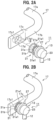
- FIGS. 2A and 2B are perspective views each illustrating a joint structure of a stabilizer link according to this embodiment of the present invention.
- FIG. 3 is a side view illustrating the joint structure of the stabilizer link according to this embodiment of the present invention.
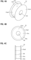
- FIG. 4A is a perspective view of an elastic member 31 that plays an important role in the present invention.
- FIG. 4B is a front view of the elastic member 31.
- FIG. 4C is a side view of the elastic member 31.
- the arm portion 17b of the stabilizer 17 has a flattened attachment portion 17c formed by press working.
- the attachment portion 17c has a through hole 17d shaped to receive a circular cylinder to be fitted therein.
- the through hole 17d is directed to a direction orthogonal to the longitudinal direction of the arm portion 17b.
- An elastic member 31 provided on the stud portion 21a of the ball stud 21 is attached to the through hole 17d of the attachment portion 17c.
- a material to form the elastic member 31 is not limited, it is preferable that a rubber elastic resin material such as natural rubber, epoxidized natural rubber, isoprene rubber, butadiene rubber, butadiene-isoprene rubber, styrene-butadiene rubber, chloroprene rubber, acrylonitrile-butadiene rubber (NBR), hydrogenated nitrile butadiene rubber, chlorinated polyethylene rubber, butyl rubber, acrylic rubber, ethylene-vinyl acetate-acrylic acid ester copolymer rubber, and silicone rubber is used.
- a rubber elastic resin material such as natural rubber, epoxidized natural rubber, isoprene rubber, butadiene rubber, butadiene-isoprene rubber, styrene-butadiene rubber, chloroprene rubber, acrylonitrile-butadiene rubber (NBR), hydrogenated nitrile butadiene rubber, chlorinated polyethylene rubber, butyl
- a body portion 31a of the elastic member 31 has a circular cylindrical central portion, and a penetration hole 33 extends through the central portion; the stud portion 21a of the ball stud 21 is inserted into the penetration hole 33.
- the inside diameter of the penetration hole 33 formed in the body portion 31a of the elastic member 31 is substantially equal to or slightly larger than the outside diameter of the stud portion 21a.
- the body portion 31a of the elastic member 31 serves to firmly bond the stud portion 21a of the ball stud 21 to the elastic member 31.
- This bonding function is achieved by vulcanized bonding of the inner wall of the penetration hole 33 formed in the body portion 31a and the stud portion 21a of the ball stud 21.
- the vulcanized bonding is carried out by applying an appropriate amount of adhesive to both of or at least one of the inner wall of the penetration hole 33 and the outer wall of the stud portion 21a so that an appropriate thickness of the adhesive layer is interposed between the inner wall of the penetration hole 33 and the outer wall of the stud portion 21a.
- a flange-side end face 31a3 that is located on the side opposite to the flange portion 21a1 may be vulcanized bonded to the circular disc-shaped flange portion 21a1 provided on the stud portion 21a to enhance the bonding function of the body portion 31a.
- This vulcanized bonding is also carried out by applying an appropriate amount of adhesive to both of or at least one of the flange-side end face 31a3 and the flange portion 21a1 so that an appropriate thickness of the adhesive layer is interposed between the flange-side end face 31a3 and the flange portion 21a1.
- the body portion 31a of the elastic member 31 has a holding function to tightly hold the outer wall of the body portion 31a against the inner wall of the through hole 17d with the elastic member 31 attached to the through hole 17d of the attachment portion 17c.
- This holding function is achieved by the size relationship in which the outside diameter of the body portion 31a of the elastic member 31 is substantially equal to or slightly smaller than the inside diameter of the through hole 17d of the attachment portion 17d.
- the body portion 31a of the elastic member 31 is interposed between the stabilizer link 11 and the stabilizer 17 to perform a vibration isolating function to prevent transmission of vibration between the stabilizer link 11 and the stabilizer 17.
- This vibration isolating function is achieved by a vibration isolating characteristic according to the spring constant previously set for the elastic member 31.
- the elastic member 31 has tab portions 31b having an anti-dropping (stopper) function to prevent the stabilizer link 11 from dropping from the attachment portion 17c of the arm portion 17b of the stabilizer 17.
- the tab portion 31b of the elastic member 31 is annularly and integrally formed on each peripheral edge portion 31a2 of a pair of donut-shaped end faces 31a1 of the body portion 31a (see FIGS. 4A and 4B ) to jut out radially outward.
- the tab portions 31b of the elastic member 31 are configured such that when the elastic member 31 is attached to the through hole 17d of the attachment portion 17c, circumferential edge portions 17d1 of the through hole 17d (see FIG. 2A ) are covered by the tab portions 31b.
- the elastic member 31 provided on the stud portion 21a of the ball stud 21 is press-fitted into the through hole 17d of the attachment portion 17c along the axial direction 18 of the stud portion 21a (see FIG. 2A ).
- a jig (not shown) may be used to apply a force opposite to that applied upon attachment (press-fitting) of the stud portion 21a of the ball stud 21; this force is applied to the stud portion 21a along the axial direction 18 of the stud portion 21a (see FIG. 2A ), while the attachment portion 17c of the arm portion 17b of the stabilizer 17 is fixed.
- the slip out load of the vulcanized bonding portion (between the inner wall of the penetration hole 33 formed in the body portion 31a and the stud portion 21a of the ball stud 21) is greater than the slip out load of the press-fitted portion (between the inner wall of the through hole 17d of the attachment portion 17c and the outer wall of the body portion 31a). For this reason, the elastic member 31 provided on the stud portion 21a can be removed from the through hole 17d of the attachment portion 17c without fail by the above-described procedures for removing the stabilizer link 11.
- vibration and noise can be suppressed, so that the ride comfort of the vehicle and the quietness in the passenger compartment can be retained satisfactorily.
- the stabilizer link 11 can be removed easily and reliably from the attachment portion 17c, for example, when the replacement of the stabilizer link 11 is necessary, the workload of the vehicle user can be greatly reduced as compared with the configuration in which an assembly of the stabilizer 17 and the stabilizer link 11 is replaced with another assembly when the replacement of the stabilizer link 11 is necessary.
- a tubular member for supporting the elastic member 31 is not required; this leads to reduced weight and cost reduction of the stabilizer link 11 as one component.
- an auxiliary effect can be expected in that precise and detailed managements are not required for the size of the attachment portion 17c, the smoothness around the through opening 17d formed in the attachment portion 17c, the thickness of the coating film, and the like.
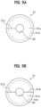
- FIGS. 5A and 5B are explanatory views (front views) each illustrating a modification of the elastic member 31.
- a slit 31c is formed in an axially radial direction of the elastic member 31. Accordingly, adhesive can be applied easily to the inner wall of the penetration hole 33 of the body portion 31a by expanding the elastic member 31 at the slit 31c.
- the elastic member 31 may be divided into two equal halves by slits formed along a center line 31d extending in an axially radial direction of the elastic member 31.
- FIGS. 6A to 6F are explanatory views (side views) according to modifications of the tab portion 31b provided on the elastic member 31.
- FIGS. 6A to 6F for convenience of explanation, the through hole 17d of the attachment portion 17c and the tab portion 31b of the elastic member 31 are shown such that the center line of the through hole 17d and the center line of the tab portion 31b are shifted in the axially radial direction (although these centerlines intrinsically coincide with each other in the actual joint structure of the stabilizer link 11).
- inner tab end portions 31b1 of the tab portions 31b are formed to rise along the side walls 17c1 of the attachment portion 17c; the inner tab end portions 31b1 face to the side walls 17c1 of the attachment portion 17c that form surfaces continuous with the circumferential edge portions 17d1 of the through hole 17d.
- inner tab end portions 31b1 of the tab portions 31b are formed to slant toward the side walls 17c1 of the attachment portion 17c; the inner tab end portions 31b1 face to the side walls 17c1 of the attachment portion 17c that form surfaces continuous with the circumferential edge portions 17d1 of the through hole 17d.
- a modification of the stud portion 21a of the ball stud 21 will be described.
- a surface processing such as sandblasting has been carried out to roughen the surface roughness at the outer circumferential wall (adhesive surface) around the axis of the stud portion 21a for the purpose of improvement in adhesion using vulcanized bonding and adhesive.
- another surface treatment such as knurling may be carried out to the outer circumferential wall (adhesive surface) of the stud portion 21a of the ball stud 21.
- a stabilizer link 11 configured to connect a suspension member 15 and a stabilizer 17 that are provided in a vehicle is joined to the stabilizer 17, wherein the stabilizer link 11 comprises a support bar 12 and a ball joint 13 provided on each end of the support bar 12.
- the ball joint comprises a ball stud 21 having a ball portion 21b and a stud portion 21a, and a housing 23 configured to support the ball portion 21b of the ball stud 21 so as to allow a rotation of the ball portion 21b.
- the stabilizer 17 is constituted by a rod-like member made of metal.
- the stabilizer 17 has two end portions, each of which includes an attachment portion 17c for joining the stabilizer link 11.
- Each of the attachment portions 17c has a through hole 17d, through which an elastic member 31 provided at the stud portion 21a of the ball stud 21 is attached to the attachment portion 17c.
- the elastic member 31 comprises a body portion 31a shaped like a circular cylinder, and a tab portion 31b provided on each of peripheral edge portions 31a2 of a pair of donut-shaped end faces 31a1 of the body portion 31a.
- the stud portion 21a of the ball stud 21 is joined to the attachment portion 17c through the elastic member 31 in such a manner that while the elastic member 31 is attached to the through hole 17d, the body portion 31a abuts on an inner circumferential wall portion of the through hole 17d and the tab portions 31b are located to cover circumferential edge portions 17d1 of the through hole 17d.
- the joint structure of the stabilizer link according to the embodiment is configured such that the elastic member 31 further comprises a penetration hole 33 through which the stud portion 21a of the ball stud 21 is inserted into the elastic member, and the elastic member 31 is provided on the stud portion 21a by bonding the stud portion 21a to the penetration hole 33 with the stud portion 21a attached to the penetration hole 33.
- the elastic member 31 is provided on the stud portion 21a by bonding the stud portion 21a to the penetration hole 33 with the stud portion 21a attached to the penetration hole 33, the elastic member 31 can be fixed reliably to the stud portion 21a.
- the joint structure of the stabilizer link according to the embodiment is configured such that the stud portion 21a of the ball stud 21 comprises a flange portion 21a1 shaped like a circular disc, and the elastic member 31 is bonded to the flange portion 21a1 with the stud portion 21a attached to the penetration hole 33.
- the inner tab end portions 31b1 of the tab portions 31b shown in FIGS. 6A to 6F have the same shape (rising shape or slanting shape) for one elastic member 31; however, the present invention is not limited to this specific example.
- the tab portions 31b of one elastic member 31 may have different shaped inner tab end portions 31b1 from each other.
- tab portions 31b provided on the elastic member 31 according to the present invention as shown in FIGS. 6A to 6F have been exemplified as examples to embody the present invention; however, the present invention is not limited to these examples.
- the tab portions 31b provided on the elastic member 31 according to the present invention may be configured to have any configurations as long as the anti-dropping (stopper) function to prevent the stabilizer link 11 from dropping from the attachment portion 17c can be performed.
Landscapes
- Engineering & Computer Science (AREA)
- Mechanical Engineering (AREA)
- General Engineering & Computer Science (AREA)
- Vehicle Body Suspensions (AREA)
- Pivots And Pivotal Connections (AREA)
Claims (1)
- Verbindungsstruktur mit einer Stabilisatorverbindung (11), bei der die Stabilisatorverbindung, die dazu konfiguriert ist, ein in einem Fahrzeug bereitgestelltes Aufhängungselement (15) und einen Stabilisator (17) zu verbinden, an den Stabilisator angeschlossen ist,wobei die Stabilisatorverbindung (11) eine Stützstange (12) und ein an jedem Ende der Stützstange bereitgestelltes Kugelgelenk (13) umfasst,wobei jedes Kugelgelenk (13) einen Kugelzapfen (21) mit einem Kugelabschnitt (21b) und einem Zapfenabschnitt (21a) und ein Gehäuse (23) umfasst, das so konfiguriert ist, dass es den Kugelabschnitt (21b) des Kugelzapfens stützt, um eine Drehung des Kugelabschnitts zu ermöglichen,wobei der Stabilisator (17) aus einem stabähnlichen Element aus Metall besteht, und der Stabilisator zwei Endabschnitte aufweist, von denen jeder einen Befestigungsabschnitt (17c) zum Anschließen der Stabilisatorverbindung (11) beinhaltet, undwobei jeder der Befestigungsabschnitte (17c) ein Durchgangsloch (17d) aufweist, ein elastisches Element (31), das an dem Zapfenabschnitt (21a) des Kugelzapfens eines Kugelgelenks (13) an einem Ende der Stabilisatorverbindung (11) bereitgestellt ist, geeignet ist, an dem Befestigungsabschnitt (17c) durch das Durchgangsloch (17d) befestigt zu werden,das elastische Element (31) einen Körperabschnitt (31a), der wie ein Kreiszylinder geformt ist, und einen Laschenabschnitt (31b) umfasst, der an jedem von einem Paar außenseitiger Umfangskantenabschnitte (31a2) des Körperabschnitts bereitgestellt ist,der Zapfenabschnitt (21a) des Kugelzapfens (21) geeignet ist, über das elastische Element (31) an den Befestigungsabschnitt (17c) derart angeschlossen zu werden, dass, während das elastische Element an dem Durchgangsloch (17d) befestigt ist, der Körperabschnitt (31a) an einem inneren Abschnitt der Umfangswand des Durchgangslochs anliegt und die Laschenabschnitte (31b) so angeordnet sind, dass sie ein Paar äußerer Umfangsabschnitte des Durchgangslochs abdecken,das elastische Element (31) weiter ein Durchdringungsloch (33) umfasst, durch das der Zapfenabschnitt (21a) des Kugelzapfens (21) in das elastische Element (31) eingeführt wird,das elastische Element (31) an dem Zapfenabschnitt (21a) bereitgestellt wird, indem der Zapfenabschnitt an das Durchdringungsloch (33) geklebt wird, wobei der Zapfenabschnitt an dem Durchdringungsloch befestigt wird,der Zapfenabschnitt (21a) des Kugelzapfens (21) einen Flanschabschnitt (21a1) umfasst, der wie eine kreisförmige Scheibe geformt ist, unddas elastische Element (31) an den Flanschabschnitt (21a1) geklebt ist, wobei der Zapfenabschnitt (21a) des Kugelzapfens (21) an dem Durchdringungsloch (33) befestigt ist.
Applications Claiming Priority (2)
| Application Number | Priority Date | Filing Date | Title |
|---|---|---|---|
| JP2017110408A JP6904790B2 (ja) | 2017-06-02 | 2017-06-02 | スタビリンクの接合構造 |
| PCT/JP2018/018010 WO2018221147A1 (ja) | 2017-06-02 | 2018-05-09 | スタビリンクの接合構造 |
Publications (3)
| Publication Number | Publication Date |
|---|---|
| EP3632717A1 EP3632717A1 (de) | 2020-04-08 |
| EP3632717A4 EP3632717A4 (de) | 2021-03-03 |
| EP3632717B1 true EP3632717B1 (de) | 2023-11-15 |
Family
ID=64455889
Family Applications (1)
| Application Number | Title | Priority Date | Filing Date |
|---|---|---|---|
| EP18810566.2A Active EP3632717B1 (de) | 2017-06-02 | 2018-05-09 | Verbindungsstruktur einer stabilisatorverbindung |
Country Status (6)
| Country | Link |
|---|---|
| US (1) | US20200171910A1 (de) |
| EP (1) | EP3632717B1 (de) |
| JP (1) | JP6904790B2 (de) |
| KR (1) | KR102238853B1 (de) |
| CN (1) | CN110709264B (de) |
| WO (1) | WO2018221147A1 (de) |
Families Citing this family (1)
| Publication number | Priority date | Publication date | Assignee | Title |
|---|---|---|---|---|
| JP7162573B2 (ja) * | 2019-07-02 | 2022-10-28 | 日本発條株式会社 | スタビライザ |
Family Cites Families (17)
| Publication number | Priority date | Publication date | Assignee | Title |
|---|---|---|---|---|
| US4067525A (en) | 1976-11-18 | 1978-01-10 | Bushings, Inc. | Resilient mounting |
| JPS5854246Y2 (ja) * | 1980-02-19 | 1983-12-10 | 中央発條株式会社 | 車輪懸架装置用中空スタビライザ |
| JPH05141462A (ja) * | 1991-11-20 | 1993-06-08 | Bridgestone Corp | 筒形防振ゴム |
| JP2575970Y2 (ja) * | 1993-02-25 | 1998-07-02 | 丸五ゴム工業株式会社 | スタビライザの軸受装置 |
| JPH0713514U (ja) * | 1993-08-20 | 1995-03-07 | 日産ディーゼル工業株式会社 | ローリングスタビライザ装置 |
| JP3701702B2 (ja) * | 1994-09-30 | 2005-10-05 | 中央発條株式会社 | 自動車用スタビライザ装置 |
| JPH11139129A (ja) * | 1997-09-08 | 1999-05-25 | Toyoda Gosei Co Ltd | サスペンション用リンク機構 |
| JP4169928B2 (ja) * | 2000-12-04 | 2008-10-22 | 日産ディーゼル工業株式会社 | トラニオン式サスペンションのアクスル傾角の変更方法 |
| JP3848556B2 (ja) * | 2001-10-18 | 2006-11-22 | 日本発条株式会社 | 中空スタビライザ |
| JP4961775B2 (ja) * | 2006-03-07 | 2012-06-27 | 住友電気工業株式会社 | 鉄道車両用のリンクおよびその製造方法 |
| JP4983106B2 (ja) * | 2006-06-15 | 2012-07-25 | トヨタ自動車株式会社 | スタビライザ装置 |
| KR20080023429A (ko) * | 2006-09-11 | 2008-03-14 | 현대자동차주식회사 | 스테빌라이저 엔드부의 마운팅 |
| US20080163453A1 (en) * | 2007-01-09 | 2008-07-10 | Jerry Joseph | Bushing for suspension system |
| US7914023B2 (en) | 2009-03-13 | 2011-03-29 | GM Global Technology Operations LLC | Parallelogram-style steering mechanism having a relay rod bushing |
| JP5847216B2 (ja) * | 2014-02-18 | 2016-01-20 | 日本発條株式会社 | リンクアーム部材の製造方法 |
| JP5926763B2 (ja) * | 2014-04-24 | 2016-05-25 | 日本発條株式会社 | ゴムブッシュ付きスタビライザーバーの製造方法 |
| JP5923154B2 (ja) * | 2014-10-28 | 2016-05-24 | 日本発條株式会社 | リンクアーム部材 |
-
2017
- 2017-06-02 JP JP2017110408A patent/JP6904790B2/ja active Active
-
2018
- 2018-05-09 US US16/617,761 patent/US20200171910A1/en not_active Abandoned
- 2018-05-09 CN CN201880035056.7A patent/CN110709264B/zh active Active
- 2018-05-09 KR KR1020197031990A patent/KR102238853B1/ko active IP Right Grant
- 2018-05-09 EP EP18810566.2A patent/EP3632717B1/de active Active
- 2018-05-09 WO PCT/JP2018/018010 patent/WO2018221147A1/ja unknown
Also Published As
| Publication number | Publication date |
|---|---|
| WO2018221147A1 (ja) | 2018-12-06 |
| CN110709264A (zh) | 2020-01-17 |
| KR102238853B1 (ko) | 2021-04-09 |
| JP2018203033A (ja) | 2018-12-27 |
| US20200171910A1 (en) | 2020-06-04 |
| CN110709264B (zh) | 2023-02-17 |
| EP3632717A4 (de) | 2021-03-03 |
| EP3632717A1 (de) | 2020-04-08 |
| JP6904790B2 (ja) | 2021-07-21 |
| KR20190127958A (ko) | 2019-11-13 |
Similar Documents
| Publication | Publication Date | Title |
|---|---|---|
| KR101607247B1 (ko) | 차량의 너클 | |
| WO2014192081A1 (ja) | 車両用リンク部品およびその製造方法 | |
| US20060232036A1 (en) | Steering damper to drag link attachment clamp and method | |
| WO2015136346A1 (en) | Strut-type suspension device | |
| EP3632717B1 (de) | Verbindungsstruktur einer stabilisatorverbindung | |
| JP2003294084A (ja) | 防振ブッシュ | |
| KR101819143B1 (ko) | 베어링이 구비된 일체형 더스트 커버 | |
| KR20190038916A (ko) | 스태빌라이저의 제조 방법, 및 스태빌라이저 링크의 접합 구조 | |
| WO2015119158A1 (ja) | ショックアブソーバ | |
| US9175730B2 (en) | Mounting assembly | |
| JP2011162093A (ja) | ショックアブソーバの取付構造 | |
| JPH08219210A (ja) | 防振支持体 | |
| KR20210062133A (ko) | 차량용 스테빌라이저바의 부시 장치 | |
| KR102261282B1 (ko) | 필로우 볼 조인트 어셈블리 | |
| US9434228B1 (en) | Vehicle component mounting apparatus, and methods of use and manufacture thereof | |
| JP4511422B2 (ja) | ブッシュ組立体 | |
| JP6546715B2 (ja) | ストラットマウント | |
| JP6975030B2 (ja) | 防振装置及び防振構造 | |
| KR102552072B1 (ko) | 내측고정방식 마운팅 부시 유닛 및 서브프레임 | |
| JPH11257410A (ja) | ストラットの車輪側取付部構造 | |
| JP2016161102A (ja) | ストラット式サスペンション装置 | |
| JP2023012218A (ja) | 軸継手装置 | |
| KR101450324B1 (ko) | 자동차 조향장치의 랙바 지지장치 | |
| JPH11182601A (ja) | 防振装置 | |
| JPS6319439A (ja) | 懸架装置の防振支持構体 |
Legal Events
| Date | Code | Title | Description |
|---|---|---|---|
| STAA | Information on the status of an ep patent application or granted ep patent |
Free format text: STATUS: THE INTERNATIONAL PUBLICATION HAS BEEN MADE |
|
| PUAI | Public reference made under article 153(3) epc to a published international application that has entered the european phase |
Free format text: ORIGINAL CODE: 0009012 |
|
| STAA | Information on the status of an ep patent application or granted ep patent |
Free format text: STATUS: REQUEST FOR EXAMINATION WAS MADE |
|
| 17P | Request for examination filed |
Effective date: 20191219 |
|
| AK | Designated contracting states |
Kind code of ref document: A1 Designated state(s): AL AT BE BG CH CY CZ DE DK EE ES FI FR GB GR HR HU IE IS IT LI LT LU LV MC MK MT NL NO PL PT RO RS SE SI SK SM TR |
|
| AX | Request for extension of the european patent |
Extension state: BA ME |
|
| DAV | Request for validation of the european patent (deleted) | ||
| DAX | Request for extension of the european patent (deleted) | ||
| A4 | Supplementary search report drawn up and despatched |
Effective date: 20210128 |
|
| RIC1 | Information provided on ipc code assigned before grant |
Ipc: B60G 21/055 20060101AFI20210122BHEP Ipc: F16C 11/06 20060101ALI20210122BHEP |
|
| GRAP | Despatch of communication of intention to grant a patent |
Free format text: ORIGINAL CODE: EPIDOSNIGR1 |
|
| STAA | Information on the status of an ep patent application or granted ep patent |
Free format text: STATUS: GRANT OF PATENT IS INTENDED |
|
| INTG | Intention to grant announced |
Effective date: 20221124 |
|
| GRAJ | Information related to disapproval of communication of intention to grant by the applicant or resumption of examination proceedings by the epo deleted |
Free format text: ORIGINAL CODE: EPIDOSDIGR1 |
|
| STAA | Information on the status of an ep patent application or granted ep patent |
Free format text: STATUS: REQUEST FOR EXAMINATION WAS MADE |
|
| INTC | Intention to grant announced (deleted) | ||
| GRAP | Despatch of communication of intention to grant a patent |
Free format text: ORIGINAL CODE: EPIDOSNIGR1 |
|
| STAA | Information on the status of an ep patent application or granted ep patent |
Free format text: STATUS: GRANT OF PATENT IS INTENDED |
|
| INTG | Intention to grant announced |
Effective date: 20230531 |
|
| GRAS | Grant fee paid |
Free format text: ORIGINAL CODE: EPIDOSNIGR3 |
|
| GRAA | (expected) grant |
Free format text: ORIGINAL CODE: 0009210 |
|
| STAA | Information on the status of an ep patent application or granted ep patent |
Free format text: STATUS: THE PATENT HAS BEEN GRANTED |
|
| AK | Designated contracting states |
Kind code of ref document: B1 Designated state(s): AL AT BE BG CH CY CZ DE DK EE ES FI FR GB GR HR HU IE IS IT LI LT LU LV MC MK MT NL NO PL PT RO RS SE SI SK SM TR |
|
| REG | Reference to a national code |
Ref country code: CH Ref legal event code: EP Ref country code: GB Ref legal event code: FG4D |
|
| REG | Reference to a national code |
Ref country code: DE Ref legal event code: R096 Ref document number: 602018061187 Country of ref document: DE |
|
| REG | Reference to a national code |
Ref country code: IE Ref legal event code: FG4D |
|
| P01 | Opt-out of the competence of the unified patent court (upc) registered |
Effective date: 20231108 |
|
| REG | Reference to a national code |
Ref country code: LT Ref legal event code: MG9D |
|
| REG | Reference to a national code |
Ref country code: NL Ref legal event code: MP Effective date: 20231115 |
|
| PG25 | Lapsed in a contracting state [announced via postgrant information from national office to epo] |
Ref country code: GR Free format text: LAPSE BECAUSE OF FAILURE TO SUBMIT A TRANSLATION OF THE DESCRIPTION OR TO PAY THE FEE WITHIN THE PRESCRIBED TIME-LIMIT Effective date: 20240216 |
|
| PG25 | Lapsed in a contracting state [announced via postgrant information from national office to epo] |
Ref country code: IS Free format text: LAPSE BECAUSE OF FAILURE TO SUBMIT A TRANSLATION OF THE DESCRIPTION OR TO PAY THE FEE WITHIN THE PRESCRIBED TIME-LIMIT Effective date: 20240315 |
|
| PG25 | Lapsed in a contracting state [announced via postgrant information from national office to epo] |
Ref country code: LT Free format text: LAPSE BECAUSE OF FAILURE TO SUBMIT A TRANSLATION OF THE DESCRIPTION OR TO PAY THE FEE WITHIN THE PRESCRIBED TIME-LIMIT Effective date: 20231115 |
|
| REG | Reference to a national code |
Ref country code: AT Ref legal event code: MK05 Ref document number: 1631457 Country of ref document: AT Kind code of ref document: T Effective date: 20231115 |
|
| PG25 | Lapsed in a contracting state [announced via postgrant information from national office to epo] |
Ref country code: NL Free format text: LAPSE BECAUSE OF FAILURE TO SUBMIT A TRANSLATION OF THE DESCRIPTION OR TO PAY THE FEE WITHIN THE PRESCRIBED TIME-LIMIT Effective date: 20231115 |
|
| PG25 | Lapsed in a contracting state [announced via postgrant information from national office to epo] |
Ref country code: AT Free format text: LAPSE BECAUSE OF FAILURE TO SUBMIT A TRANSLATION OF THE DESCRIPTION OR TO PAY THE FEE WITHIN THE PRESCRIBED TIME-LIMIT Effective date: 20231115 |
|
| PG25 | Lapsed in a contracting state [announced via postgrant information from national office to epo] |
Ref country code: ES Free format text: LAPSE BECAUSE OF FAILURE TO SUBMIT A TRANSLATION OF THE DESCRIPTION OR TO PAY THE FEE WITHIN THE PRESCRIBED TIME-LIMIT Effective date: 20231115 |
|
| PG25 | Lapsed in a contracting state [announced via postgrant information from national office to epo] |
Ref country code: NL Free format text: LAPSE BECAUSE OF FAILURE TO SUBMIT A TRANSLATION OF THE DESCRIPTION OR TO PAY THE FEE WITHIN THE PRESCRIBED TIME-LIMIT Effective date: 20231115 Ref country code: LT Free format text: LAPSE BECAUSE OF FAILURE TO SUBMIT A TRANSLATION OF THE DESCRIPTION OR TO PAY THE FEE WITHIN THE PRESCRIBED TIME-LIMIT Effective date: 20231115 Ref country code: IS Free format text: LAPSE BECAUSE OF FAILURE TO SUBMIT A TRANSLATION OF THE DESCRIPTION OR TO PAY THE FEE WITHIN THE PRESCRIBED TIME-LIMIT Effective date: 20240315 Ref country code: GR Free format text: LAPSE BECAUSE OF FAILURE TO SUBMIT A TRANSLATION OF THE DESCRIPTION OR TO PAY THE FEE WITHIN THE PRESCRIBED TIME-LIMIT Effective date: 20240216 Ref country code: ES Free format text: LAPSE BECAUSE OF FAILURE TO SUBMIT A TRANSLATION OF THE DESCRIPTION OR TO PAY THE FEE WITHIN THE PRESCRIBED TIME-LIMIT Effective date: 20231115 Ref country code: BG Free format text: LAPSE BECAUSE OF FAILURE TO SUBMIT A TRANSLATION OF THE DESCRIPTION OR TO PAY THE FEE WITHIN THE PRESCRIBED TIME-LIMIT Effective date: 20240215 Ref country code: AT Free format text: LAPSE BECAUSE OF FAILURE TO SUBMIT A TRANSLATION OF THE DESCRIPTION OR TO PAY THE FEE WITHIN THE PRESCRIBED TIME-LIMIT Effective date: 20231115 Ref country code: PT Free format text: LAPSE BECAUSE OF FAILURE TO SUBMIT A TRANSLATION OF THE DESCRIPTION OR TO PAY THE FEE WITHIN THE PRESCRIBED TIME-LIMIT Effective date: 20240315 |
|
| PG25 | Lapsed in a contracting state [announced via postgrant information from national office to epo] |
Ref country code: SE Free format text: LAPSE BECAUSE OF FAILURE TO SUBMIT A TRANSLATION OF THE DESCRIPTION OR TO PAY THE FEE WITHIN THE PRESCRIBED TIME-LIMIT Effective date: 20231115 Ref country code: RS Free format text: LAPSE BECAUSE OF FAILURE TO SUBMIT A TRANSLATION OF THE DESCRIPTION OR TO PAY THE FEE WITHIN THE PRESCRIBED TIME-LIMIT Effective date: 20231115 Ref country code: PL Free format text: LAPSE BECAUSE OF FAILURE TO SUBMIT A TRANSLATION OF THE DESCRIPTION OR TO PAY THE FEE WITHIN THE PRESCRIBED TIME-LIMIT Effective date: 20231115 Ref country code: NO Free format text: LAPSE BECAUSE OF FAILURE TO SUBMIT A TRANSLATION OF THE DESCRIPTION OR TO PAY THE FEE WITHIN THE PRESCRIBED TIME-LIMIT Effective date: 20240215 Ref country code: LV Free format text: LAPSE BECAUSE OF FAILURE TO SUBMIT A TRANSLATION OF THE DESCRIPTION OR TO PAY THE FEE WITHIN THE PRESCRIBED TIME-LIMIT Effective date: 20231115 Ref country code: HR Free format text: LAPSE BECAUSE OF FAILURE TO SUBMIT A TRANSLATION OF THE DESCRIPTION OR TO PAY THE FEE WITHIN THE PRESCRIBED TIME-LIMIT Effective date: 20231115 |
|
| PGFP | Annual fee paid to national office [announced via postgrant information from national office to epo] |
Ref country code: GB Payment date: 20240521 Year of fee payment: 7 |
|
| PGFP | Annual fee paid to national office [announced via postgrant information from national office to epo] |
Ref country code: DE Payment date: 20240520 Year of fee payment: 7 |
|
| PG25 | Lapsed in a contracting state [announced via postgrant information from national office to epo] |
Ref country code: DK Free format text: LAPSE BECAUSE OF FAILURE TO SUBMIT A TRANSLATION OF THE DESCRIPTION OR TO PAY THE FEE WITHIN THE PRESCRIBED TIME-LIMIT Effective date: 20231115 |
|
| PG25 | Lapsed in a contracting state [announced via postgrant information from national office to epo] |
Ref country code: CZ Free format text: LAPSE BECAUSE OF FAILURE TO SUBMIT A TRANSLATION OF THE DESCRIPTION OR TO PAY THE FEE WITHIN THE PRESCRIBED TIME-LIMIT Effective date: 20231115 |
|
| PG25 | Lapsed in a contracting state [announced via postgrant information from national office to epo] |
Ref country code: SK Free format text: LAPSE BECAUSE OF FAILURE TO SUBMIT A TRANSLATION OF THE DESCRIPTION OR TO PAY THE FEE WITHIN THE PRESCRIBED TIME-LIMIT Effective date: 20231115 |
|
| PG25 | Lapsed in a contracting state [announced via postgrant information from national office to epo] |
Ref country code: SM Free format text: LAPSE BECAUSE OF FAILURE TO SUBMIT A TRANSLATION OF THE DESCRIPTION OR TO PAY THE FEE WITHIN THE PRESCRIBED TIME-LIMIT Effective date: 20231115 Ref country code: SK Free format text: LAPSE BECAUSE OF FAILURE TO SUBMIT A TRANSLATION OF THE DESCRIPTION OR TO PAY THE FEE WITHIN THE PRESCRIBED TIME-LIMIT Effective date: 20231115 Ref country code: RO Free format text: LAPSE BECAUSE OF FAILURE TO SUBMIT A TRANSLATION OF THE DESCRIPTION OR TO PAY THE FEE WITHIN THE PRESCRIBED TIME-LIMIT Effective date: 20231115 Ref country code: IT Free format text: LAPSE BECAUSE OF FAILURE TO SUBMIT A TRANSLATION OF THE DESCRIPTION OR TO PAY THE FEE WITHIN THE PRESCRIBED TIME-LIMIT Effective date: 20231115 Ref country code: EE Free format text: LAPSE BECAUSE OF FAILURE TO SUBMIT A TRANSLATION OF THE DESCRIPTION OR TO PAY THE FEE WITHIN THE PRESCRIBED TIME-LIMIT Effective date: 20231115 Ref country code: DK Free format text: LAPSE BECAUSE OF FAILURE TO SUBMIT A TRANSLATION OF THE DESCRIPTION OR TO PAY THE FEE WITHIN THE PRESCRIBED TIME-LIMIT Effective date: 20231115 Ref country code: CZ Free format text: LAPSE BECAUSE OF FAILURE TO SUBMIT A TRANSLATION OF THE DESCRIPTION OR TO PAY THE FEE WITHIN THE PRESCRIBED TIME-LIMIT Effective date: 20231115 |
|
| PGFP | Annual fee paid to national office [announced via postgrant information from national office to epo] |
Ref country code: FR Payment date: 20240517 Year of fee payment: 7 |
|
| REG | Reference to a national code |
Ref country code: DE Ref legal event code: R097 Ref document number: 602018061187 Country of ref document: DE |
|
| PLBE | No opposition filed within time limit |
Free format text: ORIGINAL CODE: 0009261 |
|
| STAA | Information on the status of an ep patent application or granted ep patent |
Free format text: STATUS: NO OPPOSITION FILED WITHIN TIME LIMIT |