WO2018221147A1 - スタビリンクの接合構造 - Google Patents
スタビリンクの接合構造 Download PDFInfo
- Publication number
- WO2018221147A1 WO2018221147A1 PCT/JP2018/018010 JP2018018010W WO2018221147A1 WO 2018221147 A1 WO2018221147 A1 WO 2018221147A1 JP 2018018010 W JP2018018010 W JP 2018018010W WO 2018221147 A1 WO2018221147 A1 WO 2018221147A1
- Authority
- WO
- WIPO (PCT)
- Prior art keywords
- stud
- elastic member
- hole
- stabilizer
- ball
- Prior art date
Links
- 239000003381 stabilizer Substances 0.000 title claims abstract description 113
- 230000002093 peripheral effect Effects 0.000 claims abstract description 26
- 238000005304 joining Methods 0.000 claims description 22
- 239000000725 suspension Substances 0.000 claims description 10
- 239000002184 metal Substances 0.000 claims description 6
- 210000005069 ears Anatomy 0.000 claims description 2
- 230000004048 modification Effects 0.000 description 20
- 238000012986 modification Methods 0.000 description 20
- 239000000853 adhesive Substances 0.000 description 6
- 210000003027 ear inner Anatomy 0.000 description 6
- 229920002857 polybutadiene Polymers 0.000 description 5
- 239000011347 resin Substances 0.000 description 5
- 229920005989 resin Polymers 0.000 description 5
- 239000005062 Polybutadiene Substances 0.000 description 4
- 230000001070 adhesive effect Effects 0.000 description 4
- 239000011248 coating agent Substances 0.000 description 4
- 238000000576 coating method Methods 0.000 description 4
- 229920001971 elastomer Polymers 0.000 description 4
- 239000005060 rubber Substances 0.000 description 4
- 230000035939 shock Effects 0.000 description 4
- 238000004073 vulcanization Methods 0.000 description 4
- 229920002430 Fibre-reinforced plastic Polymers 0.000 description 3
- 239000006096 absorbing agent Substances 0.000 description 3
- 239000012790 adhesive layer Substances 0.000 description 3
- 239000004918 carbon fiber reinforced polymer Substances 0.000 description 3
- 239000000428 dust Substances 0.000 description 3
- 239000011151 fibre-reinforced plastic Substances 0.000 description 3
- 238000000034 method Methods 0.000 description 3
- KAKZBPTYRLMSJV-UHFFFAOYSA-N Butadiene Chemical compound C=CC=C KAKZBPTYRLMSJV-UHFFFAOYSA-N 0.000 description 2
- 244000043261 Hevea brasiliensis Species 0.000 description 2
- 229910000831 Steel Inorganic materials 0.000 description 2
- MTAZNLWOLGHBHU-UHFFFAOYSA-N butadiene-styrene rubber Chemical compound C=CC=C.C=CC1=CC=CC=C1 MTAZNLWOLGHBHU-UHFFFAOYSA-N 0.000 description 2
- 230000000694 effects Effects 0.000 description 2
- 229920003049 isoprene rubber Polymers 0.000 description 2
- 229920003052 natural elastomer Polymers 0.000 description 2
- 229920001194 natural rubber Polymers 0.000 description 2
- 238000003825 pressing Methods 0.000 description 2
- 230000002265 prevention Effects 0.000 description 2
- 230000008569 process Effects 0.000 description 2
- 239000010959 steel Substances 0.000 description 2
- 230000003746 surface roughness Effects 0.000 description 2
- NLHHRLWOUZZQLW-UHFFFAOYSA-N Acrylonitrile Chemical compound C=CC#N NLHHRLWOUZZQLW-UHFFFAOYSA-N 0.000 description 1
- VGGSQFUCUMXWEO-UHFFFAOYSA-N Ethene Chemical compound C=C VGGSQFUCUMXWEO-UHFFFAOYSA-N 0.000 description 1
- 239000005977 Ethylene Substances 0.000 description 1
- 229910000639 Spring steel Inorganic materials 0.000 description 1
- XTXRWKRVRITETP-UHFFFAOYSA-N Vinyl acetate Chemical compound CC(=O)OC=C XTXRWKRVRITETP-UHFFFAOYSA-N 0.000 description 1
- 229920000800 acrylic rubber Polymers 0.000 description 1
- 230000000712 assembly Effects 0.000 description 1
- 238000000429 assembly Methods 0.000 description 1
- 230000005540 biological transmission Effects 0.000 description 1
- 229920005549 butyl rubber Polymers 0.000 description 1
- 229920006235 chlorinated polyethylene elastomer Polymers 0.000 description 1
- 229920001577 copolymer Polymers 0.000 description 1
- 235000012489 doughnuts Nutrition 0.000 description 1
- 239000013013 elastic material Substances 0.000 description 1
- 230000006872 improvement Effects 0.000 description 1
- 239000000463 material Substances 0.000 description 1
- 150000002825 nitriles Chemical class 0.000 description 1
- 230000000149 penetrating effect Effects 0.000 description 1
- 229920001084 poly(chloroprene) Polymers 0.000 description 1
- 229920000058 polyacrylate Polymers 0.000 description 1
- 230000009467 reduction Effects 0.000 description 1
- 238000005096 rolling process Methods 0.000 description 1
- 238000007788 roughening Methods 0.000 description 1
- 230000009291 secondary effect Effects 0.000 description 1
- 229920002379 silicone rubber Polymers 0.000 description 1
- 239000004945 silicone rubber Substances 0.000 description 1
- 239000007787 solid Substances 0.000 description 1
- 239000013585 weight reducing agent Substances 0.000 description 1
- 238000003466 welding Methods 0.000 description 1
Images


Classifications
-
- B—PERFORMING OPERATIONS; TRANSPORTING
- B60—VEHICLES IN GENERAL
- B60G—VEHICLE SUSPENSION ARRANGEMENTS
- B60G21/00—Interconnection systems for two or more resiliently-suspended wheels, e.g. for stabilising a vehicle body with respect to acceleration, deceleration or centrifugal forces
- B60G21/02—Interconnection systems for two or more resiliently-suspended wheels, e.g. for stabilising a vehicle body with respect to acceleration, deceleration or centrifugal forces permanently interconnected
- B60G21/04—Interconnection systems for two or more resiliently-suspended wheels, e.g. for stabilising a vehicle body with respect to acceleration, deceleration or centrifugal forces permanently interconnected mechanically
- B60G21/05—Interconnection systems for two or more resiliently-suspended wheels, e.g. for stabilising a vehicle body with respect to acceleration, deceleration or centrifugal forces permanently interconnected mechanically between wheels on the same axle but on different sides of the vehicle, i.e. the left and right wheel suspensions being interconnected
- B60G21/055—Stabiliser bars
- B60G21/0551—Mounting means therefor
-
- B—PERFORMING OPERATIONS; TRANSPORTING
- B60—VEHICLES IN GENERAL
- B60G—VEHICLE SUSPENSION ARRANGEMENTS
- B60G21/00—Interconnection systems for two or more resiliently-suspended wheels, e.g. for stabilising a vehicle body with respect to acceleration, deceleration or centrifugal forces
- B60G21/02—Interconnection systems for two or more resiliently-suspended wheels, e.g. for stabilising a vehicle body with respect to acceleration, deceleration or centrifugal forces permanently interconnected
- B60G21/04—Interconnection systems for two or more resiliently-suspended wheels, e.g. for stabilising a vehicle body with respect to acceleration, deceleration or centrifugal forces permanently interconnected mechanically
- B60G21/05—Interconnection systems for two or more resiliently-suspended wheels, e.g. for stabilising a vehicle body with respect to acceleration, deceleration or centrifugal forces permanently interconnected mechanically between wheels on the same axle but on different sides of the vehicle, i.e. the left and right wheel suspensions being interconnected
- B60G21/055—Stabiliser bars
-
- F—MECHANICAL ENGINEERING; LIGHTING; HEATING; WEAPONS; BLASTING
- F16—ENGINEERING ELEMENTS AND UNITS; GENERAL MEASURES FOR PRODUCING AND MAINTAINING EFFECTIVE FUNCTIONING OF MACHINES OR INSTALLATIONS; THERMAL INSULATION IN GENERAL
- F16C—SHAFTS; FLEXIBLE SHAFTS; ELEMENTS OR CRANKSHAFT MECHANISMS; ROTARY BODIES OTHER THAN GEARING ELEMENTS; BEARINGS
- F16C11/00—Pivots; Pivotal connections
- F16C11/04—Pivotal connections
- F16C11/06—Ball-joints; Other joints having more than one degree of angular freedom, i.e. universal joints
- F16C11/08—Ball-joints; Other joints having more than one degree of angular freedom, i.e. universal joints with resilient bearings
- F16C11/083—Ball-joints; Other joints having more than one degree of angular freedom, i.e. universal joints with resilient bearings by means of parts of rubber or like materials
-
- B—PERFORMING OPERATIONS; TRANSPORTING
- B60—VEHICLES IN GENERAL
- B60G—VEHICLE SUSPENSION ARRANGEMENTS
- B60G2204/00—Indexing codes related to suspensions per se or to auxiliary parts
- B60G2204/10—Mounting of suspension elements
- B60G2204/12—Mounting of springs or dampers
- B60G2204/122—Mounting of torsion springs
- B60G2204/1224—End mounts of stabiliser on wheel suspension
-
- B—PERFORMING OPERATIONS; TRANSPORTING
- B60—VEHICLES IN GENERAL
- B60G—VEHICLE SUSPENSION ARRANGEMENTS
- B60G2204/00—Indexing codes related to suspensions per se or to auxiliary parts
- B60G2204/40—Auxiliary suspension parts; Adjustment of suspensions
- B60G2204/41—Elastic mounts, e.g. bushings
-
- B—PERFORMING OPERATIONS; TRANSPORTING
- B60—VEHICLES IN GENERAL
- B60G—VEHICLE SUSPENSION ARRANGEMENTS
- B60G2204/00—Indexing codes related to suspensions per se or to auxiliary parts
- B60G2204/40—Auxiliary suspension parts; Adjustment of suspensions
- B60G2204/416—Ball or spherical joints
-
- B—PERFORMING OPERATIONS; TRANSPORTING
- B60—VEHICLES IN GENERAL
- B60G—VEHICLE SUSPENSION ARRANGEMENTS
- B60G2204/00—Indexing codes related to suspensions per se or to auxiliary parts
- B60G2204/40—Auxiliary suspension parts; Adjustment of suspensions
- B60G2204/422—Links for mounting suspension elements
-
- B—PERFORMING OPERATIONS; TRANSPORTING
- B60—VEHICLES IN GENERAL
- B60G—VEHICLE SUSPENSION ARRANGEMENTS
- B60G2206/00—Indexing codes related to the manufacturing of suspensions: constructional features, the materials used, procedures or tools
- B60G2206/01—Constructional features of suspension elements, e.g. arms, dampers, springs
- B60G2206/40—Constructional features of dampers and/or springs
- B60G2206/42—Springs
- B60G2206/427—Stabiliser bars or tubes
-
- B—PERFORMING OPERATIONS; TRANSPORTING
- B60—VEHICLES IN GENERAL
- B60G—VEHICLE SUSPENSION ARRANGEMENTS
- B60G2206/00—Indexing codes related to the manufacturing of suspensions: constructional features, the materials used, procedures or tools
- B60G2206/01—Constructional features of suspension elements, e.g. arms, dampers, springs
- B60G2206/80—Manufacturing procedures
- B60G2206/82—Joining
-
- F—MECHANICAL ENGINEERING; LIGHTING; HEATING; WEAPONS; BLASTING
- F16—ENGINEERING ELEMENTS AND UNITS; GENERAL MEASURES FOR PRODUCING AND MAINTAINING EFFECTIVE FUNCTIONING OF MACHINES OR INSTALLATIONS; THERMAL INSULATION IN GENERAL
- F16C—SHAFTS; FLEXIBLE SHAFTS; ELEMENTS OR CRANKSHAFT MECHANISMS; ROTARY BODIES OTHER THAN GEARING ELEMENTS; BEARINGS
- F16C2326/00—Articles relating to transporting
- F16C2326/01—Parts of vehicles in general
- F16C2326/05—Vehicle suspensions, e.g. bearings, pivots or connecting rods used therein
Definitions
- the present invention relates to a stabilizer link joining structure in which a stabilizer link for connecting between a suspension device and a stabilizer provided in a vehicle is joined to the stabilizer.
- the vehicle is equipped with a suspension device that absorbs and reduces shock and vibration transmitted from the road surface via wheels to the vehicle body, and a stabilizer for increasing the roll rigidity of the vehicle body.
- a rod-shaped member called a stabilizer link is used in the vehicle.
- the stabilizer link includes a support bar and ball joints provided at both ends of the support bar.
- the stabilizer link according to Patent Document 1 includes a ball stud having a ball portion and a stud portion, and a housing that is provided at both ends of the support bar and rotatably accommodates the ball portion of the ball stud.
- a resin ball sheet is provided so as to be interposed between the inner wall of the housing and the ball portion of the ball stud.
- the present invention was devised in view of the above circumstances, and an object of the present invention is to provide a stabilizer link joint structure that can realize a simple and firm joint that does not particularly require a measure to prevent the stabilizer link from being removed from the stabilizer.
- a stabilizer link joining structure (1) is a stabilizer link joining structure for joining a stabilizer link for connecting a suspension device and a stabilizer provided in a vehicle to the stabilizer.
- the stabilizer link includes a support bar and ball joints provided at both ends of the support bar, and the ball joint rotates a ball stud having a ball portion and a stud portion, and the ball portion of the ball stud.
- a free-supporting housing, and the stabilizer is made of a metal rod-like member, and both ends of the stabilizer are provided with attachment portions to which the stabilizer links are joined, respectively.
- a through hole is provided for mounting an elastic member provided on the stud portion of the ball stud.
- the elastic member includes a cylindrical body part and ears provided on each of a pair of outer peripheral edges provided in the body part, and the elastic member includes the stud part of the ball stud.
- the elastic member is mounted so that the body portion comes into contact with an inner peripheral wall portion of the through hole and the ear portion is positioned so as to cover a pair of outer peripheral edge portions provided in the through hole in a state of being attached to the through hole. It is the most main feature that it is joined to the mounting portion through the via.
- the stud portion of the ball stud is in contact with the inner peripheral wall portion of the through-hole while the elastic member is attached to the through-hole, Since it is joined to the mounting part via an elastic member so that the ear part is located so as to cover the pair of outer peripheral edges provided in the hole, a simple and solid contact that does not particularly require measures against falling off of the stabilizer link from the stabilizer is provided. Can be realized.
- a stabilizer link joining structure capable of realizing simple and firm joining that does not particularly require a measure for dropping the stabilizer link from the stabilizer.
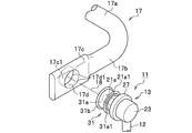
- FIG. 1 is a perspective view illustrating a state in which the stabilizer link 11 is attached to the vehicle.
- the suspension device 15 includes a coil spring 15a and a shock absorber 15b.
- the left and right suspension devices 15 are connected via a stabilizer 17 made of a substantially U-shaped spring steel rod or the like.
- the stabilizer 17 is bent from both ends of the torsion bar portion 17a and the torsion bar portion 17a. And a pair of arm portions 17b extending.
- the stabilizer 17 and the shock absorber 15b that supports the wheel W are connected via a stabilizer link 11.
- the connection is the same on the left and right wheels W side.
- the stabilizer link 11 is configured by providing ball joints 13 at both ends of a substantially linear support bar 12 made of a metal such as steel.
- the ball joint 13 includes a ball stud 21 made of metal such as steel and a housing 23 made of resin, for example.
- the ball stud 21 has a cylindrical stud portion 21a at one end portion and a spherical ball portion 21b at the other end portion.
- the stud portion 21a and the ball portion 21b are joined by welding.
- the stud portion 21a and the ball portion 21b may be integrally formed.
- the housing 23 is provided at both ends of the support bar 12, and is configured to rotatably support the ball portion 21b of the ball stud 21.
- the resin material of the housing 23 for example, fiber reinforced plastic FRP (Fiber-Reinforced Plastics) or carbon fiber reinforced plastic CFRP (Carbon Fiber-Reinforced Plastics) is preferably used.
- the housing 23 is not limited to resin and may be made of metal.
- the configuration of the pair of ball joints 13 is the same.
- the stud portion 21a of the ball stud 21 has a flange portion 21a1 as shown in FIGS. 2A, 2B, and 3 to be described later.
- a circular dust cover 27 made of an elastic material such as rubber is mounted between the disc-shaped flange portion 21a1 provided on the stud portion 21a and one end of the housing 23 so as to cover these gaps. .
- the dust cover 27 plays a role of preventing rainwater, dust and the like from entering the ball joint 13.
- one of the pair of ball joints 13 is fixed to the bracket 15c of the shock absorber 15b by screw fastening.
- the other ball joint 13 is connected to the mounting portion 17c of the arm portion 17b of the stabilizer 17 by the stabilizer link according to the embodiment of the present invention. Bonded using a bonding structure. This will be described in detail below.
- FIGS. 2A, 2B, 3, 4A, 4B, and 4C A stabilizer link joining structure according to an embodiment of the present invention will be described with reference to FIGS. 2A, 2B, 3, 4A, 4B, and 4C.
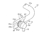
- FIG. 2A and FIG. 2B are perspective views showing a stabilizer link joining structure according to an embodiment of the present invention.
- FIG. 3 is a side view showing a stabilizer link joint structure according to an embodiment of the present invention.
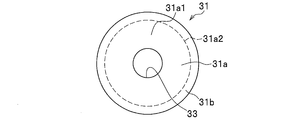
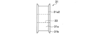
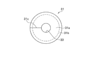
- FIG. 4A is a perspective view of the elastic member 31 that plays an important role in the present invention.
- FIG. 4B is a front view of the elastic member 31.
- FIG. 4C is a side view of the elastic member 31.
- the arm portion 17b of the stabilizer 17 is provided with a flat mounting portion 17c formed by pressing.
- the mounting portion 17c is provided with a through-hole 17d having a shape in which a cylinder just fits.
- the through hole 17d is formed so as to be oriented in a direction orthogonal to the longitudinal direction of the arm portion 17b.
- An elastic member 31 provided on the stud portion 21a of the ball stud 21 is attached to the through hole 17d of the mounting portion 17c.
- the elastic member 31 is not particularly limited.
- natural rubber epoxidized natural rubber, isoprene rubber, butadiene rubber, butadiene / isoprene rubber, styrene / butadiene rubber, chloroprene rubber, acrylonitrile / butadiene rubber (NBR), hydrogenated nitrile.
- rubber elastic resin such as rubber, chlorinated polyethylene rubber, butyl rubber, acrylic rubber, ethylene / vinyl acetate / acrylic ester copolymer rubber, silicone rubber, styrene / butadiene rubber.
- the body portion 31a of the elastic member 31 has a through hole 33 through which the stud portion 21a of the ball stud 21 is inserted so as to penetrate the central portion of the cylindrical shape. It has been established.
- the inner diameter dimension of the through hole 33 provided in the body portion 31a of the elastic member 31 is substantially equal to or slightly larger than the outer diameter dimension of the stud portion 21a.
- the body portion 31 a of the elastic member 31 has a bonding function for firmly bonding the stud portion 21 a of the ball stud 21 to the elastic member 31.
- This bonding function is realized by vulcanizing and bonding the inner wall of the through hole 33 formed in the body portion 31 a to the stud portion 21 a of the ball stud 21.
- an appropriate adhesive layer is applied to both or at least one of the inner wall of the through-hole 33 and the outer wall of the stud portion 21a, thereby interposing an adhesive layer having an appropriate thickness. Done in As shown in FIG.
- This vulcanization adhesion is also performed in a state where an adhesive layer having an appropriate thickness is interposed by applying an appropriate adhesive to both or at least one of the flange side end surface 31a3 and the flange portion 21a1.
- the body portion 31a of the elastic member 31 has a holding function of tightly holding the outer wall through the inner wall of the through hole 17d in a state where the elastic member 31 is mounted in the through hole 17d of the mounting portion 17c.
- This holding function is realized by forming the outer diameter size of the body portion 31a of the elastic member 31 substantially equal to or slightly smaller than the inner diameter size of the through hole 17d of the mounting portion 17c.
- the body part 31a of the elastic member 31 has a vibration-proof function for preventing vibration transmission between the stabilizer link 11 and the stabilizer 17 by being interposed.
- This anti-vibration function is realized with an anti-vibration characteristic according to a spring constant preset in the elastic member 31.
- the ear portion 31b of the elastic member 31 has a drop-off prevention (prevention) function for preventing the stabilizer link 11 from dropping from the mounting portion 17c of the arm portion 17b of the stabilizer 17.
- the ear portion 31b of the elastic member 31 has a peripheral portion 31a2 of a pair of end surfaces 31a1 having a donut shape provided in the body portion 31a, as shown in FIGS. 3, 4A, 4B, and 4C. (See FIG. 4A and FIG. 4B) are integrally formed in an annular shape so as to protrude to the outer peripheral side.
- the ear portion 31b of the elastic member 31 covers the peripheral edge 17d1 (see FIG.
- the elastic member 31 When the elastic member 31 is attached to the through hole 17d of the mounting portion 17c, the elastic member 31 provided on the stud portion 21a of the ball stud 21 is attached to the through hole 17d of the mounting portion 17c with the axial direction 18 ( It only has to be press-fitted along (see FIG. 2A).
- the attachment portion 17c of the arm portion 17b of the stabilizer 17 is fixed to the stud portion 21a of the ball stud 21.
- a force opposite to that at the time of mounting may be applied along the axial direction 18 (see FIG. 2A) of the stud portion 21a using a jig (not shown).
- the detachment load of the vulcanized adhesive part (between the inner side wall of the through hole 33 of the body part 31a and the stud part 21a of the ball stud 21) is the press-fitted part (the inner side wall of the through hole 17d of the mounting part 17c and the body part 31a). It is large compared to the unloading load between the outer walls of Therefore, the elastic member 31 provided in the stud portion 21a can be reliably detached from the through hole 17d of the attachment portion 17c by using the above-described procedure for removing the stabilizer link 11.
- the joint structure of the stabilizer link 11 it is possible to realize simple and firm joining that does not particularly require measures for the stabilizer link 11 to be detached from the stabilizer 17.
- vibration and noise can be suppressed and the ride comfort of the vehicle and the quietness in the passenger compartment can be maintained well.
- the stabilizer link 11 when the stabilizer link 11 is requested to be replaced, the stabilizer link 11 can be easily and reliably detached from the mounting portion 17c. Therefore, when the stabilizer link 11 is requested to be replaced, the stabilizer 17 and the stabilizer link can be removed. Compared with the case where the assembly of 11 assemblies is replaced, the burden on the vehicle user can be greatly reduced.
- the cylindrical member for supporting the elastic member 31 since the cylindrical member for supporting the elastic member 31 is not required, it contributes to the weight reduction and cost reduction of the stabilizer link 11 as one component. Can do. Further, it is possible to expect a secondary effect that the size of the mounting portion 17c, the smoothness around the through-hole 17d provided in the mounting portion 17c, the complexity of managing the coating film thickness, etc. are released. .
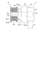
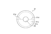
- FIGS. 5A and 5B are explanatory views (front views) according to a modification of the elastic member 31.
- FIG. 5A In the modification of the elastic member 31 shown in FIG. 5A, a slit 31 c is provided along the axial radial direction of the elastic member 31. Thereby, the application
- the elastic member 31 may be equally divided into two at the center line 31d along the axial radial direction of the elastic member 31. If comprised in this way, the application
- drum 31a can be performed more easily. Note that applying an appropriate adhesive to the outer wall of the stud portion 21a as necessary is the same as the example of the elastic member 31 shown in FIG. 4A and the like.
- FIGS. 6A to 6F are explanatory views (side views) according to modifications of the ear portion 31b provided in the elastic member 31.
- edge part 31b facing the side wall 17c1 of the attachment part 17c connected to the peripheral edge 17d1 of the through-hole 17d. (Refer FIG. 6A, FIG. 6B, FIG. 6E) is formed in the standing shape along the side wall 17c1 of the attaching part 17c. If comprised in this way, the force of the direction along the axial direction 18 (refer FIG. 2A) of the stud part 21a with respect to the elastic member 31 will be with the elastic member 31 mounted
- the portion 31b1 (see FIGS. 6A, 6B, and 6E) is formed so as to be directed toward the side wall 17c1 of the mounting portion 17c. If comprised in this way, the force of the direction along the axial direction 18 (refer FIG. 2A) of the stud part 21a with respect to the elastic member 31 will be with the elastic member 31 mounted
- the surface roughness such as sandblast is aimed at improving the adhesion performance using the vulcanization adhesion and the adhesive to the outer peripheral wall (adhesion surface) around the axis.
- the process which roughens is performed.
- surface roughening such as knurling may be performed on the outer peripheral wall (adhesion surface) of the stud portion 21a of the ball stud 21.
- the stabilizer link joining structure according to the present invention (1) is a stabilizer link joining structure for joining the stabilizer link 11 for connecting the suspension device 15 and the stabilizer 17 provided in the vehicle to the stabilizer 17.
- the support bar 12 and ball joints 13 provided at both ends of the support bar 12 are provided.
- the ball joint includes a ball stud 21 having a ball portion 21b and a stud portion 21a, and a housing 23 that rotatably supports the ball portion 21b of the ball stud 21.
- the stabilizer 17 is comprised by metal bar-shaped members. At both ends of the stabilizer 17, attachment portions 17 c to which the stabilizer link 11 is joined are provided.
- the mounting portion 17c is provided with a through hole 17d to which the elastic member 31 provided on the stud portion 21a of the ball stud 21 is mounted.
- the elastic member 31 includes a cylindrical body portion 31a and ear portions 31b provided on each of the peripheral edge portions 31a2 of the pair of donut-shaped end surfaces 31a1 provided in the body portion 31a.
- the stud portion 21a of the ball stud 21 has the body portion 31a abutting against the inner peripheral wall portion of the through hole 17d in a state where the elastic member 31 is mounted in the through hole 17d, and covers the peripheral edge 17d1 of the through hole 17d.
- the ear portion 31b is joined to the mounting portion 17c via the elastic member 31 so that the ear portion 31b is positioned.
- the stabilizer link joining structure according to the present invention (1) it is possible to realize simple and firm joining that does not particularly require measures for dropping the stabilizer link 11 from the stabilizer 17.
- vibration and noise can be suppressed and the ride comfort of the vehicle and the quietness in the passenger compartment can be maintained well.
- the stabilizer link joint structure according to the present invention (2) is the stabilizer link joint structure according to the present invention (1), and the elastic member 31 is a through-hole through which the stud portion 21a of the ball stud 21 is inserted. 33 may be further provided, and the stud portion 21a may be attached to the through hole 33 in a state in which the stud portion 21a is attached to the through hole 33 to be provided in the stud portion 21a.
- the elastic member 31 is provided on the stud portion 21a by being bonded to the through hole 33 in a state where the stud portion 21a is mounted on the through hole 33. Therefore, the elastic member 31 can be reliably fixed to the stud portion 21a.
- the stabilizer link joint structure according to the present invention (3) is the stabilizer link joint structure according to the present invention (2), and the stud portion 21a of the ball stud 21 includes a disk-shaped flange portion 21a1.
- the elastic member 31 may adopt a configuration provided in the stud portion 21a by being bonded to the through hole 33 and the flange portion 21a1 in a state where the stud portion 21a is mounted in the through hole 33.
- the elastic member 31 is bonded to the through hole 33 and the flange portion 21a1 in a state where the stud portion 21a is attached to the through hole 33. Since it is provided in the portion 21a, the elastic member 31 can be more reliably fixed to the stud portion 21a.
- the modification of the ear portion 31b provided in the elastic member 31 of the present invention shown in FIGS. 6A to 6F shows an example of realization of the present invention, and the present invention is not limited to this example.
- any configuration may be adopted as long as it functions to prevent the stabilizer link 11 from falling off (attaching to the mounting portion 17c).
Landscapes
- Engineering & Computer Science (AREA)
- Mechanical Engineering (AREA)
- General Engineering & Computer Science (AREA)
- Vehicle Body Suspensions (AREA)
- Pivots And Pivotal Connections (AREA)
Abstract
スタビリンク(11)は、サポートバー(12)と、ボールジョイント(13)と、を備える。ボールジョイント(13)は、ボール部(21b)及びスタッド部(21a)を有するボールスタッド(21)を備える。スタビライザ(17)の両端にはスタビリンク(11)の取付部(17c)が設けられる。取付部(17c)には、スタッド部(21a)に設けた弾性部材(31)が装着される通孔(17d)が設けられる。弾性部材(31)は、胴体部(31a)と耳部(31b)とを備える。スタッド部(21a)は、弾性部材(31)が通孔(17d)に装着された状態で、通孔(17d)の内周壁部に胴体部(31a)が当接すると共に、通孔(17d)の周端縁部(17d1)を覆って耳部(31b)が位置するように弾性部材(31)を介して取付部(17c)に接合されている。
Description
本発明は、車両に備わる懸架装置とスタビライザの間を連結するためのスタビリンクをスタビライザに接合させるスタビリンクの接合構造に関する。
車両には、路面から車輪を介して車体に伝わる衝撃や振動を吸収し軽減する懸架装置と、車体のロール剛性を高めるためのスタビライザとが備わっている。懸架装置とスタビライザの間を連結するために、車両には、スタビリンクと呼ばれる棒状の部材が用いられる。スタビリンクは、例えば特許文献1に示すように、サポートバーと、サポートバーの両端に設けたボールジョイントとを備えて構成されている。
特許文献1に係るスタビリンクは、ボール部及びスタッド部を有するボールスタッドと、サポートバーの両端に設けられ、ボールスタッドのボール部を回動自在に収容するハウジングとから構成される。ハウジングの内方側には、ハウジングの内壁とボールスタッドのボール部との間に介在するように、樹脂製のボールシートが設けられている。
特許文献1に係るスタビリンクをスタビライザに接合するために、スタビライザの両端には、プレス加工により形成された平板状の取付部がそれぞれ設けられている。一対の取付部には通孔がそれぞれ開設されている。スタビライザの取付部に開設された通孔に、ボールスタッドのスタッド部が貫通される。通孔から突出したスタッド部の貫通側に設けた雄ねじにはナットの雌ねじが螺合される。かかるねじ締結を用いてスタビライザがスタビリンクに接合される。
しかしながら、特許文献1に係るスタビリンクのねじ締結を用いた接合構造では、スタッド部の雄ねじに対するナットの雌ねじの緩みがもたらすスタビライザからのスタビリンクの脱落対策が必須である。そのため、例えば、取付部のサイズ、取付部に開設した通孔周辺の平滑度、塗料の膜厚等を緻密に管理することを要する。その結果、スタビライザからのスタビリンクの脱落対策が煩雑である点で改良の余地があった。
本発明は上記実情に鑑みて創案されたものであり、スタビライザからのスタビリンクの脱落対策を特に要しない簡易かつ堅固な接合を実現可能なスタビリンクの接合構造を提供することを目的とする。
前記課題を解決するため、本発明(1)に係るスタビリンクの接合構造は、車両に備わる懸架装置及びスタビライザを連結するためのスタビリンクを前記スタビライザに接合させるスタビリンクの接合構造であって、前記スタビリンクは、サポートバーと、当該サポートバーの両端に設けたボールジョイントと、を備え、前記ボールジョイントは、ボール部及びスタッド部を有するボールスタッドと、当該ボールスタッドの前記ボール部を回動自在に支持するハウジングと、を備え、前記スタビライザは、金属製の棒状部材により構成され、前記スタビライザの両端には、前記スタビリンクが接合される取付部がそれぞれ設けられ、前記取付部には、前記ボールスタッドの前記スタッド部に設けた弾性部材が装着される通孔がそれぞれ設けられ、前記弾性部材は、円筒形状の胴体部と、前記胴体部に備わる一対の外周縁部のそれぞれに設けられる耳部と、を備え、前記ボールスタッドの前記スタッド部は、前記弾性部材が前記通孔に装着された状態で、当該通孔の内周壁部に前記胴体部が当接すると共に、当該通孔に備わる一対の外周縁部を覆って前記耳部が位置するように当該弾性部材を介して前記取付部に接合されていることを最も主要な特徴とする。
本発明(1)に係るスタビリンクの接合構造によれば、ボールスタッドのスタッド部は、弾性部材が通孔に装着された状態で、通孔の内周壁部に胴体部が当接すると共に、通孔に備わる一対の外周縁部を覆って耳部が位置するように弾性部材を介して取付部に接合されているため、スタビライザからのスタビリンクの脱落対策を特に要しない簡易かつ堅固な接を実現することができる。
本発明によれば、スタビライザからのスタビリンクの脱落対策を特に要しない簡易かつ堅固な接合を実現可能なスタビリンクの接合構造を提供することができる。
以下、本発明の実施形態に係るスタビリンクの接合構造について、適宜図面を参照しながら詳細に説明する。
なお、以下に示す図において、共通の機能を有する部材間、又は、相互に対応する機能を有する部材間には、原則として共通の参照符号を付するものとする。また、説明の便宜のため、部材のサイズ及び形状は、変形または誇張して模式的に表す場合がある。
なお、以下に示す図において、共通の機能を有する部材間、又は、相互に対応する機能を有する部材間には、原則として共通の参照符号を付するものとする。また、説明の便宜のため、部材のサイズ及び形状は、変形または誇張して模式的に表す場合がある。
<スタビリンク11及びその周辺の構成>
はじめに、スタビリンク11及びその周辺の構成について、スタビリンク11を車両(不図示)に取付けた例をあげて説明する。図1は、スタビリンク11の車両への取り付け状態を表す斜視図である。
はじめに、スタビリンク11及びその周辺の構成について、スタビリンク11を車両(不図示)に取付けた例をあげて説明する。図1は、スタビリンク11の車両への取り付け状態を表す斜視図である。
車両の車体(不図示)には、図1に示すように、懸架装置15を介して、車輪Wが取り付けられている。路面から車輪Wを介して車体に伝わる衝撃や振動を吸収し軽減するために、懸架装置15は、コイルスプリング15aとショックアブソーバ15bとを有する。
左右の懸架装置15の間は、図1に示すように、略コ字形状のばね鋼棒等からなるスタビライザ17を介して連結されている。車体のロール剛性(捩り変形に対する抵抗力)を高めて車両のローリングを抑制するために、スタビライザ17は、左右の車輪W間に延在するトーションバー部17aと、トーションバー部17aの両端から屈曲して延びる一対のアーム部17bとを有する。
スタビライザ17と、車輪Wを支持するショックアブソーバ15bとの間は、スタビリンク11を介して連結されている。当該連結は、左右の車輪W側において同じである。スタビリンク11は、図1に示すように、例えば鉄鋼等の金属からなる略直線状のサポートバー12の両端に、ボールジョイント13をそれぞれ設けて構成されている。
ボールジョイント13は、後記する図3に示すように、鋼等の金属製のボールスタッド21と、例えば樹脂製のハウジング23とから構成される。ボールスタッド21は、一方の端部に円柱状のスタッド部21aを有すると共に、他方の端部に球状のボール部21bを有して構成されている。スタッド部21aとボール部21bとは溶接接合されている。スタッド部21aとボール部21bとを一体に形成してもよい。ハウジング23は、サポートバー12の両端に設けられ、ボールスタッド21のボール部21bを回動自在に支持するように構成されている。ハウジング23の樹脂素材としては、例えば、繊維強化プラスチックFRP(Fiber-Reinforced Plastics)、炭素繊維強化プラスチックCFRP(Carbon Fiber-Reinforced Plastics)が好適に用いられる。ただし、ハウジング23は樹脂製に限らず、金属製であってもよい。なお、一対のボールジョイント13の構成は同じである。
ボールスタッド21のスタッド部21aは、後記する図2A、図2B、図3に示すように、フランジ部21a1を有して構成されている。スタッド部21aに設けた円板形状のフランジ部21a1と、ハウジング23の一端との間には、これらの隙間を覆うように、ゴム等の弾性体からなる周回状のダストカバー27が装着される。ダストカバー27は、雨水、塵埃等のボールジョイント13への侵入を阻止する役割を果たす。
一対のボールジョイント13のうち一方のボールジョイント13は、図1に示すように、ショックアブソーバ15bのブラケット15cにねじ締結により固定される。また、他方のボールジョイント13は、例えば図1、図2A、図2B、図3に示すように、スタビライザ17におけるアーム部17bが有する取付部17cに対し、本発明の実施形態に係るスタビリンクの接合構造を用いて接合される。これについて、詳しくは次述する。
<本発明の実施形態に係るスタビリンクの接合構造>
本発明の実施形態に係るスタビリンクの接合構造について、図2A、図2B、図3、図4A、図4B、図4Cを参照して説明する。図2A、図2Bは、本発明の実施形態に係るスタビリンクの接合構造を表す斜視図である。図3は、本発明の実施形態に係るスタビリンクの接合構造を表す側面図である。図4Aは、本発明において重要な役割を果たす弾性部材31の斜視図である。図4Bは、弾性部材31の正面図である。図4Cは、弾性部材31の側面図である。
本発明の実施形態に係るスタビリンクの接合構造について、図2A、図2B、図3、図4A、図4B、図4Cを参照して説明する。図2A、図2Bは、本発明の実施形態に係るスタビリンクの接合構造を表す斜視図である。図3は、本発明の実施形態に係るスタビリンクの接合構造を表す側面図である。図4Aは、本発明において重要な役割を果たす弾性部材31の斜視図である。図4Bは、弾性部材31の正面図である。図4Cは、弾性部材31の側面図である。
スタビライザ17におけるアーム部17bには、図2A,図2B,図3に示すように、プレス加工により形成された平板状の取付部17cが設けられている。取付部17cには、円柱がちょうど嵌まる形状の通孔17dが開設されている。通孔17dは、アーム部17bの長手方向に直交する向きを指向するように形成されている。取付部17cの通孔17dには、ボールスタッド21のスタッド部21aに設けた弾性部材31が装着される。
弾性部材31は、特に限定されないが、例えば、天然ゴム、エポキシ化天然ゴム、イソプレンゴム、ブタジエンゴム、ブタジエン・イソプレンゴム、スチレン・ブタジエンゴム、クロロプレンゴム、アクリロニトリル・ブタジエンゴム(NBR)、水素添加ニトリルゴム、塩素化ポリエチレンゴム、ブチルゴム、アクリルゴム、エチレン・酢酸ビニル・アクリル酸エステル共重合ゴム、シリコーンゴム、スチレン・ブタジエンゴム等のゴム弾性樹脂で構成される。
弾性部材31の胴体部31aには、図3、図4A、図4B、図4Cに示すように、円筒形状の中央部分を貫くようにボールスタッド21のスタッド部21aが挿通される貫通孔33が開設されている。弾性部材31の胴体部31aに開設された貫通孔33の内径寸法は、スタッド部21aの外径寸法と比べて、実質的に同等、又は僅かに大きく形成されている。
弾性部材31の胴体部31aは、ボールスタッド21のスタッド部21aを弾性部材31に強固に接着させる接着機能を有する。この接着機能は、胴体部31aに開設された貫通孔33の内側壁を、ボールスタッド21のスタッド部21aに加硫接着することで実現される。この加硫接着は、貫通孔33の内側壁及びスタッド部21aの外側壁の両者又は少なくともいずれか一方に適宜の接着剤を塗布することにより、適宜の厚さの接着剤層を介在させた状態で行われる。
なお、図3に示すように、胴体部31aに備わるドーナツ形状の一対の端面31a1のうちフランジ部21a1に対向する側のフランジ側端面31a3を、スタッド部21aに設けた円板形状のフランジ部21a1に加硫接着することで、胴体部31aが有する接着機能を強化するように構成してもよい。この加硫接着も、フランジ側端面31a3及びフランジ部21a1の両者又は少なくともいずれか一方に適宜の接着剤を塗布することにより、適宜の厚さの接着剤層を介在させた状態で行われる。
なお、図3に示すように、胴体部31aに備わるドーナツ形状の一対の端面31a1のうちフランジ部21a1に対向する側のフランジ側端面31a3を、スタッド部21aに設けた円板形状のフランジ部21a1に加硫接着することで、胴体部31aが有する接着機能を強化するように構成してもよい。この加硫接着も、フランジ側端面31a3及びフランジ部21a1の両者又は少なくともいずれか一方に適宜の接着剤を塗布することにより、適宜の厚さの接着剤層を介在させた状態で行われる。
また、弾性部材31の胴体部31aは、取付部17cの通孔17dに弾性部材31が装着された状態で、その外側壁を通孔17dの内側壁に密着保持させる保持機能を有する。この保持機能は、弾性部材31の胴体部31aの外径寸法を、取付部17cの通孔17dの内径寸法と比べて、実質的に同等、又は、僅かに小さく形成することで実現される。
さらに、弾性部材31の胴体部31aは、スタビリンク11とスタビライザ17との間に介在することで両者間の振動伝達を防ぐ防振機能を有する。この防振機能は、弾性部材31に予め設定されるばね定数に従う防振特性をもって実現される。
弾性部材31の耳部31bは、スタビライザ17におけるアーム部17bが有する取付部17cからのスタビリンク11の脱落を防止する脱落防止(抜け止め)機能を有する。この抜け止め機能を果たすために、弾性部材31の耳部31bは、図3、図4A、図4B、図4Cに示すように、胴体部31aに備わるドーナツ形状の一対の端面31a1の周縁部31a2(図4A、図4B参照)のそれぞれに対して外周側に突き出すように、環状に一体形成されている。
弾性部材31の耳部31bは、図2Bに示すように、弾性部材31が取付部17cの通孔17dに装着された状態で、通孔17dの周端縁部17d1(図2A参照)を覆って耳部31bが位置するように構成されている。
これにより、仮に、弾性部材31に対してスタッド部21aの軸線方向18(図2A参照)に沿う向きの力が作用したとしても、弾性部材31の耳部31bが、通孔17dの周端縁部17d1に連なる取付部17cの側壁17c1(図2A、図2B参照)に突き当たることで立体障害となって、前記の力をいなすと共に、取付部17cの通孔17dから弾性部材31が脱落する事態を未然に防止することができる。
弾性部材31の耳部31bは、図2Bに示すように、弾性部材31が取付部17cの通孔17dに装着された状態で、通孔17dの周端縁部17d1(図2A参照)を覆って耳部31bが位置するように構成されている。
これにより、仮に、弾性部材31に対してスタッド部21aの軸線方向18(図2A参照)に沿う向きの力が作用したとしても、弾性部材31の耳部31bが、通孔17dの周端縁部17d1に連なる取付部17cの側壁17c1(図2A、図2B参照)に突き当たることで立体障害となって、前記の力をいなすと共に、取付部17cの通孔17dから弾性部材31が脱落する事態を未然に防止することができる。
取付部17cの通孔17dに弾性部材31を装着するに際しては、取付部17cの通孔17dに対し、ボールスタッド21のスタッド部21aに設けた弾性部材31を、スタッド部21aの軸線方向18(図2A参照)に沿って圧入すればよい。
また、例えばスタビリンク11の交換要請が生じて取付部17cからスタビリンク11を離脱させるに際しては、スタビライザ17におけるアーム部17bが有する取付部17cを固定した状態で、ボールスタッド21のスタッド部21aに対し、不図示の治具を用いてスタッド部21aの軸線方向18(図2A参照)に沿って装着(圧入)時と逆向きの力を加えればよい。
ちなみに、加硫接着部(胴体部31aの貫通孔33の内側壁及びボールスタッド21のスタッド部21aの間)の抜け荷重は、圧入部(取付部17cの通孔17dの内側壁及び胴体部31aの外側壁の間)の抜け荷重と比べて大きい。そのため、前記したスタビリンク11の離脱手順を用いることにより、取付部17cの通孔17dからスタッド部21aに設けた弾性部材31を確実に離脱させることができる。
ちなみに、加硫接着部(胴体部31aの貫通孔33の内側壁及びボールスタッド21のスタッド部21aの間)の抜け荷重は、圧入部(取付部17cの通孔17dの内側壁及び胴体部31aの外側壁の間)の抜け荷重と比べて大きい。そのため、前記したスタビリンク11の離脱手順を用いることにより、取付部17cの通孔17dからスタッド部21aに設けた弾性部材31を確実に離脱させることができる。
本発明の実施形態に係るスタビリンク11の接合構造によれば、スタビライザ17からのスタビリンク11の脱落対策を特に要しない簡易かつ堅固な接合を実現することができる。
また、振動や騒音を抑制して車両の乗り心地や車室内の静粛性を良好に保持することができる。
さらに、例えばスタビリンク11の交換要請が生じた際に、取付部17cからスタビリンク11を簡易かつ確実に離脱させることができるため、スタビリンク11の交換要請が生じた際にスタビライザ17及びスタビリンク11の組立体をアッセンブリ交換する場合と比べて、車両ユーザの負担を大幅に軽減することができる。
また、本発明の実施形態に係るスタビリンク11の接合構造では、弾性部材31を支持するための筒状部材を要しないため、一部品としてのスタビリンク11の軽量化及びコスト削減に貢献することができる。
さらに、取付部17cのサイズ、取付部17cに開設した通孔17d周辺の平滑度、塗料の膜厚等を緻密に管理する煩雑さから解放されるという副次的な効果を期待することができる。
<弾性部材31の変形例>
次に、弾性部材31の変形例について、図5A、図5Bを参照して説明する。図5A、図5Bは、弾性部材31の変形例に係る説明図(正面図)である。
図5Aに示す弾性部材31の変形例では、弾性部材31の軸放射方向に沿ってスリット31cが設けられている。これにより、スリット31cの部位を押し広げることにより、胴体部31aにおける貫通孔33の内側壁に対する接着剤の塗布作業を容易に行うことができる。
また、図5Bに示す弾性部材31の変形例のように、弾性部材31の軸放射方向に沿う中心線31dの部位で弾性部材31をふたつに均等分割してもよい。このように構成すれば、胴体部31aにおける貫通孔33の内側壁に対する接着剤の塗布作業を一層容易に行うことができる。
なお、必要に応じて、スタッド部21aの外側壁にも適宜の接着剤を塗布することは、図4A等に示す弾性部材31の例と同じである。
<弾性部材31に備わる耳部31bの変形例>
次に、弾性部材31に備わる耳部31bの変形例について、図6A~図6Fを参照して説明する。図6A~図6Fは、弾性部材31に備わる耳部31bの変形例に係る説明図(側面図)である。なお、図6A~図6Fでは、取付部17cの通孔17dと、弾性部材31の耳部31bとの位置関係を、説明の便宜を図る目的で相互の中心軸(本来であれば一致)を軸放射方向にずらして表現している。
図6A、図6B、図6Eに示す弾性部材31に備わる耳部31bの変形例では、通孔17dの周端縁部17d1に連なる取付部17cの側壁17c1に対面する耳部31bにおける内耳部31b1(図6A、図6B、図6E参照)は、取付部17cの側壁17c1に沿う起立形状に形成されている。
このように構成すれば、仮に、取付部17cの通孔17dに弾性部材31が装着された状態で、弾性部材31に対してスタッド部21aの軸線方向18(図2A参照)に沿う向きの力が作用したとしても、弾性部材31の耳部31bに起立形成された内耳部31b1が、通孔17dの周端縁部17d1に連なる取付部17cの側壁17c1に突き当たることで強い立体障害となる。その結果、前記の力をいなすと共に、取付部17cの通孔17dから弾性部材31が脱落する事態を確実に予防することができる。
また、図6C、図6D、図6Fに示す弾性部材31に備わる耳部31bの変形例では、通孔17dの周端縁部17d1に連なる取付部17cの側壁17c1に対面する耳部31bにおける内耳部31b1(図6A、図6B、図6E参照)は、取付部17cの側壁17c1の側を指向するように傾斜形成されている。
このように構成すれば、仮に、取付部17cの通孔17dに弾性部材31が装着された状態で、弾性部材31に対してスタッド部21aの軸線方向18(図2A参照)に沿う向きの力が作用したとしても、弾性部材31の耳部31bに傾斜形成された内耳部31b1が、通孔17dの周端縁部17d1に連なる取付部17cの側壁17c1に強く突き当たることでより強い立体障害となる。その結果、前記の力をいなすと共に、取付部17cの通孔17dから弾性部材31が脱落する事態を一層確実に予防することができる。
このように構成すれば、仮に、取付部17cの通孔17dに弾性部材31が装着された状態で、弾性部材31に対してスタッド部21aの軸線方向18(図2A参照)に沿う向きの力が作用したとしても、弾性部材31の耳部31bに傾斜形成された内耳部31b1が、通孔17dの周端縁部17d1に連なる取付部17cの側壁17c1に強く突き当たることでより強い立体障害となる。その結果、前記の力をいなすと共に、取付部17cの通孔17dから弾性部材31が脱落する事態を一層確実に予防することができる。
<ボールスタッド21のスタッド部21aの変形例>
次に、ボールスタッド21のスタッド部21aの変形例について説明する。変形例に係るボールスタッド21のスタッド部21aでは、その軸周りの外周壁(接着面)に対して、加硫接着及び接着剤を用いた接着性能の向上を狙って、サンドブラスト等の表面粗さを粗くする処理が施されている。
なお、表面粗さを粗くする処理に代えて、又は加えて、ボールスタッド21のスタッド部21aにおける外周壁(接着面)に対し、ローレット加工等の表面粗し加工を施しても構わない。
次に、ボールスタッド21のスタッド部21aの変形例について説明する。変形例に係るボールスタッド21のスタッド部21aでは、その軸周りの外周壁(接着面)に対して、加硫接着及び接着剤を用いた接着性能の向上を狙って、サンドブラスト等の表面粗さを粗くする処理が施されている。
なお、表面粗さを粗くする処理に代えて、又は加えて、ボールスタッド21のスタッド部21aにおける外周壁(接着面)に対し、ローレット加工等の表面粗し加工を施しても構わない。
〔本発明の実施形態に係るスタビリンクの接合構造が奏する作用効果〕
次に、本発明の実施形態に係るスタビリンクの接合構造が奏する作用効果について説明する。
次に、本発明の実施形態に係るスタビリンクの接合構造が奏する作用効果について説明する。
本発明(1)に係るスタビリンクの接合構造は、車両に備わる懸架装置15及びスタビライザ17を連結するためのスタビリンク11をスタビライザ17に接合させるスタビリンクの接合構造であって、スタビリンク11は、サポートバー12と、サポートバー12の両端に設けたボールジョイント13と、を備える。
ボールジョイントは、ボール部21b及びスタッド部21aを有するボールスタッド21と、ボールスタッド21のボール部21bを回動自在に支持するハウジング23と、を備える。
スタビライザ17は、金属製の棒状部材により構成される。スタビライザ17の両端には、スタビリンク11が接合される取付部17cがそれぞれ設けられている。取付部17cには、ボールスタッド21のスタッド部21aに設けた弾性部材31が装着される通孔17dがそれぞれ設けられている。
弾性部材31は、円筒形状の胴体部31aと、胴体部31aに備わる一対のドーナツ形状の端面31a1の周縁部31a2のそれぞれに設けられる耳部31bと、を備える。
ボールスタッド21のスタッド部21aは、弾性部材31が通孔17dに装着された状態で、通孔17dの内周壁部に胴体部31aが当接すると共に、通孔17dの周端縁部17d1を覆って耳部31bが位置するように弾性部材31を介して取付部17cに接合されている。
本発明(1)に係るスタビリンクの接合構造によれば、スタビライザ17からのスタビリンク11の脱落対策を特に要しない簡易かつ堅固な接合を実現することができる。また、振動や騒音を抑制して車両の乗り心地や車室内の静粛性を良好に保持することができる。
また、本発明(2)に係るスタビリンクの接合構造は、本発明(1)に係るスタビリンクの接合構造であって、弾性部材31は、ボールスタッド21のスタッド部21aが挿通される貫通孔33をさらに備え、スタッド部21aが貫通孔33に装着された状態で当該貫通孔33に接着されることで当該スタッド部21aに設けられている構成を採用してもよい。
本発明(2)に係るスタビリンクの接合構造によれば、弾性部材31は、スタッド部21aが貫通孔33に装着された状態で当該貫通孔33に接着されることで当該スタッド部21aに設けられているため、スタッド部21aに対して弾性部材31を確実に固定することができる。
また、本発明(3)に係るスタビリンクの接合構造は、本発明(2)に係るスタビリンクの接合構造であって、ボールスタッド21のスタッド部21aは、円板形状のフランジ部21a1を備え、弾性部材31は、スタッド部21aが貫通孔33に装着された状態で当該貫通孔33及びフランジ部21a1に接着されることで当該スタッド部21aに設けられている構成を採用してもよい。
本発明(3)に係るスタビリンクの接合構造によれば、弾性部材31は、スタッド部21aが貫通孔33に装着された状態で当該貫通孔33及びフランジ部21a1に接着されることで当該スタッド部21aに設けられているため、スタッド部21aに対して弾性部材31を一層確実に固定することができる。
〔その他の実施形態〕
以上説明した複数の実施形態は、本発明の具現化の例を示したものである。したがって、これらによって本発明の技術的範囲が限定的に解釈されることがあってはならない。本発明はその要旨又はその主要な特徴から逸脱することなく、様々な形態で実施することができるからである。
以上説明した複数の実施形態は、本発明の具現化の例を示したものである。したがって、これらによって本発明の技術的範囲が限定的に解釈されることがあってはならない。本発明はその要旨又はその主要な特徴から逸脱することなく、様々な形態で実施することができるからである。
例えば、本発明の弾性部材31に備わる耳部31bの変形例の説明において、図6A~図6Fにそれぞれ示す耳部31bの内耳部31b1が呈する形状(起立形状又は傾斜形状)として、ひとつの弾性部材31に対して同一の形状を採用する例をあげて説明したが、本発明はこの例に限定されない。ひとつの弾性部材31に対して、相互に異なる形状を呈する耳部31bの内耳部31b1を設ける構成を採用しても構わない。
また、図6A~図6Fに示した本発明の弾性部材31に備わる耳部31bの変形例は、本発明の具現化の例を示したものであって、本発明はこの例に限定されない。本発明の弾性部材31に備わる耳部31bの構成について、取付部17cからのスタビリンク11の脱落防止(抜け止め)機能を果たす限りにおいて、いかなる構成を採用して構わない。
11 スタビリンク
12 サポートバー
13 ボールジョイント
15 懸架装置
17 スタビライザ
17c 取付部
17d 通孔
17d1 通孔の周端縁部
21 ボールスタッド
21a スタッド部
21a1 フランジ部
21b ボール部
23 ハウジング
31 弾性部材
31a 胴体部
31a1 胴体部の一対の端面
31a2 端面の周縁部
31a3 フランジ側端面
31b 耳部
33 貫通孔
12 サポートバー
13 ボールジョイント
15 懸架装置
17 スタビライザ
17c 取付部
17d 通孔
17d1 通孔の周端縁部
21 ボールスタッド
21a スタッド部
21a1 フランジ部
21b ボール部
23 ハウジング
31 弾性部材
31a 胴体部
31a1 胴体部の一対の端面
31a2 端面の周縁部
31a3 フランジ側端面
31b 耳部
33 貫通孔
Claims (3)
- 車両に備わる懸架装置及びスタビライザを連結するためのスタビリンクを前記スタビライザに接合させるスタビリンクの接合構造であって、
前記スタビリンクは、サポートバーと、当該サポートバーの両端に設けたボールジョイントと、を備え、
前記ボールジョイントは、ボール部及びスタッド部を有するボールスタッドと、当該ボールスタッドの前記ボール部を回動自在に支持するハウジングと、を備え、
前記スタビライザは、金属製の棒状部材により構成され、
前記スタビライザの両端には、前記スタビリンクが接合される取付部がそれぞれ設けられ、
前記取付部には、前記ボールスタッドの前記スタッド部に設けた弾性部材が装着される通孔がそれぞれ設けられ、
前記弾性部材は、円筒形状の胴体部と、前記胴体部に備わる一対の外周縁部のそれぞれに設けられる耳部と、を備え、
前記ボールスタッドの前記スタッド部は、前記弾性部材が前記通孔に装着された状態で、当該通孔の内周壁部に前記胴体部が当接すると共に、当該通孔に備わる一対の外周縁部を覆って前記耳部が位置するように当該弾性部材を介して前記取付部に接合されている
ことを特徴とするスタビリンクの接合構造。 - 請求項1に記載のスタビリンクの接合構造であって、
前記弾性部材は、前記ボールスタッドの前記スタッド部が挿通される貫通孔をさらに備え、当該スタッド部が当該貫通孔に装着された状態で当該貫通孔に接着されることで当該スタッド部に設けられている
ことを特徴とするスタビリンクの接合構造。 - 請求項2に記載のスタビリンクの接合構造であって、
前記ボールスタッドの前記スタッド部は、円板形状のフランジ部を備え、
前記弾性部材は、前記ボールスタッドの前記スタッド部が前記貫通孔に装着された状態で当該貫通孔及び前記フランジ部に接着されることで当該スタッド部に設けられている
ことを特徴とするスタビリンクの接合構造。
Priority Applications (4)
| Application Number | Priority Date | Filing Date | Title |
|---|---|---|---|
| US16/617,761 US20200171910A1 (en) | 2017-06-02 | 2018-05-09 | Joint structure of stabilizer link |
| EP18810566.2A EP3632717B1 (en) | 2017-06-02 | 2018-05-09 | Joint structure of stabilizer link |
| KR1020197031990A KR102238853B1 (ko) | 2017-06-02 | 2018-05-09 | 스태빌라이저 링크의 접합 구조 |
| CN201880035056.7A CN110709264B (zh) | 2017-06-02 | 2018-05-09 | 稳定器连杆的接合构造 |
Applications Claiming Priority (2)
| Application Number | Priority Date | Filing Date | Title |
|---|---|---|---|
| JP2017110408A JP6904790B2 (ja) | 2017-06-02 | 2017-06-02 | スタビリンクの接合構造 |
| JP2017-110408 | 2017-06-02 |
Publications (1)
| Publication Number | Publication Date |
|---|---|
| WO2018221147A1 true WO2018221147A1 (ja) | 2018-12-06 |
Family
ID=64455889
Family Applications (1)
| Application Number | Title | Priority Date | Filing Date |
|---|---|---|---|
| PCT/JP2018/018010 WO2018221147A1 (ja) | 2017-06-02 | 2018-05-09 | スタビリンクの接合構造 |
Country Status (6)
| Country | Link |
|---|---|
| US (1) | US20200171910A1 (ja) |
| EP (1) | EP3632717B1 (ja) |
| JP (1) | JP6904790B2 (ja) |
| KR (1) | KR102238853B1 (ja) |
| CN (1) | CN110709264B (ja) |
| WO (1) | WO2018221147A1 (ja) |
Families Citing this family (1)
| Publication number | Priority date | Publication date | Assignee | Title |
|---|---|---|---|---|
| JP7162573B2 (ja) * | 2019-07-02 | 2022-10-28 | 日本発條株式会社 | スタビライザ |
Citations (7)
| Publication number | Priority date | Publication date | Assignee | Title |
|---|---|---|---|---|
| JPH05141462A (ja) * | 1991-11-20 | 1993-06-08 | Bridgestone Corp | 筒形防振ゴム |
| JPH0713514U (ja) * | 1993-08-20 | 1995-03-07 | 日産ディーゼル工業株式会社 | ローリングスタビライザ装置 |
| JP2002174283A (ja) * | 2000-12-04 | 2002-06-21 | Nissan Diesel Motor Co Ltd | ブッシュ |
| JP2007331617A (ja) * | 2006-06-15 | 2007-12-27 | Toyota Motor Corp | スタビライザ装置 |
| KR20080023429A (ko) * | 2006-09-11 | 2008-03-14 | 현대자동차주식회사 | 스테빌라이저 엔드부의 마운팅 |
| JP2015151097A (ja) * | 2014-02-18 | 2015-08-24 | 日本発條株式会社 | リンクアーム部材、及び、リンクアーム部材の製造方法 |
| JP2016084057A (ja) | 2014-10-28 | 2016-05-19 | 日本発條株式会社 | リンクアーム部材 |
Family Cites Families (10)
| Publication number | Priority date | Publication date | Assignee | Title |
|---|---|---|---|---|
| US4067525A (en) * | 1976-11-18 | 1978-01-10 | Bushings, Inc. | Resilient mounting |
| JPS5854246Y2 (ja) * | 1980-02-19 | 1983-12-10 | 中央発條株式会社 | 車輪懸架装置用中空スタビライザ |
| JP2575970Y2 (ja) * | 1993-02-25 | 1998-07-02 | 丸五ゴム工業株式会社 | スタビライザの軸受装置 |
| JP3701702B2 (ja) * | 1994-09-30 | 2005-10-05 | 中央発條株式会社 | 自動車用スタビライザ装置 |
| JPH11139129A (ja) * | 1997-09-08 | 1999-05-25 | Toyoda Gosei Co Ltd | サスペンション用リンク機構 |
| JP3848556B2 (ja) * | 2001-10-18 | 2006-11-22 | 日本発条株式会社 | 中空スタビライザ |
| JP4961775B2 (ja) * | 2006-03-07 | 2012-06-27 | 住友電気工業株式会社 | 鉄道車両用のリンクおよびその製造方法 |
| US20080163453A1 (en) * | 2007-01-09 | 2008-07-10 | Jerry Joseph | Bushing for suspension system |
| US7914023B2 (en) * | 2009-03-13 | 2011-03-29 | GM Global Technology Operations LLC | Parallelogram-style steering mechanism having a relay rod bushing |
| JP5926763B2 (ja) * | 2014-04-24 | 2016-05-25 | 日本発條株式会社 | ゴムブッシュ付きスタビライザーバーの製造方法 |
-
2017
- 2017-06-02 JP JP2017110408A patent/JP6904790B2/ja active Active
-
2018
- 2018-05-09 CN CN201880035056.7A patent/CN110709264B/zh active Active
- 2018-05-09 EP EP18810566.2A patent/EP3632717B1/en active Active
- 2018-05-09 KR KR1020197031990A patent/KR102238853B1/ko active IP Right Grant
- 2018-05-09 US US16/617,761 patent/US20200171910A1/en not_active Abandoned
- 2018-05-09 WO PCT/JP2018/018010 patent/WO2018221147A1/ja unknown
Patent Citations (7)
| Publication number | Priority date | Publication date | Assignee | Title |
|---|---|---|---|---|
| JPH05141462A (ja) * | 1991-11-20 | 1993-06-08 | Bridgestone Corp | 筒形防振ゴム |
| JPH0713514U (ja) * | 1993-08-20 | 1995-03-07 | 日産ディーゼル工業株式会社 | ローリングスタビライザ装置 |
| JP2002174283A (ja) * | 2000-12-04 | 2002-06-21 | Nissan Diesel Motor Co Ltd | ブッシュ |
| JP2007331617A (ja) * | 2006-06-15 | 2007-12-27 | Toyota Motor Corp | スタビライザ装置 |
| KR20080023429A (ko) * | 2006-09-11 | 2008-03-14 | 현대자동차주식회사 | 스테빌라이저 엔드부의 마운팅 |
| JP2015151097A (ja) * | 2014-02-18 | 2015-08-24 | 日本発條株式会社 | リンクアーム部材、及び、リンクアーム部材の製造方法 |
| JP2016084057A (ja) | 2014-10-28 | 2016-05-19 | 日本発條株式会社 | リンクアーム部材 |
Also Published As
| Publication number | Publication date |
|---|---|
| KR20190127958A (ko) | 2019-11-13 |
| KR102238853B1 (ko) | 2021-04-09 |
| EP3632717A4 (en) | 2021-03-03 |
| CN110709264B (zh) | 2023-02-17 |
| EP3632717A1 (en) | 2020-04-08 |
| EP3632717B1 (en) | 2023-11-15 |
| US20200171910A1 (en) | 2020-06-04 |
| CN110709264A (zh) | 2020-01-17 |
| JP6904790B2 (ja) | 2021-07-21 |
| JP2018203033A (ja) | 2018-12-27 |
Similar Documents
| Publication | Publication Date | Title |
|---|---|---|
| KR101538422B1 (ko) | 비틀림 슬립을 갖는 굴곡된 부싱 | |
| WO2014192081A1 (ja) | 車両用リンク部品およびその製造方法 | |
| US11560030B2 (en) | Arm support structure | |
| WO2018221147A1 (ja) | スタビリンクの接合構造 | |
| US20210276390A1 (en) | Stabilizer manufacturing method, and joint structure for stabilizer link | |
| JP2003294084A (ja) | 防振ブッシュ | |
| JP5998162B2 (ja) | ショックアブソーバ | |
| JP2017067293A (ja) | シャーシ軸受 | |
| JP5197585B2 (ja) | 機器固定用ブッシュ及びそれを用いた機器固定装置 | |
| JP2008173990A (ja) | プロペラシャフトの支持構造 | |
| JP2008291973A (ja) | 防振装置 | |
| JP2008106867A (ja) | ストラットマウント | |
| JP2007302110A (ja) | 車両用操舵装置 | |
| JPH08219210A (ja) | 防振支持体 | |
| JP4543318B2 (ja) | ダイナミックダンパ | |
| JP2007022418A (ja) | 車高センサのリンクアーム固定構造 | |
| KR101753790B1 (ko) | 엔드플레이트와 스토퍼가 일체형으로 형성되는 롤로드 | |
| JP6975030B2 (ja) | 防振装置及び防振構造 | |
| JP5546467B2 (ja) | ボールジョイント部材の取付構造 | |
| JP2018091463A (ja) | 防振ブッシュ | |
| JP2006315435A (ja) | サスペンション構造 | |
| JPH11182601A (ja) | 防振装置 | |
| JPH0565640U (ja) | センタベアリングのブラケット支持構造 | |
| JPH09257074A (ja) | 防振装置 | |
| JP2015025540A (ja) | 防振装置 |
Legal Events
| Date | Code | Title | Description |
|---|---|---|---|
| 121 | Ep: the epo has been informed by wipo that ep was designated in this application |
Ref document number: 18810566 Country of ref document: EP Kind code of ref document: A1 |
|
| ENP | Entry into the national phase |
Ref document number: 20197031990 Country of ref document: KR Kind code of ref document: A |
|
| NENP | Non-entry into the national phase |
Ref country code: DE |
|
| ENP | Entry into the national phase |
Ref document number: 2018810566 Country of ref document: EP Effective date: 20200102 |