EP3630573B1 - Untergestell für einen plattformwagen - Google Patents
Untergestell für einen plattformwagen Download PDFInfo
- Publication number
- EP3630573B1 EP3630573B1 EP18728128.2A EP18728128A EP3630573B1 EP 3630573 B1 EP3630573 B1 EP 3630573B1 EP 18728128 A EP18728128 A EP 18728128A EP 3630573 B1 EP3630573 B1 EP 3630573B1
- Authority
- EP
- European Patent Office
- Prior art keywords
- frame
- longitudinal
- longitudinal axis
- area
- central longitudinal
- Prior art date
- Legal status (The legal status is an assumption and is not a legal conclusion. Google has not performed a legal analysis and makes no representation as to the accuracy of the status listed.)
- Active
Links
- 239000000872 buffer Substances 0.000 claims description 54
- 239000000463 material Substances 0.000 claims description 42
- 230000002787 reinforcement Effects 0.000 claims description 4
- 239000011324 bead Substances 0.000 claims description 3
- 230000003014 reinforcing effect Effects 0.000 claims 1
- 210000000038 chest Anatomy 0.000 description 17
- 210000000481 breast Anatomy 0.000 description 16
- 229910000831 Steel Inorganic materials 0.000 description 5
- 239000000969 carrier Substances 0.000 description 5
- 239000010959 steel Substances 0.000 description 5
- 238000004519 manufacturing process Methods 0.000 description 4
- 239000003351 stiffener Substances 0.000 description 4
- 230000007704 transition Effects 0.000 description 4
- 238000010276 construction Methods 0.000 description 3
- 229910000746 Structural steel Inorganic materials 0.000 description 2
- 239000013585 weight reducing agent Substances 0.000 description 2
- 230000000694 effects Effects 0.000 description 1
- 239000002184 metal Substances 0.000 description 1
- 230000000717 retained effect Effects 0.000 description 1
- 230000000087 stabilizing effect Effects 0.000 description 1
- 238000003466 welding Methods 0.000 description 1
Images


Classifications
-
- B—PERFORMING OPERATIONS; TRANSPORTING
- B61—RAILWAYS
- B61F—RAIL VEHICLE SUSPENSIONS, e.g. UNDERFRAMES, BOGIES OR ARRANGEMENTS OF WHEEL AXLES; RAIL VEHICLES FOR USE ON TRACKS OF DIFFERENT WIDTH; PREVENTING DERAILING OF RAIL VEHICLES; WHEEL GUARDS, OBSTRUCTION REMOVERS OR THE LIKE FOR RAIL VEHICLES
- B61F1/00—Underframes
- B61F1/02—Underframes with a single central sill
-
- B—PERFORMING OPERATIONS; TRANSPORTING
- B61—RAILWAYS
- B61F—RAIL VEHICLE SUSPENSIONS, e.g. UNDERFRAMES, BOGIES OR ARRANGEMENTS OF WHEEL AXLES; RAIL VEHICLES FOR USE ON TRACKS OF DIFFERENT WIDTH; PREVENTING DERAILING OF RAIL VEHICLES; WHEEL GUARDS, OBSTRUCTION REMOVERS OR THE LIKE FOR RAIL VEHICLES
- B61F1/00—Underframes
- B61F1/08—Details
- B61F1/10—End constructions
Definitions
- the invention relates to an underframe for a platform trolley.
- Underframes for platform trucks, in particular container carriers, are known from the prior art, which include a longitudinal beam which is arranged between two head pieces, each with a buffer chest for the arrangement of one or more buffers.
- the longitudinal beam defines a loading area for the arrangement of containers and extends along a central longitudinal axis between the two head pieces.
- the EP 2 837 542 A1 Such a known underframe for a container wagon, which is composed of a large number of individual support elements consisting of steel profiles.
- This known underframe comprises two outer longitudinal members which run parallel to one another on the outside of the underframe and are connected to one another at the head pieces via transverse buffer members. A discharge opening is formed between the outer side members.
- the two outer side members are reinforced by transverse struts.
- the outer side members are usually formed from welded I-beams or box profiles
- underframes are complex and expensive to manufacture due to the large number of longitudinal weld seams.
- the strength of the base material used cannot be exploited, since the strength is reduced by the weld seams.
- no higher-strength steels have been used as a material so far.
- the object of the present invention is thus, inter alia, to create an underframe for a platform trolley that is simple to manufacture, has as few individual elements as possible, and yet ensures greater strength.
- a strength of category FI instead of FII according to EN 12663-2 should be guaranteed.
- Weld seams should be avoided as far as possible, and an optimal flow of forces should be made possible with as few connection elements as possible.
- the weight of the base should be reduced if possible.
- the longitudinal member comprises an upper chord and a lower chord, which are arranged essentially one above the other and are connected to one another and to the head pieces at their ends via longitudinal webs.
- the upper belt is in one piece. It can also be provided that the lower chord is also in one piece.
- the longitudinal webs arranged on the head pieces are each in one piece. This significantly reduces the number of elements required, so that in the ideal case, in addition to the upper and lower chords, only two longitudinal webs each are required to connect to one head piece.
- the invention can particularly stand out when using high-strength steels from voestalpine, in particular the alform® material family with a minimum yield strength of over 550 MPa up to 700 MPa, in particular in the upper chord, the lower chord and the entire head piece.
- the width of the longitudinal member transversely to the central longitudinal axis of the longitudinal member is smaller than the width of the head pieces transversely to the central longitudinal axis.
- the width of the longitudinal member transversely to the central longitudinal axis is approximately 20% to approximately 70%, preferably approximately 40%, of the width of the head piece transversely to the central longitudinal axis. This results in further material savings while maintaining the same strength.
- the upper chord and the lower chord are essentially structurally identical. This enables cost-saving and efficient production of the components.
- the upper chord and the lower chord are arranged one above the other at a distance which essentially corresponds to the width of the longitudinal member transversely to the central longitudinal axis.
- the cross section of the longitudinal beam can essentially have the shape of a box-shaped, in particular a square, hollow profile. This ensures a particularly high strength of the side member.
- the upper chord and the lower chord are selectively connected via angle struts.
- At least four angled struts can preferably be provided, two angled struts preferably being arranged on each side of the longitudinal beam.
- the angle struts can be arranged approximately in a range of 30% -70% of the length of the longitudinal member and preferably symmetrically along the central longitudinal axis in order to achieve a particularly good distribution of the load.
- the angled struts can in particular be K-shaped, with two ends being arranged on the upper chord and two ends on the lower chord. This ensures a particularly good introduction of force.
- each of the two head pieces is connected to the upper belt and the lower belt via two separate longitudinal webs, the longitudinal webs running essentially parallel to one another and being arranged essentially normal to the loading area. This ensures that the forces introduced into the head piece, in particular tensile forces, are efficiently passed on to the longitudinal member.
- the longitudinal webs are preferably in one piece.
- the longitudinal webs are essentially Y-shaped, each with three longitudinal web ends, a first longitudinal web end being connected to the upper chord, a second longitudinal web end being connected to the lower chord and a third longitudinal web end being connected to the head piece.
- This special shape of the longitudinal webs eliminates the need for further welding seams, since the shape of the longitudinal webs is already adapted to the special design of the upper and lower chords. In order not to impair the high strength and robustness of the longitudinal webs, they run as a direct extension of the longitudinal member into the head pieces and are welded to them.
- the first longitudinal web end is connected to the second longitudinal web end via a material web.
- the longitudinal webs are slightly curved and widen somewhat in the direction from the longitudinal beam to the head pieces.
- the longitudinal webs are curved at an angle of approximately 5 ° from the third longitudinal web end in the direction of the first and second longitudinal web end.
- the upper chord and preferably also the lower chord are each formed by a one-piece profile part.
- These profile parts can preferably be essentially flat.
- the upper chord and preferably also the lower chord are formed by several, preferably four, material stiffeners running parallel to one another along the central longitudinal axis and connected by channel-shaped depressions, in particular beads, the distance between them preferably about 30% to 70%, especially is preferably about 50% of its extent transversely to the central longitudinal axis.
- the upper belt preferably has two stiffening ribs running parallel to one another along the central longitudinal axis and extending downward normal to the loading area on its underside. This achieves a particularly high level of strength.
- the extension of the stiffening ribs normal to the loading area downwards can be about 10% to 20% of the width of the loading area.
- the stiffening ribs can preferably be arranged distributed uniformly on the underside of the upper chord.
- the head pieces and the longitudinal member are designed essentially symmetrically to the central longitudinal axis of the longitudinal member.
- the head pieces have at least three material cutouts separated by material webs, each of which extends from the area of the buffer chest in the direction of the longitudinal member and tapering in this direction.
- the material recesses allow a reduction in the material required and thus a significant saving in weight.
- the head pieces taper from the area of the buffer chest in the direction of the longitudinal member to form a tapered area.
- at least two material cutouts can be provided, which also taper in this direction and are preferably essentially triangular.
- the tapering of the head pieces ensures a seamless transition from the narrow side member to the head pieces with a standard width.
- the material recesses in turn allow a weight reduction while maintaining the same strength.
- the head pieces taper from the area of the buffer chest in the direction of the longitudinal beam in the plane defined by the loading area to 20% to 70%, preferably about 40% of their extension transversely to the central longitudinal axis. This corresponds to the width of the longitudinal member, so that a direct transition from the head piece to the longitudinal member is achieved.
- the head pieces each have a non-weakened area for the arrangement of rotary sockets, which extends transversely to the central longitudinal axis, preferably over the entire width of the head pieces, and in which no material recesses are provided.
- the head pieces taper in their extension transversely to the central longitudinal axis from the area of the buffer chest in the direction of the longitudinal beam, preferably only from the end of the non-weakened area, so that the full strength of the material is retained in the non-weakened area.
- the non-weakened areas each extend along the central longitudinal axis essentially over 10% to 20%, preferably about 15% of the length of the head pieces. This gives sufficient leeway for fastening the rotary pans in the non-weakened area.
- the non-weakened areas are provided essentially centrally along the central longitudinal axis with respect to the length of the head pieces.
- the rotary pans can thus be arranged centrally in relation to the length of the head piece.
- non-weakened areas offset by about 2% to 10% of the length of the head pieces in the direction of the longitudinal beam.
- At least one cross arm with two carriers can be provided on the longitudinal carrier, the carriers each having container pins and extending essentially transversely to the central longitudinal axis. These container pins are used to fix the position of containers and / or superstructures on the longitudinal beam.
- a one-piece, shaped carrier profile is arranged on the sides of the head pieces for stiffening, which serves to optimally guide the buffer forces from the buffer chest into the main cross member.
- a one-piece cover plate is arranged on the upper side of the head pieces, which cover plate serves to optimally guide the buffer forces from the buffer chest into the longitudinal member.
- the invention further relates to a platform trolley with an underframe according to the invention.
- Fig. 1 shows a schematic three-dimensional representation of an embodiment of a platform trolley according to the invention.
- the platform trolley comprises an underframe 1 with two head pieces 2a, 2b, each with a buffer breast 3a, 3b.
- Two buffers 4 are arranged on each buffer breast 3a, 3b.
- the two head pieces 2a, 2b are connected by a longitudinal beam 5 which defines a loading area 6 for supporting containers and / or superstructures.
- the longitudinal beam 5 extends along a central longitudinal axis 7 and has beams 19a, 19b for positioning the containers and / or superstructures.
- a shaped support profile 24a, 24b is arranged on the sides of the head pieces 2a, 2b.
- the longitudinal beam 5 comprises a one-piece upper chord 8 and a one-piece lower chord 9, which are arranged one above the other and at their ends are connected to one another and to the head pieces 2a, 2b via the longitudinal webs 10a, 10b.
- the upper chord 8 and the lower chord 9 are connected to one another via angle struts 22a, 22b.
- the two rotary pans 17a, 17b, which are each arranged on the underside of the head pieces 2a, 2b, are also shown.
- the width of the longitudinal member 5 transversely to the central longitudinal axis 7 is smaller than the width of the head pieces 2a, 2b transversely to the central longitudinal axis 7.
- the upper chord 8 and the lower chord 9 form an essentially box-shaped hollow body and act on the longitudinal member 5 via the carriers 19a, 19b Forces are efficiently diverted to the head pieces 2a, 2b via the longitudinal webs 10a, 10b.
- the head pieces 2a, 2b have numerous recesses in order to reduce weight.
- the upper chord 8 and the lower chord 9 have four material stiffeners 12a, 12b, 12c, 12d running parallel to one another along the central longitudinal axis 7, between which beads are arranged. The distance between the material reinforcements 12a, 12b, 12c, 12d is approximately 50% of their extension transversely to the central longitudinal axis 7.
- Fig. 2a shows a schematic representation of an embodiment of a platform trolley according to the invention from below.
- the platform trolley comprises an underframe 1 with two head pieces 2a, 2b each with a buffer chest 3a, 3b for the arrangement of buffers 4.
- a longitudinal beam 5 with a central longitudinal axis 7 extends between the two head pieces 2a, 2b on the sides of the head pieces 2a, 2b a shaped support profile 24a, 24b is arranged in each case.
- the longitudinal member 5 comprises an upper belt 8 and a lower belt 9; In the illustrated view from below, only the lower chord 9 is visible.
- the upper chord 8 and the lower chord 9 are connected at their ends via longitudinal webs 10a, 10b, 10c, 10d to one another and to the head pieces 2a, 2b.
- the width of the longitudinal member 5 transversely to the central longitudinal axis 7 is smaller than the width of the head pieces 2a, 2b transversely to the central longitudinal axis 7, and in the present exemplary embodiment is about 40% of the width of the head pieces 2a, 2b transversely to the central longitudinal axis 7.
- Rotary sockets 17a, 17b are arranged on the underside of the head pieces 2a, 2b. These are located in a non-weakened area 16a, 16b of the two head pieces 2a, 2b.
- Each of the two head pieces 2a, 2b is connected to the upper chord 8 and the lower chord 9 via two separate longitudinal webs 10a, 10b and 10c, 10d, the longitudinal webs 10a, 10b, 10c, 10d running essentially parallel to one another and essentially normal to the loading area 6, not shown, are arranged.
- the longitudinal webs 10a, 10b, 10c, 10d run essentially parallel or only slightly curved in relation to the central longitudinal axis 7.
- the lower chord 9 is formed by four material stiffeners 12a, 12b, 12c, 12d which run parallel to one another along the central longitudinal axis 7 and are connected to one another at their ends.
- the distance between the material stiffeners 12a, 12b, 12c, 12d is approximately 50% of their extension transversely to the central longitudinal axis 7.
- Both the head pieces 2a, 2b and the longitudinal member 5 are designed essentially symmetrically to the central longitudinal axis 7.
- the head pieces 2a, 2b taper from the area of the buffer breast 3a, 3b in the direction of the longitudinal beam 5.
- the taper is about 40% of its extent transverse to the central longitudinal axis 7, in other words the extent of the Head pieces 2a, 2b in the area of the transition to the longitudinal beam 5 are only 40% of their extent in the area of the buffer chest 3a, 3b.
- the tapering begins, however, only after the non-weakened area 16a, 16b.
- the head pieces 2a, 2b thus taper from the area of the buffer chest 3a, 3b in the direction of the longitudinal member 5 only from the non-weakened area 16a, 16b, so that the full width of the head pieces 2a, 2b is available for the rotary sockets 17a, 17b.
- transverse arms 18 are provided on each side. These serve to accommodate containers and / or superstructures and extend essentially transversely to the central longitudinal axis 7. In further embodiments of the invention, not shown, more or fewer transverse arms can also be provided.
- the transverse arms 18 are arranged on the upper chord 8 and are supported on the lower chord 9 via cross struts 21a, 21b.
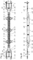
- FIG. 4 shows a view of the underframe 1 from FIG Fig. 2a of the page. It can be seen in this view that the longitudinal beam 5 defines a loading area 6 for the arrangement of containers and / or superstructures. It can also be seen that the longitudinal beam 5 comprises an upper belt 8 and a lower belt 9, which are arranged one above the other and are connected to one another and to the head pieces 2a, 2b at their ends via longitudinal webs 10a, 10b.
- the upper chord 8 and the lower chord 9 are essentially identical in construction.
- the upper chord 8 and the lower chord 9 are arranged one above the other at a distance which essentially corresponds to the width of the longitudinal beam 5 transversely to the central longitudinal axis 7, so that the longitudinal beam 5 has the shape of an essentially square hollow profile.
- the upper chord 8 and the lower chord 9 are selectively connected to one another via the K-shaped angled struts 22a, 22b.
- the angled struts 22a, 22b, 22c, 22d are K-shaped in such a way that two of their ends are connected to the upper chord 8 and the lower chord 9.
- the longitudinal webs 10a, 10b, 10c, 10d are Y-shaped, each with three longitudinal web ends 11a, 11b, 11c.
- One longitudinal web end 11a is connected to the upper chord 8
- a second longitudinal web end 11b is connected to the lower chord 9
- a third longitudinal web end 11c is connected to the head piece 2a, 2b.
- a non-weakened area 16a, 16b of the head piece 2a, 2b there is a rotating socket 17a, 17b on the underside.
- the transverse brackets 18, which are connected to both the upper chord 8 and the lower chord 9 and have container pins 20a, 20b on their upper side or in the area of the loading area 6 for receiving containers and / or superstructures.
- FIG. 2c shows a view of the underframe 1 according to the invention from above.
- the underframe 1 comprises two head pieces 2a, 2b, each with a buffer chest 3a, 3b and buffers 4 arranged thereon. Between the head pieces 2a, 2b, a longitudinal beam 5 extends symmetrically along a central longitudinal axis 7.
- the longitudinal beam 5 forms a loading area 6 for supporting containers and / or superstructures, the loading area 6 being formed by the surface of the upper belt 8.
- the head pieces 2a, 2b and the longitudinal beam 5 are designed essentially symmetrically to the central longitudinal axis 7.
- the head pieces 2a, 2b comprise several material recesses 13a, 13b, 13c separated from one another by material webs, which each extend from the area of the buffer chest 3a, 3b in the direction of the longitudinal member 5 and taper in this direction.
- the head pieces 2a, 2b themselves also taper from the area of the buffer breast 3a, 3b in the direction of the longitudinal member 5.
- at least two further material recesses 15a, 15b are provided, which also taper in this direction and are essentially triangular .
- the head pieces 2a, 2b taper from the area of the buffer breast 3a, 3b in the direction of the longitudinal beam 5 to about 40% of their extent transversely to the central longitudinal axis 7.
- the non-weakened area 16a, 16b each extends transversely to the central longitudinal axis 7.
- the head pieces 2a, 2b taper from the area of the buffer breast 3a, 3b in the direction of the longitudinal member 5 only from the non-weakened area 16a, 16b.
- the non-weakened areas 16a, 16b each extend along the central longitudinal axis 7 essentially over approximately 15% of the length of the head pieces 2a, 2b and slightly along the central longitudinal axis 7 in relation to the length of the head pieces 2a, 2b are provided offset in the direction of the longitudinal member 5.
- transverse brackets 18 with the container pins 20a, 20b arranged thereon.
- container pins 20a, 20b are only shown in the case of two transverse arms 18.
- the container pins 20a, 20b are used to hold containers and / or superstructures.
- the transverse arms 18 include supports 19a, 19b, which are arranged on the upper chord 8 and extend essentially transversely to the central longitudinal axis 7.
- cross struts 21a, 21b are provided which support the carrier 19a, 19b on the lower chord 9.
- Fig. 2d shows a further schematic view of the underframe 1 according to the invention along the line in FIG Figure 2c indicated section AA.
- the design of the longitudinal member 5 can be seen through the upper belt 8 and lower belt 9, which run parallel to one another and are connected to one another and to the head pieces 2a, 2b by the angled struts 22c, 22d and the longitudinal webs 10b, 10d.
- the longitudinal webs 10b, 10d are essentially Y-shaped and have three longitudinal web ends 11a, 11b, 11c.
- the first longitudinal web end 11a is connected to the upper flange 8, the second longitudinal web end 11b to the lower flange 9 and the third longitudinal web end 11c to the buffer breast 3a, 3b.
- longitudinal web ends 11a, 11b of the longitudinal webs 10a, 10b, 10c, 10d have stabilizing struts.
- material cutouts are also provided in the longitudinal webs 10a, 10b, 10c, 10d in order to reduce the weight of these elements.
- the rotary sockets 17a, 17b are in turn arranged in the non-weakened area 16a, 16b of the head pieces 2a, 2b.
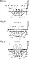
- Fig. 3a shows a schematic view of the underframe 1 according to the invention from the side, the buffers 4 and the buffer breast 3a being visible. Furthermore, the cross struts 21a, 21b for supporting the cross arms 18 are visible. Finally, it can be seen in this illustration that the longitudinal webs 10a, 10b run essentially parallel to the central longitudinal axis 7 of the longitudinal member 5. A lower part 23 is provided on the underside of the head piece 2a. The container pins 20a, 20b can also be seen in this illustration.
- Figure 3b shows the in Figure 2b indicated section BB in a schematic representation.
- the section runs transversely through the head piece 2a and the longitudinal webs 10a, 10b. Again, the cross struts 21a, 21b of the cross arm 18 can be seen.
- the lower part 23 can be seen on the underside of the head piece 2a.
- a shaped carrier profile 24a, 24b is arranged on the sides of the head piece 2a to increase the stability and to optimally introduce the buffer forces into the main cross member.
- Figure 3c shows a schematic representation of the in Figure 2b defined section CC, which runs in the region of the longitudinal member 5.
- the upper chord 8 and the lower chord 9 form an essentially square hollow profile.
- the loading area 6 defined by the upper side of the upper belt 8 and the transverse arm 18 with the transverse struts 21a, 21b.
- the lower part 23 arranged in the area of the head piece 2b can be seen.
- This lower part 23 also has material cutouts to reduce weight.
- the distance between the upper chord 8 and the lower chord 9 essentially corresponds to the width of the longitudinal member 5 transversely to the central longitudinal axis 7.
- the material reinforcements 12a, 12b, 12c, 12d of the upper chord 8 and the lower chord 9 can also be seen in this illustration.
- Figures 4a-4b show views of a longitudinal web 10a of an underframe according to the invention from the side and from above. It can be seen that the longitudinal web 10aY-shaped, each with three longitudinal web ends 11a, 11b, 11c. As in the top view according to Figure 4b is shown, the longitudinal web 10a is slightly curved in order to widen slightly in the direction from the longitudinal member to the head pieces. For this purpose, it is provided that the longitudinal web 10a is curved from the third longitudinal web end 11c in the direction of the first longitudinal web end 11a and the second longitudinal saw end 11b at an angle of approximately 5 °.
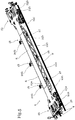
- Fig. 5 shows a schematic three-dimensional representation of a further embodiment of a platform trolley with a sub-frame 1 according to the invention Fig. 1 .
- the platform trolley comprises an underframe 1 with two head pieces 2a, 2b, each with a buffer breast 3a, 3b.
- Two buffers 4 are arranged on each buffer breast 3a, 3b.
- the two head pieces 2a, 2b are connected by a longitudinal beam 5 which defines a loading area 6 for supporting containers and / or superstructures.
- the longitudinal beam 5 extends along a central longitudinal axis 7 and has beams 19a, 19b for positioning the containers and / or superstructures.
- a shaped support profile 24a, 24b is arranged on the sides of the head pieces 2a, 2b.
- the longitudinal beam 5 comprises a one-piece upper chord 8 and a one-piece lower chord 9, which are arranged one above the other and at their ends are connected to one another and to the head pieces 2a, 2b via the longitudinal webs 10a, 10b.
- the upper chord 8 and the lower chord 9 are connected to one another via angle struts 22a, 22b.
- the two rotary pans 17a, 17b, which are each arranged on the underside of the head pieces 2a, 2b, are also shown.
- the width of the longitudinal member 5 transversely to the central longitudinal axis 7 is smaller than the width of the head pieces 2a, 2b transversely to the central longitudinal axis 7.
- the upper chord 8 and the lower chord 9 form an essentially box-shaped hollow body and act on the longitudinal member 5 via the carriers 19a, 19b Forces are efficiently diverted to the head pieces 2a, 2b via the longitudinal webs 10a, 10b.
- head pieces 2a, 2b have numerous recesses in order to reduce weight. It can also be seen that the upper chord 8 and the lower chord 9, in contrast to the embodiment of FIG Fig. 1 , are formed by essentially flat profile parts.
- FIG. 6a shows a schematic representation of an embodiment of a platform trolley according to the invention from below.
- the platform trolley comprises an underframe 1 with two head pieces 2a, 2b each with a buffer chest 3a, 3b for the arrangement of buffers 4.
- a longitudinal beam 5 with a central longitudinal axis 7 extends between the two head pieces 2a, 2b on the sides of the head pieces 2a, 2b a shaped support profile 24a, 24b is arranged in each case.
- the longitudinal member 5 comprises an upper belt 8 and a lower belt 9; In the illustrated view from below, only the lower chord 9 is visible.
- the upper chord 8 and the lower chord 9 are connected at their ends via longitudinal webs 10a, 10b, 10c, 10d to one another and to the head pieces 2a, 2b.
- the width of the longitudinal member 5 transversely to the central longitudinal axis 7 is smaller than the width of the head pieces 2a, 2b transversely to the central longitudinal axis 7, and in the present exemplary embodiment is about 40% of the width of the head pieces 2a, 2b transversely to the central longitudinal axis 7.
- Rotary sockets 17a, 17b are arranged on the underside of the head pieces 2a, 2b. These are located in a non-weakened area 16a, 16b of the two head pieces 2a, 2b.
- Each of the two head pieces 2a, 2b is connected to the upper chord 8 and the lower chord 9 via two separate longitudinal webs 10a, 10b and 10c, 10d, the longitudinal webs 10a, 10b, 10c, 10d running essentially parallel to one another and essentially normal to loading area 6, not shown, are arranged.
- the longitudinal webs 10a, 10b, 10c, 10d are slightly curved in relation to the central longitudinal axis 7. Both the head pieces 2a, 2b and the longitudinal member 5 are designed essentially symmetrically to the central longitudinal axis 7.
- the head pieces 2a, 2b taper from the area of the buffer breast 3a, 3b in the direction of the longitudinal beam 5.
- the taper is about 40% of its extent transverse to the central longitudinal axis 7, in other words the extent of the Head pieces 2a, 2b in the area of the transition to the longitudinal beam 5 are only 40% of their extent in the area of the buffer chest 3a, 3b.
- the tapering begins, however, only after the non-weakened area 16a, 16b.
- the head pieces 2a, 2b thus taper from the area of the buffer chest 3a, 3b in the direction of the longitudinal member 5 only from the non-weakened area 16a, 16b, so that the full width of the head pieces 2a, 2b is available for the rotary sockets 17a, 17b.
- the transverse arms 18 are arranged on the upper chord 8 and are supported on the lower chord 9 via cross struts 21a, 21b.
- FIG. 6b shows a view of the underframe 1 according to the invention from above.
- the underframe 1 comprises two head pieces 2a, 2b, each with a buffer chest 3a, 3b and buffers 4 arranged thereon. Between the head pieces 2a, 2b, a longitudinal beam 5 extends symmetrically along a central longitudinal axis 7.
- the longitudinal beam 5 forms a loading area 6 for supporting containers and / or superstructures, the loading area 6 being formed by the surface of the upper belt 8.
- the head pieces 2a, 2b and the longitudinal beam 5 are designed essentially symmetrically to the central longitudinal axis 7.
- the head pieces 2a, 2b comprise several material recesses 13a, 13b, 13c separated from one another by material webs, which each extend from the area of the buffer chest 3a, 3b in the direction of the longitudinal member 5 and taper in this direction.
- the head pieces 2a, 2b themselves also taper from the area of the buffer breast 3a, 3b in the direction of the longitudinal member 5.
- at least two further material recesses 15a, 15b are provided, which also taper in this direction and are essentially triangular .
- the head pieces 2a, 2b taper from the area of the buffer breast 3a, 3b in the direction of the longitudinal beam 5 to about 40% of their extent transversely to the central longitudinal axis 7.
- the non-weakened area 16a, 16b each extends transversely to the central longitudinal axis 7.
- the head pieces 2a, 2b taper from the area of the buffer breast 3a, 3b in the direction of the longitudinal member 5 only from the non-weakened area 16a, 16b.
- the non-weakened areas 16a, 16b each extend along the central longitudinal axis 7 essentially over approximately 15% of the length of the head pieces 2a, 2b and slightly along the central longitudinal axis 7 in relation to the length of the head pieces 2a, 2b are provided offset in the direction of the longitudinal member 5.
- transverse brackets 18 with the container pins 20a, 20b arranged thereon.
- the container pins 20a, 20b are used to hold containers and / or superstructures.
- the transverse arms 18 include supports 19a, 19b, which are arranged on the upper chord 8 and extend essentially transversely to the central longitudinal axis 7.
- cross struts 21a, 21b are provided which support the carrier 19a, 19b on the lower chord 9.
- Figure 6c shows a view of the underframe 1 from the side. It can be seen in this view that the longitudinal beam 5 defines a loading area 6 for the arrangement of containers and / or superstructures. It can also be seen that the longitudinal beam 5 comprises an upper belt 8 and a lower belt 9, which are arranged one above the other and are connected to one another and to the head pieces 2a, 2b at their ends via longitudinal webs 10a, 10b.
- the upper chord 8 and the lower chord 9 are essentially identical in construction.
- the upper chord 8 and the lower chord 9 are arranged one above the other at a distance which essentially corresponds to the width of the longitudinal beam 5 transversely to the central longitudinal axis 7, so that the longitudinal beam 5 has the shape of an essentially square hollow profile.
- the upper chord 8 and the lower chord 9 are selectively connected to one another via the angled struts 22a, 22b, 22c, 22d.
- the longitudinal webs 10a, 10b, 10c, 10d are Y-shaped, each with three longitudinal web ends 11a, 11b, 11c.
- One longitudinal web end 11a is connected to the upper chord 8
- a second longitudinal web end 11b is connected to the lower chord 9
- a third longitudinal web end 11c is connected to the head piece 2a, 2b.
- the ends of the longitudinal webs are connected to one another via struts.
- transverse brackets 18 which are connected to both the upper chord 8 and the lower chord 9 and have container pins 20a, 20b on their upper side or in the area of the loading area 6 for receiving containers and / or superstructures.
- Fig. 6d shows a schematic view of the underframe 1 according to the invention from the side, the buffers 4 and the buffer breast 3a being visible. Furthermore, the cross struts 21a, 21b for supporting the cross arms 18 are visible. Finally, it can be seen in this illustration that the longitudinal webs 10a, 10b run essentially parallel to the central longitudinal axis 7 of the longitudinal member 5. A lower part 23 is provided on the underside of the head piece 2a. The container pins 20a, 20b can also be seen in this illustration.
- Figure 6e shows the in Figure 6c indicated section BB in a schematic representation.
- the section runs transversely through the head piece 2a and the longitudinal webs 10a, 10b. Again, the cross struts 21a, 21b of the cross arm 18 can be seen.
- the lower part 23 can be seen on the underside of the head piece 2a.
- a shaped carrier profile 24a, 24b is arranged on the sides of the head piece 2a to increase the stability and to optimally introduce the buffer forces into the main cross member.
- Fig. 6f shows a schematic representation of the in Figure 6c defined section CC, which runs in the region of the longitudinal member 5.
- the upper chord 8 and the lower chord 9 form an essentially square hollow profile.
- the loading area 6 defined by the upper side of the upper belt 8 and the transverse arm 18 with the transverse struts 21a, 21b.
- the lower part 23 arranged in the area of the head piece 2b can be seen.
- This lower part 23 also has material cutouts to reduce weight.
- the distance between the upper chord 8 and the lower chord 9 essentially corresponds to the width of the longitudinal member 5 transversely to the central longitudinal axis 7.
- the stiffening ribs 26a, 26b of the upper chord 8 can also be seen in this illustration.
- the two stiffening ribs 26a, 26b are arranged on the underside of the upper belt 8 and run parallel to one another along the central longitudinal axis 7 and extend downward normal to the loading area 6.
- Figures 7a-7b show views of a longitudinal web 10a of an underframe according to the invention from the side and from above. It can be seen that the longitudinal web 10a is Y-shaped, each with three longitudinal web ends 11a, 11b, 11c. To increase the stability, the first longitudinal web end 11a is connected to the second longitudinal web end 11b via material struts.
- the longitudinal web 10a is slightly curved in order to widen slightly in the direction from the longitudinal member to the head pieces.
- the longitudinal web 10a is curved from the third longitudinal web end 11c in the direction of the first longitudinal web end 11a and the second longitudinal saw end 11b at an angle of approximately 5 °.
- the underframe in question was the result of a cooperation between Rail Cargo Wagon - Austria GmbH and the voestalpine Group, in particular the voestalpine Steel Division and the voestalpine Metal Forming Division.
Landscapes
- Engineering & Computer Science (AREA)
- Mechanical Engineering (AREA)
- Vibration Dampers (AREA)
- Body Structure For Vehicles (AREA)
- Refuge Islands, Traffic Blockers, Or Guard Fence (AREA)
- Platform Screen Doors And Railroad Systems (AREA)
- Devices Affording Protection Of Roads Or Walls For Sound Insulation (AREA)
Priority Applications (2)
| Application Number | Priority Date | Filing Date | Title |
|---|---|---|---|
| SI201830404T SI3630573T1 (sl) | 2017-05-31 | 2018-05-29 | Podvozje za voziček |
| PL18728128T PL3630573T3 (pl) | 2017-05-31 | 2018-05-29 | Podwozie do wózka platformowego |
Applications Claiming Priority (2)
| Application Number | Priority Date | Filing Date | Title |
|---|---|---|---|
| ATA50453/2017A AT520110B1 (de) | 2017-05-31 | 2017-05-31 | Untergestell für einen Plattformwagen |
| PCT/EP2018/064078 WO2018219955A1 (de) | 2017-05-31 | 2018-05-29 | Untergestell für einen plattformwagen |
Publications (2)
| Publication Number | Publication Date |
|---|---|
| EP3630573A1 EP3630573A1 (de) | 2020-04-08 |
| EP3630573B1 true EP3630573B1 (de) | 2021-06-23 |
Family
ID=62455494
Family Applications (1)
| Application Number | Title | Priority Date | Filing Date |
|---|---|---|---|
| EP18728128.2A Active EP3630573B1 (de) | 2017-05-31 | 2018-05-29 | Untergestell für einen plattformwagen |
Country Status (8)
| Country | Link |
|---|---|
| EP (1) | EP3630573B1 (zh) |
| CN (1) | CN111032474B (zh) |
| AT (1) | AT520110B1 (zh) |
| HU (1) | HUE055723T2 (zh) |
| PL (1) | PL3630573T3 (zh) |
| RU (1) | RU2759684C2 (zh) |
| SI (1) | SI3630573T1 (zh) |
| WO (1) | WO2018219955A1 (zh) |
Families Citing this family (9)
| Publication number | Priority date | Publication date | Assignee | Title |
|---|---|---|---|---|
| AT520110B1 (de) | 2017-05-31 | 2019-08-15 | Rail Cargo Wagon Austria Gmbh | Untergestell für einen Plattformwagen |
| DE102019105689B3 (de) | 2019-03-06 | 2020-06-04 | Deutsche Bahn Ag | Untergestell eines Schienenfahrzeuges |
| DE102019105686B3 (de) | 2019-03-06 | 2020-04-16 | Deutsche Bahn Ag | Untergestell eines Schienenfahrzeuges |
| EP3708453B1 (de) * | 2019-03-15 | 2022-10-12 | Schweizerische Bundesbahnen SBB | Untergestell für fahrzeuge und fahrzeug |
| DE102020119526A1 (de) | 2020-07-23 | 2022-01-27 | Deutsche Bahn Aktiengesellschaft | Untergestell eines schienenfahrzeuges |
| DE102020134258A1 (de) | 2020-12-18 | 2022-06-23 | Deutsche Bahn Aktiengesellschaft | Untergestell eines schienenfahrzeuges |
| CN115123330A (zh) * | 2021-03-24 | 2022-09-30 | 中车山东机车车辆有限公司 | 车体底架及车辆 |
| FR3138640A1 (fr) * | 2022-08-05 | 2024-02-09 | Cgl | Structure de wagon pour le transport de conteneurs |
| EP4316940A1 (fr) * | 2022-08-05 | 2024-02-07 | Cgl | Structure de wagon pour le transport de conteneurs |
Citations (17)
| Publication number | Priority date | Publication date | Assignee | Title |
|---|---|---|---|---|
| US1038753A (en) | 1911-06-16 | 1912-09-17 | Locomotive Tender Frame Company | Cast-steel underframe for cars. |
| US1078312A (en) | 1912-11-19 | 1913-11-11 | American Car & Foundry Co | Cast end frame. |
| US1097800A (en) | 1912-09-12 | 1914-05-26 | Bettendorf Co | Underframe for cars. |
| US1659361A (en) | 1927-01-12 | 1928-02-14 | Ohio Steel Foundry Co | Cast-steel tender frame |
| NL6613028A (zh) | 1965-11-06 | 1967-05-08 | ||
| DE1919179A1 (de) | 1969-04-16 | 1970-10-22 | Rheinstahl Siegener Eisenbahnb | Untergestell fuer Schienenfahrzeuge |
| DE2903249A1 (de) | 1979-01-29 | 1980-08-07 | Ringfeder Gmbh | Kopftraeger fuer seitenpuffer, insbesondere fuer schienenfahrzeuge |
| GB2283219A (en) | 1993-10-27 | 1995-05-03 | Transtech Ltd Oy | A railway car for transporting trailers. |
| DE4440425A1 (de) | 1994-11-07 | 1996-05-09 | Goerlitz Waggonbau Gmbh | Untergestell für Schienenfahrzeuge |
| DE19805429A1 (de) | 1998-02-11 | 1999-08-12 | Elze Waggonbau Gmbh & Co Kg | Behältertragwagen zum Transport von Containern oder Wechselbehältern auf dem Eisenbahnnetz |
| DE60009038T2 (de) | 1999-12-10 | 2004-11-18 | Arbel Fauvet Rail S.A. | Drehgestell zur nutzung bei eisenbahnen und waggon mit solch einem drehgestell |
| CN102079314A (zh) | 2010-12-23 | 2011-06-01 | 南车二七车辆有限公司 | 一种适应泰国米轨铁路运行的增载型集装箱平车车体 |
| CN104057968A (zh) | 2014-06-25 | 2014-09-24 | 齐齐哈尔轨道交通装备有限责任公司 | 一种集装箱平车的车架 |
| EP2837542A1 (de) | 2013-08-14 | 2015-02-18 | Peter Wanek-Pusset | Wagenrahmen für einen Containertragwagen und Containertragwagen |
| CN105460037A (zh) | 2015-12-25 | 2016-04-06 | 中车长江车辆有限公司 | 一种平车车体 |
| DE202016104134U1 (de) | 2016-07-27 | 2016-09-19 | Wbn Waggonbau Niesky Gmbh | Untergestell eines Schienenfahrzeuges |
| WO2018219955A1 (de) | 2017-05-31 | 2018-12-06 | Rail Cargo Wagon - Austria Gmbh | Untergestell für einen plattformwagen |
Family Cites Families (11)
| Publication number | Priority date | Publication date | Assignee | Title |
|---|---|---|---|---|
| US1078310A (en) * | 1912-08-14 | 1913-11-11 | American Car & Foundry Co | Underframe. |
| DE1233002B (de) * | 1960-12-08 | 1967-01-26 | Pullman Inc | Auf der Ladeflaeche eines Eisenbahnplattformwagens anbringbarer Frachtbehaelter-Traegerrahmen |
| AT394531B (de) * | 1990-01-19 | 1992-04-27 | Jenbacher Werke Ag | Schienenfahrzeug, insbesondere zweiachsiger gueterwagen |
| CN1189426A (zh) * | 1997-01-28 | 1998-08-05 | 约翰斯汤美国公司 | 具有料桶的铁路敞车 |
| RU96080U1 (ru) * | 2009-08-07 | 2010-07-20 | ОАО "Завод металлоконструкций" | Железнодорожная платформа для перевозки крупнотоннажных контейнеров |
| CN201907519U (zh) * | 2011-01-10 | 2011-07-27 | 南车株洲电力机车有限公司 | 一种中低速磁浮列车悬浮架纵梁 |
| RU108014U1 (ru) * | 2011-03-28 | 2011-09-10 | Афст Эдвансд Фрайт Кар Текнолоджи Лимитед | Рама вагона-платформы |
| DE102012102808A1 (de) * | 2012-03-30 | 2013-10-02 | Demag Cranes & Components Gmbh | Kran, insbesondere Brückenkran oder Portalkran, mit mindestens einem Kranträger |
| JP5931548B2 (ja) * | 2012-04-02 | 2016-06-08 | 川崎重工業株式会社 | 鉄道車両 |
| CN104670252A (zh) * | 2013-12-01 | 2015-06-03 | 太原轨道交通装备有限责任公司 | 低重心集装箱平车 |
| CN204055786U (zh) * | 2014-07-23 | 2014-12-31 | 南车眉山车辆有限公司 | 一种铁路集装箱专用平车 |
-
2017
- 2017-05-31 AT ATA50453/2017A patent/AT520110B1/de active
-
2018
- 2018-05-29 SI SI201830404T patent/SI3630573T1/sl unknown
- 2018-05-29 CN CN201880036686.6A patent/CN111032474B/zh active Active
- 2018-05-29 RU RU2019143707A patent/RU2759684C2/ru active
- 2018-05-29 HU HUE18728128A patent/HUE055723T2/hu unknown
- 2018-05-29 PL PL18728128T patent/PL3630573T3/pl unknown
- 2018-05-29 EP EP18728128.2A patent/EP3630573B1/de active Active
- 2018-05-29 WO PCT/EP2018/064078 patent/WO2018219955A1/de active Application Filing
Patent Citations (17)
| Publication number | Priority date | Publication date | Assignee | Title |
|---|---|---|---|---|
| US1038753A (en) | 1911-06-16 | 1912-09-17 | Locomotive Tender Frame Company | Cast-steel underframe for cars. |
| US1097800A (en) | 1912-09-12 | 1914-05-26 | Bettendorf Co | Underframe for cars. |
| US1078312A (en) | 1912-11-19 | 1913-11-11 | American Car & Foundry Co | Cast end frame. |
| US1659361A (en) | 1927-01-12 | 1928-02-14 | Ohio Steel Foundry Co | Cast-steel tender frame |
| NL6613028A (zh) | 1965-11-06 | 1967-05-08 | ||
| DE1919179A1 (de) | 1969-04-16 | 1970-10-22 | Rheinstahl Siegener Eisenbahnb | Untergestell fuer Schienenfahrzeuge |
| DE2903249A1 (de) | 1979-01-29 | 1980-08-07 | Ringfeder Gmbh | Kopftraeger fuer seitenpuffer, insbesondere fuer schienenfahrzeuge |
| GB2283219A (en) | 1993-10-27 | 1995-05-03 | Transtech Ltd Oy | A railway car for transporting trailers. |
| DE4440425A1 (de) | 1994-11-07 | 1996-05-09 | Goerlitz Waggonbau Gmbh | Untergestell für Schienenfahrzeuge |
| DE19805429A1 (de) | 1998-02-11 | 1999-08-12 | Elze Waggonbau Gmbh & Co Kg | Behältertragwagen zum Transport von Containern oder Wechselbehältern auf dem Eisenbahnnetz |
| DE60009038T2 (de) | 1999-12-10 | 2004-11-18 | Arbel Fauvet Rail S.A. | Drehgestell zur nutzung bei eisenbahnen und waggon mit solch einem drehgestell |
| CN102079314A (zh) | 2010-12-23 | 2011-06-01 | 南车二七车辆有限公司 | 一种适应泰国米轨铁路运行的增载型集装箱平车车体 |
| EP2837542A1 (de) | 2013-08-14 | 2015-02-18 | Peter Wanek-Pusset | Wagenrahmen für einen Containertragwagen und Containertragwagen |
| CN104057968A (zh) | 2014-06-25 | 2014-09-24 | 齐齐哈尔轨道交通装备有限责任公司 | 一种集装箱平车的车架 |
| CN105460037A (zh) | 2015-12-25 | 2016-04-06 | 中车长江车辆有限公司 | 一种平车车体 |
| DE202016104134U1 (de) | 2016-07-27 | 2016-09-19 | Wbn Waggonbau Niesky Gmbh | Untergestell eines Schienenfahrzeuges |
| WO2018219955A1 (de) | 2017-05-31 | 2018-12-06 | Rail Cargo Wagon - Austria Gmbh | Untergestell für einen plattformwagen |
Non-Patent Citations (2)
| Title |
|---|
| "Ecofret- a new kind container wagon", ON-LINE THE NEWSLETTER OF VTG RAIL UK LTD, 2011, XP055908464 |
| ANONYMOUS: "Gurt (BAUTEIL)", WIKIPEDIA, 7 December 2021 (2021-12-07), XP055908932, [retrieved on 20220405] |
Also Published As
| Publication number | Publication date |
|---|---|
| CN111032474B (zh) | 2022-03-25 |
| CN111032474A (zh) | 2020-04-17 |
| RU2759684C2 (ru) | 2021-11-16 |
| SI3630573T1 (sl) | 2021-11-30 |
| PL3630573T3 (pl) | 2021-12-20 |
| AT520110A1 (de) | 2019-01-15 |
| RU2019143707A3 (zh) | 2021-09-08 |
| HUE055723T2 (hu) | 2021-12-28 |
| RU2019143707A (ru) | 2021-06-30 |
| EP3630573A1 (de) | 2020-04-08 |
| WO2018219955A1 (de) | 2018-12-06 |
| AT520110B1 (de) | 2019-08-15 |
Similar Documents
| Publication | Publication Date | Title |
|---|---|---|
| EP3630573B1 (de) | Untergestell für einen plattformwagen | |
| DE4208700C2 (de) | Vorbaukonstruktion für Fahrzeuge | |
| DE102010014302B4 (de) | Luftfahrzeug und Befestigungsanordnung für eine Fußbodenstruktur in einem Luftfahrzeug | |
| DE2702243C2 (zh) | ||
| EP1832491A2 (de) | Schienenfahrzeug mit einem Untergestell | |
| EP3114011B1 (de) | Versteifungsstruktur eines fahrzeugs in form eines schubfelds | |
| EP3696056B1 (de) | Fahrzeug-chassis-modul mit fahrzeug-achse und anschlussknoten | |
| EP2390164B1 (de) | Fahrzeugkarrosserieaufbau im Fersenblechbereich einer Insassenkabine | |
| AT515824A1 (de) | Kranträger für einen Kran | |
| EP3093220B1 (de) | Expandierbarer fahrzeuganhänger | |
| EP3699058B1 (de) | Anordnung aus schienenfahrzeug und tragvorrichtung | |
| DE10126234B4 (de) | Aufbaustruktur für ein Kraftfahrzeug mit zusammengesetzten Trägern | |
| DE102005045295B4 (de) | Fahrschemel für ein Kraftfahrzeug | |
| WO2021156780A1 (de) | Untergestell für plattformwagen sowie plattformwagen | |
| DE102019105689B3 (de) | Untergestell eines Schienenfahrzeuges | |
| DE19750981C2 (de) | Rahmen für Kraftfahrzeuge | |
| DE102014223054B4 (de) | Fahrzeugkarosserie für ein zweispuriges Fahrzeug | |
| EP1692034A1 (de) | A-säule für ein kraftfahrzeug | |
| EP2766245B1 (de) | Hilfsrahmen für kraftfahrzeuge | |
| EP0111824B1 (de) | Absetzkipper-Aufbau für Lastwagen | |
| DE2350565B2 (de) | Schienenfahrzeug, insbesondere gedeckter, grossraeumiger gueterwagen mit verschiebbaren wandteilen | |
| EP4038008B1 (de) | Träger für eine laufkatze und flurfreie transporteinrichtung mit einem solchen träger | |
| EP2671776B1 (de) | Tragbock für eine einen Querträger umfassende Tragkonstruktion für ein Kraftfahrzeug | |
| DE975378C (de) | Niederrahmen fuer Kraftfahrzeuge, insbesondere Kraftomnibusse | |
| DE3403764A1 (de) | Versteifung fuer eine zu einem kabriolett umgebaute limousine |
Legal Events
| Date | Code | Title | Description |
|---|---|---|---|
| STAA | Information on the status of an ep patent application or granted ep patent |
Free format text: STATUS: UNKNOWN |
|
| STAA | Information on the status of an ep patent application or granted ep patent |
Free format text: STATUS: THE INTERNATIONAL PUBLICATION HAS BEEN MADE |
|
| PUAI | Public reference made under article 153(3) epc to a published international application that has entered the european phase |
Free format text: ORIGINAL CODE: 0009012 |
|
| STAA | Information on the status of an ep patent application or granted ep patent |
Free format text: STATUS: REQUEST FOR EXAMINATION WAS MADE |
|
| 17P | Request for examination filed |
Effective date: 20191126 |
|
| AK | Designated contracting states |
Kind code of ref document: A1 Designated state(s): AL AT BE BG CH CY CZ DE DK EE ES FI FR GB GR HR HU IE IS IT LI LT LU LV MC MK MT NL NO PL PT RO RS SE SI SK SM TR |
|
| AX | Request for extension of the european patent |
Extension state: BA ME |
|
| DAV | Request for validation of the european patent (deleted) | ||
| DAX | Request for extension of the european patent (deleted) | ||
| GRAP | Despatch of communication of intention to grant a patent |
Free format text: ORIGINAL CODE: EPIDOSNIGR1 |
|
| STAA | Information on the status of an ep patent application or granted ep patent |
Free format text: STATUS: GRANT OF PATENT IS INTENDED |
|
| INTG | Intention to grant announced |
Effective date: 20210122 |
|
| GRAS | Grant fee paid |
Free format text: ORIGINAL CODE: EPIDOSNIGR3 |
|
| GRAA | (expected) grant |
Free format text: ORIGINAL CODE: 0009210 |
|
| STAA | Information on the status of an ep patent application or granted ep patent |
Free format text: STATUS: THE PATENT HAS BEEN GRANTED |
|
| AK | Designated contracting states |
Kind code of ref document: B1 Designated state(s): AL AT BE BG CH CY CZ DE DK EE ES FI FR GB GR HR HU IE IS IT LI LT LU LV MC MK MT NL NO PL PT RO RS SE SI SK SM TR |
|
| REG | Reference to a national code |
Ref country code: GB Ref legal event code: FG4D Free format text: NOT ENGLISH |
|
| REG | Reference to a national code |
Ref country code: CH Ref legal event code: EP |
|
| REG | Reference to a national code |
Ref country code: DE Ref legal event code: R096 Ref document number: 502018005832 Country of ref document: DE Ref country code: AT Ref legal event code: REF Ref document number: 1404069 Country of ref document: AT Kind code of ref document: T Effective date: 20210715 |
|
| REG | Reference to a national code |
Ref country code: IE Ref legal event code: FG4D Free format text: LANGUAGE OF EP DOCUMENT: GERMAN |
|
| REG | Reference to a national code |
Ref country code: SE Ref legal event code: TRGR |
|
| REG | Reference to a national code |
Ref country code: RO Ref legal event code: EPE |
|
| REG | Reference to a national code |
Ref country code: LT Ref legal event code: MG9D |
|
| REG | Reference to a national code |
Ref country code: SK Ref legal event code: T3 Ref document number: E 38043 Country of ref document: SK |
|
| PG25 | Lapsed in a contracting state [announced via postgrant information from national office to epo] |
Ref country code: HR Free format text: LAPSE BECAUSE OF FAILURE TO SUBMIT A TRANSLATION OF THE DESCRIPTION OR TO PAY THE FEE WITHIN THE PRESCRIBED TIME-LIMIT Effective date: 20210623 Ref country code: LT Free format text: LAPSE BECAUSE OF FAILURE TO SUBMIT A TRANSLATION OF THE DESCRIPTION OR TO PAY THE FEE WITHIN THE PRESCRIBED TIME-LIMIT Effective date: 20210623 Ref country code: FI Free format text: LAPSE BECAUSE OF FAILURE TO SUBMIT A TRANSLATION OF THE DESCRIPTION OR TO PAY THE FEE WITHIN THE PRESCRIBED TIME-LIMIT Effective date: 20210623 |
|
| PG25 | Lapsed in a contracting state [announced via postgrant information from national office to epo] |
Ref country code: RS Free format text: LAPSE BECAUSE OF FAILURE TO SUBMIT A TRANSLATION OF THE DESCRIPTION OR TO PAY THE FEE WITHIN THE PRESCRIBED TIME-LIMIT Effective date: 20210623 Ref country code: NO Free format text: LAPSE BECAUSE OF FAILURE TO SUBMIT A TRANSLATION OF THE DESCRIPTION OR TO PAY THE FEE WITHIN THE PRESCRIBED TIME-LIMIT Effective date: 20210923 Ref country code: LV Free format text: LAPSE BECAUSE OF FAILURE TO SUBMIT A TRANSLATION OF THE DESCRIPTION OR TO PAY THE FEE WITHIN THE PRESCRIBED TIME-LIMIT Effective date: 20210623 Ref country code: GR Free format text: LAPSE BECAUSE OF FAILURE TO SUBMIT A TRANSLATION OF THE DESCRIPTION OR TO PAY THE FEE WITHIN THE PRESCRIBED TIME-LIMIT Effective date: 20210924 |
|
| REG | Reference to a national code |
Ref country code: NL Ref legal event code: MP Effective date: 20210623 |
|
| REG | Reference to a national code |
Ref country code: HU Ref legal event code: AG4A Ref document number: E055723 Country of ref document: HU |
|
| PG25 | Lapsed in a contracting state [announced via postgrant information from national office to epo] |
Ref country code: EE Free format text: LAPSE BECAUSE OF FAILURE TO SUBMIT A TRANSLATION OF THE DESCRIPTION OR TO PAY THE FEE WITHIN THE PRESCRIBED TIME-LIMIT Effective date: 20210623 Ref country code: ES Free format text: LAPSE BECAUSE OF FAILURE TO SUBMIT A TRANSLATION OF THE DESCRIPTION OR TO PAY THE FEE WITHIN THE PRESCRIBED TIME-LIMIT Effective date: 20210623 Ref country code: SM Free format text: LAPSE BECAUSE OF FAILURE TO SUBMIT A TRANSLATION OF THE DESCRIPTION OR TO PAY THE FEE WITHIN THE PRESCRIBED TIME-LIMIT Effective date: 20210623 Ref country code: PT Free format text: LAPSE BECAUSE OF FAILURE TO SUBMIT A TRANSLATION OF THE DESCRIPTION OR TO PAY THE FEE WITHIN THE PRESCRIBED TIME-LIMIT Effective date: 20211025 Ref country code: NL Free format text: LAPSE BECAUSE OF FAILURE TO SUBMIT A TRANSLATION OF THE DESCRIPTION OR TO PAY THE FEE WITHIN THE PRESCRIBED TIME-LIMIT Effective date: 20210623 |
|
| REG | Reference to a national code |
Ref country code: DE Ref legal event code: R026 Ref document number: 502018005832 Country of ref document: DE |
|
| PLBI | Opposition filed |
Free format text: ORIGINAL CODE: 0009260 |
|
| PLAX | Notice of opposition and request to file observation + time limit sent |
Free format text: ORIGINAL CODE: EPIDOSNOBS2 |
|
| 26 | Opposition filed |
Opponent name: VTG RAIL EUROPE GMBH Effective date: 20220323 Opponent name: DEUTSCHE BAHN AG Effective date: 20220321 |
|
| PG25 | Lapsed in a contracting state [announced via postgrant information from national office to epo] |
Ref country code: DK Free format text: LAPSE BECAUSE OF FAILURE TO SUBMIT A TRANSLATION OF THE DESCRIPTION OR TO PAY THE FEE WITHIN THE PRESCRIBED TIME-LIMIT Effective date: 20210623 |
|
| PG25 | Lapsed in a contracting state [announced via postgrant information from national office to epo] |
Ref country code: AL Free format text: LAPSE BECAUSE OF FAILURE TO SUBMIT A TRANSLATION OF THE DESCRIPTION OR TO PAY THE FEE WITHIN THE PRESCRIBED TIME-LIMIT Effective date: 20210623 |
|
| PLBB | Reply of patent proprietor to notice(s) of opposition received |
Free format text: ORIGINAL CODE: EPIDOSNOBS3 |
|
| REG | Reference to a national code |
Ref country code: BE Ref legal event code: MM Effective date: 20220531 |
|
| GBPC | Gb: european patent ceased through non-payment of renewal fee |
Effective date: 20220529 |
|
| PG25 | Lapsed in a contracting state [announced via postgrant information from national office to epo] |
Ref country code: MC Free format text: LAPSE BECAUSE OF FAILURE TO SUBMIT A TRANSLATION OF THE DESCRIPTION OR TO PAY THE FEE WITHIN THE PRESCRIBED TIME-LIMIT Effective date: 20210623 Ref country code: LU Free format text: LAPSE BECAUSE OF NON-PAYMENT OF DUE FEES Effective date: 20220529 |
|
| PG25 | Lapsed in a contracting state [announced via postgrant information from national office to epo] |
Ref country code: IE Free format text: LAPSE BECAUSE OF NON-PAYMENT OF DUE FEES Effective date: 20220529 |
|
| PGFP | Annual fee paid to national office [announced via postgrant information from national office to epo] |
Ref country code: RO Payment date: 20230315 Year of fee payment: 6 |
|
| PG25 | Lapsed in a contracting state [announced via postgrant information from national office to epo] |
Ref country code: GB Free format text: LAPSE BECAUSE OF NON-PAYMENT OF DUE FEES Effective date: 20220529 Ref country code: BE Free format text: LAPSE BECAUSE OF NON-PAYMENT OF DUE FEES Effective date: 20220531 |
|
| P01 | Opt-out of the competence of the unified patent court (upc) registered |
Effective date: 20230516 |
|
| PGFP | Annual fee paid to national office [announced via postgrant information from national office to epo] |
Ref country code: IT Payment date: 20230526 Year of fee payment: 6 Ref country code: FR Payment date: 20230526 Year of fee payment: 6 Ref country code: DE Payment date: 20230503 Year of fee payment: 6 Ref country code: CZ Payment date: 20230523 Year of fee payment: 6 Ref country code: CH Payment date: 20230602 Year of fee payment: 6 Ref country code: BG Payment date: 20230526 Year of fee payment: 6 |
|
| PGFP | Annual fee paid to national office [announced via postgrant information from national office to epo] |
Ref country code: TR Payment date: 20230526 Year of fee payment: 6 Ref country code: SK Payment date: 20230522 Year of fee payment: 6 Ref country code: SI Payment date: 20230519 Year of fee payment: 6 Ref country code: SE Payment date: 20230519 Year of fee payment: 6 Ref country code: PL Payment date: 20230426 Year of fee payment: 6 Ref country code: HU Payment date: 20230523 Year of fee payment: 6 Ref country code: AT Payment date: 20230502 Year of fee payment: 6 |
|
| PG25 | Lapsed in a contracting state [announced via postgrant information from national office to epo] |
Ref country code: MK Free format text: LAPSE BECAUSE OF FAILURE TO SUBMIT A TRANSLATION OF THE DESCRIPTION OR TO PAY THE FEE WITHIN THE PRESCRIBED TIME-LIMIT Effective date: 20210623 Ref country code: CY Free format text: LAPSE BECAUSE OF FAILURE TO SUBMIT A TRANSLATION OF THE DESCRIPTION OR TO PAY THE FEE WITHIN THE PRESCRIBED TIME-LIMIT Effective date: 20210623 |