EP3621186B1 - Reinigungsvorrichutng und verfahren zum reinigen eines im tauchverfahren beschichteten körpers - Google Patents
Reinigungsvorrichutng und verfahren zum reinigen eines im tauchverfahren beschichteten körpers Download PDFInfo
- Publication number
- EP3621186B1 EP3621186B1 EP19186208.5A EP19186208A EP3621186B1 EP 3621186 B1 EP3621186 B1 EP 3621186B1 EP 19186208 A EP19186208 A EP 19186208A EP 3621186 B1 EP3621186 B1 EP 3621186B1
- Authority
- EP
- European Patent Office
- Prior art keywords
- coating fluid
- cleaning device
- functional surface
- cleaning
- winding material
- Prior art date
- Legal status (The legal status is an assumption and is not a legal conclusion. Google has not performed a legal analysis and makes no representation as to the accuracy of the status listed.)
- Active
Links
- 238000004140 cleaning Methods 0.000 title claims description 74
- 238000000034 method Methods 0.000 title claims description 17
- 239000011248 coating agent Substances 0.000 claims description 78
- 239000012530 fluid Substances 0.000 claims description 77
- 238000000576 coating method Methods 0.000 claims description 76
- 239000000463 material Substances 0.000 claims description 44
- 238000004804 winding Methods 0.000 claims description 29
- 238000007654 immersion Methods 0.000 claims description 8
- 230000002745 absorbent Effects 0.000 claims description 3
- 239000002250 absorbent Substances 0.000 claims description 3
- 238000007598 dipping method Methods 0.000 claims description 3
- 238000001125 extrusion Methods 0.000 description 7
- 239000007788 liquid Substances 0.000 description 6
- 210000001331 nose Anatomy 0.000 description 4
- 238000004519 manufacturing process Methods 0.000 description 3
- 239000000443 aerosol Substances 0.000 description 2
- 239000013013 elastic material Substances 0.000 description 2
- 238000005470 impregnation Methods 0.000 description 2
- 239000002184 metal Substances 0.000 description 2
- 238000011109 contamination Methods 0.000 description 1
- 230000009189 diving Effects 0.000 description 1
- 229920001971 elastomer Polymers 0.000 description 1
- 239000000806 elastomer Substances 0.000 description 1
- 230000002427 irreversible effect Effects 0.000 description 1
- 238000012958 reprocessing Methods 0.000 description 1
- 125000006850 spacer group Chemical group 0.000 description 1
- 238000003860 storage Methods 0.000 description 1
- 238000004381 surface treatment Methods 0.000 description 1
- 230000007704 transition Effects 0.000 description 1
Images


Classifications
-
- B08B1/143—
-
- H—ELECTRICITY
- H02—GENERATION; CONVERSION OR DISTRIBUTION OF ELECTRIC POWER
- H02K—DYNAMO-ELECTRIC MACHINES
- H02K15/00—Methods or apparatus specially adapted for manufacturing, assembling, maintaining or repairing of dynamo-electric machines
- H02K15/12—Impregnating, heating or drying of windings, stators, rotors or machines
-
- B—PERFORMING OPERATIONS; TRANSPORTING
- B08—CLEANING
- B08B—CLEANING IN GENERAL; PREVENTION OF FOULING IN GENERAL
- B08B13/00—Accessories or details of general applicability for machines or apparatus for cleaning
-
- B—PERFORMING OPERATIONS; TRANSPORTING
- B08—CLEANING
- B08B—CLEANING IN GENERAL; PREVENTION OF FOULING IN GENERAL
- B08B5/00—Cleaning by methods involving the use of air flow or gas flow
- B08B5/04—Cleaning by suction, with or without auxiliary action
-
- H—ELECTRICITY
- H02—GENERATION; CONVERSION OR DISTRIBUTION OF ELECTRIC POWER
- H02K—DYNAMO-ELECTRIC MACHINES
- H02K15/00—Methods or apparatus specially adapted for manufacturing, assembling, maintaining or repairing of dynamo-electric machines
-
- B—PERFORMING OPERATIONS; TRANSPORTING
- B05—SPRAYING OR ATOMISING IN GENERAL; APPLYING FLUENT MATERIALS TO SURFACES, IN GENERAL
- B05C—APPARATUS FOR APPLYING FLUENT MATERIALS TO SURFACES, IN GENERAL
- B05C11/00—Component parts, details or accessories not specifically provided for in groups B05C1/00 - B05C9/00
- B05C11/02—Apparatus for spreading or distributing liquids or other fluent materials already applied to a surface ; Controlling means therefor; Control of the thickness of a coating by spreading or distributing liquids or other fluent materials already applied to the coated surface
- B05C11/06—Apparatus for spreading or distributing liquids or other fluent materials already applied to a surface ; Controlling means therefor; Control of the thickness of a coating by spreading or distributing liquids or other fluent materials already applied to the coated surface with a blast of gas or vapour
-
- B—PERFORMING OPERATIONS; TRANSPORTING
- B05—SPRAYING OR ATOMISING IN GENERAL; APPLYING FLUENT MATERIALS TO SURFACES, IN GENERAL
- B05C—APPARATUS FOR APPLYING FLUENT MATERIALS TO SURFACES, IN GENERAL
- B05C3/00—Apparatus in which the work is brought into contact with a bulk quantity of liquid or other fluent material
- B05C3/02—Apparatus in which the work is brought into contact with a bulk quantity of liquid or other fluent material the work being immersed in the liquid or other fluent material
- B05C3/09—Apparatus in which the work is brought into contact with a bulk quantity of liquid or other fluent material the work being immersed in the liquid or other fluent material for treating separate articles
-
- B08B1/165—
-
- B08B1/30—
-
- B—PERFORMING OPERATIONS; TRANSPORTING
- B08—CLEANING
- B08B—CLEANING IN GENERAL; PREVENTION OF FOULING IN GENERAL
- B08B3/00—Cleaning by methods involving the use or presence of liquid or steam
- B08B3/02—Cleaning by the force of jets or sprays
- B08B3/024—Cleaning by means of spray elements moving over the surface to be cleaned
-
- B—PERFORMING OPERATIONS; TRANSPORTING
- B08—CLEANING
- B08B—CLEANING IN GENERAL; PREVENTION OF FOULING IN GENERAL
- B08B5/00—Cleaning by methods involving the use of air flow or gas flow
- B08B5/02—Cleaning by the force of jets, e.g. blowing-out cavities
Definitions
- the invention relates to a cleaning device for cleaning a wound material that has been coated in a coating fluid container comprising a coating fluid by the immersion process, the cleaning device having at least one functional surface cleaning device, by means of which excess coating fluid can be cleaned from a functional surface of the wound material directly with or when it is immersed in the coating fluid .
- Coils usually comprise a coil core around which a wire is wound.
- a component which comprises a wound wire, is also referred to as a wound material.
- wound goods often also include functional surfaces, for example spacers, storage surfaces or the like.
- the wound goods can be coated and / or impregnated. Due to the fine structure formed by the wound wire, the transition between coating, i.e. a pure surface treatment, and impregnation, i.e. a treatment that also affects the interior of the object, is fluid.
- coating is also understood to mean impregnation.
- the coating of coiled goods is usually carried out by means of a dipping process.
- the challenge here is that the winding material should be evenly wetted, but that liquid coating agents, hereinafter referred to as coating fluids, tend to form dripping noses after the winding material has emerged.
- coating fluids liquid coating agents
- These droplet noses are particularly in the area of Functional surfaces disadvantageous because they prevent a dimensionally accurate design in the area of the functional surfaces. Due to the small tolerances of electronic components in the range of less than 0.1 mm, any dripping noses that may be present make it necessary for the functional surfaces to be reworked after coating.
- the winding material must first be moved to a further position after it has emerged, which increases the duration of the process.
- the methods described have a high energy requirement as well as high noise and aerosol emissions, with the aerosol emissions in particular making powerful suction systems necessary in order to obtain adequate air quality.
- One object of an exemplary embodiment of the invention is to provide a cleaning device with which the process duration, emissions and deviations from the desired layer thickness can be reduced
- the cleaning device has at least one in and / or around the wound material has movable nozzle, by means of which the wound material can be cleaned at least in sections by means of a pressurized, in particular gaseous, fluid and that the cleaning device has a drip back protection, which can be arranged between the wound material immersed from the coating fluid and a coating fluid surface of the coating fluid and through which a drip back is prevented from excess coating fluid in the coating fluid container, wherein the back drip protection has a collecting section in which the coating fluid caught by the back drip protection is collected
- Such a functional surface cleaning device makes it possible for functional surfaces of the winding material to be cleaned selectively and in a targeted manner after the winding material has emerged from the coating fluid. It is provided that the cleaning takes place by means of the functional surface cleaning device as long as the coating fluid is still partially liquid, whereby excess coating fluid can both be removed and distributed in order to achieve a uniform layer thickness.
- the cleaning device can be designed with fewer components, since collecting devices can be dispensed with, since dripping coating fluid is returned directly to the coating fluid container.
- the functional surface can comprise a sheet-metal stator of the laminated core.
- the back-drip protection prevents partially cured coating fluid from dripping back into the coating fluid container and possibly contaminating the coating fluid arranged in the coating fluid container there. This is particularly advantageous if a curing process of the coating fluid is irreversible.
- the collecting section makes it possible that even large amounts of excess coating fluid can be collected with the back drip protection without the risk of contamination of the coating fluid arranged in the coating fluid container. It is also possible and provided that the collecting section has a drain through which the collected coating fluid can be discharged, for example to a disposal and / or reprocessing device.
- the functional surface cleaning device has a holder and a strip-shaped stripping element fixed to the holder and extending from the holder in the direction of the functional surface, which can be brought into contact with the functional surface and can be cleaned from the functional surface by means of its excess coating fluid is.
- the stripping element is made of an elastic material.
- An advantageous embodiment of the stripping element has a structure which is similar to a wiper lip of a windshield wiper for an automobile.
- the cleaning can take place without contact, namely by the wiping element is always guided at a defined distance from the functional surface, so that a defined layer thickness can be formed.
- the functional surface cleaning device has a tubular body and has at least one suction nozzle with a suction opening directed in the direction of the functional surface and connected to the tubular body in a fluid-conducting manner, by means of which excess coating fluid can be cleaned from the functional surface using a negative pressure that can be formed in the tubular body.
- the suction nozzle is made of an elastic material, for example an elastomer.
- the functional surface cleaning device has a sensor system for detecting excess coating fluid, which is connected to a control of the functional surface cleaning device in order to enable the functional surface to be cleaned in a targeted manner.
- the sensor system can for example have ultrasonic sensors, laser range finders, camera sensors or the like.
- the functional surface cleaning device has an endless belt made of an absorbent material, which is guided through at least two spaced apart deflection rollers and can be driven by at least one drive roller, which in a contact section forms a cleaning surface facing the functional surface, which at least in sections with the functional surface in Plant can be brought.
- excess coating fluid can be sucked up by the endless belt and conveyed in the direction of an extrusion device, which is formed by at least one of the deflection rollers and an extrusion means arranged on a side of the endless belt opposite the deflection roll and in which the endless belt is formed by the deflection roll and the extrusion means squeezed and the absorbed coating fluid is discharged from the endless belt.
- the functional surface cleaning device designed in this way corresponds in its external shape essentially to the so-called belt or finger sanders. This makes it possible for the endless belt to be kept flexible enough to be able to easily adapt to a shape of the functional surface. This embodiment is particularly advantageous in the case of functional surfaces with a convex shape.
- drive rollers can be used to deflect the endless belt and the deflecting rollers can have drive means. Which of the rollers drives the endless belt and which it deflects, or whether combined deflection drive rollers are used, depends on the structural requirements of the individual case.
- a distance formed between the deflection rollers comprises at least the extent of the functional surface. This enables a large section of the functional surface to be cleaned without changing the position of the functional surface cleaning device.
- the squeezing-out means can be designed as a squeezing-out roller.
- the drip back protection can be and / or comprise, for example, a plate, a tub, a basin, a tarpaulin or the like.
- the drip back protection can also be designed as an independent structural element that can be displaced independently of the cleaning device.
- the arrangement of the wound material in relation to the coating fluid surface can be adapted to process and / or design requirements, for example if a thicker layer of the coating fluid is to be formed in a region of the functional surface.
- a cleaning device which has at least one nozzle that can be moved in and / or around the winding material and the winding material is already removed from the nozzle by means of the pressurized, in particular gaseous, Fluids is cleaned.
- FIG. 1 An embodiment of a cleaning device 1 is shown, which has a functional surface cleaning device 2 consisting of a holder 4 and a stripping element 6, a functional surface cleaning device 2 consisting of a suction nozzle 10 fixed to a tubular body 8 and a flat back drip protection 12 with a collecting section 14.
- the cleaning device 1 is arranged next to a coating fluid container 16 in which a coating fluid 18 is arranged.
- the winding material 20, which is held by immersion holders 22, is arranged above the coating fluid container 16.
- the wound product 20 On its side facing the coating fluid container 16, the wound product 20 has a functional surface 24.
- Adjacent to the functional surface 24 are two nozzles 26 of the cleaning device 1 which can be acted upon by compressed air and which can be moved along the immersion holders 22.
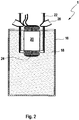
- the winding material 20 is shown after it has been completely immersed from the coating fluid 18 and after sufficient liquid coating fluid 18 has been able to drip off during a dripping phase.
- the drip-back protection 12 with the collecting section 14 is arranged between the winding material 20 and the coating fluid 18.
- the stripping element 6 of the functional surface cleaning devices 2 is brought into contact with the functional surface 24.
- FIG 5 is a partially enlarged schematic view of the cleaning device 1 shown.
- the functional surface cleaning device 2 having a holder 4 and a stripping element 6 is shown in detail.
- the stripping element 6 is brought into contact with the functional surface 24 and guides the coating fluid 18 adhering to the functional surface 24 in the direction of the drip back protection 12.
- the functional surface cleaning device 2 shown has a tubular body 8 and a suction nozzle 10.
- the suction nozzle 10 has a suction opening 28 directed in the direction of the functional surface 24 and connected to the tubular body 8 in a fluid-conducting manner.
- a negative pressure is formed in the tubular body 8, by means of which excess coating fluid 18 is cleaned from the functional surface 24.
- the cleaned-off coating fluid 18 is diverted through the tubular body 8 and does not collect on the drip guard 12.
- the functional surface cleaning device 2 shown has an endless belt 34 guided by two deflecting rollers 30 spaced apart from one another and driven by a drive roller 32.
- the endless belt 34 is made of an absorbent material and, in a contact section 36, forms a cleaning surface 38 facing the functional surface 24.
- the cleaning surface 38 is brought into contact with the functional surface 24.
- excess coating fluid 18 is sucked up by the endless belt 34 and conveyed in the direction of an extrusion device 40.
- the press-out device 40 is formed from one of the deflection rollers 30 and a press-out roller 42. In the extrusion device 40, the endless belt 34 is squeezed by the deflection roller 30 and the extrusion roller 42 and the coating fluid 18 taken up is discharged from the endless belt 34.
Description
- Die Erfindung betrifft eine Reinigungsvorrichtung zum Abreinigen eines Wickelguts, das im Tauchverfahren in einem ein Beschichtungsfluid umfassenden Beschichtungsfluidbehälter beschichtet worden ist, wobei die Reinigungsvorrichtung zumindest eine Funktionsflächenreinigungseinrichtung aufweist, mittels der überschüssiges Beschichtungsfluid von einer Funktionsfläche des Wickelguts unmittelbar mit oder beim Austauchen aus dem Beschichtungsfluid abreinigbar ist.
- Ein wesentlicher Bestandteil der Herstellung von Elektromotoren ist die Herstellung von Spulen. Spulen umfassen üblicherweise einen Spulenkern, um den ein Draht gewickelt ist. Ein derartiges Bauteil, das einen gewickelten Draht umfasst, wird auch als Wickelgut bezeichnet.
- Ferner umfassen Wickelgüter häufig auch Funktionsflächen, beispielsweise Abstandshalter, Lagerflächen oder dergleichen. Bei der Herstellung von Wickelgütern kann das Wickelgut beschichtet und/oder imprägniert werden. Aufgrund der durch den gewickelten Draht ausgebildeten feinen Struktur, ist der Übergang zwischen Beschichten, also einer reinen Oberflächenbehandlung, und Imprägnieren, also einer Behandlung, die auch ein inneres des Objekts betrifft, fließend. Im Folgenden wird unter dem Begriff Beschichten auch ein Imprägnieren verstanden.
- Aufgrund der angesprochenen feinen Oberflächenstruktur, erfolgt das Beschichten von Wickelgütern üblicherweise mittels eines Tauchverfahrens. Hierbei stellt sich die Herausforderung, dass das Wickelgut gleichmäßig benetzt werden soll, dass aber flüssige Beschichtungsmittel, im folgenden Beschichtungsfluide, dazu neigen nach einem Austauchen des Wickelguts Tropfnasen zu bilden. Diese Tropfenasen sind insbesondere im Bereich der Funktionsflächen nachteilig, da sie einer maßhaltigen Ausgestaltung im Bereich der Funktionsflächen entgegenstehen. Aufgrund der geringen Toleranzen bei elektronischen Bauteilen im Bereich von unter 0,1 mm machen eventuell vorhandene Tropfnasen es erforderlich, dass die Funktionsflächen nach dem Beschichten nachgearbeitet werden müssen.
- Um eine möglichst gleichmäßige Schichtdicke zu erreichen sind aus dem Stand der Technik unterschiedliche Reinigungsvorrichtungen bekannt, die unter anderem in der
DE 10 2010 060 515 B4 und derDE 10 2009 045 200 A1 beschrieben sind. Das Abreinigen der beschichteten Wickelgüter, erfolgt hierbei mittels einer separaten Vorrichtung, außerhalb des Tauchbeckenbereiches mit gasförmigen Medien unter hohem Druck und hohem Volumenstrom. - Hierbei ist insbesondere nachteilig, dass das Wickelgut nach dem Austauchen zunächst an eine weitere Position verfahren werden muss, was eine Prozessdauer verlängert. Darüber hinaus weisen die beschriebenen Verfahren einen hohen Energiebedarf sowie hohe Geräusch- und Aerosolemissionen auf, wobei insbesondere die Aerosolemissionen leistungsfähige Absauganlagen erforderlich machen, um eine angemessene Luftqualität zu erhalten. Mit den bekannten Verfahren und Vorrichtungen ist es auch nicht möglich, auf der gesamten Oberfläche des Wickelguts eine einheitliche Schichtdicke auszubilden, insbesondere werden Tropfnasen im Bereich der Funktionsflächen nicht verhindert, sodass mit aufwändigen Reinigungsprozessen nachgearbeitet werden muss.
- Gattungsgemäße Reinigungsvorrichtungen sind bekannt aus
JP H09 56124 A GB 915 328 A GB 807 805 A - Eine Aufgabe eines Ausführungsbeispiels der Erfindung ist, eine Reinigungsvorrichtung zur Verfügung zu stellen mit der Prozessdauer, Emissionen und Abweichungen von der gewünschten Schichtdicke verringerbar sind
- Diese Aufgabe wird erfindungsgemäß dadurch gelöst, dass die Reinigungsvorrichtung zumindest eine in und/ oder um das Wickelgut bewegbare Düse aufweist, mittels der das Wickelgut zumindest abschnittsweise mittels eines mit Druck beaufschlagten, insbesondere gasförmigen, Fluids abreinigbar ist und dass die Reinigungsvorrichtung einen Rücktropfschutz aufweist, der zwischen dem aus dem Beschichtungsfluid ausgetauchten Wickelgut und einer Beschichtungsfluidoberfläche des Beschichtungsfluids anordenbar ist und durch den ein Rücktropfen von überschüssigem Beschichtungsfluid in den Beschichtungsfluidbehälter verhindert ist, wobei der Rücktropfschutz einen Sammelabschnitt aufweist in dem durch den Rücktropfschutz aufgefangenes Beschichtungsfluid gesammelt wird
- Durch eine derartige Funktionsflächenreinigungseinrichtung wird es ermöglicht, dass Funktionsflächen des Wickelguts nach einem Austauchen des Wickelguts aus dem Beschichtungsfluid punktuell und zielgerichtet abgereinigt werden kann. Es ist vorgesehen, dass das Abreinigen mittels der Funktionsflächenreinigungseinrichtung erfolgt, solange das Beschichtungsfluid noch teilweise flüssig ist, wodurch überschüssiges Beschichtungsfluid sowohl entfernt, als auch verteilt werden kann um eine einheitliche Schichtdicke zu erreichen.
- Durch das unmittelbare Abreinigen nach dem Austauchen, werden Transferwege reduziert. Ferner kann die Reinigungsvorrichtung bauteilreduziert ausgebildet werden, da auf Auffangvorrichtungen verzichtet werden kann, da abtropfendes Beschichtungsfluid direkt in den Beschichtungsfluidbehälter zurückgeführt wird.
- Die Funktionsfläche kann einen Blech-Stator des Blechpakets umfassen.
- Durch den Rücktropfschutz wird verhindert, dass bereits teilweise ausgehärtetes Beschichtungsfluid in den Beschichtungsfluidbehälter zurücktropft und dort eventuell das im Beschichtungsfluidbehälter angeordnete Beschichtungsfluid verunreinigt. Dies ist insbesondere vorteilhaft, wenn ein Aushärtungsprozess des Beschichtungsfluids irreversibel ist.
- Durch den Sammelabschnitt ist es ermöglicht, dass auch große Mengen überschüssigen Beschichtungsfluids mit dem Rücktropfschutz aufgefangen werden können, ohne dass das Risiko einer Verunreinigung des in dem Beschichtungsfluidbehälter angeordneten Beschichtungsfluids besteht. Es ist auch möglich und vorgesehen, dass der Sammelabschnitt einen Ablauf aufweist, durch den das aufgefangene Beschichtungsfluid abgeführt werden kann, beispielsweise zu einer Entsorgungs- und/oder Wiederaufbereitungseinrichtung.
- Als besonders vorteilhaft hat es sich erwiesen, wenn eine Vielzahl von in einer Umfangsrichtung um das Wickelgut herum angeordnete Düsen das Wicklegut mittels Druckluft abreinigen und dabei in Richtung des Beschichtungsfluidbehälters verfahren werden, sodass ausreichend flüssiges, überschüssiges Beschichtungsfluid in Richtung des Beschichtungsmittelbehälters verlagert wird und abtropfen kann.
- Darüber hinaus erweist es sich als vorteilhaft, wenn die Funktionsflächenreinigungseinrichtung eine Halterung und ein an der Halterung festgelegtes und sich von der Halterung in Richtung der Funktionsfläche erstreckendes streifenförmiges Abstreifelement aufweist, das mit der Funktionsfläche in Anlage bringbar ist und mittels dessen überschüssiges Beschichtungsfluid von der Funktionsfläche abreinigbar ist.
- In Weiterbildung letztgenannter Ausführungsform erweist es sich als vorteilhaft, wenn das Abstreifelement aus einem elastischen Material gefertigt ist. Eine vorteilhafte Ausgestaltung des Abstreifelements weist einen Aufbau auf, der einer Wischlippe eines Scheibenwischers für ein Automobil ähnelt.
- Es ist auch möglich, dass das Abreinigen berührungslos erfolgen kann, nämlich indem das Abstreifelement stets in einem definierten Abstand zu der Funktionsfläche geführt wird, sodass eine Ausbildung einer definierten Schichtdicke ermöglicht ist.
- Ferner ist bei einer Ausführungsform der Reinigungsvorrichtung vorgesehen, dass die Funktionsflächenreinigungseinrichtung einen Rohrkörper und zumindest eine Saugdüse mit einer in Richtung der Funktionsfläche gerichteten und mit dem Rohrkörper fluidleitend verbundenen Saugöffnung aufweist, mittels derer überschüssiges Beschichtungsfluid unter Nutzung eines in dem Rohrkörper ausbildbaren Unterdrucks von der Funktionsfläche abreinigbar ist. Besonders vorteilhaft ist es, wenn die Saugdüse aus einem elastischen Material gefertigt ist, beispielsweise aus einem Elastomer.
- In Weiterbildung letztgenannter Ausführungsform erweist es sich als vorteilhaft, wenn die Funktionsflächenreinigungseinrichtung eine Sensorik zum Erfassen überschüssigen Beschichtungsfluids aufweist, die mit einer Steuerung der Funktionsflächenreinigungseinrichtung verbunden ist, um so ein zielgerichtetes Abreinigen der Funktionsfläche zu ermöglichen. Die Sensorik kann beispielsweise Ultraschallsensoren, Laserentfernungsmesser, Kamerasensoren oder ähnliches aufweisen.
- Darüber hinaus erweist es sich als zweckmäßig, wenn die Funktionsflächenreinigungseinrichtung ein durch zumindest zwei voneinander beabstandete Umlenkwalzen geführtes und von zumindest einer Antriebswalze antreibbares Endlosband aus einem saugfähigen Material aufweist, das in einem Anlageabschnitt eine der Funktionsfläche zugewandte Reinigungsfläche ausbildet, die zumindest abschnittsweise mit der Funktionsfläche in Anlage bringbar ist. Im Bereich der Reinigungsfläche kann überschüssiges Beschichtungsfluid von dem Endlosband aufgesaugt und in Richtung einer Auspresseinrichtung gefördert werden, die durch zumindest eine der Umlenkwalzen und ein auf einer der Umlenkwalze gegenüberliegenden Seite des Endlosbandes angeordnetes Auspressmittel gebildet ist und in der das Endlosband durch die Umlenkwalze und das Auspressmittel gequetscht und das aufgenommene Beschichtungsfluid in aus dem Endlosband ausgetragen wird.
- Die dergestalt ausgebildete Funktionsflächenreinigungseinrichtung entspricht in ihrer äußeren Form im Wesentlichen den sogenannten Band- oder Fingerschleifern. Hierdurch ist es ermöglicht, dass das Endlosband flexibel genug gehalten ist, um sich einfach an eine Form der Funktionsfläche anpassen zu können. Besonders vorteilhaft ist diese Ausführungsform bei Funktionsflächen mit einem konvexen Verlauf.
- Ferner können Antriebswalzen zum Umlenken des Endlosbands verwendet werden und die Umlenkwalzen Antriebsmittel aufweisen. Welche der Walzen das Endlosband antreibt und welche es umlenkt, beziehungsweise ob kombinierte Umlenk-Antriebswalzen verwendet werden, richtet sich nach den konstruktiven Erfordernissen des Einzelfalls.
- Bei einer vorteilhaften Ausgestaltung der letztgenannten Ausführungsform ist es vorgesehen, dass ein zwischen den Umlenkwalzen ausgebildeter Abstand zumindest die Ausdehnung der Funktionsfläche umfasst. Hierdurch ist es ermöglicht, dass ein großer Abschnitt der Funktionsfläche ohne eine Positionsänderung der Funktionsflächenreinigungseinrichtung abreinigbar ist.
- Darüber hinaus kann das Auspressmittel als eine Auspresswalze ausgebildet sein.
- Es ist vorgesehen, dass der Rücktropfschutz beispielsweise ein Platte, eine Wanne, ein Becken, eine Abdeckplane oder Ähnliches sein und/oder umfassen kann. Der Rücktropfschutz kann auch als ein eigenständiges Konstruktionselement ausgebildet sein, das unabhängig von der Reinigungsvorrichtung verlagerbar sein kann.
- Die Aufgabe wird zudem gelöst durch ein Verfahren zum Reinigen eines im Tauchverfahren beschichteten Wickelguts, das in einem ein, Beschichtungsfluid umfassenden Beschichtungsfluidbehälter zumindest abschnittweise eingetaucht ist, mit den Schritten:
- a. Austauchen des Wickelguts;
- b. Entfernen von überschüssigem Beschichtungsfluid vom Wickelgut mittels mindestens einer zuvor beschriebenen Reinigungsvorrichtung.
- Durch das zügige Abreinigen des noch flüssigen und/oder gelförmigen Beschichtungsfluids, ohne dass das Wickelgut zunächst zu einer Abreinigungsstation verfahren wird, kann das Abreinigen insbesondere schneller, präziser und energieeffizienter durchgeführt werden, als dies mit den aus dem Stand der Technik bekannten Verfahren möglich ist.
- Ferner ist es auch möglich, dass die Anordnung des Wickelguts in Relation zu der Beschichtungsfluidoberfläche prozess- und/oder konstruktionstechnischen Bedürfnissen angepasst sein kann, etwa wenn in einem Bereich der Funktionsfläche eine stärkere Schichtdicke des Beschichtungsfluids ausgebildet werden soll.
- Schließlich ist bei einer Ausführungsform des Verfahrens vorgesehen, dass nach das Abreinigen mittels einer Reinigungsvorrichtung erfolgt, die zumindest eine in und/oder um das Wickelgut bewegbare Düse aufweist und das Wickelgut bereits während des Austauchens von der Düse mittels des mit Druck beaufschlagten, insbesondere gasförmigen, Fluids abgereinigt wird.
- Weitere Merkmale, Einzelheiten und Vorteile der Erfindung ergeben sich aus den beigefügten Patentansprüchen, aus der zeichnerischen Darstellung und nachfolgenden Beschreibung einer bevorzugten Ausführungsform der Abtrennvorrichtung.
- In der Zeichnung zeigt:
- Figur 1
- eine schematische dargestellte Vorderansicht einer Reinigungsvorrichtung mit Wickelgut;
- Figur 2 u. 3
- eine schematisch dargestellte Vorderansichten der Reinigungsvorrichtung gemäß
Figur 1 mit austauchendem Wickelgut; - Figur 4
- eine schematisch dargestellte Vorderansicht der Reinigungsvorrichtung gemäß
Figur 1 mit ausgetauchtem Wickelgut; - Figur 5 - 7
- ausschnittsweise vergrößerte, schematisch dargestellte Vorderansichten von verschiedener Ausführungsformen von Funktionsflächenreinigungseinrichtungen.
- In
Figur 1 ist eine Ausführungsform einer Reinigungsvorrichtung 1 gezeigt, die eine Funktionsflächenreinigungseinrichtung 2 aus einer Halterung 4 und einem Abstreifelement 6, eine Funktionsflächenreinigungseinrichtung 2 aus einer an einem Rohrkörper 8 festgelegten Saugdüse 10 und einen flächig ausgebildeten Rücktropfschutz 12 mit einem Sammelabschnitt 14 aufweist. - Die Reinigungsvorrichtung 1 ist neben einem Beschichtungsfluidbehälter 16 angeordnet in dem ein Beschichtungsfluid 18 angeordnet ist. Oberhalb des Beschichtungsfluidbehälters 16 ist das Wickelgut 20 angeordnet, das von Tauchhalterungen 22 gehalten ist. Auf seiner dem Beschichtungsfluidbehälter 16 zugewandten Seite weist das Wickelgut 20 eine Funktionsfläche 24 auf. Diese umfasst einen Blech-Stator des Blechpakets umfasst. Benachbart zu der Funktionsfläche 24 sind zwei mit Druckluft beaufschlagbare und entlang der Tauchhalterungen 22 verfahrbare Düsen 26 der Reinigungsvorrichtung 1 angeordnet.
- In den
Figuren 2 und3 ist gezeigt, wie das in das Beschichtungsfluid 18 getauchte Wickelgut 20 ausgetaucht wird. Dabei werden die Düsen 26 mit Druckluft beaufschlagt und derart entlang der Tauchhalterungen 22 verfahren, dass an dem Wickelgut 20 anhaftendes Beschichtungsfluid 18 abgeblasen wird. - In
Figur 4 ist das Wickelgut 20 gezeigt, nachdem es vollständig aus dem Beschichtungsfluid 18 ausgetaucht ist und nachdem ausreichend flüssiges Beschichtungsfluid 18 während einer Abtropfphase abtropfen konnte. Um ein weiteres Abtropfen des immer weiter aushärtenden und gelartig werdenden Beschichtungsfluids 18 zu verhindern, ist zwischen dem Wickelgut 20 und dem Beschichtungsfluid 18 der Rücktropfschutz 12 mit dem Sammelabschnitt 14 angeordnet. Um das sich im Bereich der Funktionsfläche 24 sammelnde Beschichtungsfluid 18 abzureinigen, ist das Abstreifelement 6 der Funktionsflächenreinigungseinrichtungen 2 mit der Funktionsfläche 24 in Anlage gebracht. - Das Beschichtungsfluid 18, das nach wie vor flüssig genug ist, um sich selbstständig von dem Wickelgut 20 zu lösen, wird von dem Rücktropfschutz 12 aufgefangen und sammelt sich in dem Sammelabschnitt 14.
- In
Figur 5 ist eine ausschnittsweise vergrößert dargestellte schematische Ansicht der Reinigungsvorrichtung 1 gezeigt. Im Detail ist die eine Halterung 4 und einem Abstreifelement 6 aufweisende Funktionsflächenreinigungseinrichtung 2 gezeigt. Das Abstreifelement 6 ist mit der Funktionsfläche 24 in Anlage gebracht und leitet das an der Funktionsfläche 24 haftende Beschichtungsfluid 18 in Richtung des Rücktropfschutzes 12. - Die in
Figur 6 gezeigte Funktionsflächenreinigungseinrichtung 2 weist einen Rohrkörper 8 und eine Saugdüse 10 auf. Die Saugdüse 10 weist eine in Richtung der Funktionsfläche 24 gerichteten und mit dem Rohrkörper 8 fluidleitend verbundenen Saugöffnung 28 auf. In dem Rohrkörper 8 ist ein Unterdruck ausgebildet durch den überschüssiges Beschichtungsfluid 18 von der Funktionsfläche 24 abgereinigt wird. Das abgereinigte Beschichtungsfluid 18 wird durch den Rohrkörper 8 hindurch abgeleitet und sammelt sich nicht auf dem Rücktropfschutz 12. - Die in
Figur 7 gezeigte Funktionsflächenreinigungseinrichtung 2 weist ein durch zwei voneinander beabstandete Umlenkwalzen 30 geführtes und von einer Antriebswalze 32 angetriebenes Endlosband 34 auf. Das Endlosband 34 ist aus einem saugfähigen Material hergestellt und bildet in einem Anlageabschnitt 36 eine der Funktionsfläche 24 zugewandte Reinigungsfläche 38 aus. Die Reinigungsfläche 38 ist mit der Funktionsfläche 24 in Anlage gebracht. Im Bereich der Reinigungsfläche 38 wird überschüssiges Beschichtungsfluid 18 von dem Endlosband 34 aufgesaugt und in Richtung einer Auspresseinrichtung 40 gefördert. Die Auspresseinrichtung 40 ist aus einer der Umlenkwalzen 30 und einer Auspresswalze 42 gebildet. In der Auspresseinrichtung 40 wird das Endlosband 34 durch die Umlenkwalze 30 und die Auspresswalze 42 gequetscht und das aufgenommene Beschichtungsfluid 18 aus dem Endlosband 34 ausgetragen. -
- 1.
- Reinigungsvorrichtung
- 2.
- Funktionsflächenreinigungseinrichtung
- 4.
- Halterung
- 6.
- Abstreifelement
- 8.
- Rohrkörper
- 10.
- Saugdüse
- 12.
- Rücktropfschutz
- 14.
- Sammelabschnitt
- 16.
- Beschichtungsfluidbehälter
- 18.
- Beschichtungsfluid
- 20.
- Wickelgut
- 22.
- Tauchhalterung
- 24.
- Funktionsfläche
- 26.
- Düse
- 28.
- Saugöffnung
- 30.
- Umlenkwalze
- 32.
- Antriebswalze
- 34.
- Endlosband
- 36.
- Anlageabschnitt
- 38.
- Reinigungsfläche
- 40.
- Auspresseinrichtung
- 42.
- Auspresswalze
Claims (6)
- Reinigungsvorrichtung (1) zum Abreinigen eines Wickelguts (20), das im Tauchverfahren in einem ein Beschichtungsfluid (18) umfassenden Beschichtungsfluidbehälter (16) beschichtet worden ist, wobei die Reinigungsvorrichtung (1) zumindest eine Funktionsflächenreinigungseinrichtung (2) aufweist, mittels der überschüssiges Beschichtungsfluid (18) von einer Funktionsfläche (24) des Wickelguts (20) unmittelbar mit oder beim Austauchen aus dem Beschichtungsfluid (18) abreinigbar ist, dadurch gekennzeichnet, dass die Reinigungsvorrichtung (1) zumindest eine in und/ oder um das Wickelgut (20) bewegbare Düse (26) aufweist, mittels der das Wickelgut (20) zumindest abschnittsweise mittels eines mit Druck beaufschlagten, insbesondere gasförmigen, Fluids abreinigbar ist und dass die Reinigungsvorrichtung (1) einen Rücktropfschutz (12) aufweist, der zwischen dem aus dem Beschichtungsfluid (18) ausgetauchten Wickelgut (20) und einer Beschichtungsfluidoberfläche des Beschichtungsfluids (18) anordenbar ist und durch den ein Rücktropfen von überschüssigem Beschichtungsfluid (18) in den Beschichtungsfluidbehälter (16) verhindert ist, wobei der Rücktropfschutz (12) einen Sammelabschnitt (14) aufweist in dem durch den Rücktropfschutz (12) aufgefangenes Beschichtungsfluid (18) gesammelt wird
- Reinigungsvorrichtung (1) nach Anspruch 1, dadurch gekennzeichnet, dass die Funktionsflächenreinigungseinrichtung (2) eine Halterung (4) und ein an der Halterung (4) festgelegtes und sich von der Halterung (4) in Richtung der Funktionsfläche (24) erstreckendes streifenförmiges Abstreifelement (6) aufweist, das mit der Funktionsfläche (24) in Anlage bringbar ist und mittels dessen überschüssiges Beschichtungsfluid (18) von der Funktionsfläche (24) abreinigbar ist.
- Reinigungsvorrichtung (1) nach Anspruch 1 oder 2, dadurch gekennzeichnet, dass die Funktionsflächenreinigungseinrichtung (2) einen Rohrkörper (8) und zumindest eine Saugdüse (10) mit einer in Richtung der Funktionsfläche (24) gerichteten und mit dem Rohrkörper (8) fluidleitend verbundenen Saugöffnung (28) aufweist, mittels derer überschüssiges Beschichtungsfluid (18) unter Nutzung eines in dem Rohrkörper (8) ausbildbaren Unterdrucks von der Funktionsfläche (24) abreinigbar ist.
- Reinigungsvorrichtung (1) nach einem der vorhergehenden Ansprüche, dadurch gekennzeichnet, dass die Funktionsflächenreinigungseinrichtung (2) ein durch zumindest zwei voneinander beabstandete Umlenkwalzen (30) geführtes und von zumindest einer Antriebswalze (32) antreibbares Endlosband (34) aus einem saugfähigen Material aufweist, das in einem Anlageabschnitt (36) eine der Funktionsfläche (24) zugewandte Reinigungsfläche (38) umfasst, die zumindest abschnittsweise mit der Funktionsfläche (24) in Anlage bringbar ist.
- Verfahren zum Reinigen eines im Tauchverfahren beschichteten Wickelguts (20), das in einem ein, Beschichtungsfluid (18) umfassenden Beschichtungsfluidbehälter (16) zumindest abschnittweise eingetaucht ist, mit den Schritten:a. Austauchen des Wickelguts (20);b. Abreinigen bzw. Entfernen von überschüssigem Beschichtungsfluid (18) vom Wickelgut (20) mittels mindestens einer Reinigungsvorrichtung (1) nach einem der Ansprüche 1 bis 4.
- Verfahren nach Anspruche 5, dadurch gekennzeichnet, dass das Abreinigen mittels einer Reinigungsvorrichtung (1) nach einem der Ansprüche 1 bis 4 erfolgt und das Wickelgut (20) bereits während des Austauchens von zumindest einer Düse (26) mittels des mit Druck beaufschlagten, insbesondere gasförmigen, Fluids abgereinigt wird.
Applications Claiming Priority (1)
| Application Number | Priority Date | Filing Date | Title |
|---|---|---|---|
| DE102018121708.0A DE102018121708A1 (de) | 2018-09-05 | 2018-09-05 | Reinigungsvorrichtung und Verfahren zum Reinigen eines im Tauchverfahren beschichteten Körpers |
Related Parent Applications (1)
| Application Number | Title | Priority Date | Filing Date |
|---|---|---|---|
| DE102018121708 Previously-Filed-Application | 2018-09-05 |
Publications (2)
| Publication Number | Publication Date |
|---|---|
| EP3621186A1 EP3621186A1 (de) | 2020-03-11 |
| EP3621186B1 true EP3621186B1 (de) | 2021-03-17 |
Family
ID=67437784
Family Applications (1)
| Application Number | Title | Priority Date | Filing Date |
|---|---|---|---|
| EP19186208.5A Active EP3621186B1 (de) | 2018-09-05 | 2019-07-15 | Reinigungsvorrichutng und verfahren zum reinigen eines im tauchverfahren beschichteten körpers |
Country Status (4)
| Country | Link |
|---|---|
| EP (1) | EP3621186B1 (de) |
| CN (1) | CN110877021B (de) |
| DE (1) | DE102018121708A1 (de) |
| HU (1) | HUE054240T2 (de) |
Cited By (1)
| Publication number | Priority date | Publication date | Assignee | Title |
|---|---|---|---|---|
| EP4008523B1 (de) * | 2020-12-03 | 2023-11-29 | Lithoz GmbH | Verfahren und vorrichtung zum schichtweisen aufbau eines bauteils aus photopolymerisierbarem material |
Families Citing this family (1)
| Publication number | Priority date | Publication date | Assignee | Title |
|---|---|---|---|---|
| DE102021108257A1 (de) | 2021-03-31 | 2022-10-06 | Meier Prozesstechnik GmbH | Imprägnieren eines Stators für eine elektrische Maschine |
Citations (2)
| Publication number | Priority date | Publication date | Assignee | Title |
|---|---|---|---|---|
| JPH08206572A (ja) * | 1995-02-01 | 1996-08-13 | C Uyemura & Co Ltd | 表面処理用搬送装置のドリップ処理装置 |
| US5902402A (en) * | 1995-01-05 | 1999-05-11 | Steag Microtech Gmbh | Device for chemical wet treatment |
Family Cites Families (13)
| Publication number | Priority date | Publication date | Assignee | Title |
|---|---|---|---|---|
| GB807805A (en) * | 1956-06-15 | 1959-01-21 | Ilford Ltd | Improvements in or relating to coating apparatus |
| DE1018552B (de) * | 1956-09-01 | 1957-10-31 | Ernst Roederstein G M B H | Verfahren zum Verschliessen der stirnseitigen Hohlraeume von rohraehnlichen Kondensatorgehaeusen mit Einrichtung zur Durchfuehrung des Verfahrens |
| GB915328A (en) * | 1959-09-25 | 1963-01-09 | Beloit Iron Works | Improvements in or relating to methods and apparatus for coating paper webs |
| JPS6077650A (ja) * | 1983-10-05 | 1985-05-02 | Toshiba Corp | 絶縁ワニス処理方法およびその装置 |
| JP2510007B2 (ja) * | 1989-06-14 | 1996-06-26 | 新日本製鐵株式会社 | 電動機固定子コイル又は回転子コイルの洗浄方法およびその装置 |
| JPH0956124A (ja) * | 1995-08-18 | 1997-02-25 | Toshiba Corp | 回転子スロット絶縁処理装置 |
| JP2003169451A (ja) * | 2001-11-30 | 2003-06-13 | Toshiba Elevator Co Ltd | 電動機特性回復方法 |
| JP4291034B2 (ja) * | 2003-04-25 | 2009-07-08 | 大日本スクリーン製造株式会社 | 洗浄装置および基板処理装置 |
| DE102008054810A1 (de) * | 2008-12-17 | 2010-06-24 | Robert Bosch Gmbh | Verfahren zum Entfernen eines auf einem Ständereisen geschichteten, elektrisch isolierenden Pulvers, Vorrichtung zur Durchführung des Verfahrens sowie elektrische Maschine mit einem Ständereisen |
| DE102009045200B4 (de) | 2009-09-30 | 2021-02-11 | Inter-Consult Gmbh | Verfahren und Vorrichtung zum Bearbeiten von Bauteilen elektrischer Maschinen |
| DE102010060515B4 (de) | 2010-11-12 | 2016-01-21 | Gottlob Thumm Maschinenbau Gmbh | Imprägnieranlage mit einer Reinigungvorrichtung |
| DE202010017440U1 (de) * | 2010-11-12 | 2011-11-10 | Gottlob Thumm Maschinenbau Gmbh | Imprägnieranlage mit einer Reinigungsvorrichtung |
| CN104759422A (zh) * | 2015-03-12 | 2015-07-08 | 上海工程技术大学 | 一种自洁式太阳能电池板除尘清洗装置 |
-
2018
- 2018-09-05 DE DE102018121708.0A patent/DE102018121708A1/de not_active Withdrawn
-
2019
- 2019-07-15 HU HUE19186208A patent/HUE054240T2/hu unknown
- 2019-07-15 EP EP19186208.5A patent/EP3621186B1/de active Active
- 2019-08-26 CN CN201910791114.5A patent/CN110877021B/zh active Active
Patent Citations (2)
| Publication number | Priority date | Publication date | Assignee | Title |
|---|---|---|---|---|
| US5902402A (en) * | 1995-01-05 | 1999-05-11 | Steag Microtech Gmbh | Device for chemical wet treatment |
| JPH08206572A (ja) * | 1995-02-01 | 1996-08-13 | C Uyemura & Co Ltd | 表面処理用搬送装置のドリップ処理装置 |
Cited By (1)
| Publication number | Priority date | Publication date | Assignee | Title |
|---|---|---|---|---|
| EP4008523B1 (de) * | 2020-12-03 | 2023-11-29 | Lithoz GmbH | Verfahren und vorrichtung zum schichtweisen aufbau eines bauteils aus photopolymerisierbarem material |
Also Published As
| Publication number | Publication date |
|---|---|
| CN110877021B (zh) | 2023-02-28 |
| EP3621186A1 (de) | 2020-03-11 |
| HUE054240T2 (hu) | 2021-08-30 |
| DE102018121708A1 (de) | 2020-03-05 |
| CN110877021A (zh) | 2020-03-13 |
Similar Documents
| Publication | Publication Date | Title |
|---|---|---|
| EP3621186B1 (de) | Reinigungsvorrichutng und verfahren zum reinigen eines im tauchverfahren beschichteten körpers | |
| DE102005004754A1 (de) | Verfahren zur Nachreinigung von abisolierten Bereichen einer elektrischen Leitung | |
| DE19955066C2 (de) | Verfahren und Vorrichtung zum Entfernen von Verunreinigungen von Oberflächen | |
| EP3530364A1 (de) | Hochdruckreinigungsvorrichtung für endlosmaterial | |
| DE60132240T2 (de) | Vorrichtung zur tauchbeschichtung eines metallstreifens | |
| DE2606522C2 (de) | Verfahren und Vorrichtung zum Kennzeichnen von Metall | |
| DE202010017440U1 (de) | Imprägnieranlage mit einer Reinigungsvorrichtung | |
| EP0688878B1 (de) | Verfahren zur Nachbehandlung geschweisster Platinen | |
| EP1563919B1 (de) | Vorrichtung zum Reinigen der Oberfläche von zylindrischen Körpern, wie Walzen oder Rollen | |
| DE3409689C1 (de) | Lackieranlage mit einem maschinell geführten Sprühorgan | |
| DE102006054622A1 (de) | Vorrichtung zum Reinigen eines Mischkopfes einer Anlage zum Befüllen von Kunststoffformen | |
| EP1386709A1 (de) | Verfahren und Vorrichtung zum Aufnehmen eines Plastifikates | |
| EP0570738B1 (de) | Verfahren und Vorrichtung zum Beschichten von Hohlkörpern | |
| DE3915549C2 (de) | ||
| DE102012216400B4 (de) | Vorrichtung und Verfahren zur Reinigung einer Oberfläche | |
| EP0291443B1 (de) | Verfahren und Vorrichtung zum Auftragen eines flüssigen Behandlungsmittels auf Stahlrohre | |
| DE202005021882U1 (de) | Transportable Reinigungsvorrichtung | |
| DE3047671C2 (de) | Verfahren zum kontinuierlichen schmelzflüssigen Überziehen von Metallteilen mit einer lötfähigen Schicht aus Zinn oder Zinn-Blei-Legierung und Vorrichtung zur Durchführung eines solchen Verfahrens | |
| WO2007090637A1 (de) | Verfahren und vorrichtung zum reinigen von werkstücken | |
| DE10304328B3 (de) | Vorrichtung und Verfahren zum Reinigen einer technischen Oberfläche | |
| DE102010005760A1 (de) | Wellrohr-Innenreinigung und Vorrichtung dazu | |
| DE3404574C2 (de) | Einrichtung zur Inspektion eines Kernreaktorbrennelements | |
| DE102015100034A1 (de) | Reinigungsvorrichtung für Backplatten einer Backautomatenanlage | |
| DE202005005698U1 (de) | Komponente für eine Lackiereinrichtung und Vorrichtung zu ihrer Entlackung | |
| DE10110026A1 (de) | Einrichtung zur Reinigung von Walzen |
Legal Events
| Date | Code | Title | Description |
|---|---|---|---|
| STAA | Information on the status of an ep patent application or granted ep patent |
Free format text: STATUS: EXAMINATION IS IN PROGRESS |
|
| PUAI | Public reference made under article 153(3) epc to a published international application that has entered the european phase |
Free format text: ORIGINAL CODE: 0009012 |
|
| 17P | Request for examination filed |
Effective date: 20190715 |
|
| AK | Designated contracting states |
Kind code of ref document: A1 Designated state(s): AL AT BE BG CH CY CZ DE DK EE ES FI FR GB GR HR HU IE IS IT LI LT LU LV MC MK MT NL NO PL PT RO RS SE SI SK SM TR |
|
| AX | Request for extension of the european patent |
Extension state: BA ME |
|
| RBV | Designated contracting states (corrected) |
Designated state(s): AL AT BE BG CH CY CZ DE DK EE ES FI FR GB GR HR HU IE IS IT LI LT LU LV MC MK MT NL NO PL PT RO RS SE SI SK SM TR |
|
| GRAP | Despatch of communication of intention to grant a patent |
Free format text: ORIGINAL CODE: EPIDOSNIGR1 |
|
| STAA | Information on the status of an ep patent application or granted ep patent |
Free format text: STATUS: GRANT OF PATENT IS INTENDED |
|
| RIC1 | Information provided on ipc code assigned before grant |
Ipc: H02K 15/12 20060101AFI20200923BHEP Ipc: B05C 11/06 20060101ALN20200923BHEP Ipc: B08B 3/02 20060101ALN20200923BHEP Ipc: B05C 3/09 20060101ALN20200923BHEP Ipc: B08B 1/00 20060101ALN20200923BHEP Ipc: B08B 5/02 20060101ALN20200923BHEP |
|
| INTG | Intention to grant announced |
Effective date: 20201028 |
|
| GRAS | Grant fee paid |
Free format text: ORIGINAL CODE: EPIDOSNIGR3 |
|
| GRAA | (expected) grant |
Free format text: ORIGINAL CODE: 0009210 |
|
| STAA | Information on the status of an ep patent application or granted ep patent |
Free format text: STATUS: THE PATENT HAS BEEN GRANTED |
|
| AK | Designated contracting states |
Kind code of ref document: B1 Designated state(s): AL AT BE BG CH CY CZ DE DK EE ES FI FR GB GR HR HU IE IS IT LI LT LU LV MC MK MT NL NO PL PT RO RS SE SI SK SM TR |
|
| REG | Reference to a national code |
Ref country code: GB Ref legal event code: FG4D Free format text: NOT ENGLISH |
|
| REG | Reference to a national code |
Ref country code: CH Ref legal event code: EP |
|
| REG | Reference to a national code |
Ref country code: DE Ref legal event code: R096 Ref document number: 502019001010 Country of ref document: DE |
|
| REG | Reference to a national code |
Ref country code: IE Ref legal event code: FG4D Free format text: LANGUAGE OF EP DOCUMENT: GERMAN |
|
| REG | Reference to a national code |
Ref country code: AT Ref legal event code: REF Ref document number: 1373165 Country of ref document: AT Kind code of ref document: T Effective date: 20210415 |
|
| REG | Reference to a national code |
Ref country code: SE Ref legal event code: TRGR |
|
| REG | Reference to a national code |
Ref country code: SK Ref legal event code: T3 Ref document number: E 36866 Country of ref document: SK |
|
| REG | Reference to a national code |
Ref country code: NO Ref legal event code: T2 Effective date: 20210317 |
|
| REG | Reference to a national code |
Ref country code: LT Ref legal event code: MG9D |
|
| PG25 | Lapsed in a contracting state [announced via postgrant information from national office to epo] |
Ref country code: GR Free format text: LAPSE BECAUSE OF FAILURE TO SUBMIT A TRANSLATION OF THE DESCRIPTION OR TO PAY THE FEE WITHIN THE PRESCRIBED TIME-LIMIT Effective date: 20210618 Ref country code: FI Free format text: LAPSE BECAUSE OF FAILURE TO SUBMIT A TRANSLATION OF THE DESCRIPTION OR TO PAY THE FEE WITHIN THE PRESCRIBED TIME-LIMIT Effective date: 20210317 Ref country code: BG Free format text: LAPSE BECAUSE OF FAILURE TO SUBMIT A TRANSLATION OF THE DESCRIPTION OR TO PAY THE FEE WITHIN THE PRESCRIBED TIME-LIMIT Effective date: 20210617 Ref country code: HR Free format text: LAPSE BECAUSE OF FAILURE TO SUBMIT A TRANSLATION OF THE DESCRIPTION OR TO PAY THE FEE WITHIN THE PRESCRIBED TIME-LIMIT Effective date: 20210317 |
|
| REG | Reference to a national code |
Ref country code: NL Ref legal event code: MP Effective date: 20210317 |
|
| REG | Reference to a national code |
Ref country code: HU Ref legal event code: AG4A Ref document number: E054240 Country of ref document: HU |
|
| PG25 | Lapsed in a contracting state [announced via postgrant information from national office to epo] |
Ref country code: RS Free format text: LAPSE BECAUSE OF FAILURE TO SUBMIT A TRANSLATION OF THE DESCRIPTION OR TO PAY THE FEE WITHIN THE PRESCRIBED TIME-LIMIT Effective date: 20210317 Ref country code: LV Free format text: LAPSE BECAUSE OF FAILURE TO SUBMIT A TRANSLATION OF THE DESCRIPTION OR TO PAY THE FEE WITHIN THE PRESCRIBED TIME-LIMIT Effective date: 20210317 |
|
| PG25 | Lapsed in a contracting state [announced via postgrant information from national office to epo] |
Ref country code: NL Free format text: LAPSE BECAUSE OF FAILURE TO SUBMIT A TRANSLATION OF THE DESCRIPTION OR TO PAY THE FEE WITHIN THE PRESCRIBED TIME-LIMIT Effective date: 20210317 |
|
| PG25 | Lapsed in a contracting state [announced via postgrant information from national office to epo] |
Ref country code: EE Free format text: LAPSE BECAUSE OF FAILURE TO SUBMIT A TRANSLATION OF THE DESCRIPTION OR TO PAY THE FEE WITHIN THE PRESCRIBED TIME-LIMIT Effective date: 20210317 Ref country code: LT Free format text: LAPSE BECAUSE OF FAILURE TO SUBMIT A TRANSLATION OF THE DESCRIPTION OR TO PAY THE FEE WITHIN THE PRESCRIBED TIME-LIMIT Effective date: 20210317 Ref country code: SM Free format text: LAPSE BECAUSE OF FAILURE TO SUBMIT A TRANSLATION OF THE DESCRIPTION OR TO PAY THE FEE WITHIN THE PRESCRIBED TIME-LIMIT Effective date: 20210317 |
|
| PG25 | Lapsed in a contracting state [announced via postgrant information from national office to epo] |
Ref country code: IS Free format text: LAPSE BECAUSE OF FAILURE TO SUBMIT A TRANSLATION OF THE DESCRIPTION OR TO PAY THE FEE WITHIN THE PRESCRIBED TIME-LIMIT Effective date: 20210717 Ref country code: PL Free format text: LAPSE BECAUSE OF FAILURE TO SUBMIT A TRANSLATION OF THE DESCRIPTION OR TO PAY THE FEE WITHIN THE PRESCRIBED TIME-LIMIT Effective date: 20210317 Ref country code: PT Free format text: LAPSE BECAUSE OF FAILURE TO SUBMIT A TRANSLATION OF THE DESCRIPTION OR TO PAY THE FEE WITHIN THE PRESCRIBED TIME-LIMIT Effective date: 20210719 Ref country code: RO Free format text: LAPSE BECAUSE OF FAILURE TO SUBMIT A TRANSLATION OF THE DESCRIPTION OR TO PAY THE FEE WITHIN THE PRESCRIBED TIME-LIMIT Effective date: 20210317 |
|
| REG | Reference to a national code |
Ref country code: DE Ref legal event code: R097 Ref document number: 502019001010 Country of ref document: DE |
|
| PLBE | No opposition filed within time limit |
Free format text: ORIGINAL CODE: 0009261 |
|
| STAA | Information on the status of an ep patent application or granted ep patent |
Free format text: STATUS: NO OPPOSITION FILED WITHIN TIME LIMIT |
|
| PG25 | Lapsed in a contracting state [announced via postgrant information from national office to epo] |
Ref country code: ES Free format text: LAPSE BECAUSE OF FAILURE TO SUBMIT A TRANSLATION OF THE DESCRIPTION OR TO PAY THE FEE WITHIN THE PRESCRIBED TIME-LIMIT Effective date: 20210317 Ref country code: DK Free format text: LAPSE BECAUSE OF FAILURE TO SUBMIT A TRANSLATION OF THE DESCRIPTION OR TO PAY THE FEE WITHIN THE PRESCRIBED TIME-LIMIT Effective date: 20210317 Ref country code: AL Free format text: LAPSE BECAUSE OF FAILURE TO SUBMIT A TRANSLATION OF THE DESCRIPTION OR TO PAY THE FEE WITHIN THE PRESCRIBED TIME-LIMIT Effective date: 20210317 |
|
| 26N | No opposition filed |
Effective date: 20211220 |
|
| PG25 | Lapsed in a contracting state [announced via postgrant information from national office to epo] |
Ref country code: SI Free format text: LAPSE BECAUSE OF FAILURE TO SUBMIT A TRANSLATION OF THE DESCRIPTION OR TO PAY THE FEE WITHIN THE PRESCRIBED TIME-LIMIT Effective date: 20210317 |
|
| PG25 | Lapsed in a contracting state [announced via postgrant information from national office to epo] |
Ref country code: MC Free format text: LAPSE BECAUSE OF FAILURE TO SUBMIT A TRANSLATION OF THE DESCRIPTION OR TO PAY THE FEE WITHIN THE PRESCRIBED TIME-LIMIT Effective date: 20210317 |
|
| REG | Reference to a national code |
Ref country code: BE Ref legal event code: MM Effective date: 20210731 |
|
| PG25 | Lapsed in a contracting state [announced via postgrant information from national office to epo] |
Ref country code: IS Free format text: LAPSE BECAUSE OF FAILURE TO SUBMIT A TRANSLATION OF THE DESCRIPTION OR TO PAY THE FEE WITHIN THE PRESCRIBED TIME-LIMIT Effective date: 20210717 Ref country code: LU Free format text: LAPSE BECAUSE OF NON-PAYMENT OF DUE FEES Effective date: 20210715 |
|
| PG25 | Lapsed in a contracting state [announced via postgrant information from national office to epo] |
Ref country code: IE Free format text: LAPSE BECAUSE OF NON-PAYMENT OF DUE FEES Effective date: 20210715 Ref country code: BE Free format text: LAPSE BECAUSE OF NON-PAYMENT OF DUE FEES Effective date: 20210731 |
|
| REG | Reference to a national code |
Ref country code: CH Ref legal event code: PL |
|
| PG25 | Lapsed in a contracting state [announced via postgrant information from national office to epo] |
Ref country code: LI Free format text: LAPSE BECAUSE OF NON-PAYMENT OF DUE FEES Effective date: 20220731 Ref country code: CH Free format text: LAPSE BECAUSE OF NON-PAYMENT OF DUE FEES Effective date: 20220731 |
|
| PGFP | Annual fee paid to national office [announced via postgrant information from national office to epo] |
Ref country code: NO Payment date: 20230320 Year of fee payment: 5 |
|
| PG25 | Lapsed in a contracting state [announced via postgrant information from national office to epo] |
Ref country code: CY Free format text: LAPSE BECAUSE OF FAILURE TO SUBMIT A TRANSLATION OF THE DESCRIPTION OR TO PAY THE FEE WITHIN THE PRESCRIBED TIME-LIMIT Effective date: 20210317 |
|
| PGFP | Annual fee paid to national office [announced via postgrant information from national office to epo] |
Ref country code: CZ Payment date: 20230505 Year of fee payment: 5 |
|
| PGFP | Annual fee paid to national office [announced via postgrant information from national office to epo] |
Ref country code: SK Payment date: 20230621 Year of fee payment: 5 |
|
| PGFP | Annual fee paid to national office [announced via postgrant information from national office to epo] |
Ref country code: IT Payment date: 20230712 Year of fee payment: 5 Ref country code: GB Payment date: 20230724 Year of fee payment: 5 |
|
| PGFP | Annual fee paid to national office [announced via postgrant information from national office to epo] |
Ref country code: SE Payment date: 20230724 Year of fee payment: 5 Ref country code: HU Payment date: 20230426 Year of fee payment: 5 Ref country code: FR Payment date: 20230724 Year of fee payment: 5 Ref country code: DE Payment date: 20230720 Year of fee payment: 5 |