EP3604850A1 - Mécanisme amortisseur unidirectionnel - Google Patents
Mécanisme amortisseur unidirectionnel Download PDFInfo
- Publication number
- EP3604850A1 EP3604850A1 EP18775645.7A EP18775645A EP3604850A1 EP 3604850 A1 EP3604850 A1 EP 3604850A1 EP 18775645 A EP18775645 A EP 18775645A EP 3604850 A1 EP3604850 A1 EP 3604850A1
- Authority
- EP
- European Patent Office
- Prior art keywords
- gear
- damper
- holding member
- holding
- rack
- Prior art date
- Legal status (The legal status is an assumption and is not a legal conclusion. Google has not performed a legal analysis and makes no representation as to the accuracy of the status listed.)
- Pending
Links
Images


Classifications
-
- F—MECHANICAL ENGINEERING; LIGHTING; HEATING; WEAPONS; BLASTING
- F16—ENGINEERING ELEMENTS AND UNITS; GENERAL MEASURES FOR PRODUCING AND MAINTAINING EFFECTIVE FUNCTIONING OF MACHINES OR INSTALLATIONS; THERMAL INSULATION IN GENERAL
- F16F—SPRINGS; SHOCK-ABSORBERS; MEANS FOR DAMPING VIBRATION
- F16F7/00—Vibration-dampers; Shock-absorbers
- F16F7/08—Vibration-dampers; Shock-absorbers with friction surfaces rectilinearly movable along each other
- F16F7/082—Vibration-dampers; Shock-absorbers with friction surfaces rectilinearly movable along each other and characterised by damping force adjustment means
- F16F7/085—Vibration-dampers; Shock-absorbers with friction surfaces rectilinearly movable along each other and characterised by damping force adjustment means resulting in the damping effects being different according to direction of movement
-
- F—MECHANICAL ENGINEERING; LIGHTING; HEATING; WEAPONS; BLASTING
- F16—ENGINEERING ELEMENTS AND UNITS; GENERAL MEASURES FOR PRODUCING AND MAINTAINING EFFECTIVE FUNCTIONING OF MACHINES OR INSTALLATIONS; THERMAL INSULATION IN GENERAL
- F16F—SPRINGS; SHOCK-ABSORBERS; MEANS FOR DAMPING VIBRATION
- F16F7/00—Vibration-dampers; Shock-absorbers
-
- B—PERFORMING OPERATIONS; TRANSPORTING
- B60—VEHICLES IN GENERAL
- B60R—VEHICLES, VEHICLE FITTINGS, OR VEHICLE PARTS, NOT OTHERWISE PROVIDED FOR
- B60R7/00—Stowing or holding appliances inside vehicle primarily intended for personal property smaller than suit-cases, e.g. travelling articles, or maps
- B60R7/04—Stowing or holding appliances inside vehicle primarily intended for personal property smaller than suit-cases, e.g. travelling articles, or maps in driver or passenger space, e.g. using racks
- B60R7/06—Stowing or holding appliances inside vehicle primarily intended for personal property smaller than suit-cases, e.g. travelling articles, or maps in driver or passenger space, e.g. using racks mounted on or below dashboards
-
- F—MECHANICAL ENGINEERING; LIGHTING; HEATING; WEAPONS; BLASTING
- F16—ENGINEERING ELEMENTS AND UNITS; GENERAL MEASURES FOR PRODUCING AND MAINTAINING EFFECTIVE FUNCTIONING OF MACHINES OR INSTALLATIONS; THERMAL INSULATION IN GENERAL
- F16F—SPRINGS; SHOCK-ABSORBERS; MEANS FOR DAMPING VIBRATION
- F16F15/00—Suppression of vibrations in systems; Means or arrangements for avoiding or reducing out-of-balance forces, e.g. due to motion
- F16F15/02—Suppression of vibrations of non-rotating, e.g. reciprocating systems; Suppression of vibrations of rotating systems by use of members not moving with the rotating systems
- F16F15/023—Suppression of vibrations of non-rotating, e.g. reciprocating systems; Suppression of vibrations of rotating systems by use of members not moving with the rotating systems using fluid means
-
- F—MECHANICAL ENGINEERING; LIGHTING; HEATING; WEAPONS; BLASTING
- F16—ENGINEERING ELEMENTS AND UNITS; GENERAL MEASURES FOR PRODUCING AND MAINTAINING EFFECTIVE FUNCTIONING OF MACHINES OR INSTALLATIONS; THERMAL INSULATION IN GENERAL
- F16F—SPRINGS; SHOCK-ABSORBERS; MEANS FOR DAMPING VIBRATION
- F16F9/00—Springs, vibration-dampers, shock-absorbers, or similarly-constructed movement-dampers using a fluid or the equivalent as damping medium
- F16F9/10—Springs, vibration-dampers, shock-absorbers, or similarly-constructed movement-dampers using a fluid or the equivalent as damping medium using liquid only; using a fluid of which the nature is immaterial
- F16F9/12—Devices with one or more rotary vanes turning in the fluid any throttling effect being immaterial, i.e. damping by viscous shear effect only
-
- F—MECHANICAL ENGINEERING; LIGHTING; HEATING; WEAPONS; BLASTING
- F16—ENGINEERING ELEMENTS AND UNITS; GENERAL MEASURES FOR PRODUCING AND MAINTAINING EFFECTIVE FUNCTIONING OF MACHINES OR INSTALLATIONS; THERMAL INSULATION IN GENERAL
- F16F—SPRINGS; SHOCK-ABSORBERS; MEANS FOR DAMPING VIBRATION
- F16F9/00—Springs, vibration-dampers, shock-absorbers, or similarly-constructed movement-dampers using a fluid or the equivalent as damping medium
- F16F9/32—Details
- F16F9/54—Arrangements for attachment
-
- F—MECHANICAL ENGINEERING; LIGHTING; HEATING; WEAPONS; BLASTING
- F16—ENGINEERING ELEMENTS AND UNITS; GENERAL MEASURES FOR PRODUCING AND MAINTAINING EFFECTIVE FUNCTIONING OF MACHINES OR INSTALLATIONS; THERMAL INSULATION IN GENERAL
- F16H—GEARING
- F16H19/00—Gearings comprising essentially only toothed gears or friction members and not capable of conveying indefinitely-continuing rotary motion
- F16H19/02—Gearings comprising essentially only toothed gears or friction members and not capable of conveying indefinitely-continuing rotary motion for interconverting rotary or oscillating motion and reciprocating motion
- F16H19/04—Gearings comprising essentially only toothed gears or friction members and not capable of conveying indefinitely-continuing rotary motion for interconverting rotary or oscillating motion and reciprocating motion comprising a rack
-
- B—PERFORMING OPERATIONS; TRANSPORTING
- B60—VEHICLES IN GENERAL
- B60G—VEHICLE SUSPENSION ARRANGEMENTS
- B60G2204/00—Indexing codes related to suspensions per se or to auxiliary parts
- B60G2204/10—Mounting of suspension elements
- B60G2204/12—Mounting of springs or dampers
- B60G2204/128—Damper mount on vehicle body or chassis
-
- E—FIXED CONSTRUCTIONS
- E05—LOCKS; KEYS; WINDOW OR DOOR FITTINGS; SAFES
- E05B—LOCKS; ACCESSORIES THEREFOR; HANDCUFFS
- E05B83/00—Vehicle locks specially adapted for particular types of wing or vehicle
- E05B83/28—Locks for glove compartments, console boxes, fuel inlet covers or the like
- E05B83/30—Locks for glove compartments, console boxes, fuel inlet covers or the like for glove compartments
-
- E—FIXED CONSTRUCTIONS
- E05—LOCKS; KEYS; WINDOW OR DOOR FITTINGS; SAFES
- E05Y—INDEXING SCHEME RELATING TO HINGES OR OTHER SUSPENSION DEVICES FOR DOORS, WINDOWS OR WINGS AND DEVICES FOR MOVING WINGS INTO OPEN OR CLOSED POSITION, CHECKS FOR WINGS AND WING FITTINGS NOT OTHERWISE PROVIDED FOR, CONCERNED WITH THE FUNCTIONING OF THE WING
- E05Y2201/00—Constructional elements; Accessories therefore
- E05Y2201/20—Brakes; Disengaging means, e.g. clutches; Holders, e.g. locks; Stops; Accessories therefore
- E05Y2201/21—Brakes
-
- E—FIXED CONSTRUCTIONS
- E05—LOCKS; KEYS; WINDOW OR DOOR FITTINGS; SAFES
- E05Y—INDEXING SCHEME RELATING TO HINGES OR OTHER SUSPENSION DEVICES FOR DOORS, WINDOWS OR WINGS AND DEVICES FOR MOVING WINGS INTO OPEN OR CLOSED POSITION, CHECKS FOR WINGS AND WING FITTINGS NOT OTHERWISE PROVIDED FOR, CONCERNED WITH THE FUNCTIONING OF THE WING
- E05Y2201/00—Constructional elements; Accessories therefore
- E05Y2201/20—Brakes; Disengaging means, e.g. clutches; Holders, e.g. locks; Stops; Accessories therefore
- E05Y2201/262—Brakes; Disengaging means, e.g. clutches; Holders, e.g. locks; Stops; Accessories therefore characterised by type of motion
- E05Y2201/266—Brakes; Disengaging means, e.g. clutches; Holders, e.g. locks; Stops; Accessories therefore characterised by type of motion rotary
-
- E—FIXED CONSTRUCTIONS
- E05—LOCKS; KEYS; WINDOW OR DOOR FITTINGS; SAFES
- E05Y—INDEXING SCHEME RELATING TO HINGES OR OTHER SUSPENSION DEVICES FOR DOORS, WINDOWS OR WINGS AND DEVICES FOR MOVING WINGS INTO OPEN OR CLOSED POSITION, CHECKS FOR WINGS AND WING FITTINGS NOT OTHERWISE PROVIDED FOR, CONCERNED WITH THE FUNCTIONING OF THE WING
- E05Y2900/00—Application of doors, windows, wings or fittings thereof
- E05Y2900/50—Application of doors, windows, wings or fittings thereof for vehicles
- E05Y2900/53—Application of doors, windows, wings or fittings thereof for vehicles characterised by the type of wing
- E05Y2900/538—Interior lids
Definitions
- the present invention relates to a one-way damper mechanism wherein a relative movement to one way is braked, and a relative movement to the other way becomes smooth.
- a glove box of an automobile, and the like have a structure such that when the glove box opens, the glove box slowly opens by its own weight, and when the glove box is closed, the glove box smoothly closes.
- a one-way damper mechanism is provided in the glove box.
- a base member and a rack relatively move through a first gear attached to the base member.
- a shaft of a first gear is disposed in the long hole.
- a second gear is attached together with the damper.
- the shaft of the first gear moves, so that the damper device changes between a state wherein the first gear and the second gear are engaged and a state wherein the first gear and the second gear are separated.
- a support member and a rack member relatively move through a rotary damper member attached to the support member.
- the rotary damper member is formed by incorporating a first part where an engagement portion which is an internal gear is formed with a second part where a pinion portion is provided, and the first part and the second part relatively rotate.
- a support hole which is a long hole, and there is formed the engagement portion around the support hole.
- a shaft of the internal gear is disposed in the support hole, and the shaft moves in the support hole, so that the damper mechanism changes between a state wherein the engagement portion of the first part and the engagement portion around the support hole are engaged, and a state wherein the engagement portion of the first part and the engagement portion around the support hole are separated.
- a plate and a rack relatively move through a moving gear attached to the plate.
- a shaft of the damper is disposed in the long hole.
- a sliding contact portion is formed in the plate, and the plate is in contact with the rack. The shaft of the damper moves in the long hole, so that the unidirectional damper mechanism changes between a state wherein the damper and the moving gear are engaged, and a state wherein the damper and the moving gear are separated.
- the gear or the damper respectively moves in the long hole of the respective support members so as to change the state.
- the gear and the like become decentered, or a case wherein a wobbling increases.
- the gear and the like do not move so as to run idle.
- an object of the present invention is to provide a one-way damper mechanism which can properly operate a damper by appropriately engaging the gear and the rotary damper, thereby reducing the wobbling.
- a one-way damper mechanism comprises a gear-holding member provided with a gear engaging with a rack, and moving relatively to the rack; and a damper-holding member provided with a rotary damper, and moving relatively to the rack, and the one-way damper mechanism changes between a braking state wherein the gear and the rotary damper are engaged, and a release state wherein the gear and the rotary damper are separated.
- a sliding resistance portion is provided between one of either the gear-holding member or the damper-holding member and the rack.
- the sliding resistance portion is an elastic piece integrally molded with one of either the gear-holding member or the damper-holding member.
- the rack inclines to a side engaging with the gear or a side opposite to the side engaging with the gear relative to the gear-holding member or the damper-holding member.
- one of either the gear-holding member or the damper-holding member is formed smaller than the other of either the gear-holding member or the damper-holding member.
- the rack is supported by an oscillating member, and one of either the gear-holding member or the damper-holding member is supported by a support member for supporting and housing the oscillating member.
- the one-way damper mechanism according to the present invention has the aforementioned structure. Namely, since the damper-holding member is attached to the rack, the rotary damper stably moves along the rack. Likewise, since the gear-holding member is attached to the rack, the gear stably moves along the rack as well. Since the respective holding members move stably, when the release state changes to the braking state, the gear and the rotary damper provided in the respective holding members appropriately engage so as to operate the rotary damper properly, thereby reducing wobbling.
- the locking portion allowing the other of either the gear-holding member or the damper-holding member to follow in the release state.
- the other of either the gear-holding member or the damper-holding member is locked in the locking portion provided in one of either the gear-holding member or the damper-holding member, so that in the release state, a state wherein the gear-holding member and the damper-holding member are separated at a predetermined interval according to the locking portion is maintained.
- the other of either the gear or the rotary damper follows one of either the gear or the rotary damper.
- the predetermined interval can be easily provided. Also, in the predetermined interval, the respective holding members move stably, so that when the release state changes to the braking state, the gear and the rotary damper appropriately engage so as to operate the damper properly, thereby reducing the wobbling.
- the sliding resistance portion is provided between one of either the gear-holding member or the damper-holding member and the rack. Namely, a frictional force by the sliding resistance portion acts between the gear-holding member or the damper-holding member and the rack, so that one of either the gear-holding member or the damper-holding member is suppressed from moving relative to the rack by its own weight. Therefore, the gear and the rotary damper appropriately engage so as to operate the rotary damper properly.
- the sliding resistance portion is the elastic piece integrally molded with one of either the gear-holding member or the damper-holding member. Therefore, an increase of number of components is suppressed, and a structure having the sliding resistance portion can be provided.
- the rack inclines to the side engaging with the gear or the side opposite to the side engaging with the gear relative to the gear-holding member or the damper-holding member. According to the structure, the rack inclines relative to one of either the gear-holding member or the damper-holding member, so that a size of the one-way damper mechanism changes. Therefore, even in a case wherein there is an error in a size of an object to which the one-way damper mechanism is attached, the one-way damper mechanism can flexibly correspond to various sizes.
- one of either the gear-holding member or the damper-holding member is formed smaller than the other of either the gear-holding member or the damper-holding member. Namely, a contact area in the contact portion is small.
- the structure in the braking state, and in a state wherein the gear-holding member and the damper-holding member are in contact with each other, when the rack inclines relative to only one of either the gear-holding member or the damper-holding member, the other of either the gear-holding member or the damper-holding member inclines relative to one of either the gear-holding member or the damper-holding member together with the rack as well.
- the contact area is small, so that the other of either the gear-holding member or the damper-holding member easily inclines relative to one of either the gear-holding member or the damper-holding member. Therefore, the rack can easily incline relative to one of either the respective holding members. Thereby, the size of the one-way damper mechanism easily changes, and even in a case wherein there is an error in the size of the object to which the one-way damper mechanism is attached, the one-way damper mechanism can flexibly correspond to the various sizes.
- the rack is supported by the oscillating member, and one of either the gear-holding member or the damper-holding member is supported by the support member for supporting and housing the oscillating member.
- the gear-holding member or the damper-holding member moves stably, so that when the oscillating member housed in the support member is pulled out, the gear and the rotary damper provided in the respective holding members engage appropriately so as to operate the rotary damper properly.
- the oscillating member can be braked reliably and pulled out.
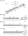
- Figs. 1(A), 1(B), 1(C), 1(D), and 1(E) and Figs. 2(A), 2(B), and 2(C) show an external appearance of a one-way damper mechanism 1.
- Figs. 3(A) and 3(B) show a state of an operation of the one-way damper mechanism 1.
- Figs. 4(A) and 4(B) show a schematic drawing in a state wherein the one-way damper mechanism 1 is attached to a glove box 2 of an automobile (omitted in the drawings).
- the one-way damper mechanism 1 comprises a long rack 10 wherein teeth are formed; a gear 20 engaged with the rack 10; a gear-holding member 30 comprising the gear 20 and relatively moving to the rack 10; a rotary damper 50 filled with a viscous fluid (omitted in the drawings) and the like; and a damper-holding member 60 comprising the rotary damper 50 and relatively moving to the rack 10.
- the rack 10 and the respective holding members 30 and 60 relatively move, so that as shown in Figs.
- the one-way damper mechanism 1 changes between a braking state (see Fig. 3(A) ) wherein the gear 20 and the rotary damper 50 are engaged, and a release state (see Fig. 3(B) ) wherein the gear 20 and the rotary damper 50 are separated.
- the rack 10 is supported by a glove box 2 as an oscillating member, and the damper-holding member 60 is supported by a support member 3 wherein the glove box 2 is supported and housed.
- the one-way damper mechanism 1 comes to the braking state when the glove box 2 opens (see Fig. 4(A) ), and comes to the release state when the glove box 2 is closed (see Fig. 4(B) ). Therefore, the glove box 2 opens slowly, and closes smoothly.
- a direction is defined as the standard of a case wherein the one-way damper mechanism 1 is used for the glove box 2. Namely, an opening portion side of the glove box 2 is upward; a bottom portion side of the glove box 2 is downward; a direction where the glove box 2 opens is frontward; a direction where the glove box 2 closes is backward; an inward direction of the glove box 2 is inward; and an outward direction is outward (see Fig. 2(A) and Fig. 4(A) ).
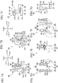
- Figs. 5(A), 5(B), 5(C), and 5(D) show the rack 10
- Figs. 6(A), 6(B), and 6(C) show the gear 20
- Figs. 7(A), 7(B), 7(C), 7(D), 7(E), 7(F), and 7(G) show the gear-holding member 30
- Figs. 8(A) and 8(B) show the rotary damper 50
- Figs. 9(A), 9(B), 9(C), 9(D), 9(E), and 9(F) and Figs. 10(A) and 10(B) show the damper-holding member 60.
- the rack 10 has a rod shape long in a front-back direction, and is formed in a flat plate shape.
- the rack 10 is formed by a rack-main member portion 11 which is a backward side, and a rack-support main member portion 15 which is a frontward side.
- a stopper 17 projecting outward from a backward end.
- the rack-main member portion 11 is divided into two upper and lower stages.
- the upper stage (the lower side in Fig. 5(B) ) is a sliding surface portion 12 formed flatly.
- the lower stage (the upper side in Fig.
- the rack-main member portion 11 On upper and lower surfaces and an inner surface of the rack-main member portion 11, there are respectively formed rack rail portions 14a, 14b, and 14c which are grooves continuing in the front-back direction.
- the rack-main member portion 11 may be a so-called angle rack or a round rack provided that the rack-main member portion 11 can form the sliding surface portion 12 or the rack rail portions 14a, 14b, and 14c.
- an oscillating-member support portion 16 approximately having a disk shape is formed inward.
- the gear 20 has a disk shape, and there are formed teeth on a circumferential edge.
- the gear 20 there is projected a gear-shaft portion 21 from a center.
- the gear-holding member 30 is formed by a gear-holding-member rail portion 31 through which the rack-main member portion 11 passes; a pair of gear-support portions 38 projecting outward from the gear-holding-member rail portion 31, and facing each other; and an elastic piece 47 as a sliding resistance portion projecting frontward from a boundary portion between the gear-holding-member rail portion 31 and the gear-support portion 38, and the respective portions 31, 38, and 47 are integrally molded.
- the gear-holding-member rail portion 31 is formed by a gear-holding-member inner surface portion 32; a gear-holding-member outer surface portion 33; a gear-holding-member upper surface portion 34; and a gear-holding-member lower surface portion 35, which are connected to each other in such a way so as to surround an outer surface of the rack-main member portion 11.
- an upper end of the gear-holding-member inner surface portion 32 and the gear-holding-member upper surface portion 34 are connected at right angles; the gear-holding-member upper surface portion 34 and the gear-holding-member outer surface portion 33 are connected at right angles; a lower end of the gear-holding-member inner surface portion 32 and the gear-holding-member lower surface portion 35 are connected at right angles; and a gear-holding-member hole portion 36 which is a space surrounded by the respective surface portions 32, 33, 34, and 35 opens in the front-back direction. Since the gear-holding-member outer surface portion 33 is formed shorter than the gear-holding-member inner surface portion 32, there is an opening between the gear-holding-member outer surface portion 33 and the gear-holding-member lower surface portion 35.
- gear-holding-member projecting portions 37a, 37b, and 37c toward the gear-holding-member hole portion 36.
- the elastic piece 47 projects frontward from an end of a frontward side. The elastic piece 47 inclines inward toward a gear-holding-member-hole-portion 36 side.
- the gear-support portion 38 is formed by a gear-holding-member upper facing portion 39 and a gear-holding-member lower facing portion 40, and gear-support holes 45 supporting the gear 20 are respectively formed.
- the gear-holding-member upper facing portion 39 is connected to a lower end of the gear-holding-member outer surface portion 33 at right angles, and a cylindrical shaft-supporting projecting portion 46, which is coaxial with the gear-support hole 45, projects.
- the gear-holding-member lower facing portion 40 is connected to the gear-holding-member lower surface portion 35 on the same one surface.
- a gear-holding-member contact portion 41 as a contact portion with the damper-holding member 60 is formed at a front end.
- the gear-holding-member contact portion 41 curves in an arc shape forward, and a foremost end portion 42, which is a small portion at the front end, is formed flatly. Incidentally, the foremost end portion 42 may be curved. Also, in the gear-holding-member contact portion 41, there is formed a flange portion 43. The flange portion 43 is formed in a peripheral edge over an outward side from the frontward side in the gear-holding-member lower facing portion 40, and projects downwardly. Also, in the gear-holding-member lower facing portion 40, there is formed a notch portion 44 close to a rear side of the outward side.
- the rotary damper 50 is formed by a case having an approximately cylindrical shape and filled with the viscous fluid; a rotor (omitted in the drawings) formed in a diameter approximately same as that of the case 51 and including a rotor shaft portion 52; a case lid 53 through which the rotor shaft portion 52 passes for covering the case 51; and a damper gear 54 attached to the rotor shaft portion 52.
- a case 51 there is housed the rotor, and in a state wherein the rotor shaft portion 52 is exposed to an outside of the case 51, the case 51 is closed by the case lid 53.
- the damper gear 54 on the same shaft as the rotor.
- the damper-holding member 60 is formed by a damper-holding-member inner surface portion 61; a damper-holding-member outer surface portion 62; a damper-holding-member upper surface portion 63; and a damper-holding-member lower surface portion 64, and the respective surface portions 61, 62, 63, and 64 are integrally molded, and are formed in a cylinder shape approximately with a square pole.
- a damper-holding-member hole portion 65 which is a space surrounded by the respective surface portions 61, 62, 63, and 64, opens in the front-back direction.
- a support-member support portion 66 on the outward side.
- a damper-housing hole 67 where the rotary damper 50 is housed, and damper-engagement pieces 68 formed around the damper-housing hole 67, where the rotary damper 50 engages.
- a long-hole frame portion 69 projects backward from a back end.
- movable areas 71a and 71b where the gear-holding member 30 is housed.
- damper-holding-member contact portions 72a and 72b as the contact portion with the gear-holding member 30 are respectively formed in the back end of the damper-holding-member lower surface portion 64 and a front end of the long-hole frame portion 69.
- damper-holding-member inner surface portion 61 there is formed a damper-holding-member projecting portion 73 toward the damper-holding-member hole portion 65. Also, in the damper-holding-member upper surface portion 63 and the damper-holding-member lower surface portion 64, there are formed inclined projecting portions 74a and 74b toward the damper-holding-member hole portion 65. In the inclined projecting portions 74a and 74b, a width of a front end thereof is formed narrower than a width of a back end thereof.
- the widths of the inclined projecting portions 74a and 74b are formed in such a way so as to become gradually narrow toward the front end from the back end, thereby a width of an inclined groove portion 75, which is a groove between the inclined projecting portions 74a and 74b and the damper-holding-member inner surface portion 61, is formed gradually wide toward the front end from the back end (see Figs. 10(A) and 10(B) ).
- the rotary damper 50 is attached to the damper-holding-member upper surface portion 63 of the damper-holding member 60.
- the damper gear 54 of the rotary damper 50 is housed in the damper-housing hole 67 of the damper-holding-member upper surface portion 63, and the case 51 of the rotary damper 50 engages the damper-engagement pieces 68 of the damper-holding-member upper surface portion 63.
- the damper gear 54 is disposed in the damper-holding-member hole portion 65.
- the damper-holding member 60 and the rotary damper 50 may be integrally molded as well.
- the gear-holding member 30 is attached to the damper-holding member 60.
- the shaft-supporting projecting portion 46 of the gear-holding member 30 is attached to the long-hole frame portion 69 of the damper-holding member 60
- the gear-holding-member contact portion 41 of the gear-holding member 30 is attached to the locking portion 70 of the damper-holding member 60.
- the gear-holding member 30 is disposed in the movable areas 71a and 71b of the damper-holding member 60.
- the rack 10 passes through the gear-holding member 30 and the damper-holding member 60.
- the rack-main member portion 11 passes through the damper-holding-member hole portion 65 of the damper-holding member 60 and a gear-holding-member hole portion 36 of the gear-holding member 30, respectively.
- the damper-holding-member projecting portion 73 of the damper-holding-member hole portion 65, the inclined projecting portions 74a and 74b, and the gear-holding-member projecting portions 37a, 37b, and 37c in the gear-holding-member hole portion 36 are respectively disposed in the rack rail portions 14a, 14b, and 14c.
- the elastic piece 47 of the gear-holding member 30 is pressed against the sliding surface portion 12 of the rack-main member portion 11.
- the gear 20 is attached to the gear-support portions 38 of the gear-holding member 30. Specifically explained, the gear 20 is disposed between the gear-support portions 38 from a backward side, and the gear-shaft portion 21 of the gear 20 is attached to the gear-support holes 45 of the gear-support portions 38. The gear 20 engages the tooth surface portion 13 of the rack-main member portion 11.
- FIG. 3(A) and 3(B) An operating state of the respective members 10, 30, and 60 in the one-way damper mechanism 1 assembled in the aforementioned manner will be explained based on Figs. 3(A) and 3(B) , Figs. 11(A), 11(B), and 11(C) , and Figs. 12(A) and 12(B) as follows.
- Figs. 11(A), 11(B), and 11(C) show a state wherein the rack 10 inclines relative to the damper-holding member 60 in the braking state
- Figs. 12(A) and 12(B) show the contact portion between the gear-holding member 30 and the damper-holding member 60 in the braking state.
- the respective holding members 30 and 60, and the rack 10 can move relatively in the front-back direction.
- the gear 20 and the damper gear 54 engage, so that the rotary damper 50 operates (see Fig. 3(A) ).
- the gear-holding member 30 is locked in the locking portion 70 of the notch portion 44, so that in the movable areas 71a and 71b of the damper-holding member 60, the gear-holding member 30 moves by following the damper-holding member 60 so as to control a movable range (see Fig. 3(B) )
- the rack 10 has a structure of inclining to the outward side which is a side wherein the tooth surface portion 13 is engaged with the gear 20, and inclining to an inward side which is a side opposite to the side wherein the tooth surface portion 13 is engaged with the gear 20, relative to the damper-holding member 60.
- the rack 10 since the width of the inclined groove portion 75 of the damper-holding member 60 is formed gradually wide toward the front end from the back end, the rack 10 inclines at a support point on a back end side where the width is narrow in the inclined groove portion 75.
- the one-way damper mechanism 1 changes according to a size between the glove box 2 and the support member 3, or an error of respective attachment holes within a range wherein sizes in the inward and outward sides are between X 2 and X 3 (see Figs. 4(A) and 4(B) ).
- the rack 10 inclines relative to the damper-holding member 60, so that the gear-holding member 30 inclines together with the rack 10 relative to the damper-holding member 60 as well. Since the gear-holding member 30 is stably attached relative to the rack 10, when the rack 10 inclines, the gear-holding member 30 and the damper-holding member 60 interfere in the respective gear-holding-member contact portion 41 and the damper-holding-member contact portions 72a and 72b, however, since a contact area is small, a degree of interferences is low.
- the gear-holding member 30 in the contact portion between the gear-holding member 30 and the damper-holding member 60 in the braking state, the gear-holding member 30 is formed smaller than the damper-holding member 60. Namely, while the damper-holding-member contact portion 72a of the damper-holding member 60 is flat, the gear-holding-member contact portion 41 of the gear-holding member 30 curves in the arc shape, so that an area of the foremost end portion 42 is formed smaller than that of the damper-holding-member contact portion 72a. In the movable area 71a, since the contact area is small, the gear-holding member 30 smoothly inclines relative to the damper-holding member 60 (see Fig. 12(B) ).
- damper gear 54 and the gear 20 are disposed in a position approximately the same as that of the respective contact portions 41 and 72a (see Figs. 3(A) and 3(B) ), when the gear-holding member 30 inclines relative to the damper-holding member 60, a state wherein both respective gears 54 and 20 engage is maintained.
- the damper-holding-member contact portion 72b is flat (see Figs. 9(A) and 9(D)
- the shaft-supporting projecting portion 46 of the gear-holding member 30 is cylindrical (see Figs. 7(A), 7(C), 7(D), and 7(F) ), so that the contact area is small in the movable area 71b as well.
- the one-way damper mechanism 1 comprises the gear 20 engaged with the rack 10 in the gear-holding member 30 which relatively moves to the rack 10; and the damper-holding member 60 wherein the rotary damper 50 is provided, which relatively moves to the rack 10. Namely, since the respective holding members 30 and 60 move stably along the rack 10, when the one-way damper mechanism 1 changes from the release state to the braking state, the gear 20 provided in the respective holding members 30 and 60, and the damper gear 54 of the rotary damper 50 appropriately engage so as to operate the rotary damper 50 properly, thereby reducing wobbling.
- the locking portion 70 projects from a side close to the damper-holding-member outer surface portion 62 in the back end of the damper-holding-member lower surface portion 64.
- the locking portion 70 extends backward, and a tip bends toward the inward side at a right angle to form a hook shape.
- the notch portion 44 of the gear-holding member 30 is locked in the locking portion 70, so that in the release state, a state wherein the gear-holding member 30 and the damper-holding member 60 are separated at a predetermined interval in the movable area 71a formed by the locking portion 70 is maintained.
- the gear-holding member 30 follows the damper-holding member 60. Therefore, the predetermined interval can be easily formed between the gear 20 and the damper gear 54.
- the elastic piece 47 projects frontward from a border portion between the gear-holding-member rail portion 31 and the gear-support portion 38, and the elastic piece 47 inclines inward toward the gear-holding-member-hole-portion 36 side.
- the elastic piece 47 is pressed against the sliding surface portion 12 of the rack-main member portion 11. Namely, the elastic piece 47 is pressed against the rack 10 so as to suppress the gear-holding member 30 from moving relative to the rack 10 by its own weight. Therefore, the gear 20 and the damper gear 54 appropriately engage so as to operate the rotary damper 50 properly.
- the gear-holding-member rail portion 31, the gear-support portion 38, and the elastic piece 47 are integrally molded. Therefore, an increase of number of the components is suppressed, and a structure including the elastic piece 47 can be provided.
- the width of the inclined groove portion 75 of the damper-holding member 60 is formed gradually wider toward the front end from the back end so as to have a structure such that the rack 10 inclines outward or inward relative to the damper-holding member 60.
- a size of the one-way damper mechanism 1 in the inward-outward side changes. Therefore, even in a case wherein there is an error in the size between the glove box 2 and the support member 3, or in the respective attachment holes, the one-way damper mechanism 1 can flexibly correspond to various sizes.
- the gear-holding member 30 in the contact portion between the gear-holding member 30 and the damper-holding member 60 in the braking state, the gear-holding member 30 is formed smaller than the damper-holding member 60. Namely, while the damper-holding-member contact portion 72a of the damper-holding member 30 is flat, the gear-holding-member contact portion 41 of the gear-holding member 30 curves in the arc shape, so that the area of the foremost end portion 42 is formed smaller than that of the damper-holding-member contact portion 72a. In the movable area 71a, since the contact area is small, the gear-holding member 30 smoothly inclines relative to the damper-holding member 60.
- the size of the one-way damper mechanism 1 in the inward side and the outward side easily changes, and even in the case wherein there is the error in the size between the glove box 2 and the support member 3, or in the respective attachment holes, the one-way damper mechanism 1 can flexibly correspond to the various sizes. Also, since the damper gear 54 and the gear 20 are disposed in the position approximately the same as that of the respective contact portions 41 and 72a, even in a case wherein the gear-holding member 30 inclines relative to the damper-holding member 60, a state wherein respective gears 54 and 20 engage reliably can be maintained.
- the rack 10 is supported by the glove box 2, and the damper-holding member 60 is supported by the support member 3.
- the gear 20 and the damper gear 54 provided in the respective holding members 30 and 60 engage appropriately so as to operate the rotary damper 50 properly.
- the glove box 2 is reliably braked in the braking state so as to be pulled out.
- the stopper 17 is formed at the backward end of the rack-main member portion 11. Therefore, the rack 10 can be prevented from slipping out of the gear-holding member 30 and the damper-holding member 60.
- the rack 10 is controlled by the stopper 17 so as not to slip out of the gear-holding member 30 and the damper-holding member 60.
- the locking portion is formed in the gear-holding member; the elastic piece is integrally molded with the damper-holding member; in place of the elastic piece, a soft material such as rubber or the like is sandwiched between the gear-holding member or the damper-holding member and the rack; an adhesive grease is coated; the stopper can be detachable relative to the rack; the rack inclines outward or inward relative to the gear-holding member; or in the contact portion, an area of the damper-holding-member contact portion is formed smaller than that of the gear-holding-member contact portion. Also, there may be provided a structure such that the damper-holding member 60 is supported by the glove box 2, and the rack 10 is supported by the support member 3.
- the damper gear 54 in the damper gear 54, only one side of a rotation shaft is supported by the rotor shaft portion 52, so that in the braking state, when an external force from the gear 20 acts on the damper gear 54, there is a possibility of a case wherein the damper gear 54 becomes decentered relative to the rotor shaft portion 52 and inclines. In that case, an engagement between the gear 20 and the damper gear 54 becomes inappropriate, so that there is a possibility of a case wherein abnormal noise occurs, or a case wherein the one-way damper mechanism 1 does not operate smoothly. Accordingly, the one-way damper mechanism according to a modified example of the present embodiment which solves the aforementioned problem will be explained based on the drawings. Figs.
- FIG. 13(A), 13(B), and 13(C) show an external appearance of a one-way damper mechanism 101, and a cross section of essential parts.
- Figs. 14(A) and 14(B) show a rotary damper 150 of the one-way damper mechanism 101
- Figs. 15(A) and 15(B) show a damper-holding member 160 of the one-way damper mechanism 101.
- structures same as those in the one-way damper mechanism 1 are designated by the same reference symbols, explanations thereof are omitted, and only structures different from the one-way damper mechanism 1 will be explained.
- the one-way damper mechanism 101 differs from the one-way damper mechanism 1 with regard to a structure of a damper gear 154 of the rotary damper 150, and a structure of a damper-holding-member lower surface portion 164 of the damper-holding member 160.
- a gear rib 155 in the damper gear 154, there is formed a gear rib 155.
- the gear rib 155 has approximately a "C" shape or an annular shape, is formed around a central axis of the damper gear 154, and projects in an axial direction.
- Figs. 13(A), 13(B), and 13(C) the one-way damper mechanism 101 differs from the one-way damper mechanism 1 with regard to a structure of a damper gear 154 of the rotary damper 150, and a structure of a damper-holding-member lower surface portion 164 of the damper-holding member 160.
- the gear rib 155 has approximately a "C" shape or an annular shape, is formed
- the holding-member rib 176 has an arc shape curved forward, faces the damper-housing hole 67 approximately on the same axis, and projects toward the damper-holding-member hole portion 65.
- the holding-member rib 176 may have approximately the "C" shape or the annular shape provided that a condition that the holding-member rib 176 does not interfere with the gear 20 is satisfied.
- the damper gear 154 is supported by the rotor shaft portion 52, and engages the holding-member rib 176, so that the damper gear 154 is supported on both sides in the rotation shaft.
- the damper gear 154 in the braking state, when the gear 20 and the damper gear 154 engage, and the external force from the gear 20 acts on the damper gear 154, the damper gear 154 stably rotates. Therefore, an engagement between the gear 20 and the damper gear 154 becomes appropriate, and the one-way damper mechanism 101 operates smoothly without the abnormal noise.
- tooth surface portions of the damper gear, the gear, and the rack are a helical tooth (omitted in the drawings)
- an engagement between the tooth surface portions of the damper gear, the gear, and the rack becomes appropriate further so as to provide a further smooth operation with low noise.
Applications Claiming Priority (2)
| Application Number | Priority Date | Filing Date | Title |
|---|---|---|---|
| JP2017071055 | 2017-03-31 | ||
| PCT/JP2018/013623 WO2018181905A1 (fr) | 2017-03-31 | 2018-03-30 | Mécanisme amortisseur unidirectionnel |
Publications (2)
| Publication Number | Publication Date |
|---|---|
| EP3604850A1 true EP3604850A1 (fr) | 2020-02-05 |
| EP3604850A4 EP3604850A4 (fr) | 2020-12-23 |
Family
ID=63678043
Family Applications (1)
| Application Number | Title | Priority Date | Filing Date |
|---|---|---|---|
| EP18775645.7A Pending EP3604850A4 (fr) | 2017-03-31 | 2018-03-30 | Mécanisme amortisseur unidirectionnel |
Country Status (6)
| Country | Link |
|---|---|
| US (1) | US11364849B2 (fr) |
| EP (1) | EP3604850A4 (fr) |
| JP (1) | JP6782356B2 (fr) |
| KR (1) | KR102075853B1 (fr) |
| CN (1) | CN110546398B (fr) |
| WO (1) | WO2018181905A1 (fr) |
Families Citing this family (8)
| Publication number | Priority date | Publication date | Assignee | Title |
|---|---|---|---|---|
| US10968678B2 (en) * | 2017-07-03 | 2021-04-06 | Hall Labs Llc | Automated sliding panel mechanism with manual release mechanism |
| DE102017213857A1 (de) * | 2017-08-09 | 2019-02-14 | Volkswagen Aktiengesellschaft | Gehäuse für ein Ablagefach, Befestigungssystem sowie Verfahren zum Herstellen eines Gehäuses für ein Ablagefach |
| US20200270919A1 (en) * | 2019-02-21 | 2020-08-27 | Marathonnorco Aerospace, Inc. | Hold Open Rod Having a Lock Mechanism for Securely Locking the Hold Open Rod in an Extended Configuration |
| CN113853470B (zh) * | 2019-05-28 | 2023-06-09 | 百乐仕株式会社 | 阻尼器装置 |
| WO2020241519A1 (fr) * | 2019-05-28 | 2020-12-03 | 株式会社パイオラックス | Dispositif amortisseur |
| DE102020117520A1 (de) * | 2020-07-02 | 2022-01-05 | Illinois Tool Works Inc. | Vorrichtung und verfahren zur geräuschminderung eines lineardämpfers |
| CN113432003B (zh) * | 2021-07-01 | 2023-04-25 | 金陵科技学院 | 一种摄影装置专用的电控滑动机构 |
| CN114987620B (zh) * | 2022-04-28 | 2023-06-23 | 南通浩盛汽车科技有限公司 | 一种用于汽车减震的多弹簧减震器 |
Family Cites Families (27)
| Publication number | Priority date | Publication date | Assignee | Title |
|---|---|---|---|---|
| JPS5836281B2 (ja) | 1973-05-10 | 1983-08-08 | 株式会社ニコン | コウデンテキニアラインメント オ オコナウ コウデンケンビキヨウ |
| JPS60101241U (ja) | 1983-12-16 | 1985-07-10 | シャープ株式会社 | スライダ機構用ダンパ機構 |
| JP3356887B2 (ja) | 1994-08-01 | 2002-12-16 | 株式会社ニフコ | 一方向性ダンパー機構 |
| US5690194A (en) * | 1995-10-30 | 1997-11-25 | Illinois Tool Works Inc. | One-way pivoting gear damper |
| US5839548A (en) * | 1995-10-30 | 1998-11-24 | Illinois Tool Works Inc. | Motion control device for rotary dampers |
| KR100353062B1 (ko) * | 1999-12-30 | 2002-09-18 | 현대자동차주식회사 | 회전체용 로타리 오일 댐퍼 구조 |
| AT412183B (de) * | 2001-01-25 | 2004-11-25 | Blum Gmbh Julius | Dämpfeinrichtung für bewegbare möbelteile |
| US6848759B2 (en) * | 2002-04-03 | 2005-02-01 | Illinois Tool Works Inc. | Self-closing slide mechanism with damping |
| DE602004000597D1 (de) * | 2003-07-31 | 2006-05-18 | Nifco Inc | Dämpfungsvorrichtung |
| JP2005048929A (ja) * | 2003-07-31 | 2005-02-24 | Nifco Inc | ダンパー機構 |
| KR20050048929A (ko) | 2003-11-20 | 2005-05-25 | 엘지.필립스 엘시디 주식회사 | 액정표시장치용 광학시트 |
| JP4424150B2 (ja) * | 2004-10-19 | 2010-03-03 | オイレス工業株式会社 | 自動車シート用のダンパ及びこのダンパを具備した自動車シート |
| US8079450B2 (en) * | 2005-11-14 | 2011-12-20 | Illinois Tool Works Inc. | Viscous strand damper assembly |
| JP2007145300A (ja) * | 2005-11-30 | 2007-06-14 | Toyoda Gosei Co Ltd | 収納体 |
| US20080224370A1 (en) * | 2007-03-14 | 2008-09-18 | Calvin Derr | Latching rack damper assembly |
| CN102112777B (zh) * | 2008-08-07 | 2014-12-03 | 伊利诺斯工具制品有限公司 | 粘滞带阻尼器组件 |
| DE102009042053A1 (de) * | 2009-09-08 | 2011-03-10 | Illinois Tool Works Inc., Glenview | Dämpfer |
| KR20110004218U (ko) * | 2009-10-22 | 2011-04-28 | 르노삼성자동차 주식회사 | 자동차의 글로브 박스 |
| KR101148717B1 (ko) * | 2010-08-13 | 2012-05-23 | 엘지엔시스(주) | 매체카세트 충격방지장치 |
| JP5836281B2 (ja) | 2010-11-24 | 2015-12-24 | 株式会社ニフコ | ダンパー装置 |
| JP5759207B2 (ja) * | 2011-03-02 | 2015-08-05 | 株式会社ニフコ | 回転ダンパ装置及びその製造方法 |
| JP2013204240A (ja) * | 2012-03-27 | 2013-10-07 | Nifco Inc | ラックユニットおよび移動体の移動機構 |
| JP6079885B2 (ja) * | 2013-08-09 | 2017-02-15 | 豊田合成株式会社 | グラブボックス |
| JP6227370B2 (ja) * | 2013-10-16 | 2017-11-08 | 株式会社ニフコ | ロック装置 |
| JP6570337B2 (ja) * | 2014-07-17 | 2019-09-04 | キヤノン株式会社 | 画像形成装置およびダンパ装置 |
| KR102211462B1 (ko) * | 2014-09-04 | 2021-02-03 | 현대모비스 주식회사 | 글로브박스 댐퍼 구조 |
| JP6448487B2 (ja) * | 2015-06-30 | 2019-01-09 | 日本発條株式会社 | 引戸制動装置及び引戸装置 |
-
2018
- 2018-03-30 WO PCT/JP2018/013623 patent/WO2018181905A1/fr active Application Filing
- 2018-03-30 KR KR1020187022869A patent/KR102075853B1/ko active IP Right Grant
- 2018-03-30 US US16/498,051 patent/US11364849B2/en active Active
- 2018-03-30 JP JP2019510251A patent/JP6782356B2/ja active Active
- 2018-03-30 CN CN201880022753.9A patent/CN110546398B/zh active Active
- 2018-03-30 EP EP18775645.7A patent/EP3604850A4/fr active Pending
Also Published As
| Publication number | Publication date |
|---|---|
| JP6782356B2 (ja) | 2020-11-11 |
| KR20190002421A (ko) | 2019-01-08 |
| WO2018181905A1 (fr) | 2018-10-04 |
| US20200317138A1 (en) | 2020-10-08 |
| US11364849B2 (en) | 2022-06-21 |
| CN110546398A (zh) | 2019-12-06 |
| EP3604850A4 (fr) | 2020-12-23 |
| CN110546398B (zh) | 2021-06-29 |
| KR102075853B1 (ko) | 2020-02-10 |
| JPWO2018181905A1 (ja) | 2019-11-07 |
Similar Documents
| Publication | Publication Date | Title |
|---|---|---|
| US11364849B2 (en) | One-way damper mechanism | |
| JP5666376B2 (ja) | ワンウェイクラッチ付き回転ダンパ装置 | |
| US20140097659A1 (en) | Recliner Mechanism Having a Brake | |
| US9475409B2 (en) | Seat recliner and oil collecting element | |
| JP6644447B2 (ja) | フラット型波動歯車装置 | |
| NZ616932A (en) | Improved winder assembly | |
| JP2021523846A (ja) | 乗物シート用リクライニング装置 | |
| JP6578384B2 (ja) | シートアジャスタ | |
| JP7133709B2 (ja) | ダンパー装置 | |
| JP6799944B2 (ja) | 遮蔽装置 | |
| JP5576820B2 (ja) | 魚釣用リール | |
| EP2839984A1 (fr) | Dispositif de réglage de portée angulaire et élément de collecte d'huile | |
| US9932061B2 (en) | Steering column assembly | |
| JP2016070026A (ja) | 自閉式引き戸の閉動作抑制構造 | |
| JP6911173B2 (ja) | シートリクライニング装置 | |
| TWI453348B (zh) | 阻尼器及使用此阻尼器的事務機 | |
| WO2020241519A1 (fr) | Dispositif amortisseur | |
| JP6541178B2 (ja) | 動力伝達装置および回転駆動装置 | |
| JPWO2011092730A1 (ja) | 表示機器 | |
| JP6045097B2 (ja) | ドアラッチの受け部材 | |
| WO2020026426A1 (fr) | Dispositif de verrouillage de capot pour véhicule | |
| JP2005074007A (ja) | リクライニング装置用シールドおよびこのシールドを備えた車両用シート | |
| JP2021042665A (ja) | 遮蔽装置 | |
| JP2011126295A (ja) | バスガイド用背あて | |
| WO2017126066A1 (fr) | Réducteur de vitesse et moteur équipé d'un réducteur de vitesse |
Legal Events
| Date | Code | Title | Description |
|---|---|---|---|
| STAA | Information on the status of an ep patent application or granted ep patent |
Free format text: STATUS: THE INTERNATIONAL PUBLICATION HAS BEEN MADE |
|
| PUAI | Public reference made under article 153(3) epc to a published international application that has entered the european phase |
Free format text: ORIGINAL CODE: 0009012 |
|
| STAA | Information on the status of an ep patent application or granted ep patent |
Free format text: STATUS: REQUEST FOR EXAMINATION WAS MADE |
|
| 17P | Request for examination filed |
Effective date: 20191011 |
|
| AK | Designated contracting states |
Kind code of ref document: A1 Designated state(s): AL AT BE BG CH CY CZ DE DK EE ES FI FR GB GR HR HU IE IS IT LI LT LU LV MC MK MT NL NO PL PT RO RS SE SI SK SM TR |
|
| AX | Request for extension of the european patent |
Extension state: BA ME |
|
| DAV | Request for validation of the european patent (deleted) | ||
| DAX | Request for extension of the european patent (deleted) | ||
| A4 | Supplementary search report drawn up and despatched |
Effective date: 20201124 |
|
| RIC1 | Information provided on ipc code assigned before grant |
Ipc: F16F 15/023 20060101ALI20201118BHEP Ipc: F16F 7/08 20060101ALI20201118BHEP Ipc: F16F 9/12 20060101ALI20201118BHEP Ipc: F16F 7/00 20060101AFI20201118BHEP Ipc: B60R 7/06 20060101ALI20201118BHEP Ipc: F16H 19/04 20060101ALI20201118BHEP Ipc: E05F 5/00 20170101ALI20201118BHEP Ipc: F16F 9/54 20060101ALI20201118BHEP |