WO2020241519A1 - Dispositif amortisseur - Google Patents
Dispositif amortisseur Download PDFInfo
- Publication number
- WO2020241519A1 WO2020241519A1 PCT/JP2020/020393 JP2020020393W WO2020241519A1 WO 2020241519 A1 WO2020241519 A1 WO 2020241519A1 JP 2020020393 W JP2020020393 W JP 2020020393W WO 2020241519 A1 WO2020241519 A1 WO 2020241519A1
- Authority
- WO
- WIPO (PCT)
- Prior art keywords
- pair
- damper
- case
- rack body
- side walls
- Prior art date
Links
Images


Classifications
-
- B—PERFORMING OPERATIONS; TRANSPORTING
- B60—VEHICLES IN GENERAL
- B60R—VEHICLES, VEHICLE FITTINGS, OR VEHICLE PARTS, NOT OTHERWISE PROVIDED FOR
- B60R7/00—Stowing or holding appliances inside vehicle primarily intended for personal property smaller than suit-cases, e.g. travelling articles, or maps
- B60R7/04—Stowing or holding appliances inside vehicle primarily intended for personal property smaller than suit-cases, e.g. travelling articles, or maps in driver or passenger space, e.g. using racks
- B60R7/06—Stowing or holding appliances inside vehicle primarily intended for personal property smaller than suit-cases, e.g. travelling articles, or maps in driver or passenger space, e.g. using racks mounted on or below dashboards
-
- F—MECHANICAL ENGINEERING; LIGHTING; HEATING; WEAPONS; BLASTING
- F16—ENGINEERING ELEMENTS AND UNITS; GENERAL MEASURES FOR PRODUCING AND MAINTAINING EFFECTIVE FUNCTIONING OF MACHINES OR INSTALLATIONS; THERMAL INSULATION IN GENERAL
- F16F—SPRINGS; SHOCK-ABSORBERS; MEANS FOR DAMPING VIBRATION
- F16F9/00—Springs, vibration-dampers, shock-absorbers, or similarly-constructed movement-dampers using a fluid or the equivalent as damping medium
- F16F9/10—Springs, vibration-dampers, shock-absorbers, or similarly-constructed movement-dampers using a fluid or the equivalent as damping medium using liquid only; using a fluid of which the nature is immaterial
- F16F9/12—Devices with one or more rotary vanes turning in the fluid any throttling effect being immaterial, i.e. damping by viscous shear effect only
-
- F—MECHANICAL ENGINEERING; LIGHTING; HEATING; WEAPONS; BLASTING
- F16—ENGINEERING ELEMENTS AND UNITS; GENERAL MEASURES FOR PRODUCING AND MAINTAINING EFFECTIVE FUNCTIONING OF MACHINES OR INSTALLATIONS; THERMAL INSULATION IN GENERAL
- F16H—GEARING
- F16H19/00—Gearings comprising essentially only toothed gears or friction members and not capable of conveying indefinitely-continuing rotary motion
- F16H19/02—Gearings comprising essentially only toothed gears or friction members and not capable of conveying indefinitely-continuing rotary motion for interconverting rotary or oscillating motion and reciprocating motion
- F16H19/04—Gearings comprising essentially only toothed gears or friction members and not capable of conveying indefinitely-continuing rotary motion for interconverting rotary or oscillating motion and reciprocating motion comprising a rack
Definitions
- the present invention relates to a damper device used for braking, for example, an opening / closing operation of an automobile glove box.
- a damper device may be used to prevent the lid from opening suddenly and to open it gently.
- a support having a substantially square frame shape, a rotary damper body rotatably supported in the support body, and a slidably arranged support body in the support body are provided.
- a damper device including a rack body that meshes with a pinion portion of a rotary damper body is described.
- Patent Document 2 describes a damper assembly including a base having a rack gear, a dolly that can operate relative to the base, and a damper that engages with the rack gear.
- the carriage comprises a plate-shaped main body, a circular container-shaped well portion connected to the main body and accommodating a damper rotatably, and a pair of followers erected from both sides of the main body.
- the base is composed of a long plate-shaped base plate and a pair of tracks hung from both sides on the long side. Then, the damper is pushed in the axial direction from the opening between the pair of followers of the bogie to be accommodated in the well part, and then the base is pushed against the bogie to insert the pair of trucks between the pair of followers. Then, a pair of trucks are sandwiched by a pair of followers, and a dolly is attached to the base.
- the rotary damper body and the rack body are inserted and arranged in the support body having a substantially square frame shape, and the support body has a shape that covers the rotary damper body and the rack body, so that the entire damper device is thick. Prone.
- an object of the present invention is to provide a damper device capable of narrowing the width of the rack body and reducing the thickness of the device.
- the present invention is a damper device that is attached between a pair of members that are close to each other and that are separated from each other, and applies a braking force when the pair of members are close to each other or separate from each other.
- a rotating damper that is connected to a fixed case, a rack body that is connected to the other member and is slidably supported by the case, and a rotating damper that is housed in the case and exerts a braking force when the rack body slides.
- the rack body has a substrate extending with a predetermined length, a pair of first side walls erected from facing portions of the substrate, and a pair of guides protruding from the outer surface of each first side wall.
- the case has a support wall that rotatably supports the rotary damper, a pair of second side walls erected from opposite portions of the support wall, and a pair of second side walls from the tip side to the inside. It has a pair of retaining portions that extend toward the guide rail and overlap the guide rail to prevent the rack body from coming off, and the pair of retaining portions are opposed to each other at the tip in the extending direction.
- the minimum distance between the surfaces is formed to be smaller than the maximum outer diameter of the rotating damper, and the substrate and / or a part of the first side wall is inserted into the region formed between the facing surfaces. It is characterized by being configured.
- the minimum distance between the facing surfaces of the pair of retaining portions is smaller than the maximum outer diameter of the rotary damper, the minimum distance between the facing surfaces of the pair of retaining portions is set as much as possible. It can be made smaller, whereby the width of the rack substrate can be made smaller and the damper device can be made narrower. Further, since the substrate and / or a part of the first side wall of the rack body enters the region formed between the facing surfaces of the pair of retaining portions, the rack body can be moved in the thickness direction of the pair of retaining portions.
- the damper devices can be made thinner by the amount of overlap.
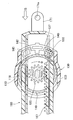
- FIG. 8 is a cross-sectional view taken along the line of sight of the arrow H in FIG. 8A. It is explanatory drawing which shows the state at the time of applying the braking force of the damper device. It is explanatory drawing which shows the state at the time of releasing the braking force of the damper device.
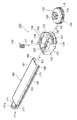
- the damper device 100 shown in FIG. 1 is attached to a pair of members that are close to each other and separate from each other, and applies a braking force when the pair of members are close to each other or separate from each other.
- the damper device 100 is applied to an instrument panel of an automobile. It can be used for braking, such as a glove box or a lid that can be opened and closed in the opening of the provided accommodating portion.
- one member is a fixed body such as an instrument panel accommodating portion, and the other member is attached to an opening of the fixed body so as to be openable and closable, such as a glove box or a lid.
- the pair of members is not particularly limited as long as they can be separated from each other.
- the damper device 100 of this embodiment has a case 130 fixed to one member and a rack body connected to the other member and slidably supported by the case 130.
- the rotary damper 110 which is housed in the case 130 and the case 130, exerts a braking force when the rack body 160 slides in one direction, and releases the braking force when the rack body 160 slides in the opposite direction to the one direction. It has a planetary gear 150 housed in the case 130.
- the rotary damper 110 includes a rotor 111 and a gear housing 115 that surrounds the rotor 111 with a viscous fluid and applies a braking force to the rotation of the rotor 111.
- the gear housing 115 has a recess 117 for accommodating the rotor 111 inside, and a large-diameter gear 116 having a gear formed on the outer periphery thereof and a cap 118 for sealing the opening of the recess 117 of the large-diameter gear 116.
- a shaft insertion hole 119 through which the shaft portion 112 provided in the rotor 111 is inserted is formed in the central portion of the cap 118. Further, as shown in FIG.
- An annular groove 123 is formed.
- the rotor 111 has a disk shape as a whole, a shaft portion 112 is projected from the central portion of one side thereof, and the shaft portion 112 is inserted into the shaft insertion hole 119 of the cap 118 via the seal ring 113 to form a gear housing. It protrudes to the outside of 115. Further, as shown in FIG. 9, a hemispherical protrusion 112a that can make point contact with the back surface of the substrate 161 described later of the rack body 160 is projected from the tip of the shaft portion 112. Further, as shown in FIG.
- the pinion gear 120 has a gear portion 121 on the outer periphery and a shaft hole 122 is formed in the central portion, and the shaft portion 112 is inserted into the shaft hole 122 and fixed to the shaft.
- the portion 112 and the pinion gear 120 rotate integrally.
- the pinion gear 120 rotates relative to the gear housing 115 via the shaft portion 112, so that the rotor 111 rotates with respect to the rotation of the rotor 111 via the viscous fluid. Braking force is applied.
- the pinion gear 120 is arranged between a pair of first side walls 163 and 163 (see FIG. 9) of the rack body 160, which will be described later, and as shown in FIG. It is adapted to mesh with the rack gear 167 formed on the inner surface of one side wall 163.
- the protrusion 112a is provided at the tip of the shaft portion 112. For example, the protrusion is projected from the center of the surface of the pinion gear 120, and the protrusion is brought into point contact with the back surface of the substrate of the rack body 160. It may be possible.
- the rack body 160 has a substrate 161 extending in a long plate shape with a predetermined length and a pair of first side walls 163 and 163 erected from opposite portions of the substrate 161.
- a pair of first side walls 163 and 163 are provided on both sides of the substrate 161 along the longitudinal direction), and the outer surface of each first side wall 163 projects from a position lowered from the surface of the substrate 161.
- It has a pair of guide rails 165 and 165, and a rack gear 167 formed on the inner surface of one of the first side walls 163.
- the rack gear 167 is formed on the inner surface side of one of the first side walls 163 along the longitudinal direction of the first side wall 163, and is a pinion gear mounted on the shaft portion 112 of the rotary damper 110. It is designed to mesh with 120. Therefore, when the rack body 160 slides with respect to the case 130, the pinion gear 120 meshing with the rack gear 167 rotates, and the rotor 111 rotates via the shaft portion 112.
- tapered surfaces 169 and 169 are formed at the connecting portions of the pair of guide rails 165 and 165 with the pair of first side walls 163 and 163, respectively.
- Each tapered surface 169 is the outer surface side of each guide rail 165 (the surface side of the case 130 facing the retaining portion 135 described later), and is directed from the outer edge portion side of each guide rail 165 toward the first side wall 163 side. Therefore, the rail is inclined so that the amount of protrusion gradually increases (see FIG. 9), and is formed over the entire longitudinal direction of the guide rail 165 (see FIG. 2).
- a pair of brackets 171 extend in parallel to one end of the rack body 160, and mounting holes 171a are formed in each bracket 171.
- a mounting shaft projecting from the side wall of the glove box is inserted into the mounting hole 171a so that one end of the rack body 160 can be mounted on a component such as the glove box to which braking force is to be applied.
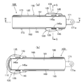
- a stopper portion 173 is projected from each portion of the rack body 160 close to one end portion in the longitudinal direction of the pair of guide rails 165 and 165. As shown in FIG. 8B, these stopper portions 173 and 173 are provided on the pair of second side walls 133 and 133 of the case 130 when the rack body 160 is pulled out with respect to the case 130. Further withdrawal of the rack body 160 is restricted by abutting on the stopper locking portions 134 and 134 (see FIGS. 5 and 7), respectively.
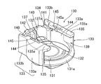
- the case 130 of this embodiment has a support wall 131 that rotatably supports the rotary damper 110, and a pair of second support walls 131 that are erected from opposite positions.
- the rack body 160 is extended inward from the side wall 133, 133 and the tip side of the pair of second side walls 133, 133 and overlaps with the pair of guide rails 165, 165 of the rack body 160.
- a pair of retaining portions 135, 135 for retaining the retaining portion and a pair of guide rail supporting walls 137 for supporting the pair of guide rails 165, 165 are provided between the pair of retaining portions 135, 135.
- the support wall 131 has a substantially circular shape corresponding to the shape of the rotary damper 110.
- a pair of arcuate ribs 132 and 132 are formed on the inner surface side of the support wall 131 (the support surface side of the rotary damper 110). Then, as shown in FIG. 10, these arcuate ribs 132 and 132 are fitted into the annular groove 123 formed on the bottom surface of the large diameter gear 116 of the rotary damper 110 to make the large diameter gear 116 rotatable. It has come to support.
- the pair of second side walls 133 and 133 are erected facing each other from both sides in the width direction of the support wall 131. As shown in FIG. 5, the pair of second side walls 133, 133 are erected in an arc shape, and the arc-shaped wall portions 133a and 133a whose ends are separated from each other and the arc-shaped wall portions 133a from the other end of the arc-shaped wall portions 133a. It is composed of extending wall portions 133b and 133b extending so as to be parallel to each other.
- One end side of the pair of second side walls 133, 133 that is, one end side of the arcuate wall portions 133a, 133a are separated from each other as described above, and a rotating damper 110 is placed between them on the side of the case 130.
- An opening 139 is provided so that it can be inserted from a direction (a direction orthogonal to the axial direction of the rotary damper 110).
- the height gradually protrudes toward the back side in the insertion direction of the rotary damper 110 with respect to the case 130.
- a guide surface 131a inclined so as to be high is provided. The guide surface 131a contributes to improving the workability of inserting the rotary damper 110 into the case 130.
- the guide rail support wall 137 is arranged on the other end side of the pair of second side walls 133 and 133 so as to face the opening 139. That is, as shown in FIGS. 5 and 6, the guide rail support wall 137 is arranged on the other end side of the extending wall portions 133b and 133b constituting the pair of second side walls 133 and 133, and the guide rail support wall 137 is arranged. Both extending wall portions 133b and 133b are connected to each other by a guide rail support wall 137. Further, as shown in FIG. 6, the guide rail support wall 137 is arranged so as to be separated from the outer periphery of the rotary damper 110 when the case 130 is viewed from the axial direction of the rotary damper 110.
- the guide rail support wall 137 has a length that does not reach the tip of the second side wall 133 in the vertical direction (the position where the retaining portion 135 is provided) from the inner surface side of the support wall 131. It is erected (here, the gear housing 115 of the rotary damper 110 is erected at a height that can be covered). As a result, as shown in FIG. 7, the rack body 160 can be inserted from the lateral direction of the case 130 between the upper end surface of the guide rail support wall 137 and the lower surface (inner surface) of the pair of retaining portions 135, 135.
- the rack insertion opening 141 is formed.
- a pair of support protrusions 137a and 137a are projected on the upper end surface of the guide rail support wall 137, and the pair of guide rails 165 and 165 of the rack body 160 are slid. It is supportable (see FIGS. 8 and 9).
- the back surface of the substrate 161 of the rack body 160 is supported by the protrusion 112a at the tip of the shaft portion 112 of the rotary damper 110, and the rack body 160 has the protrusion 112a and the pair of support protrusions 137a and 137a. So, it is supported by 3 points.
- FIG. 9 there is a clearance between the support protrusion 137a and the guide rail 165, but this is for convenience.
- stopper locking portions 134 and 134 which regulate the amount of the rack body 160 drawn out from the case 130, are projected, respectively.
- an engaging portion 142 is projected from the inner surface side of the guide rail support wall 137 in the width direction, and a pair of engaging portions 142 are interposed via the engaging portion 142.
- the accommodating portions 140 and 140 are defined between the second side walls 133 and 133.
- a planetary gear 150 meshing with the large diameter gear 116 of the rotary damper 110 is rotatably accommodated and arranged in one of the accommodating portions 140.
- the planetary gear 150 is restricted in rotation by engaging with the corner portion of the engaging portion 142, restricting the rotation of the large-diameter gear 116 (see FIG. 11), and is separated from the corner portion of the engaging portion 142. As a result, it becomes rotatable and allows the large-diameter gear 116 to rotate (see FIG. 12).
- the pair of retaining portions 135, 135 extend from the facing surfaces of the tips of the pair of second side walls 133, 133 in the erection direction so as to approach each other.
- the facing surfaces 135a and 135a located at the tip in the extending direction are extended so as to be parallel to each other.
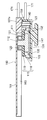
- the minimum distance L between the facing surfaces 135a and 135a of the pair of retaining portions 135 and 135 located at the tips in the extending direction (here, bullets described later).
- the protrusions 145a and 145a provided on the contact portions 145 and 145 are formed to be smaller than the maximum outer diameter R of the rotary damper 110 (here, the outer diameter of the large diameter gear 116), and the facing surface 135a is formed.
- 135a is configured so that a part of the substrate 161 and / or the first side wall 163 of the rack body 160 is inserted into the region E (see FIG. 7). As shown in FIG.
- the base end side of the pair of first side walls 163 and 163 is inserted into the region E between the facing surfaces 135a and 135a of the pair of retaining portions 135 and 135. It is configured. However, it may be configured so that only the substrate 161 is inserted between the pair of retaining portions 135 and 135, or both the substrate 161 and a part of the retaining portion 135 are inserted.
- the facing surfaces 135a and 135a of the pair of retaining portions 135 and 135 are provided in the region E (see FIG. 7) with the substrate 161 and / or the first of the rack body 160.
- a bullet contact portion 145 is provided that hits the tapered surface 169 of the rack body 160 when at least a part of the side wall 163 enters.
- the retaining portion 135 is directed from the portion closer to the other end of the second side wall 133 (the portion closer to the guide rail support wall 137) toward one end side of the second side wall 133.
- a slit 144 having a predetermined length is formed, and a bullet contact portion 145 that can be bent and deformed is provided through the slit 144. Further, a protrusion 145a is projected from the outer surface side (opposite surface 135a side) of the bullet contact portion 145 provided on one retaining portion 135 toward the other retaining portion 135.
- the elastic structure of the elastic portion is not particularly limited as long as the retaining portion may be made thin, in addition to forming a slit in the retaining portion.
- the rotary damper 110 is rotatably housed and arranged in the case 130, and the substrate 161 and / or the first of the rack body 160 is provided in the region E between the facing surfaces 135a and 135a of the pair of retaining portions 135 and 135.
- the protrusions 145a provided at the bullet contact portions 145 and 145 of the retaining portions 135 and 135. , 145a come into contact with the tapered surfaces 169 and 169 formed on the pair of guide rails 165 and 165, respectively.
- a hook 147 for attaching to a member giving a damper action is provided on the outer surface (lower surface) side of the support wall 131.
- the hook 147 when applied to a glove box, the hook 147 is attached to the side wall of the main body provided on the vehicle body side, and the bracket 171 of the rack body 160 is attached to the glove so as to be openable and closable. It is designed to be connected to the side wall of the box.
- the planetary gear 150 is placed on one of the accommodating portions 143 from the upper opening of the case 130.
- the rotary damper 110 is inserted from the lateral direction of the case 130 through the opening 139 on one end side of the pair of second side walls 133, 133, and is inserted into the inner surface of the support wall 131.
- the rotary damper 110 is rotationally supported in the case 130 so as not to shift laterally.
- the rack body 160 is inserted from the rack insertion opening 141 (see FIG. 7) formed between the guide rail support wall 137 and the pair of retaining portions 135 and 135. Insertion is performed from the lateral direction of the case 130 (that is, the insertion direction K1 of the rotary damper 110 into the case 130 and the insertion direction K2 of the rotary damper 110 into the case 130 are opposite to each other). Then, the rack body 160 is pushed in while the pair of guide rails 165 and 165 are supported by the pair of support protrusions 137a and 137a provided on the upper end surface of the guide rail support wall 137, and the pair of first side walls 163.
- the damper device 100 made of each component can be assembled.
- the planetary gear 150 may be mounted, and then the rack body 160 may be assembled so as to be slidable (K2 in FIG. 1).
- the order of K1 and K3) and the assembly procedure are not particularly limited.
- the minimum distance L between the facing surfaces 135a and 135a of the pair of retaining portions 135 and 135 (here, the protrusions provided at the bullet contact portions 145 and 145).
- the distance between the 145a and 145a is smaller than the maximum outer diameter R of the rotary damper 110 (here, the outer diameter of the large-diameter gear 116), and the region E (region E) formed between the facing surfaces 135a and 135a.
- a part of the substrate 161 and / or the first side wall 163 of the rack body 160 is inserted (here, the base end side of the pair of first side walls 163, 163 is inserted). ..
- the minimum distance L between the facing surfaces 135a and 135a of the pair of retaining portions 135 and 135 can be reduced as much as possible, whereby the width of the substrate 161 of the rack body 160 can be reduced and the damper device 100 can be reduced. Can be narrowed. Further, since the substrate 161 and / or a part of the first side wall 163 of the rack body 160 is configured to fit into the region E as shown in FIG. 7, the thickness of the pair of retaining portions 135 and 135 is thick. The rack bodies 160 overlap (wrap) in the direction, and the damper device 100 can be made thinner by that amount.
- the case 130 is provided with a guide rail support wall 137 for supporting the guide rail 165 between the case 130 and the retaining portion 135, and the guide rail support wall 137 is provided.
- the wall 137 is arranged so as to be separated from the outer periphery of the rotary damper 110 when the case 130 is viewed from the axial direction of the rotary damper 110. Therefore, the space inside the case 130 can be effectively utilized, and the guide rail support wall 137 can be provided while accommodating and arranging the rotary damper 110, thereby more effectively narrowing and thinning the damper device 100.
- the support wall 131 of the case 130 is separated from the pair of retaining portions 135 and 135 to lower the rotary damper 110.
- an opening 139 is provided on one end side of the pair of second side walls 133 and 133 so that the rotary damper 110 can be inserted.
- a guide rail support wall 137 is arranged on the other end side of the pair of second side walls 133 and 133, and is configured to connect the pair of second side walls 133 and 133 to each other. Therefore, the rotary damper 110 can be inserted through the opening 139 on one end side of the pair of second side walls 133 and 133 and housed in the case 130. Further, the rack body 160 can be inserted from the other end side of the pair of second side walls 133 and 133 while being supported by the guide rail support wall 137.
- the rotary damper 110 and the rack body 160 can be inserted and assembled from one end side and the other end side of the pair of second side walls 133, 133, respectively, so that the assembly workability of the damper device 100 is improved. be able to. Further, since the pair of second side walls 133 and 133 are connected to each other by the guide rail support wall 137 arranged on the other end side of the pair of second side walls 133 and 133, the rigidity of the pair of second side walls 133 and 133 is increased. Can be secured.
- the rotary damper 110 is provided with a protrusion 112a capable of making point contact with the back surface of the substrate 161. Therefore, as shown in FIG. 9, the rack body 160 has a pair of guide rails 165 and 165 supported by the guide rail support wall 137 (here, the rack body 160 projects from the upper end surface of the guide rail support wall 137). (Supported by a pair of support protrusions 137a and 137a), the back surface of the substrate 161 is supported by the protrusions 112a of the shaft portion 112 of the rotary damper 110 and supported by three points, so that the rack body 160 is loose. Can be slidably supported while reducing the amount of.
- the shaft is between the pair of first side walls 163 and 163 until the protrusion 112a contacts the back surface of the substrate 161.
- the portion 112 can be deeply inserted, and the pinion gear 120 and the rack gear 167 can be brought close to each other in the axial direction of the rotary damper 110, which contributes to the thinning of the damper device 100.
- tapered surfaces 169 and 169 are formed on the connecting portions of the pair of guide rails 165 and 165 with the pair of first side walls 163 and 163, respectively.
- the facing surfaces 135a and 135a of the pair of retaining portions 135 and 135 have the substrate 161 of the rack body 160 and / / in the region E as shown in FIG.
- the elastic contact portion 145 is provided so as to be in contact with the tapered surface 169 of the rack body 160 (pressed by the tapered surface 169 of the rack body 160 and flexed and deformed).
- a part of the reaction force is converted into a downward force as shown by arrow F2 by the tapered surface 169, and the rack body 160 is moved toward the rotating damper 110. Since it is pressed toward the rack, the backlash of the rack body 160 can be further reduced.
- this damper device 100 is mounted between a pair of parts that are close to each other and want to give a braking force.
- the hook 147 of the case 130 is connected to the side wall of the main body provided on the vehicle body side, and the bracket 171 is attached to the side wall of the glove box that opens and closes the main body. Are connected via the mounting holes 171a.
- the bracket 171 is located close to the case 130 as shown in FIG. 8A, and when the glove box is pulled out, the rack body 160 is pulled out with respect to the case 130.
- the stopper portion 173 comes into contact with the stopper locking portion 134 (see FIG. 5) of the case 130, further withdrawal is restricted.
- a braking force is applied by the rotary damper 110 to prevent the glove box from opening suddenly.
- the damper device 100 is used.
- the planetary gear 150 engages with the corner portion of the engaging portion 142, and the rotation of the planetary gear 150 is restricted. Therefore, the rotation of the large-diameter gear 116 is stopped, and only the rotor 111 rotates in the gear housing 115. It will be. Therefore, a braking force for the rotation of the rotor 111 is applied via the viscous fluid, and acts as a braking force for the movement of the rack body 160 in the arrow A direction. As a result, the glove box can be prevented from opening suddenly.
- the planetary gear 150 is allowed to rotate in the accommodating portion 140, the large-diameter gear 116 also rotates together with the rotor 111, and the braking force against the movement of the rack body 160 is released. As a result, the rack body 160 is pushed into the case 130 with less resistance, and the glove box can be quickly closed.
- the present invention is not limited to the above-described embodiments, and various modified embodiments are possible within the scope of the gist of the present invention, and such embodiments are also included in the scope of the present invention. ..
Abstract
La présente invention concerne un dispositif amortisseur dans lequel il est possible de réduire la largeur d'un corps de crémaillère et de rendre le dispositif plus fin. Le dispositif amortisseur (100) comprend un boîtier (130), un corps de crémaillère (160) et un amortisseur de rotation (110). Le corps de crémaillère (160) comprend un substrat (161), une paire de premières parois latérales (163, 163), une paire de rails de guidage (165, 165) et un engrenage à crémaillère (167). L'amortisseur de rotation (110) comporte un pignon (120). Le boîtier (130) a une paroi de support (131), une paire de secondes parois latérales (133, 133) et une paire de parties de retenue (135, 135). La distance minimale (L) entre la paire de parties de retenue (135, 135) est formée de manière à être inférieure au diamètre externe maximal (R) de l'amortisseur de rotation (110). Une partie du substrat (161) et/ou des premières parois latérales (163) est conçue de façon à entrer entre la paire de parties de retenue (135, 135).
Priority Applications (1)
| Application Number | Priority Date | Filing Date | Title |
|---|---|---|---|
| JP2021522327A JP7133710B2 (ja) | 2019-05-28 | 2020-05-22 | ダンパー装置 |
Applications Claiming Priority (2)
| Application Number | Priority Date | Filing Date | Title |
|---|---|---|---|
| JP2019-099441 | 2019-05-28 | ||
| JP2019099441 | 2019-05-28 |
Publications (1)
| Publication Number | Publication Date |
|---|---|
| WO2020241519A1 true WO2020241519A1 (fr) | 2020-12-03 |
Family
ID=73553437
Family Applications (1)
| Application Number | Title | Priority Date | Filing Date |
|---|---|---|---|
| PCT/JP2020/020393 WO2020241519A1 (fr) | 2019-05-28 | 2020-05-22 | Dispositif amortisseur |
Country Status (2)
| Country | Link |
|---|---|
| JP (1) | JP7133710B2 (fr) |
| WO (1) | WO2020241519A1 (fr) |
Citations (6)
| Publication number | Priority date | Publication date | Assignee | Title |
|---|---|---|---|---|
| JP2008163667A (ja) * | 2006-12-28 | 2008-07-17 | Nifco Inc | ダンパー装置 |
| JP2009516132A (ja) * | 2005-11-14 | 2009-04-16 | イリノイ トゥール ワークス インコーポレイティド | 粘性ストランドダンパー組立体 |
| JP2009203990A (ja) * | 2008-02-26 | 2009-09-10 | Piolax Inc | ダンパー装置 |
| WO2012070583A1 (fr) * | 2010-11-24 | 2012-05-31 | 株式会社ニフコ | Dispositif amortisseur |
| WO2012117654A1 (fr) * | 2011-03-02 | 2012-09-07 | 株式会社ニフコ | Dispositif amortisseur rotatif et son procédé de fabrication |
| WO2018181905A1 (fr) * | 2017-03-31 | 2018-10-04 | 株式会社ニフコ | Mécanisme amortisseur unidirectionnel |
-
2020
- 2020-05-22 WO PCT/JP2020/020393 patent/WO2020241519A1/fr active Application Filing
- 2020-05-22 JP JP2021522327A patent/JP7133710B2/ja active Active
Patent Citations (6)
| Publication number | Priority date | Publication date | Assignee | Title |
|---|---|---|---|---|
| JP2009516132A (ja) * | 2005-11-14 | 2009-04-16 | イリノイ トゥール ワークス インコーポレイティド | 粘性ストランドダンパー組立体 |
| JP2008163667A (ja) * | 2006-12-28 | 2008-07-17 | Nifco Inc | ダンパー装置 |
| JP2009203990A (ja) * | 2008-02-26 | 2009-09-10 | Piolax Inc | ダンパー装置 |
| WO2012070583A1 (fr) * | 2010-11-24 | 2012-05-31 | 株式会社ニフコ | Dispositif amortisseur |
| WO2012117654A1 (fr) * | 2011-03-02 | 2012-09-07 | 株式会社ニフコ | Dispositif amortisseur rotatif et son procédé de fabrication |
| WO2018181905A1 (fr) * | 2017-03-31 | 2018-10-04 | 株式会社ニフコ | Mécanisme amortisseur unidirectionnel |
Also Published As
| Publication number | Publication date |
|---|---|
| JPWO2020241519A1 (fr) | 2020-12-03 |
| JP7133710B2 (ja) | 2022-09-08 |
Similar Documents
| Publication | Publication Date | Title |
|---|---|---|
| JP6038136B2 (ja) | 開閉体のロック装置 | |
| WO2018181905A1 (fr) | Mécanisme amortisseur unidirectionnel | |
| EP2776652B1 (fr) | Ensemble d'amortisseur rotatif à auto-alignement | |
| US5195272A (en) | Lid switching device | |
| EP1659248B1 (fr) | Amortisseur flottant | |
| JP6467523B2 (ja) | 開閉体のロック装置 | |
| CN101677499A (zh) | 电子装置及其铰链结构 | |
| KR20180089409A (ko) | 개폐체의 잠금장치 | |
| JP2009280190A (ja) | トレイ装置 | |
| WO2020241519A1 (fr) | Dispositif amortisseur | |
| CN113853470B (zh) | 阻尼器装置 | |
| WO2022050177A1 (fr) | Dispositif de verrou de corps d'ouverture/de fermeture | |
| US10648215B2 (en) | Damper device for glove compartment | |
| KR200173283Y1 (ko) | 힌지 장치 | |
| JP3118012U (ja) | フラットパネルディスプレイモジュール | |
| JP2012085464A (ja) | コルゲートクランプ | |
| KR102603073B1 (ko) | 개폐체의 잠금 장치 | |
| GB2385653A (en) | A rotary damper and assist grip device incorporating such a rotary damper | |
| US20160250980A1 (en) | Roof molding cap attachment structure and roof molding | |
| JP4230436B2 (ja) | ダンパ付きヒンジ装置 | |
| JP7269372B2 (ja) | ロック解除装置 | |
| WO2021045066A1 (fr) | Dispositif d'amplification pour un corps d'ouverture/fermeture | |
| JPH0674277A (ja) | 開閉体の開閉動作支持機構 | |
| JPH036778Y2 (fr) | ||
| JP2008013088A (ja) | 車両用灰皿装置 |
Legal Events
| Date | Code | Title | Description |
|---|---|---|---|
| 121 | Ep: the epo has been informed by wipo that ep was designated in this application |
Ref document number: 20813235 Country of ref document: EP Kind code of ref document: A1 |
|
| ENP | Entry into the national phase |
Ref document number: 2021522327 Country of ref document: JP Kind code of ref document: A |
|
| NENP | Non-entry into the national phase |
Ref country code: DE |
|
| 122 | Ep: pct application non-entry in european phase |
Ref document number: 20813235 Country of ref document: EP Kind code of ref document: A1 |