EP3572198B1 - Coffrage central pour un système de coffrage destiné à bétonner un corps de cloche - Google Patents
Coffrage central pour un système de coffrage destiné à bétonner un corps de cloche Download PDFInfo
- Publication number
- EP3572198B1 EP3572198B1 EP18173984.8A EP18173984A EP3572198B1 EP 3572198 B1 EP3572198 B1 EP 3572198B1 EP 18173984 A EP18173984 A EP 18173984A EP 3572198 B1 EP3572198 B1 EP 3572198B1
- Authority
- EP
- European Patent Office
- Prior art keywords
- corner
- formwork
- connection panels
- supports
- formwork core
- Prior art date
- Legal status (The legal status is an assumption and is not a legal conclusion. Google has not performed a legal analysis and makes no representation as to the accuracy of the status listed.)
- Active
Links
Images


Classifications
-
- E—FIXED CONSTRUCTIONS
- E04—BUILDING
- E04G—SCAFFOLDING; FORMS; SHUTTERING; BUILDING IMPLEMENTS OR AIDS, OR THEIR USE; HANDLING BUILDING MATERIALS ON THE SITE; REPAIRING, BREAKING-UP OR OTHER WORK ON EXISTING BUILDINGS
- E04G11/00—Forms, shutterings, or falsework for making walls, floors, ceilings, or roofs
- E04G11/02—Forms, shutterings, or falsework for making walls, floors, ceilings, or roofs for rooms as a whole by which walls and floors are cast simultaneously, whole storeys, or whole buildings
-
- B—PERFORMING OPERATIONS; TRANSPORTING
- B28—WORKING CEMENT, CLAY, OR STONE
- B28B—SHAPING CLAY OR OTHER CERAMIC COMPOSITIONS; SHAPING SLAG; SHAPING MIXTURES CONTAINING CEMENTITIOUS MATERIAL, e.g. PLASTER
- B28B7/00—Moulds; Cores; Mandrels
- B28B7/02—Moulds with adjustable parts specially for modifying at will the dimensions or form of the moulded article
-
- B—PERFORMING OPERATIONS; TRANSPORTING
- B28—WORKING CEMENT, CLAY, OR STONE
- B28B—SHAPING CLAY OR OTHER CERAMIC COMPOSITIONS; SHAPING SLAG; SHAPING MIXTURES CONTAINING CEMENTITIOUS MATERIAL, e.g. PLASTER
- B28B7/00—Moulds; Cores; Mandrels
- B28B7/22—Moulds for making units for prefabricated buildings, i.e. units each comprising an important section of at least two limiting planes of a room or space, e.g. cells; Moulds for making prefabricated stair units
-
- B—PERFORMING OPERATIONS; TRANSPORTING
- B28—WORKING CEMENT, CLAY, OR STONE
- B28B—SHAPING CLAY OR OTHER CERAMIC COMPOSITIONS; SHAPING SLAG; SHAPING MIXTURES CONTAINING CEMENTITIOUS MATERIAL, e.g. PLASTER
- B28B7/00—Moulds; Cores; Mandrels
- B28B7/28—Cores; Mandrels
- B28B7/30—Cores; Mandrels adjustable, collapsible, or expanding
-
- E—FIXED CONSTRUCTIONS
- E04—BUILDING
- E04G—SCAFFOLDING; FORMS; SHUTTERING; BUILDING IMPLEMENTS OR AIDS, OR THEIR USE; HANDLING BUILDING MATERIALS ON THE SITE; REPAIRING, BREAKING-UP OR OTHER WORK ON EXISTING BUILDINGS
- E04G11/00—Forms, shutterings, or falsework for making walls, floors, ceilings, or roofs
- E04G11/06—Forms, shutterings, or falsework for making walls, floors, ceilings, or roofs for walls, e.g. curved end panels for wall shutterings; filler elements for wall shutterings; shutterings for vertical ducts
- E04G11/08—Forms, which are completely dismantled after setting of the concrete and re-built for next pouring
- E04G11/082—Retractable forms for the inside face of at least three walls
Definitions
- the present invention relates to a formwork core for a formwork system for concreting a bell body, in particular larger construction cells of residential buildings.
- Such a formwork system essentially consists of an outer formwork and the formwork core, which is generally cuboid and is inserted into the outer formwork.
- the outer formwork has a stationary formwork base as well as vertical longitudinal walls and end walls that stand up on a formwork base.
- the formwork core sits between the formwork walls of the outer formwork. Liquid concrete is pressed into the remaining space between the outer formwork and the formwork core. After the concrete has hardened, the outer formwork elements are removed. In order to detach the formwork core from the inner walls of the concreted bell body, the side formwork elements of the formwork core must be drawn inwards in order to be detached from the finished concrete part.
- shrink cores with inwardly retractable side formwork elements, so-called shrink cores, are known from the prior art.
- the European patent EP 2 083 977 B1 the applicant describes a formwork system for concreting room modules, comprising outer formwork and formwork core.
- the formwork core comprises a cover element, end elements and side elements as well as a coupling mechanism.
- the end elements and side elements are each coupled to the base and the cover element and are movably connected.
- the coupling mechanism is designed such that a vertical movement of a horizontal element causes a movement of the vertical elements in an inward direction such that the distance between the opposite vertical elements is reduced.
- the coupling mechanism comprises a plurality of pivot levers.
- DE 20 469 03 A1 describes a method for producing a bell body for larger building cells and a device for carrying out the method.
- One embodiment of the device comprises a stationary formwork core with columns and retractable side formwork.
- the side formworks are hinged to the pillars via several links.
- the mechanism of the pivoting causes the side formwork to fold back in such a way that wedge-shaped gaps are created between the walls of the finished concrete body and the formwork elements.
- EP 1 923 185 B1 describes a displacement body that is designed as a shrink body and can be pulled out of a side formwork after concreting.
- DE 25 04 218 A1 describes a formwork core for room cell formwork, which can be used as an inner shape for the production of a garage or a similar body.
- the formwork core has a variable cross-section.
- a game is provided between several pressure beams so that the cross section can be reduced in order to remove the formwork.
- DE 40 04 654 C1 discloses a formwork core for producing prefabricated garages or similar room cells from concrete.
- the formwork core can be adjusted in its width.
- the width can be adjusted using the Arrangement of formwork parts on slides that can be moved on rails.
- the total costs for a formwork system for concreting a bell body are therefore primarily determined by the costs for the complicated inner formwork core.
- the outer formwork elements required for concreting a cuboid bell body are in principle designed as flat formwork panels. Therefore, the outer formwork parts can be used again and again, even if a bell body with different dimensions, in particular larger or smaller width and / or length, is to be produced. It is sufficient to simply reassemble the flat formwork walls.
- a shrink core on the other hand, can only ever be used for a specific space cell with predetermined fixed dimensions in three dimensions. Due to the complex construction and the complicated adjustment mechanism, such a shrink core can only be dismantled into its individual parts with difficulty in order to reuse them for the production of a new formwork core with different dimensions. As a result, the conventional shrink cores are usually only used when a larger number of identical bell bodies are to be concreted, since the relatively high costs of the formwork core can then be allocated to the number of concrete parts produced.
- the object of the present invention is to create a formwork core with inwardly retractable side formwork elements, which can be changed quickly and easily so that it can be used for the production of bell bodies of different dimensions, in particular different widths and lengths.
- a formwork core according to the preamble of the first claim, comprising a base, vertical corner supports and side formwork elements which are suspended from the corner supports via pivot levers in such a way that the side formwork elements can be retracted inward.
- corner supports are releasably attached to a common base frame at a variable distance.
- the corner supports each carry two corner connection panels, which are arranged at right angles to one another and can be retracted and extended synchronously without touching one another.
- the corner connection panels have a flat outer wall that is designed as a formwork wall. When fully extended, a narrow vertical gap remains between the two corner connection panels in the area of the corner.
- the corner supports also each have a corner bracket that can be retracted and extended synchronously with the corner connection panels. In the fully extended state, this corner bracket closes the gap between the two associated corner connection panels and thereby forms a vertical outer edge of the formwork core.
- the vertical edges of the corner connection panels remote from the corner are designed in such a way that they can be detachably connected to one another.
- the resulting formwork core then has a minimum length or width. If necessary, one or, if necessary, several intermediate elements can be detachably inserted between the corner connection panels on one side. In this way, the width or length of the formwork core can be increased in a very simple manner, if a larger one Bell body is to be concreted. If necessary, the formwork core according to the invention can also be restored to its original dimensions by directly connecting the mutually facing vertical edges of the corner connection panels again.
- the formwork core designed according to the invention thus has the great advantage that it can be easily adapted to different dimensions of a bell body to be concreted without changing those elements that are structurally complex and therefore particularly expensive to manufacture.
- the corner supports, the corner connection panels movably mounted on the corner supports and the corner brackets can be used again and again, even if the hollow bodies to be concreted have very different dimensions.
- the corners of the formwork core are formed by two, in principle flat corner connection panels, which are arranged at right angles to each other across corners, and a corner bracket that closes the gap between the adjacent corner connection panels and forms the vertical outer edge of the formwork core.
- This construction has the advantage that the length of the corner connection panels can be varied easily. It is thus possible to very easily realize wider and shorter or narrower and longer formwork cores by simply using shorter or longer corner connection panels.
- the corner supports with their complex lever mechanisms and the attached corner brackets can in any case be used without modification.
- the corner connection panels In order to connect the vertical edges of the corner connection panels that are remote from the corner quickly and easily, but nevertheless firmly, and to detach them again later, the corner connection panels have inwardly facing screw flanges on the free edges. By means of these screw flanges, the corner connection panels on one side can either be directly detachably connected to one another or, alternatively, one or more extension parts can be attached.
- the corner brackets are preferably coupled to the corner connection panels in such a way that when the formwork core is pulled in, ie when the formwork core is shrunk, the corner brackets move inward in front of the corner connection panels. This moves the corner brackets out of the way before the associated corner connection panels are drawn inwards.
- the formwork core according to the invention is advantageously supplemented by a central ceiling panel that sits horizontally on the corner supports, with the corner connection panels and the associated corner brackets being coupled to the corner supports in such a way that when the formwork core is drawn in, the corner connection panels and the associated corner brackets inward and at the same time via the stationary Move the ceiling formwork panel upwards. It is true that the length and width of such a ceiling formwork panel can no longer be changed afterwards; However, since this formwork element is in principle a simple flat plate, any necessary replacement of the ceiling formwork as part of the reuse of the other, much more complex parts of the formwork core for concreting a bell body with different dimensions is hardly significant in terms of cost.
- the corner connection panels and the corner brackets expediently have ceiling webs on their upper edges that are set inwards at right angles. When the formwork core is fully extended, these ceiling webs, together with the central ceiling panel, form the top of the formwork core. When the shrinkage begins, the horizontal ceiling webs separate from the ceiling panel and move upwards and then inwards.
- the distance between two corner supports can be varied in that these corner supports are releasably fastened together on a base frame.
- This allows either the width or the length of the formwork core to be easily adjusted.
- the base frames have several parallel fastening grooves into which the fastening means, which are arranged at the foot of the corner supports, engage. This allows the two corner supports, which are attached to this base frame, to be moved continuously in order to vary the distance between the corner supports.
- the base frames comprise a number of T-beams arranged parallel and at a distance from one another. Each two adjacent T-beams form a fastening groove for fastening the corner supports.
- At least one side panel can be detachably inserted between two corner connection panels that form a side surface of the formwork core.
- the corner connection panels can be made very narrow, that is to say made very short in the horizontal direction; the length and / or the width of the formwork core is then essentially determined by the dimensions of the intermediate elements.
- corner connection panels not only the corner connection panels, but also the optionally usable side panel panels on their vertical edges have inwardly pointing screw flanges which correspond to the screw flanges of the corner connection parts. This enables a quick and detachable screw connection between corner connection panels and side panels.
- the formwork system according to Fig. 1a consists of a base plate 10, an outer formwork 20 and a formwork core 30, which is designed as a shrink core.
- the outer formwork 20 comprises two opposite end walls 21, two side walls 22 arranged at right angles thereto and a number of vertical outer supports 23 on which the end walls 21 and the side walls 22 are suspended.
- the outer supports 23 are releasably fastened in guide rails 24 so that all side formwork elements can be moved outwards after concreting.
- the formwork core 30 stands between the outer formwork 20.
- the bell-shaped concrete part (not shown) can be pulled out or pushed vertically upwards after it has hardened, whereby it detaches from the formwork core 30.
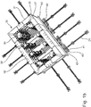
- the formwork core 30 has the shape of a rectangular parallelepiped, the underside of which is open. Its outer walls are formed by a total of eight corner connection panels 31, four between two corner connection panels 31 Inserted side formwork panels 32 and a central horizontal ceiling formwork panel 33 (cf. Fig. 1a, 1b ).
- Figure 1b allows a look into the interior of the formwork core 30.
- Four vertical corner supports 34 can be seen, each of which carries two corner connection panels 31. Two of the total of eight corner connection panels 31 are arranged at right angles to one another at a corner so that they enclose one of the four corners of the formwork core 30.
- the corner supports 34 also each have a corner bracket 35 which closes the gap between the two associated corner connection panels 31 and thus forms a vertical outer edge of the formwork core 30.
- two vertical side supports 36 are arranged along the two longitudinal sides of the formwork core 30. These side supports 36 carry the side formwork panels 32.
- the corner supports 34 and the side supports 36 are each detachably fastened in pairs on a common base frame 40.
- the distance between the corner supports 34 or side supports 36 mounted on a base frame 40 is variable, so that the width of the formwork core 30 can be adjusted.
- the base frames 40 have a number of upwardly open fastening grooves 41 arranged parallel to one another.
- the base frames 40 comprise a plurality of T-beams 42 which are arranged parallel and at a distance from one another and between which the fastening grooves 41 are formed. The ends of the T-beams 42 are screwed onto narrow cross beams 43, which are placed on the base plate 10 (cf. Fig. 1 ) rest.
- the guide rails 24 for the outer supports 23 protrude beyond the outer contour of the formwork core 30, so that the outer formwork 20 ( Fig. 1a ) can be moved far enough to the outside.
- a lifting frame 50 reaches under the lower edges of the formwork core 30. If this lifting frame 50 is moved upwards after the concrete has hardened, the (not shown) hardened concrete part of the outer walls of the formwork core 30; At the same time, the formwork core 30 shrinks in that the corner connection panels 31, the side panels 32 and the corner angle pieces 35 are drawn in in a synchronized manner. As a result, the outer sides of the formwork core detach from the concrete part.
- the corner brackets run forward.
- the kinematics can be driven electrically, hydraulically or purely mechanically.
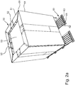
- Fig. 2a and the formwork core 50 shown in the following figures is somewhat smaller, in particular narrower and shorter than the previously described formwork core 30 according to FIG Fig. 1a , 1b .
- Both formwork cores 30 and 50 are constructed in the same way in principle.
- the smaller formwork core 50 is also designed as a shrink core.
- the side formwork elements of the formwork core 50 comprise a total of eight corner connection panels 51, four side formwork panels 52 arranged between them and a central, approximately square ceiling formwork panel 53. In Fig. 2a the side-form elements are raised a little bit upwards.
- the gap between the two corner connection panels 51 of a corner is filled by an elongated corner angle piece 55, which forms the vertical outer edge of the formwork core 50.
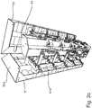
- the load-bearing structure of the formwork core 50 is formed in particular by four vertical corner supports 54, as from the Figures 2b , 2c and 2d is easy to see.
- Two of these corner supports 54 are releasably attached to a common base frame 60 ( Fig. 2a ).
- the corner supports 54 have at their lower end base plates 56 with fastening screws 56a inserted therein ( Fig. 2d ).
- the lower (not visible) ends of the fastening screws 56a engage in fastening grooves 61 of the base frame 60.
- the base frames 60 essentially consist of six T-beams 62, which are arranged parallel to one another and at some distance from one another, the ends of which are screwed onto transverse beams 63.
- the T-beams 62 form the fastening grooves 61 with a T-shaped profile. After loosening the fastening screws 56a, the corner supports 54 can be displaced longitudinally in the fastening grooves 61 in order in this way to increase or decrease the distance between the corner supports 54 and thus to change the length of the formwork core 50.
- the corner supports 54 each have two brackets 57 which are arranged at right angles to one another across corners. These holders 57 are articulated to the corner supports 54 by pivot levers 58. In a similar way, the corner brackets 55 are articulated to the corner supports 54 via lever arms 59 (cf. Figure 2b ). The corner connection panels 51 are mounted on the brackets 57 (cf. Figure 2c ).
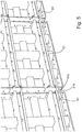
- FIG. 3 shows the upper end of a corner support 54.
- the corner support 54 has a hexagonal cross section.
- the pivot levers 58 for the corner connection panels 51 and the lever arm 59 for the corner angle piece 55 protrude outwards.
- the corner bracket 55 has moved inwards a little, so that a gap has arisen between the two adjoining corner connection panels 51 in the area of the corner. When the formwork core 50 is fully extended, this gap is of course closed.
- the adjacent corner connection panels 51 have already moved up a little here.
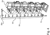
- Fig. 4 shows the cross-sectional profile of the corner angle pieces 55.
- the corner bracket 55 essentially consists of an elongated L-profile. At the upper end there is a ceiling web 55a which is attached at a right angle and points inward.
- the corner connection panels 51 have ceiling webs 51b attached to the inside at right angles ( Figure 2c , Fig. 3 ).
- the corner brackets 55 also have a ceiling web 55a attached at right angles inward at their upper end, as in particular in FIG Figures 2b and 4th is recognizable.
- the side panels 52 have ceiling webs 52b of the same length (cf. Figure 2c and Fig. 3 ).
- the corner angle pieces 55 are resiliently mounted at their lower ends on pressure plates 70 (cf. Fig. 4 ). As a result, the ceiling webs 55a of the corner brackets 55 can slide under the ceiling webs 52b of the adjoining corner connection panels 51 when the formwork core 50 is shrunk (cf. Fig. 3 , Fig. 2a , Figure 2b ).
- FIG. 2d shows the formwork core 50 in a state in which the corner connection panels 51 are still almost completely extended outwards, but the corner angle pieces 55 have already been pulled a little bit inwards or downwards.
- Figure 2b the corner connection panels 51 and the corner angle pieces 55 have moved a little further upwards, so that the way is free to now pull in the corner connection panels 51 further inwards. In doing so, they detach themselves from the walls (not shown) of the concreted bell body on the outside.
Claims (9)
- Noyau de coffrage destiné à un système de coffrage pour bétonner un corps de cloche, comportant une base, des supports d'angle verticaux et des éléments de coffrage latéraux, qui sont accrochés aux supports d'angle de manière oscillante de sorte que les éléments de coffrage latéraux peuvent être rétractés vers l'intérieur,
dans lequel
les supports d'angle (34, 54) portent respectivement deux panneaux de raccordement d'angle (31, 51), qui sont disposés en diagonal à angle droit et peuvent être rétractés et déployés de manière synchrone, sans se toucher, dans lequel, lorsqu'ils sont complètement déployés, un espace vertical étroit est ménagé entre les deux panneaux de raccordement d'angle dans la zone de l'angle ;
les supports d'angle portent chacun un coude d'angle (35, 55), qui peuvent être rétractés et déployés de manière synchrone et qui ferment lorsqu'ils sont complètement déployés l'espace ménagé entre les deux panneaux de raccordement d'angle associés (31,51), pour former un bord extérieur vertical du noyau de coffrage (30, 50) ;
les bords verticaux des panneaux de raccordement d'angle (31, 51), éloignés de l'angle, peuvent être reliés l'un à l'autre de manière amovible, caractérisé en ce que
à chaque fois deux supports d'angle (34, 54) sont fixés de manière amovible à un cadre de base commun (40, 60) à une distance variable. - Noyau de coffrage selon la revendication 1, caractérisé en ce que les panneaux de raccordement d'angle (31, 51) comportent des brides à vis tournées vers l'intérieur (52a) sur les bords verticaux éloignés de l'angle.
- Noyau de coffrage selon l'une des revendications précédentes, caractérisé en ce que les coudes d'angle (35, 55) sont couplés aux supports d'angle (34, 54) de sorte que lors de la rétractation les coudes d'angle rentrent vers l'intérieur devant les panneaux de raccordement d'angle.
- Noyau de coffrage selon l'une des revendications précédentes, caractérisé en ce qu'un panneau de coffrage de plafond horizontal (33, 53) est posé sur les supports d'angle (34, 54), et les panneaux de raccordement d'angle (31, 51) et les coudes d'angle associés (35,55) sont couplés avec les supports d'angle de sorte que lors de la rétractation du noyau de coffrage, les panneaux de raccordement d'angle et les coudes d'angle sortent vers le haut au-dessus du panneau de coffrage de plafond.
- Noyau de coffrage selon la revendication 4, caractérisé en ce que les panneaux de raccordement d'angle (31, 51) et les coudes d'angle (35, 55) comportent, sur leurs bords supérieurs, des entretoises de plafond (51b) fixées à angle droit vers l'intérieur et lorsque le noyau de coffrage est complètement déployé, ces entretoises de plafond et le panneau de coffrage de plafond (33, 51) central forment la face supérieure plane du noyau de coffrage.
- Noyau de coffrage selon l'une des revendications précédentes, caractérisé en ce que les cadres de base (40, 60) comportent plusieurs rainures de fixation parallèles (41, 61), dans lesquelles des moyens de fixation disposés au pied des supports d'angle (34, 54) viennent en prise.
- Noyau de coffrage selon la revendication 6, caractérisé en ce que les cadres de base (40, 60) comprennent un certain nombre de supports en T (42, 62) disposés parallèlement et de manière espacée les uns des autres.
- Noyau de coffrage selon l'une des revendications précédentes, caractérisé en ce qu'au moins un panneau de coffrage latéral (32, 52) peut être inséré à chaque fois entre les panneaux de raccordement d'angle (31, 51) qui forment une face latérale du noyau de coffrage (30, 50).
- Noyau de coffrage selon la revendication 8, caractérisé en ce que les panneaux de coffrage latéraux (32, 52) comportent, sur leurs bords verticaux, des brides à vis (52a) tournées vers l'intérieur, qui correspondent aux brides à vis (51a) des panneaux de raccordement d'angle (31, 51).
Priority Applications (7)
| Application Number | Priority Date | Filing Date | Title |
|---|---|---|---|
| ES18173984T ES2827191T3 (es) | 2018-05-24 | 2018-05-24 | Núcleo de encofrado para un sistema de encofrado para hormigonar un cuerpo de campana |
| EP18173984.8A EP3572198B1 (fr) | 2018-05-24 | 2018-05-24 | Coffrage central pour un système de coffrage destiné à bétonner un corps de cloche |
| SG11202011526QA SG11202011526QA (en) | 2018-05-24 | 2019-04-12 | Formwork core for a formwork system for casting a bell-shaped body |
| MX2020012191A MX2020012191A (es) | 2018-05-24 | 2019-04-12 | Núcleo de encofrado para un sistema de encofrado para hormigonar un cuerpo de campana. |
| US17/052,659 US20210238870A1 (en) | 2018-05-24 | 2019-04-12 | Formwork core for a formwork system for casting a bell-shaped body |
| PCT/EP2019/059453 WO2019223936A1 (fr) | 2018-05-24 | 2019-04-12 | Noyau de coffrage pour système de coffrage permettant de bétonner un corps de cloche |
| PH12020551977A PH12020551977A1 (en) | 2018-05-24 | 2020-11-19 | Formwork core for a formwork system for concreting a bell body |
Applications Claiming Priority (1)
| Application Number | Priority Date | Filing Date | Title |
|---|---|---|---|
| EP18173984.8A EP3572198B1 (fr) | 2018-05-24 | 2018-05-24 | Coffrage central pour un système de coffrage destiné à bétonner un corps de cloche |
Publications (2)
| Publication Number | Publication Date |
|---|---|
| EP3572198A1 EP3572198A1 (fr) | 2019-11-27 |
| EP3572198B1 true EP3572198B1 (fr) | 2020-09-23 |
Family
ID=62455336
Family Applications (1)
| Application Number | Title | Priority Date | Filing Date |
|---|---|---|---|
| EP18173984.8A Active EP3572198B1 (fr) | 2018-05-24 | 2018-05-24 | Coffrage central pour un système de coffrage destiné à bétonner un corps de cloche |
Country Status (7)
| Country | Link |
|---|---|
| US (1) | US20210238870A1 (fr) |
| EP (1) | EP3572198B1 (fr) |
| ES (1) | ES2827191T3 (fr) |
| MX (1) | MX2020012191A (fr) |
| PH (1) | PH12020551977A1 (fr) |
| SG (1) | SG11202011526QA (fr) |
| WO (1) | WO2019223936A1 (fr) |
Families Citing this family (5)
| Publication number | Priority date | Publication date | Assignee | Title |
|---|---|---|---|---|
| CN113931333A (zh) * | 2021-11-02 | 2022-01-14 | 山东海瑞林装饰工程有限公司 | 一种外墙保温板及其生产方法 |
| CN114102816B (zh) * | 2021-11-19 | 2022-12-02 | 长安大学 | 一种多边形预制薄壳三维结构模块化模具 |
| CN115012645B (zh) * | 2022-06-29 | 2023-03-24 | 涿州天保建筑体系有限公司 | 墙体模板、建筑墙体及建筑墙体的施工方法 |
| CN115306140A (zh) * | 2022-09-15 | 2022-11-08 | 中建七局第一建筑有限公司 | 一种建筑铝模板插扣式装配构造及安装施工方法 |
| CN117381952B (zh) * | 2023-12-08 | 2024-02-23 | 山西建投建筑产业有限公司 | 一种叠合板模具及加固装置 |
Family Cites Families (12)
| Publication number | Priority date | Publication date | Assignee | Title |
|---|---|---|---|---|
| DE2046903C3 (de) | 1970-09-23 | 1979-09-13 | Fa. Werner Zapf, Vorm. Adam Zapf, 8580 Bayreuth | Kastenförmige Innenschalung zum serienmäßigen Herstellen von Raumzellen |
| DE2504218C3 (de) | 1975-02-01 | 1982-08-26 | Gärtner, Franz, 7505 Ettlingen | Schalungskern zum Herstellen von raumgroßen Baukörpern, wie Raumzellen, aus Beton o.dgl. |
| DE2812974A1 (de) * | 1978-03-23 | 1979-10-04 | Schoenwald Ag | Verschalungseinheit fuer schalungen zur verwendung fuer die errichtung von bauwerken |
| US4570896A (en) * | 1984-02-06 | 1986-02-18 | Strickland Systems, Inc. | Slide action inside corner form |
| US4650150A (en) * | 1985-04-19 | 1987-03-17 | Opako, S.A. | Mold apparatus for vertical elements of concrete |
| DE4004654C1 (en) | 1990-02-15 | 1991-05-29 | Hochtief Ag Vorm. Gebr. Helfmann, 4300 Essen, De | Formwork core for garage - has overlapping skins for roof and rear wall with staging |
| US5524861A (en) * | 1994-04-22 | 1996-06-11 | Modal Systems, Inc. | Reusable mold for constructing housing units and method of use thereof |
| US5755982A (en) * | 1994-11-07 | 1998-05-26 | Strickland Industries, Inc. | Concrete casting system |
| ES2281212B1 (es) * | 2002-11-18 | 2008-08-16 | Sistemas Industrializados Barcons, S.L. | Perfeccionamientos en los sistemas de construccion de estructuras de hormigon armado u otro material mediante encofrados modulares e integrales de alta precision. |
| EP1923185B1 (fr) | 2006-11-15 | 2014-08-27 | Ratec Maschinenentwicklungs- und Verwaltungs-GmbH | Méthode et dispositif de fabrication d'un élément monobloc préfabriqué en béton |
| WO2010091452A1 (fr) * | 2009-02-10 | 2010-08-19 | Precast Modular Solutions Pty Ltd | Agencement de construction de bâtiment modulaire |
| DE102009055690A1 (de) * | 2009-11-25 | 2011-05-26 | Peri Gmbh | Ausschalvorrichtung |
-
2018
- 2018-05-24 EP EP18173984.8A patent/EP3572198B1/fr active Active
- 2018-05-24 ES ES18173984T patent/ES2827191T3/es active Active
-
2019
- 2019-04-12 SG SG11202011526QA patent/SG11202011526QA/en unknown
- 2019-04-12 WO PCT/EP2019/059453 patent/WO2019223936A1/fr active Application Filing
- 2019-04-12 US US17/052,659 patent/US20210238870A1/en active Pending
- 2019-04-12 MX MX2020012191A patent/MX2020012191A/es unknown
-
2020
- 2020-11-19 PH PH12020551977A patent/PH12020551977A1/en unknown
Non-Patent Citations (1)
| Title |
|---|
| None * |
Also Published As
| Publication number | Publication date |
|---|---|
| US20210238870A1 (en) | 2021-08-05 |
| MX2020012191A (es) | 2022-02-15 |
| EP3572198A1 (fr) | 2019-11-27 |
| SG11202011526QA (en) | 2020-12-30 |
| ES2827191T3 (es) | 2021-05-20 |
| WO2019223936A1 (fr) | 2019-11-28 |
| PH12020551977A1 (en) | 2021-09-13 |
Similar Documents
| Publication | Publication Date | Title |
|---|---|---|
| EP3572198B1 (fr) | Coffrage central pour un système de coffrage destiné à bétonner un corps de cloche | |
| DE2229264C2 (de) | Verfahren zur fabrikmäßigen Herstellung der Geschosse eines Gebäudes und Vorrichtung zur Ausführung des Verfahrens | |
| EP2083977B1 (fr) | Système de coffrage pour le bétonnage d'éléments préfabriqués, comprenant un coffrage extérieur et un coffrage central | |
| DE102015113077B4 (de) | Schalform für ein Bauelement und Verfahren zum Ausschalen | |
| EP2910687A1 (fr) | Dispositif et procédé de fabrication d'un tunnel présentant plusieurs tronçons de tunnel | |
| DE2534160A1 (de) | Schalung zum betonieren | |
| DE1759214B2 (de) | Vorrichtung zur serienmaessigen herstellung von einseitig offenen raumzellen aus stahlbeton | |
| EP1347120B1 (fr) | Dispositif de coffrage et de décoffrage | |
| CH640774A5 (en) | Shaping table for prefabricated concrete slabs | |
| WO2014020009A1 (fr) | Dispositif de fabrication d'une cellule préfabriquée dans une construction monolithique | |
| DE2122874A1 (de) | Verfahren und Vorrichtung zum Herstellen dreidimensionaler, aus Beton oder dgl. geformter Bauelemente | |
| DE2400790C2 (de) | Verfahren und Vorrichtung zur Herstellung von Raumzellen aus Stahlbeton, z.B. Fertiggaragen | |
| DE2417805C2 (de) | Schalungskern zur Herstellung von einseitig offenen Raumzellen aus Stahlbeton | |
| DE880057C (de) | Stahlschalung zur Herstellung glatter geschuetteter Waende | |
| EP3529020B1 (fr) | Dispositif et procédé pour produire d'un seul tenant un module formant un espace, lequel module présente trois éléments latéraux et un élément formant le fond et/ou le couvercle. | |
| DE2531284A1 (de) | Schalung zur herstellung von insbesondere fuenfseitig geschlossenen, vorzugsweise quaderfoermigen und monolithischen raumzellen aus stahlbeton | |
| EP0480295B1 (fr) | Ensemble pour la construction d'une maison d'habitation ou de vacances | |
| CH713190A2 (de) | Vorrichtung und Verfahren zur Verbindung von zwei Bauteilen in einer bestimmten relativen Ausrichtung sowie damit erstelltes Betonbauwerk. | |
| DE2128548C3 (de) | Vorrichtung zum punktweisen Auflagern vorgefertigter Spannbetonplatten. < | |
| DE10016978B4 (de) | Vorrichtung zum Herstellen von Raumzellen aus Beton | |
| DE2115553B2 (de) | Schalung zum serienmäßigen Herstellen von Raumzellen aus Beton mit unterschiedlichen lichten Breiten | |
| DE938987C (de) | Vorrichtung zur Herstellung von Bauwerken, insbesondere von Mauerwerken aus Schuettbeton u. dgl. | |
| DE2033514A1 (de) | Verfahren und Einrichtung zum Bau von Räumen, insbesondere fur den Wohngebrauch | |
| EP3832052A1 (fr) | Coffrage pour generer une porte ou fenetre dans un mur ou dalle en beton | |
| DE2711116A1 (de) | Schalung zur herstellung von raumzellen, wie fertiggaragen o.dgl. |
Legal Events
| Date | Code | Title | Description |
|---|---|---|---|
| PUAI | Public reference made under article 153(3) epc to a published international application that has entered the european phase |
Free format text: ORIGINAL CODE: 0009012 |
|
| STAA | Information on the status of an ep patent application or granted ep patent |
Free format text: STATUS: THE APPLICATION HAS BEEN PUBLISHED |
|
| AK | Designated contracting states |
Kind code of ref document: A1 Designated state(s): AL AT BE BG CH CY CZ DE DK EE ES FI FR GB GR HR HU IE IS IT LI LT LU LV MC MK MT NL NO PL PT RO RS SE SI SK SM TR |
|
| AX | Request for extension of the european patent |
Extension state: BA ME |
|
| STAA | Information on the status of an ep patent application or granted ep patent |
Free format text: STATUS: REQUEST FOR EXAMINATION WAS MADE |
|
| GRAP | Despatch of communication of intention to grant a patent |
Free format text: ORIGINAL CODE: EPIDOSNIGR1 |
|
| STAA | Information on the status of an ep patent application or granted ep patent |
Free format text: STATUS: GRANT OF PATENT IS INTENDED |
|
| 17P | Request for examination filed |
Effective date: 20200116 |
|
| RBV | Designated contracting states (corrected) |
Designated state(s): AL AT BE BG CH CY CZ DE DK EE ES FI FR GB GR HR HU IE IS IT LI LT LU LV MC MK MT NL NO PL PT RO RS SE SI SK SM TR |
|
| INTG | Intention to grant announced |
Effective date: 20200210 |
|
| GRAS | Grant fee paid |
Free format text: ORIGINAL CODE: EPIDOSNIGR3 |
|
| GRAA | (expected) grant |
Free format text: ORIGINAL CODE: 0009210 |
|
| STAA | Information on the status of an ep patent application or granted ep patent |
Free format text: STATUS: THE PATENT HAS BEEN GRANTED |
|
| AK | Designated contracting states |
Kind code of ref document: B1 Designated state(s): AL AT BE BG CH CY CZ DE DK EE ES FI FR GB GR HR HU IE IS IT LI LT LU LV MC MK MT NL NO PL PT RO RS SE SI SK SM TR |
|
| REG | Reference to a national code |
Ref country code: GB Ref legal event code: FG4D Free format text: NOT ENGLISH |
|
| REG | Reference to a national code |
Ref country code: CH Ref legal event code: EP |
|
| REG | Reference to a national code |
Ref country code: IE Ref legal event code: FG4D Free format text: LANGUAGE OF EP DOCUMENT: GERMAN |
|
| REG | Reference to a national code |
Ref country code: DE Ref legal event code: R096 Ref document number: 502018002518 Country of ref document: DE Ref country code: AT Ref legal event code: REF Ref document number: 1315936 Country of ref document: AT Kind code of ref document: T Effective date: 20201015 |
|
| REG | Reference to a national code |
Ref country code: NL Ref legal event code: FP |
|
| REG | Reference to a national code |
Ref country code: FI Ref legal event code: FGE |
|
| REG | Reference to a national code |
Ref country code: CH Ref legal event code: NV Representative=s name: ISLER AND PEDRAZZINI AG, CH |
|
| PG25 | Lapsed in a contracting state [announced via postgrant information from national office to epo] |
Ref country code: GR Free format text: LAPSE BECAUSE OF FAILURE TO SUBMIT A TRANSLATION OF THE DESCRIPTION OR TO PAY THE FEE WITHIN THE PRESCRIBED TIME-LIMIT Effective date: 20201224 Ref country code: NO Free format text: LAPSE BECAUSE OF FAILURE TO SUBMIT A TRANSLATION OF THE DESCRIPTION OR TO PAY THE FEE WITHIN THE PRESCRIBED TIME-LIMIT Effective date: 20201223 Ref country code: BG Free format text: LAPSE BECAUSE OF FAILURE TO SUBMIT A TRANSLATION OF THE DESCRIPTION OR TO PAY THE FEE WITHIN THE PRESCRIBED TIME-LIMIT Effective date: 20201223 Ref country code: SE Free format text: LAPSE BECAUSE OF FAILURE TO SUBMIT A TRANSLATION OF THE DESCRIPTION OR TO PAY THE FEE WITHIN THE PRESCRIBED TIME-LIMIT Effective date: 20200923 Ref country code: HR Free format text: LAPSE BECAUSE OF FAILURE TO SUBMIT A TRANSLATION OF THE DESCRIPTION OR TO PAY THE FEE WITHIN THE PRESCRIBED TIME-LIMIT Effective date: 20200923 |
|
| PG25 | Lapsed in a contracting state [announced via postgrant information from national office to epo] |
Ref country code: LV Free format text: LAPSE BECAUSE OF FAILURE TO SUBMIT A TRANSLATION OF THE DESCRIPTION OR TO PAY THE FEE WITHIN THE PRESCRIBED TIME-LIMIT Effective date: 20200923 Ref country code: RS Free format text: LAPSE BECAUSE OF FAILURE TO SUBMIT A TRANSLATION OF THE DESCRIPTION OR TO PAY THE FEE WITHIN THE PRESCRIBED TIME-LIMIT Effective date: 20200923 |
|
| REG | Reference to a national code |
Ref country code: LT Ref legal event code: MG4D |
|
| PG25 | Lapsed in a contracting state [announced via postgrant information from national office to epo] |
Ref country code: SM Free format text: LAPSE BECAUSE OF FAILURE TO SUBMIT A TRANSLATION OF THE DESCRIPTION OR TO PAY THE FEE WITHIN THE PRESCRIBED TIME-LIMIT Effective date: 20200923 Ref country code: LT Free format text: LAPSE BECAUSE OF FAILURE TO SUBMIT A TRANSLATION OF THE DESCRIPTION OR TO PAY THE FEE WITHIN THE PRESCRIBED TIME-LIMIT Effective date: 20200923 Ref country code: CZ Free format text: LAPSE BECAUSE OF FAILURE TO SUBMIT A TRANSLATION OF THE DESCRIPTION OR TO PAY THE FEE WITHIN THE PRESCRIBED TIME-LIMIT Effective date: 20200923 Ref country code: RO Free format text: LAPSE BECAUSE OF FAILURE TO SUBMIT A TRANSLATION OF THE DESCRIPTION OR TO PAY THE FEE WITHIN THE PRESCRIBED TIME-LIMIT Effective date: 20200923 Ref country code: PT Free format text: LAPSE BECAUSE OF FAILURE TO SUBMIT A TRANSLATION OF THE DESCRIPTION OR TO PAY THE FEE WITHIN THE PRESCRIBED TIME-LIMIT Effective date: 20210125 Ref country code: EE Free format text: LAPSE BECAUSE OF FAILURE TO SUBMIT A TRANSLATION OF THE DESCRIPTION OR TO PAY THE FEE WITHIN THE PRESCRIBED TIME-LIMIT Effective date: 20200923 |
|
| REG | Reference to a national code |
Ref country code: ES Ref legal event code: FG2A Ref document number: 2827191 Country of ref document: ES Kind code of ref document: T3 Effective date: 20210520 |
|
| PG25 | Lapsed in a contracting state [announced via postgrant information from national office to epo] |
Ref country code: AL Free format text: LAPSE BECAUSE OF FAILURE TO SUBMIT A TRANSLATION OF THE DESCRIPTION OR TO PAY THE FEE WITHIN THE PRESCRIBED TIME-LIMIT Effective date: 20200923 Ref country code: IS Free format text: LAPSE BECAUSE OF FAILURE TO SUBMIT A TRANSLATION OF THE DESCRIPTION OR TO PAY THE FEE WITHIN THE PRESCRIBED TIME-LIMIT Effective date: 20210123 Ref country code: PL Free format text: LAPSE BECAUSE OF FAILURE TO SUBMIT A TRANSLATION OF THE DESCRIPTION OR TO PAY THE FEE WITHIN THE PRESCRIBED TIME-LIMIT Effective date: 20200923 |
|
| REG | Reference to a national code |
Ref country code: DE Ref legal event code: R097 Ref document number: 502018002518 Country of ref document: DE |
|
| PG25 | Lapsed in a contracting state [announced via postgrant information from national office to epo] |
Ref country code: SK Free format text: LAPSE BECAUSE OF FAILURE TO SUBMIT A TRANSLATION OF THE DESCRIPTION OR TO PAY THE FEE WITHIN THE PRESCRIBED TIME-LIMIT Effective date: 20200923 |
|
| PLBE | No opposition filed within time limit |
Free format text: ORIGINAL CODE: 0009261 |
|
| STAA | Information on the status of an ep patent application or granted ep patent |
Free format text: STATUS: NO OPPOSITION FILED WITHIN TIME LIMIT |
|
| PG25 | Lapsed in a contracting state [announced via postgrant information from national office to epo] |
Ref country code: DK Free format text: LAPSE BECAUSE OF FAILURE TO SUBMIT A TRANSLATION OF THE DESCRIPTION OR TO PAY THE FEE WITHIN THE PRESCRIBED TIME-LIMIT Effective date: 20200923 |
|
| 26N | No opposition filed |
Effective date: 20210624 |
|
| PG25 | Lapsed in a contracting state [announced via postgrant information from national office to epo] |
Ref country code: MC Free format text: LAPSE BECAUSE OF FAILURE TO SUBMIT A TRANSLATION OF THE DESCRIPTION OR TO PAY THE FEE WITHIN THE PRESCRIBED TIME-LIMIT Effective date: 20200923 Ref country code: LU Free format text: LAPSE BECAUSE OF NON-PAYMENT OF DUE FEES Effective date: 20210524 |
|
| REG | Reference to a national code |
Ref country code: BE Ref legal event code: MM Effective date: 20210531 |
|
| PG25 | Lapsed in a contracting state [announced via postgrant information from national office to epo] |
Ref country code: IE Free format text: LAPSE BECAUSE OF NON-PAYMENT OF DUE FEES Effective date: 20210524 |
|
| PG25 | Lapsed in a contracting state [announced via postgrant information from national office to epo] |
Ref country code: BE Free format text: LAPSE BECAUSE OF NON-PAYMENT OF DUE FEES Effective date: 20210531 |
|
| GBPC | Gb: european patent ceased through non-payment of renewal fee |
Effective date: 20220524 |
|
| PG25 | Lapsed in a contracting state [announced via postgrant information from national office to epo] |
Ref country code: GB Free format text: LAPSE BECAUSE OF NON-PAYMENT OF DUE FEES Effective date: 20220524 |
|
| P01 | Opt-out of the competence of the unified patent court (upc) registered |
Effective date: 20230523 |
|
| PG25 | Lapsed in a contracting state [announced via postgrant information from national office to epo] |
Ref country code: CY Free format text: LAPSE BECAUSE OF FAILURE TO SUBMIT A TRANSLATION OF THE DESCRIPTION OR TO PAY THE FEE WITHIN THE PRESCRIBED TIME-LIMIT Effective date: 20200923 |
|
| PG25 | Lapsed in a contracting state [announced via postgrant information from national office to epo] |
Ref country code: HU Free format text: LAPSE BECAUSE OF FAILURE TO SUBMIT A TRANSLATION OF THE DESCRIPTION OR TO PAY THE FEE WITHIN THE PRESCRIBED TIME-LIMIT; INVALID AB INITIO Effective date: 20180524 |
|
| PGFP | Annual fee paid to national office [announced via postgrant information from national office to epo] |
Ref country code: NL Payment date: 20230519 Year of fee payment: 6 Ref country code: IT Payment date: 20230531 Year of fee payment: 6 Ref country code: FR Payment date: 20230517 Year of fee payment: 6 Ref country code: ES Payment date: 20230621 Year of fee payment: 6 Ref country code: DE Payment date: 20230519 Year of fee payment: 6 Ref country code: CH Payment date: 20230605 Year of fee payment: 6 |
|
| PGFP | Annual fee paid to national office [announced via postgrant information from national office to epo] |
Ref country code: FI Payment date: 20230523 Year of fee payment: 6 Ref country code: AT Payment date: 20230516 Year of fee payment: 6 |
|
| PG25 | Lapsed in a contracting state [announced via postgrant information from national office to epo] |
Ref country code: SI Free format text: LAPSE BECAUSE OF FAILURE TO SUBMIT A TRANSLATION OF THE DESCRIPTION OR TO PAY THE FEE WITHIN THE PRESCRIBED TIME-LIMIT Effective date: 20200923 |