EP3572198B1 - Formwork core for a formwork system for the concreting of a bell body - Google Patents
Formwork core for a formwork system for the concreting of a bell body Download PDFInfo
- Publication number
- EP3572198B1 EP3572198B1 EP18173984.8A EP18173984A EP3572198B1 EP 3572198 B1 EP3572198 B1 EP 3572198B1 EP 18173984 A EP18173984 A EP 18173984A EP 3572198 B1 EP3572198 B1 EP 3572198B1
- Authority
- EP
- European Patent Office
- Prior art keywords
- corner
- formwork
- connection panels
- supports
- formwork core
- Prior art date
- Legal status (The legal status is an assumption and is not a legal conclusion. Google has not performed a legal analysis and makes no representation as to the accuracy of the status listed.)
- Active
Links
- 238000009415 formwork Methods 0.000 title claims description 162
- 238000005266 casting Methods 0.000 claims 1
- 230000007246 mechanism Effects 0.000 description 7
- 238000004519 manufacturing process Methods 0.000 description 5
- 238000010276 construction Methods 0.000 description 4
- 230000008878 coupling Effects 0.000 description 4
- 238000010168 coupling process Methods 0.000 description 4
- 238000005859 coupling reaction Methods 0.000 description 4
- 230000008901 benefit Effects 0.000 description 2
- 230000008859 change Effects 0.000 description 1
- 230000006835 compression Effects 0.000 description 1
- 238000007906 compression Methods 0.000 description 1
- 238000006073 displacement reaction Methods 0.000 description 1
- 239000007788 liquid Substances 0.000 description 1
- 238000000034 method Methods 0.000 description 1
- 230000004048 modification Effects 0.000 description 1
- 238000012986 modification Methods 0.000 description 1
- 230000001360 synchronised effect Effects 0.000 description 1
Images


Classifications
-
- E—FIXED CONSTRUCTIONS
- E04—BUILDING
- E04G—SCAFFOLDING; FORMS; SHUTTERING; BUILDING IMPLEMENTS OR AIDS, OR THEIR USE; HANDLING BUILDING MATERIALS ON THE SITE; REPAIRING, BREAKING-UP OR OTHER WORK ON EXISTING BUILDINGS
- E04G11/00—Forms, shutterings, or falsework for making walls, floors, ceilings, or roofs
- E04G11/02—Forms, shutterings, or falsework for making walls, floors, ceilings, or roofs for rooms as a whole by which walls and floors are cast simultaneously, whole storeys, or whole buildings
-
- B—PERFORMING OPERATIONS; TRANSPORTING
- B28—WORKING CEMENT, CLAY, OR STONE
- B28B—SHAPING CLAY OR OTHER CERAMIC COMPOSITIONS; SHAPING SLAG; SHAPING MIXTURES CONTAINING CEMENTITIOUS MATERIAL, e.g. PLASTER
- B28B7/00—Moulds; Cores; Mandrels
- B28B7/02—Moulds with adjustable parts specially for modifying at will the dimensions or form of the moulded article
-
- B—PERFORMING OPERATIONS; TRANSPORTING
- B28—WORKING CEMENT, CLAY, OR STONE
- B28B—SHAPING CLAY OR OTHER CERAMIC COMPOSITIONS; SHAPING SLAG; SHAPING MIXTURES CONTAINING CEMENTITIOUS MATERIAL, e.g. PLASTER
- B28B7/00—Moulds; Cores; Mandrels
- B28B7/22—Moulds for making units for prefabricated buildings, i.e. units each comprising an important section of at least two limiting planes of a room or space, e.g. cells; Moulds for making prefabricated stair units
-
- B—PERFORMING OPERATIONS; TRANSPORTING
- B28—WORKING CEMENT, CLAY, OR STONE
- B28B—SHAPING CLAY OR OTHER CERAMIC COMPOSITIONS; SHAPING SLAG; SHAPING MIXTURES CONTAINING CEMENTITIOUS MATERIAL, e.g. PLASTER
- B28B7/00—Moulds; Cores; Mandrels
- B28B7/28—Cores; Mandrels
- B28B7/30—Cores; Mandrels adjustable, collapsible, or expanding
-
- E—FIXED CONSTRUCTIONS
- E04—BUILDING
- E04G—SCAFFOLDING; FORMS; SHUTTERING; BUILDING IMPLEMENTS OR AIDS, OR THEIR USE; HANDLING BUILDING MATERIALS ON THE SITE; REPAIRING, BREAKING-UP OR OTHER WORK ON EXISTING BUILDINGS
- E04G11/00—Forms, shutterings, or falsework for making walls, floors, ceilings, or roofs
- E04G11/06—Forms, shutterings, or falsework for making walls, floors, ceilings, or roofs for walls, e.g. curved end panels for wall shutterings; filler elements for wall shutterings; shutterings for vertical ducts
- E04G11/08—Forms, which are completely dismantled after setting of the concrete and re-built for next pouring
- E04G11/082—Retractable forms for the inside face of at least three walls
Definitions
- the present invention relates to a formwork core for a formwork system for concreting a bell body, in particular larger construction cells of residential buildings.
- Such a formwork system essentially consists of an outer formwork and the formwork core, which is generally cuboid and is inserted into the outer formwork.
- the outer formwork has a stationary formwork base as well as vertical longitudinal walls and end walls that stand up on a formwork base.
- the formwork core sits between the formwork walls of the outer formwork. Liquid concrete is pressed into the remaining space between the outer formwork and the formwork core. After the concrete has hardened, the outer formwork elements are removed. In order to detach the formwork core from the inner walls of the concreted bell body, the side formwork elements of the formwork core must be drawn inwards in order to be detached from the finished concrete part.
- shrink cores with inwardly retractable side formwork elements, so-called shrink cores, are known from the prior art.
- the European patent EP 2 083 977 B1 the applicant describes a formwork system for concreting room modules, comprising outer formwork and formwork core.
- the formwork core comprises a cover element, end elements and side elements as well as a coupling mechanism.
- the end elements and side elements are each coupled to the base and the cover element and are movably connected.
- the coupling mechanism is designed such that a vertical movement of a horizontal element causes a movement of the vertical elements in an inward direction such that the distance between the opposite vertical elements is reduced.
- the coupling mechanism comprises a plurality of pivot levers.
- DE 20 469 03 A1 describes a method for producing a bell body for larger building cells and a device for carrying out the method.
- One embodiment of the device comprises a stationary formwork core with columns and retractable side formwork.
- the side formworks are hinged to the pillars via several links.
- the mechanism of the pivoting causes the side formwork to fold back in such a way that wedge-shaped gaps are created between the walls of the finished concrete body and the formwork elements.
- EP 1 923 185 B1 describes a displacement body that is designed as a shrink body and can be pulled out of a side formwork after concreting.
- DE 25 04 218 A1 describes a formwork core for room cell formwork, which can be used as an inner shape for the production of a garage or a similar body.
- the formwork core has a variable cross-section.
- a game is provided between several pressure beams so that the cross section can be reduced in order to remove the formwork.
- DE 40 04 654 C1 discloses a formwork core for producing prefabricated garages or similar room cells from concrete.
- the formwork core can be adjusted in its width.
- the width can be adjusted using the Arrangement of formwork parts on slides that can be moved on rails.
- the total costs for a formwork system for concreting a bell body are therefore primarily determined by the costs for the complicated inner formwork core.
- the outer formwork elements required for concreting a cuboid bell body are in principle designed as flat formwork panels. Therefore, the outer formwork parts can be used again and again, even if a bell body with different dimensions, in particular larger or smaller width and / or length, is to be produced. It is sufficient to simply reassemble the flat formwork walls.
- a shrink core on the other hand, can only ever be used for a specific space cell with predetermined fixed dimensions in three dimensions. Due to the complex construction and the complicated adjustment mechanism, such a shrink core can only be dismantled into its individual parts with difficulty in order to reuse them for the production of a new formwork core with different dimensions. As a result, the conventional shrink cores are usually only used when a larger number of identical bell bodies are to be concreted, since the relatively high costs of the formwork core can then be allocated to the number of concrete parts produced.
- the object of the present invention is to create a formwork core with inwardly retractable side formwork elements, which can be changed quickly and easily so that it can be used for the production of bell bodies of different dimensions, in particular different widths and lengths.
- a formwork core according to the preamble of the first claim, comprising a base, vertical corner supports and side formwork elements which are suspended from the corner supports via pivot levers in such a way that the side formwork elements can be retracted inward.
- corner supports are releasably attached to a common base frame at a variable distance.
- the corner supports each carry two corner connection panels, which are arranged at right angles to one another and can be retracted and extended synchronously without touching one another.
- the corner connection panels have a flat outer wall that is designed as a formwork wall. When fully extended, a narrow vertical gap remains between the two corner connection panels in the area of the corner.
- the corner supports also each have a corner bracket that can be retracted and extended synchronously with the corner connection panels. In the fully extended state, this corner bracket closes the gap between the two associated corner connection panels and thereby forms a vertical outer edge of the formwork core.
- the vertical edges of the corner connection panels remote from the corner are designed in such a way that they can be detachably connected to one another.
- the resulting formwork core then has a minimum length or width. If necessary, one or, if necessary, several intermediate elements can be detachably inserted between the corner connection panels on one side. In this way, the width or length of the formwork core can be increased in a very simple manner, if a larger one Bell body is to be concreted. If necessary, the formwork core according to the invention can also be restored to its original dimensions by directly connecting the mutually facing vertical edges of the corner connection panels again.
- the formwork core designed according to the invention thus has the great advantage that it can be easily adapted to different dimensions of a bell body to be concreted without changing those elements that are structurally complex and therefore particularly expensive to manufacture.
- the corner supports, the corner connection panels movably mounted on the corner supports and the corner brackets can be used again and again, even if the hollow bodies to be concreted have very different dimensions.
- the corners of the formwork core are formed by two, in principle flat corner connection panels, which are arranged at right angles to each other across corners, and a corner bracket that closes the gap between the adjacent corner connection panels and forms the vertical outer edge of the formwork core.
- This construction has the advantage that the length of the corner connection panels can be varied easily. It is thus possible to very easily realize wider and shorter or narrower and longer formwork cores by simply using shorter or longer corner connection panels.
- the corner supports with their complex lever mechanisms and the attached corner brackets can in any case be used without modification.
- the corner connection panels In order to connect the vertical edges of the corner connection panels that are remote from the corner quickly and easily, but nevertheless firmly, and to detach them again later, the corner connection panels have inwardly facing screw flanges on the free edges. By means of these screw flanges, the corner connection panels on one side can either be directly detachably connected to one another or, alternatively, one or more extension parts can be attached.
- the corner brackets are preferably coupled to the corner connection panels in such a way that when the formwork core is pulled in, ie when the formwork core is shrunk, the corner brackets move inward in front of the corner connection panels. This moves the corner brackets out of the way before the associated corner connection panels are drawn inwards.
- the formwork core according to the invention is advantageously supplemented by a central ceiling panel that sits horizontally on the corner supports, with the corner connection panels and the associated corner brackets being coupled to the corner supports in such a way that when the formwork core is drawn in, the corner connection panels and the associated corner brackets inward and at the same time via the stationary Move the ceiling formwork panel upwards. It is true that the length and width of such a ceiling formwork panel can no longer be changed afterwards; However, since this formwork element is in principle a simple flat plate, any necessary replacement of the ceiling formwork as part of the reuse of the other, much more complex parts of the formwork core for concreting a bell body with different dimensions is hardly significant in terms of cost.
- the corner connection panels and the corner brackets expediently have ceiling webs on their upper edges that are set inwards at right angles. When the formwork core is fully extended, these ceiling webs, together with the central ceiling panel, form the top of the formwork core. When the shrinkage begins, the horizontal ceiling webs separate from the ceiling panel and move upwards and then inwards.
- the distance between two corner supports can be varied in that these corner supports are releasably fastened together on a base frame.
- This allows either the width or the length of the formwork core to be easily adjusted.
- the base frames have several parallel fastening grooves into which the fastening means, which are arranged at the foot of the corner supports, engage. This allows the two corner supports, which are attached to this base frame, to be moved continuously in order to vary the distance between the corner supports.
- the base frames comprise a number of T-beams arranged parallel and at a distance from one another. Each two adjacent T-beams form a fastening groove for fastening the corner supports.
- At least one side panel can be detachably inserted between two corner connection panels that form a side surface of the formwork core.
- the corner connection panels can be made very narrow, that is to say made very short in the horizontal direction; the length and / or the width of the formwork core is then essentially determined by the dimensions of the intermediate elements.
- corner connection panels not only the corner connection panels, but also the optionally usable side panel panels on their vertical edges have inwardly pointing screw flanges which correspond to the screw flanges of the corner connection parts. This enables a quick and detachable screw connection between corner connection panels and side panels.
- the formwork system according to Fig. 1a consists of a base plate 10, an outer formwork 20 and a formwork core 30, which is designed as a shrink core.
- the outer formwork 20 comprises two opposite end walls 21, two side walls 22 arranged at right angles thereto and a number of vertical outer supports 23 on which the end walls 21 and the side walls 22 are suspended.
- the outer supports 23 are releasably fastened in guide rails 24 so that all side formwork elements can be moved outwards after concreting.
- the formwork core 30 stands between the outer formwork 20.
- the bell-shaped concrete part (not shown) can be pulled out or pushed vertically upwards after it has hardened, whereby it detaches from the formwork core 30.
- the formwork core 30 has the shape of a rectangular parallelepiped, the underside of which is open. Its outer walls are formed by a total of eight corner connection panels 31, four between two corner connection panels 31 Inserted side formwork panels 32 and a central horizontal ceiling formwork panel 33 (cf. Fig. 1a, 1b ).
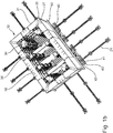
- Figure 1b allows a look into the interior of the formwork core 30.
- Four vertical corner supports 34 can be seen, each of which carries two corner connection panels 31. Two of the total of eight corner connection panels 31 are arranged at right angles to one another at a corner so that they enclose one of the four corners of the formwork core 30.
- the corner supports 34 also each have a corner bracket 35 which closes the gap between the two associated corner connection panels 31 and thus forms a vertical outer edge of the formwork core 30.
- two vertical side supports 36 are arranged along the two longitudinal sides of the formwork core 30. These side supports 36 carry the side formwork panels 32.
- the corner supports 34 and the side supports 36 are each detachably fastened in pairs on a common base frame 40.
- the distance between the corner supports 34 or side supports 36 mounted on a base frame 40 is variable, so that the width of the formwork core 30 can be adjusted.
- the base frames 40 have a number of upwardly open fastening grooves 41 arranged parallel to one another.
- the base frames 40 comprise a plurality of T-beams 42 which are arranged parallel and at a distance from one another and between which the fastening grooves 41 are formed. The ends of the T-beams 42 are screwed onto narrow cross beams 43, which are placed on the base plate 10 (cf. Fig. 1 ) rest.
- the guide rails 24 for the outer supports 23 protrude beyond the outer contour of the formwork core 30, so that the outer formwork 20 ( Fig. 1a ) can be moved far enough to the outside.
- a lifting frame 50 reaches under the lower edges of the formwork core 30. If this lifting frame 50 is moved upwards after the concrete has hardened, the (not shown) hardened concrete part of the outer walls of the formwork core 30; At the same time, the formwork core 30 shrinks in that the corner connection panels 31, the side panels 32 and the corner angle pieces 35 are drawn in in a synchronized manner. As a result, the outer sides of the formwork core detach from the concrete part.
- the corner brackets run forward.
- the kinematics can be driven electrically, hydraulically or purely mechanically.
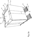
- Fig. 2a and the formwork core 50 shown in the following figures is somewhat smaller, in particular narrower and shorter than the previously described formwork core 30 according to FIG Fig. 1a , 1b .
- Both formwork cores 30 and 50 are constructed in the same way in principle.
- the smaller formwork core 50 is also designed as a shrink core.
- the side formwork elements of the formwork core 50 comprise a total of eight corner connection panels 51, four side formwork panels 52 arranged between them and a central, approximately square ceiling formwork panel 53. In Fig. 2a the side-form elements are raised a little bit upwards.
- the gap between the two corner connection panels 51 of a corner is filled by an elongated corner angle piece 55, which forms the vertical outer edge of the formwork core 50.
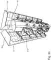
- the load-bearing structure of the formwork core 50 is formed in particular by four vertical corner supports 54, as from the Figures 2b , 2c and 2d is easy to see.
- Two of these corner supports 54 are releasably attached to a common base frame 60 ( Fig. 2a ).
- the corner supports 54 have at their lower end base plates 56 with fastening screws 56a inserted therein ( Fig. 2d ).
- the lower (not visible) ends of the fastening screws 56a engage in fastening grooves 61 of the base frame 60.
- the base frames 60 essentially consist of six T-beams 62, which are arranged parallel to one another and at some distance from one another, the ends of which are screwed onto transverse beams 63.
- the T-beams 62 form the fastening grooves 61 with a T-shaped profile. After loosening the fastening screws 56a, the corner supports 54 can be displaced longitudinally in the fastening grooves 61 in order in this way to increase or decrease the distance between the corner supports 54 and thus to change the length of the formwork core 50.
- the corner supports 54 each have two brackets 57 which are arranged at right angles to one another across corners. These holders 57 are articulated to the corner supports 54 by pivot levers 58. In a similar way, the corner brackets 55 are articulated to the corner supports 54 via lever arms 59 (cf. Figure 2b ). The corner connection panels 51 are mounted on the brackets 57 (cf. Figure 2c ).
- FIG. 3 shows the upper end of a corner support 54.
- the corner support 54 has a hexagonal cross section.
- the pivot levers 58 for the corner connection panels 51 and the lever arm 59 for the corner angle piece 55 protrude outwards.
- the corner bracket 55 has moved inwards a little, so that a gap has arisen between the two adjoining corner connection panels 51 in the area of the corner. When the formwork core 50 is fully extended, this gap is of course closed.
- the adjacent corner connection panels 51 have already moved up a little here.
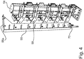
- Fig. 4 shows the cross-sectional profile of the corner angle pieces 55.
- the corner bracket 55 essentially consists of an elongated L-profile. At the upper end there is a ceiling web 55a which is attached at a right angle and points inward.
- the corner connection panels 51 have ceiling webs 51b attached to the inside at right angles ( Figure 2c , Fig. 3 ).
- the corner brackets 55 also have a ceiling web 55a attached at right angles inward at their upper end, as in particular in FIG Figures 2b and 4th is recognizable.
- the side panels 52 have ceiling webs 52b of the same length (cf. Figure 2c and Fig. 3 ).
- the corner angle pieces 55 are resiliently mounted at their lower ends on pressure plates 70 (cf. Fig. 4 ). As a result, the ceiling webs 55a of the corner brackets 55 can slide under the ceiling webs 52b of the adjoining corner connection panels 51 when the formwork core 50 is shrunk (cf. Fig. 3 , Fig. 2a , Figure 2b ).
- FIG. 2d shows the formwork core 50 in a state in which the corner connection panels 51 are still almost completely extended outwards, but the corner angle pieces 55 have already been pulled a little bit inwards or downwards.
- Figure 2b the corner connection panels 51 and the corner angle pieces 55 have moved a little further upwards, so that the way is free to now pull in the corner connection panels 51 further inwards. In doing so, they detach themselves from the walls (not shown) of the concreted bell body on the outside.
Landscapes
- Engineering & Computer Science (AREA)
- Architecture (AREA)
- Mechanical Engineering (AREA)
- Manufacturing & Machinery (AREA)
- Chemical & Material Sciences (AREA)
- Ceramic Engineering (AREA)
- Civil Engineering (AREA)
- Structural Engineering (AREA)
- Forms Removed On Construction Sites Or Auxiliary Members Thereof (AREA)
Description
Die vorliegende Erfindung betrifft einen Schalungskern für ein Schalungssystem zum Betonieren eines Glockenkörpers, insbesondere größeren Bauzellen von Wohngebäuden.The present invention relates to a formwork core for a formwork system for concreting a bell body, in particular larger construction cells of residential buildings.
Ein solches Schalungssystem besteht im Wesentlichen aus einer Außenschalung und dem Schalungskern, der in der Regel quaderförmig ausgebildet ist und in die Außenschalung eingesetzt wird. Die Außenschalung hat einen ortsfesten Schalungsboden sowie vertikale Längswände und Stirnwände, die auf einem Schalungsboden aufstehen. Der Schalungskern sitzt zwischen den Schalwänden der Außenschalung. In den verbleibenden Raum zwischen Außenschalung und Schalungskern wird flüssiger Beton gedrückt. Nach dem Erhärten des Betons werden die Außenschalungselemente entfernt. Um den Schalungskern von den Innenwänden des fertig betonierten Glockenkörpers zu lösen, müssen die Seitenschalungselemente des Schalungskerns nach innen eingezogen werden, um von dem fertigen Betonteil gelöst zu werden.Such a formwork system essentially consists of an outer formwork and the formwork core, which is generally cuboid and is inserted into the outer formwork. The outer formwork has a stationary formwork base as well as vertical longitudinal walls and end walls that stand up on a formwork base. The formwork core sits between the formwork walls of the outer formwork. Liquid concrete is pressed into the remaining space between the outer formwork and the formwork core. After the concrete has hardened, the outer formwork elements are removed. In order to detach the formwork core from the inner walls of the concreted bell body, the side formwork elements of the formwork core must be drawn inwards in order to be detached from the finished concrete part.
Schalungskerne mit nach innen einziehbaren Seitenschalungselementen, sogenannte Schrumpfkerne, sind aus dem Stand der Technik bekannt.Formwork cores with inwardly retractable side formwork elements, so-called shrink cores, are known from the prior art.
Das europäische Patent
Ein weiteres älteres Patent der Anmelderin,
Während die Außenschalung aus vergleichsweise einfachen, im Prinzip ebenen Schalungswänden besteht, ist ein Schalungskern mit nach innen einziehbaren Seitenschalungselementen recht kompliziert und technisch aufwendig gebaut.While the outer formwork consists of comparatively simple, in principle flat formwork walls, a formwork core with inwardly retractable formwork elements is quite complicated and technically complex.
Die Gesamtkosten für ein Schalungssystem zum Betonieren eines Glockenkörpers werden deshalb vor allem von den Kosten für den komplizierten Schalungsinnenkern bestimmt.The total costs for a formwork system for concreting a bell body are therefore primarily determined by the costs for the complicated inner formwork core.
Die zum Betonieren eines quaderförmigen Glockenkörpers benötigten Außenschalungselemente sind im Prinzip als ebene Schalungstafeln ausgebildet. Deshalb können die Außenschalungsteile immer wieder verwendet werden, selbst dann, wenn ein Glockenkörper mit anderen Abmessungen, insbesondere größerer oder kleinerer Breite und/oder Länge hergestellt werden soll. Es genügt, die flachen Schalwände einfach neu zusammenzustellen.The outer formwork elements required for concreting a cuboid bell body are in principle designed as flat formwork panels. Therefore, the outer formwork parts can be used again and again, even if a bell body with different dimensions, in particular larger or smaller width and / or length, is to be produced. It is sufficient to simply reassemble the flat formwork walls.
Ein Schrumpfkern kann dagegen immer nur für eine bestimmte Raumzelle mit vorgegebenen festen Abmessungen in drei Dimensionen verwendet werden. Aufgrund der aufwendigen Konstruktion und der komplizierten Verstellmechanik lässt sich ein solcher Schrumpfkern nur schwer wieder in seine Einzelteile zerlegen, um diese zur Herstellung eines neuen Schalungskerns mit anderen Maßen wiederzuverwenden. Dies hat zur Folge, dass die herkömmlichen Schrumpfkerne üblicherweise nur dann eingesetzt werden, wenn eine größere Anzahl identischer Glockenkörper betoniert werden soll, da dann die relativ hohen Kosten des Schalungskerns auf die Anzahl der produzierten Betonteile umgelegt werden kann.A shrink core, on the other hand, can only ever be used for a specific space cell with predetermined fixed dimensions in three dimensions. Due to the complex construction and the complicated adjustment mechanism, such a shrink core can only be dismantled into its individual parts with difficulty in order to reuse them for the production of a new formwork core with different dimensions. As a result, the conventional shrink cores are usually only used when a larger number of identical bell bodies are to be concreted, since the relatively high costs of the formwork core can then be allocated to the number of concrete parts produced.
Vor diesem Hintergrund ist es Aufgabe der vorliegenden Erfindung, einen Schalungskern mit nach innen einziehbaren Seitenschalungselementen zu schaffen, welcher schnell und einfach so verändert werden kann, dass er zur Herstellung von Glockenkörper unterschiedlicher Abmessungen, insbesondere unterschiedlicher Breite und Länge, verwendbar ist.Against this background, the object of the present invention is to create a formwork core with inwardly retractable side formwork elements, which can be changed quickly and easily so that it can be used for the production of bell bodies of different dimensions, in particular different widths and lengths.
Bei der Lösung dieses Problems wird ausgegangen von einem Schalungskern gemäß dem Oberbegriff des ersten Patentanspruchs, umfassend eine Basis, vertikale Eckstützen und Seitenschalungselemente, die über Schwenkhebel an den Eckstützen derart aufgehängt sind, dass die Seitenschalungselemente nach innen einziehbar sind.The solution to this problem is based on a formwork core according to the preamble of the first claim, comprising a base, vertical corner supports and side formwork elements which are suspended from the corner supports via pivot levers in such a way that the side formwork elements can be retracted inward.
Gelöst wird die Aufgabe durch die Merkmale des kennzeichnenden Teils des ersten Patentanspruchs.The object is achieved by the features of the characterizing part of the first claim.
Bei dem erfindungsgemäßen Schalungskern sind je zwei Eckstützen in variablem Abstand auf einem gemeinsamen Grundrahmen lösbar befestigt. Die Eckstützen tragen jeweils zwei Eckanschlusstafeln, welche rechtwinklig zueinander angeordnet sowie synchron einziehbar und ausfahrbar sind, ohne sich dabei zu berühren. Die Eckanschlusstafeln haben eine ebene Außenwand, die als Schalwand ausgebildet ist. In vollständig ausgefahrenem Zustand verbleibt ein schmaler vertikaler Spalt zwischen den beiden Eckanschlusstafeln im Bereich der Ecke.In the case of the formwork core according to the invention, two corner supports are releasably attached to a common base frame at a variable distance. The corner supports each carry two corner connection panels, which are arranged at right angles to one another and can be retracted and extended synchronously without touching one another. The corner connection panels have a flat outer wall that is designed as a formwork wall. When fully extended, a narrow vertical gap remains between the two corner connection panels in the area of the corner.
Die Eckstützen tragen ferner je ein Eckwinkelstück, welches synchron mit den Eckanschlusstafeln einziehbar und ausfahrbar ist. In vollständig ausgefahrenem Zustand schließt dieses Eckwinkelstück den Spalt zwischen den beiden zugehörigen Eckanschlusstafeln und bildet dadurch eine vertikale Außenkante des Schalungskerns.The corner supports also each have a corner bracket that can be retracted and extended synchronously with the corner connection panels. In the fully extended state, this corner bracket closes the gap between the two associated corner connection panels and thereby forms a vertical outer edge of the formwork core.
Erfindungsgemäß sind die von der Ecke abgelegenen vertikalen Kanten der Eckanschlusstafeln derart ausgebildet, dass sie lösbar miteinander verbindbar sind. Dadurch wird es möglich, dass die in einer Ebene liegenden Eckanschlusstafeln, die z. B. eine Seitenfläche des Schalungskerns bilden, direkt miteinander verbindbar sind. Der dadurch entstandene Schalungskern hat dann eine minimale Länge bzw. Breite. Bei Bedarf können eine oder gegebenenfalls auch mehrere Zwischenelemente zwischen die Eckanschlusstafeln einer Seite lösbar eingesetzt werden. Auf diese Weise kann die Breite bzw. Länge des Schalungskerns auf sehr einfache Weise vergrößert werden, wenn ein größerer Glockenkörper betoniert werden soll. Bei Bedarf lässt sich der erfindungsgemäße Schalungskern auch wieder auf seine ursprünglichen Abmessungen zurückrüsten, indem die gegeneinander weisenden vertikalen Kanten der Eckanschlusstafeln wieder unmittelbar verbunden werden.According to the invention, the vertical edges of the corner connection panels remote from the corner are designed in such a way that they can be detachably connected to one another. This makes it possible that the corner connection panels lying in one plane, the z. B. form a side surface of the formwork core, can be connected directly to one another. The resulting formwork core then has a minimum length or width. If necessary, one or, if necessary, several intermediate elements can be detachably inserted between the corner connection panels on one side. In this way, the width or length of the formwork core can be increased in a very simple manner, if a larger one Bell body is to be concreted. If necessary, the formwork core according to the invention can also be restored to its original dimensions by directly connecting the mutually facing vertical edges of the corner connection panels again.
Der erfindungsgemäß ausgebildete Schalungskern hat also den großen Vorteil, dass er auf einfache Weise an unterschiedliche Abmessungen eines zu betonierenden Glockenkörpers angepasst werden kann, ohne diejenigen Elemente, die konstruktiv aufwendig und damit besonders teuer in der Herstellung sind, zu verändern. Insbesondere die Eckstützen, die an den Eckstützen beweglich gelagerten Eckanschlusstafeln und die Eckwinkelstücke können so immer wieder verwendet werden, selbst wenn die zu betonierenden Hohlkörper sehr unterschiedliche Abmessungen haben. Gleiches gilt für die aufwendige Koppelmechanik für den Antrieb des Schrumpfkerns.The formwork core designed according to the invention thus has the great advantage that it can be easily adapted to different dimensions of a bell body to be concreted without changing those elements that are structurally complex and therefore particularly expensive to manufacture. In particular, the corner supports, the corner connection panels movably mounted on the corner supports and the corner brackets can be used again and again, even if the hollow bodies to be concreted have very different dimensions. The same applies to the complex coupling mechanism for driving the shrink core.
Erfindungsgemäß werden die Ecken des Schalungskerns gebildet von zwei, im Prinzip ebenen Eckanschlusstafeln, welche rechtwinklig zueinander über Eck angeordnet sind, und einem Eckwinkelstück, das den Spalt zwischen den benachbarten Eckanschlusstafeln schließt und die vertikale Außenkante des Schalungskerns bildet. Diese Konstruktion hat den Vorteil, dass die Länge der Eckanschlusstafeln leicht variiert werden kann. Somit ist es möglich, breitere und kürzere bzw. schmalere und längere Schalungskerne sehr einfach zu realisieren, indem einfach kürzere oder längere Eckanschlusstafeln verwendet werden. Die Eckstützen mit ihren aufwendigen Hebelmechanismen und den angekoppelten Eckwinkelstücken können in jedem Fall ohne Veränderung verwendet werden.According to the invention, the corners of the formwork core are formed by two, in principle flat corner connection panels, which are arranged at right angles to each other across corners, and a corner bracket that closes the gap between the adjacent corner connection panels and forms the vertical outer edge of the formwork core. This construction has the advantage that the length of the corner connection panels can be varied easily. It is thus possible to very easily realize wider and shorter or narrower and longer formwork cores by simply using shorter or longer corner connection panels. The corner supports with their complex lever mechanisms and the attached corner brackets can in any case be used without modification.
Um die von der Ecke abgelegenen vertikalen Kanten der Eckanschlusstafeln schnell und einfach, gleichwohl aber fest zu verbinden und später wieder zu lösen, haben die Eckanschlusstafeln an den freien Kanten nach innen weisende Schraubflansche. Mittels dieser Schraubflansche können die Eckanschlusstafeln einer Seite entweder direkt miteinander lösbar verbunden werden oder alternativ ein oder mehrere Verlängerungsteile angesetzt werden. Vorzugsweise sind die Eckwinkelstücke mit den Eckanschlusstafeln derart gekoppelt, dass beim Einziehen, also dem Schrumpfen des Schalungskerns, die Eckwinkelstücke vor den Eckanschlusstafeln nach innen fahren. Dadurch rücken die Eckwinkelstücke aus dem Weg, bevor die zugehörigen Eckanschlusstafeln nach innen eingezogen werden.In order to connect the vertical edges of the corner connection panels that are remote from the corner quickly and easily, but nevertheless firmly, and to detach them again later, the corner connection panels have inwardly facing screw flanges on the free edges. By means of these screw flanges, the corner connection panels on one side can either be directly detachably connected to one another or, alternatively, one or more extension parts can be attached. The corner brackets are preferably coupled to the corner connection panels in such a way that when the formwork core is pulled in, ie when the formwork core is shrunk, the corner brackets move inward in front of the corner connection panels. This moves the corner brackets out of the way before the associated corner connection panels are drawn inwards.
Der erfindungsgemäße Schalungskern wird vorteilhaft ergänzt durch eine zentrale Deckenschaltafel, die horizontal auf den Eckstützen sitzt, wobei die Eckanschlusstafeln und die zugehörigen Eckwinkel derart mit den Eckstützen gekoppelt sind, dass beim Einziehen des Schalungskerns die die Eckanschlusstafeln und zugehörigen Eckwinkelstücke nach innen und gleichzeitig über die ortsfeste Deckenschalungstafel hinaus nach oben fahren. Zwar lässt sich die Länge und die Breite einer solchen Deckenschaltafel nachträglich nicht mehr verändern; da es sich bei diesem Schalungselement aber im Prinzip um eine simple ebene Platte handelt, fällt ein gegebenenfalls erforderlicher Austausch der Deckenschaltafel im Rahmen einer Wiederverwendung der übrigen, wesentlich komplexeren Teile des Schalungskerns zum Betonieren eines Glockenkörpers mit anderen Abmessungen kostenmäßig kaum ins Gewicht.The formwork core according to the invention is advantageously supplemented by a central ceiling panel that sits horizontally on the corner supports, with the corner connection panels and the associated corner brackets being coupled to the corner supports in such a way that when the formwork core is drawn in, the corner connection panels and the associated corner brackets inward and at the same time via the stationary Move the ceiling formwork panel upwards. It is true that the length and width of such a ceiling formwork panel can no longer be changed afterwards; However, since this formwork element is in principle a simple flat plate, any necessary replacement of the ceiling formwork as part of the reuse of the other, much more complex parts of the formwork core for concreting a bell body with different dimensions is hardly significant in terms of cost.
Zweckmäßig haben die Eckanschlusstafeln und die Eckwinkelstücke an ihren Oberkanten Deckenstege, die rechtwinklig nach innen angesetzt sind. In vollständig ausgefahrenem Zustand des Schalungskerns bilden diese Deckenstege zusammen mit der zentralen Deckenschaltafel die Oberseite des Schalungskerns. Mit Beginn der Schrumpfung trennen sich die horizontalen Deckenstege von der Deckenschaltafel und fahren nach oben und anschließend nach innen weg.The corner connection panels and the corner brackets expediently have ceiling webs on their upper edges that are set inwards at right angles. When the formwork core is fully extended, these ceiling webs, together with the central ceiling panel, form the top of the formwork core. When the shrinkage begins, the horizontal ceiling webs separate from the ceiling panel and move upwards and then inwards.
Erfindungsgemäß lässt sich der Abstand zwischen zwei Eckstützen variieren, indem diese Eckstützen gemeinsam auf einem Grundrahmen lösbar befestigt sind. Dadurch lässt sich entweder die Breite oder die Länge des Schalungskerns auf einfache Weise anpassen. Bevorzugt wird eine Ausführung, bei welcher die Grundrahmen mehrere parallele Befestigungsnuten haben, in die Befestigungsmittel eingreifen, welche am Fuß der Eckstützen angeordnet sind. Dadurch lassen sich die beiden Eckstützen, die auf diesem Grundrahmen befestigt sind, stufenlos verschieben, um den Abstand zwischen den Eckstützen zu variieren. Besonders bevorzugt wird eine Ausführungsform, bei der die Grundrahmen eine Anzahl von parallel und mit Abstand voneinander angeordnete T-Träger umfassen. Je zwei benachbarte T-Träger bilden dabei eine Befestigungsnut zur Befestigung der Eckstützen.According to the invention, the distance between two corner supports can be varied in that these corner supports are releasably fastened together on a base frame. This allows either the width or the length of the formwork core to be easily adjusted. An embodiment is preferred in which the base frames have several parallel fastening grooves into which the fastening means, which are arranged at the foot of the corner supports, engage. This allows the two corner supports, which are attached to this base frame, to be moved continuously in order to vary the distance between the corner supports. An embodiment is particularly preferred in which the base frames comprise a number of T-beams arranged parallel and at a distance from one another. Each two adjacent T-beams form a fastening groove for fastening the corner supports.
Optional ist zwischen zwei Eckanschlusstafeln, die eine Seitenfläche des Schalungskerns bilden, jeweils mindestens eine Seitenschaltafel lösbar einsetzbar. Dadurch kann die Länge und/oder Breite des Schalungskerns auf einfache Weise vergrößert werden, falls die Eckanschlusstafeln selbst nicht ausreichend lang sind und nicht durch Eckanschlusstafeln größerer Länge ersetzt werden sollen. Im Prinzip können die Eckanschlusstafeln sehr schmal ausgeführt werden, also in horizontaler Richtung sehr kurz ausgebildet sein; die Länge und/oder die Breite des Schalungskerns wird dann im Wesentlichen von den Abmessungen der Zwischenelemente bestimmt.Optionally, at least one side panel can be detachably inserted between two corner connection panels that form a side surface of the formwork core. This allows the length and / or width of the formwork core to be increased in a simple manner if the corner connection panels themselves are not sufficiently long and should not be replaced by corner connection panels of greater length. In principle, the corner connection panels can be made very narrow, that is to say made very short in the horizontal direction; the length and / or the width of the formwork core is then essentially determined by the dimensions of the intermediate elements.
Zweckmäßig haben nicht nur die Eckanschlusstafeln, sondern auch die optional einsetzbaren Seitenschaltafeln an ihren vertikalen Kanten nach innen weisende Schraubflansche, welche mit den Schraubflanschen der Eckanschlussteile korrespondieren. Dies ermöglicht eine schnelle und lösbare Schraubverbindung zwischen Eckanschlusstafeln und Seitenschaltafeln.Appropriately, not only the corner connection panels, but also the optionally usable side panel panels on their vertical edges have inwardly pointing screw flanges which correspond to the screw flanges of the corner connection parts. This enables a quick and detachable screw connection between corner connection panels and side panels.
Ausführungsbeispiele der Erfindung werden nachstehend anhand der beigefügten Zeichnungen näher beschrieben. Es zeigen:
- Figur 1a
- Ein Schalungssystem mit Schalungskern und Außenschalung, in vereinfachter perspektivischer Darstellung;
- Figur 1b
- den Schalungskern des Schalungssystems von
Fig. 1a , ohne Deckenschaltafel; - Figur 2a
- einen zweiten kleineren Schalungskern, in einer perspektivischen Ansicht schräg von oben;
- Figur 2b
- den Schalungskern von
Fig. 2a , ohne Vorderseite; - Figur 2c
- den Schalungskern von
Fig. 2a , ohne Vorderseite, Rückseite und Deckenschaltafel; - Figur 2d
- den Schalungskern von
Fig. 2a , ohne Seitenschalungselemente und Deckenschaltafel; - Figur 3
- eine obere Ecke des Schalungskerns von
Fig. 2a , von der Innenseite gesehen und in vergrößertem Maßstab; - Figur 4
- eine Eckstütze des Schalungskerns von
Fig. 2a mit Eckwinkelstück; - Figur 5
- die Seitenschalungselemente des Schalungskerns von
Fig. 2a , von der Innenseite aus gesehen und in vergrößertem Maßstab.
- Figure 1a
- A formwork system with formwork core and outer formwork, in a simplified perspective illustration;
- Figure 1b
- the formwork core of the formwork system from
Fig. 1a , without ceiling panel; - Figure 2a
- a second smaller formwork core, in a perspective view obliquely from above;
- Figure 2b
- the formwork core of
Fig. 2a , without front; - Figure 2c
- the formwork core of
Fig. 2a , without front, back and ceiling panel; - Figure 2d
- the formwork core of
Fig. 2a , without side formwork elements and ceiling formwork; - Figure 3
- an upper corner of the formwork core of
Fig. 2a , seen from the inside and on an enlarged scale; - Figure 4
- a corner support of the formwork core from
Fig. 2a with corner bracket; - Figure 5
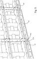
- the side formwork elements of the formwork core of
Fig. 2a , seen from the inside and on an enlarged scale.
Das Schalungssystem gemäß
Die Außenschalung 20 umfasst zwei gegenüberliegende Stirnwände 21, zwei dazu rechtwinklig angeordnete Seitenwände 22 sowie eine Anzahl von vertikalen Außenstützen 23, an denen die Stirnwände 21 und die Seitenwände 22 aufgehängt sind. Die Außenstützen 23 sind in Führungsschienen 24 lösbar befestigt, so dass alle Seitenschalungselemente nach dem Betonieren nach außen weggefahren werden können.The
Der Schalungskern 30 steht zwischen der Außenschalung 20. Das (nicht dargestellte) glockenförmige Betonteil kann nach dem Erhärten vertikal nach oben herausgezogen oder -gedrückt werden, wobei es sich von dem Schalungskern 30 löst. Der Schalungskern 30 hat die Form eines rechteckigen Quaders, dessen Unterseite offen ist. Seine Außenwände werden gebildet von insgesamt acht Eckenanschlusstafeln 31, vier zwischen zwei Eckenanschlusstafeln 31 eingesetzte Seitenschaltafeln 32 und einer zentralen horizontalen Deckenschaltafel 33 (vergleiche
Zwischen den Eckstützen 34 sind entlang der beiden Längsseiten des Schalungskerns 30 jeweils zwei vertikale Seitenstützen 36 angeordnet. Diese Seitenstützen 36 tragen die Seitenschaltafeln 32.Between the corner supports 34, two vertical side supports 36 are arranged along the two longitudinal sides of the
Die Eckstützen 34 und die Seitenstützen 36 sind paarweise auf je einem gemeinsamen Grundrahmen 40 lösbar befestigt. Der Abstand zwischen den auf einem Grundrahmen 40 montierten Eckstützen 34 bzw. Seitenstützen 36 ist variabel, so dass die Breite des Schalungskerns 30 eingestellt werden kann. Die Grundrahmen 40 haben eine Anzahl von parallel nebeneinander angeordneten, nach oben offenen Befestigungsnuten 41. Die Grundrahmen 40 umfassen mehrere, parallel und mit Abstand voneinander angeordnete T-Träger 42, zwischen denen die Befestigungsnuten 41 ausgebildet sind. Die Enden der T-Träger 42 sind auf schmale Querträger 43 geschraubt, welche auf der Bodenplatte 10 (vergleiche
Die Führungsschienen 24 für die Außenstützen 23 (
Der in
Auch der kleinere Schalungskern 50 ist als Schrumpfkern ausgebildet. Die Seitenschalungselemente des Schalungskerns 50 umfassen insgesamt acht Eckanschlusstafeln 51, vier dazwischen angeordnete Seitenschaltafeln 52 sowie eine zentrale, näherungsweise quadratische Deckenschaltafel 53. In
Die tragende Struktur des Schalungskerns 50 wird insbesondere von vier vertikalen Eckstützen 54 gebildet, wie aus den
Wie insbesondere in
Die vergrößerte Darstellung von
Aus
Die Eckanschlusstafeln 51 haben an ihren Oberkanten rechtwinklig nach innen angesetzte Deckenstege 51b (
Die Eckwinkelstücke 55 sind an ihren unteren Enden auf Druckplatten 70 federnd gelagert (vergleiche
The
Horizontal und vertikal angeordnete Zug- und Druckstäbe steifen die Konstruktion aus (
- 1010
- BodenplatteBase plate
- 2020th
- AußenschalungExternal formwork
- 2121st
- Stirnwand (von 20)Front wall (of 20)
- 2222nd
- SeitenwandSide wall
- 2323
- AußenstützeOutside support
- 2424
- FührungsschieneGuide rail
- 3030th
- SchalungskernFormwork core
- 3131
- Eckanschlusstafel (von 30)Corner connection board (of 30)
- 3232
- SeitenschaltafelSide panel
- 3333
- DeckenschaltafelCeiling switchboard
- 3434
- EckstützeCorner support
- 3535
- EckwinkelstückCorner elbow
- 3636
- SeitenstützeSide support
- 3737
- HubrahmenLifting frame
- 4040
- GrundrahmenBase frame
- 4141
- Befestigungsnut (von 40)Mounting groove (from 40)
- 4242
- T-TrägerT-beam
- 4343
- QuerträgerCross member
- 5050
- (kleiner) Schalungskern(small) formwork core
- 5151
- Eckanschlusstafel (von 50)Corner connection panel (of 50)
- 51a51a
- SchraubflanschScrew flange
- 51b51b
- DeckenstegCeiling walkway
- 5252
- SeitenschaltafelSide panel
- 52a52a
- Schraubflansch (von 52)Screw flange (of 52)
- 52b52b
- Deckensteg (von 52)Ceiling bridge (of 52)
- 5353
- DeckenschaltafelCeiling switchboard
- 5454
- EckstützeCorner support
- 5555
- EckwinkelstückCorner elbow
- 55a55a
- Deckensteg (von 55)Ceiling bridge (of 55)
- 5656
- FußplatteFootplate
- 56a56a
- Befestigungsschraube (in 56)Fixing screw (in 56)
- 5757
- Halterungbracket
- 5858
- SchwenkhebelSwivel lever
- 5959
- HebelarmLever arm
- 6060
- GrundrahmenBase frame
- 6161
- BefestigungsnutFastening groove
- 6262
- T-TrägerT-beam
- 6363
- QuerträgerCross member
- 7070
- Druckplatteprinting plate
Claims (9)
- Formwork core for a formwork system for casting a bell-shaped body, comprising a base, vertical corner supports and side formwork elements, which are rotatably mounted at the corner supports in such a manner that the side formwork elements can be retracted inwards,
wherein
the corner supports (34, 54) each carry two corner connection panels (31, 51), which are arranged perpendicular to each other around the corner and are synchronously retractable and extendable without touching, wherein, in the fully extended state, a narrow vertical gap remains between the two corner connection panels in the area of the corner;
the corner supports each carry a corner bracket (35, 55), which are synchronously retractable and extendable and, in the fully extended state, close the gap between the two corresponding corner connection panels (31, 51) to form a vertical outer edge of the formwork core (30, 50);
the vertical edges of the corner connection panels (31, 51) remote from the corner can be releasably attached to one another, characterized in that
two corner supports (34, 54) each are releasably attached to a common base frame (40, 60) in variable distance. - Formwork core according to claim 1, characterized in that, at the vertical edges remote from the corner, the corner connection panels (31, 51) comprise bolt flanges (52a) that point inwards.
- Formwork core according to any one of the preceding claims, characterized in that the corner brackets (35, 55) are coupled to the corner supports (34, 54) in such a manner that during retraction the corner brackets retract to the inside before the corner connection panels do.
- Formwork core according to any one of the preceding claims, characterized in that a horizontal ceiling formwork panel (33, 53) is mounted on the corner supports (34, 54), and the corner connection panels (31, 51) and the corresponding corner brackets (35, 55) are coupled with the corner supports in such a manner that, when the formwork core is retracted, the corner connection panels and the corner brackets move upwards beyond the ceiling formwork panel.
- Formwork core according to claim 4, characterized in that the corner connection panels (31, 51) and the corner brackets (35, 55) at their upper edges comprise ceiling webs (51b) that are oriented inwards at right angles, and, in the fully extended state of the formwork core, these ceiling webs and the central ceiling formwork panel (33, 51) form the plane top side of the formwork core.
- Formwork core according to any one of the preceding claims, characterized in that the base frames (40, 60) comprise a plurality of parallel fastening grooves (41, 61), which are engaged by fastening means arranged at the bottom of the corner supports (34, 54).
- Formwork core according to claim 6, characterized in that the base frames (40, 60) comprise a number of parallel T-beams (42, 62) that are spaced apart from one another.
- Formwork core according to any one of the preceding claims, characterized in that at least one side formwork panel (32, 52) each can be installed between the corner connection panels (31, 51) that form a side surface of the formwork core (30, 50).
- Formwork core according to claim 8, characterized in that the side formwork panels (32, 52) comprise inwards-pointing bolt flanges (52a) at their vertical edges, which flanges (52a) correspond to the bolt flanges (51a) of the corner connection panels (31, 51).
Priority Applications (7)
| Application Number | Priority Date | Filing Date | Title |
|---|---|---|---|
| EP18173984.8A EP3572198B1 (en) | 2018-05-24 | 2018-05-24 | Formwork core for a formwork system for the concreting of a bell body |
| ES18173984T ES2827191T3 (en) | 2018-05-24 | 2018-05-24 | Formwork core for a formwork system for concreting a bell body |
| SG11202011526QA SG11202011526QA (en) | 2018-05-24 | 2019-04-12 | Formwork core for a formwork system for casting a bell-shaped body |
| MX2020012191A MX2020012191A (en) | 2018-05-24 | 2019-04-12 | Formwork core for a formwork system for concreting a bell body. |
| US17/052,659 US20210238870A1 (en) | 2018-05-24 | 2019-04-12 | Formwork core for a formwork system for casting a bell-shaped body |
| PCT/EP2019/059453 WO2019223936A1 (en) | 2018-05-24 | 2019-04-12 | Formwork core for a formwork system for concreting a bell body |
| PH12020551977A PH12020551977A1 (en) | 2018-05-24 | 2020-11-19 | Formwork core for a formwork system for concreting a bell body |
Applications Claiming Priority (1)
| Application Number | Priority Date | Filing Date | Title |
|---|---|---|---|
| EP18173984.8A EP3572198B1 (en) | 2018-05-24 | 2018-05-24 | Formwork core for a formwork system for the concreting of a bell body |
Publications (2)
| Publication Number | Publication Date |
|---|---|
| EP3572198A1 EP3572198A1 (en) | 2019-11-27 |
| EP3572198B1 true EP3572198B1 (en) | 2020-09-23 |
Family
ID=62455336
Family Applications (1)
| Application Number | Title | Priority Date | Filing Date |
|---|---|---|---|
| EP18173984.8A Active EP3572198B1 (en) | 2018-05-24 | 2018-05-24 | Formwork core for a formwork system for the concreting of a bell body |
Country Status (7)
| Country | Link |
|---|---|
| US (1) | US20210238870A1 (en) |
| EP (1) | EP3572198B1 (en) |
| ES (1) | ES2827191T3 (en) |
| MX (1) | MX2020012191A (en) |
| PH (1) | PH12020551977A1 (en) |
| SG (1) | SG11202011526QA (en) |
| WO (1) | WO2019223936A1 (en) |
Families Citing this family (6)
| Publication number | Priority date | Publication date | Assignee | Title |
|---|---|---|---|---|
| CN113931333A (en) * | 2021-11-02 | 2022-01-14 | 山东海瑞林装饰工程有限公司 | External wall insulation board and production method thereof |
| CN114102816B (en) * | 2021-11-19 | 2022-12-02 | 长安大学 | Polygonal prefabricated thin-shell three-dimensional structure modular mold |
| CN115012645B (en) * | 2022-06-29 | 2023-03-24 | 涿州天保建筑体系有限公司 | Wall formwork, building wall and construction method of building wall |
| CN115306140B (en) * | 2022-09-15 | 2024-06-14 | 中建七局第一建筑有限公司 | Construction method of building aluminum template eye-splice type assembly structure |
| WO2024124283A1 (en) * | 2022-12-16 | 2024-06-20 | Patrick Doherty | An inside corner form assembly and method of stripping thereof |
| CN117381952B (en) * | 2023-12-08 | 2024-02-23 | 山西建投建筑产业有限公司 | Superimposed sheet mould and reinforcing apparatus |
Family Cites Families (13)
| Publication number | Priority date | Publication date | Assignee | Title |
|---|---|---|---|---|
| DE2046903C3 (en) | 1970-09-23 | 1979-09-13 | Fa. Werner Zapf, Vorm. Adam Zapf, 8580 Bayreuth | Box-shaped inner formwork for the serial production of room cells |
| DE2504218C3 (en) | 1975-02-01 | 1982-08-26 | Gärtner, Franz, 7505 Ettlingen | Formwork core for producing room-sized structures, such as room cells, made of concrete or the like. |
| DE2651558A1 (en) * | 1976-11-11 | 1978-05-24 | Elcon Ag | METHOD AND DEVICE FOR PRODUCING SPACE ELEMENTS |
| DE2812974A1 (en) * | 1978-03-23 | 1979-10-04 | Schoenwald Ag | Rapid erection concrete formwork - has corner paired angle plates hinged to walls, with movement permitted |
| US4570896A (en) * | 1984-02-06 | 1986-02-18 | Strickland Systems, Inc. | Slide action inside corner form |
| US4650150A (en) * | 1985-04-19 | 1987-03-17 | Opako, S.A. | Mold apparatus for vertical elements of concrete |
| DE4004654C1 (en) | 1990-02-15 | 1991-05-29 | Hochtief Ag Vorm. Gebr. Helfmann, 4300 Essen, De | Formwork core for garage - has overlapping skins for roof and rear wall with staging |
| US5524861A (en) * | 1994-04-22 | 1996-06-11 | Modal Systems, Inc. | Reusable mold for constructing housing units and method of use thereof |
| US5755982A (en) * | 1994-11-07 | 1998-05-26 | Strickland Industries, Inc. | Concrete casting system |
| ES2281212B1 (en) * | 2002-11-18 | 2008-08-16 | Sistemas Industrializados Barcons, S.L. | IMPROVEMENTS IN THE CONSTRUCTION SYSTEMS OF STRUCTURES OF CONCRETE CONCRETE OR OTHER MATERIAL THROUGH MODULAR AND INTEGRAL HANDLING OF HIGH PRECISION. |
| EP1923185B1 (en) | 2006-11-15 | 2014-08-27 | Ratec Maschinenentwicklungs- und Verwaltungs-GmbH | Method and installation for forming a single-piece prefabricated element made of concrete |
| EP2396155A4 (en) * | 2009-02-10 | 2013-10-30 | Precast Modular Solutions Pty Ltd | Modular building construction arrangement |
| DE102009055690A1 (en) * | 2009-11-25 | 2011-05-26 | Peri Gmbh | Ausschalvorrichtung |
-
2018
- 2018-05-24 ES ES18173984T patent/ES2827191T3/en active Active
- 2018-05-24 EP EP18173984.8A patent/EP3572198B1/en active Active
-
2019
- 2019-04-12 WO PCT/EP2019/059453 patent/WO2019223936A1/en active Application Filing
- 2019-04-12 SG SG11202011526QA patent/SG11202011526QA/en unknown
- 2019-04-12 US US17/052,659 patent/US20210238870A1/en active Pending
- 2019-04-12 MX MX2020012191A patent/MX2020012191A/en unknown
-
2020
- 2020-11-19 PH PH12020551977A patent/PH12020551977A1/en unknown
Non-Patent Citations (1)
| Title |
|---|
| None * |
Also Published As
| Publication number | Publication date |
|---|---|
| SG11202011526QA (en) | 2020-12-30 |
| US20210238870A1 (en) | 2021-08-05 |
| MX2020012191A (en) | 2022-02-15 |
| PH12020551977A1 (en) | 2021-09-13 |
| EP3572198A1 (en) | 2019-11-27 |
| ES2827191T3 (en) | 2021-05-20 |
| WO2019223936A1 (en) | 2019-11-28 |
Similar Documents
| Publication | Publication Date | Title |
|---|---|---|
| EP3572198B1 (en) | Formwork core for a formwork system for the concreting of a bell body | |
| DE2229264C2 (en) | Process for the factory production of the storeys of a building and apparatus for carrying out the process | |
| EP2083977B1 (en) | Formwork system for concreting prefabricated parts, comprising a formwork shell and a formwork core | |
| DE102015113077B4 (en) | Formwork form for a building element and method for stripping | |
| EP2910687B1 (en) | Device and method for the fabrication of a tunnel having multiple tunnel sections | |
| DE2534160A1 (en) | FORMWORK FOR CONCRETE | |
| DE1759214B2 (en) | DEVICE FOR SERIES PRODUCTION OF SINGLE-SIDED OPEN ROOM CELLS MADE OF REINFORCED CONCRETE | |
| EP1347120B1 (en) | Shuttering set with mounting and releasing device | |
| CH640774A5 (en) | Shaping table for prefabricated concrete slabs | |
| DE2935726A1 (en) | DEVICE FOR MOLDING CONCRETE WALLS | |
| DE2122874A1 (en) | Method and device for the production of three-dimensional components formed from concrete or the like | |
| DE102012106997A1 (en) | Device for producing a room cell in monolithic construction | |
| DE2400790C2 (en) | Process and device for the production of room cells made of reinforced concrete, e.g. prefabricated garages | |
| DE2417805C2 (en) | Formwork core for the production of reinforced concrete room cells that are open on one side | |
| DE880057C (en) | Steel formwork for the production of smooth walled walls | |
| EP3529020B1 (en) | Apparatus and method for the one-piece production of a room module having three side elements and a floor element and/or a ceiling element. | |
| DE2548298C2 (en) | Method and cavity formwork wall for building a cavity wall | |
| DE2531284A1 (en) | FORMWORK FOR THE PRODUCTION OF IN PARTICULAR FIVE-SIDED CLOSED, PREFERABLY SQUARE-SHAPED AND MONOLITHIC ROOMS MADE OF REINFORCED CONCRETE | |
| EP0480295B1 (en) | Set for the construction of private or holiday homes | |
| DE2128548C3 (en) | Device for the point-by-point support of prefabricated prestressed concrete slabs. < | |
| DE10016978B4 (en) | Device for producing concrete room cells | |
| DE2115553B2 (en) | Formwork for the serial production of room cells made of concrete with different clear widths | |
| DE938987C (en) | Device for the production of structures, in particular masonry made of loose concrete and. like | |
| DE4316568C1 (en) | Method and device for manufacturing rectangular concrete parts preferably provided with recesses | |
| DE2033514A1 (en) | Method and device for the construction of rooms, in particular for residential use |
Legal Events
| Date | Code | Title | Description |
|---|---|---|---|
| PUAI | Public reference made under article 153(3) epc to a published international application that has entered the european phase |
Free format text: ORIGINAL CODE: 0009012 |
|
| STAA | Information on the status of an ep patent application or granted ep patent |
Free format text: STATUS: THE APPLICATION HAS BEEN PUBLISHED |
|
| AK | Designated contracting states |
Kind code of ref document: A1 Designated state(s): AL AT BE BG CH CY CZ DE DK EE ES FI FR GB GR HR HU IE IS IT LI LT LU LV MC MK MT NL NO PL PT RO RS SE SI SK SM TR |
|
| AX | Request for extension of the european patent |
Extension state: BA ME |
|
| STAA | Information on the status of an ep patent application or granted ep patent |
Free format text: STATUS: REQUEST FOR EXAMINATION WAS MADE |
|
| GRAP | Despatch of communication of intention to grant a patent |
Free format text: ORIGINAL CODE: EPIDOSNIGR1 |
|
| STAA | Information on the status of an ep patent application or granted ep patent |
Free format text: STATUS: GRANT OF PATENT IS INTENDED |
|
| 17P | Request for examination filed |
Effective date: 20200116 |
|
| RBV | Designated contracting states (corrected) |
Designated state(s): AL AT BE BG CH CY CZ DE DK EE ES FI FR GB GR HR HU IE IS IT LI LT LU LV MC MK MT NL NO PL PT RO RS SE SI SK SM TR |
|
| INTG | Intention to grant announced |
Effective date: 20200210 |
|
| GRAS | Grant fee paid |
Free format text: ORIGINAL CODE: EPIDOSNIGR3 |
|
| GRAA | (expected) grant |
Free format text: ORIGINAL CODE: 0009210 |
|
| STAA | Information on the status of an ep patent application or granted ep patent |
Free format text: STATUS: THE PATENT HAS BEEN GRANTED |
|
| AK | Designated contracting states |
Kind code of ref document: B1 Designated state(s): AL AT BE BG CH CY CZ DE DK EE ES FI FR GB GR HR HU IE IS IT LI LT LU LV MC MK MT NL NO PL PT RO RS SE SI SK SM TR |
|
| REG | Reference to a national code |
Ref country code: GB Ref legal event code: FG4D Free format text: NOT ENGLISH |
|
| REG | Reference to a national code |
Ref country code: CH Ref legal event code: EP |
|
| REG | Reference to a national code |
Ref country code: IE Ref legal event code: FG4D Free format text: LANGUAGE OF EP DOCUMENT: GERMAN |
|
| REG | Reference to a national code |
Ref country code: DE Ref legal event code: R096 Ref document number: 502018002518 Country of ref document: DE Ref country code: AT Ref legal event code: REF Ref document number: 1315936 Country of ref document: AT Kind code of ref document: T Effective date: 20201015 |
|
| REG | Reference to a national code |
Ref country code: NL Ref legal event code: FP |
|
| REG | Reference to a national code |
Ref country code: FI Ref legal event code: FGE |
|
| REG | Reference to a national code |
Ref country code: CH Ref legal event code: NV Representative=s name: ISLER AND PEDRAZZINI AG, CH |
|
| PG25 | Lapsed in a contracting state [announced via postgrant information from national office to epo] |
Ref country code: GR Free format text: LAPSE BECAUSE OF FAILURE TO SUBMIT A TRANSLATION OF THE DESCRIPTION OR TO PAY THE FEE WITHIN THE PRESCRIBED TIME-LIMIT Effective date: 20201224 Ref country code: NO Free format text: LAPSE BECAUSE OF FAILURE TO SUBMIT A TRANSLATION OF THE DESCRIPTION OR TO PAY THE FEE WITHIN THE PRESCRIBED TIME-LIMIT Effective date: 20201223 Ref country code: BG Free format text: LAPSE BECAUSE OF FAILURE TO SUBMIT A TRANSLATION OF THE DESCRIPTION OR TO PAY THE FEE WITHIN THE PRESCRIBED TIME-LIMIT Effective date: 20201223 Ref country code: SE Free format text: LAPSE BECAUSE OF FAILURE TO SUBMIT A TRANSLATION OF THE DESCRIPTION OR TO PAY THE FEE WITHIN THE PRESCRIBED TIME-LIMIT Effective date: 20200923 Ref country code: HR Free format text: LAPSE BECAUSE OF FAILURE TO SUBMIT A TRANSLATION OF THE DESCRIPTION OR TO PAY THE FEE WITHIN THE PRESCRIBED TIME-LIMIT Effective date: 20200923 |
|
| PG25 | Lapsed in a contracting state [announced via postgrant information from national office to epo] |
Ref country code: LV Free format text: LAPSE BECAUSE OF FAILURE TO SUBMIT A TRANSLATION OF THE DESCRIPTION OR TO PAY THE FEE WITHIN THE PRESCRIBED TIME-LIMIT Effective date: 20200923 Ref country code: RS Free format text: LAPSE BECAUSE OF FAILURE TO SUBMIT A TRANSLATION OF THE DESCRIPTION OR TO PAY THE FEE WITHIN THE PRESCRIBED TIME-LIMIT Effective date: 20200923 |
|
| REG | Reference to a national code |
Ref country code: LT Ref legal event code: MG4D |
|
| PG25 | Lapsed in a contracting state [announced via postgrant information from national office to epo] |
Ref country code: SM Free format text: LAPSE BECAUSE OF FAILURE TO SUBMIT A TRANSLATION OF THE DESCRIPTION OR TO PAY THE FEE WITHIN THE PRESCRIBED TIME-LIMIT Effective date: 20200923 Ref country code: LT Free format text: LAPSE BECAUSE OF FAILURE TO SUBMIT A TRANSLATION OF THE DESCRIPTION OR TO PAY THE FEE WITHIN THE PRESCRIBED TIME-LIMIT Effective date: 20200923 Ref country code: CZ Free format text: LAPSE BECAUSE OF FAILURE TO SUBMIT A TRANSLATION OF THE DESCRIPTION OR TO PAY THE FEE WITHIN THE PRESCRIBED TIME-LIMIT Effective date: 20200923 Ref country code: RO Free format text: LAPSE BECAUSE OF FAILURE TO SUBMIT A TRANSLATION OF THE DESCRIPTION OR TO PAY THE FEE WITHIN THE PRESCRIBED TIME-LIMIT Effective date: 20200923 Ref country code: PT Free format text: LAPSE BECAUSE OF FAILURE TO SUBMIT A TRANSLATION OF THE DESCRIPTION OR TO PAY THE FEE WITHIN THE PRESCRIBED TIME-LIMIT Effective date: 20210125 Ref country code: EE Free format text: LAPSE BECAUSE OF FAILURE TO SUBMIT A TRANSLATION OF THE DESCRIPTION OR TO PAY THE FEE WITHIN THE PRESCRIBED TIME-LIMIT Effective date: 20200923 |
|
| REG | Reference to a national code |
Ref country code: ES Ref legal event code: FG2A Ref document number: 2827191 Country of ref document: ES Kind code of ref document: T3 Effective date: 20210520 |
|
| PG25 | Lapsed in a contracting state [announced via postgrant information from national office to epo] |
Ref country code: AL Free format text: LAPSE BECAUSE OF FAILURE TO SUBMIT A TRANSLATION OF THE DESCRIPTION OR TO PAY THE FEE WITHIN THE PRESCRIBED TIME-LIMIT Effective date: 20200923 Ref country code: IS Free format text: LAPSE BECAUSE OF FAILURE TO SUBMIT A TRANSLATION OF THE DESCRIPTION OR TO PAY THE FEE WITHIN THE PRESCRIBED TIME-LIMIT Effective date: 20210123 Ref country code: PL Free format text: LAPSE BECAUSE OF FAILURE TO SUBMIT A TRANSLATION OF THE DESCRIPTION OR TO PAY THE FEE WITHIN THE PRESCRIBED TIME-LIMIT Effective date: 20200923 |
|
| REG | Reference to a national code |
Ref country code: DE Ref legal event code: R097 Ref document number: 502018002518 Country of ref document: DE |
|
| PG25 | Lapsed in a contracting state [announced via postgrant information from national office to epo] |
Ref country code: SK Free format text: LAPSE BECAUSE OF FAILURE TO SUBMIT A TRANSLATION OF THE DESCRIPTION OR TO PAY THE FEE WITHIN THE PRESCRIBED TIME-LIMIT Effective date: 20200923 |
|
| PLBE | No opposition filed within time limit |
Free format text: ORIGINAL CODE: 0009261 |
|
| STAA | Information on the status of an ep patent application or granted ep patent |
Free format text: STATUS: NO OPPOSITION FILED WITHIN TIME LIMIT |
|
| PG25 | Lapsed in a contracting state [announced via postgrant information from national office to epo] |
Ref country code: DK Free format text: LAPSE BECAUSE OF FAILURE TO SUBMIT A TRANSLATION OF THE DESCRIPTION OR TO PAY THE FEE WITHIN THE PRESCRIBED TIME-LIMIT Effective date: 20200923 |
|
| 26N | No opposition filed |
Effective date: 20210624 |
|
| PG25 | Lapsed in a contracting state [announced via postgrant information from national office to epo] |
Ref country code: MC Free format text: LAPSE BECAUSE OF FAILURE TO SUBMIT A TRANSLATION OF THE DESCRIPTION OR TO PAY THE FEE WITHIN THE PRESCRIBED TIME-LIMIT Effective date: 20200923 Ref country code: LU Free format text: LAPSE BECAUSE OF NON-PAYMENT OF DUE FEES Effective date: 20210524 |
|
| REG | Reference to a national code |
Ref country code: BE Ref legal event code: MM Effective date: 20210531 |
|
| PG25 | Lapsed in a contracting state [announced via postgrant information from national office to epo] |
Ref country code: IE Free format text: LAPSE BECAUSE OF NON-PAYMENT OF DUE FEES Effective date: 20210524 |
|
| PG25 | Lapsed in a contracting state [announced via postgrant information from national office to epo] |
Ref country code: BE Free format text: LAPSE BECAUSE OF NON-PAYMENT OF DUE FEES Effective date: 20210531 |
|
| GBPC | Gb: european patent ceased through non-payment of renewal fee |
Effective date: 20220524 |
|
| PG25 | Lapsed in a contracting state [announced via postgrant information from national office to epo] |
Ref country code: GB Free format text: LAPSE BECAUSE OF NON-PAYMENT OF DUE FEES Effective date: 20220524 |
|
| P01 | Opt-out of the competence of the unified patent court (upc) registered |
Effective date: 20230523 |
|
| PG25 | Lapsed in a contracting state [announced via postgrant information from national office to epo] |
Ref country code: CY Free format text: LAPSE BECAUSE OF FAILURE TO SUBMIT A TRANSLATION OF THE DESCRIPTION OR TO PAY THE FEE WITHIN THE PRESCRIBED TIME-LIMIT Effective date: 20200923 |
|
| PG25 | Lapsed in a contracting state [announced via postgrant information from national office to epo] |
Ref country code: HU Free format text: LAPSE BECAUSE OF FAILURE TO SUBMIT A TRANSLATION OF THE DESCRIPTION OR TO PAY THE FEE WITHIN THE PRESCRIBED TIME-LIMIT; INVALID AB INITIO Effective date: 20180524 |
|
| PG25 | Lapsed in a contracting state [announced via postgrant information from national office to epo] |
Ref country code: SI Free format text: LAPSE BECAUSE OF FAILURE TO SUBMIT A TRANSLATION OF THE DESCRIPTION OR TO PAY THE FEE WITHIN THE PRESCRIBED TIME-LIMIT Effective date: 20200923 |
|
| PG25 | Lapsed in a contracting state [announced via postgrant information from national office to epo] |
Ref country code: MK Free format text: LAPSE BECAUSE OF FAILURE TO SUBMIT A TRANSLATION OF THE DESCRIPTION OR TO PAY THE FEE WITHIN THE PRESCRIBED TIME-LIMIT Effective date: 20200923 |
|
| PGFP | Annual fee paid to national office [announced via postgrant information from national office to epo] |
Ref country code: NL Payment date: 20240522 Year of fee payment: 7 |
|
| PGFP | Annual fee paid to national office [announced via postgrant information from national office to epo] |
Ref country code: DE Payment date: 20240517 Year of fee payment: 7 |
|
| PGFP | Annual fee paid to national office [announced via postgrant information from national office to epo] |
Ref country code: CH Payment date: 20240602 Year of fee payment: 7 |
|
| PGFP | Annual fee paid to national office [announced via postgrant information from national office to epo] |
Ref country code: ES Payment date: 20240614 Year of fee payment: 7 |
|
| PGFP | Annual fee paid to national office [announced via postgrant information from national office to epo] |
Ref country code: AT Payment date: 20240517 Year of fee payment: 7 |
|
| PGFP | Annual fee paid to national office [announced via postgrant information from national office to epo] |
Ref country code: FR Payment date: 20240522 Year of fee payment: 7 Ref country code: FI Payment date: 20240521 Year of fee payment: 7 |
|
| PG25 | Lapsed in a contracting state [announced via postgrant information from national office to epo] |
Ref country code: MT Free format text: LAPSE BECAUSE OF FAILURE TO SUBMIT A TRANSLATION OF THE DESCRIPTION OR TO PAY THE FEE WITHIN THE PRESCRIBED TIME-LIMIT Effective date: 20200923 |
|
| PGFP | Annual fee paid to national office [announced via postgrant information from national office to epo] |
Ref country code: IT Payment date: 20240531 Year of fee payment: 7 |