EP3567183B1 - Leveling spacer device - Google Patents
Leveling spacer device Download PDFInfo
- Publication number
- EP3567183B1 EP3567183B1 EP19170820.5A EP19170820A EP3567183B1 EP 3567183 B1 EP3567183 B1 EP 3567183B1 EP 19170820 A EP19170820 A EP 19170820A EP 3567183 B1 EP3567183 B1 EP 3567183B1
- Authority
- EP
- European Patent Office
- Prior art keywords
- protection ring
- ring nut
- presser
- base
- tiles
- Prior art date
- Legal status (The legal status is an assumption and is not a legal conclusion. Google has not performed a legal analysis and makes no representation as to the accuracy of the status listed.)
- Active
Links
- 125000006850 spacer group Chemical group 0.000 title claims description 25
- 239000000463 material Substances 0.000 claims description 34
- 239000004033 plastic Substances 0.000 claims description 22
- 230000003746 surface roughness Effects 0.000 claims description 7
- 238000000576 coating method Methods 0.000 claims description 6
- 239000011248 coating agent Substances 0.000 claims description 5
- 238000000465 moulding Methods 0.000 claims description 5
- 230000000630 rising effect Effects 0.000 claims description 5
- 239000013536 elastomeric material Substances 0.000 claims description 4
- 238000013037 co-molding Methods 0.000 claims description 3
- 230000008878 coupling Effects 0.000 description 17
- 238000010168 coupling process Methods 0.000 description 17
- 238000005859 coupling reaction Methods 0.000 description 17
- 239000000853 adhesive Substances 0.000 description 16
- 230000001070 adhesive effect Effects 0.000 description 16
- 230000000284 resting effect Effects 0.000 description 11
- 239000000243 solution Substances 0.000 description 7
- 238000003780 insertion Methods 0.000 description 4
- 230000037431 insertion Effects 0.000 description 4
- 230000006835 compression Effects 0.000 description 3
- 238000007906 compression Methods 0.000 description 3
- 230000000694 effects Effects 0.000 description 3
- 230000003068 static effect Effects 0.000 description 3
- 238000006243 chemical reaction Methods 0.000 description 2
- 238000009408 flooring Methods 0.000 description 2
- 238000001746 injection moulding Methods 0.000 description 2
- 230000002093 peripheral effect Effects 0.000 description 2
- 241000933773 Sorella Species 0.000 description 1
- 230000001154 acute effect Effects 0.000 description 1
- 230000001464 adherent effect Effects 0.000 description 1
- 238000005452 bending Methods 0.000 description 1
- 238000010276 construction Methods 0.000 description 1
- 230000003247 decreasing effect Effects 0.000 description 1
- 230000001419 dependent effect Effects 0.000 description 1
- 239000003292 glue Substances 0.000 description 1
- 230000002452 interceptive effect Effects 0.000 description 1
- 230000001788 irregular Effects 0.000 description 1
- 230000000670 limiting effect Effects 0.000 description 1
- 239000002184 metal Substances 0.000 description 1
- 238000012986 modification Methods 0.000 description 1
- 230000004048 modification Effects 0.000 description 1
- 230000010355 oscillation Effects 0.000 description 1
- 229920001296 polysiloxane Polymers 0.000 description 1
- 230000002829 reductive effect Effects 0.000 description 1
- 238000006748 scratching Methods 0.000 description 1
- 230000002393 scratching effect Effects 0.000 description 1
- 238000000926 separation method Methods 0.000 description 1
- 230000002269 spontaneous effect Effects 0.000 description 1
- 239000004575 stone Substances 0.000 description 1
Images


Classifications
-
- E—FIXED CONSTRUCTIONS
- E04—BUILDING
- E04F—FINISHING WORK ON BUILDINGS, e.g. STAIRS, FLOORS
- E04F15/00—Flooring
- E04F15/02—Flooring or floor layers composed of a number of similar elements
- E04F15/02005—Construction of joints, e.g. dividing strips
- E04F15/02022—Construction of joints, e.g. dividing strips with means for aligning the outer surfaces of the flooring elements
-
- E—FIXED CONSTRUCTIONS
- E04—BUILDING
- E04F—FINISHING WORK ON BUILDINGS, e.g. STAIRS, FLOORS
- E04F21/00—Implements for finishing work on buildings
- E04F21/20—Implements for finishing work on buildings for laying flooring
- E04F21/22—Implements for finishing work on buildings for laying flooring of single elements, e.g. flooring cramps ; flexible webs
-
- E—FIXED CONSTRUCTIONS
- E04—BUILDING
- E04F—FINISHING WORK ON BUILDINGS, e.g. STAIRS, FLOORS
- E04F21/00—Implements for finishing work on buildings
- E04F21/0092—Separate provisional spacers used between adjacent floor or wall tiles
-
- E—FIXED CONSTRUCTIONS
- E04—BUILDING
- E04F—FINISHING WORK ON BUILDINGS, e.g. STAIRS, FLOORS
- E04F21/00—Implements for finishing work on buildings
- E04F21/18—Implements for finishing work on buildings for setting wall or ceiling slabs or plates
- E04F21/1838—Implements for finishing work on buildings for setting wall or ceiling slabs or plates for setting a plurality of similar elements
- E04F21/1877—Leveling devices
Definitions
- the present invention relates to a leveling spacer device for laying sheet-like products, such as tiles, slabs of natural stone or the like, for the coating of surfaces, such as surfaces that can be walked on, floors, wall or ceiling coatings and the like.
- the known leveling spacer devices generally comprise a base, which can be positioned below the laying surface of at least two (three or four) adjacent tiles, from which at least one separator element rises, suitable to contact, through its lateral sides, the facing sides of the two (three or four) tiles to be placed next to each other on the laying surface, defining the width of the gap between the tiles.
- the leveling spacer device then, is provided with presser means cooperating with an emerging portion of the separator element which rises above the plane defined by the exposed surface of the tiles.
- the presser means are essentially provided with a planar surface facing the base which is adapted to press the exposed surfaces of all the products supported by the same base towards the base itself so as to level the exposed surfaces.
- leveling spacer devices there are various types, one of these types provides that the presser is substantially a wedge which slides on the exposed surface of the products, a further typology of such leveling spacer devices is that of the so-called screw leveling spacer devices and provides that the presser essentially consists of a knob provided with a nut screw which is adapted to be screwed to a threaded stem (or the like) associated with the emerging portion of the separator element.
- the leveling spacer devices in particular the screw-type spacers, have the drawback that the rubbing exerted by the presser on the exposed surface of the tiles, in the last tightening steps, can ruin the exposed surface of the tiles, scratching them. Furthermore, the rubbing between the tiles and the presser can be relieved in the form of centrifugal force on the tiles themselves, which are therefore unevenly enlarged at the device itself, widening or deforming the gap between the tiles, actually making the spacer function of the device itself ineffective.
- a ring nut that can be fitted to the threaded stem of the device installed (i.e. with the base already positioned below the tiles) and resting on the exposed surface of the tiles, which ring nut is suitable to be interposed between the laying surface of the tiles and the knob, so that in the final steps of tightening of the knob, the knob slides on the ring nut itself and this remains firmly fixed to the exposed surface of the tiles through a prismatic connection made between a suitably shaped through hole of the ring nut and the separator element.
- This ring nut involves a dead time of insertion on the installed spacer leveling devices and an additional charge for the personnel assigned to the laying, which sometimes deliberately neglects the use thereof.
- this ring nut with shaped through hole as shown, for instance, in document WO 2016/189423 A1 with anti-rotation function occludes the sight of the gap at the device with the impossibility for the personnel in charge of the laying to verify whether excess adhesive has emerged at the device due to the exercise of the pressure on the presser and, therefore, to remedy it before the hardening of the adhesive.
- One object of the present invention is to overcome the above drawbacks of the prior art with a simple, rational and cost-effective solution.
- the invention in particular, provides a leveling spacer device for laying sheet-like products for the coating of surfaces which comprises:
- the protection ring is configured so as not to stop its rotation - once its second surface comes into contact with the exposed surface of the tiles - without sliding on the exposed surface of the tiles, allowing - instead - the mutual sliding rotation between the presser and the first surface thereof.
- the protection ring due to the different configuration of the first surface with respect to the second surface prevents the presser from rubbing and ruining the exposed surface of the tiles.
- the first surface and the second surface have different configurations, for instance the first surface may have a different (greater) rigidity than the rigidity of the second surface, preferably the first surface may be rigid and the second surface may be substantially deformable and/or soft, for instance resiliently deformable (preferably in an axial direction).
- rigidity means the resistance to deformation, in particular to deformation due to compression and/or shear stress and/or bending, preferably due to compression.
- the second surface may be made of an elastomeric material, for example rubber.
- the anti-sliding effect of the protection ring may be increased and made even more effective, allowing an efficient safeguard of the exposed surface of the tiles.
- the protection ring nut may be afforded in one piece obtained by molding of plastic materials (polymeric materials), more preferably, the protection ring nut may be afforded in one piece obtained by co-molding of plastic materials (polymeric materials), wherein the first surface may be made of a first plastic material, for instance a polymeric material (for example having a first rigidity), and the second surface may be made of a second plastic material, for instance polymeric and/or elastomeric, different from the first plastic material (for example having a second rigidity different to and/or smaller than the first rigidity).
- first plastic material for instance a polymeric material (for example having a first rigidity)
- the second surface may be made of a second plastic material, for instance polymeric and/or elastomeric, different from the first plastic material (for example having a second rigidity different to and/or smaller than the first rigidity).
- the protection ring nut according to the invention may be obtained in a simple manner without requiring assembly operations either for the manufacturer or for the end user.
- the second surface (which may be made of the same material of the first surface or a different material, as described above) may be configured so as to exhibit a surface roughness greater than a surface roughness of the first surface intended to come into contact with the presser.
- the protection ring nut may comprise a through hole suitable for being inserted with clearance onto the threaded stem and onto the separator element.
- the through hole may have a circular shape with a diameter greater than the maximum width of the separator element.
- the protection ring nut does not obstruct the insertion area between the tiles of the separator element and, therefore, allows the view thereof, thus allowing to verify and remove any rise of adhesive before the hardening of the latter.
- the protection ring nut may be rotatably associated (in mutual sliding) relative to an axis of rotation coinciding with the screwing axis, at one end of the presser facing the base.
- the constraining means may comprise snap-on engaging members configured to axially constrain the protection ring nut and the presser in a removable manner while leaving free mutual rotation thereof relative to the axis of rotation.
- the protection ring nut may be previously anchored to the presser with an obvious advantage for the person in charge of laying the tiles, who can thus save time and ensure that the protection ring nut is always in the correct operating position.
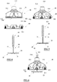
- reference numeral 10 generally designates a leveling spacer device to facilitate the laying of sheet-like products, such as tiles and the like, generally indicated by the letter P, and suitable for coating surfaces, or flooring, walls, ceilings and the like.
- Each tile P adapted to be laid to coat a surface has a wide laying surface P1, for example lower, and an opposite wide exposed surface P2, for example upper, preferably of homologous shape (for example polygonal, preferably quadrangular) with respect to the laying surface P1.
- a wide laying surface P1 for example lower
- an opposite wide exposed surface P2 for example upper, preferably of homologous shape (for example polygonal, preferably quadrangular) with respect to the laying surface P1.
- Each tile P then comprises a plurality of sides P3, generally angled relative to the laying surface P1 and the exposed surface P2, which delimit the tile itself laterally.
- the device 10 comprises a base 20 which is adapted for use to be placed behind the laying surface P1 of the tiles P (shown only schematically in figures 16a-16d ).
- the base 20 in the illustrated example has an enlarged shape, for example polygonal, circular or irregularly shaped, defining a lower surface 21, for example flat or "V", adapted to be arranged distant from the laying surface P1 of the tiles P in and an opposing upper surface 22, for example flat, adapted to be arranged proximal to the laying surface P1 of the tiles P and, for example, in contact therewith.
- the upper surface 22 of the base 20 is in practice intended to receive in support a portion of the laying surface of one or more tiles P (side by side).
- the base 20 is adapted to be immersed in a layer of adhesive arranged on a screed which is intended to be coated by the tiles P, with the lower surface 21 facing the screed itself and the upper surface 22 facing the overlying tiles P.
- the base 20 may be placed resting on a flat fixing surface, such as a joist or the like, and fixed thereto.
- the base 20 is positioned below at least two (or more) adjacent tiles as will appear better below.
- the base 20 in the example shown is defined by a monolithic body, for example made of a plastic material (obtained by injection molding), which has a substantially polygonal shape (in plan).
- the base 20, in the example shown, has an irregular shape (in plan), for example substantially octagonal, elongated along a longitudinal axis.
- the base 20 has a symmetrical shape with respect to a central plane orthogonal to the base itself, for example with respect to a plane orthogonal to the longitudinal axis thereof.
- the base 20 comprises, at the axial ends thereof, a pair of prongs extending parallel to the longitudinal axis of the same base defining therebetween a recess or central slot, for example passing through the thickness of the base.
- such a recess or central slot defines an empty volume that can be filled, in use, by the adhesive, for retaining the laying surface P1 of the tiles P.
- the base 20 may have, for example, a thickness at the central plane (of symmetry orthogonal to the longitudinal axis thereof) which is greater than a thickness thereof at the axial (opposing) ends and, for example decreasing from the central plane towards the axial ends.
- such a thickness gradient of the base facilitates the person in charge of laying the tiles P to insert the base 20 below the laying surface P2 of the tiles P themselves when these are already resting on the layer of adhesive.
- the device 10 also comprises a separator element 30 which rises angled relative to the base 20, for example at the central (symmetry) axis, which is, in use, adapted to slide between facing sides P3 of at least two (or more) tiles P to be placed side by side along a side-by-side direction indicated in the figures with the letter A and contact the same defining the width of the interspace (or gap) between the tiles placed side by side.
- a separator element 30 which rises angled relative to the base 20, for example at the central (symmetry) axis, which is, in use, adapted to slide between facing sides P3 of at least two (or more) tiles P to be placed side by side along a side-by-side direction indicated in the figures with the letter A and contact the same defining the width of the interspace (or gap) between the tiles placed side by side.
- the separator element 30 rises (vertically) from the upper surface 22 of the base angled therewith.
- the separator element 30 is a plate-like parallelepiped body, for example, with a rectangular base (very narrow and long, with a longitudinal axis orthogonal to the longitudinal axis of the base 20 or, however, lying on the central plane of the base itself) which defines a this (and wide) separation wall which divides the upper surface 22 of the base 20 into two opposing portions (equal and symmetrical with respect to the separator element itself in the example).
- the separator element 30 therefore comprises at least two opposing planar and (mutually) parallel faces 31 whose mutual distance defines the thickness of the separator element 30 and, therefore, the width of the gap between the tiles P separated thereby.
- Each face 31 is orthogonal to the upper surface 22 of the base 20.
- each tile P which rests on one of the two portions of the upper surface 22 of the base 20 is adapted to contact one of the faces 31 of the separator element 30. It is not excluded that the separator element 30 may also have an angular spacer arranged angled relative to the faces 31 of the separator element itself.
- the angular spacer may be defined in a single piece with the separator element 30 (for example by interposing a facilitated breakage line, in order to be able to remove the angular spacer if necessary), which in this case may have a substantially cross or "T" section (for example again with a thin wall), so as to divide the upper surface 22 of the base 20, respectively, into four or three opposite portions, on which four or three tiles P can be positioned.
- the separator element 30 for example by interposing a facilitated breakage line, in order to be able to remove the angular spacer if necessary
- T substantially cross or "T" section
- the separator element 30 has a height (intended as the dimension along a direction orthogonal to the base 20) greater than the thickness of the tiles P to be laid, so that the top of the separator element 30, once the tiles are resting (with their own laying surface P1) on the upper surface 22 of the base 20, it protrudes above (abundantly) with respect to the plane to be leveled defined by the exposed surface P2 of the tiles P.
- the separator element 30 has a lower end 32 preferably joined to the base 20 and an opposing free end 33 distal to the base 20.
- the free end 33 may have, for example, upper walls sloping from the center towards the opposite longitudinal ends and, for example, an increased thickness with respect to the rest of the separator element 30.
- the separator element 30 is made in a single body (monolithic) with the base 20, or for example obtained by molding plastic material together with the base itself.
- the separator element 30 has a predetermined breakage line or section 34 which is in use to be arranged below the level of the exposed surface of the tiles P to be spaced and leveled, for example at substantially the same level as the upper surface 22 of the base 20 or, as in the example, slightly higher.
- the predetermined breakage line or section 34 is formed on the separator element 30 in the proximity of the base 20, for example slightly above the level defined by the upper surface 22.
- predetermined breakage line or section 34 may be formed at the junction line between the base 20 and the separator element 30.
- the separator element 30, or the lower end 32 thereof is joined to the base 20 by means of such a predetermined breakage line or section 34, which for example defines a breakage line substantially parallel to the upper surface 22 of the base 20 itself.
- the entire emerging portion of the device 10, comprising the separator element 30, can be easily removed, once the tiles P are laid in place and the adhesive that supports them has hardened, while the portion immersed in the adhesive, i.e. the base 20 (and a small foot portion of the separator element 30), remains trapped (disposable) in the adhesive itself below the laying surface of the leveled tiles P.
- the predetermined breakage line or section 34 extends longitudinally in a direction parallel to the upper surface 22 (and to the central plane) along the entire length of the separator element 30.
- the separator element 30 may have one or more through or blind lightening windows 35, for example in areas of the separator element located below the exposed surface P2 (minimum) of the tiles P to be laid with the device 10.
- the device 10 then comprises a threaded stem 40, for example provided with a male thread 41, which rises perpendicularly to the base 20, preferably from the free end 33 of the separator element 30, axially extending the same.
- a threaded stem 40 for example provided with a male thread 41, which rises perpendicularly to the base 20, preferably from the free end 33 of the separator element 30, axially extending the same.
- the screwing axis is orthogonal to the upper surface 22 of the base 20.
- the male thread 41 extends, for example, substantially over the entire length of the threaded stem 40 and, for example, has a constant pitch.
- the threaded stem 40 in the example has a length substantially twice the height of the separator element 30.
- the threaded stem 40 is made in a single body (monolithic) with the separator element 30 (and the base 20), or for example obtained by molding plastic together with the base itself.
- the device 10 then comprises a presser 50 which is adapted to be screwed onto the threaded stem 40.
- the presser 50 comprises a knob 51 having a globally cup shape or inverted cup shape, or a concave shape (with concavity turned towards the base 20 in use).
- the knob 51 extends, for example, around a central axis C, which is adapted to be arranged coaxial with the threaded stem 40 when the presser 50 is screwed thereon, as will be described more fully below.
- the knob 51 has a substantially frusto-conical or dome shape, i.e. it has an enlarged (lower) end and a tapered opposite top.
- knob 51 may have any other shape, such as cylindrical, butterfly-shaped, handle-shaped, or other suitable shape adapted to be gripped by a hand of a person in charge of laying it for the screwing thereof.
- the enlarged (lower) end of the knob 51 defines an inlet mouth or cavity 510, for example substantially circular (coaxial with the central axis C of the knob itself).
- the inlet cavity 510 has, for example, an inner diameter greater than the outer diameter of the male thread 41 of the threaded stem 40, so that the latter can be inserted axially with abundant radial clearance inside the inlet cavity 510 of the knob 51.
- the inlet cavity 510 has an inner diameter substantially equal to or greater than the width (maximum length) of the separator element 30, so that the latter can be inserted axially with radial clearance inside the inlet cavity 510 of the knob 51 itself, when the presser 50 is screwed onto the threaded stem 40.
- the knob 51 comprises a substantially smooth inner skirt and a shaped outer skirt.
- the outer skirt of the knob 51 for example, comprises reliefs 511 (or ridges), for example in number of 4, to facilitate the grip and the rotation drive for screwing the knob itself.
- Each relief 511 has, for example, a substantially triangular shape, preferably with a side orthogonal to the inlet cavity 510 of the knob 51.
- the knob 51 may have one or more windows 512, for example through or transparent, made at the wall that joins the enlarged (lower) end of the knob 51 with the tapered top thereof.
- each window 512 is made at an interspace (or recess) between two adjacent reliefs 511.
- Each window 512 in the example, goes without interruption from the outer skirt to the inner skirt and forms a descending and connecting ramp and, preferably, has a substantially ogive (rounded and elongated) shape, widened towards the enlarged (lower) end of the knob 51.
- the knob 51 moreover, has a planar end 513 adapted to be turned towards the base 20 (parallel thereto) when the presser 50 is screwed onto the threaded stem 40 and perpendicular to the central axis C of the knob 51.
- the planar end 513 in fact peripherally (and at full extension) delimits the inlet cavity 510 of the knob 51.
- the planar end 513 is for example substantially shaped like a circular crown, preferably defined by the base of a cylindrical shank coaxial to the central axis C and deriving inferiorly from the cap (truncated cone) portion of the knob 51.
- planar end 513 is defined by a pair of concentric circular crowns, each defined for example by the base of a cylindrical shank coaxial to the central axis C, as described above.
- planar end 513 is adapted to be directed in use towards the base 20 (or towards the tiles P resting on the base 20) and defines a perfectly planar annular surface perpendicular to the central axis C of the knob 51.
- the knob 51 comprises, for example at or in the proximity of the planar end 513, an annular step 514 projecting radially towards the outside of the knob itself, for example of the outer skirt thereof and (also) of the reliefs 511.
- the annular step 514 for example, has a substantially circular shape (at least the outer perimeter thereof) and is coaxial to the central axis C (and to the inlet cavity 510).
- the annular step 514 therefore defines a concentric cylindrical (outer) surface with the central axis C of the knob 51.
- the annular step 514 defines a lower annular surface concentric to the central axis C of the knob 51, and for example orthogonal thereto, and an opposite upper annular surface, for example also planar and parallel to the planar end 513 (and placed at an upper level or closer to the top of the knob 51).
- the presser 50 comprises, in particular, a nut screw 515 (female thread) configured to couple (with a helical coupling) with the male thread 41 of the threaded stem 40.
- the female thread 515 has, for example, a screwing axis coinciding with the central axis C of the knob 51.
- the female thread 515 is for example made at (or in proximity of) the tapered top of the knob 51
- the nut screw 515 is defined at an upper shank 516 which rises from the top of the knob 51, for example of a substantially frusto-conical (or cylindrical or prismatic) shape.
- the nut screw 515 passes axially from side to side this upper shank 516 and, for example, at the inner end thereof (i.e. the one leading into the inner skirt of the knob 51) is provided with a groove-shaped taper to facilitate the axial insertion and alignment of the threaded stem 41 with the nut screw 515.
- the nut screw 515 is advantageously defined by a continuous helix, preferably of a plurality of turns.
- the presser 50 in the example shown is defined, as a whole, by a monolithic body, for example made of a plastic material (obtained by injection molding).
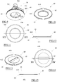
- the device 10 further comprises a protection ring nut 60, which is adapted to be axially interposed - in operation - between the base 20 and the presser 50, or between the presser 50 and the exposed surface P2 of the P tiles resting on the base 20.
- the presser 50 is rotatable (during its screwing rotation around the screwing axis B), in operation, with respect to the protection ring nut 60, which is kept stationary (as will be more apparent later) with respect to the exposed surface P2 of the tiles P.
- the protection ring nut 60 in this case, comprises a sheet-like body 61, for example of thin thickness, preferably of an annular shape (or any shape according to requirements) provided with an upper face (facing the presser 50, when in use) and an opposing lower face (facing the base 20, when in use).
- the protection ring nut 60 or the sheet-like body 61 thereof, comprises - at the upper face thereof - a first surface 610 (upper) intended to face the presser 50, when in use, and - at the lower face thereof - an opposing second surface 611 (lower), which is intended to face the base 20 (or facing the upper surface 22 of the base itself), when in use (i.e. when the protection ring nut 60 is interposed axially between the base 20 and the presser 50 themselves).
- first surface 610 upper
- second surface 611 lower
- the second surface 611 of the protection ring nut 60 is intended to face the surface P2 of the tiles P placed side by side and resting on the upper surface 22 of the base 20 and is configured to contact the exposed surface P2 of the tiles P themselves.
- the first surface 610 and the second surface 611 are, for example, individually planar and substantially parallel to each other; preferably the first surface 610 and the second surface 611, in use, are substantially perpendicular to the screwing axis B of the female thread 515 on the threaded stem 40.
- the first surface 610 is substantially circular in shape.
- the first surface 610 is adapted to contact (sliding, for example along a circular sliding path) with the planar surface 513 of the presser 50, during the screwing rotation of the presser 50 on the threaded stem 40.
- the protection ring nut 60 has a first surface 610 for each planar surface 513 provided in the presser 50.
- the first surface 610 could involve (occupy) the entire area of the upper (annular) face of the protection ring nut 60 or only a portion (annular or partially annular) thereof.
- the protection ring nut 60 may have one or more centering ridges 612 placed at the upper face (surrounding the first surface 610, for example concentric therewith), for example with an annular shape or anyway adapted to define a track annular, engageable by the presser 50, for example to guide the mutual rotation thereof.
- the second surface 611 may be substantially annular, for example of a circular shape (or any shape).
- the second surface 611 may be defined by a plurality of portions of discrete (distinct from each other) and coplanar planar surfaces and/or portions of discrete (distinct from each other) and coplanar precise surfaces that together form a planar surface.
- the second surface 611 is adapted to contact (substantially by adhesion) the exposed surface P2 of the tiles P which rest on (the upper surface 22 of the) base 20 (and remain substantially braked/adhering thereto during the screwing rotation of the presser 50 on the threaded stem 40).
- the second surface 611 in use, is adapted to contact the exposed surface P2 of the tiles P remaining substantially integral therewith (stationary, without friction) during the screwing rotation of the presser 50 on the threaded stem 40.
- the second surface 611 could involve (occupy) the entire area of the lower (annular) face of the protection ring nut 60 or only a portion (annular or partially annular or in any case distributed) thereof.
- the second surface 611 of the protection ring nut 60 is defined by the portion of the lower face of the protection ring nut 60 which is more distal from the upper face of the protection ring nut itself, on which the protection ring nut 60 rests when it is resting on the lower face itself.
- the second surface 611 has a sliding friction coefficient (static or dynamic) greater than the sliding friction coefficient (respectively static or dynamic) of the first surface 610.
- the protection ring nut 60 (or the first surface 610 and the second surface 611 thereof) - and, for example, the presser 50 (or the planar end 513 thereof) - is configured so that the second surface 611 in contact with the exposed surface P2 of the tiles P (whatever they may be) has a sliding friction coefficient greater than the sliding friction coefficient (respectively static or dynamic) of the first surface 610 in contact with the planar end 513 of the presser 50, for instance when they are subjected to the same imposed stress conditions (of mutual sliding and/or mutual sliding during the rotation about the central axis, namely the screwing axis B).
- a sliding friction coefficient i.e. a sliding-resistant force
- the second surface 611 and the first surface 610 with the same conditions of contact with an identical surface (reference), which could be defined by the planar end 513), generate with it (when they are subjected to the same imposed stress conditions) a different sliding-resistant force, such that the sliding-resistant force exerted by the second surface 611 is greater than the sliding-resistant force exerted by the first surface 610.
- the second surface 611 is configured so as to exert a constraining sliding reaction (in opposition to a twisting moment which would cause it to rotate about an axis perpendicular to the second surface itself) on the exposed surface P2 of the tiles P (whatever they are) greater (in modulus) than a constraining sliding reaction (in opposition to a twisting moment which would cause it to rotate about an axis perpendicular to the second surface itself) which the first surface 610 exerts on the planar end 513 of the presser 50.
- the second surface 611 may be adhesive, for example by means of glue (of the attach-detach type) or by means of a suction or similar effect.
- the first surface 610 is made of a material (plastic and/or polymeric) different from the material (plastic and/or polymeric and/or elastomeric) of which the second surface 611 is made.
- the first surface 610 is made of a first substantially rigid (indeformable) material, for example it is made of plastic (or at the limit of metal).
- the second surface 611 is made of a second resilient and/or adhesive and/or (axially) yielding and/or (axially) deformable material, for example it is made of an elastomeric material, such as for example rubber (preferably rigid rubber or plastic rubber) or silicone or another similar material.
- the protection ring nut 60 may be advantageously obtained in a single body by co-molding of plastic materials.
- the protection ring nut 60 may be obtained from the (indissoluble and stable) union of a first supporting body (made of the first aforesaid material), which defines - among other things - also the first surface 610, and one or more second functional bodies (made of the aforesaid second material), which defines the second surface 611.
- the second surface 611 could be defined by the lower surface of one or more second functional bodies (having a defined thickness), of an annular shape or any shape, which have an upper surface (opposite to the lower surface) in direct stable adhesion contact with a superficial interface portion of the first support body of the protection ring nut 60 (at the lower face of the protection ring nut 60 itself).
- a concave seat (with concavity facing downwards) may be defined, for example an annular seat, within which a root portion of the first functional body is received (and fixedly adhered), which emerges axially from the concave seat so as to make the second surface 611 defined thereby emerge (see figure 8 ).
- the second functional bodies are made of a plurality of feet, to examples having a semi-spherical or prismatic shape or any other shape which define, as a whole, a (single) bearing surface such as to constitute the second surface 611.
- the second functional body of the protection ring nut 60 may be defined by an annular body having an outer diameter substantially equal to the outer diameter of the first support body and an inner diameter for example substantially equal to an inner diameter of the first support body itself, in which the first support body is also substantially annular in shape.
- the second surface 611 can be removably associated with the protection ring nut 60.
- the protection ring nut 60 may be obtained from the (separable) union of a first supporting body (made of the first aforesaid material), which defines - among other things - also the first surface 610, and one or more second functional bodies (made of the aforesaid second material), which defines the second surface 611.
- the second surface 611 could be defined by the lower surface of one or more second bodies (having a defined thickness), of an annular shape or whatever, which have an upper surface (opposite to the lower surface) fixed to (for example in direct contact with) a superficial interface portion of the first support body of the protection ring nut 60 (at the lower face of the protection ring nut 60 itself).
- a concave seat (with concavity facing downwards) may be defined, for example an annular seat, within which a root portion of the first functional body is received - such as by interference or snap - which emerges axially from the concave seat so as to make the second surface 611 defined thereby emerge.
- the second functional body may be made by a resilient ring of the "O-ring" type.
- the second functional bodies may be made of a plurality of snap-coupled feet or in any case fixed in a removable manner, for example hemispherical or prismatic in shape or any other shape which define, as a whole, a (single) bearing surface such as to constitute the second surface 611.
- the first surface 610 may be made of a plastic material which is the same as (or even different from) the plastic material of which the second surface 611 is made.
- the difference between the sliding friction coefficient between the first surface 610 and the second surface 611 may be achieved by means of a different configuration of the surface roughness between the first surface 610 and the second surface 611 themselves.
- the protection nut ring 60 - which could be obtained in a single monolithic body by molding a (single) plastic material - may be configured so that the second surface 611 has a surface roughness greater than the surface roughness of the first surface 610 intended to come into contact with the presser 50.
- the protection ring nut 60 then comprises a through hole 62 (through in axial direction), for example central (or coaxial with the first surface 610), which passes through the sheet-like body 61 from side to side and is open at the upper face and the opposite lower face of the protection ring nut 60.
- the through hole 62 has a circular shape with an inner diameter greater than the maximum length of the separator element 30, which can then slide (with its threaded stem 40) axially (with radial clearance) in the through hole 62 of the protection ring nut 60.
- the through hole 62 may have any shape with a minimum diameter that is in any case greater than the maximum length of the separator element 30.
- the through hole 62 has an elongated shape like a slit with a radial longitudinal axis with respect to the central axis of the protection ring nut 60 and preferably passes through the center of the protection ring nut 60.
- this through hole 62 shaped like a slit is centered on the axis of the protection ring nut 60.
- this through hole 62 shaped as a slit is narrow and long, with a length slightly greater than the length of the separator element 30 and with a width slightly greater (for example less than 2 times) the thickness of the separator element 30.
- the through hole 62 shaped like a slit is therefore configured to fit (with clearance) onto the separator element 30 (and to determine a prismatic connection therewith).
- the separator element 30 can be inserted axially inside the through hole 62 shaped as a slit and, once the separator element 30 is engaged inside such a through hole 62 shaped as a slit, the mutual rotation is prevented (except for small oscillations due to the tolerances involved and to the necessary clearance which allows the comfortable insertion of the separator element 30 in the slit 61) between the protection ring nut 60 and the separator element itself.
- the through hole 62 shaped as a slit for example, has substantially straight and parallel lateral ides between which the separator element 30 is substantially accommodated (with reduced lateral clearance).
- Such a through hole 62 shaped as a slit exhibits a dimension such that even the threaded stem 40 can be inserted (with abundant clearance) axially therein.
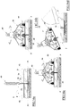
- the protection ring nut 60 is rotatably associated with the presser 50, for example relative to an axis of rotation E coinciding with the screwing axis of the female thread 51 of the presser itself.
- the protection ring nut 60 is adapted to be associated with the planar end 513 of the presser 50, or at the end thereof facing the base 20, so as to interpose itself between the base 20 and such a planar end 513 (and, in use, between the exposed surface of the tiles P and the planar end 503 itself) when the presser 50 is screwed onto the threaded stem 40.
- constraining means adapted to axially constrain the protection ring nut 60 and the presser 50, allowing the (free) reciprocal rotation relative to the axis of rotation E (coinciding with the screwing axis when the protection ring nut 60 is constrained to the presser 50).
- the constraining means are for example a snap coupling configured to axially constrain, in a removable or semi-permanent manner, the protection ring nut 60 and the presser 50 and leaving, as said, the mutual rotation therebetween free relative to the axis of mutual rotation.
- the protection ring nut 60 comprises a plurality of coupling teeth 63 protruding, for example in an axial direction on the opposite side with respect to the second surface 611 and aligned along an imaginary circumference coaxial with respect to the protection ring nut 60 itself and, for example, having a diameter substantially greater than the outer diameter of the annular step 514 of the presser 50.
- Each coupling tooth 63 has a leg 630 rising from the protection ring nut 60 (or from the upper face thereof), one end of which is derived, for example in a single body therewith, from a peripheral portion of the protection ring nut itself and whose opposing free end comprises a hooking head 631 substantially shaped like a pawl facing the axis of rotation E of the protection ring nut 60 and defining a hooking surface 6322, substantially planar, facing the upper face (i.e. the first surface 611) of the protection ring nut itself.
- the coupling surface 632 is away from the upper face (or the first surface 611) of the protection ring nut 60 by a height substantially equal to or slightly greater than the height of the annular step 514.
- the coupling tooth 63 for example the leg 630 thereof, is elastically yielding, preferably in a radial direction, so that it can be snapped onto the presser 50, or to the annular step 514 thereof.
- the coupling tooth 63 for example the leg 630 thereof, has in the direction of its circumferential width thereof an arched conformation (of a circular sector) with concavity turned towards the central axis of the protection ring nut 60.
- the coupling head 631 further defines a surface opposite to the coupling surface 632 which can be inclined with respect to the first surface 610 by an acute grooved angle, such as to impart a radial thrust (towards the outside of the protection ring nut 60) to the hooking tooth 63 following an axial compression thrust on the coupling head 631 of the coupling tooth itself.
- the snap coupling between the presser 50 and the protection ring nut 60 is defined by the coupling between the coupling teeth 63 and the annular step 514.
- the coupling teeth 63 by radially spread, following a mutual axial movement of approach between the presser 50 and the protection ring nut 60, allow the annular step 514 to enter between the coupling teeth themselves, in practice bringing the end planar 513 of the presser 50 in contact (of circumferential sliding) with the first surface of the protection ring nut 60, and possibly the hooking surface 632 of the coupling teeth 63 in contact (of circumferential sliding) with the opposing upper annular surface of the annular step 514.
- the legs 630 of the hooking teeth 63 can define a cylindrical surface (partially) coaxial with the protection ring nut 60 and within which the peripheral edge of the annular step 514 rotates.
- constraining means which mutually constrain the protection ring nut 60 and the presser 50 in an axial direction, leaving the reciprocal rotation free, may be different from those illustrated, for example of the interference type or other suitable connection, either semi-permanent or removable or at the limit permanent, depending on the construction requirements.
- the protection ring nut 60 may be interposed from time to time between the presser 50 and the exposed surface P2 of the tiles P, for example resting with the second surface 611 thereof on the exposed surfaces P2 of the tiles P themselves. Even in this case, however, it is possible to provide that the protection ring nut 60 has centering ridges 612 placed in correspondence with the upper face (surrounding the first surface 610, for example in a concentric manner to it), for example of an annular shape. or in any case adapted to define an annular track, which can be engaged by the pressure element 50, for example to guide its reciprocal rotation, once the first surface 610 is brought into contact with the planar end 513 of the presser 50.
- first device 10 In practice, where the first tile P must be laid, it is sufficient to position a first device 10, the base 20 of which is intended, for example, to be placed under two edges of respective tiles P, an edge and two corners of three respective tiles P or four edges of respective four tiles P, depending on the desired laying pattern.
- a presser 50 is fitted and screwed into a respective threaded stem 40 , so that the presser gradually descending towards the exposed surface P2 of the tiles resting on the base 20 presses on them, locally at the various points (middle or corner), allows the perfect leveling of the exposed surfaces P2 of the tiles themselves affected by the same device 10
- the protection ring nut 60 and the presser 50 it is sufficient to axially insert the free end of the threaded stem 40 of the through hole 62 and, from it, within the inlet cavity 510 of the presser 50 until the male thread 41 enters the female thread 51. Subsequently, in order to quickly bring the second surface 611 of the protection ring nut 60 close to the visible surface of the tiles P it is sufficient to impart a twisting moment (right-handed) on the upper shank 516 (by two fingers) so that the nut screw 51 engages the thread male 41 of the threaded stem 40 and, preferably spontaneously, the presser 50 is screwed quickly onto the threaded stem 40.
- a twisting moment right-handed
- the axial (spontaneous) stroke of the presser 50 is interrupted when the second surface 611 of the protection ring nut 60 reaches the exposed surface P2 of one or more of the tiles P superimposed over it axially.
- the person in charge of laying by rotating the presser 50, for example by gripping the reliefs 511 with his fingers, screws the latter onto the threaded stem 40 so as to exert a gradual pressure, suitably calibrated and controllable, on the exposed surface P2 of all the tiles P on which the second surface 611 of the protection ring nut 60 rests.
- the protection ring nut 60 remains stationary (integral with the tiles P and/or the threaded stem 40 and the separator element 30) although it can slide axially.
- the second surface 611 defines an adherent support surface (anti-sliding) on the exposed surface P2 of the tiles P on which it rests which prevents the protection ring nut 60 from being able to rotate although subjected to a twisting moment due to the sliding contact between the planar end 513 of the presser 50 and the first surface 610 of the protection ring nut 60.
- the difference in the friction coefficient between the first surface 610 and the second surface 611 of the protection ring nut 60 is such as to allow the reciprocal rotation (with respect to the screwing axis B) of the presser 50 and the protection ring nut 60, albeit in mutual sliding contact by means of the first surface 611, but at the same time preventing the reciprocal rotation (with respect to the screwing axis B) between the protection ring nut 60 and the exposed surface P2 of the tiles P resting on the base 20 and in contact with the second surface 611 of the protection ring nut 60.
- the planar end 513 of the pressure element 50 slides during the screwing rotation which allows the clamping of the presser 50 and - therefore - the leveling of the tiles P, on the first surface 610 of the protection ring nut 60, in fact not interfering with the exposed surface P2 of the tiles P themselves.
Applications Claiming Priority (1)
| Application Number | Priority Date | Filing Date | Title |
|---|---|---|---|
| IT102018000005212A IT201800005212A1 (it) | 2018-05-09 | 2018-05-09 | Dispositivo distanziatore livellante |
Publications (2)
| Publication Number | Publication Date |
|---|---|
| EP3567183A1 EP3567183A1 (en) | 2019-11-13 |
| EP3567183B1 true EP3567183B1 (en) | 2021-06-09 |
Family
ID=63080302
Family Applications (1)
| Application Number | Title | Priority Date | Filing Date |
|---|---|---|---|
| EP19170820.5A Active EP3567183B1 (en) | 2018-05-09 | 2019-04-24 | Leveling spacer device |
Country Status (5)
| Country | Link |
|---|---|
| US (1) | US11002025B2 (it) |
| EP (1) | EP3567183B1 (it) |
| CA (1) | CA3040997A1 (it) |
| ES (1) | ES2888654T3 (it) |
| IT (1) | IT201800005212A1 (it) |
Families Citing this family (15)
| Publication number | Priority date | Publication date | Assignee | Title |
|---|---|---|---|---|
| AU2019219811A1 (en) * | 2018-08-24 | 2020-03-12 | Adhesive Construction Technology Australia Pty Ltd | Tile Positioning Device |
| USD956520S1 (en) * | 2019-10-28 | 2022-07-05 | Marshalltown Company | Cross-shaped threaded spacer for a tile leveling system |
| USD962038S1 (en) * | 2019-10-28 | 2022-08-30 | Marshalltown Company | Threaded spacer for tile leveling system |
| USD988828S1 (en) | 2019-10-28 | 2023-06-13 | Marshalltown Company | Leveling cap for tile leveling system |
| USD956519S1 (en) * | 2019-10-28 | 2022-07-05 | Marshalltown Company | T-shaped threaded spacer for a tile leveling system |
| ES1243058U (es) * | 2019-12-24 | 2020-03-09 | Plasdecor Castellon S L | Dispositivo nivelador para baldosas y pavimentos |
| IT202000009568A1 (it) * | 2020-04-30 | 2021-10-30 | Dakota Group S A S Di Zeno Cipriani & C | Livellatore per piastrelle |
| WO2022029341A1 (es) * | 2020-08-03 | 2022-02-10 | Germans Boada, S.A. | Dispositivo nivelador de baldosas |
| USD951743S1 (en) * | 2020-08-04 | 2022-05-17 | Germans Boada, S.A. | Ceramic tile levelling device |
| US11428019B2 (en) * | 2020-11-16 | 2022-08-30 | Raimondi S.P.A. | Levelling spacer device |
| CN112538959A (zh) * | 2020-12-14 | 2021-03-23 | 河南省予卓信息科技有限公司 | 一种建筑工程用瓷砖铺设敲实装置 |
| US11697942B2 (en) * | 2021-03-22 | 2023-07-11 | Walter Pytlewski | Tile lippage control and tile spacing system and method therefore |
| CN113047150B (zh) * | 2021-04-07 | 2023-03-28 | 济南吉伟建筑工程有限公司 | 一种能够对人行道翘起地砖进行维护的维护设备 |
| US20230091132A1 (en) * | 2021-09-21 | 2023-03-23 | Vincenzo Caruso | Systems for leveling tiles |
| IT202100024488A1 (it) * | 2021-09-23 | 2023-03-23 | Dakota Group S A S Di Zeno Cipriani & C | Dispositivo livellatore per piastrelle |
Family Cites Families (78)
| Publication number | Priority date | Publication date | Assignee | Title |
|---|---|---|---|---|
| US3552257A (en) | 1969-04-11 | 1971-01-05 | Atsushi Tanabe | Fastener adapted for wire cage |
| TR18252A (tr) | 1973-05-17 | 1976-11-10 | Couwenbergs P | Tesviye plakasi |
| CH595528A5 (it) | 1974-09-16 | 1978-02-15 | Irle Deuz Gmbh | |
| US4397125A (en) | 1980-06-04 | 1983-08-09 | Gussler Jr Ova L | System for aligning uneven thickness panel sections |
| JP2544545B2 (ja) | 1991-06-17 | 1996-10-16 | 住友ゴム工業株式会社 | ラジアルタイヤ |
| JPH07305494A (ja) | 1994-05-12 | 1995-11-21 | Saimon Glass Kk | 壁面タイル施工用金具 |
| DE29810627U1 (de) | 1998-06-12 | 1998-10-15 | Krehenwinkel Paul | Fliesenkreuzklammer |
| TW439678U (en) | 2000-04-19 | 2001-06-07 | Joy Ind Co Ltd | Easy-dismountable lodge-in hub |
| TW456396U (en) | 2000-12-26 | 2001-09-21 | Chen Guei Fang | Bookshelf screen |
| US7621100B2 (en) | 2005-02-22 | 2009-11-24 | Davinci Italia/Usa Group, Llc | Tile alignment and leveling device and method for using the same |
| US7257926B1 (en) | 2006-08-24 | 2007-08-21 | Kirby Mark E | Tile spacer and leveler |
| GB2459412B (en) | 2007-03-26 | 2011-12-07 | Q E P Co Inc | Device for leveling and aligning tiles and method for leveling and aligning tiles |
| ES1070518Y (es) | 2009-04-17 | 2009-12-21 | Boada Germans Sa | Dispositivo nivelador para la colocacion de piezas de recubrimiento |
| US7861487B2 (en) | 2009-05-18 | 2011-01-04 | Davinci Italia/Usa Group, Llc | Tile alignment and leveling device |
| CN201614727U (zh) | 2009-09-28 | 2010-10-27 | 上海金博石材建设有限公司 | 石材铺设找平装置 |
| DE102009043465A1 (de) | 2009-09-30 | 2011-03-31 | Brinkmann, Silke | Verlegehilfe |
| EP2330261A1 (de) | 2009-12-07 | 2011-06-08 | Meint Lingel | Fliesenjustiervorrichtung |
| US8542667B2 (en) | 2010-04-14 | 2013-09-24 | Hughes Network Systems, Llc | High capacity satellite communications system |
| US8079199B1 (en) | 2010-08-03 | 2011-12-20 | Davinci Italia/Usa Group, Llc | Tile alignment and leveling device |
| US7954300B1 (en) | 2010-11-05 | 2011-06-07 | Davinci Italia/Usa Group, Llc | Tile alignment and leveling device |
| ITMO20110087A1 (it) | 2011-04-22 | 2012-10-23 | S I R I S R L | Dispositivo ausiliario per la messa in opera di manufatti lastriformi per il rivestimento di pavimenti e/o pareti |
| ITMC20110016U1 (it) | 2011-07-19 | 2013-01-20 | Brunoplast Di Eleuteri Bruno | Dispositivo per la corretta posa in opera di piastrelle da pavimentazione. |
| WO2013023236A1 (en) | 2011-08-18 | 2013-02-21 | Sals Invention Pty Ltd | An improved tile spacer and a method of laying tiles using said tile spacer |
| AU2012307075B2 (en) * | 2011-09-05 | 2017-04-20 | Atr Plastics Pty Ltd | Tile levelling device |
| ITPD20110295A1 (it) | 2011-09-20 | 2013-03-21 | Progress Profiles Spa | Distanziatore livellante per la posa di piastrelle, mattonelle e simili con interposizione di fughe |
| US8578674B2 (en) | 2011-10-30 | 2013-11-12 | Frankie Laine Ross | Bracer spacer |
| US8429879B1 (en) | 2011-11-15 | 2013-04-30 | New Standards Manufacturing Co. | Mechanical edge setting system and method for setting tiles and tuning lippage |
| WO2013084282A1 (ja) | 2011-12-05 | 2013-06-13 | 日立化成株式会社 | 樹脂硬化膜パターンの形成方法、感光性樹脂組成物及び感光性エレメント |
| US9228363B2 (en) | 2012-03-23 | 2016-01-05 | Davinci Italia/USA Group, Inc. | Tile alignment and leveling device |
| JP5546051B2 (ja) * | 2012-03-28 | 2014-07-09 | 株式会社川島織物セルコン | タイル施工治具 |
| CA2784633A1 (en) | 2012-08-01 | 2014-02-01 | S.I.R.I. S.R.L. | Auxiliary device for the installation of plate-shaped products for covering floors and/or walls |
| US20140033641A1 (en) | 2012-08-02 | 2014-02-06 | S.I.R.I S.R.L. | Auxiliary device for the installation of plate-shaped products for covering floors and/or walls |
| AU2012211345A1 (en) | 2012-08-03 | 2014-02-20 | S.I.R.I. S.R.L. | Auxiliary device for the installation of plate-shaped products for covering floors and/or walls |
| CA2881270C (en) | 2012-08-08 | 2020-08-18 | Me Innovations Pty Ltd | Tile leveller and spacing system |
| ITVR20130029A1 (it) | 2013-02-04 | 2014-08-05 | Dakota Group S A S | Livellatore per piastrelle |
| JP2014201997A (ja) | 2013-04-08 | 2014-10-27 | Mno株式会社 | タイル敷設施工具及び牽引ユニット |
| US9260872B2 (en) | 2013-04-09 | 2016-02-16 | Clinton D. Bunch | Device for leveling and aligning tile and method for leveling and aligning tiles |
| ES1080054Y (es) | 2013-04-30 | 2013-10-25 | Torrents Res S L | Dispositivo de nivelacion y alineamiento de piezas de recubrimiento de superficies |
| ITRE20130039A1 (it) | 2013-06-04 | 2014-12-05 | Raimondi Spa | Dispositivo distanziatore livellante per la posa in opera di manufatti lastriformi per il rivestimento di superfici |
| CN103362295A (zh) | 2013-08-12 | 2013-10-23 | 上海沃能实业有限公司 | 竖插式瓷砖定位水平安装装置 |
| AU2014100939A4 (en) | 2013-08-21 | 2014-09-18 | Sals Invention Pty Ltd | An improved tile spacer and a method of laying tiles using said tile spacer |
| TWM473422U (zh) | 2013-11-14 | 2014-03-01 | Ching-Tien Teng | 磁磚整平器 |
| PL226911B1 (pl) | 2014-02-14 | 2017-09-29 | Antoni Duraj | Przyrzad dopłaszczyznowania płytek |
| ES2625635T3 (es) | 2014-03-18 | 2017-07-20 | Profilitec S.P.A. Socio Unico | Dispositivo de nivelación para la colocación de baldosas o similares |
| AU2015251522B2 (en) | 2014-04-25 | 2019-10-31 | Edmund BIEC | Leveling wedge system |
| RU146122U1 (ru) | 2014-06-03 | 2014-09-27 | Дмитрий Анатольевич Семаков | Устройство для выравнивания плитки |
| MA39006A (fr) | 2014-06-04 | 2018-04-04 | Progress Profiles Spa | Croisillons de nivellement pour la pose de carreaux de revêtement mural, carreaux de pavage avec interposition d'espaces |
| ES2636316T3 (es) | 2014-07-11 | 2017-10-05 | Fi.R.P. Di Fiorese M. E C. S.N.C. | Un elemento separador para elementos de revestimiento |
| EP2966238B1 (en) | 2014-07-11 | 2018-06-06 | FI.R.P. di Fiorese M. e C. s.n.c. | Positioning system for covering elements |
| BR102014021953A2 (pt) | 2014-09-04 | 2015-04-07 | Donatti Usinagem E Ferramentaria Ltda Me | Dispositivo nivelador de pisos e revestimentos |
| CN204139562U (zh) | 2014-09-19 | 2015-02-04 | 厦门市坤腾精密配件工业有限公司 | 一种瓷砖校平装置 |
| JP6395538B2 (ja) | 2014-09-22 | 2018-09-26 | Mno株式会社 | タイル敷設施工具及び挟持部材 |
| CN204174898U (zh) | 2014-11-05 | 2015-02-25 | 林建民 | 一种建筑用磁砖平整器 |
| NL1041077B1 (nl) | 2014-12-02 | 2016-10-11 | De Multi-Klusser | Tegel nivelleersysteem voor wand en vloertegels. Dit systeem weet zich te onderscheiden van alle reeds bestaande tegel nivelleersystemen die bekent zijn bij de stand van techniek. Zonder behulp van tang, wiggen, spindel, schroefhuis of kuipje ook geen grondplaat, clips of strips nodig die tijdens gebruik bewerkelijk zijn en gedeeltelijk verloren gaan. Mijn systeem is eenvoudig te gebruiken en in volle omvang te hergebruiken. |
| CN204299130U (zh) | 2014-12-15 | 2015-04-29 | 乐清定一塑业有限公司 | 瓷砖找平器 |
| CN204456799U (zh) | 2015-01-05 | 2015-07-08 | 中科盛博建设集团有限公司 | 一种建筑装修工程用新型墙砖铺贴整平装置 |
| AU2015100045B4 (en) | 2015-01-16 | 2015-06-04 | Sanders, Stephen MR | Top-Tile-Level @ innovative true leveling tile system |
| RU2585128C1 (ru) | 2015-01-20 | 2016-05-27 | Дмитрий Анатольевич Семаков | Устройство для выравнивания плитки |
| US9322186B1 (en) | 2015-02-10 | 2016-04-26 | Jason Chang | Leveling spacer system for panel members |
| CN204609253U (zh) | 2015-03-31 | 2015-09-02 | 刘燕涛 | 瓷砖找平器 |
| CN204609254U (zh) | 2015-04-01 | 2015-09-02 | 刘燕涛 | 一种螺旋夹紧式瓷砖找平装置 |
| ES1138645Y (es) | 2015-04-02 | 2015-07-13 | Plásticos De Jijona Complet S L U | Pieza enroscada |
| CA2887533C (en) * | 2015-04-13 | 2023-09-19 | Garry E. Moon | Methods and apparatuses for aligning tiles |
| US9470003B1 (en) | 2015-04-13 | 2016-10-18 | Garry Ernest Moon | Methods and apparatuses for aligning tiles |
| US9279259B1 (en) * | 2015-05-21 | 2016-03-08 | William P. Russo | Tile lippage removal system |
| US9322185B1 (en) | 2015-05-21 | 2016-04-26 | William P. Russo | Tile lippage removal system |
| US20190093372A1 (en) | 2015-05-21 | 2019-03-28 | William P. Russo | Tile Lippage Threaded Post |
| ES2803673T3 (es) * | 2015-05-22 | 2021-01-28 | Raimondi Spa | Espaciador de nivelación para la colocación de productos tipo losa |
| DE202015102847U1 (de) | 2015-06-02 | 2015-07-01 | Primaplus Industrial Co., Ltd. | Nivellierungssystem |
| US20160369518A1 (en) * | 2015-06-17 | 2016-12-22 | Engineered Products And Services, Inc. | Floor Leveling Device |
| TWM516076U (zh) | 2015-07-28 | 2016-01-21 | Ching-Tien Teng | 磁磚整平器 |
| US9689167B2 (en) | 2015-08-13 | 2017-06-27 | Ching-Tien Teng | Tile leveler |
| CN204940818U (zh) | 2015-08-14 | 2016-01-06 | 邓景天 | 磁砖整平器 |
| AR101851A1 (es) | 2015-09-14 | 2017-01-18 | Leonel Cellotto Maximiliano | Dispositivo de nivelación y separación de placas cerámicas |
| ITUB20153890A1 (it) | 2015-09-25 | 2017-03-25 | Profilitec S P A Socio Unico | Un dispositivo per la posa in opera di piastrelle o similari |
| CN205134907U (zh) | 2015-10-27 | 2016-04-06 | 康利达装饰股份有限公司 | 一种新型瓷砖紧固调平器 |
| RU159258U1 (ru) | 2015-10-29 | 2016-02-10 | Общество с ограниченной ответственностью "ЛИТОКол" | Устройство для выравнивания плиток |
| RU159255U1 (ru) | 2015-10-29 | 2016-02-10 | Общество с ограниченной ответственностью "ЛИТОКол" | Устройство для выравнивания плиток |
-
2018
- 2018-05-09 IT IT102018000005212A patent/IT201800005212A1/it unknown
-
2019
- 2019-04-23 CA CA3040997A patent/CA3040997A1/en active Pending
- 2019-04-24 ES ES19170820T patent/ES2888654T3/es active Active
- 2019-04-24 EP EP19170820.5A patent/EP3567183B1/en active Active
- 2019-05-07 US US16/405,342 patent/US11002025B2/en active Active
Also Published As
| Publication number | Publication date |
|---|---|
| EP3567183A1 (en) | 2019-11-13 |
| IT201800005212A1 (it) | 2019-11-09 |
| US20190345724A1 (en) | 2019-11-14 |
| CA3040997A1 (en) | 2019-11-09 |
| ES2888654T3 (es) | 2022-01-05 |
| US11002025B2 (en) | 2021-05-11 |
Similar Documents
| Publication | Publication Date | Title |
|---|---|---|
| EP3567183B1 (en) | Leveling spacer device | |
| US10151118B2 (en) | Tile leveller and spacing system | |
| US20200347589A1 (en) | Concrete Anchor Coupling Assembly and Anchor Rod Holder | |
| EP3298213B1 (en) | Leveling spacer for the laying of slab products | |
| CA2090123C (en) | Studs and sockets for studded footwear | |
| JP7101657B2 (ja) | 特別なインプラントポスト幾何学形状部を有する上部構造体支持体 | |
| CA2909720C (en) | Floor leveling device | |
| EP2252173B1 (en) | Improved athletic shoe cleat with dynamic traction | |
| US20140033641A1 (en) | Auxiliary device for the installation of plate-shaped products for covering floors and/or walls | |
| US10265108B2 (en) | Bone plate | |
| EP2762658B1 (en) | Device for installation of tiles | |
| US20220178152A1 (en) | Supporting device for laying tiles | |
| US11428019B2 (en) | Levelling spacer device | |
| WO2020245711A1 (en) | Levelling spacer device | |
| AU2019200143B2 (en) | Knob for leveling spacer for laying wall tiles, floor tiles and the like | |
| US20190032699A1 (en) | Securing element | |
| CN210032521U (zh) | 一种贴砖器 | |
| US10508458B1 (en) | Tile alignment and leveling device and method for using same | |
| US11486526B2 (en) | Fixing ring, and assembly of a hose and fixing ring | |
| ITUB20150822A1 (it) | Distanziatore livellante per la posa in opera di manufatti lastriformi. | |
| ITUB20150698A1 (it) | Distanziatore livellante per la posa in opera di manufatti lastriformi | |
| ITUB20150751A1 (it) | Distanziatore livellante per la posa in opera di manufatti lastriformi. | |
| CN116209814A (zh) | 用于瓷砖的校平机 | |
| AU2013207596A1 (en) | A tactile surface indicator |
Legal Events
| Date | Code | Title | Description |
|---|---|---|---|
| PUAI | Public reference made under article 153(3) epc to a published international application that has entered the european phase |
Free format text: ORIGINAL CODE: 0009012 |
|
| STAA | Information on the status of an ep patent application or granted ep patent |
Free format text: STATUS: THE APPLICATION HAS BEEN PUBLISHED |
|
| AK | Designated contracting states |
Kind code of ref document: A1 Designated state(s): AL AT BE BG CH CY CZ DE DK EE ES FI FR GB GR HR HU IE IS IT LI LT LU LV MC MK MT NL NO PL PT RO RS SE SI SK SM TR |
|
| AX | Request for extension of the european patent |
Extension state: BA ME |
|
| STAA | Information on the status of an ep patent application or granted ep patent |
Free format text: STATUS: REQUEST FOR EXAMINATION WAS MADE |
|
| 17P | Request for examination filed |
Effective date: 20200507 |
|
| RBV | Designated contracting states (corrected) |
Designated state(s): AL AT BE BG CH CY CZ DE DK EE ES FI FR GB GR HR HU IE IS IT LI LT LU LV MC MK MT NL NO PL PT RO RS SE SI SK SM TR |
|
| GRAP | Despatch of communication of intention to grant a patent |
Free format text: ORIGINAL CODE: EPIDOSNIGR1 |
|
| STAA | Information on the status of an ep patent application or granted ep patent |
Free format text: STATUS: GRANT OF PATENT IS INTENDED |
|
| INTG | Intention to grant announced |
Effective date: 20210114 |
|
| GRAS | Grant fee paid |
Free format text: ORIGINAL CODE: EPIDOSNIGR3 |
|
| GRAA | (expected) grant |
Free format text: ORIGINAL CODE: 0009210 |
|
| STAA | Information on the status of an ep patent application or granted ep patent |
Free format text: STATUS: THE PATENT HAS BEEN GRANTED |
|
| AK | Designated contracting states |
Kind code of ref document: B1 Designated state(s): AL AT BE BG CH CY CZ DE DK EE ES FI FR GB GR HR HU IE IS IT LI LT LU LV MC MK MT NL NO PL PT RO RS SE SI SK SM TR |
|
| REG | Reference to a national code |
Ref country code: GB Ref legal event code: FG4D |
|
| REG | Reference to a national code |
Ref country code: CH Ref legal event code: EP Ref country code: AT Ref legal event code: REF Ref document number: 1400635 Country of ref document: AT Kind code of ref document: T Effective date: 20210615 |
|
| REG | Reference to a national code |
Ref country code: DE Ref legal event code: R096 Ref document number: 602019005180 Country of ref document: DE |
|
| REG | Reference to a national code |
Ref country code: IE Ref legal event code: FG4D |
|
| REG | Reference to a national code |
Ref country code: SE Ref legal event code: TRGR |
|
| REG | Reference to a national code |
Ref country code: LT Ref legal event code: MG9D |
|
| REG | Reference to a national code |
Ref country code: NO Ref legal event code: T2 Effective date: 20210609 |
|
| PG25 | Lapsed in a contracting state [announced via postgrant information from national office to epo] |
Ref country code: BG Free format text: LAPSE BECAUSE OF FAILURE TO SUBMIT A TRANSLATION OF THE DESCRIPTION OR TO PAY THE FEE WITHIN THE PRESCRIBED TIME-LIMIT Effective date: 20210909 Ref country code: HR Free format text: LAPSE BECAUSE OF FAILURE TO SUBMIT A TRANSLATION OF THE DESCRIPTION OR TO PAY THE FEE WITHIN THE PRESCRIBED TIME-LIMIT Effective date: 20210609 Ref country code: LT Free format text: LAPSE BECAUSE OF FAILURE TO SUBMIT A TRANSLATION OF THE DESCRIPTION OR TO PAY THE FEE WITHIN THE PRESCRIBED TIME-LIMIT Effective date: 20210609 Ref country code: FI Free format text: LAPSE BECAUSE OF FAILURE TO SUBMIT A TRANSLATION OF THE DESCRIPTION OR TO PAY THE FEE WITHIN THE PRESCRIBED TIME-LIMIT Effective date: 20210609 |
|
| REG | Reference to a national code |
Ref country code: AT Ref legal event code: MK05 Ref document number: 1400635 Country of ref document: AT Kind code of ref document: T Effective date: 20210609 |
|
| REG | Reference to a national code |
Ref country code: NL Ref legal event code: MP Effective date: 20210609 |
|
| PG25 | Lapsed in a contracting state [announced via postgrant information from national office to epo] |
Ref country code: GR Free format text: LAPSE BECAUSE OF FAILURE TO SUBMIT A TRANSLATION OF THE DESCRIPTION OR TO PAY THE FEE WITHIN THE PRESCRIBED TIME-LIMIT Effective date: 20210910 Ref country code: RS Free format text: LAPSE BECAUSE OF FAILURE TO SUBMIT A TRANSLATION OF THE DESCRIPTION OR TO PAY THE FEE WITHIN THE PRESCRIBED TIME-LIMIT Effective date: 20210609 Ref country code: LV Free format text: LAPSE BECAUSE OF FAILURE TO SUBMIT A TRANSLATION OF THE DESCRIPTION OR TO PAY THE FEE WITHIN THE PRESCRIBED TIME-LIMIT Effective date: 20210609 |
|
| REG | Reference to a national code |
Ref country code: ES Ref legal event code: FG2A Ref document number: 2888654 Country of ref document: ES Kind code of ref document: T3 Effective date: 20220105 |
|
| PG25 | Lapsed in a contracting state [announced via postgrant information from national office to epo] |
Ref country code: SK Free format text: LAPSE BECAUSE OF FAILURE TO SUBMIT A TRANSLATION OF THE DESCRIPTION OR TO PAY THE FEE WITHIN THE PRESCRIBED TIME-LIMIT Effective date: 20210609 Ref country code: EE Free format text: LAPSE BECAUSE OF FAILURE TO SUBMIT A TRANSLATION OF THE DESCRIPTION OR TO PAY THE FEE WITHIN THE PRESCRIBED TIME-LIMIT Effective date: 20210609 Ref country code: SM Free format text: LAPSE BECAUSE OF FAILURE TO SUBMIT A TRANSLATION OF THE DESCRIPTION OR TO PAY THE FEE WITHIN THE PRESCRIBED TIME-LIMIT Effective date: 20210609 Ref country code: NL Free format text: LAPSE BECAUSE OF FAILURE TO SUBMIT A TRANSLATION OF THE DESCRIPTION OR TO PAY THE FEE WITHIN THE PRESCRIBED TIME-LIMIT Effective date: 20210609 Ref country code: PT Free format text: LAPSE BECAUSE OF FAILURE TO SUBMIT A TRANSLATION OF THE DESCRIPTION OR TO PAY THE FEE WITHIN THE PRESCRIBED TIME-LIMIT Effective date: 20211011 Ref country code: RO Free format text: LAPSE BECAUSE OF FAILURE TO SUBMIT A TRANSLATION OF THE DESCRIPTION OR TO PAY THE FEE WITHIN THE PRESCRIBED TIME-LIMIT Effective date: 20210609 Ref country code: CZ Free format text: LAPSE BECAUSE OF FAILURE TO SUBMIT A TRANSLATION OF THE DESCRIPTION OR TO PAY THE FEE WITHIN THE PRESCRIBED TIME-LIMIT Effective date: 20210609 Ref country code: AT Free format text: LAPSE BECAUSE OF FAILURE TO SUBMIT A TRANSLATION OF THE DESCRIPTION OR TO PAY THE FEE WITHIN THE PRESCRIBED TIME-LIMIT Effective date: 20210609 |
|
| PG25 | Lapsed in a contracting state [announced via postgrant information from national office to epo] |
Ref country code: PL Free format text: LAPSE BECAUSE OF FAILURE TO SUBMIT A TRANSLATION OF THE DESCRIPTION OR TO PAY THE FEE WITHIN THE PRESCRIBED TIME-LIMIT Effective date: 20210609 |
|
| REG | Reference to a national code |
Ref country code: DE Ref legal event code: R097 Ref document number: 602019005180 Country of ref document: DE |
|
| PLBE | No opposition filed within time limit |
Free format text: ORIGINAL CODE: 0009261 |
|
| STAA | Information on the status of an ep patent application or granted ep patent |
Free format text: STATUS: NO OPPOSITION FILED WITHIN TIME LIMIT |
|
| PG25 | Lapsed in a contracting state [announced via postgrant information from national office to epo] |
Ref country code: DK Free format text: LAPSE BECAUSE OF FAILURE TO SUBMIT A TRANSLATION OF THE DESCRIPTION OR TO PAY THE FEE WITHIN THE PRESCRIBED TIME-LIMIT Effective date: 20210609 |
|
| 26N | No opposition filed |
Effective date: 20220310 |
|
| PG25 | Lapsed in a contracting state [announced via postgrant information from national office to epo] |
Ref country code: AL Free format text: LAPSE BECAUSE OF FAILURE TO SUBMIT A TRANSLATION OF THE DESCRIPTION OR TO PAY THE FEE WITHIN THE PRESCRIBED TIME-LIMIT Effective date: 20210609 |
|
| PG25 | Lapsed in a contracting state [announced via postgrant information from national office to epo] |
Ref country code: MC Free format text: LAPSE BECAUSE OF FAILURE TO SUBMIT A TRANSLATION OF THE DESCRIPTION OR TO PAY THE FEE WITHIN THE PRESCRIBED TIME-LIMIT Effective date: 20210609 Ref country code: LU Free format text: LAPSE BECAUSE OF NON-PAYMENT OF DUE FEES Effective date: 20220424 |
|
| PG25 | Lapsed in a contracting state [announced via postgrant information from national office to epo] |
Ref country code: IE Free format text: LAPSE BECAUSE OF NON-PAYMENT OF DUE FEES Effective date: 20220424 |
|
| PGFP | Annual fee paid to national office [announced via postgrant information from national office to epo] |
Ref country code: IT Payment date: 20230228 Year of fee payment: 5 |
|
| P01 | Opt-out of the competence of the unified patent court (upc) registered |
Effective date: 20230504 |
|
| PGFP | Annual fee paid to national office [announced via postgrant information from national office to epo] |
Ref country code: NO Payment date: 20230427 Year of fee payment: 5 Ref country code: FR Payment date: 20230425 Year of fee payment: 5 Ref country code: ES Payment date: 20230503 Year of fee payment: 5 Ref country code: DE Payment date: 20230427 Year of fee payment: 5 Ref country code: CH Payment date: 20230502 Year of fee payment: 5 |
|
| PGFP | Annual fee paid to national office [announced via postgrant information from national office to epo] |
Ref country code: SE Payment date: 20230427 Year of fee payment: 5 |
|
| PGFP | Annual fee paid to national office [announced via postgrant information from national office to epo] |
Ref country code: BE Payment date: 20230427 Year of fee payment: 5 |
|
| PGFP | Annual fee paid to national office [announced via postgrant information from national office to epo] |
Ref country code: GB Payment date: 20230427 Year of fee payment: 5 |
|
| PG25 | Lapsed in a contracting state [announced via postgrant information from national office to epo] |
Ref country code: HU Free format text: LAPSE BECAUSE OF FAILURE TO SUBMIT A TRANSLATION OF THE DESCRIPTION OR TO PAY THE FEE WITHIN THE PRESCRIBED TIME-LIMIT; INVALID AB INITIO Effective date: 20190424 |