EP3543555A1 - Ausgleichskupplung und druckbalken mit einer solchen ausgleichskupplung - Google Patents
Ausgleichskupplung und druckbalken mit einer solchen ausgleichskupplung Download PDFInfo
- Publication number
- EP3543555A1 EP3543555A1 EP18163049.2A EP18163049A EP3543555A1 EP 3543555 A1 EP3543555 A1 EP 3543555A1 EP 18163049 A EP18163049 A EP 18163049A EP 3543555 A1 EP3543555 A1 EP 3543555A1
- Authority
- EP
- European Patent Office
- Prior art keywords
- coupling
- coupling half
- compensating
- screw
- toothing
- Prior art date
- Legal status (The legal status is an assumption and is not a legal conclusion. Google has not performed a legal analysis and makes no representation as to the accuracy of the status listed.)
- Pending
Links
- 230000008878 coupling Effects 0.000 title claims abstract description 91
- 238000010168 coupling process Methods 0.000 title claims abstract description 91
- 238000005859 coupling reaction Methods 0.000 title claims abstract description 91
- 210000000078 claw Anatomy 0.000 claims abstract description 34
- 230000005489 elastic deformation Effects 0.000 claims abstract description 6
- 238000011161 development Methods 0.000 description 4
- 230000018109 developmental process Effects 0.000 description 4
- 230000004048 modification Effects 0.000 description 4
- 238000012986 modification Methods 0.000 description 4
- 238000007639 printing Methods 0.000 description 4
- 238000006073 displacement reaction Methods 0.000 description 3
- 230000005540 biological transmission Effects 0.000 description 2
- 241000309551 Arthraxon hispidus Species 0.000 description 1
- 210000003746 feather Anatomy 0.000 description 1
- 238000007641 inkjet printing Methods 0.000 description 1
Images



Classifications
-
- F—MECHANICAL ENGINEERING; LIGHTING; HEATING; WEAPONS; BLASTING
- F16—ENGINEERING ELEMENTS AND UNITS; GENERAL MEASURES FOR PRODUCING AND MAINTAINING EFFECTIVE FUNCTIONING OF MACHINES OR INSTALLATIONS; THERMAL INSULATION IN GENERAL
- F16D—COUPLINGS FOR TRANSMITTING ROTATION; CLUTCHES; BRAKES
- F16D3/00—Yielding couplings, i.e. with means permitting movement between the connected parts during the drive
- F16D3/02—Yielding couplings, i.e. with means permitting movement between the connected parts during the drive adapted to specific functions
- F16D3/06—Yielding couplings, i.e. with means permitting movement between the connected parts during the drive adapted to specific functions specially adapted to allow axial displacement
-
- F—MECHANICAL ENGINEERING; LIGHTING; HEATING; WEAPONS; BLASTING
- F16—ENGINEERING ELEMENTS AND UNITS; GENERAL MEASURES FOR PRODUCING AND MAINTAINING EFFECTIVE FUNCTIONING OF MACHINES OR INSTALLATIONS; THERMAL INSULATION IN GENERAL
- F16D—COUPLINGS FOR TRANSMITTING ROTATION; CLUTCHES; BRAKES
- F16D13/00—Friction clutches
- F16D13/58—Details
- F16D13/75—Features relating to adjustment, e.g. slack adjusters
- F16D13/757—Features relating to adjustment, e.g. slack adjusters the adjusting device being located on or inside the clutch cover, e.g. acting on the diaphragm or on the pressure plate
-
- B—PERFORMING OPERATIONS; TRANSPORTING
- B41—PRINTING; LINING MACHINES; TYPEWRITERS; STAMPS
- B41J—TYPEWRITERS; SELECTIVE PRINTING MECHANISMS, i.e. MECHANISMS PRINTING OTHERWISE THAN FROM A FORME; CORRECTION OF TYPOGRAPHICAL ERRORS
- B41J2/00—Typewriters or selective printing mechanisms characterised by the printing or marking process for which they are designed
- B41J2/005—Typewriters or selective printing mechanisms characterised by the printing or marking process for which they are designed characterised by bringing liquid or particles selectively into contact with a printing material
- B41J2/01—Ink jet
- B41J2/135—Nozzles
- B41J2/145—Arrangement thereof
- B41J2/155—Arrangement thereof for line printing
-
- F—MECHANICAL ENGINEERING; LIGHTING; HEATING; WEAPONS; BLASTING
- F16—ENGINEERING ELEMENTS AND UNITS; GENERAL MEASURES FOR PRODUCING AND MAINTAINING EFFECTIVE FUNCTIONING OF MACHINES OR INSTALLATIONS; THERMAL INSULATION IN GENERAL
- F16D—COUPLINGS FOR TRANSMITTING ROTATION; CLUTCHES; BRAKES
- F16D3/00—Yielding couplings, i.e. with means permitting movement between the connected parts during the drive
- F16D3/16—Universal joints in which flexibility is produced by means of pivots or sliding or rolling connecting parts
-
- F—MECHANICAL ENGINEERING; LIGHTING; HEATING; WEAPONS; BLASTING
- F16—ENGINEERING ELEMENTS AND UNITS; GENERAL MEASURES FOR PRODUCING AND MAINTAINING EFFECTIVE FUNCTIONING OF MACHINES OR INSTALLATIONS; THERMAL INSULATION IN GENERAL
- F16D—COUPLINGS FOR TRANSMITTING ROTATION; CLUTCHES; BRAKES
- F16D3/00—Yielding couplings, i.e. with means permitting movement between the connected parts during the drive
- F16D3/16—Universal joints in which flexibility is produced by means of pivots or sliding or rolling connecting parts
- F16D3/18—Universal joints in which flexibility is produced by means of pivots or sliding or rolling connecting parts the coupling parts (1) having slidably-interengaging teeth
-
- F—MECHANICAL ENGINEERING; LIGHTING; HEATING; WEAPONS; BLASTING
- F16—ENGINEERING ELEMENTS AND UNITS; GENERAL MEASURES FOR PRODUCING AND MAINTAINING EFFECTIVE FUNCTIONING OF MACHINES OR INSTALLATIONS; THERMAL INSULATION IN GENERAL
- F16D—COUPLINGS FOR TRANSMITTING ROTATION; CLUTCHES; BRAKES
- F16D3/00—Yielding couplings, i.e. with means permitting movement between the connected parts during the drive
- F16D3/16—Universal joints in which flexibility is produced by means of pivots or sliding or rolling connecting parts
- F16D3/18—Universal joints in which flexibility is produced by means of pivots or sliding or rolling connecting parts the coupling parts (1) having slidably-interengaging teeth
- F16D3/185—Universal joints in which flexibility is produced by means of pivots or sliding or rolling connecting parts the coupling parts (1) having slidably-interengaging teeth radial teeth connecting concentric inner and outer coupling parts
-
- F—MECHANICAL ENGINEERING; LIGHTING; HEATING; WEAPONS; BLASTING
- F16—ENGINEERING ELEMENTS AND UNITS; GENERAL MEASURES FOR PRODUCING AND MAINTAINING EFFECTIVE FUNCTIONING OF MACHINES OR INSTALLATIONS; THERMAL INSULATION IN GENERAL
- F16D—COUPLINGS FOR TRANSMITTING ROTATION; CLUTCHES; BRAKES
- F16D7/00—Slip couplings, e.g. slipping on overload, for absorbing shock
- F16D7/04—Slip couplings, e.g. slipping on overload, for absorbing shock of the ratchet type
- F16D7/048—Slip couplings, e.g. slipping on overload, for absorbing shock of the ratchet type with parts moving radially between engagement and disengagement
Definitions
- the present invention relates to a compensating coupling, comprising a first and second coupling half, which are nestable with elastic deformation.
- DE 38 43 825 C1 is a universally movable joint for linkage and propeller shafts described, which consists of two identically formed parts of an elastically deformable plastic, wherein the identically shaped coupling members are nestable with an angular displacement of 90 ° under resilient elastic deformation.
- This joint can also be used as a quick coupling in rods or the like, in particular if such rods require an all-round movable joint to compensate for deflection movements.
- the joint can be used, among other things, in printing presses.
- the adjustment device includes components that must be coupled in many different angular positions relative to each other. These components may be e.g. to act a screw and a shaft to rotate the screw.
- the object of the invention is to provide a compensating coupling, the coupling halves are coupled in more angular positions relative to each other. It is also an object to provide a pressure bar with such a compensation clutch.
- the object is achieved by a compensating coupling with the features of claim 1 and by a pressure bar with the features of claim 8.
- the compensating coupling according to the invention comprises a first coupling half and a second coupling half, which are nestable with elastic deformation, and is characterized in that the first coupling half spring claws and the second coupling half has a toothing, wherein the spring claws have a different pitch than the toothing.
- An additional advantage of the invention is that the clearance in the compensating coupling is minimized.
- the first coupling half can be designed as a wheel and the spring claws can spring in radially.
- the second coupling half can be designed as a star.
- the toothing may have a certain length for axial compensation. It can be provided that the spring claws transmit the torque and cause a compensation of misalignment or deviations between axes of rotation of the coupling halves with respect to axis angle and / or radial misalignment.
- the number of teeth of the toothing may be greater than the number of spring claws.
- the pressure bar for inkjet according to the invention comprises printheads in a row, adjusting devices for adjusting the printheads to each other, wherein the adjusting devices each have at least one screw and at least one shaft for rotating the screw, and is characterized in that the screw and the shaft on the inventive or one of their developments corresponding compensating coupling are interconnected.
- the compensating coupling of the pressure bar according to the invention thus comprises the first coupling half and the second coupling half, which are nestable with elastic deformation, wherein the first coupling half has the spring claws and the second coupling half the Has toothing, and wherein the spring claws have a different pitch than the toothing.
- the second coupling half can be arranged on the screw and the first coupling half can be arranged on the shaft.
- the shaft may be a motor shaft of an engine.
- FIGS. 1 to 7 are mutually corresponding components and elements designated by the same reference numerals.
- FIG. 1 a digital printing machine is shown in which sheets are transported by cylinder from a feeder over several stations to a boom.
- a Station includes structurally identical pressure bars 13 for multi-color page-wide inkjet printing. Each print bar 13 prints a different color.
- Each pressure bar 13 carries a series of print heads 9 - see. FIG. 2 - which extends across the width of the arch.
- the printheads 9 are equipped with nozzles (not shown) from which the ink is ejected.
- Each printhead 9 is associated with an adjusting device 10 with a stop 15 and a spring 16.
- the adjusting devices 10 serve to adjust the print heads 9 relative to one another, which takes place linearly in the given example along the pressure bar 13. But it would also be another adjustment direction, eg in the sheet transport direction, or another Stelliolosform, eg a pivoting movement, possible.
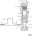
- FIG. 2 one of the printheads 9 and one of the adjusting devices 10 is shown.
- the stop 15 is coupled via a compensating coupling 3 with an electric motor M, which is fastened to a frame 17.
- the motor M is preferably a stepping motor.
- the print head 9 is supported by a holder 18 which bears against the stop 15. But it would also be possible that directly the print head 9 itself rests against the stop 15.
- the stop 15 is formed as a cone and forms a portion of a screw 11.
- the screw 11 may also be referred to as a control shaft or cone shaft.
- the screw 11 has further sections, namely fits 19 as plain bearings and an external thread 20.
- the stop 15 is located between the fits 19.
- the fits 19 are slidably seated in one or more components 21.
- the component 21 has an internal thread 22nd , in which the external thread 20 is screwed, wherein the screw 11 and the component 21 together form a helical gear for translational adjustment of the stop 15 in the direction x.
- Direction x corresponds to the axis of rotation of the screw 11.
- the printhead 9 or its holder 18 forms, together with the stop 15, a wedge gear which converts the movement of the stop 15 in the direction x into a movement of the print head 9 in the direction y, which is perpendicular to the direction x.
- FIG. 2 causes an adjustment of the stopper 15 down that the stopper 15 presses the print head 9 against the action of the spring 16 to the left.
- An adjustment of the stop 15 upwards causes free space for an adjustment of the print head 9 is released by the spring 16 to the right of the stop 15.
- the motor M rotates via the compensating coupling 3, the screw 11 and screwed while doing so after adjustment slightly deeper into the component 21 or something out of this.
- the screw 11 is connected to a shaft 12, which is the motor shaft of the motor M, if - as in the present example - a motorized adjustment of the screw 11 is provided.
- the compensating coupling 3 comprises a first coupling half 1 and a second coupling half 2, wherein in the coupled state, the two coupling halves 1, 2 are rotationally rigidly connected.
- the first coupling half 1 can be firmly seated on the shaft 12 or formed thereon.
- the second coupling half 2 can be firmly seated on the screw 11 or formed thereon.
- the second coupling half 2 may form a head at the end of the screw 11.
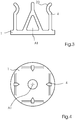
- FIG. 3 shows that the first coupling half 1 has a set of spring jaws 4, which are uniformly distributed about the axis of rotation A1 of the first coupling half 1.
- Each spring claw 4 consists of a spring arm and a driving claw whose cutting edge has a curve 23 inwards.
- the curves 23 roll on the second coupling half 2 and together form a kind of ball joint or universal joint.
- the first coupling half 1 is the joint socket and the second coupling half 2 is the joint head of the compensating coupling 3.
- the second coupling half 2 is a gear with a toothing 5, especially a straight toothing, on the outer circumference. Seen in the axial direction, the second Coupling half 2 the shape of a star.
- the compensating coupling 3 acts as a quick coupling, wherein the operator is the first coupling half 1 without tools plugged onto the second coupling half 2 to connect the screw 11 to the motor M.
- the spring claws 4 are radially flexible and spread apart when plugging something.
- the toothing 5 has a length L which is greater than the maximum travel of the screw 11 between its lowest and highest screw-in position or end position. Thus, the spring claws 4 remain in each screwed position of the screw 11 in engagement with the toothing 5; a compensation for axial displacement of a relative to the other coupling half 1, 2 is given.
- FIG. 4 shows that the first coupling half 1 comprises four spring claws 4, which are arranged in pairs, with the two spring claws 4 of each pair are diametrically opposed.
- FIG. 5 shows a modification with FIG. 4 doubled number of spring clips 4.
- FIG. 6 shows a further modification in which the number of spring claws 4 has been further increased and these are distributed unevenly along the circumference.
- FIG. 7 shows a modification in which the number of spring claws 4 is almost as large as the number of teeth 7 of the gearing 5.
- the flank angle ⁇ of the spring claws 4 can be designed so that in the torque transmission self-locking due to edge friction between the spring claws 4 and the teeth 7 occurs, so that the spring claws 4 can not be moved out of engagement by the centrifugal force.
Landscapes
- Engineering & Computer Science (AREA)
- General Engineering & Computer Science (AREA)
- Mechanical Engineering (AREA)
- Ink Jet (AREA)
- Common Mechanisms (AREA)
- Character Spaces And Line Spaces In Printers (AREA)
- Accessory Devices And Overall Control Thereof (AREA)
Abstract
Description
- Vorliegende Erfindung betrifft eine Ausgleichskupplung, umfassend eine erste und zweite Kupplungshälfte, die unter elastischer Verformung ineinandersteckbar sind.
- In
DE 38 43 825 C1 ist ein allseitig bewegliches Gelenk für Gestänge und Gelenkwellen beschrieben, welches aus zwei identisch ausgebildeten Teilen aus einem elastisch verformbaren Kunststoff besteht, wobei die identisch ausgebildeten Kupplungsglieder mit einer Winkelversetzung von 90° unter federnder elastischer Verformung ineinandersteckbar sind. Dieses Gelenk ist auch als Schnellkupplung in Gestängen oder dergleichen verwendbar, insbesondere wenn solche Gestänge ein allseitig bewegliches Gelenk zur Kompensation von Auslenkbewegungen erforderlich machen. Das Gelenk ist unter anderem in Druckmaschinen verwendbar. - Ungünstig daran ist, dass durch die Winkelversetzung von 90° das Ineinanderstecken der beiden Kupplungsglieder in nur wenigen Winkelstellungen relativ zueinander möglich ist.
- Deshalb ist die Kupplung des Standes der Technik nicht geeignet für einen Einsatz in einer Digitaldruckmaschine mit einem Druckbalken, dessen Justiervorrichtung Bauteile enthält, die in sehr vielen verschiedenen Winkelstellungen relativ zueinander kuppelbar sein müssen. Bei diesen Bauteilen kann es sich z.B. um eine Schraube und eine Welle zum Rotieren der Schraube handeln.
- Aufgabe der Erfindung ist, eine Ausgleichskupplung zu schaffen, deren Kupplungshälften in mehr Winkelstellungen relativ zueinander kuppelbar sind. Außerdem ist es Aufgabe, einen Druckbalken mit einer solchen Ausgleichskupplung zu schaffen.
- Die Aufgabe wird durch eine Ausgleichskupplung mit den Merkmalen des Anspruchs 1 und durch einen Druckbalken mit den Merkmalen des Anspruchs 8 gelöst.
- Die erfindungsgemäße Ausgleichskupplung umfasst eine erste Kupplungshälfte und eine zweite Kupplungshälfte, die unter elastischer Verformung ineinandersteckbar sind, und ist dadurch gekennzeichnet, dass die erste Kupplungshälfte Federklauen und die zweite Kupplungshälfte eine Verzahnung aufweist, wobei die Federklauen eine andere Teilung als die Verzahnung aufweisen.
- Ein Zusatzvorteil der Erfindung ist, dass das Spiel in der Ausgleichskupplung minimiert ist.
- Es sind verschiedene Weiterbildungen der erfindungsgemäßen Ausgleichskupplung möglich:
Die erste Kupplungshälfte kann als Rad ausgebildet sein und die Federklauen können radial einfedern.
Die zweite Kupplungshälfte kann als Stern ausgebildet sein.
Die Verzahnung kann eine bestimmte Länge für einen axialen Ausgleich aufweisen.
Es kann vorgesehen sein, dass die Federklauen das Drehmoment übertragen und einen Ausgleich von Fluchtungsfehlern oder -abweichungen zwischen Rotationsachsen der Kupplungshälften bezüglich Achswinkel und/oder radialem Achsversatz bewirken.
Die Anzahl von Zähnen der Verzahnung kann größer als die Anzahl der Federklauen sein. Bei ineinandergesteckten Kupplungshälften kann eine Teilmenge der Federklauen in Lücken der Verzahnung eingreifen und eine andere Teilmenge der Federklauen nicht in die Lücken der Verzahnung eingreifen. - Der erfindungsgemäße Druckbalken für Inkjet, umfasst Druckköpfe in einer Reihe, Justiereinrichtungen zur Justage der Druckköpfe zueinander, wobei die Justiereinrichtungen jeweils mindestens eine Schraube und mindestens eine Welle zum Rotieren der Schraube aufweisen, und ist dadurch gekennzeichnet, dass die Schraube und die Welle über die erfindungsgemäße oder eine ihrer Weiterbildungen entsprechende Ausgleichskupplung miteinander verbunden sind. Die Ausgleichskupplung des erfindungsgemäßen Druckbalkens umfasst also die erste Kupplungshälfte und die zweite Kupplungshälfte, die unter elastischer Verformung ineinandersteckbar sind, wobei die erste Kupplungshälfte die Federklauen aufweist und die zweite Kupplungshälfte die Verzahnung aufweist, und wobei die Federklauen eine andere Teilung als die Verzahnung aufweisen.
- Verschiedene Weiterbildungen des erfindungsgemäßen Druckbalkens sind möglich:
Die zweite Kupplungshälfte kann an der Schraube angeordnet sein und die erste Kupplungshälfte kann an der Welle angeordnet sein.
Die Welle kann eine Motorwelle eines Motors sein. - Weiterbildungen der Erfindung ergeben sich auch aus der nachfolgenden Beschreibung von Ausführungsbeispielen und der dazugehörigen Zeichnung, in welcher zeigt:
- Figur 1:
- die Gesamtdarstellung einer Digitaldruckmaschine mit einem Druckbalken,
- Figur 2:
- die Detaildarstellung einer Justiereinrichtung des Druckbalkens mit einer Ausgleichskupplung,
- Figur 3:
- die Seitenansicht einer ersten Kupplungshälfte der Ausgleichskupplung aus
Figur 2 , - Figur 4:
- die Draufsicht auf die erste Kupplungshälfte aus
Figur 3 und - Figuren 5 bis 7:
- die Draufsicht auf verschiedene Modifikationen der ersten Kupplungshälfte und auf eine zweite Kupplungshälfte der Ausgleichskupplung aus
Figur 2 . - In den
Figuren 1 bis 7 sind einander entsprechende Bauteile und Elemente mit den gleichen Bezugszeichen bezeichnet. - In
Figur 1 ist eine Digitaldruckmaschine dargestellt, in der Bogen durch Zylinder von einem Anleger über mehrere Stationen zu einem Ausleger transportiert werden. Eine Station umfasst baugleiche Druckbalken 13 für den seitenbreiten Mehrfarbendruck per Inkjet. Jeder Druckbalken 13 druckt eine andere Farbe. - Jeder Druckbalken 13 trägt eine Reihe von Druckköpfen 9 - vgl.
Figur 2 - , die sich über die Breite der Bogen erstreckt. Die Druckköpfe 9 sind mit Düsen (nicht gezeigt) ausgestattet, aus denen die Tinte ausgestoßen wird. Jedem Druckkopf 9 ist eine Justiereinrichtung 10 mit einem Anschlag 15 und einer Feder 16 zugeordnet. Die Justiervorrichtungen 10 dienen dazu, die Druckköpfe 9 relativ zueinander zu verstellen, was im gegebenen Beispiel entlang des Druckbalkens 13 linear erfolgt. Es wäre aber auch eine andere Stellrichtung, z.B. in Bogentransportrichtung, oder eine andere Stellbewegungsform, z.B. eine Schwenkbewegung, möglich. - In
Figur 2 ist einer der Druckköpfe 9 und eine der Justiereinrichtungen 10 dargestellt. Der Anschlag 15 ist über eine Ausgleichskupplung 3 mit einem elektrischen Motor M gekoppelt, der an einem Gestell 17 befestigt ist. Der Motor M ist vorzugsweise ein Schrittmotor. Der Druckkopf 9 wird von einem Halter 18 getragen, der am Anschlag 15 anliegt. Es wäre aber auch möglich, dass direkt der Druckkopf 9 selbst am Anschlag 15 anliegt. Der Anschlag 15 ist als Konus ausgebildet und bildet einen Abschnitt einer Schraube 11. Die Schraube 11 kann auch als Stellwelle oder Konuswelle bezeichnet werden. - Außer dem Anschlag 15 hat die Schraube 11 weitere Abschnitte, nämlich Passungen 19 als Gleitlager und ein Außengewinde 20. Der Anschlag 15 befindet sich zwischen den Passungen 19. Die Passungen 19 sitzen gleitend in einem oder mehreren Bauteilen 21. Das Bauteil 21 hat ein Innengewinde 22, in welches das Außengewinde 20 eingeschraubt ist, wobei die Schraube 11 und das Bauteil 21 zusammen ein Schraubengetriebe zum translatorischen Verstellen des Anschlags 15 in Richtung x bilden. Richtung x entspricht der Rotationsachse der Schraube 11.
- Der Druckkopf 9 oder sein Halter 18 bildet zusammen mit dem Anschlag 15 ein Keilgetriebe, welches die Bewegung des Anschlags 15 in Richtung x in eine Bewegung des Druckkopfes 9 in Richtung y umwandelt, die senkrecht zur Richtung x ist.
- Entsprechend
Figur 2 bewirkt eine Verstellung des Anschlags 15 nach unten, dass der Anschlag 15 den Druckkopf 9 gegen die Wirkung der Feder 16 nach links drückt. Eine Verstellung des Anschlags 15 nach oben bewirkt, dass Freiraum für eine Verstellung des Druckkopfs 9 durch die Feder 16 nach rechts vom Anschlag 15 freigegeben wird. - Der Motor M rotiert über die Ausgleichskupplung 3 die Schraube 11 und schraubt diese dabei ja nach Verstellrichtung etwas tiefer in das Bauteil 21 oder aus diesem etwas heraus. Durch die Ausgleichskupplung 3 ist die Schraube 11 mit einer Welle 12 verbunden, welche die Motorwelle des Motors M ist, wenn - wie im vorliegenden Beispiel - eine motorische Verstellung der Schraube 11 vorgesehen ist. Möglich wäre aber auch eine manuelle Verstellung der Schraube 11, wozu an der Welle 12 statt des Motors M ein Handgriff, z.B. ein Drehknopf, befestigt wäre. Die Ausgleichskupplung 3 umfasst eine erste Kupplungshälfte 1 und eine zweite Kupplungshälfte 2, wobei im gekuppelten Zustand die beiden Kupplungshälften 1, 2 miteinander drehstarr verbunden sind.
- Die erste Kupplungshälfte 1 kann an auf der der Welle 12 fest sitzen oder daran angeformt sein. Die zweite Kupplungshälfte 2 kann auf der Schraube 11 fest sitzen oder daran angeformt sein. Die zweite Kupplungshälfte 2 kann einen Kopf am Ende der Schraube 11 bilden.
-
Figur 3 zeigt, dass die erste Kupplungshälfte 1 einen Satz von Federklauen 4 aufweist, die um die Rotationsachse A1 der ersten Kupplungshälfte 1 gleichverteilt sind. Jede Federklaue 4 besteht aus einem Federarm und einer Mitnehmerklaue, deren Schneide eine Rundung 23 nach innen aufweist. Durch die Rundungen 23 an den Federklauen 4 wird ein Winkelausgleich zwischen den Rotationsachsen A1, A2 der Kupplungshälften 1, 2 ermöglicht. Dabei wälzen die Rundungen 23 auf der zweiten Kupplungshälfte 2 ab und bilden sie zusammen eine Art Kugelgelenk oder Kreuzgelenk. Die erste Kupplungshälfte 1 ist die Gelenkpfanne und die zweite Kupplungshälfte 2 der Gelenkkopf der Ausgleichskupplung 3. - Die zweite Kupplungshälfte 2 ist ein Zahnrad mit einer Verzahnung 5, speziell einer Geradverzahnung, auf dem Außenumfang. In axialer Blickrichtung gesehen hat die zweite Kupplungshälfte 2 die Form eines Sterns. Die Ausgleichskupplung 3 fungiert als Schnellkupplung, wobei vom Bediener die erste Kupplungshälfte 1 werkzeuglos auf die zweite Kupplungshälfte 2 aufgesteckt wird, um die Schraube 11 mit dem Motor M zu verbinden. Die Federklauen 4 sind radial flexibel und spreizen sich beim Aufstecken etwas voneinander. Die Verzahnung 5 hat eine Länge L, die größer als der maximale Stellweg der Schraube 11 zwischen ihrer tiefsten und höchsten Einschraubposition oder Endposition ist. Somit bleiben die Federklauen 4 in jeder Einschraubposition der Schraube 11 im Eingriff in die Verzahnung 5; ein Ausgleich bei axialer Verschiebung der einen relativ zur anderen Kupplungshälfte 1, 2 ist gegeben.
-
Figur 4 zeigt, dass die erste Kupplungshälfte 1 vier Federklauen 4 umfasst, die paarweise angeordnet sind, wobei sich die beiden Federklauen 4 jedes Paares diametral gegenüberliegen. -
Figur 5 zeigt eine Modifikation mit gegenüberFigur 4 verdoppelter Anzahl von Federklauen 4. -
Figur 6 zeigt eine weitere Modifikation, bei der die Anzahl der Federklauen 4 noch weiter erhöht worden ist und diese entlang des Umfangs ungleichmäßig verteilt sind. -
Figur 7 zeigt eine Modifikation, bei der die Anzahl der Federklauen 4 fast so groß wie die Anzahl von Zähnen 7 der Verzahnung 5 ist. - Bei allen Ausführungsbeispielen in den
Figuren 2 bis 7 beträgt die Anzahl der Federklauen 4 weniger als die Anzahl der Zähne 7. Somit sind die Teilung der Verzahnung 5 und die Teilung der Federklauen 4 voneinander verschieden. Durch die ungleichen Teilungen ist sichergestellt, dass es in jeder Drehwinkelposition der ersten Kupplungshälfte 1 relativ zur zweiten Kupplungshälfte 2 eine oder vorzugsweise mehrere Federklauen 4 gibt, die in Lücken 8 zwischen den Zähnen 7 der Verzahnung 5 voll einrasten, und eine oder mehrere Federklauen 4 gibt, die in die Lücken 8 nur teilweise einrasten, und/oder eine oder mehrere Federklauen 4 gibt, die in die Lücken 8 gar nicht einrasten und an den Spitzen der Zähne 7 anliegen. Dadurch ist eine spielfreie und sichere Übertragung des Drehmoments möglich. - Der Flankenwinkel α der Federklauen 4 kann so ausgelegt sein, dass bei der Drehmomentübertragung Selbsthemmung aufgrund von Flankenreibung zwischen den Federklauen 4 und den Zähnen 7 auftritt, so dass die Federklauen 4 durch die Fliehkraft nicht außer Eingriff bewegt werden können.
-
- 1
- erste Kupplungshälfte
- 2
- zweite Kupplungshälfte
- 3
- Ausgleichskupplung
- 4
- Federklaue
- 5
- Verzahnung
- 6
- -
- 7
- Zahn
- 8
- Lücke
- 9
- Druckkopf
- 10
- Justiereinrichtung
- 11
- Schraube
- 12
- Welle
- 13
- Druckbalken
- 14
- -
- 15
- Anschlag
- 16
- Feder
- 17
- Gestell
- 18
- Halter
- 19
- Passung
- 20
- Außengewinde
- 21
- Bauteil
- 22
- Innengewinde
- 23
- Rundung
- A1
- Rotationsachse (der ersten Kupplungshälfte 1)
- A2
- Rotationsachse (der zweiten Kupplungshälfte 2)
- L
- Länge
- M
- Motor
- x
- Richtung
- y
- Richtung
- α
- Flankenwinkel
Claims (10)
- Ausgleichskupplung (3), umfassend eine erste Kupplungshälfte (1) und eine zweite Kupplungshälfte (2), die unter elastischer Verformung ineinandersteckbar sind,
dadurch gekennzeichnet,
dass die erste Kupplungshälfte (1) Federklauen (4) und die zweite Kupplungshälfte (2) eine Verzahnung (5) aufweist, wobei die Federklauen (4) eine andere Teilung als die Verzahnung (5) aufweisen. - Ausgleichskupplung nach Anspruch 1,
dadurch gekennzeichnet,
dass die erste Kupplungshälfte (1) als Rad ausgebildet ist und die Federklauen (4) radial einfedern. - Ausgleichskupplung nach Anspruch 1 oder 2,
dadurch gekennzeichnet,
dass die zweite Kupplungshälfte (2) als Stern ausgebildet ist. - Ausgleichskupplung nach einem der Ansprüche 1 bis 3,
dadurch gekennzeichnet,
dass die Verzahnung (5) eine bestimmte Länge (L) für einen axialen Ausgleich aufweist. - Ausgleichskupplung nach einem der Ansprüche 1 bis 4,
dadurch gekennzeichnet,
dass die Federklauen (4) das Drehmoment übertragen und einen Ausgleich von Fluchtungsabweichungen zwischen Rotationsachsen (A1, A2) der Kupplungshälften (1, 2) bezüglich Achswinkel und/oder radialem Achsversatz bewirken. - Ausgleichskupplung nach einem der Ansprüche 1 bis 5,
dadurch gekennzeichnet,
dass die Anzahl von Zähnen (7) der Verzahnung (5) größer als die Anzahl der Federklauen (4) ist. - Ausgleichskupplung nach einem der Ansprüche 1 bis 6,
dadurch gekennzeichnet,
dass bei ineinandergesteckten Kupplungshälften (1, 2) von den Federklauen (4) eine Teilmenge in Lücken (8) der Verzahnung (5) eingreift und eine andere Teilmenge nicht. - Druckbalken (13) für Inkjet, umfassend Druckköpfe (9) in einer Reihe, Justiereinrichtungen (10) zur Justage der Druckköpfe (9) zueinander, wobei die Justiereinrichtungen (10) jeweils mindestens eine Schraube (11) und mindestens eine Welle (12) zum Rotieren der Schraube (11) aufweisen,
dadurch gekennzeichnet,
dass die Schraube (11) und die Welle (12) über die Ausgleichskupplung (3) nach einem der Ansprüche 1 bis 7 miteinander verbunden sind. - Druckbalken nach Anspruch 8,
dadurch gekennzeichnet,
dass die zweite Kupplungshälfte (2) an der Schraube (11) und die erste Kupplungshälfte (1) an der Welle (12) angeordnet ist. - Druckbalken nach Anspruch 8 oder 9,
dadurch gekennzeichnet,
dass die Welle (12) eine Motorwelle eines Motors (M) ist.
Priority Applications (4)
| Application Number | Priority Date | Filing Date | Title |
|---|---|---|---|
| EP18163049.2A EP3543555A1 (de) | 2018-03-21 | 2018-03-21 | Ausgleichskupplung und druckbalken mit einer solchen ausgleichskupplung |
| CN201910007902.0A CN110296156B (zh) | 2018-03-21 | 2019-01-04 | 补偿联接器和具有这种补偿联接器的印刷梁 |
| US16/298,014 US11415182B2 (en) | 2018-03-21 | 2019-03-11 | Print bar with compensation coupling |
| JP2019052745A JP7206139B2 (ja) | 2018-03-21 | 2019-03-20 | 補償継手およびこのような補償継手を備えた印刷バー |
Applications Claiming Priority (1)
| Application Number | Priority Date | Filing Date | Title |
|---|---|---|---|
| EP18163049.2A EP3543555A1 (de) | 2018-03-21 | 2018-03-21 | Ausgleichskupplung und druckbalken mit einer solchen ausgleichskupplung |
Publications (1)
| Publication Number | Publication Date |
|---|---|
| EP3543555A1 true EP3543555A1 (de) | 2019-09-25 |
Family
ID=61731671
Family Applications (1)
| Application Number | Title | Priority Date | Filing Date |
|---|---|---|---|
| EP18163049.2A Pending EP3543555A1 (de) | 2018-03-21 | 2018-03-21 | Ausgleichskupplung und druckbalken mit einer solchen ausgleichskupplung |
Country Status (4)
| Country | Link |
|---|---|
| US (1) | US11415182B2 (de) |
| EP (1) | EP3543555A1 (de) |
| JP (1) | JP7206139B2 (de) |
| CN (1) | CN110296156B (de) |
Families Citing this family (1)
| Publication number | Priority date | Publication date | Assignee | Title |
|---|---|---|---|---|
| FR3148634B1 (fr) * | 2023-05-09 | 2025-05-23 | Nexter Systems | Pièce d'accouplement et dispositif d'accouplement mécanique la comprenant |
Citations (13)
| Publication number | Priority date | Publication date | Assignee | Title |
|---|---|---|---|---|
| US2706388A (en) * | 1952-09-17 | 1955-04-19 | Borg Warner | Slip clutch assembly |
| CA532026A (en) * | 1956-10-23 | Yates Herbert | Overload-slipping couplings for shafts for transmitting rotary motion | |
| US2861437A (en) * | 1957-10-25 | 1958-11-25 | Sterling Prec Corp | Precision coupling device |
| US3335580A (en) * | 1965-10-22 | 1967-08-15 | Gen Motors Corp | Arcuately indexable rotary drive connector |
| US3385407A (en) * | 1966-01-10 | 1968-05-28 | Veeder Industries Inc | Clutch mechanism for counter drive |
| US4878880A (en) * | 1987-08-20 | 1989-11-07 | Itt Corporation | Clutch apparatus |
| DE3843825C1 (de) | 1988-12-24 | 1990-02-08 | Lemfoerder Metallwaren Ag, 2844 Lemfoerde, De | |
| US5000721A (en) * | 1987-08-20 | 1991-03-19 | Itt Corporation | Clutch apparatus |
| DE102011084748A1 (de) * | 2010-11-12 | 2012-05-16 | Schaeffler Technologies Gmbh & Co. Kg | Kupplungsvorrichtung |
| DE102011015642A1 (de) * | 2011-03-31 | 2012-10-04 | Schaeffler Technologies Gmbh & Co. Kg | Nachstelleinrichtung für eine Reibungskupplung |
| DE102011018319A1 (de) * | 2011-04-20 | 2012-10-25 | Schaeffler Technologies AG & Co. KG | Nachstelleinrichtung für eine Reibungskupplung |
| US20130126289A1 (en) * | 2011-11-22 | 2013-05-23 | Cal-Comp Electronics & Communication Company Limited | Gear clutch assembly and electronic device using the same |
| EP2918374A1 (de) * | 2014-03-10 | 2015-09-16 | Jakoubek Medizintechnik Gmbh | Drehmomentbegrenzungsvorrichtung |
Family Cites Families (21)
| Publication number | Priority date | Publication date | Assignee | Title |
|---|---|---|---|---|
| US5374993A (en) * | 1991-10-01 | 1994-12-20 | Xerox Corporation | Image skew adjustment for a raster output scanning (ROS) system |
| JP3231856B2 (ja) * | 1991-10-31 | 2001-11-26 | 株式会社リコー | 画像形成装置 |
| JPH0732592A (ja) * | 1993-07-19 | 1995-02-03 | Canon Inc | インクジェット記録装置および該装置用記録ヘッド |
| JPH1035021A (ja) * | 1996-07-22 | 1998-02-10 | Olympus Optical Co Ltd | 複数記録ヘッドを用いたカラー画像形成装置 |
| JP3848026B2 (ja) * | 1999-09-03 | 2006-11-22 | キヤノン株式会社 | 液体噴射ヘッドユニット |
| JP3637345B1 (ja) * | 2003-09-24 | 2005-04-13 | ハマダ印刷機械株式会社 | ラインドット記録装置 |
| JP3998679B2 (ja) * | 2004-11-08 | 2007-10-31 | ハマダ印刷機械株式会社 | ラインドット記録装置 |
| US7397493B2 (en) * | 2005-09-23 | 2008-07-08 | Lexmark International, Inc. | Laser printhead having a mechanical skew correction mechanism |
| DE102009005742B4 (de) * | 2008-02-13 | 2015-10-22 | Schaeffler Technologies AG & Co. KG | Reibungskupplung mit Nachstelleinrichtung |
| JP4513874B2 (ja) * | 2008-02-25 | 2010-07-28 | セイコーエプソン株式会社 | 印刷ヘッドのキャリッジへの取り付け位置の調整が可能な印刷装置 |
| JP2009262540A (ja) * | 2008-04-01 | 2009-11-12 | Olympus Corp | 記録ヘッドの位置調整機構及びその位置調整機構を搭載する画像記録装置 |
| JP2010030221A (ja) * | 2008-07-30 | 2010-02-12 | Seiko Epson Corp | ヘッド傾き調整装置、及び液体噴射装置 |
| JP2012161961A (ja) * | 2011-02-04 | 2012-08-30 | Olympus Corp | インクジェットプリンタ |
| JP5978812B2 (ja) * | 2012-07-09 | 2016-08-24 | 株式会社リコー | ヘッドユニット及び画像形成装置 |
| DE112015001475A5 (de) * | 2014-03-27 | 2016-12-01 | Schaeffler Technologies AG & Co. KG | Spindelhalterung für eine Nachstelleinrichtung |
| JP5940183B2 (ja) * | 2015-02-02 | 2016-06-29 | 富士フイルム株式会社 | 液滴吐出ヘッド、画像形成装置、及び、液滴吐出ヘッドのヘッドモジュール位置決め方法 |
| JP6581832B2 (ja) * | 2015-07-29 | 2019-09-25 | 理想科学工業株式会社 | インクジェット印刷装置 |
| JP2017030166A (ja) * | 2015-07-29 | 2017-02-09 | 理想科学工業株式会社 | インクジェット印刷装置 |
| DE102016208079A1 (de) * | 2015-09-16 | 2017-03-16 | Heidelberger Druckmaschinen Ag | Verfahren zur Kollisionsvermeidung, zur Anpassung des Abstandes und zur aktorischen Hubbewegung |
| JP2017104984A (ja) * | 2015-12-07 | 2017-06-15 | コニカミノルタ株式会社 | ヘッドユニット、インクジェット記録装置及び記録ヘッドの位置調整方法 |
| JP2017209814A (ja) * | 2016-05-23 | 2017-11-30 | 株式会社リコー | 画像形成装置および画像形成方法 |
-
2018
- 2018-03-21 EP EP18163049.2A patent/EP3543555A1/de active Pending
-
2019
- 2019-01-04 CN CN201910007902.0A patent/CN110296156B/zh active Active
- 2019-03-11 US US16/298,014 patent/US11415182B2/en active Active
- 2019-03-20 JP JP2019052745A patent/JP7206139B2/ja active Active
Patent Citations (13)
| Publication number | Priority date | Publication date | Assignee | Title |
|---|---|---|---|---|
| CA532026A (en) * | 1956-10-23 | Yates Herbert | Overload-slipping couplings for shafts for transmitting rotary motion | |
| US2706388A (en) * | 1952-09-17 | 1955-04-19 | Borg Warner | Slip clutch assembly |
| US2861437A (en) * | 1957-10-25 | 1958-11-25 | Sterling Prec Corp | Precision coupling device |
| US3335580A (en) * | 1965-10-22 | 1967-08-15 | Gen Motors Corp | Arcuately indexable rotary drive connector |
| US3385407A (en) * | 1966-01-10 | 1968-05-28 | Veeder Industries Inc | Clutch mechanism for counter drive |
| US5000721A (en) * | 1987-08-20 | 1991-03-19 | Itt Corporation | Clutch apparatus |
| US4878880A (en) * | 1987-08-20 | 1989-11-07 | Itt Corporation | Clutch apparatus |
| DE3843825C1 (de) | 1988-12-24 | 1990-02-08 | Lemfoerder Metallwaren Ag, 2844 Lemfoerde, De | |
| DE102011084748A1 (de) * | 2010-11-12 | 2012-05-16 | Schaeffler Technologies Gmbh & Co. Kg | Kupplungsvorrichtung |
| DE102011015642A1 (de) * | 2011-03-31 | 2012-10-04 | Schaeffler Technologies Gmbh & Co. Kg | Nachstelleinrichtung für eine Reibungskupplung |
| DE102011018319A1 (de) * | 2011-04-20 | 2012-10-25 | Schaeffler Technologies AG & Co. KG | Nachstelleinrichtung für eine Reibungskupplung |
| US20130126289A1 (en) * | 2011-11-22 | 2013-05-23 | Cal-Comp Electronics & Communication Company Limited | Gear clutch assembly and electronic device using the same |
| EP2918374A1 (de) * | 2014-03-10 | 2015-09-16 | Jakoubek Medizintechnik Gmbh | Drehmomentbegrenzungsvorrichtung |
Also Published As
| Publication number | Publication date |
|---|---|
| JP2019166833A (ja) | 2019-10-03 |
| CN110296156B (zh) | 2022-05-24 |
| JP7206139B2 (ja) | 2023-01-17 |
| CN110296156A (zh) | 2019-10-01 |
| US11415182B2 (en) | 2022-08-16 |
| US20190293127A1 (en) | 2019-09-26 |
Similar Documents
| Publication | Publication Date | Title |
|---|---|---|
| DE19614397C2 (de) | Antrieb mit Registervorrichtung für eine Druckeinheit einer Rollenrotationsdruckmaschine | |
| DE10215705A1 (de) | Zylindrischer Körper einer bedruckstoffverarbeitenden Maschine | |
| CH686424A5 (de) | Vielfarben-Druckpresse. | |
| EP0894623A2 (de) | Druckwerk für eine Rollenrotationsdruckmaschine | |
| EP0377860B1 (de) | Bogenführungstrommel für Druckmaschinen zum Schön- bzw. Schön- und Widerdruck | |
| EP3527390B1 (de) | Vorrichtung zur justage eines druckkopfs | |
| DE19715026B4 (de) | Elastischer Antrieb für Druckmaschinen | |
| DE3821324A1 (de) | Bogengreifer an bogenrotationsdruckmaschinen | |
| EP3543555A1 (de) | Ausgleichskupplung und druckbalken mit einer solchen ausgleichskupplung | |
| DE102018219826A1 (de) | Druckkopf-Justagevorrichtung und Druckbalken | |
| AT521960B1 (de) | Kupplungselement | |
| EP3350017B1 (de) | Kopfstütze für einen fahrzeugsitz und system zur bildung einer in eine kopfstütze integrierbaren ausrichtungsvorrichtung | |
| DE19543774C2 (de) | Vorrichtung zum zentralen Verstellen von Bogenführungselementen einer Bogenrotationsdruckmaschine | |
| DE2547090C3 (de) | Presse | |
| EP0508113B1 (de) | Vorrichtung zum lagegenauen Schnellklemmen und Spannen von Druckplatten auf dem Plattenzylinder von Druckmaschinen | |
| DE10219840B4 (de) | Antriebseinheit zur Erzeugung von Linear- und Rotationsbewegungen | |
| EP1984181B1 (de) | Formzylinderankopplung | |
| DE10051367B4 (de) | Abkantvorrichtung | |
| DE19718140C1 (de) | Vorrichtung zum lösbaren Verbinden eines Zahnradringes mit dem Hauptzahnrad | |
| DE19616423C2 (de) | Einrichtung zum Wechseln von Bogenbremsen | |
| DE102007043319B4 (de) | Vorrichtung zur Übertragung eines Drehmoments auf eine Welle | |
| DE4140022C2 (de) | Vorrichtung zum Spannen einer Druckplatte auf einen Plattenzylinder einer Druckmaschine | |
| EP1451088A2 (de) | R derfalzapparat | |
| DE1525388A1 (de) | Flexible Kupplung | |
| DE2207972C3 (de) | Einrichtung zum spaltengerechten Einstellen eines Typenträgers |
Legal Events
| Date | Code | Title | Description |
|---|---|---|---|
| PUAI | Public reference made under article 153(3) epc to a published international application that has entered the european phase |
Free format text: ORIGINAL CODE: 0009012 |
|
| STAA | Information on the status of an ep patent application or granted ep patent |
Free format text: STATUS: THE APPLICATION HAS BEEN PUBLISHED |
|
| AK | Designated contracting states |
Kind code of ref document: A1 Designated state(s): AL AT BE BG CH CY CZ DE DK EE ES FI FR GB GR HR HU IE IS IT LI LT LU LV MC MK MT NL NO PL PT RO RS SE SI SK SM TR |
|
| AX | Request for extension of the european patent |
Extension state: BA ME |
|
| STAA | Information on the status of an ep patent application or granted ep patent |
Free format text: STATUS: REQUEST FOR EXAMINATION WAS MADE |
|
| 17P | Request for examination filed |
Effective date: 20200325 |
|
| RBV | Designated contracting states (corrected) |
Designated state(s): AL AT BE BG CH CY CZ DE DK EE ES FI FR GB GR HR HU IE IS IT LI LT LU LV MC MK MT NL NO PL PT RO RS SE SI SK SM TR |
|
| STAA | Information on the status of an ep patent application or granted ep patent |
Free format text: STATUS: EXAMINATION IS IN PROGRESS |
|
| 17Q | First examination report despatched |
Effective date: 20220620 |
|
| P01 | Opt-out of the competence of the unified patent court (upc) registered |
Effective date: 20230517 |
|
| REG | Reference to a national code |
Ref country code: DE Ref legal event code: R079 Free format text: PREVIOUS MAIN CLASS: F16D0013750000 Ipc: F16D0011100000 |
|
| RIC1 | Information provided on ipc code assigned before grant |
Ipc: F16D 11/10 20060101AFI20230804BHEP |