EP3526419B1 - Dachdeck-, verkleidungs- oder aussenverkleidungsmodul oder vorrichtung - Google Patents
Dachdeck-, verkleidungs- oder aussenverkleidungsmodul oder vorrichtung Download PDFInfo
- Publication number
- EP3526419B1 EP3526419B1 EP17862727.9A EP17862727A EP3526419B1 EP 3526419 B1 EP3526419 B1 EP 3526419B1 EP 17862727 A EP17862727 A EP 17862727A EP 3526419 B1 EP3526419 B1 EP 3526419B1
- Authority
- EP
- European Patent Office
- Prior art keywords
- module
- cavity
- building surface
- angle
- roofing
- Prior art date
- Legal status (The legal status is an assumption and is not a legal conclusion. Google has not performed a legal analysis and makes no representation as to the accuracy of the status listed.)
- Active
Links
Images




Classifications
-
- H—ELECTRICITY
- H02—GENERATION; CONVERSION OR DISTRIBUTION OF ELECTRIC POWER
- H02S—GENERATION OF ELECTRIC POWER BY CONVERSION OF INFRARED RADIATION, VISIBLE LIGHT OR ULTRAVIOLET LIGHT, e.g. USING PHOTOVOLTAIC [PV] MODULES
- H02S40/00—Components or accessories in combination with PV modules, not provided for in groups H02S10/00 - H02S30/00
- H02S40/40—Thermal components
- H02S40/44—Means to utilise heat energy, e.g. hybrid systems producing warm water and electricity at the same time
-
- E—FIXED CONSTRUCTIONS
- E04—BUILDING
- E04D—ROOF COVERINGS; SKY-LIGHTS; GUTTERS; ROOF-WORKING TOOLS
- E04D1/00—Roof covering by making use of tiles, slates, shingles, or other small roofing elements
- E04D1/24—Roofing elements with cavities, e.g. hollow tiles
-
- E—FIXED CONSTRUCTIONS
- E04—BUILDING
- E04D—ROOF COVERINGS; SKY-LIGHTS; GUTTERS; ROOF-WORKING TOOLS
- E04D1/00—Roof covering by making use of tiles, slates, shingles, or other small roofing elements
- E04D1/26—Strip-shaped roofing elements simulating a repetitive pattern, e.g. appearing as a row of shingles
- E04D1/265—Strip-shaped roofing elements simulating a repetitive pattern, e.g. appearing as a row of shingles the roofing elements being rigid, e.g. made of metal, wood or concrete
-
- E—FIXED CONSTRUCTIONS
- E04—BUILDING
- E04D—ROOF COVERINGS; SKY-LIGHTS; GUTTERS; ROOF-WORKING TOOLS
- E04D1/00—Roof covering by making use of tiles, slates, shingles, or other small roofing elements
- E04D1/29—Means for connecting or fastening adjacent roofing elements
- E04D1/2907—Means for connecting or fastening adjacent roofing elements by interfitted sections
- E04D1/2956—Means for connecting or fastening adjacent roofing elements by interfitted sections having tongues and grooves
-
- E—FIXED CONSTRUCTIONS
- E04—BUILDING
- E04D—ROOF COVERINGS; SKY-LIGHTS; GUTTERS; ROOF-WORKING TOOLS
- E04D1/00—Roof covering by making use of tiles, slates, shingles, or other small roofing elements
- E04D1/30—Special roof-covering elements, e.g. ridge tiles, gutter tiles, gable tiles, ventilation tiles
-
- E—FIXED CONSTRUCTIONS
- E04—BUILDING
- E04D—ROOF COVERINGS; SKY-LIGHTS; GUTTERS; ROOF-WORKING TOOLS
- E04D13/00—Special arrangements or devices in connection with roof coverings; Protection against birds; Roof drainage ; Sky-lights
- E04D13/17—Ventilation of roof coverings not otherwise provided for
-
- E—FIXED CONSTRUCTIONS
- E04—BUILDING
- E04D—ROOF COVERINGS; SKY-LIGHTS; GUTTERS; ROOF-WORKING TOOLS
- E04D3/00—Roof covering by making use of flat or curved slabs or stiff sheets
- E04D3/02—Roof covering by making use of flat or curved slabs or stiff sheets of plane slabs, slates, or sheets, or in which the cross-section is unimportant
-
- E—FIXED CONSTRUCTIONS
- E04—BUILDING
- E04D—ROOF COVERINGS; SKY-LIGHTS; GUTTERS; ROOF-WORKING TOOLS
- E04D3/00—Roof covering by making use of flat or curved slabs or stiff sheets
- E04D3/36—Connecting; Fastening
- E04D3/365—Connecting; Fastening by simple overlapping of the marginal portions with use of separate connecting elements, e.g. hooks or bolts for corrugated sheets
-
- E—FIXED CONSTRUCTIONS
- E04—BUILDING
- E04F—FINISHING WORK ON BUILDINGS, e.g. STAIRS, FLOORS
- E04F13/00—Coverings or linings, e.g. for walls or ceilings
- E04F13/007—Outer coverings for walls with ventilating means
-
- E—FIXED CONSTRUCTIONS
- E04—BUILDING
- E04F—FINISHING WORK ON BUILDINGS, e.g. STAIRS, FLOORS
- E04F13/00—Coverings or linings, e.g. for walls or ceilings
- E04F13/07—Coverings or linings, e.g. for walls or ceilings composed of covering or lining elements; Sub-structures therefor; Fastening means therefor
- E04F13/072—Coverings or linings, e.g. for walls or ceilings composed of covering or lining elements; Sub-structures therefor; Fastening means therefor composed of specially adapted, structured or shaped covering or lining elements
- E04F13/074—Coverings or linings, e.g. for walls or ceilings composed of covering or lining elements; Sub-structures therefor; Fastening means therefor composed of specially adapted, structured or shaped covering or lining elements for accommodating service installations or utility lines, e.g. heating conduits, electrical lines, lighting devices or service outlets
-
- E—FIXED CONSTRUCTIONS
- E04—BUILDING
- E04F—FINISHING WORK ON BUILDINGS, e.g. STAIRS, FLOORS
- E04F13/00—Coverings or linings, e.g. for walls or ceilings
- E04F13/07—Coverings or linings, e.g. for walls or ceilings composed of covering or lining elements; Sub-structures therefor; Fastening means therefor
- E04F13/08—Coverings or linings, e.g. for walls or ceilings composed of covering or lining elements; Sub-structures therefor; Fastening means therefor composed of a plurality of similar covering or lining elements
- E04F13/0801—Separate fastening elements
- E04F13/0832—Separate fastening elements without load-supporting elongated furring elements between wall and covering elements
- E04F13/0833—Separate fastening elements without load-supporting elongated furring elements between wall and covering elements not adjustable
- E04F13/0835—Separate fastening elements without load-supporting elongated furring elements between wall and covering elements not adjustable the fastening elements extending into the back side of the covering elements
- E04F13/0837—Separate fastening elements without load-supporting elongated furring elements between wall and covering elements not adjustable the fastening elements extending into the back side of the covering elements extending completely through the covering elements
-
- E—FIXED CONSTRUCTIONS
- E04—BUILDING
- E04F—FINISHING WORK ON BUILDINGS, e.g. STAIRS, FLOORS
- E04F13/00—Coverings or linings, e.g. for walls or ceilings
- E04F13/07—Coverings or linings, e.g. for walls or ceilings composed of covering or lining elements; Sub-structures therefor; Fastening means therefor
- E04F13/08—Coverings or linings, e.g. for walls or ceilings composed of covering or lining elements; Sub-structures therefor; Fastening means therefor composed of a plurality of similar covering or lining elements
- E04F13/0864—Coverings or linings, e.g. for walls or ceilings composed of covering or lining elements; Sub-structures therefor; Fastening means therefor composed of a plurality of similar covering or lining elements composed of superposed elements which overlap each other and of which the flat outer surface includes an acute angle with the surface to cover
-
- E—FIXED CONSTRUCTIONS
- E04—BUILDING
- E04F—FINISHING WORK ON BUILDINGS, e.g. STAIRS, FLOORS
- E04F13/00—Coverings or linings, e.g. for walls or ceilings
- E04F13/07—Coverings or linings, e.g. for walls or ceilings composed of covering or lining elements; Sub-structures therefor; Fastening means therefor
- E04F13/08—Coverings or linings, e.g. for walls or ceilings composed of covering or lining elements; Sub-structures therefor; Fastening means therefor composed of a plurality of similar covering or lining elements
- E04F13/18—Coverings or linings, e.g. for walls or ceilings composed of covering or lining elements; Sub-structures therefor; Fastening means therefor composed of a plurality of similar covering or lining elements of organic plastics with or without reinforcements or filling materials or with an outer layer of organic plastics with or without reinforcements or filling materials; plastic tiles
-
- E—FIXED CONSTRUCTIONS
- E04—BUILDING
- E04F—FINISHING WORK ON BUILDINGS, e.g. STAIRS, FLOORS
- E04F13/00—Coverings or linings, e.g. for walls or ceilings
- E04F13/07—Coverings or linings, e.g. for walls or ceilings composed of covering or lining elements; Sub-structures therefor; Fastening means therefor
- E04F13/21—Fastening means specially adapted for covering or lining elements
- E04F13/24—Hidden fastening means on the rear of the covering or lining elements
-
- F—MECHANICAL ENGINEERING; LIGHTING; HEATING; WEAPONS; BLASTING
- F24—HEATING; RANGES; VENTILATING
- F24S—SOLAR HEAT COLLECTORS; SOLAR HEAT SYSTEMS
- F24S20/00—Solar heat collectors specially adapted for particular uses or environments
- F24S20/60—Solar heat collectors integrated in fixed constructions, e.g. in buildings
- F24S20/67—Solar heat collectors integrated in fixed constructions, e.g. in buildings in the form of roof constructions
-
- H—ELECTRICITY
- H02—GENERATION; CONVERSION OR DISTRIBUTION OF ELECTRIC POWER
- H02S—GENERATION OF ELECTRIC POWER BY CONVERSION OF INFRARED RADIATION, VISIBLE LIGHT OR ULTRAVIOLET LIGHT, e.g. USING PHOTOVOLTAIC [PV] MODULES
- H02S20/00—Supporting structures for PV modules
- H02S20/20—Supporting structures directly fixed to an immovable object
- H02S20/22—Supporting structures directly fixed to an immovable object specially adapted for buildings
- H02S20/26—Building materials integrated with PV modules, e.g. façade elements
-
- E—FIXED CONSTRUCTIONS
- E04—BUILDING
- E04D—ROOF COVERINGS; SKY-LIGHTS; GUTTERS; ROOF-WORKING TOOLS
- E04D1/00—Roof covering by making use of tiles, slates, shingles, or other small roofing elements
- E04D1/30—Special roof-covering elements, e.g. ridge tiles, gutter tiles, gable tiles, ventilation tiles
- E04D2001/309—Ventilation tiles
-
- E—FIXED CONSTRUCTIONS
- E04—BUILDING
- E04D—ROOF COVERINGS; SKY-LIGHTS; GUTTERS; ROOF-WORKING TOOLS
- E04D1/00—Roof covering by making use of tiles, slates, shingles, or other small roofing elements
- E04D1/34—Fastenings for attaching roof-covering elements to the supporting elements
- E04D2001/3408—Fastenings for attaching roof-covering elements to the supporting elements characterised by the fastener type or material
-
- Y—GENERAL TAGGING OF NEW TECHNOLOGICAL DEVELOPMENTS; GENERAL TAGGING OF CROSS-SECTIONAL TECHNOLOGIES SPANNING OVER SEVERAL SECTIONS OF THE IPC; TECHNICAL SUBJECTS COVERED BY FORMER USPC CROSS-REFERENCE ART COLLECTIONS [XRACs] AND DIGESTS
- Y02—TECHNOLOGIES OR APPLICATIONS FOR MITIGATION OR ADAPTATION AGAINST CLIMATE CHANGE
- Y02B—CLIMATE CHANGE MITIGATION TECHNOLOGIES RELATED TO BUILDINGS, e.g. HOUSING, HOUSE APPLIANCES OR RELATED END-USER APPLICATIONS
- Y02B10/00—Integration of renewable energy sources in buildings
- Y02B10/10—Photovoltaic [PV]
-
- Y—GENERAL TAGGING OF NEW TECHNOLOGICAL DEVELOPMENTS; GENERAL TAGGING OF CROSS-SECTIONAL TECHNOLOGIES SPANNING OVER SEVERAL SECTIONS OF THE IPC; TECHNICAL SUBJECTS COVERED BY FORMER USPC CROSS-REFERENCE ART COLLECTIONS [XRACs] AND DIGESTS
- Y02—TECHNOLOGIES OR APPLICATIONS FOR MITIGATION OR ADAPTATION AGAINST CLIMATE CHANGE
- Y02B—CLIMATE CHANGE MITIGATION TECHNOLOGIES RELATED TO BUILDINGS, e.g. HOUSING, HOUSE APPLIANCES OR RELATED END-USER APPLICATIONS
- Y02B10/00—Integration of renewable energy sources in buildings
- Y02B10/20—Solar thermal
-
- Y—GENERAL TAGGING OF NEW TECHNOLOGICAL DEVELOPMENTS; GENERAL TAGGING OF CROSS-SECTIONAL TECHNOLOGIES SPANNING OVER SEVERAL SECTIONS OF THE IPC; TECHNICAL SUBJECTS COVERED BY FORMER USPC CROSS-REFERENCE ART COLLECTIONS [XRACs] AND DIGESTS
- Y02—TECHNOLOGIES OR APPLICATIONS FOR MITIGATION OR ADAPTATION AGAINST CLIMATE CHANGE
- Y02B—CLIMATE CHANGE MITIGATION TECHNOLOGIES RELATED TO BUILDINGS, e.g. HOUSING, HOUSE APPLIANCES OR RELATED END-USER APPLICATIONS
- Y02B10/00—Integration of renewable energy sources in buildings
- Y02B10/70—Hybrid systems, e.g. uninterruptible or back-up power supplies integrating renewable energies
-
- Y—GENERAL TAGGING OF NEW TECHNOLOGICAL DEVELOPMENTS; GENERAL TAGGING OF CROSS-SECTIONAL TECHNOLOGIES SPANNING OVER SEVERAL SECTIONS OF THE IPC; TECHNICAL SUBJECTS COVERED BY FORMER USPC CROSS-REFERENCE ART COLLECTIONS [XRACs] AND DIGESTS
- Y02—TECHNOLOGIES OR APPLICATIONS FOR MITIGATION OR ADAPTATION AGAINST CLIMATE CHANGE
- Y02E—REDUCTION OF GREENHOUSE GAS [GHG] EMISSIONS, RELATED TO ENERGY GENERATION, TRANSMISSION OR DISTRIBUTION
- Y02E10/00—Energy generation through renewable energy sources
- Y02E10/40—Solar thermal energy, e.g. solar towers
-
- Y—GENERAL TAGGING OF NEW TECHNOLOGICAL DEVELOPMENTS; GENERAL TAGGING OF CROSS-SECTIONAL TECHNOLOGIES SPANNING OVER SEVERAL SECTIONS OF THE IPC; TECHNICAL SUBJECTS COVERED BY FORMER USPC CROSS-REFERENCE ART COLLECTIONS [XRACs] AND DIGESTS
- Y02—TECHNOLOGIES OR APPLICATIONS FOR MITIGATION OR ADAPTATION AGAINST CLIMATE CHANGE
- Y02E—REDUCTION OF GREENHOUSE GAS [GHG] EMISSIONS, RELATED TO ENERGY GENERATION, TRANSMISSION OR DISTRIBUTION
- Y02E10/00—Energy generation through renewable energy sources
- Y02E10/40—Solar thermal energy, e.g. solar towers
- Y02E10/44—Heat exchange systems
-
- Y—GENERAL TAGGING OF NEW TECHNOLOGICAL DEVELOPMENTS; GENERAL TAGGING OF CROSS-SECTIONAL TECHNOLOGIES SPANNING OVER SEVERAL SECTIONS OF THE IPC; TECHNICAL SUBJECTS COVERED BY FORMER USPC CROSS-REFERENCE ART COLLECTIONS [XRACs] AND DIGESTS
- Y02—TECHNOLOGIES OR APPLICATIONS FOR MITIGATION OR ADAPTATION AGAINST CLIMATE CHANGE
- Y02E—REDUCTION OF GREENHOUSE GAS [GHG] EMISSIONS, RELATED TO ENERGY GENERATION, TRANSMISSION OR DISTRIBUTION
- Y02E10/00—Energy generation through renewable energy sources
- Y02E10/50—Photovoltaic [PV] energy
-
- Y—GENERAL TAGGING OF NEW TECHNOLOGICAL DEVELOPMENTS; GENERAL TAGGING OF CROSS-SECTIONAL TECHNOLOGIES SPANNING OVER SEVERAL SECTIONS OF THE IPC; TECHNICAL SUBJECTS COVERED BY FORMER USPC CROSS-REFERENCE ART COLLECTIONS [XRACs] AND DIGESTS
- Y02—TECHNOLOGIES OR APPLICATIONS FOR MITIGATION OR ADAPTATION AGAINST CLIMATE CHANGE
- Y02E—REDUCTION OF GREENHOUSE GAS [GHG] EMISSIONS, RELATED TO ENERGY GENERATION, TRANSMISSION OR DISTRIBUTION
- Y02E10/00—Energy generation through renewable energy sources
- Y02E10/60—Thermal-PV hybrids
Definitions
- the present technology relates generally to roofing, cladding and/or siding products for providing a covering on a building surface.
- Solar energy is one type of renewable energy source, and the sun's energy can be collected in a variety of different ways.
- One is converting solar energy into thermal energy to heat a fluid, such as air or water.
- Another is converting solar energy to electricity using photovoltaic cells.
- a properly sized and installed solar energy collection system can be a practical alternative for acquiring energy needs.
- roofing and cladding surfaces tend to heat up over periods of exposure to sunlight, and the heat may then be transferred to the interior of the building. This can increase the expense of air conditioning and environmental control. Therefore, various methods of deflecting the heat, for example by providing reflective surfaces, are also known.
- WO2015/132756 discloses a solar thermal control system 100 consisting of an outside cladding forming a cavity with an underlying support material of the building structure. The system is configured to collect heat from solar energy by extracting air from the cavity.
- US 5,615,527 describes a roof tile formed of a sheet metal in which the sheet material tile is strengthened by integral flanges raised bosses and depressions.
- the raised bosses in use act as supports between one tile and an overlapping portion of another tile.
- the present invention consist in a roofing, cladding or siding module according to claim 1.
- each projection is a said foot and an angle between the surface of the cavity and a plane coterminous with bases of the feet is less than an angle of incline of the inclined building surface.
- an angle between the surface of the cavity and the building surface is less than an angle of incline of the inclined building surface.
- the angle of the surface of the cavity is less than 30 degrees, or less than 25 degrees, or less than 20 degrees, or less than 15degrees, or is 10 degrees to 15degrees.
- an angle of a surface of the cavity extending between a base of the cavity and a rear of the cavity is greater than an angle of the surface of the cavity extending between the base of the cavity and the front of the cavity.
- an angle between the surface of the cavity extending between the base of the cavity and a rear of the cavity and the surface extending between the base of the cavity and the front of the cavity is less than 120 degrees.
- the angle or angles is or are relative to a front-to-rear centerline of the cavity.
- the cavity reduces in width towards a front of the cavity to funnel water towards the front of the cavity.
- the cavity reduces in width between the base of the cavity and the front of the cavity.
- the cavity in plan-view is approximately teardrop shaped, a top of the teardrop shape forming the front of the cavity.
- each projection is a said foot and a base of the foot comprises a flat portion to bear against the building surface.
- a corresponding base of the cavity comprises a flat portion.
- the projections create a tortuous pathway for air flow between the building surface and the module.
- the module is a starter module for use at a lower edge of the building surface, the module to be substantially completely overlapped by an exposed region of an adjacent roofing, cladding or siding module.
- the module comprises an exposed region adapted to cover the underlapping region of an adjacent module when installed on the building surface.
- the upper surface of the exposed region comprises a photovoltaic cell or device.
- the module is adapted for use as part of a thermal energy recovery system.
- the module comprises: a projection extending from the exposed region to provide a bearing surface facing the under surface of the exposed region, and one or more location details in the underlapping region each for receiving a clip comprising a tongue adapted to be received between the bearing surface and the under surface of the exposed region of an adjacent overlapping module when installed on a building surface.
- the present invention consists in a roofing, cladding, or siding apparatus according to claim 16
- the present invention consists in a system according to claim 17.
- Relative terms such as “lower” or “bottom”, “upper” or “top,” and “front” or “back” may be used herein to describe one element's relationship to another element as illustrated in the Figures. It will be understood that relative terms are intended to encompass different orientations of the device in addition to the orientation depicted in the Figures. For example, if a device or apparatus in one of the figures is turned over, elements described as being on the “lower” side of other elements would then be oriented on “upper” sides of the other elements. The exemplary term “lower”, therefore, encompasses both an orientation of “lower” and “upper,” depending of the particular orientation of the figure.
- the term "building surface" refers to a wall surface or a top surface, etc. of a building, e.g. an exterior wall, a roof, a ceiling, etc., unless otherwise specified.
- the building surface typically comprises a waterproof roofing membrane attached to the roof deck adjacent an eave of the roof for preventing water damage to the roof deck and an interior of a building from wind-blown rain or water build-up on the roof.
- the roof deck is typically made of an underlying material, such as plywood.
- the waterproof membrane may be any of a number of waterproof roofing membranes known in the art such as but not limited to bituminous waterproof membranes, modified bituminous roofing membranes, self-adhering roofing membranes, or single ply waterproofing roofing membranes (e.g. EPDM waterproof roofing membranes, PVC waterproof roofing membranes, TPO waterproof roofing membranes).
- One exemplary membrane sheet is Deck-Armor TM Roof Protection, manufactured by GAF Corp., Wayne, New Jersey.
- roofing means a protective covering on the roof surface of a building.
- a protective covering might take the form of shingles, tiles, panels, shakes, planks, boards, mouldings or sheets.
- cladding and/or “siding” mean a protective covering on a side or other surface of a building.
- a protective covering might take the form of shingles, tiles, panels, shakes, planks, boards, mouldings or sheets.
- a roofing, cladding and/or siding module that forms part of a roofing cladding or siding of a building may comprise one or more shingles, tiles, panels, shakes, planks, boards, mouldings or sheets or a portion of one of these.
- a cladding or siding module may be a weather board, and a roofing module may be a tile or shingle.
- a roofing, cladding or siding module is moulded from a polymeric material or materials (which may be in layers). Each moulded polymeric module preferably comprises a plurality of three or more dimensional profiled surfaces joined without weld lines or injection moulding points. Each profiled surface is a moulded segment along the length of the module.
- each formed segment may correspond to an individual die or mold of a continuous forming machine.
- the one or more polymeric materials are selected from the group consisting of polycarbonate, foamed polycarbonate, thermoplastic polyurethane (TPU), thermoplastic olefin (TPO), polyvinyl chloride (PVC), acrylonitrite butadiene Styrene (ABS), Styrene-acrylonitrile resin (SAN), thermoplastic rubber, and any other amorphous or crystalline polymer or combination of polymers.
- the one or more polymeric materials are flame retardant.
- the one or more polymeric materials are weather, hail, ultraviolet, tear, mold and impact resistant.
- a roofing, cladding or siding module may be formed from metals, composites, fibre cement, fibreglass, concrete, clay, wood and/or asphalt.
- the terms “profiled” and/or “contoured” mean having a region, or regions which extend above or below a notional planar surface lying along the longitudinal axis of the product. This includes profiling or contouring of only one upper or lower surface, and/or profiling or contouring of an entire thickness of material such that the upper and lower surfaces have the same relative degree of extension above or below the notional planar surface.
- polymer includes polymers, polymer blends, and polymers with or without additive inclusions.
- a solar thermal system is shown in Figure 1 as a roof installation.
- solar thermal system comprising a cladding or external membrane may be mounted or coupled to any underlying support material (e.g., a wall, a roof, etc.) of a building or structure in order to collect solar energy at the structure.
- underlying support material e.g., a wall, a roof, etc.
- the solar thermal system may include a solar collector consisting of an outside cladding or external membrane (e.g., one or more roofing modules) forming a cavity with the underlying support material of the building structure.
- the system is configured to collect heat from solar energy by extracting air from the cavity.
- the solar thermal system also includes a thermal collection unit (e.g., a thermal box) that may be mounted underneath the external membrane and connected to the cavity to collect and direct air flow from the cavity.
- the system may also include ducts (i.e., a ducting system) to direct the flow of air within the solar thermal system.
- the system described herein offers an additional benefit of providing building efficiency (e.g., energy efficiency) by way of reducing thermal load into the building or other associated structure during warm seasons and reducing the escape of thermal energy produced within the building or other structure during cold seasons.
- a solar thermal control system 100 is shown.
- the system 100 may be configured to form an outermost (e.g., topmost) surface of a building or other structure.
- the system 100 includes a roofing membrane 102 configured to cover underlying support material 112 (e.g., building paper, plywood, dry wall, etc.) of an associated building.
- the roofing membrane 102 may be at least partially made from a weatherproofing material in order to protect the structure from the elements, including the underlying material 112.
- the outermost surface of the roofing membrane 102 may be made from a material configured to absorb sunlight, such as a solar panel.
- the roofing membrane 102 is made from a plurality of overlapping sections (e.g., roofing modules, tiles, shingles, etc.), as shown in Figure 3 .
- the roofing membrane 102 is configured to form a cavity 108 for air to flow between the membrane 102 and the underlying material 112.
- the air within the cavity 108 is heated by the sunlight (i.e., the solar energy) captured by the roofing membrane 102.
- the hot air is drawn from the cavity 108 into a thermal collection unit shown as a box 104.
- An exemplary path for the hot air is illustrated by the arrows of Figure 1 .
- the box 104 is fluidly connected to the cavity 108 and configured to receive the hot air from the cavity 108.
- the air is either routed into the building (down according to Figure 1 ) to be used to heat water or the environment within the building or the air is exhausted into the outside air via a vented ridge 106 of the system 100.
- Air may also be otherwise vented from the building in this or other embodiments (e.g., via a duct to an exterior wall such as a gable end).
- the vented ridge 106 is configured to cover a portion of the roofing membrane 102 and provides at least one extraction point shown as opening 114 for excess hot air to be exhausted from the system 100 (e.g., from the box 104).
- the system 100 may include any number of extraction points (e.g., openings, exhaust areas, etc.) in other embodiments. The number of extraction points may depend on the size and/or shape of the roof or the associated building and/or a particular application of the thermal control system 100.
- a fan may be provided to draw or push air up the cavity, and/or from the box 104.
- Each roofing, cladding or siding apparatus comprises a roofing, cladding or siding module 200.
- Each module 200 includes an underlapping section 202 (e.g., bottom section, under section, etc.) and an overlapping section 204 (e.g., top section, over section, etc.).
- the sections 202 and 204 may be made from similar material, and preferably are integrally formed as a single unitary member. In an exemplary embodiment, the sections 202 and 204 have similar dimensions, including a similar area, such that the sections 202 and 204 overlap to form the membrane 102.
- Each module may be fixed to a building surface such as a roof surface by fasteners (nail or screw for example) applied through the module in the underlapping region or fixing region of the module.
- fasteners are applied through the underlapping region so that the fasteners do not penetrate the exposed overlapping region of the module, thereby making the roofing, cladding or siding apparatus less likely to leak.
- the underlapping region may be pre-formed with fastener holes or may include markings for locating or supporting fasteners for penetrating the module.
- the exposed region of the module is also secured to the building surface to ensure the module is properly secured to the building.
- a front edge or front edge portion of the exposed region is secured to the building surface to prevent damage to the module caused by wind lifting a front edge of the module off or away from an underlying module.
- the roofing, cladding or siding apparatus comprises one or more clips 208.
- Each clip 208 secures the exposed region 204 of an adjacent overlapping module 200 to the underlapping module 200.
- Each clip may be located within a location detail on the underlapping region 202.
- the exposed region 204 of the overlapping module is secured to the building surface via the underlapping module.
- the clip is secured to the building surface by a fastener (e.g.
- the fastener and clip secure an underlapping module and an overlapping module to the building surface at a single location of the building surface.
- each clip 208 provides a tongue 209 to be received in a corresponding groove 210 of the exposed region 204 of an adjacent overlapping module 200.
- the module comprises a projection or lip 211 extending rearward from the under surface of the exposed region 204.
- the lip 211 provides a groove or channel 210 between the lip 211 and the under surface 212 of the exposed region 204.
- the groove or channel 210 is open towards the rear of the module for receiving the forwardly extending tongue 209 of a clip 208.
- a 'starter module' may be provided that has an underlapping region 202 and no overlapping region.
- a starter module 300 is illustrated in Figure 5 .
- the starter module 300 may be fixed to a building surface 112, for example a roofing surface, at a lower edge of the surface 112.
- a module 200 in a next row of modules up the building surface is applied with its overlapping section 204 overlapping the starter module 300, and with its front edge 215 secured to the starter module via clips 208.
- the underlapping section 202 of the module 200, 300 includes projections 206. Some of the projections may form feet 206 configured to rest on the underlying material 112 (or another outer surface) of the associated building, raising the remainder of the underlapping section 202 a distance above the underlying material 112. When the feet 206 rest on the underlying material 112, the cavity 108 is formed between the underlapping section 202 and the underlying material 112 (i.e., around or between the feet 206).
- the height of the projections 206 may be related to an intended air flow through the cavity 108, with a greater height leading to a greater air flow.
- the projections 206 are sized and shaped to provide an approximately 20 millimetre air gap between the roofing module 200 and the underlying material 112 (e.g., wherein the feet 206 and/or the cavity have a height of approximately twenty millimetres).
- the air gap e.g., the cavity 108 is intended to allow air to be drawn from either a section (e.g., a roofing module 200) or the whole roof (e.g., the membrane 102) to a centrally located thermal collection unit (e.g., box 104).
- the roof of a building structure may contain a plurality of collection units to optimize thermal energy harvest.
- solar thermal energy may be collected from a first roof surface and directed (e.g., via a system of ducts and dampers) to a second roof surface to melt snow on the second roof surface.
- a first roof surface or section of roof surfaces may be utilized for water heating and a second roof surfaces or section of roof surfaces may be utilized for space heating.
- some of the projections 206 may not act as feet, but may be provided to disrupt or direct air flow through the cavity.
- some projections 206 may act as feet and also as projections for directing air flow, and some projections 206 may provide for directing air flow only, without supporting the module 200 from the building surface.
- the projections 206 are provided in rows that are staggered, to provide a tortuous pathway for the air flow up the cavity between the building surface and membrane.
- the underlapping section 202 may include any number of projections 206 as is suitable for the particular application of the system 100. For instance, the underlapping section 202 may include less projections 206 if a greater air flow is required through the cavity 108 (i.e., to create more air space within the cavity 108). The underlapping section 202 may also include more projections 206 if the roofing modules 200 are made from a particularly heavy material (i.e., to support the weight of the roofing modules 200) or are to be positioned in a relatively high foot- traffic area of the roof (e.g., to support the weight of any service personnel or other persons on the roof). The projections 206 may be approximately equally spaced across the underlapping section 202 in order to raise the underlapping section 202 an appropriate distance above the underlying material 112 and create the cavity 108.
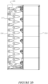
- Each projection 206 is formed by a downwardly projecting portion of the underlapping region 202 with a corresponding cavity 214 in an upper side 213 of the underlapping region 202. If there were to be any water reaching between the exposed region 204 of an overlapping region and the under lapping region of an underlapping module, for example in extreme weather conditions whereby water may be directed upwards up a roofing surface, the water may collect or pool in the cavities in the upper surface of the module. Therefore, according to the present invention, each cavity is shaped to prevent or minimize water pooling in the cavity. As shown in Figure 3 , the roofing membrane 102 is particularly configured for a slanted or angled roof (relative to the horizon).
- Each cavity is preferably shaped to prevent or minimum water pooling in the cavity for a particular angle of inclination of the building surface.
- the cavity is shaped so that water drains or runs from the cavity towards the front of the module.
- the cavity 214 has a base or bottom 218.
- the depth of the cavity is greatest at the base or bottom of the cavity.
- a surface 219 of the cavity that extends between the base 218 of the cavity and a front of the cavity is inclined to allow water to flow from the cavity when the module is located on an inclined building surface.
- a projection 206 that forms a foot for supporting the module 200 from a building surface 112 comprises a bottom or a base 217 that contacts the building surface.
- the base 217 of the foot 206 preferably comprises a flat portion to bear against the building surface 112.
- the base 218 of the cavity may be correspondingly flat.
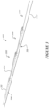
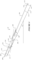
- an angle A s between the surface 219 of the cavity 214 and the base 217 of the foot is less than an angle of incline A i of the inclined building surface 112 (with respect to the horizon), so that water drains from the cavity 214 towards a front 215 of the module.
- the bases 217 of the plurality of feet 206 are coterminous on a plane, so that they all contact the building surface 112 to support the module.
- An angle A s between the surface 219 of the cavity 214 and the plane coterminous with the bases 217 of the feet is less than the angle of incline A i of the inclined building surface.
- an angle A s between the surface 219 of the cavity and the building surface 112 is less than the angle of incline A i of the inclined building surface.
- the angle A s described above is less than 30 degrees, or less than 25 degrees, or less than 20 degrees, or less than 15degrees, or is 10 degrees to 15degrees.
- an angle A s of less than 15degrees allows for a minimum roof angle of incline A i of 15degrees to allow water to drain from the cavity.
- the angle A s is about 11 degrees.
- an angle A, of a surface 223 of the cavity 214 extending between the base 218 of the cavity 214 and a rear 222 ( Fig. 2C ) of the cavity is greater than the angle As of the surface 219 of the cavity extending between the base 218 of the cavity and the front 221 ( Fig. 2C ) of the cavity.
- an angle between the surface 223 of the cavity extending between the base 218 of the cavity and the rear 222 of the cavity and the surface 219 extending between the base 218 of the cavity and the front 221 of the cavity is less than 120 degrees.
- the cavity 214 reduces in width towards a front of the cavity, so that the cavity funnels water towards the front 221 of the cavity.
- the cavity reduces in width between the base 218 of the cavity 214 and the front 221 of the cavity.
- the cavity is approximately teardrop shaped in plan view, a top 221 of the teardrop shape forming the front 221 of the cavity 214.
- the module 200 may be adapted for use in a system to generate electrical energy from solar power. Such products are generally referred to as building integrated photovoltaic products ("BIPV"). A series or array of photovoltaic cells may be carried on the exposed region 204 of the module 200 so that they capture photons when installed on a building surface 112.
- BIPV building integrated photovoltaic products
- a series or array of photovoltaic cells may be carried on the exposed region 204 of the module 200 so that they capture photons when installed on a building surface 112.
- an energy generating module may comprise one or more moulded material layers, a solar array layer of connected photovoltaic cells, and an optional transparent surface laminate layer.
- the energy generating module may also comprise bonding/encapsulation/tie layers to the front and/or back of the PV layer and may also contain layers to stop the corrosion of the PV layer e.g. polyethylene, EFTE, etc.
- the photovoltaic cells installed on a module may be arranged in a row and connected via two bus strips extending the entire length of the module; one running across the upper edges of the cells and one running across the lower edges so that only a single electrical junction for each module need be connected to a main power take-off on installation.
- a further option is to have a bus strip material integrally moulded into the module during the forming process.
- the modules may be molded to accommodate various components of the photovoltaic system.
- the upper surface of the underlapping region may include channels 224 configured to receive cables or wires of the photovoltaic array.
- the upper surface of the underlapping region may also include formed cavities configured to receive junction boxes, printed circuit boards (PCB), communication devices, cables, wires, buses, components, cells, or diodes, and the like of the photovoltaic array.
- the modules may contain all of the hardware and software required to connect and regulate the PV cells.
- Example thermal energy recovery modules and modules comprising an array of solar cells for electrical energy generation, and methods for the continuous forming process for manufacturing such modules are described in WO2013/081477 .
Landscapes
- Engineering & Computer Science (AREA)
- Architecture (AREA)
- Civil Engineering (AREA)
- Structural Engineering (AREA)
- Mechanical Engineering (AREA)
- Sustainable Energy (AREA)
- Life Sciences & Earth Sciences (AREA)
- Sustainable Development (AREA)
- Physics & Mathematics (AREA)
- Thermal Sciences (AREA)
- Chemical & Material Sciences (AREA)
- Combustion & Propulsion (AREA)
- General Engineering & Computer Science (AREA)
- Roof Covering Using Slabs Or Stiff Sheets (AREA)
- Finishing Walls (AREA)
- Building Environments (AREA)
Claims (17)
- Ein Bedachungs-, Fassaden- oder Verkleidungsmodul (200, 300), umfassend:eine unterlappende Region (202), die angepasst ist, um von einer exponierten Region (204) eines angrenzenden überlappenden Moduls im Wesentlichen abgedeckt zu sein, wenn es auf einer geneigten Gebäudefläche (112) montiert ist,eine Vielzahl von Vorsprüngen (206), die auf einer Unterseite der unterlappenden Region gebildet sind, wobei die Vorsprünge:(i) Füße sind, um das Modul auf der geneigten Gebäudefläche(112) zu stützen, um einen Spalt (108) zwischen dem Modul (200, 300) und der geneigten Gebäudefläche bereitzustellen, und/oder(ii) ein Profil auf der Unterseite der unterlappenden Region (202) bereitstellen, um einen Pfad (108) für Luftströmung zwischen dem Modul (200, 300) und der geneigten Gebäudefläche (112) zu definieren,wobei jeder Vorsprung (206) durch einen abwärts vorspringenden Abschnitt der unterlappenden Region (202) mit einem entsprechenden Hohlraum (214) in einer oberen Seite (213) der unterlappenden Region gebildet ist,wobei der Hohlraum (214) geformt ist, um Wasserlachen im Hohlraum zu verhindern oder zu minimieren,wobei eine Fläche (223) des Hohlraums (214), die sich zwischen einer Basis (218) des Hohlraums und einer Vorderseite (221) des Hohlraums erstreckt, geneigt ist, um zu erlauben,dass Wasser aus dem Hohlraum strömt, wenn das Modul auf einer geneigten Gebäudefläche liegt, undwobei mit dem Modul (200, 300) auf der geneigten Gebäudefläche (112) liegend ein Winkel zwischen der Fläche des Hohlraums (214) und der geneigten Gebäudefläche kleiner als ein Neigungswinkel der geneigten Gebäudefläche ist,wobei das Modul (200, 300) mindestens zwei Reihen der genannten Vorsprünge (206) umfasst und wobei die Reihen zwischen einer Vorderseite und Rückseite der unterlappenden Region (202) versetzt oder gestaffelt sind.
- Modul (200, 300) gemäß Anspruch 1, wobei jeder Vorsprung (206) ein genannter Fuß ist und ein Winkel zwischen der Fläche (223) des Hohlraums (214) und einer Basis des Fußes kleiner als der Neigungswinkel der geneigten Gebäudefläche (112) ist.
- Modul (200, 300) gemäß Anspruch 1 oder Anspruch 2, wobei jeder Vorsprung (206) ein genannter Fuß ist und ein Winkel zwischen der Fläche des Hohlraums und einer Ebene deckungsgleich mit Basen der Füße kleiner als der Neigungswinkel der geneigten Gebäudefläche (112) ist.
- Modul (200, 300) gemäß einem der vorhergehenden Ansprüche, wobei der Winkel der Fläche des Hohlraums (214) kleiner als 30 Grad, oder kleiner als 25 Grad, oder kleiner als 20 Grad, oder kleiner als 15 Grad ist oder 10 Grad bis 15 Grad ist.
- Modul (200, 300) gemäß einem der vorhergehenden Ansprüche, wobei ein Winkel einer Fläche des Hohlraums (214), die sich zwischen der Basis des Hohlraums und einer Rückseite des Hohlraums erstreckt, größer als der Winkel der Fläche des Hohlraums ist, die sich zwischen der Basis des Hohlraums und der Vorderseite des Hohlraums erstreckt.
- Modul (200, 300) gemäß Anspruch 7, wobei ein Winkel zwischen der Fläche des Hohlraums (214), die sich zwischen der Basis des Hohlraums und der Rückseite des Hohlraums erstreckt, und der Fläche (223), die sich zwischen der Basis (218) des Hohlraums und der Vorderseite (221) des Hohlraums erstreckt, kleiner als 120 Grad ist.
- Modul (200, 300) gemäß einem der vorhergehenden Ansprüche, wobei der Winkel oder die Winkel auf eine Vorderseite-zu-Rückseite-Mittellinie des Hohlraums (214) bezogen ist oder sind.
- Modul (200, 300) gemäß einem der vorhergehenden Ansprüche, wobei sich der Hohlraum (214) in der Breite zur Vorderseite des Hohlraums hin reduziert, um Wasser zur Vorderseite des Hohlraums hin zu schleusen, wobei sich der Hohlraum optional in der Breite zwischen der Basis des Hohlraums und der Vorderseite des Hohlraums reduziert.
- Modul (200, 300) gemäß einem der vorhergehenden Ansprüche, wobei in Draufsicht der Hohlraum (214) ungefähr tropfenförmig ist, wobei eine Oberseite der Tropfenform die Vorderseite des Hohlraums bildet.
- Modul (200, 300) gemäß einem der vorhergehenden Ansprüche, wobei jeder Vorsprung (206) ein genannter Fuß ist und eine Basis des Fußes einen flachen Abschnitt umfasst, um auf der geneigten Gebäudefläche aufzuliegen, wobei optional eine entsprechende Basis (218) des Hohlraums einen flachen Abschnitt umfasst.
- Modul (200, 300) gemäß einem der vorhergehenden Ansprüche, wobei die Vorsprünge (206) einen gewundenen Pfad für Luftströmung zwischen der geneigten Gebäudefläche (112) und dem Modul erzeugen.
- Modul (200, 300) gemäß einem der vorhergehenden Ansprüche, wobei das Modul ein Startermodul für die Verwendung an einer unteren Kante der geneigten Gebäudefläche ist, wobei das Modul im Wesentlichen von einer exponierten Region (204) eines angrenzenden Bedachungs-, Fassaden- oder Verkleidungsmoduls vollständig überlappt sein wird.
- Modul (200, 300) gemäß einem der vorhergehenden Ansprüche, wobei das Modul eine exponierte Region (204) umfasst, die angepasst ist, um die unterlappende Region (202) eines angrenzenden Moduls abzudecken, wenn es auf der geneigten Gebäudefläche installiert ist, wobei optional eine obere Fläche der exponierten Region eine Photovoltaikzelle oder - vorrichtung umfasst.
- Modul (200, 300) gemäß Anspruch 13, wobei das Modul ferner Folgendes umfasst:einen Vorsprung, der sich von der exponierten Region erstreckt, um eine Auflagefläche bereitzustellen, die der unteren Fläche der exponierten Region zugewandt ist, undein oder mehrere Positionsdetails in der unterlappenden Region, die jeweils der Aufnahme einer Klammer (208) dienen, die eine Zunge (209) umfasst, die angepasst ist, um zwischen der Auflagefläche und der unteren Fläche der exponierten Region eines angrenzenden überlappenden Moduls aufgenommen zu werden, wenn es auf der geneigten Gebäudefläche installiert ist.
- Modul (200, 300) gemäß einem der vorhergehenden Ansprüche, wobei das Modul für die Verwendung als Teil eines Wärmeenergierückgewinnungssystems angepasst ist.
- Eine Bedachungs-, Fassaden- oder Verkleidungseinrichtung, die ein Bedachungs-, Fassaden- oder Verkleidungsmodul (200, 300) gemäß einem der vorhergehenden Ansprüche umfasst, wobei die Einrichtung Folgendes umfasst:
eine oder mehrere Klammern (208), die an der unterlappenden Region (202) befestigt werden können, um eine Zunge (209) bereitzustellen, die angepasst ist, um zwischen einer Auflagefläche und der unteren Fläche einer exponierten Region eines angrenzenden überlappenden Moduls aufgenommen zu werden, wenn es auf der geneigten Gebäudefläche installiert ist. - Ein System (100) zum Abführen oder Rückgewinnen von Wärmeenergie von einer Gebäudefläche, wobei das System Folgendes umfasst:eine Bedachungs-, Fassaden- oder Verkleidungsanordnung, die eine Vielzahl von teilweise überlappenden Modulen (200, 300) umfasst, die im Wesentlichen die Gebäudefläche (112) abdeckt, wobei jedes Modul ein Modul gemäß einem der Ansprüche 1 bis 16 ist; undein Gebläse, das angepasst ist, um die Luftströmung zu induzieren.
Applications Claiming Priority (2)
| Application Number | Priority Date | Filing Date | Title |
|---|---|---|---|
| US201662408986P | 2016-10-17 | 2016-10-17 | |
| PCT/IB2017/056298 WO2018073698A1 (en) | 2016-10-17 | 2017-10-12 | A roofing, cladding or siding module or apparatus |
Publications (3)
| Publication Number | Publication Date |
|---|---|
| EP3526419A1 EP3526419A1 (de) | 2019-08-21 |
| EP3526419A4 EP3526419A4 (de) | 2020-04-15 |
| EP3526419B1 true EP3526419B1 (de) | 2024-08-28 |
Family
ID=62018265
Family Applications (1)
| Application Number | Title | Priority Date | Filing Date |
|---|---|---|---|
| EP17862727.9A Active EP3526419B1 (de) | 2016-10-17 | 2017-10-12 | Dachdeck-, verkleidungs- oder aussenverkleidungsmodul oder vorrichtung |
Country Status (6)
| Country | Link |
|---|---|
| US (1) | US10879842B2 (de) |
| EP (1) | EP3526419B1 (de) |
| JP (1) | JP7046929B2 (de) |
| CN (1) | CN109983188B (de) |
| AU (1) | AU2017345370B2 (de) |
| WO (1) | WO2018073698A1 (de) |
Families Citing this family (1)
| Publication number | Priority date | Publication date | Assignee | Title |
|---|---|---|---|---|
| CN113914555B (zh) * | 2021-10-25 | 2023-05-05 | 重庆聚光新材料科技股份有限公司 | 一种太阳能光伏瓦屋面 |
Family Cites Families (212)
| Publication number | Priority date | Publication date | Assignee | Title |
|---|---|---|---|---|
| US167833A (en) | 1875-09-21 | Improvement in feed mechanisms for file-cutting machines | ||
| DE46673C (de) | G. H. O. BÖKLEN in Stuttgart | Dachplatte mit verschiebbaren Befestigungsklammern | ||
| US510027A (en) | 1893-12-05 | Corn-popper | ||
| US734976A (en) * | 1903-05-21 | 1903-07-28 | Jacob Simmerman | Glass shingle. |
| US1004338A (en) | 1911-08-07 | 1911-09-26 | Nelson A Austin | Molded shingle. |
| US1266137A (en) | 1916-06-26 | 1918-05-14 | Meldetile Corp | Roofing-tile. |
| US1634126A (en) | 1924-12-04 | 1927-06-28 | F L Tyra | Shingle |
| US1678333A (en) | 1926-06-09 | 1928-07-24 | Corroll C Figge | Roof and shingle securing means |
| US1741515A (en) | 1928-08-28 | 1929-12-31 | Halprin Martin | Shingle |
| US1941216A (en) | 1930-10-13 | 1933-12-26 | John C Mckeown | Outside covering for buildings |
| US2149818A (en) | 1937-10-01 | 1939-03-07 | William B North | Building construction |
| US2260446A (en) | 1940-05-24 | 1941-10-28 | Jr Ernest S Fooks | Shingle fastening device |
| US2362236A (en) | 1943-02-13 | 1944-11-07 | Edward F Bassler | Molded shingle |
| US2680565A (en) | 1945-12-03 | 1954-06-08 | Univ Colorado | Solar heating apparatus and method |
| US2568603A (en) | 1948-10-01 | 1951-09-18 | John B Anthony | Roofing and siding |
| US2756699A (en) | 1950-03-31 | 1956-07-31 | Lloyd K Lockwood | Roofing shingles and fasteners |
| US2624298A (en) | 1951-09-04 | 1953-01-06 | Farren Roy | Tile roof structure |
| US2766861A (en) | 1952-06-05 | 1956-10-16 | Abramson Harry | Building wall sidings |
| US3058265A (en) | 1962-03-09 | 1962-10-16 | Lapsensohn Jacob | Roofing shingle and shingle assembly |
| US3332830A (en) | 1963-04-29 | 1967-07-25 | Owens Corning Fiberglass Corp | Asphaltic weathering sheet including continuous glass fibers |
| US3223018A (en) | 1963-11-05 | 1965-12-14 | Tucker Radina | Building structure with air circulation means |
| US3357064A (en) | 1966-02-23 | 1967-12-12 | Bishop & Babcock Corp | Molding clip |
| DE2002738C2 (de) | 1970-01-22 | 1983-11-03 | Manfred 4972 Löhne Mühle | Befestigung von Bekleidungselementen |
| US3661410A (en) | 1970-07-07 | 1972-05-09 | Keystone Consolidated Ind Inc | Panel latching mechanism |
| US4173243A (en) | 1975-10-17 | 1979-11-06 | Dunlop Limited | Safety tire and wheel rim assembly |
| US4173253A (en) | 1977-01-17 | 1979-11-06 | Solar Energy Research Corp. | Solar radiation collector and water cooler |
| US4201196A (en) | 1977-05-11 | 1980-05-06 | Zani David A | Solar energy air heating device |
| US4141182A (en) | 1978-02-02 | 1979-02-27 | Mcmullen John R | Corrosion proof snow guard |
| JPS5849669B2 (ja) | 1978-03-15 | 1983-11-05 | 松下電工株式会社 | 屋根材 |
| US4288959A (en) | 1979-05-21 | 1981-09-15 | Murdock John B | Roofing or siding article |
| US4319437A (en) | 1980-01-24 | 1982-03-16 | Murphy John A | Roofing shingle assembly having solar capabilities |
| US4281639A (en) | 1980-01-31 | 1981-08-04 | Kuronen Seppo K | Solar heating system |
| US4411117A (en) | 1981-05-20 | 1983-10-25 | Bolha David J | Building siding replacement device and method |
| US4426823A (en) | 1981-06-02 | 1984-01-24 | Kobe Thomas R | Apparatus and method for mounting roofing tile |
| DE3320744A1 (de) | 1983-06-09 | 1984-12-13 | Wolfgang Dipl.-Chem. Dr. 6800 Mannheim Blaicher | Dachziegel |
| JPS6193750A (ja) | 1984-10-13 | 1986-05-12 | Fanuc Ltd | フアクトリ−・オ−トメイシヨン・システム |
| JPS61169562A (ja) * | 1985-01-22 | 1986-07-31 | 積水化学工業株式会社 | 屋根 |
| US4956140A (en) | 1985-12-09 | 1990-09-11 | Aluminum Company Of America Alcoa Laboratories | Methods of and apparatus for producing biaxially oriented polymer product |
| JPS6365240A (ja) | 1986-09-05 | 1988-03-23 | Toshiba Corp | 空調装置 |
| GB2199860B (en) * | 1986-11-05 | 1991-07-17 | Glidevale Building Prod | Roof ventilation tile |
| US4712351A (en) | 1986-11-10 | 1987-12-15 | The Celotex Corporation | Vinyl siding |
| US5053180A (en) | 1986-11-24 | 1991-10-01 | Aluminum Company Of America | Process for deformation of amorphous polymers |
| JPS63165633A (ja) | 1986-12-26 | 1988-07-08 | 株式会社オ−エム研究所 | ソ−ラ−システムハウス |
| US5070671A (en) | 1988-01-18 | 1991-12-10 | Oldcastle, Inc. | Roof tiles |
| US5104770A (en) | 1988-03-11 | 1992-04-14 | Hoechst Celanese Corporation | Positive-working photoresist compositions |
| US5094058A (en) | 1988-04-01 | 1992-03-10 | Slocum Donald H | Roofing shingle |
| US4886554A (en) | 1988-09-29 | 1989-12-12 | Gaf Corporation | Solar roofing assembly |
| US5076037A (en) | 1990-03-02 | 1991-12-31 | Nailite International | Decorative wall cover and method of installation |
| US5100274A (en) | 1990-10-29 | 1992-03-31 | Illinois Tool Works Inc. | Roofing fastener and improved screw therefor |
| JP2597243B2 (ja) | 1991-03-18 | 1997-04-02 | 株式会社オーエム研究所 | ソーラーシステムハウスの融雪方法 |
| JPH0534623A (ja) | 1991-07-30 | 1993-02-12 | Canon Inc | 走査光学装置 |
| US5630305A (en) | 1991-08-26 | 1997-05-20 | Hlasnicek; Richard S. | Surface covering unit methods of use and manufacture |
| GB9209397D0 (en) * | 1992-04-30 | 1992-06-17 | Attley Begonia | A fabricated roof tile |
| DE4216171A1 (de) | 1992-05-15 | 1993-01-14 | Walter Loidl | Energieschindel 2 |
| US5347785A (en) | 1992-06-15 | 1994-09-20 | Certainteed Corporation | Two element shingle |
| US5295339A (en) | 1992-08-10 | 1994-03-22 | Manner Value Plastic, Inc. | Simulated individual self-venting overlapping plastic shake |
| JP2940745B2 (ja) | 1992-09-30 | 1999-08-25 | 三洋電機株式会社 | パネル結合装置 |
| JPH083244B2 (ja) | 1993-01-14 | 1996-01-17 | 元旦ビューティ工業株式会社 | 縦葺き屋根構造 |
| US6178703B1 (en) * | 1993-10-05 | 2001-01-30 | Certainteed Corporation | Roofing tile, roof and method of assembling |
| US5437735A (en) | 1993-12-30 | 1995-08-01 | United Solar Systems Corporation | Photovoltaic shingle system |
| JPH07217011A (ja) | 1994-01-26 | 1995-08-15 | Sanso:Kk | 高気密、高断熱住宅の冷暖房システム |
| JPH07218002A (ja) | 1994-01-31 | 1995-08-18 | Yuichi Yanagi | ソーラーシステム及びそれを備えた建物 |
| US5487247A (en) | 1994-06-11 | 1996-01-30 | Pigg; Willard L. | Ventilated roof and wall structure |
| US5475963A (en) | 1994-07-22 | 1995-12-19 | Chelednik; Robert | Method and device for repairing vinyl siding |
| US5690876A (en) | 1994-07-25 | 1997-11-25 | Gallo, Jr.; Francis Anthony | System for continuous production of roofing shakes |
| US5651226A (en) | 1995-02-10 | 1997-07-29 | Archibald; John P. | Tile with solar energy collection capability |
| US5537792A (en) * | 1995-03-23 | 1996-07-23 | Nailite International | Decorative wall covering |
| CN1186532A (zh) | 1995-04-24 | 1998-07-01 | 欧文斯-科尔宁格公司 | 带有加强肋且底面有空腔的瓦 |
| US5615523A (en) | 1995-04-24 | 1997-04-01 | Owens-Corning Fiberglas Technology, Inc. | Roof having resinous shingles |
| JP3440424B2 (ja) | 1995-07-13 | 2003-08-25 | 清水建設株式会社 | 建築物 |
| JP3797685B2 (ja) | 1995-08-25 | 2006-07-19 | ミサワホーム株式会社 | 建物の暖房装置 |
| JP2668665B2 (ja) | 1995-09-06 | 1997-10-27 | 株式会社オーエム研究所 | ソーラーシステムハウス |
| JPH09275644A (ja) | 1996-04-01 | 1997-10-21 | Omron Corp | 太陽電池モジュールおよびそれを用いた太陽光発電システム |
| US5711126A (en) | 1996-05-13 | 1998-01-27 | Owens-Corning Fiberglass Technology, Inc. | Resinous angled shingles for roof ridge lines |
| US5752355A (en) * | 1996-12-12 | 1998-05-19 | Sahramaa; Kimmo J. | Tongue and groove multiple step panel |
| JP3397637B2 (ja) * | 1997-06-11 | 2003-04-21 | キヤノン株式会社 | 太陽電池一体型屋根板、その製造方法、及びその施工方法 |
| WO1998057009A1 (en) | 1997-06-12 | 1998-12-17 | Giuseppe Libralato | Self-ventilating protective and decorative covering for walls and roofs |
| JPH116231A (ja) | 1997-06-17 | 1999-01-12 | Asahi Chem Ind Co Ltd | スラブ構造 |
| US6061978A (en) | 1997-06-25 | 2000-05-16 | Powerlight Corporation | Vented cavity radiant barrier assembly and method |
| US6201179B1 (en) | 1997-10-03 | 2001-03-13 | Nick Dalacu | Array of photovoltaic modules for an integrated solar power collector system |
| JPH11136540A (ja) | 1997-10-27 | 1999-05-21 | Canon Inc | 画像処理装置、コンピュータ読み取り可能な記憶媒体及びデジタル撮影装置 |
| US6164034A (en) | 1998-08-31 | 2000-12-26 | Poly Proximates, Inc. | Fiber-reinforced molded plastic roofing unit and method of making the same |
| AUPP663998A0 (en) | 1998-10-21 | 1998-11-12 | Smith, Lachlan Kerry Oliver | A roof and wall sheeting system |
| GB9827993D0 (en) * | 1998-12-17 | 1999-02-10 | Phi Design Ltd | Ventilated roof tile |
| US6145264A (en) | 1999-02-01 | 2000-11-14 | Dallaire; Michel | Bracket for suspended ceiling tiles |
| GB9913705D0 (en) | 1999-06-14 | 1999-08-11 | Univ Southampton | Solar roofing tile |
| US6248271B1 (en) | 1999-12-16 | 2001-06-19 | Owens Corning Fiberglas Technology, Inc. | Method of making an insert for use in a mold for molding roof covering products |
| US6220956B1 (en) | 2000-02-14 | 2001-04-24 | Jay T. Kilian | Soffit fan |
| CA2301420C (en) | 2000-03-16 | 2008-10-28 | Royal Ecoproducts Ltd. | Plastic roof tiles |
| JP3423917B2 (ja) | 2000-04-18 | 2003-07-07 | 一郎 大本 | 横葺き屋根板装置 |
| US7253076B1 (en) | 2000-06-08 | 2007-08-07 | Micron Technologies, Inc. | Methods for forming and integrated circuit structures containing ruthenium and tungsten containing layers |
| US6908295B2 (en) | 2000-06-16 | 2005-06-21 | Avery Dennison Corporation | Process and apparatus for embossing precise microstructures and embossing tool for making same |
| DE10034655A1 (de) * | 2000-07-16 | 2002-01-24 | Guenter Busch | Vorrichtung zur Nutzung der Sonnenenergie |
| NZ507270A (en) | 2000-09-29 | 2003-04-29 | Andrew Leo Haynes | Flexible tile trim flashings |
| JP2002235955A (ja) | 2001-02-07 | 2002-08-23 | Om Kenkyusho:Kk | ソーラーシステムハウス |
| US6941706B2 (en) | 2001-05-10 | 2005-09-13 | Monier Lifetile Llc | Vented eaves closure |
| NL1018067C2 (nl) | 2001-05-14 | 2002-11-15 | Stichting Energie | Inrichting voor het genereren van fotovoltaïsche energie. |
| JP3654856B2 (ja) | 2001-08-07 | 2005-06-02 | 積水化学工業株式会社 | 太陽電池付き屋根材 |
| US20050072091A1 (en) | 2003-02-14 | 2005-04-07 | Morris Richard Joseph | Roof tile support arrangement |
| WO2003040064A2 (en) | 2001-11-07 | 2003-05-15 | Bioview Ltd. | Kits and methods for preparing cell samples optimized for dual staining |
| US20030096096A1 (en) | 2001-11-19 | 2003-05-22 | Jo Byeong H. | Plastic rail system reinforced with fiberglass thermoplastic composites |
| US20030154667A1 (en) | 2002-02-20 | 2003-08-21 | Dinwoodie Thomas L. | Shingle system |
| JP3652318B2 (ja) | 2002-04-01 | 2005-05-25 | 積水化学工業株式会社 | 太陽電池付き屋根材 |
| US7481057B2 (en) | 2002-04-01 | 2009-01-27 | Niket Keshav Patwardhan | Low cost solar energy extraction |
| US7596919B1 (en) * | 2002-10-18 | 2009-10-06 | Robert Vande Hey | Lightweight composite roofing tiles |
| US8206807B2 (en) | 2003-06-02 | 2012-06-26 | Certainteed Corporation | Synthetic roofing shingle or tile |
| US20050072092A1 (en) * | 2003-10-01 | 2005-04-07 | Scott Williams | High profile composition shingles for roofs |
| US20120117908A1 (en) | 2004-01-14 | 2012-05-17 | Travis Turek | Roofing product |
| US8567601B2 (en) | 2004-01-14 | 2013-10-29 | Tamko Building Products, Inc. | Roofing product |
| US7520098B1 (en) | 2004-01-16 | 2009-04-21 | Davinci Roofscapes, Llc | Stepped tile shingle |
| US7678990B2 (en) | 2004-02-17 | 2010-03-16 | Elk Premium Building Products, Inc. | Flexible integrated photovoltaic roofing membrane and related methods of manufacturing same |
| CA2460236A1 (en) * | 2004-03-08 | 2005-09-08 | Vincenzo Guerra | Construction laminate |
| US7101279B2 (en) | 2004-04-27 | 2006-09-05 | O'hagin Harry T | Solar-powered attic vent with a one-piece, fitted skeleton |
| US7225592B2 (en) | 2004-05-27 | 2007-06-05 | Davis Scott A | Siding clip |
| JP2006022481A (ja) | 2004-07-06 | 2006-01-26 | Mitsubishi Heavy Ind Ltd | ソーラ瓦、ソーラ瓦屋根、およびそれを用いた太陽熱温水設備 |
| US20060026908A1 (en) | 2004-08-05 | 2006-02-09 | Gregori Werner K H | Simulated wood shingles with multiple alignment features |
| US20060080942A1 (en) | 2004-10-15 | 2006-04-20 | O'neill Kevin M | Facing unit construction |
| JP2005191578A (ja) | 2004-11-29 | 2005-07-14 | Takamitsu Hayashida | 太陽光発電システム |
| WO2006063333A2 (en) | 2004-12-09 | 2006-06-15 | University Of Hawaii | Heat and mosture disipating building cladding |
| US7987650B2 (en) | 2008-10-08 | 2011-08-02 | Pollack Robert W | Device and method for repairing building surfaces |
| DE202005002105U1 (de) | 2005-01-05 | 2005-06-30 | Bayerische Dachziegelwerke Bogen Gmbh | Dachziegel |
| US8557366B2 (en) | 2005-08-05 | 2013-10-15 | Owens Corning Intellectual Capital, Llc | Roofing shingle including sheet as headlap |
| US20070078191A1 (en) | 2005-09-30 | 2007-04-05 | Guhde Brian J | Foamed reinforced composite siding product |
| US7441383B2 (en) | 2005-11-04 | 2008-10-28 | O'neal Jerry D | Fastener guide for siding |
| EP1957250B1 (de) | 2005-11-16 | 2018-05-23 | Manufacturing Systems Limited | Verbesserungen einer formvorrichtung oder diese betreffend |
| US20070119109A1 (en) | 2005-11-25 | 2007-05-31 | Peter Kuelker | Precast panel mounting system |
| US20070193620A1 (en) | 2006-01-17 | 2007-08-23 | Hines Braden E | Concentrating solar panel and related systems and methods |
| US7509775B2 (en) | 2006-06-30 | 2009-03-31 | Lumeta, Inc. | Profile roof tile with integrated photovoltaic module |
| US7506477B2 (en) | 2006-06-30 | 2009-03-24 | Lumeta, Inc. | Profile roof tile with integrated photovoltaic module |
| JP4931116B2 (ja) | 2006-07-27 | 2012-05-16 | 日本電信電話株式会社 | 電気化学装置、および電気化学装置のための電極材料の製造方法 |
| US7735287B2 (en) | 2006-10-04 | 2010-06-15 | Novik, Inc. | Roofing panels and roofing system employing the same |
| US20080121270A1 (en) | 2006-11-28 | 2008-05-29 | General Electric Company | Photovoltaic roof tile system |
| NZ577339A (en) | 2006-12-11 | 2012-05-25 | To Ip Holding Company Pty Ltd | Heating and cooling system |
| JP4485539B2 (ja) | 2007-01-23 | 2010-06-23 | オーエム計画株式会社 | ソーラーシステムハウス |
| US7735286B2 (en) | 2007-02-05 | 2010-06-15 | Exteria Building Products | Roof and wall covering with improved corner construction |
| US7726086B2 (en) | 2007-02-05 | 2010-06-01 | Certainteed Corporation | Panel of roofing shingles |
| US20080271773A1 (en) | 2007-05-01 | 2008-11-06 | Jacobs Gregory F | Photovoltaic Devices and Photovoltaic Roofing Elements Including Granules, and Roofs Using Them |
| WO2008137966A2 (en) | 2007-05-07 | 2008-11-13 | Robert Stancel | Structures for low cost, reliable solar roofing |
| US20080302031A1 (en) | 2007-06-05 | 2008-12-11 | Solar Roofing Systems, Inc., | Integrated solar roofing tile connection system |
| CA2691856A1 (en) | 2007-06-25 | 2008-12-31 | Posnansky, Andre | Roof structure for a solar system |
| ITTV20070113A1 (it) | 2007-06-25 | 2008-12-26 | Soleya Srl | Pannello modulare per la copertura ventilata di tetti che integra un modulo intercambiabile a celle fotovoltaiche od uno scambiatore di calore, con moduli collegabili in serie in un sistema combinato di tetto |
| WO2009006213A2 (en) | 2007-06-28 | 2009-01-08 | Kalkanoglu Husnu M | Photovoltaic roofing tiles and methods for making them |
| JP2009127921A (ja) | 2007-11-22 | 2009-06-11 | Om Keikaku Kk | 採冷システム |
| EP2075389B1 (de) | 2007-11-30 | 2012-02-01 | Matthew Barnes | Dachbereich mit solarthermischen Schiefertafeln |
| EP2093807A3 (de) | 2008-02-22 | 2010-03-10 | Redwood Renewables LLC | Niederprofilsperr-PV-Verbindung für ein Solardach |
| US20100037548A1 (en) | 2008-08-18 | 2010-02-18 | Certainteed Corporation | Roofing Product With Zoned Functional Compositions And Methods Of Making The Same |
| US9035499B2 (en) | 2008-09-27 | 2015-05-19 | Witricity Corporation | Wireless energy transfer for photovoltaic panels |
| WO2010036980A1 (en) | 2008-09-27 | 2010-04-01 | Witricity Corporation | Wireless energy transfer systems |
| US8598743B2 (en) | 2008-09-27 | 2013-12-03 | Witricity Corporation | Resonator arrays for wireless energy transfer |
| US8020353B2 (en) | 2008-10-15 | 2011-09-20 | Novik, Inc. | Polymer building products |
| US8468754B2 (en) | 2009-01-08 | 2013-06-25 | Building Materials Investment Corporation | Shingled roof with integrated photovoltaic collectors |
| US8763339B2 (en) | 2009-01-30 | 2014-07-01 | Building Materials Investment Corporation | Energy saving insulated shingle and method of manufacturing same |
| US8333356B2 (en) | 2009-11-02 | 2012-12-18 | Illinois Tool Works Inc. | Wall mountable holder system |
| US8136310B2 (en) | 2009-03-20 | 2012-03-20 | Richard Tweedie | Photovoltaic solar panel mounting system |
| US20100301676A1 (en) | 2009-05-28 | 2010-12-02 | General Electric Company | Solar power generation system including weatherable units including photovoltaic modules and isolated power converters |
| US20100313501A1 (en) | 2009-06-10 | 2010-12-16 | Gangemi Ronald J | Roof mounting bracket for photovoltaic power generation system |
| JP5118102B2 (ja) | 2009-06-25 | 2013-01-16 | 株式会社ニフコ | 押上装置 |
| CN102804550B (zh) | 2009-06-25 | 2014-12-03 | 株式会社村田制作所 | 功率传送系统和非接触充电装置 |
| US20110000535A1 (en) | 2009-07-02 | 2011-01-06 | Sound Solar Solutions Llc | Spanish shingles with photovoltaic cells, method of producing and method of installation |
| WO2011008944A2 (en) | 2009-07-16 | 2011-01-20 | General Cybernation Group, Inc. | Smart and scalable power inverters |
| US8100341B1 (en) | 2009-07-19 | 2012-01-24 | David Roderick | Solar power augmented heat shield systems |
| US8245947B2 (en) * | 2009-07-19 | 2012-08-21 | David Roderick | Thermogenic augmentation system |
| US20110017282A1 (en) | 2009-07-24 | 2011-01-27 | Miasole | Energy transfer through coupling from photovoltaic modules |
| EP2443724B8 (de) | 2009-08-13 | 2013-01-16 | Panasonic Corporation | Drahtlose stromübertragungseinheit sowie stromgenerator und stromerzeugungssystem mit der drahtlosen stromübertragungseinheit |
| US9683703B2 (en) | 2009-08-18 | 2017-06-20 | Charles Edward Matar | Method of storing and transporting light gases |
| US8136322B2 (en) | 2009-08-25 | 2012-03-20 | Tamko Building Products, Inc. | Composite shingle |
| WO2011027627A1 (ja) | 2009-09-01 | 2011-03-10 | シャープ株式会社 | 非接触給電装置用延長コード |
| US8512866B2 (en) | 2009-10-30 | 2013-08-20 | Building Materials Investment Corporation | Flexible solar panel with a multilayer film |
| US8402707B2 (en) | 2010-01-29 | 2013-03-26 | Royal Group Inc. | Interlocking panel system |
| WO2011099109A1 (ja) | 2010-02-15 | 2011-08-18 | 株式会社カナメ | 屋根材付き太陽光発電パネル及び屋根材付き軒先材 |
| DE102010009595A1 (de) | 2010-02-26 | 2011-09-01 | Tilbert Wach | Solarmodul für Gebäudedächer |
| US8387325B2 (en) | 2010-03-08 | 2013-03-05 | Provia Products | Insulated siding apparatus |
| US8215070B2 (en) | 2010-03-19 | 2012-07-10 | Building Materials Investment Corporation | Slate style roofing system with integrated solar panels |
| DE102010019815A1 (de) | 2010-05-10 | 2011-11-10 | Max Amtmann | Photovoltaikanlage |
| KR101179832B1 (ko) | 2010-05-20 | 2012-09-04 | 코오롱글로벌 주식회사 | 태양전지의 열을 이용한 난방장치 |
| US8307599B2 (en) | 2010-07-12 | 2012-11-13 | Certainteed Corporation | Molded shingles with moisture guards for fasteners and with shingle alignment features |
| US20120024283A1 (en) | 2010-07-30 | 2012-02-02 | Skillman Dale N | Hybrid Solar Thermal and Photovoltaic Collector |
| RU2013112820A (ru) * | 2010-09-08 | 2014-10-20 | 3М Инновейтив Пропертиз Компани | Изделие для вентиляции кровли над обрешеткой крыши |
| US8782967B2 (en) | 2010-09-27 | 2014-07-22 | Gregory S. Daniels | Above sheathing ventilation system |
| US9048358B2 (en) | 2010-12-17 | 2015-06-02 | Dow Global Technologies Llc | Photovoltaic device |
| JP2014520220A (ja) * | 2011-06-07 | 2014-08-21 | スリーエム イノベイティブ プロパティズ カンパニー | 屋根の管理用システム及び方法 |
| JP2014531892A (ja) | 2011-09-22 | 2014-11-27 | ダウ グローバル テクノロジーズ エルエルシー | 改良された熱管理機構を有する光起電力デバイス |
| US20140190921A1 (en) | 2011-09-23 | 2014-07-10 | RCO2 Washington, Inc. | Environment friendly building system utilizing recycled/upcycled, collapsed, pre-formed & post consumer plastic material |
| US8245475B1 (en) | 2011-09-23 | 2012-08-21 | Thomson Donald W | Environment friendly building system utilizing recycled/upcycled, collapsed, preformed and post consumer plastic material |
| US9397499B2 (en) | 2011-09-29 | 2016-07-19 | Sunlight Photonics Inc. | Methods and apparatus for high-frequency electrical power collection and transfer |
| US20130095293A1 (en) | 2011-10-14 | 2013-04-18 | Daniel E. Boss | Shingle Coloring System |
| CN104011970A (zh) | 2011-10-18 | 2014-08-27 | WiTricity公司 | 用于光伏板的无线能量传输 |
| HK1200602A1 (en) | 2011-11-04 | 2015-08-07 | WiTricity公司 | Wireless energy transfer modeling tool |
| CA2794345A1 (en) | 2011-11-14 | 2013-05-14 | Certainteed Corporation | Photovoltaic roofing elements and photovoltaic roofing systems |
| WO2013081477A1 (en) | 2011-11-30 | 2013-06-06 | Zinniatek Limited | A roofing, cladding or siding product, its manufacture and its use as part of a solar energy recovery system |
| WO2013081478A1 (en) | 2011-11-30 | 2013-06-06 | Zinniatek Limited | Photovoltaic systems |
| US20130167463A1 (en) | 2012-01-04 | 2013-07-04 | National Applied Construction Products, Inc. | Composite tile product |
| US8994224B2 (en) | 2012-01-27 | 2015-03-31 | Building Materials Investment Corporation | Solar roof shingles and underlayment with wireless power transfer |
| EP2819958A1 (de) * | 2012-02-29 | 2015-01-07 | Corning Incorporated | Glasvakuumisolationstafeln und verfahren |
| US20130255755A1 (en) | 2012-03-30 | 2013-10-03 | Building Materials Investment Corporation | Solar Roof Shingles and Underlayment with Wireless Power Transfer and Related Components and Systems |
| CA2828941C (en) | 2012-10-01 | 2021-04-06 | Building Materials Investment Corporation | Solar panel roof system with raised access panels |
| MX345857B (es) | 2012-10-02 | 2017-02-20 | Building Materials Invest Corp | Sistema de panel solar integrado en techo con microinversores montados a los lados. |
| US8925262B2 (en) | 2013-03-13 | 2015-01-06 | Building Materials Investment Corporation | Multi-purpose ridge vent system |
| US9169646B2 (en) | 2013-03-15 | 2015-10-27 | Building Materials Investment Corporation | Low profile slate-style solar roofing system |
| US9166523B2 (en) | 2013-03-15 | 2015-10-20 | Building Materials Investment Corportion | Low profile solar roof shingle system with integrated nano-inverters |
| US9923515B2 (en) | 2013-03-15 | 2018-03-20 | Building Materials Investment Corporation | Solar panels with contactless panel-to-panel connections |
| WO2014189391A1 (en) | 2013-05-23 | 2014-11-27 | Zinniatek Limited | Photovoltaic systems |
| US9010058B2 (en) | 2013-08-15 | 2015-04-21 | Building Materials Investment Corporation | Shingle with transition device for impact resistance |
| US10502435B2 (en) * | 2013-09-06 | 2019-12-10 | Zinniatek Limited | Solar thermal roofing system |
| WO2015132756A1 (en) | 2014-03-07 | 2015-09-11 | Zinniatek Limited | Solar thermal roofing system |
| US9416540B2 (en) | 2013-11-27 | 2016-08-16 | Tapco International Corporation | Dual-arch roof tile |
| US9322173B2 (en) | 2014-02-05 | 2016-04-26 | Michael Pisani | Lightweight shingle assembly |
| KR20150099466A (ko) | 2014-02-21 | 2015-08-31 | 오웬스 코닝 인텔렉츄얼 캐피탈 엘엘씨 | 증가된 소수성을 갖는 지붕널들 |
| AU2015356689B2 (en) | 2014-12-01 | 2020-10-15 | Zinniatek Limited | A roofing, cladding or siding apparatus |
| HRP20211065T1 (hr) * | 2015-05-26 | 2021-10-15 | Arcelormittal | Ploča, sklop ploče i pridruženi krov |
| JP6427806B2 (ja) | 2015-09-25 | 2018-11-28 | 株式会社三共 | 遊技機 |
| JP6764562B2 (ja) | 2016-06-14 | 2020-10-07 | 株式会社ジェイテクト | ステアリング装置 |
-
2017
- 2017-10-12 WO PCT/IB2017/056298 patent/WO2018073698A1/en not_active Ceased
- 2017-10-12 CN CN201780064018.XA patent/CN109983188B/zh active Active
- 2017-10-12 EP EP17862727.9A patent/EP3526419B1/de active Active
- 2017-10-12 US US16/342,055 patent/US10879842B2/en active Active
- 2017-10-12 JP JP2019518487A patent/JP7046929B2/ja active Active
- 2017-10-12 AU AU2017345370A patent/AU2017345370B2/en active Active
Also Published As
| Publication number | Publication date |
|---|---|
| AU2017345370A1 (en) | 2019-05-02 |
| US20190238090A1 (en) | 2019-08-01 |
| JP7046929B2 (ja) | 2022-04-04 |
| EP3526419A4 (de) | 2020-04-15 |
| US10879842B2 (en) | 2020-12-29 |
| WO2018073698A1 (en) | 2018-04-26 |
| EP3526419A1 (de) | 2019-08-21 |
| CN109983188B (zh) | 2021-11-26 |
| AU2017345370B2 (en) | 2023-08-31 |
| CN109983188A (zh) | 2019-07-05 |
| JP2019532199A (ja) | 2019-11-07 |
| NZ752380A (en) | 2024-12-20 |
Similar Documents
| Publication | Publication Date | Title |
|---|---|---|
| US10858839B2 (en) | Roofing, cladding or siding product, its manufacture and its use as part of a solar energy recovery system | |
| US8215071B2 (en) | Integrated composition shingle PV system | |
| JP6786489B2 (ja) | 屋根、外装またはサイディング用装置 | |
| US9212832B2 (en) | Photovoltaic systems, methods for installing photovoltaic systems, and kits for installing photovoltaic systems | |
| US8701360B2 (en) | Method and apparatus for assembling photovoltaic modules | |
| US11011912B2 (en) | Photovoltaic systems | |
| US8966838B2 (en) | Photovoltaic systems, methods for installing photovoltaic systems, and kits for installing photovoltaic systems | |
| US8707643B1 (en) | Roofing element and roof covering comprised thereof | |
| US10171025B2 (en) | Apparatus and method for solar panel module mounting inserts | |
| EP3526419B1 (de) | Dachdeck-, verkleidungs- oder aussenverkleidungsmodul oder vorrichtung | |
| NZ738483B2 (en) | A roofing, cladding or siding product, its manufacture and its use as part of a solar energy recovery system | |
| NZ722380A (en) | A roofing, cladding or siding product, its manufacture and its use as part of a solar energy recovery system | |
| NZ722380B2 (en) | A roofing, cladding or siding product, its manufacture and its use as part of a solar energy recovery system |
Legal Events
| Date | Code | Title | Description |
|---|---|---|---|
| STAA | Information on the status of an ep patent application or granted ep patent |
Free format text: STATUS: THE INTERNATIONAL PUBLICATION HAS BEEN MADE |
|
| PUAI | Public reference made under article 153(3) epc to a published international application that has entered the european phase |
Free format text: ORIGINAL CODE: 0009012 |
|
| STAA | Information on the status of an ep patent application or granted ep patent |
Free format text: STATUS: REQUEST FOR EXAMINATION WAS MADE |
|
| 17P | Request for examination filed |
Effective date: 20190401 |
|
| AK | Designated contracting states |
Kind code of ref document: A1 Designated state(s): AL AT BE BG CH CY CZ DE DK EE ES FI FR GB GR HR HU IE IS IT LI LT LU LV MC MK MT NL NO PL PT RO RS SE SI SK SM TR |
|
| AX | Request for extension of the european patent |
Extension state: BA ME |
|
| DAV | Request for validation of the european patent (deleted) | ||
| DAX | Request for extension of the european patent (deleted) | ||
| A4 | Supplementary search report drawn up and despatched |
Effective date: 20200318 |
|
| RIC1 | Information provided on ipc code assigned before grant |
Ipc: F24S 20/67 20180101ALI20200312BHEP Ipc: E04D 13/17 20060101ALI20200312BHEP Ipc: E04D 1/30 20060101AFI20200312BHEP Ipc: E04D 3/18 20060101ALI20200312BHEP Ipc: E04F 13/00 20060101ALI20200312BHEP Ipc: E04D 1/12 20060101ALI20200312BHEP Ipc: E04F 13/18 20060101ALI20200312BHEP Ipc: E04F 13/08 20060101ALI20200312BHEP Ipc: F24S 10/50 20180101ALI20200312BHEP Ipc: E04D 3/365 20060101ALI20200312BHEP Ipc: E04D 1/26 20060101ALI20200312BHEP Ipc: E04D 3/02 20060101ALI20200312BHEP |
|
| STAA | Information on the status of an ep patent application or granted ep patent |
Free format text: STATUS: EXAMINATION IS IN PROGRESS |
|
| 17Q | First examination report despatched |
Effective date: 20220209 |
|
| GRAP | Despatch of communication of intention to grant a patent |
Free format text: ORIGINAL CODE: EPIDOSNIGR1 |
|
| STAA | Information on the status of an ep patent application or granted ep patent |
Free format text: STATUS: GRANT OF PATENT IS INTENDED |
|
| INTG | Intention to grant announced |
Effective date: 20240320 |
|
| P01 | Opt-out of the competence of the unified patent court (upc) registered |
Free format text: CASE NUMBER: APP_33319/2024 Effective date: 20240604 |
|
| GRAS | Grant fee paid |
Free format text: ORIGINAL CODE: EPIDOSNIGR3 |
|
| GRAA | (expected) grant |
Free format text: ORIGINAL CODE: 0009210 |
|
| STAA | Information on the status of an ep patent application or granted ep patent |
Free format text: STATUS: THE PATENT HAS BEEN GRANTED |
|
| AK | Designated contracting states |
Kind code of ref document: B1 Designated state(s): AL AT BE BG CH CY CZ DE DK EE ES FI FR GB GR HR HU IE IS IT LI LT LU LV MC MK MT NL NO PL PT RO RS SE SI SK SM TR |
|
| REG | Reference to a national code |
Ref country code: GB Ref legal event code: FG4D |
|
| REG | Reference to a national code |
Ref country code: CH Ref legal event code: EP |
|
| REG | Reference to a national code |
Ref country code: DE Ref legal event code: R096 Ref document number: 602017084531 Country of ref document: DE |
|
| RAP4 | Party data changed (patent owner data changed or rights of a patent transferred) |
Owner name: ZINNIATEK LIMITED |
|
| REG | Reference to a national code |
Ref country code: IE Ref legal event code: FG4D |
|
| REG | Reference to a national code |
Ref country code: LT Ref legal event code: MG9D |
|
| PG25 | Lapsed in a contracting state [announced via postgrant information from national office to epo] |
Ref country code: NO Free format text: LAPSE BECAUSE OF FAILURE TO SUBMIT A TRANSLATION OF THE DESCRIPTION OR TO PAY THE FEE WITHIN THE PRESCRIBED TIME-LIMIT Effective date: 20241128 |
|
| REG | Reference to a national code |
Ref country code: AT Ref legal event code: MK05 Ref document number: 1718088 Country of ref document: AT Kind code of ref document: T Effective date: 20240828 |
|
| PG25 | Lapsed in a contracting state [announced via postgrant information from national office to epo] |
Ref country code: NL Free format text: LAPSE BECAUSE OF FAILURE TO SUBMIT A TRANSLATION OF THE DESCRIPTION OR TO PAY THE FEE WITHIN THE PRESCRIBED TIME-LIMIT Effective date: 20240828 Ref country code: GR Free format text: LAPSE BECAUSE OF FAILURE TO SUBMIT A TRANSLATION OF THE DESCRIPTION OR TO PAY THE FEE WITHIN THE PRESCRIBED TIME-LIMIT Effective date: 20241129 Ref country code: PT Free format text: LAPSE BECAUSE OF FAILURE TO SUBMIT A TRANSLATION OF THE DESCRIPTION OR TO PAY THE FEE WITHIN THE PRESCRIBED TIME-LIMIT Effective date: 20241230 Ref country code: PL Free format text: LAPSE BECAUSE OF FAILURE TO SUBMIT A TRANSLATION OF THE DESCRIPTION OR TO PAY THE FEE WITHIN THE PRESCRIBED TIME-LIMIT Effective date: 20240828 Ref country code: FI Free format text: LAPSE BECAUSE OF FAILURE TO SUBMIT A TRANSLATION OF THE DESCRIPTION OR TO PAY THE FEE WITHIN THE PRESCRIBED TIME-LIMIT Effective date: 20240828 |
|
| PG25 | Lapsed in a contracting state [announced via postgrant information from national office to epo] |
Ref country code: BG Free format text: LAPSE BECAUSE OF FAILURE TO SUBMIT A TRANSLATION OF THE DESCRIPTION OR TO PAY THE FEE WITHIN THE PRESCRIBED TIME-LIMIT Effective date: 20240828 |
|
| PG25 | Lapsed in a contracting state [announced via postgrant information from national office to epo] |
Ref country code: LV Free format text: LAPSE BECAUSE OF FAILURE TO SUBMIT A TRANSLATION OF THE DESCRIPTION OR TO PAY THE FEE WITHIN THE PRESCRIBED TIME-LIMIT Effective date: 20240828 |
|
| REG | Reference to a national code |
Ref country code: NL Ref legal event code: MP Effective date: 20240828 |
|
| PG25 | Lapsed in a contracting state [announced via postgrant information from national office to epo] |
Ref country code: AT Free format text: LAPSE BECAUSE OF FAILURE TO SUBMIT A TRANSLATION OF THE DESCRIPTION OR TO PAY THE FEE WITHIN THE PRESCRIBED TIME-LIMIT Effective date: 20240828 Ref country code: IS Free format text: LAPSE BECAUSE OF FAILURE TO SUBMIT A TRANSLATION OF THE DESCRIPTION OR TO PAY THE FEE WITHIN THE PRESCRIBED TIME-LIMIT Effective date: 20241228 |
|
| PG25 | Lapsed in a contracting state [announced via postgrant information from national office to epo] |
Ref country code: HR Free format text: LAPSE BECAUSE OF FAILURE TO SUBMIT A TRANSLATION OF THE DESCRIPTION OR TO PAY THE FEE WITHIN THE PRESCRIBED TIME-LIMIT Effective date: 20240828 |
|
| PG25 | Lapsed in a contracting state [announced via postgrant information from national office to epo] |
Ref country code: ES Free format text: LAPSE BECAUSE OF FAILURE TO SUBMIT A TRANSLATION OF THE DESCRIPTION OR TO PAY THE FEE WITHIN THE PRESCRIBED TIME-LIMIT Effective date: 20240828 Ref country code: RS Free format text: LAPSE BECAUSE OF FAILURE TO SUBMIT A TRANSLATION OF THE DESCRIPTION OR TO PAY THE FEE WITHIN THE PRESCRIBED TIME-LIMIT Effective date: 20241128 |
|
| PG25 | Lapsed in a contracting state [announced via postgrant information from national office to epo] |
Ref country code: RS Free format text: LAPSE BECAUSE OF FAILURE TO SUBMIT A TRANSLATION OF THE DESCRIPTION OR TO PAY THE FEE WITHIN THE PRESCRIBED TIME-LIMIT Effective date: 20241128 Ref country code: PT Free format text: LAPSE BECAUSE OF FAILURE TO SUBMIT A TRANSLATION OF THE DESCRIPTION OR TO PAY THE FEE WITHIN THE PRESCRIBED TIME-LIMIT Effective date: 20241230 Ref country code: PL Free format text: LAPSE BECAUSE OF FAILURE TO SUBMIT A TRANSLATION OF THE DESCRIPTION OR TO PAY THE FEE WITHIN THE PRESCRIBED TIME-LIMIT Effective date: 20240828 Ref country code: NO Free format text: LAPSE BECAUSE OF FAILURE TO SUBMIT A TRANSLATION OF THE DESCRIPTION OR TO PAY THE FEE WITHIN THE PRESCRIBED TIME-LIMIT Effective date: 20241128 Ref country code: NL Free format text: LAPSE BECAUSE OF FAILURE TO SUBMIT A TRANSLATION OF THE DESCRIPTION OR TO PAY THE FEE WITHIN THE PRESCRIBED TIME-LIMIT Effective date: 20240828 Ref country code: LV Free format text: LAPSE BECAUSE OF FAILURE TO SUBMIT A TRANSLATION OF THE DESCRIPTION OR TO PAY THE FEE WITHIN THE PRESCRIBED TIME-LIMIT Effective date: 20240828 Ref country code: IS Free format text: LAPSE BECAUSE OF FAILURE TO SUBMIT A TRANSLATION OF THE DESCRIPTION OR TO PAY THE FEE WITHIN THE PRESCRIBED TIME-LIMIT Effective date: 20241228 Ref country code: HR Free format text: LAPSE BECAUSE OF FAILURE TO SUBMIT A TRANSLATION OF THE DESCRIPTION OR TO PAY THE FEE WITHIN THE PRESCRIBED TIME-LIMIT Effective date: 20240828 Ref country code: GR Free format text: LAPSE BECAUSE OF FAILURE TO SUBMIT A TRANSLATION OF THE DESCRIPTION OR TO PAY THE FEE WITHIN THE PRESCRIBED TIME-LIMIT Effective date: 20241129 Ref country code: FI Free format text: LAPSE BECAUSE OF FAILURE TO SUBMIT A TRANSLATION OF THE DESCRIPTION OR TO PAY THE FEE WITHIN THE PRESCRIBED TIME-LIMIT Effective date: 20240828 Ref country code: ES Free format text: LAPSE BECAUSE OF FAILURE TO SUBMIT A TRANSLATION OF THE DESCRIPTION OR TO PAY THE FEE WITHIN THE PRESCRIBED TIME-LIMIT Effective date: 20240828 Ref country code: BG Free format text: LAPSE BECAUSE OF FAILURE TO SUBMIT A TRANSLATION OF THE DESCRIPTION OR TO PAY THE FEE WITHIN THE PRESCRIBED TIME-LIMIT Effective date: 20240828 Ref country code: AT Free format text: LAPSE BECAUSE OF FAILURE TO SUBMIT A TRANSLATION OF THE DESCRIPTION OR TO PAY THE FEE WITHIN THE PRESCRIBED TIME-LIMIT Effective date: 20240828 |
|
| PG25 | Lapsed in a contracting state [announced via postgrant information from national office to epo] |
Ref country code: RO Free format text: LAPSE BECAUSE OF FAILURE TO SUBMIT A TRANSLATION OF THE DESCRIPTION OR TO PAY THE FEE WITHIN THE PRESCRIBED TIME-LIMIT Effective date: 20240828 Ref country code: SM Free format text: LAPSE BECAUSE OF FAILURE TO SUBMIT A TRANSLATION OF THE DESCRIPTION OR TO PAY THE FEE WITHIN THE PRESCRIBED TIME-LIMIT Effective date: 20240828 Ref country code: DK Free format text: LAPSE BECAUSE OF FAILURE TO SUBMIT A TRANSLATION OF THE DESCRIPTION OR TO PAY THE FEE WITHIN THE PRESCRIBED TIME-LIMIT Effective date: 20240828 |
|
| PG25 | Lapsed in a contracting state [announced via postgrant information from national office to epo] |
Ref country code: EE Free format text: LAPSE BECAUSE OF FAILURE TO SUBMIT A TRANSLATION OF THE DESCRIPTION OR TO PAY THE FEE WITHIN THE PRESCRIBED TIME-LIMIT Effective date: 20240828 |
|
| PG25 | Lapsed in a contracting state [announced via postgrant information from national office to epo] |
Ref country code: CZ Free format text: LAPSE BECAUSE OF FAILURE TO SUBMIT A TRANSLATION OF THE DESCRIPTION OR TO PAY THE FEE WITHIN THE PRESCRIBED TIME-LIMIT Effective date: 20240828 |
|
| PG25 | Lapsed in a contracting state [announced via postgrant information from national office to epo] |
Ref country code: IT Free format text: LAPSE BECAUSE OF FAILURE TO SUBMIT A TRANSLATION OF THE DESCRIPTION OR TO PAY THE FEE WITHIN THE PRESCRIBED TIME-LIMIT Effective date: 20240828 Ref country code: SK Free format text: LAPSE BECAUSE OF FAILURE TO SUBMIT A TRANSLATION OF THE DESCRIPTION OR TO PAY THE FEE WITHIN THE PRESCRIBED TIME-LIMIT Effective date: 20240828 |
|
| REG | Reference to a national code |
Ref country code: CH Ref legal event code: PL Ref country code: DE Ref legal event code: R097 Ref document number: 602017084531 Country of ref document: DE |
|
| PLBE | No opposition filed within time limit |
Free format text: ORIGINAL CODE: 0009261 |
|
| STAA | Information on the status of an ep patent application or granted ep patent |
Free format text: STATUS: NO OPPOSITION FILED WITHIN TIME LIMIT |
|
| PG25 | Lapsed in a contracting state [announced via postgrant information from national office to epo] |
Ref country code: MC Free format text: LAPSE BECAUSE OF FAILURE TO SUBMIT A TRANSLATION OF THE DESCRIPTION OR TO PAY THE FEE WITHIN THE PRESCRIBED TIME-LIMIT Effective date: 20240828 |
|
| PG25 | Lapsed in a contracting state [announced via postgrant information from national office to epo] |
Ref country code: LU Free format text: LAPSE BECAUSE OF NON-PAYMENT OF DUE FEES Effective date: 20241012 Ref country code: BE Free format text: LAPSE BECAUSE OF NON-PAYMENT OF DUE FEES Effective date: 20241031 |
|
| PG25 | Lapsed in a contracting state [announced via postgrant information from national office to epo] |
Ref country code: CH Free format text: LAPSE BECAUSE OF NON-PAYMENT OF DUE FEES Effective date: 20241031 |
|
| 26N | No opposition filed |
Effective date: 20250530 |
|
| REG | Reference to a national code |
Ref country code: BE Ref legal event code: MM Effective date: 20241031 |
|
| PG25 | Lapsed in a contracting state [announced via postgrant information from national office to epo] |
Ref country code: SE Free format text: LAPSE BECAUSE OF FAILURE TO SUBMIT A TRANSLATION OF THE DESCRIPTION OR TO PAY THE FEE WITHIN THE PRESCRIBED TIME-LIMIT Effective date: 20240828 |
|
| PG25 | Lapsed in a contracting state [announced via postgrant information from national office to epo] |
Ref country code: IE Free format text: LAPSE BECAUSE OF NON-PAYMENT OF DUE FEES Effective date: 20241012 |
|
| PGFP | Annual fee paid to national office [announced via postgrant information from national office to epo] |
Ref country code: DE Payment date: 20251029 Year of fee payment: 9 |
|
| PGFP | Annual fee paid to national office [announced via postgrant information from national office to epo] |
Ref country code: GB Payment date: 20251023 Year of fee payment: 9 |
|
| PGFP | Annual fee paid to national office [announced via postgrant information from national office to epo] |
Ref country code: FR Payment date: 20251114 Year of fee payment: 9 |
|
| PG25 | Lapsed in a contracting state [announced via postgrant information from national office to epo] |
Ref country code: CY Free format text: LAPSE BECAUSE OF FAILURE TO SUBMIT A TRANSLATION OF THE DESCRIPTION OR TO PAY THE FEE WITHIN THE PRESCRIBED TIME-LIMIT; INVALID AB INITIO Effective date: 20171012 |
|
| PG25 | Lapsed in a contracting state [announced via postgrant information from national office to epo] |
Ref country code: HU Free format text: LAPSE BECAUSE OF FAILURE TO SUBMIT A TRANSLATION OF THE DESCRIPTION OR TO PAY THE FEE WITHIN THE PRESCRIBED TIME-LIMIT; INVALID AB INITIO Effective date: 20171012 |