EP3499785A1 - Netzwerkarchitektur, verfahren und vorrichtungen für ein drahtloskommunikationsnetzwerk - Google Patents
Netzwerkarchitektur, verfahren und vorrichtungen für ein drahtloskommunikationsnetzwerk Download PDFInfo
- Publication number
- EP3499785A1 EP3499785A1 EP18210345.7A EP18210345A EP3499785A1 EP 3499785 A1 EP3499785 A1 EP 3499785A1 EP 18210345 A EP18210345 A EP 18210345A EP 3499785 A1 EP3499785 A1 EP 3499785A1
- Authority
- EP
- European Patent Office
- Prior art keywords
- wireless device
- user data
- rrc
- lte
- numerology
- Prior art date
- Legal status (The legal status is an assumption and is not a legal conclusion. Google has not performed a legal analysis and makes no representation as to the accuracy of the status listed.)
- Granted
Links
- 238000000034 method Methods 0.000 title claims abstract description 772
- 238000004891 communication Methods 0.000 title claims abstract description 261
- 230000005540 biological transmission Effects 0.000 claims abstract description 861
- 230000004044 response Effects 0.000 claims abstract description 97
- 238000012545 processing Methods 0.000 claims description 429
- 230000008569 process Effects 0.000 claims description 167
- 230000000977 initiatory effect Effects 0.000 claims description 5
- 238000005259 measurement Methods 0.000 description 217
- 230000011664 signaling Effects 0.000 description 160
- 238000013461 design Methods 0.000 description 154
- 108700026140 MAC combination Proteins 0.000 description 134
- 230000006870 function Effects 0.000 description 102
- 230000010354 integration Effects 0.000 description 95
- 230000008901 benefit Effects 0.000 description 90
- 238000001228 spectrum Methods 0.000 description 83
- 230000007246 mechanism Effects 0.000 description 80
- 210000004027 cell Anatomy 0.000 description 69
- 238000013459 approach Methods 0.000 description 61
- 230000009977 dual effect Effects 0.000 description 52
- 241000700159 Rattus Species 0.000 description 51
- 238000005516 engineering process Methods 0.000 description 51
- 238000007726 management method Methods 0.000 description 49
- 238000001514 detection method Methods 0.000 description 46
- 230000002776 aggregation Effects 0.000 description 44
- 238000004220 aggregation Methods 0.000 description 44
- 230000000875 corresponding effect Effects 0.000 description 41
- 238000010586 diagram Methods 0.000 description 41
- 239000013256 coordination polymer Substances 0.000 description 40
- 125000004122 cyclic group Chemical group 0.000 description 40
- 230000008093 supporting effect Effects 0.000 description 39
- 241000854291 Dianthus carthusianorum Species 0.000 description 36
- 230000007704 transition Effects 0.000 description 35
- 230000001427 coherent effect Effects 0.000 description 34
- 206010009944 Colon cancer Diseases 0.000 description 31
- 241000169170 Boreogadus saida Species 0.000 description 29
- 230000006399 behavior Effects 0.000 description 29
- 239000000872 buffer Substances 0.000 description 29
- 230000008859 change Effects 0.000 description 27
- 230000001965 increasing effect Effects 0.000 description 27
- 230000002829 reductive effect Effects 0.000 description 27
- 230000001960 triggered effect Effects 0.000 description 26
- 238000009826 distribution Methods 0.000 description 25
- 238000013507 mapping Methods 0.000 description 25
- 238000012544 monitoring process Methods 0.000 description 25
- 230000001360 synchronised effect Effects 0.000 description 25
- 238000003491 array Methods 0.000 description 24
- 238000013468 resource allocation Methods 0.000 description 24
- 238000001530 Raman microscopy Methods 0.000 description 23
- 238000003860 storage Methods 0.000 description 22
- 238000012384 transportation and delivery Methods 0.000 description 22
- 238000005192 partition Methods 0.000 description 21
- 238000002156 mixing Methods 0.000 description 20
- 238000005457 optimization Methods 0.000 description 20
- 230000001413 cellular effect Effects 0.000 description 19
- 235000008694 Humulus lupulus Nutrition 0.000 description 18
- 230000007420 reactivation Effects 0.000 description 18
- 238000001914 filtration Methods 0.000 description 17
- 238000013439 planning Methods 0.000 description 17
- 230000003595 spectral effect Effects 0.000 description 17
- 230000006978 adaptation Effects 0.000 description 15
- 230000000694 effects Effects 0.000 description 15
- 238000000638 solvent extraction Methods 0.000 description 15
- 101001018494 Homo sapiens Pro-MCH Proteins 0.000 description 14
- 102100033721 Pro-MCH Human genes 0.000 description 14
- 230000004913 activation Effects 0.000 description 14
- 230000009286 beneficial effect Effects 0.000 description 14
- 238000005265 energy consumption Methods 0.000 description 14
- 238000005562 fading Methods 0.000 description 13
- 230000000737 periodic effect Effects 0.000 description 13
- 230000003068 static effect Effects 0.000 description 13
- 239000013598 vector Substances 0.000 description 13
- 230000001976 improved effect Effects 0.000 description 12
- 230000002452 interceptive effect Effects 0.000 description 12
- 230000007774 longterm Effects 0.000 description 12
- 238000011144 upstream manufacturing Methods 0.000 description 12
- 239000000969 carrier Substances 0.000 description 11
- 230000001934 delay Effects 0.000 description 11
- 230000008450 motivation Effects 0.000 description 11
- 230000036961 partial effect Effects 0.000 description 11
- 230000000295 complement effect Effects 0.000 description 10
- 230000000670 limiting effect Effects 0.000 description 10
- 230000011218 segmentation Effects 0.000 description 10
- 238000012546 transfer Methods 0.000 description 10
- 238000010168 coupling process Methods 0.000 description 9
- 238000005859 coupling reaction Methods 0.000 description 9
- 230000001788 irregular Effects 0.000 description 9
- 239000000203 mixture Substances 0.000 description 9
- 230000009467 reduction Effects 0.000 description 9
- 238000010408 sweeping Methods 0.000 description 9
- 230000008878 coupling Effects 0.000 description 8
- 230000007423 decrease Effects 0.000 description 8
- 230000001419 dependent effect Effects 0.000 description 8
- 230000002349 favourable effect Effects 0.000 description 8
- 230000002779 inactivation Effects 0.000 description 8
- 239000011159 matrix material Substances 0.000 description 8
- 238000007781 pre-processing Methods 0.000 description 8
- 230000009471 action Effects 0.000 description 7
- 238000004458 analytical method Methods 0.000 description 7
- 230000015556 catabolic process Effects 0.000 description 7
- 238000011109 contamination Methods 0.000 description 7
- 238000006731 degradation reaction Methods 0.000 description 7
- 238000012913 prioritisation Methods 0.000 description 7
- 101001055444 Homo sapiens Mediator of RNA polymerase II transcription subunit 20 Proteins 0.000 description 6
- 102100026165 Mediator of RNA polymerase II transcription subunit 20 Human genes 0.000 description 6
- 108091005487 SCARB1 Proteins 0.000 description 6
- 102100037118 Scavenger receptor class B member 1 Human genes 0.000 description 6
- 238000009825 accumulation Methods 0.000 description 6
- 230000003466 anti-cipated effect Effects 0.000 description 6
- 210000001520 comb Anatomy 0.000 description 6
- 238000011161 development Methods 0.000 description 6
- 230000018109 developmental process Effects 0.000 description 6
- 238000011156 evaluation Methods 0.000 description 6
- 230000012010 growth Effects 0.000 description 6
- 230000003993 interaction Effects 0.000 description 6
- 238000002955 isolation Methods 0.000 description 6
- 230000004048 modification Effects 0.000 description 6
- 238000012986 modification Methods 0.000 description 6
- 230000010287 polarization Effects 0.000 description 6
- 238000011084 recovery Methods 0.000 description 6
- 238000000926 separation method Methods 0.000 description 6
- 238000003892 spreading Methods 0.000 description 6
- 238000012360 testing method Methods 0.000 description 6
- 208000005229 Autosomal recessive Robinow syndrome Diseases 0.000 description 5
- 101100264657 Enterobacteria phage T4 y12D gene Proteins 0.000 description 5
- 102100029454 T cell receptor alpha chain MC.7.G5 Human genes 0.000 description 5
- 238000007792 addition Methods 0.000 description 5
- 230000003139 buffering effect Effects 0.000 description 5
- 230000001276 controlling effect Effects 0.000 description 5
- 230000008713 feedback mechanism Effects 0.000 description 5
- 230000006872 improvement Effects 0.000 description 5
- 230000005855 radiation Effects 0.000 description 5
- 238000001945 resonance Rayleigh scattering spectroscopy Methods 0.000 description 5
- 230000008054 signal transmission Effects 0.000 description 5
- 101100150275 Caenorhabditis elegans srb-3 gene Proteins 0.000 description 4
- 108010076504 Protein Sorting Signals Proteins 0.000 description 4
- 230000003213 activating effect Effects 0.000 description 4
- 238000013475 authorization Methods 0.000 description 4
- 230000006835 compression Effects 0.000 description 4
- 238000007906 compression Methods 0.000 description 4
- 238000004590 computer program Methods 0.000 description 4
- 238000000794 confocal Raman spectroscopy Methods 0.000 description 4
- 238000012937 correction Methods 0.000 description 4
- 238000011500 cytoreductive surgery Methods 0.000 description 4
- 230000004069 differentiation Effects 0.000 description 4
- 239000000835 fiber Substances 0.000 description 4
- 238000012423 maintenance Methods 0.000 description 4
- 230000002085 persistent effect Effects 0.000 description 4
- 230000002441 reversible effect Effects 0.000 description 4
- 208000000649 small cell carcinoma Diseases 0.000 description 4
- 230000008685 targeting Effects 0.000 description 4
- 101150096310 SIB1 gene Proteins 0.000 description 3
- 238000010276 construction Methods 0.000 description 3
- 230000006735 deficit Effects 0.000 description 3
- 230000003111 delayed effect Effects 0.000 description 3
- 238000000280 densification Methods 0.000 description 3
- 238000009434 installation Methods 0.000 description 3
- 230000033001 locomotion Effects 0.000 description 3
- 238000004519 manufacturing process Methods 0.000 description 3
- 230000035515 penetration Effects 0.000 description 3
- 238000002360 preparation method Methods 0.000 description 3
- 238000004088 simulation Methods 0.000 description 3
- 230000007480 spreading Effects 0.000 description 3
- 230000002311 subsequent effect Effects 0.000 description 3
- 238000012549 training Methods 0.000 description 3
- 238000013519 translation Methods 0.000 description 3
- KVCQTKNUUQOELD-UHFFFAOYSA-N 4-amino-n-[1-(3-chloro-2-fluoroanilino)-6-methylisoquinolin-5-yl]thieno[3,2-d]pyrimidine-7-carboxamide Chemical compound N=1C=CC2=C(NC(=O)C=3C4=NC=NC(N)=C4SC=3)C(C)=CC=C2C=1NC1=CC=CC(Cl)=C1F KVCQTKNUUQOELD-UHFFFAOYSA-N 0.000 description 2
- 241000196324 Embryophyta Species 0.000 description 2
- 101100264654 Enterobacteria phage T4 y12A gene Proteins 0.000 description 2
- 230000033228 biological regulation Effects 0.000 description 2
- 238000004364 calculation method Methods 0.000 description 2
- 230000010267 cellular communication Effects 0.000 description 2
- 238000006243 chemical reaction Methods 0.000 description 2
- 230000019771 cognition Effects 0.000 description 2
- 230000002596 correlated effect Effects 0.000 description 2
- 230000006866 deterioration Effects 0.000 description 2
- 230000005611 electricity Effects 0.000 description 2
- 238000009432 framing Methods 0.000 description 2
- 238000003306 harvesting Methods 0.000 description 2
- 230000035876 healing Effects 0.000 description 2
- 208000018910 keratinopathic ichthyosis Diseases 0.000 description 2
- 238000011068 loading method Methods 0.000 description 2
- 230000000116 mitigating effect Effects 0.000 description 2
- 239000013307 optical fiber Substances 0.000 description 2
- 238000011176 pooling Methods 0.000 description 2
- 230000001105 regulatory effect Effects 0.000 description 2
- 230000002040 relaxant effect Effects 0.000 description 2
- 230000008439 repair process Effects 0.000 description 2
- 238000012772 sequence design Methods 0.000 description 2
- 230000004617 sleep duration Effects 0.000 description 2
- 230000001629 suppression Effects 0.000 description 2
- 238000001356 surgical procedure Methods 0.000 description 2
- 230000009466 transformation Effects 0.000 description 2
- 230000002618 waking effect Effects 0.000 description 2
- 239000002699 waste material Substances 0.000 description 2
- VCGRFBXVSFAGGA-UHFFFAOYSA-N (1,1-dioxo-1,4-thiazinan-4-yl)-[6-[[3-(4-fluorophenyl)-5-methyl-1,2-oxazol-4-yl]methoxy]pyridin-3-yl]methanone Chemical compound CC=1ON=C(C=2C=CC(F)=CC=2)C=1COC(N=C1)=CC=C1C(=O)N1CCS(=O)(=O)CC1 VCGRFBXVSFAGGA-UHFFFAOYSA-N 0.000 description 1
- BYHQTRFJOGIQAO-GOSISDBHSA-N 3-(4-bromophenyl)-8-[(2R)-2-hydroxypropyl]-1-[(3-methoxyphenyl)methyl]-1,3,8-triazaspiro[4.5]decan-2-one Chemical compound C[C@H](CN1CCC2(CC1)CN(C(=O)N2CC3=CC(=CC=C3)OC)C4=CC=C(C=C4)Br)O BYHQTRFJOGIQAO-GOSISDBHSA-N 0.000 description 1
- CYJRNFFLTBEQSQ-UHFFFAOYSA-N 8-(3-methyl-1-benzothiophen-5-yl)-N-(4-methylsulfonylpyridin-3-yl)quinoxalin-6-amine Chemical compound CS(=O)(=O)C1=C(C=NC=C1)NC=1C=C2N=CC=NC2=C(C=1)C=1C=CC2=C(C(=CS2)C)C=1 CYJRNFFLTBEQSQ-UHFFFAOYSA-N 0.000 description 1
- 101100494773 Caenorhabditis elegans ctl-2 gene Proteins 0.000 description 1
- 241000283153 Cetacea Species 0.000 description 1
- 102100039201 Constitutive coactivator of peroxisome proliferator-activated receptor gamma Human genes 0.000 description 1
- 206010011878 Deafness Diseases 0.000 description 1
- 208000037170 Delayed Emergence from Anesthesia Diseases 0.000 description 1
- MWRWFPQBGSZWNV-UHFFFAOYSA-N Dinitrosopentamethylenetetramine Chemical compound C1N2CN(N=O)CN1CN(N=O)C2 MWRWFPQBGSZWNV-UHFFFAOYSA-N 0.000 description 1
- 101001022742 Drosophila melanogaster Unconventional myosin IC Proteins 0.000 description 1
- 241000760358 Enodes Species 0.000 description 1
- 101100264655 Enterobacteria phage T4 y12B gene Proteins 0.000 description 1
- 101100112369 Fasciola hepatica Cat-1 gene Proteins 0.000 description 1
- 102100022887 GTP-binding nuclear protein Ran Human genes 0.000 description 1
- 241000282412 Homo Species 0.000 description 1
- 101000813317 Homo sapiens Constitutive coactivator of peroxisome proliferator-activated receptor gamma Proteins 0.000 description 1
- 101000973503 Homo sapiens E3 ubiquitin-protein ligase MIB1 Proteins 0.000 description 1
- 101000998783 Homo sapiens Insulin-like 3 Proteins 0.000 description 1
- 101100005271 Neurospora crassa (strain ATCC 24698 / 74-OR23-1A / CBS 708.71 / DSM 1257 / FGSC 987) cat-1 gene Proteins 0.000 description 1
- 102100032835 Oligoribonuclease, mitochondrial Human genes 0.000 description 1
- 101150039363 SIB2 gene Proteins 0.000 description 1
- 102100036407 Thioredoxin Human genes 0.000 description 1
- 230000004931 aggregating effect Effects 0.000 description 1
- 230000032683 aging Effects 0.000 description 1
- 238000004873 anchoring Methods 0.000 description 1
- 230000002457 bidirectional effect Effects 0.000 description 1
- 230000015572 biosynthetic process Effects 0.000 description 1
- 210000004271 bone marrow stromal cell Anatomy 0.000 description 1
- 229940112112 capex Drugs 0.000 description 1
- 150000001875 compounds Chemical class 0.000 description 1
- 239000012141 concentrate Substances 0.000 description 1
- 238000012790 confirmation Methods 0.000 description 1
- 239000013078 crystal Substances 0.000 description 1
- 230000001186 cumulative effect Effects 0.000 description 1
- 238000013500 data storage Methods 0.000 description 1
- 230000009849 deactivation Effects 0.000 description 1
- 231100000895 deafness Toxicity 0.000 description 1
- 238000000354 decomposition reaction Methods 0.000 description 1
- 230000006837 decompression Effects 0.000 description 1
- 230000003247 decreasing effect Effects 0.000 description 1
- 230000007850 degeneration Effects 0.000 description 1
- 238000009795 derivation Methods 0.000 description 1
- 230000003467 diminishing effect Effects 0.000 description 1
- 230000009365 direct transmission Effects 0.000 description 1
- 230000002708 enhancing effect Effects 0.000 description 1
- 239000000796 flavoring agent Substances 0.000 description 1
- 235000019634 flavors Nutrition 0.000 description 1
- 238000009472 formulation Methods 0.000 description 1
- 230000008014 freezing Effects 0.000 description 1
- 238000007710 freezing Methods 0.000 description 1
- 208000016354 hearing loss disease Diseases 0.000 description 1
- 238000011835 investigation Methods 0.000 description 1
- 230000009191 jumping Effects 0.000 description 1
- 238000010801 machine learning Methods 0.000 description 1
- 230000005012 migration Effects 0.000 description 1
- 238000013508 migration Methods 0.000 description 1
- 238000010295 mobile communication Methods 0.000 description 1
- 230000008520 organization Effects 0.000 description 1
- 230000008447 perception Effects 0.000 description 1
- 238000012805 post-processing Methods 0.000 description 1
- 230000002028 premature Effects 0.000 description 1
- 238000004801 process automation Methods 0.000 description 1
- 230000000644 propagated effect Effects 0.000 description 1
- 230000001902 propagating effect Effects 0.000 description 1
- 238000013442 quality metrics Methods 0.000 description 1
- 238000013139 quantization Methods 0.000 description 1
- 230000003362 replicative effect Effects 0.000 description 1
- 238000011160 research Methods 0.000 description 1
- 238000005070 sampling Methods 0.000 description 1
- 238000010187 selection method Methods 0.000 description 1
- 230000001953 sensory effect Effects 0.000 description 1
- 238000007493 shaping process Methods 0.000 description 1
- 238000004904 shortening Methods 0.000 description 1
- XGVXKJKTISMIOW-ZDUSSCGKSA-N simurosertib Chemical compound N1N=CC(C=2SC=3C(=O)NC(=NC=3C=2)[C@H]2N3CCC(CC3)C2)=C1C XGVXKJKTISMIOW-ZDUSSCGKSA-N 0.000 description 1
- 239000007787 solid Substances 0.000 description 1
- 238000012358 sourcing Methods 0.000 description 1
- 229920003048 styrene butadiene rubber Polymers 0.000 description 1
- 230000002459 sustained effect Effects 0.000 description 1
- 230000002195 synergetic effect Effects 0.000 description 1
- 230000009897 systematic effect Effects 0.000 description 1
- CSRZQMIRAZTJOY-UHFFFAOYSA-N trimethylsilyl iodide Substances C[Si](C)(C)I CSRZQMIRAZTJOY-UHFFFAOYSA-N 0.000 description 1
- 238000010200 validation analysis Methods 0.000 description 1
- 230000000007 visual effect Effects 0.000 description 1
Images


Classifications
-
- H—ELECTRICITY
- H04—ELECTRIC COMMUNICATION TECHNIQUE
- H04J—MULTIPLEX COMMUNICATION
- H04J11/00—Orthogonal multiplex systems, e.g. using WALSH codes
- H04J11/0069—Cell search, i.e. determining cell identity [cell-ID]
- H04J11/0079—Acquisition of downlink reference signals, e.g. detection of cell-ID
-
- H—ELECTRICITY
- H04—ELECTRIC COMMUNICATION TECHNIQUE
- H04B—TRANSMISSION
- H04B7/00—Radio transmission systems, i.e. using radiation field
- H04B7/02—Diversity systems; Multi-antenna system, i.e. transmission or reception using multiple antennas
- H04B7/04—Diversity systems; Multi-antenna system, i.e. transmission or reception using multiple antennas using two or more spaced independent antennas
- H04B7/0413—MIMO systems
- H04B7/0452—Multi-user MIMO systems
-
- H—ELECTRICITY
- H04—ELECTRIC COMMUNICATION TECHNIQUE
- H04B—TRANSMISSION
- H04B7/00—Radio transmission systems, i.e. using radiation field
- H04B7/02—Diversity systems; Multi-antenna system, i.e. transmission or reception using multiple antennas
- H04B7/04—Diversity systems; Multi-antenna system, i.e. transmission or reception using multiple antennas using two or more spaced independent antennas
- H04B7/08—Diversity systems; Multi-antenna system, i.e. transmission or reception using multiple antennas using two or more spaced independent antennas at the receiving station
- H04B7/0837—Diversity systems; Multi-antenna system, i.e. transmission or reception using multiple antennas using two or more spaced independent antennas at the receiving station using pre-detection combining
- H04B7/0842—Weighted combining
- H04B7/0848—Joint weighting
-
- H—ELECTRICITY
- H04—ELECTRIC COMMUNICATION TECHNIQUE
- H04L—TRANSMISSION OF DIGITAL INFORMATION, e.g. TELEGRAPHIC COMMUNICATION
- H04L5/00—Arrangements affording multiple use of the transmission path
- H04L5/003—Arrangements for allocating sub-channels of the transmission path
- H04L5/0053—Allocation of signaling, i.e. of overhead other than pilot signals
-
- H—ELECTRICITY
- H04—ELECTRIC COMMUNICATION TECHNIQUE
- H04L—TRANSMISSION OF DIGITAL INFORMATION, e.g. TELEGRAPHIC COMMUNICATION
- H04L5/00—Arrangements affording multiple use of the transmission path
- H04L5/14—Two-way operation using the same type of signal, i.e. duplex
- H04L5/1469—Two-way operation using the same type of signal, i.e. duplex using time-sharing
-
- H—ELECTRICITY
- H04—ELECTRIC COMMUNICATION TECHNIQUE
- H04L—TRANSMISSION OF DIGITAL INFORMATION, e.g. TELEGRAPHIC COMMUNICATION
- H04L65/00—Network arrangements, protocols or services for supporting real-time applications in data packet communication
- H04L65/10—Architectures or entities
- H04L65/102—Gateways
- H04L65/1023—Media gateways
-
- H—ELECTRICITY
- H04—ELECTRIC COMMUNICATION TECHNIQUE
- H04W—WIRELESS COMMUNICATION NETWORKS
- H04W4/00—Services specially adapted for wireless communication networks; Facilities therefor
-
- H—ELECTRICITY
- H04—ELECTRIC COMMUNICATION TECHNIQUE
- H04W—WIRELESS COMMUNICATION NETWORKS
- H04W8/00—Network data management
- H04W8/18—Processing of user or subscriber data, e.g. subscribed services, user preferences or user profiles; Transfer of user or subscriber data
-
- H—ELECTRICITY
- H04—ELECTRIC COMMUNICATION TECHNIQUE
- H04L—TRANSMISSION OF DIGITAL INFORMATION, e.g. TELEGRAPHIC COMMUNICATION
- H04L5/00—Arrangements affording multiple use of the transmission path
- H04L5/0001—Arrangements for dividing the transmission path
- H04L5/0003—Two-dimensional division
- H04L5/0005—Time-frequency
- H04L5/0007—Time-frequency the frequencies being orthogonal, e.g. OFDM(A), DMT
-
- H—ELECTRICITY
- H04—ELECTRIC COMMUNICATION TECHNIQUE
- H04L—TRANSMISSION OF DIGITAL INFORMATION, e.g. TELEGRAPHIC COMMUNICATION
- H04L5/00—Arrangements affording multiple use of the transmission path
- H04L5/0001—Arrangements for dividing the transmission path
- H04L5/0028—Variable division
-
- H—ELECTRICITY
- H04—ELECTRIC COMMUNICATION TECHNIQUE
- H04L—TRANSMISSION OF DIGITAL INFORMATION, e.g. TELEGRAPHIC COMMUNICATION
- H04L5/00—Arrangements affording multiple use of the transmission path
- H04L5/0091—Signaling for the administration of the divided path
-
- H—ELECTRICITY
- H04—ELECTRIC COMMUNICATION TECHNIQUE
- H04W—WIRELESS COMMUNICATION NETWORKS
- H04W48/00—Access restriction; Network selection; Access point selection
- H04W48/08—Access restriction or access information delivery, e.g. discovery data delivery
- H04W48/12—Access restriction or access information delivery, e.g. discovery data delivery using downlink control channel
-
- H—ELECTRICITY
- H04—ELECTRIC COMMUNICATION TECHNIQUE
- H04W—WIRELESS COMMUNICATION NETWORKS
- H04W48/00—Access restriction; Network selection; Access point selection
- H04W48/16—Discovering, processing access restriction or access information
-
- H—ELECTRICITY
- H04—ELECTRIC COMMUNICATION TECHNIQUE
- H04W—WIRELESS COMMUNICATION NETWORKS
- H04W60/00—Affiliation to network, e.g. registration; Terminating affiliation with the network, e.g. de-registration
- H04W60/04—Affiliation to network, e.g. registration; Terminating affiliation with the network, e.g. de-registration using triggered events
-
- H—ELECTRICITY
- H04—ELECTRIC COMMUNICATION TECHNIQUE
- H04W—WIRELESS COMMUNICATION NETWORKS
- H04W72/00—Local resource management
- H04W72/12—Wireless traffic scheduling
-
- H—ELECTRICITY
- H04—ELECTRIC COMMUNICATION TECHNIQUE
- H04W—WIRELESS COMMUNICATION NETWORKS
- H04W74/00—Wireless channel access, e.g. scheduled or random access
- H04W74/02—Hybrid access techniques
-
- H—ELECTRICITY
- H04—ELECTRIC COMMUNICATION TECHNIQUE
- H04W—WIRELESS COMMUNICATION NETWORKS
- H04W74/00—Wireless channel access, e.g. scheduled or random access
- H04W74/08—Non-scheduled or contention based access, e.g. random access, ALOHA, CSMA [Carrier Sense Multiple Access]
- H04W74/0808—Non-scheduled or contention based access, e.g. random access, ALOHA, CSMA [Carrier Sense Multiple Access] using carrier sensing, e.g. as in CSMA
- H04W74/0816—Non-scheduled or contention based access, e.g. random access, ALOHA, CSMA [Carrier Sense Multiple Access] using carrier sensing, e.g. as in CSMA carrier sensing with collision avoidance
-
- H—ELECTRICITY
- H04—ELECTRIC COMMUNICATION TECHNIQUE
- H04W—WIRELESS COMMUNICATION NETWORKS
- H04W74/00—Wireless channel access, e.g. scheduled or random access
- H04W74/08—Non-scheduled or contention based access, e.g. random access, ALOHA, CSMA [Carrier Sense Multiple Access]
- H04W74/0833—Non-scheduled or contention based access, e.g. random access, ALOHA, CSMA [Carrier Sense Multiple Access] using a random access procedure
-
- H—ELECTRICITY
- H04—ELECTRIC COMMUNICATION TECHNIQUE
- H04W—WIRELESS COMMUNICATION NETWORKS
- H04W8/00—Network data management
- H04W8/22—Processing or transfer of terminal data, e.g. status or physical capabilities
- H04W8/24—Transfer of terminal data
-
- H—ELECTRICITY
- H04—ELECTRIC COMMUNICATION TECHNIQUE
- H04W—WIRELESS COMMUNICATION NETWORKS
- H04W80/00—Wireless network protocols or protocol adaptations to wireless operation
- H04W80/02—Data link layer protocols
Definitions
- the present disclosure is related to wireless communications networks and describes network architecture, wireless devices, and wireless network nodes suitable for, but not limited to, a fifth-generation (5G) wireless communications network.
- 5G fifth-generation
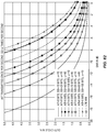
- New spectrum for 5G is expected to be available after 2020.
- the actual frequency bands, and the amount of spectrum, have not yet been identified.
- the identification of frequency bands above 6 GHz for mobile telecommunications will be handled in the World Radio Conference in 2019 (WRC-19).
- New frequency bands below 6 GHz for mobile telecommunications are handled in WRC-15.
- all mobile telecommunications bands, from below 1 GHz, up to as high as 100 GHz, could potentially become candidates for 5G.
- it is expected that the first commercial deployment of 5G will happen in frequency bands close to 4 GHz, and that 28 GHz deployments will come later.
- the International Telecommunication Union has outlined a vision for 5G, which it will refer to as "IMT-2020," providing a first glimpse of potential scenarios, use cases and related ITU requirements that eventually will define 5G.
- XP051079528 (3GPP R1-162228 "Frame structure design of new RAT") addresses issues related to the frame structure design including how to multiplex different kinds of TTIs, basic principles for TTI design and considerations on support of wireless backhaul.
- XPP051080002 (3GPP R1-162156 "Scenario and design criteria on flexible numerologies") contains a discussion regarding scenarios and design criteria for flexible OFDM numerologies to support diverse services and diverse deployments for 5G New Radio.
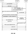
- Embodiments of the various techniques, devices, and systems disclosed herein include wireless devices such as user equipment (UE) and methods carried out by such devices.
- An example of such a method includes receiving a downlink signal comprising an uplink access configuration index, using the uplink access configuration index to identify an uplink access configuration from among a predetermined plurality of uplink access configurations, and transmitting to the wireless communications network according to the identified uplink access configuration.
- the method also includes receiving, in a first downlink subframe, a first OFDM transmission formatted according to a first numerology and receiving, in a second downlink subframe, a second OFDM transmission formatted according to a second numerology, the second numerology differing from the first numerology.
- the first numerology has a first subcarrier spacing and the second numerology has a second subcarrier spacing, where the first subcarrier spacing differs from the second subcarrier spacing.
- the method may furthermore comprise receiving broadcasted system access information and using the received system access information for accessing the wireless communications network.
- the first OFDM transmission may have a numerology according to the 3GPP specifications for LTE, for example.
- the first and second downlink subframes may be received on the same carrier frequency.
- the first and second numerologies may comprise subframes of first and second subframe lengths, respectively, where the first subframe length differs from the second subframe length.
- the subframes of the first and second numerologies may comprise first and second predetermined numbers of OFDM symbols, respectively.
- At least one of the first and second numerologies may comprise subframes having a length of 250 microseconds or less.
- the method may furthermore comprise requesting additional system information from the wireless communications network and receiving additional system information from the wireless communications network, in response to the requesting.
- the method may further comprise receiving additional system information from the wireless communications network, in a dedicated transmission.
- the first OFDM transmission may be frequency-multiplexed with and at least partly overlapping in time with the second OFDM transmission.
- the method may further comprise receiving, in a first-in-time OFDM symbol of the first or second downlink subframe, downlink control signalling in a first set of subcarriers of the first-in-time OFDM symbol and dedicated user data in a second set of subcarriers of the first-in-time OFDM symbol.
- the method may further comprise transmitting acknowledgement (ACK) or negative acknowledgement (NACK) data in response to the first OFDM transmission in the first downlink subframe, in a last OFDM symbol of an uplink subframe interval at least partially overlapping the first downlink subframe.
- ACK acknowledgement
- NACK negative acknowledgement
- the first downlink subframe may comprise one or more reference symbols in the first-in-time OFDM symbol of the first downlink subframe, and the method may also comprise beginning decoding of the first OFDM transmission in the first downlink subframe before a duration of the first downlink subframe has ended, using a channel estimate based on the one or more reference symbols.
- the method may further comprise receiving information defining the plurality of uplink access configurations, on a first carrier, where the downlink signal comprising the uplink access configuration index may be received on a second carrier, differing from said first carrier.
- the method may further comprise receiving a third OFDM transmission formatted according to the first numerology, the third OFDM transmission occupying a transmission time interval (TTI) having a length equal to a plurality of subframes according to the first numerology.
- TTI transmission time interval
- At least one of the first and second OFDM transmissions may be a Discrete Fourier Transform-Spread OFDM (DFTS-OFDM) transmission.
- DFTS-OFDM Discrete Fourier Transform-Spread OFDM
- the method may further include receiving and processing first Layer 2 data on a first physical data channel and receiving and processing second Layer 2 data on a second physical data channel.
- the receiving and processing of the first Layer 2 data comprises the use of soft HARQ combining, and the receiving and processing of the second Layer 2 data comprises no soft HARQ combining.
- This may include using a common set of demodulation reference signals for receiving both the first and second Layer 2 data.
- the common set of demodulation reference signals may be a user-specific set of demodulation reference signals.
- the method may further comprise receiving a physical control channel using a set of demodulation reference signals that differs from the common set of demodulation reference signals.
- a single RRC approach may be used.
- the method in a wireless device may further include processing data from the first OFDM transmission using a first MAC protocol layer and processing data from the second OFDM transmission using a second MAC protocol layer, where the first MAC protocol layer differs from the second MAC protocol layer.
- the method may further include processing messages received from each of the first and second MAC protocol layers using a single, common RRC protocol layer.
- the method in the wireless device further includes processing data from the first OFDM transmission using a first MAC protocol layer and processing data from the second OFDM transmission using a second MAC protocol layer, where the first MAC protocol layer differs from the second MAC protocol layer.
- the method may further include processing messages received via the first MAC protocol layer using a first RRC protocol layer and processing messages received via the second MAC protocol layer using a second RRC protocol layer, where the first RRC protocol layer differs from the second RRC protocol layer.
- At least a first one of the first and second RRC protocol layers is configured to pass selected RRC messages to the other one of the first and second RRC protocol layers.
- the selected RRC messages are RRC messages received and processed by the first one of the first and second RRC protocol layers but targeted for the other one of the first and second RRC protocol layers.
- the method in the wireless device may further include transmitting third Layer 2 data on a third physical data channel and transmitting fourth Layer 2 data on a fourth physical data channel.
- the transmitting of the third Layer 2 data comprises the use of a HARQ process supporting soft combining, and the transmitting of the fourth Layer 2 data comprises no HARQ process.
- the method includes operating in a connected mode for one or more first intervals and operating in a dormant mode for one or more second intervals, where the first and second OFDM transmissions are performed in the connected mode.
- Operating in the dormant mode comprises monitoring signals carrying tracking area identifiers, comparing tracking area identifiers received during the monitoring with a tracking area identifier list, and notifying the wireless communication network in response to determining that a received tracking area identifier is not on the list but otherwise refraining from notifying the wireless communication network in response to receiving changing tracking area identifiers.
- the method in the wireless device may include transmitting, to the wireless communications network, a capability pointer, the capability pointer identifying a set of capabilities, for the wireless device, stored in the wireless communications network.
- the set of capabilities may include at least one of wireless device vendor (e.g. a UE vendor), capability version, or proprietary information of the wireless device (e.g. proprietary UE information) or of the network.
- the method may comprise transmitting to the wireless communications network using Discrete Fourier Transform-Spread OFDM (DFTS-OFDM) transmission.
- DFTS-OFDM Discrete Fourier Transform-Spread OFDM
- the method may include transmitting to the wireless communications network using a contention-based access protocol.
- the contention-based access protocol may comprise a listen-before-talk (LBT) access mechanism.
- the transmitting to the wireless communications network using the contention-based access protocol may comprise transmitting a message that indicates an identity of a Hybrid Automatic Repeat Request (HARQ) buffer associated with the message.
- the transmitting to the wireless communications network using the contention-based access protocol may be responsive to first receiving a clear-to-send signal.
- the transmitting to the wireless communications network using the contention-based access protocol may be responsive to receiving a message granting uplink resources for transmitting according to the contention-based access protocol.
- the transmitting to the wireless communications network using the contention-based access protocol may comprise transmitting a message that indicates an identity of the wireless device, e.g. the UE identity.
- the transmitting to the wireless communications network using the contention-based access protocol may comprise transmitting using a contention-based resource that is pre-scheduled for potential usage.
- the method in the wireless device may further include measuring a first mobility reference signal on a first received beam and measuring a second mobility reference signal on a second received beam, where the second mobility reference signal differs from the first mobility reference signal.
- the method may further include reporting results of measuring the first and second mobility reference signals to the wireless communications network.
- the first mobility reference signal may comprise the concatenation of a first time and frequency synchronization signal (TSS) and a first beam reference signal (BRS) in time into one OFDM symbol.
- the concatenation of the first time and frequency synchronization signal (TSS) and the first beam reference signal (BRS) in time into one OFDM symbol may be done according to a discrete Fourier Transform (DFT) precoding.
- the method may also include receiving, in response to reporting the results, a command to switch from receiving data on a current downlink beam to receiving data on a different downlink beam.
- the method may include receiving a timing advance value for application to the different downlink beam.
- the receiving of at least one of the first and second OFDM transmissions may comprise decoding the at least one of said first and second OFDM transmissions using a polar code.
- the receiving of at least one of the first and second OFDM transmissions may comprise decoding the at least one of the first and second OFDM transmissions using a low-density parity check (LDPC) code.
- LDPC low-density parity check
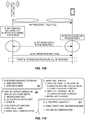
- An example of such a method includes transmitting a first downlink signal comprising an uplink access configuration index, the uplink access configuration index identifying an uplink access configuration from among a plurality of predetermined uplink access configurations, and subsequently receiving a transmission from a first wireless device, e.g. a UE, according to the identified uplink access configuration.
- the method also includes transmitting, in a first downlink subframe, a first OFDM transmission formatted according to a first numerology and transmitting, in a second downlink subframe, a second OFDM transmission formatted according to a second numerology, the second numerology differing from the first numerology.
- the first numerology has a first subcarrier spacing and the second numerology has a second subcarrier spacing, where the first subcarrier spacing differs from the second subcarrier spacing.
- the first and second downlink subframes may be transmitted on the same carrier frequency.
- the transmitting of the first downlink signal is performed by a first instance of radio network equipment, while the transmitting of the first and second OFDM transmissions is performed by a second instance of radio network equipment.
- the first OFDM transmission may have a numerology according to the specifications for LTE, for example.
- the first and second numerologies may comprise subframes of first and second subframe lengths, respectively, where the first subframe length differs from the second subframe length.
- the subframes of the first and second numerologies may comprise first and second predetermined numbers of OFDM symbols, respectively.
- At least one of the first and second numerologies may comprise subframes having a length of 250 microseconds or less.
- the first OFDM transmission may be frequency-multiplexed with and at least partly overlapping in time with the second OFDM transmission.
- the method may further comprise transmitting, in a first-in-time OFDM symbol of the first or second downlink subframe, downlink control signalling in first subcarriers of the First-in-time OFDM symbol and dedicated user data in second subcarriers of said First-in-time OFDM symbol.
- the method may further comprise receiving acknowledgement (ACK) or negative acknowledgement (NACK) data in response to the first OFDM transmission in the first downlink subframe, in a last OFDM symbol of an uplink subframe interval at least partially overlapping the first downlink subframe.
- ACK acknowledgement
- NACK negative acknowledgement
- the method may further comprise transmitting a third OFDM transmission formatted according to the first numerology, the third OFDM transmission occupying a transmission time interval (TTI) having a length equal to a plurality of subframes according to the first numerology.
- TTI transmission time interval
- At least one of the first and second OFDM transmissions may be a Discrete Fourier Transform-Spread OFDM (DFTS-OFDM) transmission.
- DFTS-OFDM Discrete Fourier Transform-Spread OFDM
- the method carried out by radio network equipment may include transmitting a second downlink signal comprising an access information signal, the access information signal indicating a plurality of uplink access configurations, where the uplink access configuration index identifies one of the plurality of uplink access configurations.
- the transmitting of the second downlink signal may be performed by a third instance of radio network equipment.
- the method in the radio network equipment includes processing and transmitting first Layer 2 data on a first physical data channel and processing and transmitting second Layer 2 data on a second physical data channel.
- the processing and transmitting of the first Layer 2 data comprises the use of a HARQ process supporting soft combining, and the processing and transmitting of the second Layer 2 data comprises no HARQ process.
- the transmitting of the first and second Layer 2 data may be performed using a common antenna port, where the method further includes transmitting a common set of demodulation reference signals, using the common antenna port, for use in receiving both the first and second Layer 2 data.
- the common set of demodulation reference signals are for use by wireless devices in receiving both the first and second Layer 2 data.
- the common set of demodulation reference signals may be a user-specific set of demodulation reference signals.
- the method may further comprise transmitting a physical control channel using a set of demodulation reference signals that differs from the common set of demodulation reference signals.
- the method in the radio network equipment may include receiving and processing third Layer 2 data on a third physical data channel and receiving and processing fourth Layer 2 data on a fourth physical data channel, where the receiving and processing of the third Layer 2 data comprises the use of soft HARQ combining and the receiving and processing of the fourth Layer 2 data comprises no soft HARQ combining.
- the transmitting of the first and second OFDM transmissions may be performed by one instance of the radio network equipment, where the method further includes processing data for the first OFDM transmission using a first MAC protocol layer and processing data for the second OFDM transmission using a second MAC protocol layer, the first MAC protocol layer differing from the second MAC protocol layer.
- the method may further include processing messages to be transported by each of the first and second MAC protocol layers, using a single, common RRC protocol layer.
- the transmitting of the first and second OFDM transmissions is performed by one instance of the radio network equipment, where the method further includes processing data for the first OFDM transmission using a first MAC protocol layer and processing data for the second OFDM transmission using a second MAC protocol layer, the first MAC protocol layer differing from the second MAC protocol layer.
- the method in some embodiments further includes processing messages to be transported by the first MAC protocol layer, using a first RRC protocol layer, and processing messages to be transported by the second MAC protocol layer, using a second RRC protocol layer, where the first RRC protocol layer differs from the second RRC protocol layer.
- At least a first one of the first and second RRC protocol layers is configured to pass selected RRC messages to the other one of the first and second RRC protocol layers, the selected RRC messages being RRC messages received and processed by the first one of the first and second RRC protocol layers but targeted for the other one of the first and second RRC protocol layers.
- the method in the radio network equipment may further include receiving, from a second wireless device, a capability pointer, the capability pointer identifying a set of capabilities for the second wireless device, and retrieving the set of capabilities for the second wireless device, from a database of stored capabilities for a plurality of wireless devices, using the received capability pointer.
- the set of capabilities may include at least one of wireless device vendor (e.g. a UE vendor), capability version, or proprietary information of the wireless device (e.g. proprietary UE information) or of the network.
- the method in the radio network equipment may include transmitting to a third wireless device, using a contention-based protocol.
- the contention-based access protocol may comprise an LBT access mechanism.
- the method in the radio network equipment includes receiving a random access request message from a fourth wireless device, via an uplink beam formed using multiple antennas at the radio network equipment, estimating an angle-of-arrival corresponding to the random access request message and transmitting a random access response message, using a downlink beam formed using multiple antennas at the radio network equipment. Forming the downlink beam is based on the estimated angle-of-arrival.
- the uplink beam may be a swept uplink beam.
- a width of the downlink beam may be based on an estimated quality of the estimated angle-of-arrival.
- the method in the radio network equipment may include serving a fifth wireless device, where serving the fifth wireless device comprises sending data from the fifth wireless device to a first network node or first set of network nodes, according to a first network slice identifier associated with the fifth wireless device.
- the method may also include serving a sixth wireless device, where serving the sixth wireless device comprises sending data from the sixth wireless device to a second network node or second set of network nodes, according to a second network slice identifier associated with the sixth wireless device.
- the second network slice identifier differs from the first network slice identifier, and the second network node or second set of network nodes differs from the first network node or first set of network nodes.
- Certain embodiments of the present disclosure may provide one or more technical advantages. For example, some embodiments may provide support for higher frequency bands, compared to conventional wireless systems, with wider carrier bandwidth and higher peak rates, e.g., using new numerologies, as detailed below. Some embodiments may provide support for lower latencies, through the use of shorter and more flexible Transmission Time Intervals (TTIs), new channel structures, etc. Some embodiments may provide support for very dense deployments, energy efficient deployments and heavy use of beam forming, enabled by, for example, removing legacy limitations in relation to CRS, PDCCH, etc.
- TTIs Transmission Time Intervals
- some embodiments provide support for new use cases, services and customers such as MTC scenarios including V2X, etc., e.g., through more flexible spectrum usage, support for very low latency, higher peak rates etc.
- MTC scenarios including V2X, etc.
- Various combinations of the techniques described herein may provide these and/or other advantages in a complementary and synergistic way to achieve all or some of the ITU-2020 requirements. Other advantages may be readily available to one having skill in the art. Certain embodiments may have none, some, or all of the recited advantages.
- this wireless communications network which includes wireless devices, radio access networks, and core networks, is referred to as "NX.”
- NX is used herein as simply a label, for convenience. Implementations of wireless devices, radio network equipment, network nodes, and networks that include some or all of the features detailed herein may, of course, be referred to by any of various names.
- New Radio or “NR,” or “NR multimode” may be used - it will be understood that some or all of the features described here in the context of NX may be directly applicable to these specifications for NR.
- 5G wireless communications network
- specific implementations of wireless devices, radio network equipment, network nodes, and networks that include some or all of the features detailed herein may or may not be referred to by the term "5G.”
- the present invention relates to all individual aspects of NX, but also to developments in other technologies, such as LTE, in the interaction and interworking with NX. Furthermore, each such individual aspect and each such individual development constitutes a separable embodiment of the invention.
- NX targets new use cases, e.g. for factory automation, as well as Extreme Mobile Broadband (MBB), and may be deployed in a wide range of spectrum bands, calling for high degree of flexibility.
- MBB Extreme Mobile Broadband
- Licensed spectrum remains a cornerstone for NX wireless access but unlicensed spectrum (stand-alone as well as license-assisted) and various forms of shared spectrum (e.g. the 3.5 GHz band in the US) are natively supported.
- a wide range of frequency bands are supported, from below 1 GHz to almost 100 GHz.
- NX can be deployed in a variety of frequency bands, some targeting coverage at lower frequency regions below 6 GHz, some providing a balance of coverage, outdoor-to-indoor penetration and wide bandwidth up to 30 GHz, and finally some bands above 30 GHz that will handle wide bandwidth use cases, but possibly at a disadvantage to coverage and deployment complexity.
- FDD and dynamic TDD where the scheduler assigns the transmission direction dynamically, are part of NX.
- most practical deployments of NX will likely be in unpaired spectrum, which calls for the importance of TDD.
- Ultra-lean design where transmissions are self-contained with reference signals transmitted along with the data, minimizes broadcasting of signals. Terminals make no assumptions on the content of a subframe unless they are scheduled to do so. The consequence is significantly improved energy efficiency as signaling not directly related to user data is minimized
- the radio-access network (RAN) architecture can handle a mix of NX-only, LTE-only, or dual-standard base stations.
- the eNBs are connected to each other via new interfaces that are expected to be standardized. It is envisioned that these new interfaces will be an evolution of the existing S1 and X2 interfaces to support features such as network slicing, on demand activation of signals, UP/CP splits in the CN, and support for a new connected dormant state, as described herein.
- LTE-NX base stations may share at least integrated higher radio interface protocol layers (PDCP and RRC) as well as a common connection to the packet core (EPC).
- PDCP and RRC radio interface protocol layers
- EPC packet core
- NX separates dedicated data transmissions from system access functions.
- the latter include system information distribution, connection establishment functionality, and paging. Broadcast of system information is minimized and not necessarily transmitted from all nodes handling user-plane data.
- This separation benefits beamforming, energy efficiency, and support of new deployment solutions. In particular, this design principle allows densification to increase the user-plane capacity without increasing the signaling load.
- a symmetric design with OFDM in both the downlink and the uplink directions is detailed below.
- a scalable numerology is described. For example, a local-area, high-frequency node uses a larger subcarrier spacing and a shorter cyclic prefix than a wide-area, low-frequency node.
- a short subframe with fast ACK/NACK is proposed, with the possibility for subframe aggregation for less latency-critical services.
- contention based access is part of NX to facilitate fast UE initiated access.
- New coding schemes such as polar codes or various forms of LDPC codes may be used, instead of turbo codes, to facilitate rapid decoding of high data rates with a reasonable chip area.
- Enabling full potential of multi-antenna technology is a cornerstone of the NX design.
- Hybrid beamforming is supported and advantages with digital beam forming are exploited.
- User-specific beamforming through self-contained transmission is advantageous for coverage, especially at high frequencies.
- UE TX beamforming is proposed as an advantageous component, at least for high frequency bands.
- the number of antenna elements may vary, from a relatively small number of antenna elements (e.g., 2 to 8) in LTE-like deployments to many hundreds, where a large number of active or individually steerable antenna elements are used for beamforming, single-user MIMO and/or multi-user MIMO to unleash the full potential of massive MIMO.
- Reference signals and MAC features are designed to allow exploiting reciprocity-based schemes.
- Multi-point connectivity where a terminal is simultaneously connected to two or more transmission points, can be used to provide diversity/robustness, e.g. for critical MTC, by transmitting the same data from multiple points.
- NX includes a beam-based mobility concept to efficiently support high-gain beam forming. This concept is transparent to both inter- and intra-eNB beam handover. When the link beams are relatively narrow, the mobility beams should be tracking UEs with high accuracy to maintain good user experience and avoid link failure.
- the mobility concept follows the ultra-lean design principle by defining a set of network configurable down-link mobility reference signals that are transmitted on demand, when mobility measurements from the UE are needed. Techniques are also described for up-link measurement based mobility, suitable base stations supporting reciprocity.
- Access-backhaul convergence is achieved with access and backhaul links using the same air interface technology and dynamically sharing the same spectrum. This is particularly interesting at higher frequencies with large amounts of spectrum available, and where coverage is severely hampered by physical and practical constraints.
- Device-to-device communication where the network assigns resources for side-links is preferably an integral part of NX. For out-of-coverage scenarios, the terminals revert to preassigned side-link resources.
- 5G MBB services will require a range of different bandwidths.
- support for massive machine connectivity with relatively low bandwidths will be driven by total energy consumption at the user equipment.
- very wide bandwidths may be needed for high capacity scenarios, e.g., 4K video and future media.
- the NX air interface focuses on high bandwidth services, and is designed around availability of large and preferably contiguous spectrum allocations.
- NX architecture Following is a description of the NX architecture, followed by a description of the radio interface for NX. Following that is a description of a variety of technologies and features that are supported by the NX architecture and radio interface. It should be understood that while the following detailed description provides a comprehensive discussion of many aspects of a wireless communications system, where numerous advantages are obtained by combinations of many of the described features and technologies, it is not necessary for all the technologies and features described herein to be included in a system for the system to benefit from the disclosed technologies and features. For example, while details of how NX may be tightly integrated with LTE are provided, a standalone version of NX is also eminently practical. More generally, except where a given feature is specifically described herein as depending on another feature, any combination of the many technologies and features described herein may be used to advantage.
- the NX architecture supports both stand-alone deployments and deployments that may be integrated with LTE or, potentially, any other communication technology.
- LTE Long Term Evolution
- Similar architecture assumptions also apply to the NX stand-alone case or to integration with other technologies.
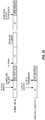
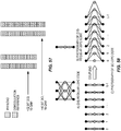
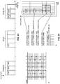
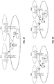
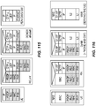
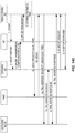
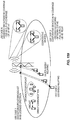
- Figure 1 shows the high level logical architecture for an example system supporting both NX and LTE.
- the logical architecture includes both NX-only and LTE-only eNBs, as well as eNBs supporting both NX and LTE.
- the eNBs are connected to each other with a dedicated eNB-to-eNB interface referred to here as the X2* interface, and to the core network with a dedicated eNB-to-CN interface referred to here as the S1* interface.
- the names of these interfaces may vary.
- CN/RAN core network/radio access network
- the S1* and X2* interfaces may be an evolution of the existing S1 and X2 interfaces, to facilitate the integration of NX with LTE. These interfaces may be enhanced to support multi-RAT features for NX and LTE Dual Connectivity (DC), potentially new services (loT or other 5G services), and features such as network slicing (where, for example, different slices and CN functions may require a different CN design), on demand activation of mobility reference signals, new multi-connectivity solutions, potentially new UP/CP splits in the CN, support for a new connected dormant state, etc.
- DC NX and LTE Dual Connectivity
- LoT or other 5G services potentially new services
- network slicing where, for example, different slices and CN functions may require a different CN design
- new multi-connectivity solutions potentially new UP/CP splits in the CN, support for a new connected dormant state, etc.
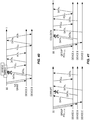
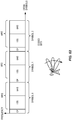
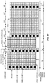
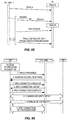
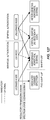
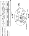
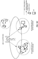
- Figure 2 shows the same logical architecture as Figure 1 , but now also includes an example of an internal eNB architecture, including possible protocols splits and mapping to different sites.
- ECM_IDLE/RRC_IDLE is the primary UE sleep state in LTE for inactive terminals.
- RRC_CONNECTED with DRX is also used, however the UE is typically released to RRC_IDLE after X seconds of inactivity (where X is configured by the operator and typically ranges from 10 to 61 seconds).
- Reasons why it may be undesirable to keep the UE longer in RRC_CONNECTED with DRX include limitations in eNB HW capacity or SW licenses, or other aspects such as slightly higher UE battery consumption or a desire to keep down the number of Handover Failures (KPI).
- the "RRC_CONNECTED with DRX” state is enhanced in NX to become the primary sleep state.
- the enhancement includes adding support for UE controlled mobility within a local area, thus avoiding the need for the network to actively monitor the UE mobility. Note that this approach allows for the possibility that the LTE solution can be further evolved to create a common RRC Connected sleep state for NX and LTE.
- RRC_CONNECTED DORMANT (or RRC DORMANT for short):
- RRC ACTIVE RRC_CONNECTED ACTIVE
- This state is optimized for data transmissions, but allows the UE to micro-sleep, thanks to DRX configuration, for scenarios when no data is transmitted but a very quick access is desired. This may be referred to as monitoring configuration within the RRC ACTIVE state.
- monitoring configuration within the RRC ACTIVE state.
- the UE cell or beam level mobility is controlled and known by the network.
- NX Considering tight integration between NX and LTE, (see Section 2.7) the desire to have a RAN controlled sleep state in NX drives requirements to also support a RAN-controlled sleep state in LTE for NX/LTE capable UEs.
- a common S1* connection is desirable for LTE and NX. If a RAN-controlled sleep state is introduced on the NX side, it would be very beneficial to have similar sleep state on the LTE side, also with an active S1* connection, so that the sleeping UE can move between NX and LTE without performing signaling to setup and tear down the S1* connection.
- This type of inter-RAT re-selection between LTE and NX may be quite common, especially during early deployments of NX.
- a common RAN based sleep state called RRC_CONNECTED DORMANT should be introduced in LTE. The UE behavior in this state is similar to what is defined for LTE RRC suspend/resume, however the paging is done by the RAN and not by the CN, since the S1* connection is not torn down when RRC is suspended.
- a common RRC_CONNECTED ACTIVE state between NX and LTE is desirable.
- This state is characterized in that the NX/LTE capable UE is active in either NX or LTE or both. Whether the UE is active in NX or LTE or both is a configuration aspect within the RRC ACTIVE state, and these conditions need not be regarded as different sub states, since the UE behavior is similar regardless which RAT is active.
- the UE is configured to transmit data in one and to perform measurements in another one for dual-connectivity and mobility purposes. More details are given in section 2.
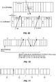
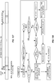
- Figure 3 shows the UE states in an LTE/NX where LTE supports the common RRC_CONNECTED ACTIVE and RRC_CONNECTED DORMANT states discussed above. These states are described further below.
- RRC Radio Resource Control
- RRC is a signaling protocol used to configure and control the UE.
- RRC relies on lower layers for security (encryption and integrity protection), segmentation and reliable in-order delivery of signaling messages. No detailed assumptions are made regarding when an RRC message is delivered that makes the RRC messages asynchronous to the radio timing.
- RRC is suitable for messages of any size requiring reliable delivery such as UE configuration.
- NX RRC Many of the same basic functions and procedures as defined in LTE RRC are also used in NX RRC, like security and connection control, measurement configuration, etc. However, new functionalities are described herein.
- One new functionality is that the RRC protocol handles both NX standalone operation as well as NX and LTE joint operation, while keeping the NX and LTE related configurations of lower layers self-contained. Further design principles to realize the tight integration from the RRC point of view are:
- NX RRC new functionalities of NX RRC include support for the new dormant state, as discussed in Section 1, and new ways to deliver system information, see chapter 3.2. Beam-based mobility management, as discussed in chapter 3.5, may drive additional changes.
- a new framework for UE capability signaling is described in section 2.1.5.3.
- RRC is involved in the Non Access Stratum (NAS) message exchange between UE and CN, and provides various control-plane functions both on UE and eNB:
- NAS Non Access Stratum
- the split architecture with RRC terminated in a centralized node also impacts functions supported by RRC. Some functions are less suitable for a centralized implementation far from the air interface, for example:
- NX identifiers involved in RAN L3 procedures (in particular RRC procedures), which are relevant to describe. These identifiers may be critical for the procedure as such, or they may be identifiers used by other layers or functions and simply transported by a RAN L3 message. The latter are of course less relevant to bring up in this context, but in some cases they deserve to be mentioned.
- C-RNTI Cell Radio Network Temporary Identifier
- the UE RRC context identifier identifies a UE's RRC context in the RAN and hence it is unique within the entire RAN. In the case of a common RRC entity the UE RRC context identifier is valid for both LTE and NX.
- the network can give the UE RRC context identifier to the UE at any time while the UE is in active state. The network may, for example, choose to do it in conjunction with the RRC connection setup (see section 2.1.5) when the context is created, in order to ensure that UE has it in case it would lose the connection (e.g., in case of radio link failure).
- the network may choose to transfer the UE RRC context identifier to the UE when the UE is put in dormant state, to avoid the control overhead of having to reallocate a UE RRC context identifier in the UE every time the UE moves to a new RAN node.
- the UE RRC context identifier is used for context fetching between RAN nodes in potential procedures such as dormant to active state transition (see Section 2.1.5.6), Tracking RAN Area Update in dormant state and radio link failure recovery. It should identify a UE's RAN context in an inter-RAN node scenario. That is, it should both identify the RAN node holding the context (e.g., the "anchor node", e.g., Access Node (AN), Radio Controller Function (RCF), or some other kind of controller such as a cluster head) and identify the context within this RAN node. Hence, it comprises an identifier of the anchor RAN node and a local context identifier allocated by the anchor RAN node.
- the identifier of the anchor RAN node is the RAN node identifier described further below. It can be used also in other contexts and deserves its own separate description.
- the local context identifier only has RAN node internal significance. It could be the MAC-id, which is used for addressing the UE for downlink control signaling, but in an ambition to retain independence between identifiers that are used for different purposes, it is preferable that the local context identifier is an identifier separate from the MAC-id. In addition, the required range is different for the MAC-id and the local context identifier. Disregarding possible reuse schemes, the MAC-id range may provide a unique identifier to all UEs that are simultaneously in active state in the applicable area (assumedly an Access Node), whereas the local context identifier range may support all UEs that are in either active or dormant state in a node. The latter may include a substantially greater number of UEs and hence a larger range is desirable for the local context identifier.
- this identifier is to identify the UE when the UE is paged during a RAN internal paging procedure.
- the UE is tightly associated with the already existing UE RRC context. This makes the UE RRC context identifier a natural candidate to be used when paging the UE. Since this tight association makes it unlikely that the dependence to the UE RAN context identifier causes future problems, the UE RRC context identifier can be used for this purpose.
- the UE When the UE responds to RAN internal paging, it has to provide an identifier that makes it possible to locate the UE RRC context.
- a reference to the page message e.g., a page identifier, would suffice, but using a more "self-contained" identifier allows a more flexible page procedure, e.g., where the UE responds to a RAN node that has not been involved in the paging.
- the relation to the UE RRC context makes the UE RRC context identifier a natural candidate to be used for this purpose (especially since the page response may be regarded as dormant to active transition).
- the UE's message to the network in conjunction with dormant to active state transition has to enable location of the UE RRC context. This makes the UE RRC context identifier a natural candidate.
- All of the above described identifiers may be one and the same, since all of them have the ability to locate and identify a UE RRC context in an inter-RAN node scenario.
- a RAN node identifier to be visible across the radio interface is useful for various SON activities, such as Automatic Neighbor Relations (ANR) and recording of mobility in dormant/idle mode to aid radio network planning (see also section 3.9). (It is also possible to use RAN-node-specific MRSs for the purpose of ANR.) It is also useful in the network for context fetching and establishment of inter-RAN node interfaces and connections (e.g., X2*).
- ANR Automatic Neighbor Relations
- a RAN node identifier in some senses corresponds to the eNB ID in LTE
- the RAN node identifier in NX serves similar purposes in NX as the E-UTRAN Cell Global Identifier (ECGI) does in LTE, due to the lack of cell concept in NX.
- EGI E-UTRAN Cell Global Identifier
- the RAN node identifier may be transmitted over the radio interface on as-needed basis.
- no RAN node identifier is transmitted over the radio interface by default, but a RAN node may request the core network to order activation (or the core network may initiate this itself) of RAN node identifier transmissions in a relevant area to support ANR or other SON features.
- the RAN node may indicate in the request which area it wants the RAN node identifier transmissions to be activated in, e.g., defined as a geographical area.
- a dynamically assigned, non-systematically selected RAN node identifier is used across the radio interface instead of a static RAN node identifier.
- the network provides (network internal) translation of the dynamic RAN node identifier into an "actual" static RAN node identifier, which in turn may be translated into an IP address if needed (or the dynamic RAN node identifier may be used directly for IP address lookup).
- the approach with network internal translation of a dynamically changed identifier is similar to the approach described for the Positioning Reference Signal (PRS) (see section 3.10) and a common solution may be used for both cases.
- PRS Positioning Reference Signal
- the Tracking RAN Area Code identifies a Tracking RAN Area (TRA) within a single network, to the extent that such areas are used. It may be used in conjunction with configuration of a UE in dormant state with a list of TRAs and would be regularly transmitted by the network for the UE to keep track of its current TRA, and report location update to the network if the UE moves to a TRA that is not in its configured list of TRAs. As with the Tracking Area Code, no real need for any internal structure is foreseen. See also section 3.2.
- the IMSI modulo 1024 is used as an input parameter to the paging occasion procedure. Its purpose is to distribute the phase of the paging DRX cycle among UEs, so that the accumulative paging load of the UEs is more evenly distributed.
- a parameter with a similar function may be desirable for the RAN internal paging in NX, depending on the procedure that is implemented for paging occasions. Note that this is not an identifier per se, but with the introduction of RAN internal paging it is a parameter that merits discussing.
- the anchor RAN node (the RAN node holding the S1* connection) to generate a 10-bit number (the same number of bits as in IMSI modulo 1024) and configure the UE with it as a part of the paging configuration for a UE in dormant state.
- This number would also be included in the RAN internal paging message distributed from the anchor RAN node to the other RAN nodes that are involved in paging the UE.
- no IMSI related data is stored in the RAN.
- UE RRC context identifier e.g., UE RRC context identifier modulo 1024.
- This has an advantage compared to an arbitrary 10-bit number in that it would not have to be conveyed as a separate parameter to the UE and in the distributed RAN internal paging message, since it would be implicit in the UE RRC context identifier which is anyway included in these messages.
- the core network transfers the IMSI modulo 1024 parameter to the RAN node as a part of the UE S1* context when the S1* connection is established and that this number is used in the same manner as in LTE. If the same paging occasion procedure is used for RAN internal paging of a UE in dormant state and core network initiated paging of a UE in idle state, the paging occasions for RAN internal and core network initiated paging coincide with this alternative. This property can advantageously be leveraged to efficiently deal with error cases where the UE and the network have different perceptions of which state (dormant or idle) the UE is in.
- a virtual beam identifier is an abstraction of a physical beam or a group of physical beams. As such, it is adapted for use by inter node signaling procedures on the network side.
- the virtual beam identifier is involved in activation of candidate target beams in inter-RAN node active mode mobility procedures and in SON procedures.
- This identifier is used internally in the network (not passed to the UE).
- a beam is identified on L1 by a certain, dynamically assigned reference signal, e.g., a Mobility and Access Reference Signal (MRS).
- MRS Mobility and Access Reference Signal
- higher protocol layers have to be able to refer to a beam, or a reference signal, e.g., when RRC is used to configure a UE with the MRSs to measure on during a measurement sequence.
- the reference signal sequence itself is very impractical and a higher layer abstraction is desirable instead.
- some kind of reference or index is preferably used to refer to a reference signal, e.g., a MRS index or a C-RS index. Such an index may be passed between RAN nodes as well as between a RAN node and a UE.
- the PDCP context identifier is relevant in distributed RAN node architecture scenarios where RRC processing and PDCP processing are located in different physical entities, e.g., with PDCP in a Packet Processing Function (PPF) and RRC in a Radio Control Function (RCF) located in physically separate nodes.
- PPF Packet Processing Function
- RCF Radio Control Function
- Such distributed RAN node architectures are not standardized in LTE and hence there are no LTE identifiers to reuse. (Note that a corresponding proprietary identifier in eNB products may be used, and in this case, if desired and unless such an identifier is specified in NX, a product-specific/internal identifier may be reused.)
- the bearer identifier in combination with a UE identifier may be used to identify a certain PDCP context.
- the PDCP context identifier could be assigned according to similar principles as the S1 connection identifier, where each entity assigns its own identifier and informs the other part. The PDCP entity would thus assign its own PDCP context identifier and inform the RRC entity after being contacted by the RRC entity.
- the PDCP context identifier can be used as the reference in both directions, but if an RRC entity can have a relation to multiple PDCP entities, then the PDCP context identifier has to be combined with an RRC context identifier in order for it to uniquely identify the RRC-PDCP entity relation.
- the UE RRC context identifier can be reused for this purpose, and assuming that the distributed entities logically form a distinct RAN node (e.g., a "virtual RAN node"), the local context identifier part of the full UE RRC context identifier suffices. Note that the terms "entity" and "context" should not be confused.
- an "entity” refers to a physical processing entity, e.g., an implementation of PDCP in a physical node.
- a “context” refers to the data associated with a specific instance of PDCP processing, e.g., for a certain bearer or traffic flow of a UE.
- This identifier is used internally in the network (not passed to the UE). Note that the interface(s) that would motivate a PDCP context identifier are currently not standardized. Unless it becomes standardized for NX, this remains a product internal matter and each manufacturer may choose what fits its specific implementation best.
- Context identifiers for lower layer protocols may be relevant in distributed RAN node architecture scenarios, e.g., with RLC and MAC in a Baseband Function (BBF) and RRC in a Radio Control Function (RCF) located in physically separate nodes.
- BBF Baseband Function
- RRC Radio Control Function
- the RRC entity may need references to the relevant entities to be able to configure them appropriately.
- Such distributed RAN node architectures are not standardized in LTE and hence there are no LTE identifiers to reuse. (There may, however, be a corresponding proprietary identifier in eNB products. In this case, if desired and unless such an identifier is specified in NX, a product-specific/internal identifier may be reused.)
- the MAC entity on the other hand, is common for all bearers of a UE, for each connectivity leg in case of dual-/multi-connectivity, so the MAC context identifier in principle only has to identify the UE and, as above, the UE RRC context identifier, or the local part of it, could be reused for this purpose. These identifiers are used internally in the network (not passed to the UE).
- an S1 connection identifier identifies an S1 control plane connection associated with a UE and is valid as long as the UE is in RRC_CONNECTED and ECM-CONNECTED state (eNB UE S1AP ID, MME UE S1AP ID). (With the introduction of the suspend/resume mechanism in LTE release 13, the S1 control plane connection may be kept also when the UE goes to RRC_IDLE state.)
- a corresponding X2 identifier identifies the short-lived UE associated relation between two eNBs during a handover procedure (Old eNB UE X2AP ID, New eNB UE X2AP ID).
- S1 and X2 may be used for the S1* and X2* connection identifiers.
- a similar reuse of the LTE principles may apply also for the S1* and X2* user plane identifiers. These identifiers are used internally in the network (not passed to the UE).
- a network slice identifier identifies a set of network resources constituting a logical network. It may potentially be used to direct user plane and control plane traffic to the resources of the network slice it pertains to.
- Table 1 Identifies a UE RRC context in the RAN. Used e.g., for context fetching. It is slightly similar to the C-RNTI, but has a partly different purpose and lacks some of the dependencies associated with the C-RNTI.
- the UE RRC context identifier may identify the UE RRC context in both LTE and NX.
- UE identifier for RAN internal paging Identifies a UE during RAN internal paging. No correspondence in LTE UE identifier for the UE's response to RAN internal paging Identifies a UE when responding to RAN internal paging.
- Enables context fetching No correspondence in LTE.
- UE identifier for dormant to active state transition Identifies a UE during dormant to active state transition.
- Enables context fetching No correspondence in LTE.
- RAN node identifier Supports various SON functions such as ANR.
- Tracking RAN Area Code Identifies a Tracking RAN Area. No correspondence in LTE.
- Phase distributor for paging DRX cycles (for RAN internal paging) Distributes the phase of the RAN internal paging DRX cycle among UEs, so that the accumulative paging load of the UEs is more evenly distributed.
- RAN internal paging is not used in LTE, but one option is to reuse the IMSI modulo 1024 parameter which is used for core network initiated paging in LTE.
- Virtual beam identifier A virtual beam identifier is an abstraction of a physical beam or a group of physical beams. No correspondence in LTE.
- Beam identifier A beam identifier is used to identify a physical layer beam on higher protocol layers. It may be realized as an index pointing at a reference signal sequence. No suitable correspondence in LTE.
- PDCP context identifier Used to identify the PDCP context in a distributed RAN node architecture. To the extent the bearer concept of LTE is reused in NX, the bearer identifier combined with the UE RRC context identifier may be used.
- Context identifier for lower layer protocol Used to identify the RLC context or the MAC context in a distributed RAN node architecture. To the extent the bearer concept of LTE is reused in NX, the bearer identifier combined with the UE RRC context identifier may be used (or only the UE RRC context identifier in the case of the MAC context). Otherwise only product internal/specific corresponding identifiers may exist.
- S1* and X2* connection identifiers Identify control and user plane connections for S1* and X2*. The same principle (and possibly the same identifiers) can be used as in LTE.
- Bearer identifier Identifies a (radio) bearer.
- Network slice identifier Identifies a set of network resources constituting a logical network. No correspondence in LTE.
- SRBs Signaling Radio Bearers
- RB Radio Bearers
- the same set of SRBs may be defined for NX as used for LTE. This also allows the tight integration scenario, where the same SRBs are used to carry either NX or LTE RRC messages over either NX or LTE lower layers (see Section 1).
- SRBs More specifically, the following three SRBs may be defined:
- RRC messages on SRB1 and SRB2, including those containing NAS or non-3GPP messages, are integrity protected and ciphered by PDCP.
- RRC diversity can be supported by utilizing a common SRB1 and SRB2, which can be split over both RATs, similarly to the split dedicated radio bearers (DRBs) used in LTE Dual-Connectivity (DC), using a common PDCP entity with separate RLC/MAC entities per access.
- DRBs dedicated radio bearers
- DC LTE Dual-Connectivity
- the UE or network does not apply RRC diversity for SRB0 as well as for the initial SRB message sequence during the initial connection setup or connection re-establishment/re-activation until both RATs are configured and security activated.
- SRB diversity is activated, implementation-based dynamic link selection in the downlink can be made by the network on a per PDCP PDU basis.
- mapping rules may be defined in the standard.
- An alternative solution is to use separate SRBs for different RATs, and then have rules in RRC level for when messages should be mapped to what SRB.
- One option is to define an NX specific SRB3, which is then used for NX RRC for procedures that do not need to be coordinated with LTE RRC.
- This entity is used in the non-co-located case located in the NX eNB to deliver NX RRC messages directly between the NX eNB and the UE, without having to be passed via the LTE eNB. Note that from a security point of view, this solution deviates from the DC architecture with a single trusted node terminating all SRBs.
- the secondary eNB needs to be equally trusted and securely implemented as the master eNB. Otherwise an attacker breaking into the secondary eNB could control the UE via RRC from there.
- the tight integration with LTE motivates keeping common radio bearers also for the user plane, allowing the UE to move between LTE and NX coverage without having to reconfigure the bearers.
- new use cases for 5G may drive the introduction of new QoS definitions for NX, and new bearer types. Ideally, those should then be introduced to LTE as well, so that seamless LTE-NX mobility can be supported. In cases where LTE is not capable to provide the required QoS, bearers need to be reconfigured or released when moving from NX to LTE.
- DRX is configured together with paging and the "listening period" is calculated based on the current System Frame Number (SFN).
- SFN System Frame Number
- Each TRA may have a specific DRX configuration which is provided to the UE via dedicated signaling e.g., TRA Update Response or RRC reconfiguration.
- the range of DRX cycles which the network can configure goes up to several hours or even days. Of course, this needs to be taken into account when designing the number of bits to include in the SFN field.
- the RAN may not be able to find the UE. In this situation, the RAN may inform the CN, and the CN may then take over the paging functionality for that UE.
- SSI see section 3.2.2.2
- DRX DRX configuration
- FIG 4 illustrates estimated UE battery life for a UE in dormant state when the network is synchronized for different SSI period and DRX cycles.
- Figure 5 illustrates estimated UE battery life for a UE in dormant state when the network is not synchronized for different SSI periods and DRX cycles.
- a preferred aspect of the architecture described herein is its support for a tight integration of NX with LTE, e.g., as discussed in Section 3.7.
- One part of this tight integration is the RRC layer integration of LTE and NX radio access, to support both the LTE-NX dual connectivity and NX stand-alone operation.
- RRC layer integration of LTE and NX radio access, to support both the LTE-NX dual connectivity and NX stand-alone operation.
- Single RRC protocol is defined as a protocol architecture option, which can integrate all or a subset of the control-plane functions of NX together with the existing LTE RRC protocol functions with a single RRC protocol machine, to provide the functions to enable the LTE-NX dual connectivity and possibly the stand-alone NX operation.
- the NX lEs which can be defined within the LTE RRC specification or in a separate NX RRC specification, may include broadcasted/dedicated system information and security control information elements.
- RRC function e.g., RRM
- RRM radio resource control information elements
- PDCP level split/combining can be used to provide extra reliability (RRC diversity).
- single RRC protocol may have limited flexibility when adding new functions to NX RRC, especially if a single RRC evolution track for both LTE and NX is targeted.
- FIG. 6 An overall protocol stack that includes single RRC operation for LTE-NX DC operation is illustrated in Figure 6 , from the UE and eNB perspectives, respectively.
- the node where the RRC and PDCP entities reside may be either an LTE or NX node.
- Dual RRC protocol refers to a protocol architecture option comprising separate LTE and NX RRC entities, which follow independent control-plane specifications for LTE and NX respectively. Inter-RAT coordination is mandated in the RRC level, to fulfil the LTE-NX tight integration design principle.
- NX RRC messages are tunneled to the UE via the LTE RRC entity and vice-versa for LTE-NX dual connectivity, which is the case whether LTE and NX RATs are co-located or not. Therefore, the RRC containers that carry the NX/LTE RRC messages need to be specified. Furthermore, in order to sustain a single S1 connection and coordinated state transitions between NX and LTE, additional mechanisms may be required as partly to be discussed within the RRC procedures.
- PDCP level split/combining via a single PDCP entity on the control-plane, is assumed to enable RRC diversity and reliable handling of control-plane thereof.
- An additional PDCP entity (for new SRBs), associated to an NX SRB, e.g., SRB3, can also be configured in the NX node for the direct NX RRC message transfer when the common PDCP entity is situated in the LTE node.
- FIG. 7 An overall protocol stack that includes the dual RRC operation is illustrated in Figure 7 , from the UE's and eNB's perspectives, respectively.
- FIG 8 illustrates an overall RRC signaling diagram for LTE-NX dual connection setup, where the dashed lines indicate the involvement of RRC signaling associated with NX (independent from the RRC protocol architecture options).
- Initial RRC signaling includes RRC Connection Request (SRBO) and RRC Connection Setup / Reject (SRBO), and RRC Connection Setup Complete / Attach Request (SRB1) message sequence.
- SRBO RRC Connection Request
- SRBO RRC Connection Setup / Reject
- SRB1 RRC Connection Setup Complete / Attach Request
- the same set of SRBs may be defined for NX as used for LTE. This also allows the tight integration scenario, where the same SRBs are used to carry either NX or LTE RRC messages (or both messages if both are to be set up) over either NX or LTE lower layers.
- the initial connection signaling may also be reused between LTE and NX.
- the UE can select which RAT to perform access based on a predefined criterion.
- the UE may be assigned an UE RRC Context ID (see section 2.1.3.1.1) that is kept when the UE goes to dormant state or updated via an RRC connection inactivation signaling as to be discussed.
- a UE can be indicated as LTE+NX UE within the Attach request, when UE moves from RRC IDLE to RRC CONNECTED mode. Subsequently, the UE can be configured for dual RAT connectivity with a single RRC reconfiguration procedure, as discussed in section 2.1.5.4.
- Figure 9 illustrates a security setup for LTE and NX, assuming a common MME connection.
- Security setup can be optimized by using common capability signalling, single authentication, single key generation and common security mode command as shown, for example, in Figure 9 .
- the common security setup can either be handled by the single RRC or dual RRC protocol architecture option.
- the LTE header indicates the transparent container for NX RRC messages.
- a single PDCP entity can provide a common encryption (as in LTE DC operation) as well as integrity protection for common SRBs. It is also possible to implement a separate PDCP entity, enabling new NX SRBs.
- a new UE capability signaling framework addresses limitations of the 2G/3G/LTE UE capability signaling. More particularly, the new UE capability signaling framework addresses one or more of the following issues:
- a new UE capability framework that addresses these issues includes one or both of the following two elements:
- Figure 10 illustrates features of the UE capability framework described above.
- RRC Connection Reconfiguration message can establish/modify/release radio bearers, configure L1, L2 and L3 parameters and procedures (e.g., for mobility and/or to establishment of dual connectivity).
- RRC Connection Reconfiguration message can be used for single NX connection reconfiguration (similarly to the LTE-equivalent message) as well as for NX multi-connectivity setup as discussed in Section 3.13.
- the RRC connection reconfiguration can be either be network-triggered or UE-triggered.
- a common RRC protocol (e.g., as specified in a future NX release of 3GPP TS 36.331) is responsible for the dual LTE-NX connectivity connection setup procedures.
- the RRC connection reconfiguration procedure for LTE and NX can be handled within a single-round of RRC message exchange as shown in Figure 11 .
- IEs containing the NX configuration are carried in the Setup Response.
- Figure 11 thus illustrates the LTE-NX dual connectivity setup used with the single RRC protocol architecture, where the illustrated signaling is based on the assumption that the first node is an LTE eNB.
- the signaling other way around, where the first node is an NX eNB, would follow the same message sequence.
- one of the RRC protocols can handle the RRC connection reconfiguration procedure, allowing the NX/LTE dual connectivity configuration in a single round of reconfiguration.
- This is shown in Figure 12 .
- This can be done by using the existing PDCP entity and associated security in the node where the control-plane (either LTE or NX) is up and running.
- the RRC messages of the second RAT may be transferred to the UE via the first RAT within a transparent container or directly to the UE via new SRB, such as SRB3.
- Figure 12 illustrates LTE-NX dual connectivity setup for use with the dual RRC protocol architecture with a common RRC reconfiguration procedure.
- the illustrated signaling is based on an assumption that the first node is an LTE eNB.
- the signaling the other way around, where the first node is an NX eNB, would follow the same message sequence.
- This procedure handles the state transition from RRC CONNECTED ACTIVE to DORMANT, which effectively puts the UE to "sleep" in LTE and/or NX.
- the transition can be triggered due to a timer configured by the network or by an RRC Connection Inactivation message sent by the network, which may include the security re-activation information (e.g., nextHopChainingCount ) for the next RRC CONNECTED ACTIVE state.
- the UE Upon receiving this message, the UE enters the RRC DORMANT state. Given a dual RRC for LTE and NX, the message should be defined in both RRC specifications, e.g., using similar IEs.
- Some of the UE RRC configuration in RRC CONNECTED DORMANT could be configurable by the network during the RRC connection setup, inactivation, and re-activation procedures, within which the UE RRC Context Identity can also be assigned.
- the network also ensures that the information for the UE dormant behavior is up to date. This information is especially important in the NX case where the system information is either not broadcasted (e.g., dormant mode mobility parameters) or seldom broadcasted (e.g., AIT, see section 3.2.2.2).
- Updated configuration may also be given to the UE in the RRC Connection Inactivation message, since the UE may have moved to a location with a different dormant state configuration. Other changes to the information in the RRC Connection Inactivation message may be made. For instance, the UE could be configured to camp on MRSs (see Section 3.4.4 for further details) and re-active the connection accordingly. The network could also mandate the UE to keep the MAC identities and associate some timers when moving to dormant.
- the UE Upon entering the RRC DORMANT state (without any additional configuration for optimized state transition), the UE should:
- a lightweight transition is provided, as shown in Figure 13 . If the UE has received the security re-activation information such as nextHopChainingCount in RRC Connection Inactivation, a subsequent RRC reconfiguration procedure is not needed, since the RRC connection re-activation procedure would be able to reconfigure SRBs and DRBs activating the user plane thereof.
- security re-activation information such as nextHopChainingCount in RRC Connection Inactivation
- Figure 13 illustrates a signaling flow for RRC connection re-activation procedure, assuming that the first node is an LTE eNB.
- the signaling other way around, the first node is NX eNB, follows the same message sequence.
- RRC connection re-activation procedure The purpose of RRC connection re-activation procedure is to re-activate the RRC connection, which involves the resumption of SRBs and DRBs.
- the connection re-activation succeeds only if the accessed target node (NX or LTE) can find the UE RRC context and the mobility anchor for S1*. For this reason, the UE RRC Context ID is included within the RRC Connection Re-activation Request that is an SRBO message. This message can be integrity protected to protect the network from the false requests.
- the procedure for instance may be triggered by the UE either in response to a paging, when the UE has UL data in buffer, or when it needs to send TRA updates.
- the UE triggers an RRC connection re-activation procedure, which should be defined in both NX and LTE's RRC specifications when a dual RRC solution is implemented.
- the network Upon receiving RRC Connection Re-activation Request, the network retrieves the UE RRC Context (including the security re-activation information) based on the UE RRC Context ID, performs the necessary mobility actions and responds with RRC Connection Re-activation to reconfigure SRBs and DRBs. Upon reception of this message, the UE performs the following actions:
- NX Several different types of measurements and/or signals are measured in NX (e.g., MRS, SSIs, TRAS, etc.). Mobility events and procedures thus need to be addressed for NX.
- the RRC Connection Reconfiguration message should be able to configure both the NX measurements and the existing LTE measurements for the single RRC option.
- the measurement configuration should include the possibility to configure the UE to measure for NX/LTE coverage e.g., to initiate DC setup or inter-RAT HO (as in the legacy).
- NX There are two different measurement reporting mechanisms for NX, non-RRC based reporting (see Section 2.3.7.2), where the UE indicates the best of a set of candidate DL beams through a preconfigured USS sequence; and RRC-based reporting, which is similar in some respects to the event-triggered LTE measurement reporting.
- RRC-based reporting which is similar in some respects to the event-triggered LTE measurement reporting.
- These two measurement reporting mechanisms are preferably deployed in parallel and used selectively, e.g., depending on the UE's mobility state.
- System information as known from previous releases of the LTE standards consists of very different types of information, access information, node-specific information, system-wide information, public warning system (PWS) information, etc. Delivery of this wide range of information does not use the same realization in NX.
- PWS public warning system
- Desirable features and design principles for NX include one or more of the following. Thus, it should be appreciated that not necessarily all of these may be met by a given implementation.
- system information acquisition resembles, in some respects, that of dual connectivity for LTE.
- the UE accesses LTE first and then activates NX
- the UE receives the NX system information in dedicated transmission, via the LTE RRC, when setting up the NX connection.
- LTE DC this applies to all system information, except SFN acquired from MIB of the Primary Serving Cell (PSCell) of the SCG.
- the SFN may be included in the TRAS (see section 3.2.4.1.3).
- the same principle applies to the other way around: a UE accessing NX first and then activating LTE obtains the LTE system information in dedicated transmission via the NX RRC.
- the paging solution for NX utilizes one or both of two channels: a Paging Indication Channel, and a Paging Message Channel.
- paging configuration (and so DRX configuration) is SFN-based.
- tracking RAN areas are configured at the UE.
- a tracking RAN area is defined by a set of nodes transmitting the same tracking RAN area signal (TRAS). This signal contains the Tracking RAN Area Code as well as the SFN.
- Each TRA may have a specific paging and TRAS configuration which is provided to the UE via dedicated signaling, e.g., via a TRA Update Response or RRC Reconfiguration message.
- the TRA Update Response may, furthermore, contain paging messages. More information on paging can be found in Section 3.2.
- the UE has an RRC connection towards the network and RRC messages are exchanged using the LTE eNB.
- the higher layers the asynchronous functions, e.g., RRC / PDCP
- the network Upon the reception of measurement reports over the LTE link (e.g., containing NX measurements) the network decides upon the establishment of dual connectivity with NX by sending a RRC connection re-configuration message, containing the necessary information for the UE to establish a link towards NX. This message can be seen as a command to the UE to establish a connection towards the secondary eNB (SeNB).
- SeNB secondary eNB
- NX Another scenario is a UE-initiated procedure, where the UE directly contacts NX to establish LTE-NX dual connectivity.
- An example of this approach is shown in Figure 14 .
- Benefits of accessing NX directly include a lower latency procedure and some additional level of diversity (e.g., when the first link is unstable).
- the UE has an RRC connection with the network and uses the link from one of the RATs, e.g., LTE, to exchange RRC messages.
- the RATs e.g., LTE
- the UE then initiates the access towards a secondary RAT (e.g., performing synchronization and random access over NX) and sends via the secondary RAT link (e.g., NX) an RRC message containing a UE context identifier (e.g., the UE RRC context identifier described in section 2.1.3.1) indicating the request to establish dual connectivity.
- a secondary RAT e.g., performing synchronization and random access over NX
- NX secondary RAT link
- an RRC message containing a UE context identifier (e.g., the UE RRC context identifier described in section 2.1.3.1) indicating the request to establish dual connectivity.
- This context identifier contains the location of the anchor point, so that upon the reception of that message the secondary RAT can locate the single control point at the network from where the UE is controlled.
- the network figures that out sends an RRC message to the UE to configure the NX resources for the existing SRBs/DRBs (previously established over LTE) and/or the configuration of novel NX SRBs/DRBs associated to NX.
- the UE-initiated procedure can be applied either for the single or dual RRC case, however, it may be more useful in the dual RRC case where one could possibly have a different RRC reconfiguration procedure over the secondary RAT (NX, in the present example). Note that the fact that this alternative is called UE-initiated does not mean that it is UE-controlled. What triggers the UE to send the request towards the secondary node (NX in the example given) may be an event configured via RRC by the network.
- LTE uses a fixed HARQ feedback timing which is a problem in some implementation scenarios (e.g., with centralized baseband deployment or non-ideal backhaul) and when operating in unlicensed spectrum (e.g., where listen-before-talk sometimes prevents UEs from sending HARQ feedback) ;
- the LTE UL and DL L1 control channels can be improved for better support of high-gain beamforming, as the switches between transmission modes and configurations is unnecessarily hard and slow; there can be a rather long latency coming from the UL scheduling; the DRX behavior is not always optimal; and the design of the scheduling request channel is not as flexible or efficient as desired, for all applications.
- support for reciprocal massive MIMO transmission and massive MIMO beamforming can be made to work better in NX than in LTE.
- Other improvement areas are one or more of dynamic TDD; unlicensed band operation; contention-based access; multi-connectivity; multi-hop; D2D etc.
- NX can provide native and optimized support for increasingly important use-cases such as multi-X (multi-connectivity, multi-RAT, multi-hop, multi-carrier, multi-node, multibeam), UL/DL decoupling, etc.
- all radio links in NX are capable of operating within a bounded set of radio resources (resource slice), thus avoiding that terminals make assumptions on or rely on signals outside these resources.
- the traffic scenarios supported by NX range from a single 100-bit packet every hour all the way up to multiple Gbps continuous data transfers.
- the frequency range to be supported is much wider, ranging from below 1 GHz up to 100 GHz.
- There are wide assumptions on device and node capabilities e.g., from 1 to 400 antennas, from hours to 20-year battery life, etc.).
- Service agnostic design allowing flexible service centric configurations: Different use-cases have vastly diverse requirements. For example, some C-MTC use-cases need extreme reliability with BLER in the order of 10 -9 ; tactile internet services need very low end-to-end latency of 1 ms; extreme MBB benefit from multiple Gbps of user throughput, etc.
- the NX standard provides a large set of service agnostic features which the network may configure and enable to fulfill the service specific requirements. This enables co-existence of multiple services while maintaining low complexity and high efficiency for each service.
- certain services may be operated on dedicated time and frequency resource slices of the radio spectrum. Separating the radio resource in this manner also enables lower complexity implementation and testing in some situations. If a service becomes deprecated in one particular area (e.g., a factory is closed down) then that spectrum can be quickly reassigned to another service, by managing the resource slices assigned to different services. The default assumption is that all services shall be able to coexist on the same carrier but using dedicated resource slices is a solution for support of so-called vertical services. Thus, in NX, any service can be contained within a defined set of radio resources.
- NX has a lean and scalable design that is able to cope with various latencies on the transport and radio interface as well as with different processing capabilities on UE and network side. To ensure this, fixed timing relations are avoided between control messages such as HARQ (MAC), ARQ (RLC) and RRC signaling.
- MAC HARQ
- RLC ARQ
- RRC Radio Resource Control
- control signaling may be optimized by utilizing correlations in traffic. This avoids hard and slow reconfigurations.
- a future behavior e.g., something sent in the downlink there will be uplink traffic a short while later
- the L2 design may take advantage of that: e.g., start with open-loop transmission and do a seamless switch to a closed-loop transmission format once the channel state information becomes available at the transmitter end.
- Layers of coordination When the cost of observation and control becomes too high, e.g., in terms of delay or overhead, scheduling decisions are delegated to nodes and UEs for the time it takes to collect sufficient information and enforce a suitable coordination.
- the centralized resource scheduler still owns and controls the right to use radio resources but in situations where observation and control is easier and more efficient to maintain in another node (e.g., in multi-hop relaying or D2D), the momentary decisions on how to assign resources can be distributed.
- the mandatory transmissions to be done by an NX eNB at specific times are sparse in time and frequency.
- the NX terminal should not expect control messages at specific time/frequency resources (as is the case today for HARQ feedback in LTE).
- the configurability enables forward compatibility as the network can assign resources freely to other (newer) terminals without having to send a massive amount of legacy signals for legacy terminals.
- the NX radio interface may send control information at dynamic time instances.
- a user equipment should be capable of ignoring any "un-defined resources" within the resource slice unless explicitly instructed otherwise.
- "Un-defined resources" may be dynamically configured as a set of periodic patterns in time, and/or in frequency.
- any service should be able to be delivered within a bounded set of radio resources (a resource slice), thus avoiding a design where L1 control channels and reference signals are spread out over the entire system bandwidth.
- the L2 channel structure supports in-band control information, with different channel encoding, modulation, HARQ configuration, etc.
- NX achieves flexibility and scalability by being a system that supports more than one physical channel.
- channels may be regarded as being either direct or re-transmittable.
- a direct channel is denoted dPDCH and the re-transmittable channel is denoted rPDCH.
- the structure of having a direct and a re-transmittable channel is equally applicable to both uplink and downlink transmissions. The difference between such channels is that they may be optimized for different operational points.
- the direct channel may, e.g., be designed for a BLER of 10 -3 without soft HARQ combining, while a re-transmittable channel may target 10% BLER and support several HARQ retransmissions with soft combining in the receiver. Note that here we are referring to channels for processing Layer 2 (L2) data.
- L2 Layer 2
- Some information like downlink control information (DCI) or channel quality information (CQI) feedback may only be relevant if the eNB can decode it upon the first transmission attempt while other type of data, such as user-plane data or RRC control messages, benefit from successful delivery even if that requires multiple HARQ re-transmissions.
- DCI downlink control information
- CQI channel quality information
- One single channel structure optimized slightly differently, caters for both of these very different needs.
- the user-plane data may require much lower error probability than L1/L2 control signaling (e.g., up to 10 -9 for C-MTC and 10 -3 for L1/L2 MBB related control signaling) and in such scenarios we may either make use of two direct channels or one that is configured for the highest requirements.
- L1/L2 control signaling e.g., up to 10 -9 for C-MTC and 10 -3 for L1/L2 MBB related control signaling
- the channels can be referred to with just a number, such as 1 and 2, for example, indicating that they just happen to have different configurations.
- the differently configured channels may be used for different purposes.
- different numbers of physical channels may be used. Since the network decides how to fill a downlink transport block, what MCS to use, and whether or not to perform retransmissions, such a scheme could alternatively be realized with a single channel.
- Figure 15 illustrates how a MAC control element, such as a CSI report or an UL grant, can be mapped to a direct or re-transmittable channel. It should be appreciated that whether to transmit any given information element on a low-delay optimized (and more expensive, generally) direct channel or on a high-spectral-efficiency re-transmittable channel is a scheduler decision in NX.
- a bootstrapping resource that, e.g., can be used to schedule an initial channel use, is desirable.
- a physical downlink control channel (PDCCH) is defined, where the UE receiver blindly searches for the PDCCH in a pre-defined or semi-statically configured search space.
- the usage of this PDCCH is depicted in Figure 16 . Note that it is possible to use this physical control channel more or less as in the current LTE system, e.g., it can be used every TTI to schedule DL and UL transmissions.
- an important use of the PDCCH in the NX context is to support a shift towards having a larger part of the dedicated user data and the associated L1/L2 control information transmitted with aggressive beamforming.
- the PDCCH is used in NX to enable high gain beam-forming and in-beam transmission of control information.
- the PDCCH is designed to be robust and simple and has a separate set of demodulation reference signals in order to support a different (typically wider) beamforming than the PDCH.
- the PDCCH for NX is designed to be lean and simple. In order to quickly resume transmission in this fallback scenario, the PDCCH is very robust and optimized for a wider coverage area. This implies lower antenna gain and higher cost per bit. But, this enables the majority of the control information to be sent "in-beam".
- the PDCCH also enables transmission of control information before CSI is available, e.g., as an initial bootstrap channel. Since the transmission of control information on the PDCCH is typically more expensive (due to the lower beam-forming gain), only a limited set of simple DCI formats are supported, containing only a small number of bits. This is not a restriction in practice, since without CSI and during the very beginning of a transmission burst (e.g., during the TCP slow start), advanced procedures that requires a lot of control information are not performed anyway.
- UE multiplexing on a shared control channel requires a number of blind decoding attempts. But, by not using the PDCCH as much, the overall number of blind decoding attempts that the UE needs to perform is reduced. Most UEs receive their control information in-beam on the "directly decodable" data channel, most of the time, which gives better control of how to multiplex control information to different UEs.
- new DCI formats may be added only to the in-beam "directly decodable" channel and not on the PDCCH, in some cases. This makes it possible to extend the control channel functionality in NX without changing the shared PDCCH. More specifically, NX can be extended in a manner where new DCI formats are added only to the dPDCH and not the PDCCH.
- PDCCH Physical Downlink Control Channel
- dPDCH uses the same demodulation reference signal as the data channel (rPDCH) while the PDCCH uses a different DMRS.
- rPDCH data channel
- Both the PDCCH and the dPDCH/rPDCH can be beam-formed towards the UE.
- Both the PDCCH and the dPDCH/rPDCH can also be transmitted in a wide beam or with a diversity based beam-former.
- the PDCCH is primarily designed to be used when very accurate CSI information is not available in the base station, such that the base station cannot perform reciprocity-based beamforming.
- the PDCCH uses a DMRS that is typically shared by multiple UEs. It is designed to rely more on frequency diversity than on antenna diversity and can therefore be used in NX deployments with a small (e.g., 2 or 4) number of antennas.
- the dPDCH/rPDCH channels are primarily designed for supporting reciprocity-based beamforming and dynamic TDD (UL RRS based).
- UL RRS dynamic TDD
- DL DMRS are not needed in theory, but in practice downlink demodulation reference signals may also be used in this case, since perfect and absolute UL/DL calibration is not practical.
- the PDCCH does not rely on UL reciprocity reference signal (RRS). It is time-multiplexed with dPDCH/rPDCH in order to support hybrid beam-forming.
- RRS reciprocity reference signal
- One reason why the messages on the PDCCH should be small is that otherwise experience coverage problems of this channel may be a bottleneck in higher frequency bands. If coverage of the PDCCH on high frequency bands is a concern, then PDCCH can be provided only on a lower frequency band, with the dPDCH/rPDCH being used on a higher frequency band. The transmission of UL RRS on the high frequency band that enables reciprocity based beamforming of dPDCH/rPDCH can then be controlled by the PDCCH on the low frequency band.
- the search space on PDCCH supports user-multiplexing, link-adaptation, and rate-adaptation.
- the search space of the dPDCH does not need to support user-multiplexing.
- Figure 17 illustrates, on the left-hand side, how the PDCCH may be used to dynamically update the DCI search space in the UE.
- the middle portion of Figure 17 shows that there is no need to send a search update to the UE when not changing the start location of the DCI search space.
- Figure 17 shows that when changing starting location of the dPDCH (the UE DCI search space), a forward DCI is used. This may cause error propagation
- the bottom portion of Figure 17 depicts the case where a DCI is received in-beam, on a scheduled resource.
- This can be enabled by extending the UE search space for downlink control information to also include resources that need to be dynamically scheduled.
- the UE receives a DCI 0 on the PDCCH, which points out where to start searching for additional control information.
- the UE may find the control information relevant for this TTI (DCI 1 ).
- the PDCCH schedules only the search space extension and not the actual DCI.
- the middle part of Figure 17 indicates that the UE may continue to search in the same location, for multiple TTIs.
- the actual physical data channel assignment may move without enforcing the dynamic search space of the UE to be changed.
- the UE may still perform a number of blind decoding attempts in order to enable rate and link adaptation of the dPDCH.
- So-labeled boxes indicate the usage of a bootstrap channel (e.g., PDCCH or a contention-based physical data channel), lightly-shaded boxes indicate a directly decodable PDCH, while more darkly-shaded boxes indicate a re-transmittable PDCH.
- a bootstrap channel e.g., PDCCH or a contention-based physical data channel
- lightly-shaded boxes indicate a directly decodable PDCH
- more darkly-shaded boxes indicate a re-transmittable PDCH.
- the NW may re-transmit the DCI for the second DL TTI using the PDCCH. This is depicted in the middle part of Figure 18 .
- the UE In the event that the UE expects to receive an UL grant but does not receive any, then it might use a pre-scheduled contention-based resource instead.
- the use of a contention-based uplink channel instead of a scheduled dedicated channel is an indication that the first dPDCH decoding has failed (see bottom part of Figure 18 ).
- the network may also request the UE to send explicit and event triggered reports on the detection success of dPDCH transmissions.
- An example of this is shown in Figure 19 , which shows that when scheduled in the UL, the UE can report back the reception success of the dPDCH in previous TTIs.
- this extra level of error-propagation termination might not be necessary, in a given implementation.
- the search space for downlink control information is thus dynamically updated by means of DCI signaling.
- the DCI may be transmitted directly on a downlink physical control channel (PDCCH) or embedded in a MAC control element inside a scheduled downlink data channel (typically the dPDCH).
- PDCH downlink physical control channel
- MAC control element inside a scheduled downlink data channel (typically the dPDCH).
- UE search space modifications such as add/delete/move may be signaled explicitly, e.g., in a previously received DCI or MAC control element.
- the search space modifications may also be implicit, e.g., by automatically extending the UE search space to include locations used for DCIs in the previous N TTIs or by automatically delete the oldest UE search space location when a new search space location is added.
- in-beam control channels relies on having the same dedicated demodulation reference signal (DMRS) for both the dPDCH and the rPDCH.
- DMRS dedicated demodulation reference signal
- Figure 20 illustrates an example of using a single set of terminal specific demodulation reference signals (four shaded regions having 8 resource elements each) for demodulation of two physical channels, the dPDCH and the rPDCH.
- the illustration in Figure 20 looks similar in some respects to how in LTE the CRSs are used as common reference signals for demodulation of PDCCH and PDSCH.
- the CRSs in LTE may be beamformed, e.g., by down-tilting of the antenna, the beamforming cannot be changed dynamically with respect to a particular UE, since there are other UEs measuring on the CRSs.
- ePDCCH + DMRS on PDSCH in LTE two sets of reference signals are used, leading to higher pilot overhead.
- CRS-based transmission in LTE (PDCCH+PDSCH TM4) is used, then there is no option of dynamically beam-forming the reference signals towards the receiving user.
- the total system bandwidth is signaled on the PBCH.
- NX it is not assumed that a user is aware of the system bandwidth.
- a notion of a user-specific bandwidth is still desirable, e.g., for channel filtering and signaling purposes.
- the BW that a UE is operating within is here defined by a "resource partition".
- a resource partition is a time-and frequency subset of radio resources in which we can define radio links and transmission modes.
- One property of a resource slice is that it can be semi-statically re-configured (which in not the case for the "system bandwidth" in e.g., LTE).
- An NX radio link can thus have one or more physical data channels (e.g., dPDCH and rPDCH) in each direction (UL and DL) and the scheduling entity also has access to a physical control channel (PDCCH) used for transmitting control information only.
- the MAC structure of each physical channel is the same for UL and DL.
- An example with two PDCHs, the first one having 1 transport block (TB) and the second one having two transport blocks is depicted in Figure 21 .
- Each channel has a MAC Header and a payload part containing MAC Elements.
- the MAC elements are either Control Elements or MAC SDUs (service data units).
- Figure 21 shows the basic MAC channel structure of NX.
- a lean and simple boot-strap channel denoted physical control channel (PDCCH) is used to initiate a packet exchange flow.
- a first or “directly decodable” physical channel (denoted dPDCH) carries primarily in-band control information.
- a second or “re-transmittable” physical data channel (denoted rPDCH) carries primarily user-plane and control-plane data. Both physical data channels are assumed to re-use the transport channel structure of LTE.
- the content of the MAC sub-headers are, in principle, the same as for LTE today.
- the sub-header can consist of 1, 2, or 3 bytes of information.
- the structure [R/R/E/LCID] is used for fixed length MAC SDUs and fixed length MAC Control Elements, and the structure [R/R/E/LCID/F/Length] is used for variable length MAC SDUs and Control Elements. This is shown in Figure 22 , which shows how the transport channel structure and MAC-header format from LTE is re-used also for NX.
- the logical channel ID is defined in separate tables for UL and DL.
- NX follows the same general approach.
- Figure 23 shows examples of how the LCID tables can be updated for UL and DL, where some additional LCIDs in NX are shown.
- DCI downlink control information
- the DCI can, just as in LTE today, be used to assign an UL grant, schedule a DL transmission, or to send a power-control command.
- the DCI is extended to also support a command for transmission of reference signals, such as UL reciprocity reference signals (RRS), denoted RS transmission command in Figure 23 .
- RTS UL reciprocity reference signals
- DCI Downlink Control Information
- HARQ feedback in a MAC control element is enabled. This in turn enables introduction of new feedback schemes such as selective repeat or schemes where more than one feedback bit per process is used. Also, a LCID for CSI feedback is introduced as well as an entry for reference signal measurement feedback. Note that not all LCIDs are relevant in all cases. Some are mostly relevant in the DL while some are mostly relevant for the UL.
- FIG 24 is shown a downlink example in which two PDCHs are configured.
- the figure shows a downlink channel structure example comprising a physical control channel (PDCCH), a first "directly decodable” physical data channel (dPDCH) and a second "re-transmittable physical data channel (rPDCH).
- the dPDCH does not use soft combining of HARQ re-transmissions and it can only carry a single transport block (TB 1 ) while rPDCH does support HARQ and supports transmission of up to two transport blocks (TB 2 and TB 3 ).
- the downlink PDCCH can transmit DCI and possibly also some other MAC-control elements embedded into one transport block TB 0 .
- the UE identity is implicitly (or explicitly) encoded in the CRC of the downlink PDCCH. Note that a difference between the downlink PDCCH and any of the PDCH channels is that the downlink PDCCH cannot carry any MAC SDUs. Furthermore, the downlink PDCCH is blindly decoded by the UE while the PDCH channels are scheduled (implicitly, semi-persistent or dynamically).
- FIG. 25 A corresponding example for the uplink is depicted in Figure 25 , which illustrates an uplink channel structure example comprising a physical control channel configured for contention-based access (cPDCH), a first dynamically scheduled "directly decodable” physical data channel (dPDCH) and a second dynamically scheduled "re-transmittable physical data channel (rPDCH).
- cPDCH contention-based access
- dPDCH directly decodable physical data channel
- rPDCH re-transmittable physical data channel
- the uplink does not have any scheduler but instead a priority handler entity that selects data from the logical channels and controls the MAC Multiplexing within the grants provided. Since there is no scheduler, there is no need for any PDCCH channel either. Instead, the UL transmitter has a channel cPDCH that is primarily intended for contention-based use. A difference between cPDCH and the other two uplink physical data channels (dPDCH and rPDCH) is that they are granted differently.
- the contention-based channel uses a semi-persistent grant that may be assigned also to other UEs. Therefore, the UE identity is encoded onto the channel (implicitly in the CRC or explicitly using a MAC Control Element with LCID 11000; see Figure 23 ) whenever cPDCH is used.
- the UE may send a scheduling request (e.g., a buffer status report) on cPDCH.
- a scheduling request e.g., a buffer status report
- the UE may also include user-plane data when transmitting on that channel. Note that channels carrying system access information and signals such as the PRACH are not included in the illustrated structure in Figure 25 . Should the UE not have a valid grant for any channel, then transmitting a PRACH pre-amble is an alternative (see section 3.2 for further details).
- the "direct channel” (dPDCH) and the “re-transmittable channel” (rPDCH) may be scheduled in a dynamic fashion. When using granted resources on these channels, it is assumed that the receiver knows who is transmitting, and hence no UE identity needs to be embedded.
- the basic PDCH structure in Figure 21 works for both UL and DL, for a typical mobile broadband use case.
- the UL and DL radio links may be configured slightly differently, e.g., without any second "re-transmittable" data channel. By granting resources in different manner and by embedding user identities on some channels and not on other channels, many different use cases can be supported.
- contention-based channels are not special in any particular way. Whether a resource is "dedicated” or not becomes irrelevant in some scenarios, e.g., when massive MIMO or high-gain beamforming is used to enable spatial multiplexing. When resources can be spatially separated, time/frequency resources need to be "dedicated,” and consequently the receiver in the base station should be able to derive who the transmitter is. On contention-based channels a UE identity is embedded in the channel, while on dedicated channels this is not needed. The idea here is that different physical channels have different properties. Different channels may use different sub-sets of a large common transmission format table (e.g., different channel encoders). Continuing with the example in Figure 25 , for instance, three PDCHs may be configured as follows:
- Resource allocation can be simplified in NX, especially when the nodes are equipped with many antennas. This is due to so-called channel hardening, which essentially means that after the application of an appropriately chosen precoder to the transmitted signal, the effective wireless channel between the transmitter and the receiver looks frequency-flat (see section 3.4.4.3), and therefore advanced frequency-selective scheduling might not be needed in NX.
- channel hardening essentially means that after the application of an appropriately chosen precoder to the transmitted signal, the effective wireless channel between the transmitter and the receiver looks frequency-flat (see section 3.4.4.3), and therefore advanced frequency-selective scheduling might not be needed in NX.
- the network can control the usage of radio resources by means of explicit assignment signaling. Scheduling assignments can be sent on a dedicated control channel or in-band, as a MAC control element, for future subframes.
- Maintaining a flow of scheduling assignments may be particularly efficient for reciprocity-based Massive MIMO, where control signaling using valid CSI is significantly more efficient than sending control signaling without CSI. Both dynamic and semi-persistent allocation of resources is possible. At least for semi-persistently allocated resources, it is possible to configure the option of not using the allocated resource if there is no data or control signaling to send in the given timeslot.
- NX A number of different reference signals are provided in NX, for channel estimation and mobility. Both the presence of the reference signals as well as the measurement reports are controlled by the scheduler. The presence of signals can be dynamically or semi-persistently signaled to one or a group of users.
- reference signals for active mode mobility can be dynamically scheduled.
- a UE is then assigned with a search space for mobility transmissions. Observe that this search space is potentially monitored by one or more UEs and/or transmitted from one or more transmission points.
- Scheduled reference signal transmissions (such as MRS) contain a locally unique (at least within the search space) measurement identity in the data message, and reuse some or multiple of the pilots in the transmission both for demodulation and measurement purposes, implying that it is a self-contained message. Further details on reference signals are given in section 2.3.
- Rate-selection is also performed by the network, to benefit from coordination features enabling better prediction of the channel state.
- Different NX use-cases and scenarios have very different link adaptation input and requirements.
- power (or path-loss) estimates and sounding signals are desirable.
- downlink link-adaptation both uplink (reciprocity) and downlink pilot-based estimation are desirable.
- the CSI concept from LTE with CSI-processes and CSI-RS and CSI-IM (for interference measurements) may be maintained (see section 3.4).
- the CSI-RS transmission and measurements are controlled from the scheduler, in both time and frequency.
- the CSI-RS can be kept in-band together with data transmissions, but in some scenarios explicit signaling of CSI-RS is desirable, e.g., for sharing of CSI-RS resources between users.
- CSI-IM and interference reporting is also used, for reciprocity-based beam forming.
- Buffer estimation is used to support uplink scheduling.
- Data notification can be done using a data transmission on a pre-assigned resource or using a single (or few) bit indication on an uplink channel. Both of the options can be either contention-based or contention free, e.g., a semi-statically configured contention-based UL channel or a dynamically scheduled directly decodable UL channel may be used for this purpose.
- An existing data resource can provide a lower latency, while the scheduling request bit enables better control of the radio resources and potentially better spectral efficiency.
- a scheduling request channel may not be needed in NX if the regular uplink channels, potentially using code-division, are sufficient.
- scheduling requests are transmitted implicitly, by means of transmitting pre-defined UL reference signals (such as an RRS), or explicitly, by means of using a pre-granted cPDCH channel.
- Scenarios like multi-hop and multi-connectivity may lead to multiple controlling nodes for one served node. Coordination of the controlling nodes is important, where the controlled node can be used for some of the decision making, for example for selecting between conflicting assignments or to distribute state information to controlling nodes. For observability, the outcome of any distributed decision making may be fed back to the controlling nodes.
- interference With a higher usage of directional beamforming, interference is expected to be bursty to a higher degree. This property provides a larger potential for coordination gains through coordinating the spatial usage and utilizing the extra degree of freedom for interference control in the few cases where it is needed.
- interference can come from a large number of different sources, e.g., normal neighbor node signals, pilot pollution in reciprocity based MIMO, UE2UE and BS2BS interference in dynamic TDD and side-link communication, and other systems in shared spectrum bands.
- sources e.g., normal neighbor node signals, pilot pollution in reciprocity based MIMO, UE2UE and BS2BS interference in dynamic TDD and side-link communication, and other systems in shared spectrum bands.
- a set of measurements is desirable.
- UE-triggered reports on experienced interference or high received power of a given sequence are suitable.
- the use of CSI-reports measured on CSI-RS/-IM is preferable.
- UEs may monitor one or more group-scheduled messages in addition to the dedicated messages. This is done by configuring the UE to not only monitor DCIs for a UE-specific CRC (typically the UE temporary identity is used to mask the CRC), but also for one or more group CRCs.
- a UE-specific CRC typically the UE temporary identity is used to mask the CRC
- Figure 26 shows an example where UE 1 is assigned resources containing additional CSI reference signals, and more generally illustrates an example of using group scheduling to distribute information about dynamically available reference signals (CSI-RS in this example).
- CSI-RS dynamically available reference signals
- These reference signals may be useful also for other UEs and for that purpose a group scheduled message may be transmitted on e.g., the PDCCH to enable non-scheduled UEs to receive and measure on the CSI-RS signals.
- interference control When there is high-gain beamforming, one or more of three aspects may be considered in interference control.
- the first is that the interfered area from a narrow TX beam is much smaller than from a wide beam.
- the second is that high-gain receiver beamforming is strong for rejecting interference.
- the third is that the interfered area by a narrow TX beam may have high interference power density.
- the first is that the number of considerable interferers for one victim receiver may be very few, most probably only a single considerable interferer at any given time; the second is that the experienced interference of a victim receiver may vary largely and quickly, depending on whether the transmitter of the aggressor link is transmitting or not.
- the interference control in NX considers the above characteristics:
- ADSS Directional Sounding and Sensing
- ADSS Directional Sounding and Sensing
- DLIM Directional Link Interference Map
- DSSI Directional Sounding and Sensing Interval
- DSSP Directional Sounding and Sensing Period
- each transmitter transmits one link-specific beam-formed sounding signal over the configured Sounding Resource Unit (SRU) in its link direction, and each receiver keeps a sensing state in its link direction for all possible sounding signals over all SRUs.
- SRU Sounding Resource Unit
- Each link receiver reports the measured results (periodical or event-triggered), including the interfering link identity and the corresponding interference level. Based on the collected measurement results, the network can derive the DLIM.
- Figure 27 shows a time-frequency pattern for ADSS, showing the ADSS pattern and the dimension of DSSI for ADSS (T for Tx DSSW and R for Rx DSSW).
- the DSSP (the effective time of the DLIM) depends on the various factors: the UE moving speed, the beam width of the TX beam, the deployment and dimension of access nodes.
- the DSSP may be 203 ms (outdoor) and 389 ms (indoor) and the overall overhead is much less than 1%, for example.
- the ADSS can be either a separate process or a jointed process with other channel measurements. The following solution assumes that the ADSS is a separate process.
- DSSI Directional Sounding and Sensing Windows
- each AP owns one TX DSSW (TDSSW) for sounding signal transmission for the links plus N-1 RX DSSWs (RDSSW) for sensing of the sounding signal from neighboring links. Deafness of ADSS is conquered via such dimensioning and the missed interference is avoided.
- ADSS may be further developed to reduce overhead so that frequent ADSS can be applied for burst-like traffic, for instance, sharing the same process between ADSS and channel measurement is one way to share the overhead.
- the reporting overhead may be reduced as well by well-defined trigger condition. Decentralized and reactive directional interference sounding and sensing is also possible. In the event that there is no central controller or the interference occurrence is rare, this method may be useful.
- the ADSS is attractive in multiple aspects.
- a first one is that the access link and the self-backhaul link are measured via the same process. The sounding results can be used for the backhaul route (capacity and path) management.
- a second is that all types of interference (AP-to-AP, UE-to-UE, AP-to-UE and UE-to-AP) are measured via the same process. There is no need for multiple types of sounding signals, which is attractive for both TDD and FDD systems, especially for dynamic-TDD system.
- a third aspect is that via certain alignment between co-existing networks in shared spectrum bands, inter-network interference awareness may be achieved via ADSS.
- contention-based access can provide lower delay for initial uplink transmissions and in relay nodes. This is shown in Figure 28 . As shown at the top of Figure 28 , scheduled-based access is contention free, and the performance is superior in high load scenarios. As shown at the bottom of Figure 28 , contention-based access can provide lower delays for initial uplink transmissions and in relay-nodes with a large delay to a central scheduling unit.
- the contention-based uplink channel cPDCH is very different from the normal contention-free uplink channels dPDCH and rPDCH.
- a UE needs a grant to transmit on the cPDCH, but it is not forced to use the grant in case it does not have any uplink data to transmit (in the event that the UE has a grant for a dPDCH/rPDCH and it has no data, it should fill the grant with padding).
- the UE When utilizing a cPDCH the UE should include a temporary UE identity (this may be 24 bits long in NX, for example), so that the receiving base station knows from who the transmission originates. The UE should also add a sequence number to indicate the HARQ buffer that the data comes from. This is because the grants for the dPDCH/rPDCH transmissions include a HARQ process ID and a new data indicator, which the grant for the cPDCH does not.
- the contention-based channel cPDCH does not support soft-combining of HARQ re-transmissions, something that is supported on the dynamically scheduled and contention free rPDCH (see sub-section 2.2.8 for further details).
- Transmissions on the cPDCH may interfere with other channels, primarily since the UL synchronization in the UE may not be as accurate when this channel is used. Solutions to this may be implementation-specific.
- the scheduler may, for example consider the need for guard bands towards contention-free channels and ensure that the performance is good enough. Furthermore, since some poorly synchronous UEs will have a random timing offset, the actual transmission time may have to be significantly smaller than the uplink resource allocation in some cases. Note that when using massive MIMO beam-forming, there are spatial ways to handle the interference.
- Transmissions on cPDCH may also be restricted by additional access rules such as listen-before talk, and this could apply to both shared and dedicated spectrum scenarios.
- dynamically scheduled transmissions dPDCH/rPDCH
- NX is designed to prioritize scheduled access over contention-based access in a slotted manner by adding a listen-before-talk (LBT) period in the beginning of each sub-frame. If a specific reference signal, or energy above a threshold, is detected in this period, then the sub-frame is assumed to be occupied and the contention-based transmission is deferred.
- LBT listen-before-talk
- NX utilizes contention-based access primarily when the time required to maintain coordination increases delay.
- Figure 29 shows that prioritization between scheduled data and contention-based data access is enabled by having the scheduled data starting earlier than contention-based data. This enables the contention-based access to detect the scheduled data transmission using carrier sense. Additional prioritization between different contention-based accesses is also possible, by having different length of the carrier sense period starting from the beginning of the sub-frame.
- a clear-to-send (CTS) signal may be added.
- CTS clear-to-send
- FIG 30 illustrates contention-based access with collision avoidance utilizing both listen-before-talk (LBT), to prioritize scheduled transmissions, and clear-to-send (CTS), to resolve hidden node problems.
- LBT listen-before-talk
- CTS clear-to-send
- the contention-based transmission is then divided into two time intervals, where an indication if the second part is allowed to be transmitted is derived by the reception of a CTS signal from the network in the time between the two time intervals.
- the time between the two (transmission) time intervals is referred to as the interruption time.
- NX channels with contention-based access thus use the following protocol for collision avoidance:
- the first contention-based transmission may be seen as a scheduling request (SR) or a request-to-send (RTS) transmission. Since the mobile terminal may have additional information about the current channel use (e.g., by detecting interference and or PDCCH transmissions from other nodes) one option in NX is to indicate in the RTS signaling which resources that the mobile terminal would like to utilize. This is denoted “selective-RTS (S-RTS) and can be further extended with an adjusting-CTS (A-CTS) message from the network.
- S-RTS selective-RTS
- A-CTS adjusting-CTS
- FIG 31 illustrates an example of a proactive RTS/CTS scheme with selective-RTS (a scheduling request containing a physical resource proposal) and adjusting-CTS (an uplink transmission grant).
- User terminals base the S-RTS resource selection on a capability to monitor multiple downlink physical control (PDCCH) channels (configured in the "PDCCH monitor Set" message from the serving node).
- the S-RTS may be based on the terminal being reactive or proactive when selecting resources that it wants to use.
- the selection can be based on, e.g., interference measurements (re-active); or control channel decoding (pro-active).
- an adjusting-CTS message from the network is useful also in e.g., multi-connectivity scenarios, e.g., the network mode may already be using some of the resources selected by the mobile terminal in some other connection.
- Multi connectivity is a use-case that puts particular requirements on the protocol design. It is clear that multiple streams can be maintained on different layers of the protocol-stack dependent on the ability to coordinate the buffer handling.
- one base station controls one carrier, but is using multiple codewords.
- ARQ where utilized, may be placed before or after the splitting.
- splitting/merging can be done on different levels, in-order delivery, where utilized, operates above the highest split.
- the current HARQ feedback protocol of LTE relies on fast but error-prone single bit feedback with a fixed timing. Since it is far from 100% reliable, the higher layer RLC AM is required to ensure reliability, something which adds delay. Also, the current HARQ protocol is based on many strict timing relations (such as e.g., as per-HARQ buffer synchronous timing), something which is very inflexible and causes several problems when e.g., operating using Dynamic TDD.
- the HARQ protocol should be fast, have low overhead, be reliable, and not require fixed timing.
- the RLC retransmission protocol is still desirable, to efficiently support multi-hop and mobility scenarios.
- L2 protocol architectures result in different design options for L2 functionalities regarding multi-hop communications, such as the ARQ or routing.
- NX For NX, a two-layered ARQ structure is kept, as is done with RLC/HARQ in LTE. Differences from LTE are in the HARQ re-transmission layer, which is fast and low-overhead, but also reliable and not requiring fixed timing.
- the improved HARQ protocol has one or both of two components:
- RLC ARQ which is similar to the current LTE RLC AM ARQ, may also be applied.
- FIG. 32 An illustration of the ARQ structure is shown in Figure 32 . Shown in the figure is an improved ARQ process for single-hop NX. As discussed above, the HARQ protocol illustrated in Figure 32 utilizes two different feedback mechanisms: one "Super-Fast" (A) and one "Scheduled” (B). On top of this, an RLC layer (C) handles residual errors (e.g., due to mobility) and re-segmentation.
- A Super-Fast
- B switcheduled
- the "Super-Fast HARQ" feedback (A) is designed to be lean and it is transmitted as soon as possible. It provides feedback for one or a few downlink transmissions.
- the feedback contents could be a single bit (ACK/NACK) like in LTE and sent after decoding (or failure to decode) based on received downlink assignment, or the feedback could even be sent before complete decoding, e.g., "likelihood of decoding is low/high". It is further not restricted that the contents should be just one single bit, but it can also be soft quality measure.
- An example of usage of "Super-Fast HARQ" feedback is depicted in Figure 33 . In the illustrated examples, the fast HARQ feedback is transmitted at the end of the first available UL transmission occasion.
- the left side of the figure shows an FDD or small-cell TDD example where HARQ feedback is included in a single OFDM symbol.
- the right side illustrates an example with half-duplex FDD or large cell TDD, where the fast HARQ feedback is included in the last OFDM signal of the scheduled uplink transmission.
- the network Upon receiving this "Super-Fast HARQ" feedback (A), the network acts on the received information by, e.g., either - in case of a (probably) unsuccessful decoding - retransmitting the same data on the same HARQ process or - in case of a (probably) successful decoding - transmitting new data on another HARQ process (or possibly the same HARQ process, in case no new HARQ process is available).
- the "super-fast HARQ" feedback is assumed to be transmitted on a scheduled dPDCH resource that is typically granted together with the associated DL assignment.
- the "Scheduled HARQ" feedback (B), also in this document denoted the “Polled HARQ” feedback, is a multi-bit HARQ feedback scheduled on the uplink data channel, typically the dPDCH. It provides a good, simple design preferable for dynamic TDD scenarios, for example, where it is required that the protocols can handle dynamic and possibly varying timing relations. Being able to convey many bits of information, this feedback can be rather extensive, and hence it is good to ensure that the base-station beam-former is pointing towards the UE when transmitting, to ensure as favorable link-budget as possible. It further provides robustness, e.g., by means of being CRC protected and also by including built-in error mitigation techniques as described below.
- the network Being a scheduled feedback, the network sends an UCI grant to the UE indicating which, or at least the number of, HARQ processes that should be reported in the feedback.
- This UCI grant also indicates the explicit resources on which this transmission is to take place - unless of course this has already been assigned via RRC, in which case the UCI grant need not contain such detailed information.
- the report contents can be full size, covering all the allocated HARQ processes for this UE in the downlink direction. Also, a smaller report can be sent, which covers only parts of the allocated HARQ process. Moreover, a differential report can be sent wherein e.g., the status is reported for HARQ processes not having been reported in the last sent reports. Which of these reporting types are used can be either configured via RRC or explicitly indicated in the received UCI grant.
- the "Scheduled/Polled HARQ" feedback may consist of 2 bits per HARQ process.
- This HARQ feedback is only transmitted when the UE is scheduled for a normal UL transmission, as shown in Figure 34 , which shows that Polled HARQ feedback reports are transmitted in the directly decodable part of normal scheduled uplink transmissions.
- the dPDCH transport block is protected by a CRC, and hence the likelihood of receiving an erroneous polled HARQ feedback report is low.
- the two feedback bits per HARQ process are:
- the polled HARQ feedback report age is configurable (e.g., 1, 2, 3, or 4 TTIs old).
- HARQ feedback is not explicitly communicated but is dynamically handled by allocating uplink grants with the same process ID and a new data indicator (NDI) which is used to request retransmissions.
- NDI new data indicator
- an additional bit in the DCI can be added, e.g., a reception status indicator (RSI), to indicate that the given data in a HARQ process is not correctly delivered but a new transport block is requested.
- RSI reception status indicator
- the UE In case of TTI bundling or persistent uplink scheduling, the UE also includes the process ID in the uplink transmission in an UCI inside of the uplink dPDCH.
- a special HARQ feedback report (similar to the polled feedback message used for downlink HARQ) is sent as a MAC control element on the downlink dPDCH.
- the UE When transmitting on a contention-based resource, the UE should include an additional sequence number, which is encoded as an uplink control information (UCI) element in the uplink dPDCH.
- UCI uplink control information
- ARQ without soft-combining is supported and the ARQ feedback can in that case be provided in a separate feedback message in a MAC control element.
- typically an uplink contention-based transmission is followed by a DCI containing a grant for a scheduled uplink transmission, which then implicitly also contains the ARQ feedback for the contention-based transmission.
- the size of the soft buffer is a UE capability for NX.
- a UE supporting a certain maximum number of HARQ processes is not required to also support soft-packet combining when operating at very high data rate. See Figure 35 , which shows that the number of HARQ process for which the UE perform soft packet combining may depend on the packet size.
- Soft buffers for many 10ths of Gbps can be very large and can therefore be very expensive.
- Soft buffers for lower rates are small and cheap in comparison, and thus it can be required of the UEs that they support soft combining in those situation.
- the use of a very large soft buffer in the device should be optional, e.g., as a cost-benefit tradeoff.
- the benefit of improving performance with soft packet combining in difficult scenarios is significant, while the cost is still reasonable.
- Sections 2.2.8.1 and 2.2.8.2 described how the desired ARQ protocol architecture for NX looks in a single-hop scenario. Now, in a multi-hop/self-backhauled scenario, some additional considerations are required.
- the different hops in a multi-hop/self-backhaul chain may have very distinct characteristics. They may differ in terms of one or more of, e.g.:
- per-hop RRM mechanisms e.g., link adaptation, segmentation, etc.
- per-hop ARQ mechanism - such as described in the Sections 2.2.8.1 and 2.2.8.2 is still desirable, as further discussed in this section.
- Table 2 Alt. 1: Per hop ARQ Alt. 2: End to End ARQ Alt. 3: Two Layered ARQ Pros • Low delay, fast. • Solve the Cons of Alt.1 • Pros Alt.1 + Pros Alt.2 • Less feedback signaling. Cons • Does not handle failure, re-routing and mobility for relay nodes well. • Lost the Pros of Alt.1 • Extra overhead due to two protocol layers. • All UE mobility requires PDCP retransmissions from endpoint • If HARQ not 100% reliable, costly retransmissions from endpoint. • Need to introduce in-order-delivery in PDCP. • Need to introduce segmentation functionality in MAC.
- the transmitting RLC entity in one endpoint (e.g., in the BS or UE) of the end-to-end RLC layer of Alt. 2 and Alt. 3 above buffers each transmitted packet until this is positively acknowledged by the receiving RLC entity (e.g., in the UE or BS) where after it is removed from the buffer.
- the transmitting RLC entity needs to have its ARQ retransmission timer set accordingly depending on the total end-to-end delay, to the peer RLC entity in the other endpoint, in order not to cause premature retransmissions.
- An appropriate timer value therefore may be estimated in various ways, but this procedure may obviously be cumbersome in dynamically changing environment and/or complex routing scenarios. In such cases it is better if this timer is disabled and end-point retransmissions are triggered only by explicit negative acknowledgements from the receiving endpoint RLC entity.
- this end-to-end RLC layer of Alt. 2 and Alt. 3 above need not necessarily be a new protocol layer on its own, but could be part of the PDCP.
- the existing retransmission mechanisms of PDCP could be used for the purpose of providing this desired end-to-end reliability. This is however a bit problematic with respect to routing, as discussed in Section 2.2.8.5, below.
- Alt.1 As a suitable candidate - at least in scenarios with mobility, possibly re-routing or with a not fully reliable per-hop (H)ARQ mechanism.
- H per-hop
- Alt. 2 only relying on end-point retransmissions as in Alt. 2 may be inefficient and may require MAC level segmentation (if wanting to support per-hop re-segmentation).
- Alt. 2 may be ruled out as a suitable candidate.
- the Two Layered ARQ of Alt. 3 may be the only feasible and generic enough architecture to suit the foreseen scenarios.
- a Relay ARQ is an improved version of the Two Layered ARQ architecture of Alt .3 above, which integrates the ARQ of the extra RLC' layer into the per-hop relay RLC layer, as shown in Figure 37 .
- relay ARQ An aspect of relay ARQ is that the temporary retransmission responsibility is delegated from the sender node (the source node or the relay node) step-wise from node to node until finally the data unit is received at the receiver. The ultimate retransmission responsibility, however, remains with the source node (BS or UE). This is all the same as what happens in Alt. 3.
- the Two Layered ARQ approach of Alt. 3 or the Relay ARQ architecture is used, it is only in the end-points (e.g., BS and UE) where in-order delivery of RLC SDUs shall be employed, whereas the intermediate relay nodes (RN) shall deliver the RLC SDUs out-of-sequence.
- the end-points e.g., BS and UE
- the intermediate relay nodes RN
- the data packet may be freely mapped over multiple-paths, hence achieving a load balancing over intermediate links and nodes.
- relaying may be done in on L3/IP or in L2 wherein for LTE relays, for example, the routing is done above PDCP layer.
- the PDCP layer has its entities only in the anchor nodes, e.g., BS and UE, but not in the intermediate relay nodes, since otherwise the ciphering/security mechanisms of PDCP would require complex handling of each such relay node.
- the problem is how to perform routing in NX without having a PDCP layer in each node.
- each user is handled separately over all hops, e.g., separate protocol-entities are set up in all nodes along the route and no multiplexing is done between users. This is simple from a protocol layer perspective, but scales poorly with many users and many hops. Also, the L1 procedures are complex, since each relay node needs to monitor and process data separately for any user routed through the node.
- routing is included in or between one of the L2 protocol layers.
- the layer where the routing identity is included depends on the layer of the multi-hop scheme. This could for example, be done in the additional RLC' layer introduced in Section 2.2.8.4 or the Two Layered ARQ approach (Alt. 3).
- This layer then contains, apart from the regular RLC functionality, also the routing functionality of PDCP but not the other parts of PDCP, e.g., the ciphering/security.
- a small UE context could be desirable in each relay node, in addition to what was shown in Figure 36 .
- the RLC' could then simply be regarded as the "routing" RLC layer.
- Figure 38 illustrates an overview of a multi-hop architecture overview to support relay routing.
- the routing information is based on the PDCP identifier and handled in the RLC' layer. This is possible because there is a Layer 3 routing mechanism in place, which ensures that there are up-to-date routing tables in each (relay) node.
- Dynamic scheduling as in LTE today, is considered as a baseline MAC technique for C-MTC as well.
- the base station assigns resource blocks to different users in a dynamic fashion (e.g., on a need basis). This requires control signaling in the form of scheduling requests (SR) and scheduling grants (SG) which also increases the overall latency.
- SR scheduling requests
- SG scheduling grants
- the dynamic scheduling implies some changes compared to the LTE standard on the physical layer level, e.g., by TTI shortening, high antenna diversity, etc.
- Figure 39 shows a signaling diagram for dynamic scheduling. In dynamic scheduling, resources are assigned on a need basis and the minimum achievable latency is equal to three TTIs, assuming zero processing delays.
- IUA Instant Uplink Access
- the resources are pre-reserved based on latency requirements, the amount and type of traffic.
- the IUA is optimal for periodic traffic where the traffic pattern is pre-known and thus the IUA transmissions can be pre-configured accordingly at MAC level.
- each device requires dedicated pre-assigned resources to ensure that emergency messages, whenever they occur, are always transmitted within the required deadlines. This means that the resources cannot be used by other devices although their actual utilization by the sporadic data (rare events) is very low.
- a contention-based IUA CB-IUA
- CB-IUA contention-based IUA
- CB-IUA allows the sharing of the same resources among two or more devices. Since the use of the same resources by the two devices may lead to packet collisions, contention resolution mechanisms become mandatory to achieve the required reliability levels within the latency bounds. Collision detection can be done using the demodulation reference signals (DMRS) to differentiate the users. After a collision has been detected and the devices/users involved in collision have been identified, the base station can individually poll the devices to achieve higher reliability. Furthermore, the order in which the base station polls the users can be adjusted according to the application requirements, including traffic needs and prioritization. The process of contention resolution after a collision is shown in Figure 40 .
- DMRS demodulation reference signals
- collision risk in CB-IUA can be minimized by some enhanced functionalities such as smart grouping of C-MTC devices.
- the grouping can be based on the geographical location, functional behavior, or the transmission pattern aspect.
- On-the-fly reconfiguration of groups can also be performed, once a specified collision threshold is passed.
- This scheme is based on the well-known listen-before-talk (LBT) principle.
- LBT listen-before-talk
- a contention-based access channel cPDCH
- the bandwidth of the contention-based resource is allocated according to the scenario (e.g., number of devices in the network and the generated traffic, etc.), so that the latency requirements for C-MTC applications are fulfilled.
- a contention-based channel can be exploited by the scheduling request (SR) for the best effort traffic or any other sporadic traffic with large payload size.
- SR scheduling request
- the sporadic data can be transmitted directly on the contention-based uplink channel, using the LBT principle.
- the decision whether or not to send real-time data over a contention-based uplink channel is made based on the size of the data.
- the amount of bandwidth needed can be fixed over time or adaptively adjusted according to the traffic loads, number of nodes and the collision probability.
- One advanced alternative is to share the contention-based channel resources with other channels. According to this alternative, all resources are considered as available for contention unless reserved.
- the base station as a central controller, manages all the resources and always makes sure of the availability of resources for contention.
- the advantage of this improvement is to reduce the probability of collisions among packets by increasing the number of contention channels available.
- it requires additional resource management overhead to coordinate the resource utilization among the devices based on the priority levels.
- each device maintains the resource allocation table that reflects the resources available for contention.
- the resource allocation for C-MTC can be enhanced by using the well-known polling mechanism.
- a base station polls the devices and adjusts the frequency of the polling based on the application requirements, the number of devices, priority levels and the data generation rate. Polling increases the required control overhead as compared to IUA where the resources are pre-configured once for several transmissions.
- One further enhancement of this scheme is the group polling where the base station polls simultaneously a group of devices.
- the number of devices in one particular group depends upon the availability of resources, the number of total devices, the latency and the traffic requirements.
- There exist two alternatives for resource allocation in group polling as shown in Figure 41 , which shows group polling using contention-free (left) and contention-based access (right) techniques. According to these alternatives, the devices polled as a group could either contend for the shared resource or use the dedicated resources.
- the main advantage of using polling mechanisms lie in their deterministic nature. It also avoids over-provisioning of resources as in case of IUA. On the other hand, polling mechanisms require addition control signaling in the form of 'polls'.
- Figures 42 and 43 depict two different examples of MU-MIMO scheduling using out-band and in-band DCI, respectively.
- out-band (and out-of-band) example of Figure 42 all DCIs are transmitted on the PDCCH. Since the PDCCH needs to carry a relatively large number of bits it needs more resources. The UEs need to perform more blind decoding attempts since more UEs are multiplexed on the PDCCH. Since the PDCCH typically needs to use full power, the PDCH resources overlapping with the PDCCH resources cannot be used. The delivery of the DCIs is expensive compared to the data, since no UE optimized beam-forming is used in this example.
- Figure 43 shows an example of MU-MIMO scheduling using in-band and in-beam DCI on directly decodable physical data channel (dPDCH).
- dPDCH directly decodable physical data channel
- the PDCCH resource can be made much smaller. This also leaves more resources available for the PDCH.
- the DCI is transmitted on a dynamically extended search space inside of the scheduled data channel.
- Both the directly decodable and the re-transmittable physical data channels (dPDCH and rPDCH) use the same demodulation reference signals that are beam-formed towards each individual UE.
- the control information delivery is cheaper since it benefits from the antenna array gain.
- the UE search space can be made smaller since there is no need to support user multiplexing on the dedicated dPDCH control channel.
- the serving node uses the PDCCH to schedule a transmission of reciprocal reference signals (RRS) from the mobile terminal.
- RRS reciprocal reference signals
- the PDCCH contains a DCI with a dynamic search space extension.
- the RRS transmission needs to cover the bandwidth of the downlink PDCH transmission, to enable beamforming based on channel reciprocity.
- the base station transmits the PDCH, comprising a direct (dPDCH) and a re-transmittable part (rPDCH).
- the mobile terminal finds a DCI in the dPDCH that indicates the format of the transmission and that also contains a grant for transmitting a response.
- the first response for the uplink comprises a new RRS and a fast ACK/NACK feedback. Since the RRS needs to cover the bandwidth of the downlink channel, the cost of including additional information in a dPDCH is in many cases negligible.
- the first response typically therefore comprises additional feedback such as CSI-feedback, MRS-measurements, and/or rich HARQ feedback information.
- the second feedback transmission in this example also comprises higher layer feedback (TCP feedback and/or RLC feedback). This is transmitted as uplink data in an rPDCH field.
- the dPDCH may also contain a larger HARQ feedback report (denoted polled ACK/NACK in the example) as well as additional feedback (CSI, BSR, etc).
- the dPDCH is placed in the beginning of the transmission while in the uplink the dPDCH is placed at the end of the transmission. This is to enable the UE to process and generate the feedback that it puts in the uplink dPDCH.
- Figure 45 shows a corresponding uplink data transmission example, for reciprocal massive MIMO beamforming.
- the UE is first configured with a small RRS and an associated dynamic search space for a downlink dPDCH.
- This RRS implicitly serves as a scheduling request and it also enables the base station to send the first downlink dPDCH using reciprocal based beamforming.
- the granted uplink transmissions comprises an RRS (used also for uplink channel demodulation), a re-transmittable PDCH, and a direct PDCH at the end.
- the downlink transmissions comprises a direct PDCH containing UL grants (with implicit HARQ feedback) and additional request for feedback to be transmitted by the UE.
- the downlink transmissions also comprise a re-transmittable PDCH containing primarily higher layer feedback.
- NX uses OFDM as modulation scheme in UL and DL, possibly also including a low-PAPR mode (e.g., DFTS-OFDM) for energy-efficient low-PAPR operation and Filtered/Windowed OFDM for frequency-domain mixing of numerologies.
- a "numerology,” as that term is used herein, refers to a particular combination of OFDM subcarrier bandwidth, cyclic prefix length, and subframe length.
- subcarrier bandwidth which refers to the bandwidth occupied by a single subcarrier, is directly related to, and is sometimes used interchangeably, with subcarrier spacing.
- the modulation scheme of NX is cyclic-prefix OFDM, both for UL and DL, which enables a more symmetric link design.
- OFDM is a good choice for NX, since it combines very favorably with multi-antenna schemes, another significant component in NX.
- each symbol block is very well localized in time, which makes OFDM also very attractive for short transmission bursts, important for various MTC applications.
- OFDM does not provide as good isolation between subcarriers as some filter-bank based schemes do; however, windowing or sub band filtering provide sufficient isolation between sub bands (e.g., not individual subcarriers but collections of subcarriers), where needed.
- Section 2.3.3 outlines that for some use-cases, mixing of different OFDM numerologies is beneficial. Mixing of OFDM numerologies can either be done in time-domain or frequency domain. Section 2.3.3 shows that for mixing of MBB data and extremely latency-critical MTC data on the same carrier, frequency-domain mixing of OFDM numerologies is beneficial. Frequency-domain mixing can be implemented using Filtered/Windowed OFDM.
- Figure 46a shows a block diagram of Filtered/Windowed OFDM.
- the upper branch uses narrow (16.875 kHz) subcarriers 400-1100.
- the lower branch uses wide (67.5 kHz) subcarriers 280-410 which correspond to narrow subcarriers 1120-1640.
- Figure 46b shows the mapping of upper and lower branches to the time-frequency plane. During the time duration of the large IFFT (2048 samples), four small IFFTs (512 samples) are performed.
- the lower branch uses numerology with four times as wide subcarriers as the upper branch, e.g., 16.875 kHz and 67.5 kHz for the upper and lower branch, respectively (see Section 2.3.2.3 for the supported numerologies).
- both branches use the same clock rate after IFFT processing and can directly be added.
- this may not be the case; especially if one of the numerologies spans a much narrower bandwidth than the other processing at a lower sampling rate is preferable.
- windowed OFDM is preferred due to its greater flexibility.
- Sub band filtering or windowing (both at the transmitter and the receiver) and guard bands are desirable to suppress inter-subcarrier interference, since subcarriers of different numerologies are not orthogonal to each other.
- filtering across the transmission bandwidth is also desirable, to fulfill the desired out-of-band emission requirements.
- a guard band of 12 narrowband subcarriers enables an SNR of 20+ dB on all subcarriers, while a guard band of 72 narrowband subcarriers allows an SNR of 35+ dB on all subcarriers.
- Filtered/Windowed OFDM may be limited to two contiguous blocks of different numerologies.
- OFDM may also include a low-PAPR mode such as DFTS-OFDM.
- OFDM is used to maximize performance while the low-PAPR mode might be used in node realizations (both eNB and UE) where low peak to average power ratio (PAPR) of the waveform is important from a hardware perspective, e.g., at very high frequencies.
- PAPR peak to average power ratio
- the minimum transmission unit is a subframe. Longer transmissions can be realized by subframe aggregation. This concept enables a variable TTI, for a given transmission the TTI corresponds to the length of the subframe or to the length of the subframe aggregate in case of subframe aggregation.
- Three subcarrier bandwidths are defined to cover the operating range from below 1 GHz to 100 GHz and the large use case space.
- NX supports both FDD and dynamic TDD. Even though not relevant for the first releases of NX, the concept is extendable to full duplex, especially at the base station, as full duplex technology becomes more mature.
- the NX physical layer as described herein has no frames but only subframes. It is possible that the concept of frames can be introduced later.
- Two basic subframe types, one for UL and one for DL, are defined. These subframe types are identical for both FDD and TDD.
- Figure 48 depicts the basic subframe types, where T sf is the subframe duration.
- T DL and T UL are the active transmission durations in DL and UL, respectively.
- a subframe consists of N symb OFDM symbols (see Table 3), but not all symbols in a subframe are always used for active transmission.
- Transmission in a DL subframe starts at the beginning of the subframe and can extend from 0 up to at most N symb OFDM symbols (later start of a transmission in a DL subframe for listen-before-talk operation is also possible).
- Transmission in an UL subframe stops at the end of the subframe and can extend from 0 up to at most N symb OFDM symbols.
- the gaps - if present - are used in TDD for transmission in the reverse direction within a subframe, as explained below.
- Figure 49 shows how these two subframe types together build up the frame structure for FDD and TDD.
- Figure 49a shows the frame structure for TDD. In subframes with UL transmission in the end the DL transmission stops early.
- Figure 49b shows the frame structure for TDD, UL transmission, while Figure 49c shows the frame structure for FDD.
- T A is the timing advance value by which amount the UL transmission precedes the DL transmission.
- T GP,DU and T GP,UD are guard periods required for DL ⁇ UL and UL ⁇ DL switching in TDD, respectively.
- both DL and UL subframes exist simultaneously - during every subframe duration T sf both a DL and an UL subframe exist, even though no transmission may occur in a duplex direction (to avoid simultaneous transmission and reception in TDD and half-duplex transceivers).
- UL transmissions only occur in UL subframes and DL transmissions only in DL subframes. This simplifies specification, since one subframe is then only transmitted from one node
- the frame structure also allows for an UL transmission at the end of a DL-heavy subframe duration by stopping the DL transmission early, as explained previously.
- the DL transmission must stop two OFDM symbols before the subframe ends to accommodate required guard periods for the duplex switch and the UL transmission itself.
- This UL transmission can be used for Fast ACK/NACK feedback but also for other UL information, such as CQI, RRS, and small amount of user data.
- FDD e.g., as shown in Figure 49c
- the Fast ACK/NACK is sent at the end of the next UL subframe to allow full usage of the DL subframe and to maintain a common structure with TDD.
- Figure 49b shows (for TDD) a subframe duration only containing UL.
- the required guard period is generated by leaving the beginning of the UL subframe empty.
- Figure 49 also shows the earliest possible re-transmission timing.
- TDD in principle, it might be possible to schedule a re-transmission already in the next DL subframe. However, given realistic decoding delays at an eNB this is infeasible; the earliest practical re-transmission possibility is therefore in the next-next DL subframe.
- an asynchronous hybrid-ARQ protocol is used, where re-transmissions are scheduled at an arbitrary time, with the next-next DL subframe being the earliest possible retransmission time.
- the earliest re-transmission possibility is one subframe later than in TDD, due to the delayed ACK/NACK.
- an extra-large timing advance can be used, which would give the eNB enough time to schedule a re-transmission in the next-next DL subframe.
- the example in Figure 49a shows a DL transmission followed by an UL transmission for, e.g., Fast ACK/NACK.
- the DL control in the beginning could for example contain an UL grant; however, in most cases the UL grant would be valid for the next UL subframe. If the grant would be valid for the current UL subframe this would imply extremely short preparation time at the UE, and in case of FDD also a resource waste, since the beginning of the UL subframe would be empty. See Figure 50 for an example.
- an UL grant transmitted at the beginning of a DL subframe is typically valid for the next UL subframe. If the grant would be valid for the current UL subframe, the beginning of the UL subframe is empty. For extremely delay critical applications such as certain C-MTC use cases, grant validity for the same UL subframe can be considered.
- the duration of a single subframe is very short. Depending on the numerology, the duration may be a few hundred ⁇ s or even less than 100 ⁇ s, in the extreme case even less than 10 ⁇ s; see Section 2.3.2.2 for more details. Very short subframes are important for C-MTC devices requiring short latency, and such devices typically check for control signaling transmitted at the beginning of every DL subframe. Given the latency critical nature, the transmission itself can also be very short, e.g., a single subframe.
- Subframe aggregation is supported in the DL and in the UL; due to full duplex limitations UL and DL subframe (aggregates) cannot overlap.
- a single transport block (ignoring MIMO and the possibility of having two transport blocks mapped to dPDCH and rPDCH; see Section 2.2.2.1) is mapped to a subframe aggregate and acknowledgement of correct reception is done for the subframe aggregate and not individual subframes. This also reduces overhead if Fast ACK/NACK is used especially for TDD since now a Fast ACK/NACK transmission (plus guard period) only occurs once per subframe aggregate and not once per subframe.
- the aggregated subframe should contain transmission holes to enable UL reception at the eNB.
- the Physical Downlink Control Channel starts in the beginning of a DL subframe (later start of a transmission in a DL subframe for listen-before-talk operation is possible; for more details on listen-before-talk see Section 3.8.4).
- PDCCH spans preferably 1 OFDM symbol in time but can extend up to N symb symbols (i.e., up to one subframe).
- PDCCH can schedule Physical data channel (PDCH) in the same and next subframe for DL and PDCH in next subframe for UL.
- PDCCH may or may not be able to schedule the UL of the same subframe.
- PDCH can span multiple DL subframes. It may start late in a DL subframe if time multiplexed with PDCCH, otherwise it starts in the beginning of a DL subframe. For TDD, it may end before the end of a DL subframe, to enable UL transmissions at the end of the subframe.
- Figure 51 illustrates examples of data and control multiplexing for downlink in 67.5 kHz numerology. The configuration on the bottom right is not supported.
- PDCH and PDCCH may occupy different parts of the band and thus need to be self-with respect to reference signals. See Figure 52 , which shows an example of mapping control and data to the physical resource.
- a mechanism for how to handle control channel resources for a given user overlapping with data resources for another user is desirable. Even if PDCCH and scheduled PDCH in DL would always overlap in frequency-domain, PDCCH overlapping other users DL PDCH may occur for UL grants.
- a PDCH transmission may start late in an UL subframe to create a guard period for DL-UL switch; in FDD a PDCH transmissions starts at the beginning of an UL subframe. A transmission ends at the end of an UL subframe.
- Uplink control information is transmitted in the last OFDM symbol(s) of an UL subframe, either on dPDCH (see Section 2.2.2.1) and/or PUCCH. Frequency multiplexing of control and data is possible.
- one subframe would have to be defined as a few OFDM symbols.
- OFDM symbol durations including cyclic prefix vary (the first OFDM symbol in a slot has a slightly larger cyclic prefix) which would lead to varying subframe durations.
- Varying subframe durations are in practice likely not a significant problem and could be handled.
- the varying cyclic prefix length leads to somewhat more complicated frequency error estimators.
- a subframe could be defined as an LTE slot, leading to subframe durations of 500 ⁇ s. This, however is considered too long.
- the numerology is close to the LTE numerology, to enable the same deployments as LTE, but provides subframes of 250 ⁇ s.
- the subcarrier bandwidth is 16.875 kHz. Based on this subcarrier bandwidth several other numerologies are derived: 67.5 kHz for around 6 to 30/40 GHz or dense deployments (even at lower frequencies) and 540 kHz for the very high frequencies.
- Table 3 lists the most important parameters of these numerologies, e.g., f s : Clock frequency, N symb : OFDM symbols per subframe, N sf : samples per subframe, N ofdm : FFT size, N cp : cyclic prefix length in samples, T sf : subframe duration, T ofdm : OFDM symbol duration (excluding cyclic prefix), and T cp : cyclic prefix duration).
- Table 3 is based on an FFT size of 4096 and a clock frequency of 34.56 MHz to allow the covering of large carrier bandwidths.
- This new clock relates via a (fractional) integer relation to both LTE and WCDMA clocks and can thus be derived from them.
- Table 3 Subcarrier bandwidth 16.875 kHz, normal CP 16.875 kHz, long CP 67.5 kHz, normal CP 67.5 kHz, long CP b 540 kHz, normal CP Main scenario ⁇ ⁇ 6 GHz ⁇ ⁇ 6 GHz SFN transm. ⁇ 6 to 30-40 GHz or dense depl.
- numerologies for implementations may vary from those listed in Table 3.
- numerologies with long cyclic prefixes may be adjusted.
- Figure 53 illustrates several example numerologies.
- Table 3 shows that OFDM symbol duration and subframe duration decrease with subcarrier bandwidth, making numerologies with wider subcarriers suitable for low-latency application.
- the cyclic prefix length also decreases with subcarrier bandwidth, limiting the wider subcarrier configurations to dense deployments. This can be compensated by long cyclic prefix configuration, at the price of increased overhead. In other words, shorter subframes and thus latencies are more efficiently available in small cells than in large cells. In practice, however, it is expected that many latency critical applications deployed in the wide area (and thus require a cyclic prefix larger than 1 ⁇ s) don't require subframe durations smaller than 250 ⁇ s. In the rare cases where wide area deployments require smaller subframe durations, 67.5 kHz subcarrier bandwidth - with long cyclic prefix if needed - can be used. The 540 kHz numerology provides even shorter subframes.
- the maximum channel bandwidths of the different numerologies are, approximately, 60 MHz, 240 MHz, and 2 GHz for 16.875 kHz, 67.5 kHz, and 540 kHz numerology, respectively (assuming an FFT size of 4096). Wider bandwidths can be achieved with carrier aggregation.
- Section 2.3.1 describes mixing of different numerologies on the same carrier, using Filtered/Windowed OFDM.
- One of the motivations is to achieve lower latency on a part of the carrier.
- Mixing of numerologies on a TDD carrier should obey the half-duplex nature of TDD - simultaneous transmission and reception capability of a transceiver cannot be assumed.
- the most frequent duplex switching in TDD is thus limited by the "slowest" numerology among the simultaneously used ones.
- One possibility is to enable duplex switching on the "fastest" numerology subframe basis when needed and accept losing currently ongoing transmission in the reverse link.
- the physical anchor channel (PACH) is used for AIT distribution.
- the PACH design supports blind detection of used numerologies.
- PACH supports beamforming and/or repetition to improve link budget.
- the physical downlink control channel schedules physical data channel (PDCH).
- PDCCH spans only a fraction of the system bandwidth and has its own demodulation reference signals enabling user-specific beamforming.
- Table 4 Physical channels in NX Channel Purpose Physical anchor channel (PACH) Distributes AIT Physical downlink control channel (PDCCH) Schedules PDCH and can trigger reference signal transmissions and CQI reports
- AIT can be distributed via PDCH or via PACH, depending on the UE state. See Figure 54 , which shows AIT mapping to physical channels.
- the Common AIT (C-AIT) is periodically broadcasted in PACH as introduced in Section 2.2.2.2.
- C-AIT Common AIT
- Section 3.2 different deployments of how to distribute C-AIT are discussed. Since UEs are not aware of the deployment, the PACH design should work in all possible configurations.
- An overview of the PACH transmit processing procedure is shown in Figure 55 . Flexible payload sizes are supported; padding is used to match the payload size including CRC to one out of ⁇ 200, 300,400 ⁇ bits. If required, this set can be extended. Simulations with these payload sizes show that Turbo coding is better than convolutional coding as the channel coding.
- the specific coding design for PACH may be considered in conjunction with the coding used for MBB, to harmonize coding schemes.
- the encoded data are mapped to QPSK symbols and DFT-precoded to achieve a low-PAPR waveform.
- the precoded signal is mapped to a predefined group of subcarriers. Broadcast/wide beams are preferred for transmission. However, in some scenarios omni-directional transmission does not provide the required coverage and beam-sweeping in time domain should be supported, which would be transparent for the terminals.
- the basic PACH transmission block for a given payload consists of N sf PACH contiguous subframes and N sc PACH contiguous subcarriers.
- N sf PACH contiguous subframes
- N sc PACH 72
- 1.215MHz is selected here. If this bandwidth is too large and cannot be transmitted within a 1.4 MHz channel bandwidth, a smaller N sc PACH can be selected.
- N sf PACH is implicitly configured according to a pre-defined mapping table.
- the UE blindly detects the transmission format (number of subframes N sf PACH ) and derives the payload size from the detected number of subframes.
- Three different formats - one for each payload size illustrated above - are defined, consisting of 4, 6, and 8 subframes.
- Reference signals are inserted into the 1 st OFDM symbol in each subframe-pair, e.g., ⁇ 1 st , 3 rd ⁇ , ⁇ 1 st , 3 rd , 5 th ⁇ and ⁇ 1 st , 3 rd , 5 th , 7 th ⁇ subframes for the formats containing 4, 6, and 8 subframes, respectively.
- a PACH resource mapping scheme with four subframes is illustrated in Figure 56 . UEs can blindly detect the reference signal pattern and derive the transmission format and payload size.
- a fixed absolute time duration e.g. 10 ms
- the transmitting node cannot receive any UL transmissions during this time duration.
- a more flexible scheme may be used for TDD.
- the maximum number of supported beams depends on the used transmission format and numerology, since both parameters determine the duration of the basic PACH transmission block.
- the basic PACH transmit block can also be repeated within a beam in the duration to obtain the repetition gain, besides of the beamforming gain of each block.
- the resource mapping schemes are designed to fit with the numerologies in Section 2.3.2.3.
- the current design is to guarantee the coding rate of each numerology is about 0.1, similar to the value of LTE PBCH without block repetition.
- the UE may not have a-priori information about which numerology is used for PACH transmission, it needs to detect the numerology blindly.
- the number of possible numerologies should be small, e.g., coupled to the frequency band.
- For the lower part of the 1-100 GHz range both 16.875 kHz and 67.5 kHz numerologies are relevant and can be used for AIT distribution.
- Several numerologies support normal and extended cyclic prefix.
- the PACH design enables blind detection of cyclic prefix length, though the long cyclic prefix could be preferred in some cases, e.g., if single-frequency network (SFN) is used for AIT distribution.
- SFN single-frequency network
- Coupling the AIT numerology for each frequency band to only one candidate - such that for a given frequency always the same numerology is used for AIT transmission - provides benefits with respect to blind decoding, but on the other hand forces support of carriers with mixed numerologies (one numerology for AIT and one numerology used for the other transmissions on the carrier) with large design impacts, and is therefore possible but not preferable.
- the physical downlink control channel (PDCCH) carries downlink control information, DCI.
- DCI includes, but is not limited to, scheduling information for PDCH, both uplink and downlink.
- a PDCCH also contains reference signals for demodulation, the user identity (either explicitly or implicitly, e.g., CRC mask) and CRC for validation.
- Figure 57 shows Examples of minimum PDCCH allocation unit (CCE) and their maximum DCI payload sizes (excluding a 16-bit CRC) when 16-QAM is used.
- CCE minimum PDCCH allocation unit
- RS are put in frequency-clusters to facilitate antenna port de-spreading.
- PDCCH is transmitted preferably in the first OFDM symbol in an NX DL subframe, a multi-symbol PDCCH can be envisioned if desirable from a capacity and/or coverage viewpoint.
- a PDCCH is transmitted in a part of the spectrum. The size of this part depends on the channel conditions and payload size. Multiple PDCCHs may be transmitted, frequency multiplexed or/and space-multiplexed in the same OFDM symbol. Space/frequency resources unused for PDCCH transmission may be used for PDCH transmission.
- PDCCH is preferably defined for a small number of message sizes to limit the blind decoding complexity. If a larger set of payload sizes would be desirable, it is possible that additional message sizes are defined or that padding to the next larger PDCCH message size is used.
- QPSK and even 16-QAM modulation are foreseen as the modulation formats for PDCCH.
- Time/frequency resources are allocated in Control channel element (CCE) units.
- the CCE size is connected to the message sizes.
- aggregation level refers to the number of CCEs allocated to one PDCCH. The aggregation level is expected to be powers of two, from one up to 32. CCE aggregates are contiguous in frequency, i.e., localized.
- PDCCH is channel coded using the LTE convolutional code. After channel coding, the data is scrambled, using a similar scrambling sequence as for ePDCCH in LTE.
- PDCCH contain the CRC of the message body, scrambled by a UE-specific identity.
- the UE detects a PDCCH if the descrambled CRC of a decoded message matches.
- the DCI in LTE has a CRC-16 attached (CCITT-16).
- CRC-16 attached
- the CRC missed detection probability of not detecting an error in, e.g., an 48-bit DCI can be upper bounded at 4.3e-4.
- C-MTC requirements on the missed detection probability it can be observed that given that the BLER operating point is so low and that C-MTC is assumed to make hardly any use of retransmissions, where the missed detection would lead to a residual block error, a missed detection probability of 4.3e-4 appears acceptable.
- the probability increases on first order by factor N, for small P false .
- the possible effects of false alarms are different for DL-grants and UL-grants.
- the false alarm probability from random noise can lead to equally large BLEP, which for CRC-16 is with 1.5E-5 far higher than the extreme C-MTC target of 1E-9.
- the false alarm probability is with 6E-8 still too high.
- CRC-30 is required.
- CRC-32 would allow for 4 search space positions at BLEP ⁇ 1E-9.
- the false alarm probability for detecting a matching CRC on a DCI with a CRC XORed with another RNTI needs to be considered. This P false .depends on the number of used RNTIs and transmitted DCIs in a subframe.
- the BS can address a certain UE through a pre-defined set of possible PDCCHs.
- Each possible PDCCH is called a candidate, and the set (with size) is called a search space.
- the UE evaluates all candidates in a subframe, delivering validated candidates to higher protocol layers.
- the search space is limited by limiting the number of possible payload sizes, aggregation levels, and frequency allocations
- All PDCCH candidates in a search space hop in frequency between sub-frames.
- the hopping is controlled by a pseudo-random sequence.
- the default PDCCH search space is transmitted in the carrier's fundamental numerology. It may be transmitted with beamforming, but is typically expected not to.
- the default search space is primarily used when the BS has limited or no knowledge of the channel conditions and/or for common messages. For this reason, the default search space candidates typically carry small payloads at high aggregation levels.
- UE-specific search spaces can be used when the channel conditions are known.
- the PDCCH numerology would be part of the search space definition.
- Configurability includes, but is not limited to, modulation order, CRC size, numerology, DRX configuration, message sizes, etc.
- Aggregation levels of UE-specific candidates are configurable according to the channel conditions. For latency critical applications, a terminal can be configured with PDCCH resources every subframe while terminals operating less latency critical applications do not have PDCCH resources configured every subframe.
- Physical uplink control channel (PUCCH) is used for transmission of Fast ACK/NACK information and is transmitted in the last OFDM symbol(s) of a UL subframe.
- Table 5 Physical channels in NX Channel Purpose Physical uplink control channel (PUCCH) Used for Fast ACK/NACK feedback and potentially other UL control information.
- PUCCH Physical uplink control channel
- This channel contains Fast ACK/NACK feedback and potentially other UL control information. Note that it may be possible to eliminate the need for this physical channel, by instead conveying its payload using dPDCH.
- the main purpose of dPDCH is to convey scheduling information and CQI feedback and its payload is modeled as transport blocks.
- dPDCH includes CRC protection to enable error detection.
- This format may be suitable for Fast ACK/NACK feedback (typically consisting only of few bits), such that a generalization of dPDCH is sufficient, rather than using a new physical channel, PUCCH.
- This payload size is derived from HARQ ACK/NACK. It is assumed that a single or a few bits (soft values) are used to provide HARQ ACK/NACK for a single transport block. Assuming one PUCCH can be used for a few transport blocks leads to the assumption of around 10 ACK/NACK bits.
- transmit diversity of order two is assumed for PUCCH both for MBB and C-MTC UEs. If a UE has more than two transmit antennas, they may be used for extended transmit diversity and/or beamforming (desirable at least at higher frequencies). However, some M-MTC UEs can only support one transmit antenna. Therefore, even 1-antenna PUCCH formats should be supported.
- PUCCH is placed at the end of the subframe; see Section 2.3.2.1.
- the PUCCH control region consists of 1 OFDM symbol, however a few OFDM symbols can be allocated to PUCCH for extended coverage.
- 1 to 3 or even 4 OFDM symbols are allocated for PUCCH (due to timing advance, the first symbol in an UL subframe overlaps with last symbol of a DL subframe and should be empty, at least if PUCCH is sent immediately after DL data).
- Multi-subframe PUCCH can also be considered.
- the frequency position of PUCCH could implicitly be given by the DL assignment and potential other information available to the UE; additional signaling could be minimized by that.
- Candidates to derive the PUCCH frequency domain location are, e.g., how the scheduling PDCCH is transmitted, frequency location of PDCH, or UE identity. On the other hand, this introduces coupling between DL and UL which might be undesirable with respect to future-proofness.
- Multi-symbol PUCCH for improved coverage can be based on block-spreading the one-symbol PUCCH over multiple symbols.
- multiple UEs with the same PUCCH duration can share the same frequency resources by using different block-spreading codes (orthogonal cover codes). This implies that UEs using PUCCH with equal length should be grouped together.
- PUCCH is transmitted with the same numerology as UL PDCH.
- Fast ACK/NAK requires aligned PUCCH transmission at the end of an UL subframe, leading to DL capacity loss in case of TDD.
- Guard periods before and after the UL transmissions are also required to accommodate the switching times, at least one OFDM symbol duration is split as guard time before and after the UL transmission.
- the UE needs a minimum time to decode the data and prepare a Fast ACK/NACK; if the processing time given by the guard time is too short for providing Fast ACK/NACK at the end of the current subframe, feedback can be transmitted at the end of a later subframe.
- PDCH Physical data channel
- Channel coding for MBB may be based on polar codes; however, spatially coupled LDPC codes may also be used, and show similar performance. For C-MTC, tail-biting convolutional codes are preferred due their simple decoding and good performance for small block length.
- Table 6 Physical channels in NX Channel Purpose Physical data channel (PDCH)
- PDCH Physical data channel
- PDCH is scheduled via DCI contained in a PDCCH, PDCH, or via a semi-persistent grant and exists on DL, UL, and sidelink (link between devices or between eNBs).
- PDCH can contain user data, DCI, CSI, hybrid-ARQ feedback, and higher-layer control messages.
- Data on PDCH can be protected by a retransmission scheme, which can be disabled for certain PDCH configuration.
- PDCH with retransmission option is the (retransmitable) rPDCH
- PDCH without retransmission option is the (direct) dPDCH. See Section 2.2.2.1 for more details on dPDCH and rPDCH.
- a PDCH can contain zero or one dPDCH and zero or one rPDCH.
- PDCH time-frequency resources and transmission format are specified in the scheduling information.
- PDCH spans one or multiple subframes and its frequency location and bandwidth are variable (as specified in the scheduling information).
- dPDCH is mapped to the last OFDM symbol(s) of an UL subframe since UL control information is transmitted at the end of an UL subframe.
- dPDCH is mapped to the first OFDM symbol(s) of a DL subframe since DL control information is transmitted at the beginning of a DL subframe.
- modulation symbols are mapped frequency first within the scheduled time-frequency resources to resource elements not used for any other purpose.
- PDCH uses the same numerology as used by the scheduling grant.
- Table 7 Configurations of PDCH Type Comment L1/L2 control information and CSI Mapped on dPDCH. Configured with channel coding for small payloads, no hybrid-ARQ Paging and random access response Mapped on dPDCH. No hybrid-ARQ, self-contained sync signal MBB Mapped on rPDCH. Configured with high performing channel codes and hybrid-ARQ C-MTC Mapped on dPDCH or rPDCH. Configured with convolutional codes and often without hybrid-ARQ Contention-based Configured to enable contention-based access
- Paging and random access response may use the same PDCH configuration. Paging and random access response are transmitted on dPDCH.
- Channel coding can be based on polar codes or spatially-coupled LDPC codes.
- MBB data are mapped to rPDCH.
- Channel coding in this configuration is convolutional coding. Due to strict latency requirements, hybrid-ARQ can be disabled. C-MTC data are mapped to rPDCH or dPDCH. For achieving low block error rate without exhausting the available link budget, diversity over fading is important. Diversity may be achieved via spatial diversity, using multiple transmit and receive antennas, or frequency diversity using multiple resource blocks of independent fading coefficients. Due to low latency requirement, it is however, impossible to exploit time diversity. Furthermore, for the case of transmit and frequency diversity, channel codes need to have sufficient minimum Hamming or free distance to take full advantage of the diversity.
- LTE convolutional codes fulfill the C-MTC requirements w.r.t. reliability and latency.
- the LTE standard deploys Turbo codes due to their remarkable performance - they approach capacity within 1 dB gap over general channels.
- channel coding theory have brought two classes of channel codes that - unlike Turbo codes - provably achieve the capacity for very large block lengths: 1) Spatially-coupled (SC) LDPC codes and 2) polar codes.
- SC spatialally-coupled
- polar codes Two classes of codes outperform Turbo codes from several aspects, and are thus the two most attractive candidates for 5G MBB systems.
- FIG. 58a shows a graphical representation of the parity check matrix of a (3,6)-regular LDPC code of block length 6 with variable node degree of 3 and check node degree 6, where black circles represent variable nodes and white circles represent check nodes. Due to the use of suboptimal iterative decoding, however, their performances are worse than Turbo codes in the so-called waterfall region, making them unsuitable for power-constrained applications as typically encountered in cellular networks.
- SC-LDPC codes Spatially-coupled LDPC (SC-LDPC) codes, proposed by Felstrom and Zigangirov, are the first class of codes that achieve the capacity universally for a large class of channels with low-complexity encoding and decoding. They are simply constructed by starting from a sequence of L independent (regular) LDPC codes, which are then interconnected by spreading the edges over blocks of different time instants (see Figure 58c ). SC-LDPC codes combine the best features of well-optimized irregular and regular LDPC codes in a single design: capacity achieving and linear minimum distance growth. Further, these codes are very suitable to sliding-window decoding, thereby improving the decoding latency. However, their performances are worse than the well-optimized irregular LDPC codes at short and intermediate block lengths (n ⁇ 1000) and at target block error rate 0.01 or less, where error floor can become a significant problem.
- Polar Codes proposed by Arikan, are the first class of constructive codes that achieve symmetric (Shannon) capacity (capacity for binary input symbols with symmetric distribution) of binary-input discrete memoryless channel using a low-complexity encoder and low-complexity successive cancellation decoder.
- polar codes At the heart of polar codes is the phenomenon of channel polarization, whereby n identical and independent instances of a given channel are transformed into another set of channels that are either noiseless channels (with capacity close to 1) or pure-noise channels (with capacity close to 0) for asymptotically large block lengths. Furthermore, the fraction of "good" channels approaches the symmetric capacity of the original channel.
- a polar code then comprises sending information bits over the good channels, while freezing the input to the bad channels with fixed values (typically zeros) known to the receiver.
- the transformation on a block of n channel instances is obtained by recursively coupling two blocks of transformed channels of size n /2.
- Figure 59 shows the recursive encoding structure of polar codes. (The tilted dash lines are shown only for illustration of underlying butterfly operations).
- the encoding process of polar codes comprises recursive applications of a simple butterfly operation commonly used in FFT and thus can be implemented efficiently with computational complexity growing only in the order of n log n.
- polar codes can achieve the best possible performance (Shannon capacity) with just a simple successive cancellation decoder.
- polar codes require a modified successive decoder (list decoder) to achieve performance comparable or even better than state-of-the-art LDPC codes.
- list decoder memory requirements scale linearly with both the list size L (typically in the order of 30) and the block size n (as for SC-LDPC and Turbo), while computational requirements grow as Ln log n.
- Table 8 shows a brief comparison of Turbo codes, SC-LDPC codes, and polar codes in terms of complexity and decoding throughput.
- the first row specifies the relationship between the number of required encoding/decoding operations where ⁇ represents the difference between the channel capacity and the code rate.
- Polar codes have the lowest complexity that increases logarithmically with 1/ ⁇ , whereas for both SC-LDPC codes and Turbo codes this dependence is of the linear order.
- the hardware implementation of SC-LDPC codes achieves significantly higher decoding throughput compared to Turbo codes. Note that while decoding throughput of polar codes appears to be the highest, the results shown in Table 8 are obtained with a FPGA implementation. The decoding throughput of polar codes with a hardware implementation remains to be evaluated.
- Table 8 Comparison of complexity and decoding throughput for different codes SC-LDPC Polar Turbo Complexity (# operations to be at ⁇ - gap to the capacity) ⁇ (1/ ⁇ ) ⁇ (log(1/ ⁇ )) ⁇ (1/ ⁇ ) (cannot achieve capacity) Decoding throughput 130.6 Gbps, 11ad LDPC 254.1 Gbps (FPGA) (1024, 512) code 2.3 Gbps, 3GPP TC
- HARQ-IR hybrid automatic repeat request with incremental redundancy
- the method described herein uses parallel-concatenated polar codes where, in order to sequentially transmit at rates R 1 > R 2 > ⁇ > R K , in each transmission block i, a new polar encoder of rate R i and block length n i is used.
- the concatenated polar code is decoded by a sequence of K polar decoders.
- LTE tail-biting convolutional codes - even if used together with a decoder that is optimized for decoding speed rather than performance - achieve very low block error rates, making them an attractive choice for C-MTC. Furthermore, convolutional codes don't have an error floor, an important characteristic for very low target error rates.
- polar codes perform very well even for short code blocks. Accordingly, polar codes are another choice that can be applied to C-MTC.
- the channel code should provide sufficient free distance or minimum Hamming distance to ensure that full diversity can be harvested.
- Signature sequences are used to indicate an entry in AIT and to establish some level of subframe synchronization for at least random access preamble transmission.
- SS are constructed in a similar way as the synchronization signal in LTE by concatenation of a primary signature sequence and a secondary signature sequence.
- TSS time and frequency synchronization signal
- BRS beam reference signal
- MRS mobility reference signal
- the MRS is constructed by concatenating TSS and BRS such that MRS is transmitted within a single DFT-precoded OFDM symbol.
- Channel state information reference signals are transmitted in DL and are primarily intended to be used by UEs to acquire CSI.
- CSI-RS are grouped into sub-groups according to the possible reporting rank of the UE measurement.
- Each sub-group of CSI-RS represents a set of orthogonal reference signals.
- Positioning reference signals aid positioning. Already existing reference signals should be reused for PRS purposes. On top of that - if required - modifications and additions can be done to improve positioning performance.
- Table 9 DL reference and synchronization signals in NX Signal Purpose Signature sequence (SS) Used to synchronize time and frequency for random access. Provides index to AIT table.
- TSS Time and frequency synchronization signal
- BRS Beam reference signal
- BRS Beam reference signal
- DMRS Demodulation reference signal
- CSI-RS Positioning reference signal
- Positioning reference signal PRS To aid positioning.
- Basic functions of SS are one or more of:
- the number of the candidate sequences needs to be large enough to indicate any entry in AIT.
- the number of SS sequences is 2 12 , corresponding to 12 bits for reuse 1 of the sequences, or less if less aggressive sequence reuse is required.
- the number of bits to be carried depends on requirements. If the number of bits increases beyond what can be carried by sequence modulation, a variation of the SS format is desirable. In this case, one code-word containing the extra bits beyond what the sequences can carry can be appended.
- This block, following an SS transmission, is named SS block (SSB).
- the content in this block is flexible and contains the other relevant information bits, which need a periodicity in the order of 100 ms. For example, they can be the "AIT pointer", which indicates the time and band where the terminals can find the AIT and even the transmission format of AIT to avoid full blind detection.
- the sequence design for SS can follow the TSS/BRS sequence design, described in Section 2.3.6.3 and Section 2.3.6.4, since they would provide the coarse synchronization function before the initial random access, as introduced in Section 3.2.5.2.
- a fixed absolute time duration e.g., 1 ms, is reserved to sweep multiple analog beams.
- the UE In the process of acquiring system access information (acquiring system information and detecting a suitable SSI), the UE gets time and frequency synchronized towards one or several nodes by using SS. The latter is achieved in the case of system access information transmitted simultaneously from several nodes in an SFN (single frequency network) manner.
- SFN single frequency network
- the UE When the UE enters active mode, it targets to receive or transmit with a high data rate connection, in which it might need more accurate synchronization and perhaps beamforming.
- the mobility and access reference signal MRS
- a UE might also need to change which node it is connected to e.g., from a node used to transmit system access information to another node capable of beamforming.
- the UE might also change carrier frequency or numerology to higher sub-carrier spacing and shorter cyclic prefix when moving to certain operational modes in active mode.
- the MRS is constructed in order to do time and frequency offset estimations as well as estimation of best downlink transmitter and receiver beams towards an "active mode access point". Frequency accuracy and timing provided by MRS is probably not sufficient for high-order modulation reception and finer estimation may be based on DMRS embedded in PDCH and/or CSI-RS.
- the MRS is constructed by concatenating a time and frequency synchronization signal (TSS) and a beam reference signal (BRS) in time into one OFDM symbol, as illustrated in Figure 62 .
- This construction can be done as a DFT-precoded OFDM symbol with cyclic prefix.
- the transmitter can change its beamforming between each OFDM symbol.
- the time required for scanning a set of beam directions is now halved. Both TSS and BRS thus have shorter time durations as compared to separate OFDM symbols for each of them.
- the cost for these shorter TSS and BRS is reduced energy per signal and thus reduced coverage, which can be compensated by increasing the bandwidth allocation, repeating the signal, or increasing the beamforming gain by more narrow beams.
- the numerology used for MRS is the same as that one used by the UE for which MRS are scheduled. In the event that multiple UEs within the same beam use different numerologies, MRS cannot be shared and MRS should be transmitted separately for each numerology.
- Different beamforming configurations can be used to transmit the MRS in different OFDM symbol, e.g., in each of the three symbols shown in Figure 62 .
- the same MRS might also be repeated several times in the same beam in order to support analog receiver beamforming.
- the UE performs matched filtering with the TSS sequence to obtain OFDM symbol timing estimation; TSS should therefore possess good a-periodic auto-correlation properties.
- This sequence might be signaled by system information such that different AP (Access Points) can use different TSS sequences.
- the MRS (as constructed by TSS+BRS) signal package is usable for all active mode mobility-related operations: first-time beam finding, triggered beam mobility update in data transmission and monitoring modes, and continuous mobility beam tracking. It may also be used for the SS design, see section 2.3.6.1.
- TSS Time and frequency synchronization signal
- the TSS sequence is identical in all OFDM symbols and beam directions transmitted from a base station, while BRS uses different sequences in different OFDM symbols and beam directions.
- the reason for having identical TSS in all symbols is to reduce the number of TSS which a UE must search in the quite computational complex OFDM symbol synchronization.
- the UE can continue to search within a set of BRS candidates in order to identify the OFDM symbol within a subframe as well as best downlink beam. Best downlink beam can then be reported by USS as described in section 2.3.7.2.
- Zadoff-Chu sequences as used for PSS in LTE release 8.
- these sequences are known to have large false correlation peaks for combined timing and frequency offsets.
- differential coded Golay sequences which are very robust against frequency errors and have small false correlation peaks.
- the BRS is characterized by different sequences transmitted in different transmitted beams and OFDM symbols. In this way, a beam identity can be estimated in the UE for reporting to the access node.
- An identification of OFDM symbol within the subframe is desirable if the timing difference between SS and active mode transmissions is large. This might occur for numerologies with short OFDM symbols, large distance between the node transmitting system access information and the node in which the UE is supposed to transmit user data (in case these nodes are different), or for unsynchronized networks. This identification can be done if different BRS sequences are used for different OFDM symbols. However, in order to reduce computational complexity, the number of BRS sequences to search for should be low. Depending on the OFDM symbol index uncertainty, a different number of BRS sequences may be considered in the blind detection of the UE.
- the BRS can be a dedicated transmission to one UE or the same BRS might be configured for a group of UEs.
- a channel estimate from TSS can be used in a coherent detection of BRS.
- CSI-RS Channel state information RS
- CSI-RS are transmitted in DL and are primarily intended to be used by UEs to acquire channel state information (CSI) but can also serve other purposes.
- the CSI-RS may be used for one or more of (at least) the following purposes:
- CSI-RS In some cases, not all of the above estimation purposes needs to be handled by CSI-RS. For example, frequency offset estimation can sometimes be handled by DL-DMRS, beam-discovery is sometimes handled by BRS.
- Each CSI-RS transmission is scheduled and can be in the same frequency resources as a PDCH DL-transmission or in frequency resources unrelated to the PDCH DL-data transmissions. In general, no interdependence between CSI-RS in different transmissions can be assumed, and hence the UE should not do filtering in time.
- a UE can be explicitly or implicitly configured to assume interdependence between CSI-RS, for example, to support time-filtering of CSI-RS measurements (e.g., in 2 above) and also interdependence to other transmissions including PDCCH and PDCH.
- all UE filtering shall be controlled by the network, including filtering of CSI in time, frequency and over diversity branches.
- CSI-RS is situated in a separate OFDM symbol to better support analog beam-forming both for base station TX and UE RX.
- the UE needs multiple CSI-RS transmissions to measure on in order to scan multiple analog-beam candidates (4 in Example 2 in Figure 63 ).
- CSI-RS are grouped into sub-groups related to the possible reporting rank of the UE measurement.
- Each sub-group of CSI-RS represents a set of orthogonal reference signals that can use code multiplexing; only a limited set of highest ranks is supported in this fashion e.g., 2, 4 and 8.
- Multiple sub-groups within a group are created by assigning orthogonal sets of resource elements to the sub-groups. Measurements within a sub-group is for good correspondence with D-DMRS and separate resource elements is used to better support measurements on non-serving beams.
- the main enabler for allowing CSI-RS to fulfill requirements 1 to 6 above is to support flexible configuration of CSI-RS. For example, frequency offset estimation is enabled by configuring time repetition. The usage of CSI-RS or DMRS for frequency offset estimation is also possible.
- the CSI-RS groups and sub-groups design should allow efficient multiplexing of UEs with different configurations. Consider in Figure 63 the three examples:
- the PRS can be seen as a potentially UE specific configuration of a reference signal.
- the PRS convey an identifier associated to a node or a set of nodes, or a beam, while also enabling time of arrival estimation.
- the PRS can also be seen as extensions of such signals.
- a PRS can be configured as the TSS/BRS of symbol 0 for one UE, while another PRS can be configured as TSS/BRS of symbols 0,1,2 (same BRS in all three symbols in time) for another UE.
- the TSS/BRS of symbol 0 is used for time synchronization and beam finding by other UEs.
- Physical random access channel (PRACH) preamble is constructed by concatenating several short sequences, each sequence being of the same length as an OFDM symbol for other NX UL signals. These short sequences can be processed using the same FFT sizes as other UL signals thus avoiding the need for dedicated PRACH hardware.
- This format also enables handling of large frequency offsets, phase noise, fast time varying channels, and several receiver analog beamforming candidates within one PRACH preamble reception.
- Uplink synchronization signal is used to obtain UL synchronization.
- the design is similar to PRACH but it is not contention-based, and is used for timing estimation and beam reporting in uplink after initial access by SS and PRACH, e.g., at handover between nodes and carriers.
- This timing estimation is desireable due to UE specific round trip time depending on distance between UE and base station, such that a timing advance command can be sent to the UE.
- Reciprocity reference signals are uplink reference signals and used to obtain CSI-R (receiver-side CSI) and CSI-T (reciprocity based transmitter-side CSI) at the base station but also for UL demodulation; thus, they can be viewed as a combination of SRS and DMRS. To avoid pilot contamination, a large number of orthogonal reference signals are required. If RRS are also used for UL channel estimation in non-reciprocal setups a renaming of RRS is likely. Table 10: UL reference and synchronization signals in NX Signal Purpose PRACH preamble Initial transmission of UE. Contention-based such that the PRACH preamble should be detected with high reliability. Timing and receiver beam estimation.
- Uplink synchronization signal Used for uplink time and frequency synchronization and indicating of best downlink beam.
- Reciprocity reference signal Used to estimate the UL channel and to set the DL pre-coding in the transmitter in reciprocity-based MIMO.
- Demodulation reference signal (DMRS) for PUCCH Demodulation reference signals for PUCCH
- Random access is used for initial access for a UE including timing-offset estimation at the base station.
- the random-access preamble should thus be detected with high probability and low false-alarm rate by the base station while at the same time providing accurate timing estimates.
- the numerology used for the PRACH preamble is specified in AIT.
- FFT Fast Fourier Transform
- a 5G random-access preamble format is used, based on a short sequence of the same length as the length of the OFDM symbols that are used for other uplink physical channels, such as user data, control signaling, and reference signals.
- the preamble sequence is constructed by repeating this short sequence multiple times.
- Figure 64 illustrates the preamble format and a detector with long coherent accumulation.
- a preamble detector with FFTs of the same size as for other uplink channels and signals can be used. In this way, the amount of special random-access related processing and hardware support is significantly reduced.
- a receiver can also be designed in which only a few repetions are coherently added before the abosulte square operation followed by a non-coherent accumulation. In this way a receiver can be constucted wich is robust against phase noise and time varying channels.
- the beamforming weights can be changed during preamble reception such that the number of spatial directions is increased for which preamble detection is done. This is done by analog beamforming before FFT, and only including those FFTs in the coherent accumulation for which the same beamforming is used. Here, the coherent accumulation is traded against beamforming gain. Also, with shorter coherence accumulation, the detection is more robust against frequency errors and time varying channels.
- the number of available preamble sequences is reduced when reducing the length of the sequence, as compared to the very long sequence used for PRACH preambles in LTE release 8.
- the use of narrow beamforming in a 5G system reduces the impact of interference from other UEs.
- Other possibilities for avoiding congestions on the PRACH preambles include use of frequency shifted PRACH preambles, and the use of several PRACH frequency bands and several PRACH time intervals.
- the receiver structure illustrated in Figure 64 can be used for detection of delays up to the length of one short sequence.
- a somewhat modified receiver structure is desirable where some additional processing is added for detections of large delays due to large distances between UE and base station.
- more FFT windows are used after and before those illustrated in Figure 64 , with simple detectors of the presence of short sequences in those additional FFT windows.
- the UE needs uplink time synchronization when changing access node or carrier frequency resulting in changed numerology. Assuming that the UE is already time synchronized in downlink (by MRS), the timing error in uplink is mainly due to propagation delay between the access point and the UE.
- a USS uplink synchronization signal
- PRACH preamble see section 2.3.7.1.
- USS is not contention-based as in contrast to the PRACH preamble. The transmission of USS is thus only done after a configuration from the base station that the UE should search for MRS and respond with USS.
- Figure 65 illustrates USS in relation to MRS and uplink grant including timing advance USS is intended for uplink timing advance calculation, uplink frequency offset estimation, and UL beam identification.
- the UE might also select USS sequence depending on OFDM symbol for best MRS. In this way the access point gets information of best downlink beam.
- the time and frequency allocation of USS can be done by higher layer signaling from the node transmitting system access information.
- a mapping is defined between BRS sequences to a "count-down" number until USS resource.
- different BRS sequences are used in different OFDM symbols.
- the UE then gets the position of the USS windows by detecting BRS sequence. If mixing of numerologies is supported the numerology used for USS is specified in the configuration/grant of USS.
- Reciprocity reference signals are transmitted in uplink and are primarily targeting massive-MIMO deployments that can benefit from radio channel reciprocity; see Section 3.4.3.3.
- the most common use case is TDD operation, but for extensive MU-MIMO in UL, RRS is useful even if full reciprocity cannot be assumed.
- RRS is intended to be used both for coherent demodulation of physical channels and for channel sounding as part of CSI-R acquisition at the base station. It can be noticed that CSI-R acquisition does not rely on reciprocity and is thus representative for both TDD and FDD.
- CSI-T is extracted from coherent (uplink) RRS, thereby mitigating the need for explicit CSI feedback based on downlink reference signals when channel reciprocity can be assumed.
- the RRS used for coherent demodulation is precoded in the same way as data/control.
- RRS used for sounding can be transmitted in subframes carrying uplink physical channels (as in LTE) as well as in subframes specifically designed for sounding only.
- Pilot contamination is seen as a major performance degradation source in massive-MIMO and occurs when a large number of overlaid received reference signals are non-orthogonal.
- Non-orthogonality in uplink can stem from reuse of reference signal sequences among UEs or received reference signals arrive outside the cyclic prefix due to uplink transmissions synchronized to other base stations.
- the RRS design provides a large number of orthogonal sequences or at least with very low mutual cross-correlation. It might be beneficial to use cyclic prefix that also accounts for pilot transmissions originating from neighbor cells (trade-off between additional cyclic prefix overhead vs. pilot contamination).
- Orthogonality between RRS sequences is obtained via: (i) equally spaced cyclic time shifts, (ii) use of orthogonal cover codes (OCC), and (iii) of "transmissions comb" (a.k.a. interleaved FDMA).
- the transmission bandwidths of RRSs in the system vary with UL/DL scheduling demands among users as well as being dependent on uplink transmit power limitations.
- the RRS design needs to handle a vast number of RRS multiplexing scenarios in which orthogonality should be preserved among users/layers to avoid pilot contamination.
- the sequence length of e.g., an UL DMRS directly relates to the uplink scheduling bandwidth which requires either equally long sequences (and thus equal scheduling bandwidth) or relying on OCC for orthogonality among reference signals. Imposing same scheduling bandwidth is thus not attractive, and relying only on OCC is not sufficient for obtaining a large number of orthogonal reference signals.
- narrowband RRS sequences such that the overall RRS bandwidth is a multiple, or a sum, of narrowband RRSs. This implies piecewise orthogonality over the whole RRS bandwidth.
- RRS beamforming may be applied to boost the received energy and help the base station to achieve a better channel estimation. This, on the other hand, would result in that the base station estimates the "effective" channel including the UE beamforming.
- Figure 66 shows an example of how to implement multiple orthogonal RRS across different portions of the system bandwidth using a combination of cyclic shifting, transmission combs, and OCC.
- Figure 66a shows different transmission combs.
- the right-hand side of Figure 66b shows different OCC used in different bandwidth locations; in the upper part an OCC of length 2 is used, in the second part of length 4, etc.
- RRS Numerology of RRS is specified in the configuration/grant of RRS.
- the RS can be frequency multiplexed with data.
- additional reference signals in later symbols might be needed as well. Since PUCCH is always transmitted in the last OFDM symbol(s) of a subframe, PUCCH transmissions from different terminals interfere if they use the same frequency, e.g., inter-cell interference or multi-user MIMO interference.
- PDCH has its own set of demodulation reference signals (DMRS).
- Orthogonal DMRS are realized via a combination of orthogonal cover codes (OCC) and mapping DMRS sequences to transmission combs.
- Table 11 Reference and synchronization signals in NX common for DL and UL Signal Purpose Demodulation reference signal (DMRS) for PDCH Demodulation reference signals for PDCH DL and UL
- DMRS Signal Purpose Demodulation reference signal
- DMRS Demodulation reference signal
- DMRS is transmitted both in DL and UL multiplexed with a physical channel and serves the purpose of demodulation of PDCH transmissions.
- DMRS Downlink Reference Signal
- Figure 67 shows a schematic view of DMRS on a small scale perspective with the first 9 subframes for a single UE.
- Figure 68 shows a large scale view of the same subframes.
- limited CSI is used to precode DMRS and data but in the reciprocity-period rich channel knowledge is used for advanced precoding of DMRS and data. Additional details are provided in Section 3.4.3.3. Physical mapping to resource elements depends on the transmission format.
- any initial subframe PDCH will contain DMRS, but later subframes in a subframe aggregate may not contain DMRS if DMRS based channel estimates from a previous subframe are still valid for demodulation. For example, see subframes n and n+3 in Figure 67 .
- DMRS are configured UE-specific, but a set of users can share the same configuration to enable e.g., broadcast. In aggregated subframes the UE may assume that precoding is not changed and interpolation may be done within a subframe.
- Orthogonal DMRS are created using orthogonal cover codes in frequency and in some case cover codes are also used in time. Two examples when time cover codes are desirable is for fine frequency offset estimation and for extended coverage.
- cover codes are optimized for the use-case that a transmission is from a single transmission point.
- the cover codes can also be mapped to comb-structures, on different combs different sets of cover-codes are used with low-cross correlation properties. Different combs are anticipated when large scale channel properties can vary (including frequency offset).
- the available orthogonal DMRS can be used both for SU-MIMO and MU-MIMO. DMRS in different beams are not necessarily orthogonal but rather rely on spatial separation and low cross-correlation properties between the DMRS sequences in different sets of orthogonal DMRS.
- the DMRS are shared, for example, dPDCH and rPDCH use the same DMRS but are associated with different transmission formats, for example, diversity for dPDCH and spatial multiplexing for rPDCH.
- the DMRS are transmitted with sufficient density early in a subframe aggregate or in UL early in relation to a duplex switch (in some cases in a previous transmission period) to support early demodulation and decoding.
- DMRS are transmitted in different subframes according to the coherence time, e.g., repeated for longer transmissions and/or high mobility users. Repetition can also be needed to track time/frequency drift in hardware.
- the DMRS are repeated in resource blocks according to the effective coherence bandwidth and the targeted DMRS energy density.
- effective coherence bandwidth increases due to channel hardening when using reciprocity - see last DL transmission in Figure 68 , as well as the discussion in section 3.4.3.3.
- DMRS in DL can be sparser than in cases where RRS are not present.
- the repetition is typically explicitly signaled in relation to the number of subframes in the TTI, or in some cases implicitly for shared pre-allocated channels.
- C-MTC challenging critical MTC
- a range of 5G machine-type communication (MTC) use cases such as smart grid power distribution automation, industrial manufacturing and control, intelligent transportation systems, remote control of machines, and remote surgery, are characterized by the need for communication with high requirements on latency, reliability, and availability.
- MTC machine-type communication
- C-MTC mission-critical MTC use cases
- Low latency is also desirable to support high end user throughput for TCP based applications which has, e.g., been the main argument for latency reduction in LTE. This is, however, expected to be handled well with the baseline NX design as described in Chapter 2, and is not discussed further in this section.
- the RAN latency is the one-way transit time between an SDU packet being available at the IP layer in the user terminal/base station and the availability of this packet (protocol data unit, PDU) at IP layer in the base station/user terminal.
- PDU protocol data unit
- User plane packet delay includes delay introduced by associated protocols and control signaling assuming the user terminal is in the active state.
- NX is designed to support a one way RAN latency of 200 us.
- the application end-to-end delay (defined in 4.2) is most relevant, since this includes the delay caused by core network nodes. Aspects affecting the application end-to-end delay are discussed in section 3.1.11.
- the reliability of the connectivity (defined in section 4.3) is the probability that a message is successfully transmitted to a receiver within a specified delay bound.
- the reliability requirements for C-MTC applications vary greatly. Requirements on the order of 1-1e-4 are typical for process automation; requirements of 1-1 e-6 are typically mentioned for automotive applications and automated guided vehicles. For industrial automation use cases several sources mention requirements of 1-1e-9 but it should be understood that this value comes from specifications derived from wired systems and it is unclear if such strict requirements apply to systems designed for wireless connectivity.
- NX is designed to provide reliability in the order of 1-1e-9 for extreme applications.
- the strictest requirement is only foreseen in localized environments (e.g., a factory) with controlled interference levels.
- a service-availability can be defined as to what level the reliability-latency is provided in space and time. This can be enabled by corresponding deployment and redundancy of the network.
- Architectural aspects related to service availability are discussed in section 3.1.11.
- NX contains several different OFDM subcarrier bandwidths (see Section 2.3) spanning the frequency range from sub-1GHz to 100 GHz, with increasing subcarrier bandwidth towards higher carrier frequencies. Numerologies with wider subcarrier bandwidths provide, in addition to increased robustness to Doppler and phase noise, also shorter OFDM symbol and subframe durations, which provide shorter latencies. As long as the cyclic prefix of the more wideband numerologies is sufficient, these numerologies can also be used at lower frequencies.
- numerology "16.875 kHz, normal CP” is preferably used with a subframe duration of 250 ⁇ s. This subframe duration is sufficient for many low-latency applications. For extreme demands on latency, even the numerologies "67.5 kHz, normal CP” or "67.5 kHz, long CP b" can be used. If a cyclic prefix of around 0.8 ⁇ s is sufficient "67.5 kHz, normal CP” should be used due to its lower CP overhead of 5.5 %; for environments with larger delay spreads "67.5 kHz, long CP b" should be used.
- normal CP In dense macro deployments "67.5 kHz, normal CP" can probably still be used (assuming low delay spread) enabling subframe durations of 62.5 us. If 250 ⁇ s is sufficient both “16.875 kHz, normal CP" and “67.5 kHz, normal CP” can be used, provided the frequency range allows for 16.875 kHz subcarrier bandwidth.
- Table 12 Summary of which numerology to choose in which deployment and the provided subframe duration sub-1 to 6 GHz (low frequencies) 6 to 30 GHz (medium freq.) 30 to 100 GHz (high frequencies) Wide-area 16.875 kHz: 250 ⁇ s 67.5 kHz: 62.5 ⁇ s NA 67.5 kHz: 62.5 ⁇ s or 125 ⁇ s Small cell 16.875 kHz: 250 ⁇ s 67.5 kHz: 62.5 ⁇ s 540 kHz: 7.8 ⁇ s (very small cells) 67.5 kHz: 62.5 ⁇ s 540 kHz: 7.8 ⁇ s (very small cells) 540 kHz: 7.8 ⁇ s (very small cells) 540 kHz: 7.8 ⁇ s (very small cells)
- NX is based on a lean design where the transmission of broadcast signals like MIB/SIB or similar and synchronization signals are only transmitted when necessary.
- periodicity of synchronization channels is on the order of 100 ms.
- the sparse nature of synchronization signals may become critical to achieve the highest detection rates of up to 1-1 e-9 in some C-MTC scenarios. This is due to the unavoidable time and frequency drift that occurs due to sparse synchronization signal pattern.
- the most challenging scenario to fulfill the latency requirements is for sporadic data where we assume that the UE does not have any UL grant, and therefore needs to transmit a scheduling request (SR), and receive a scheduling grant (SG) before commencing uplink transmission.
- SR scheduling request
- SG scheduling grant
- FDD or TDD FDD or TDD
- Reference Symbols are transmitted in the first OFDM symbol to enable early decoding.
- the respective node's decoding of the scheduling request and grant messages can be made during some few micro seconds.
- the SR, SG and data can then be transmitted in three consecutive sub frames.
- the worst case scenario is when the data to transmit arrives right after a sub frame have started, and hence the total RAN latency will be between 3 subframes (best case) and 4 sub frames (worst case). See the illustration of UL latency with SR-SG-Data cycle for FDD shown in Figure 69 .
- RS Reference Symbol
- FDD frequency division duplex
- Figure 69 shows the UL latencies assuming that the PDCCH is spread over the whole subframe consisting of 4 OFDM symbols (see section 2.3.3). Note that where PDCCH is limited to the first symbol of a subframe, to allow early decoding, the total UL delay can further be reduced to 2 subframes (in best case), since the PDCCH is limited to the first OFDM symbol of the subframe allowing the transmission of data in the same subframe. This RAN latency should be seen as a technically challenging feature of NX as it requires that strict processing requirements can be put on UE and eNB.
- the SG needs to be processed in around 8 ⁇ s (less than OFDM symbol duration of 67.5 kHz numerology) as described in further sections below, requires premium devices and may not be achievable in MBB devices. Resulting delay for more relaxed processing times are presented in section 3.1.12.
- the latency for a TDD configuration takes into account the high reliability requirements of challenging C-MTC use cases. Hence, the analysis should be seen as a worst case analysis and in many scenarios (but probably not all) one probably can relax requirements like synchronized cells, etc.
- the delay requirements may imply significant restriction on the TDD UL/DL structure. Again focusing on the worst case scenario with no UL grant for a UE and 67.5 kHz numerology, one can easily conclude that the UL/DL subframes need to alternate on single sub frame basis, and hence under these circumstances dynamic TDD could not be used. Then, the worst case delay is when data arrives at beginning of an UL sub frame.
- the need for alternating UL/DL on single sub frame basis may then imply a significant overhead in switching.
- the overhead can be restricted to 1 UL OFDM symbol.
- Figure 71 illustrates switching overhead and demonstrates that using TA, the switching time can be reduced to one UL OFDM symbol.
- the UE can prepare a finite set of possible MCS formats and once the SG is decoded (indicating which f/t resources to use), the UE can transmit the correct version in these resources without further coding delay. The same can be done in eNB. Once the SR is received it allocates the resources needed based on data packet size information and already determined MCS and transmits the corresponding SG. Using this kind of preparing/pre-coding approaches we expect that one can fulfill the coding and decoding time requirements needed for the C-MTC timing constraints.
- C-MTC applications need robust modulation and coding as well as fast decoding to fulfill the latency requirements.
- C-MTC applications may have to disable HARQ and use very robust MCSs.
- modulation order should preferably be low (e.g., QPSK).
- coding strategies allowing early decoding are desirable, hence convolution codes without interleaving might be a good choice not only from the early decoding possibilities but also as C-MTC packets are expected to be small, and hence the gain of using advanced coding principles, are limited (polar codes, which are currently the preferred approach to MBB in NX, may also be applicable for C-MTC).
- Another important enabler for fast and early decoding is to put reference symbols in the beginning of the subframe in order to be able to do channel estimation without buffering.
- Diversity is considered to be an important enabler of ultra-reliable communications.
- Large diversity orders e.g., 8 or 16 for the strictest reliability requirements up to 1-1e-9 are desirable to allow acceptable fading margins in case of fading channels, such as Rayleigh channel.
- this diversity could be achieved in the time, frequency, and/or space domain.
- exploiting the time diversity is very challenging.
- antenna diversity is assumed to be the main option to achieve the required diversity order where feasible. It is also to be noted that in order to have a spatial diversity order of 16, 8 and 2 antennas could be considered at eNB and UE side, respectively.
- D2D device-to-device
- D2D communication also benefit from increased link budget due to proximity of devices.
- more advanced space-time codes need to be used rather than the Alamouti-code. Alamouti-codes achieve full transmit diversity only up to 2 transmit antennas.
- An extension of antenna diversity is macro-diversity, where antennas are not co-located but distributed in space. This requires fast connectivity between different reception points if delay is critical. In a more general case, one can consider serving applications with high demands on reliability over multiple carriers or even RATs.
- the HARQ functionality may be disabled for such applications.
- the gains from HARQ are still limited. Since many C-MTC services have no interest in "average latency," but only the latency at a given percentile, link adaptation needs to ensure reliability is met after the maximum number of retransmissions allowed by the latency budget. This may often end up being a format that is hard to decode earlier; for good SINR there is little motivation to use code rates below 1 ⁇ 2, meaning that decoding is possible first after half the transmission.
- the potential gains with HARQ depend also on whether SINR can be adapted by changing transmission bandwidth. For uplink, only limited gains are expected if the bandwidth can be reduced, and with that the SINR improved. However, for downlink or uplink cases where there are limitations on the power spectral density, where the code rate needed to meet the error-target is very low, significant resource efficiency gains can be expected from HARQ operation. To benefit from the reduced average resource utilization, scheduling needs to be sufficiently fast to utilize the "freed up" resources for other services.
- the HARQ feedback also need to be robust for NACK-to-ACK errors down to the given reliability target, and even lower for multiple transmissions and it also needs to meet this reliability at a significantly lower latency bound than for the application itself. This can challenge the coverage of HARQ feedback and make it costly, especially considering relatively small expected data sizes for C-MTC.
- the HARQ mechanism and considerations of the control channels are discussed in section 2.2.8.
- Figure 72 illustrates an example where the fast HARQ feedback is transmitted at the end of the first available UL transmission occasion.
- HARQ feedback is included in a single OFDM symbol.
- NX C-MTC MAC design is based on the L2 design principles as described in Section 2.2.1, and exploits the NX PHY framework.
- C-MTC MAC options which could be selected flexibly depending upon the scenario, are described here.
- the design modularity provides the possibility to plug-in different MAC components and functionalities in order to more address specific use-case requirements.
- each of the C-MTC MAC options has its characteristics and tradeoffs in terms of resource requirements and resource utilization.
- the C-MTC MAC design includes (i) dynamic scheduling, (ii) instant uplink access and (iii) flexible contention-based access (hybrid access) schemes.
- MAC schemes for C-MTC in D2D have so far not been studied explicitly.
- Dynamic scheduling is considered as a baseline case, where the benefits of NX PHY (e.g., shorter and variable TTIs) can be exploited for fulfilling low latency and high reliability demands.
- the dynamic scheduling option suits to sporadic data traffic, where grant to resources is given by a base-station upon scheduling request from a node for a single transmission. For each required data transmission, the resource grant needs to be obtained from the base-station.
- a base-station has the possibility to prioritize sporadic real-time data over other traffic types.
- the Instant Uplink Access (IUA) scheme uses over-provisioning of resources for uplink data transmission. This MAC option sacrifices resource utilization in favor of latency reduction, which is desirable for C-MTC applications. Since a node does not need to explicitly obtain a grant from the base-station for an upcoming sporadic data transmission, IUA eliminates the delay involved in the cycle of requesting for a resource and the base-station assigning the resource.
- the hybrid access scheme uses both scheduled and contention-based access principles, and is designed to exploit the flexibility in selecting the resources and frame structures offered by NX PHY. In the hybrid access scheme, the base-station reserves prior resources for periodic real-time and non-real-time traffic.
- the base-station can flexibly assign both contention-based and scheduled resources to nodes.
- the base-station can even re-configure the assigned resources when required, e.g., take away assigned resources to non-real-time traffic and reserve them for real-time traffic.
- contention-based access can be fairly efficient in terms of resource utilization efficiency, and thus can efficiently handle sporadic traffic.
- contention-based access has the downside of its non-deterministic behavior. Therefore, in this MAC option, the base-station needs to manage radio resources for contention-based and scheduled access in a way that real-time traffic requirements of very low latency and high reliability can be satisfied.
- the above mentioned C-MTC MAC schemes are described in Section 2.2.9.
- D2D communication protocols for NX are designed to support proximal communications in in-coverage, partial coverage and out-of-coverage scenarios for a large variety of use-cases, including mobile broadband, as well as mission-critical use-cases such as V2X and factory automation.
- the application requirements associated with reliability, availability and latency may be more easily met by taking advantage of direct D2D communication than without D2D capability. This is because in case of infrastructure-based communication, every data packet between devices, even if the devices are in each other's proximity, is involved in one UL and one DL transmission. This may not always be the optimal path in terms of latency compared to a single radio transmission along the direct path between the nearby devices. Furthermore, network coverage or capacity may not always be guaranteed for the mission-critical communications. Therefore, sidelink integration may help network provide higher availability by avoiding potential dimensioning bottlenecks where the infrastructure may become a single point of performance degradation or a potential failure. Note that the reliability gain with D2D due to fewer communication links may be partly offset by lower diversity order for the sidelink.
- D2D communication may be the only path seamlessly available in both in-coverage and out-of-coverage situations.
- network-assistance for D2D plays an important role to reduce interference between devices and infrastructure; as well as to improve the spectral efficiency by enabling the reuse of resources. Furthermore, the network can further assist the devices for device discovery and mobility.
- RRM functions are provided in a hybrid centralized-distributed fashion between the network and the devices depending on the scenario and service. These RRM functions may include mode selection, resource allocation and power control, and jointly ensure that radio resources are made available for coverage extension as well as mission critical services.
- reliable channel codes with low-error floor e.g., convolutional codes
- Smart retransmission mechanisms e.g., HARQ
- HARQ retransmission mechanisms
- NX D2D is seen as a complementary enabler for low latency when the right tools are used, thanks to shorter communication distance, fewer transmission links (hops), as well as high reliability by means of enhanced Layer 1 and Layer 2 functionalities e.g., for redundancy, interference management and coverage extension.
- This section describes architectural aspects related to achieving low latency, high reliability and high availability on a system level.
- NFV Network Feature Virtualization
- NX supports such distribution of both core network and service layer (e.g., application services) functionality, which enables low latency connections between sensors, actuators and controllers.
- core network and service layer e.g., application services
- a separate logical e2e network slice (see section 1.1 for a description of network slicing), which is optimized for reliable and low latency service (e.g., support distributed functions).
- This network slice shares the same physical network as say a MBB slice, but can still be better than the MBB to handle critical traffic.
- mechanisms need to be in place that handle the sharing of resources between slices and provide isolation.
- network slicing is envisioned to use dynamically shared resource, but for critical slices it would also be required to assign some guaranteed (dedicated) transport network and radio resources to the slice to make sure that the performance requirement can be met.
- Figure 73 illustrates the use of duplicate paths.
- the achievable RAN latency is summarized in this section. This section focuses on FDD which gives the lowest latency as discussed in previous sections. It should be noted that the end-to-end or application latency is longer and includes buffering, transport delay and processing delay in core network nodes.
- the achievable uplink user plane latency for NX is shown for scheduled transmission in this section.
- SR scheduling request
- SG scheduling grant
- data data in consecutive time slots.
- This can be seen as the technology potential for premium devices with strict latency requirements and is in line with the numbers described in in section 2.1.5.1.
- SR scheduling request
- SG scheduling grant
- the exact processing time is then not important as long as it does not exceed one subframe. This is assumed to be possible also for mainstream MBB devices.
- Figure 74 shows uplink RAN latency for dynamic scheduling.
- the resulting latency is 4 subframes for strict processing requirements and 6 subframes for relaxed processing requirements.
- each retransmission adds an additional 2 subframes (strict processing requirements) or 4 subframes (relaxed processing requirements).
- the scheduling request-grant cycle is omitted and a scheduling grant is available when data arrives. Details of these schemes are given in section 2.2.9.
- the steps involved and the latency required for each step can be seen in Figure 75 , which shows achievable uplink latency with Instant Uplink Access.
- the resulting latency is 2 sub frames both for strict and relaxed processing requirements.
- each retransmission adds an additional 2 subframes (strict processing requirements) or 4 subframes (relaxed processing requirements).
- Table 13 Summary of achievable uplink RAN latency for different numerologies Sub frame duration Scheduling Option Optimal Processing Relaxed Processing 250 us Dynamic 1 ms 1.5 ms 250 us Instant Uplink Access 0.5 ms 0.5 ms 62.5 us Dynamic 0.25 ms 0.375 ms 62.5 us Instant Uplink Access 0.125 ms 0.125 ms
- the one-way air interface latency target of 200 ⁇ s can be reached in uplink with the appropriate configuration.
- the scheduling assignment is transmitted on the Physical Downlink Control Channel (PDCCH) in the beginning of a subframe and the data transmission can be done in the same subframe; see section 2.3.2.2.
- PDCCH Physical Downlink Control Channel
- the data When data is available for downlink transmission, the data can be transmitted in the next available subframe. This means that the worst case for the RAN latency in downlink is limited 2 subframes (500 ⁇ s for 250 ⁇ s subframe duration and 125 ⁇ s for 62.5 ⁇ s duration). The latency requirement of 200 ⁇ s can thus be met.
- the functionality provided to users may include one or more of:
- system access refers to all signals and procedures enabling the UEs to access the system and to receive paging.
- properties and solutions that are relevant for system access in NX are described.
- the transmission of these system access related signals are the main contributor to network energy consumption.
- DTX discontinuous transmission
- the system access functionalities are designed such that the DTX-ratio and the sleep duration of the network nodes are sufficiently large. In general, this could be interpreted as "the more DTX the better". But in practice, each node has some user-plane traffic also. In a typical node in LTE networks, active mode transmissions occur less than 10% of the time and if the mandatory transmissions are sufficiently below that, say 1% of the time, not much is gained by increasing the DTX ratio further.
- the interference caused by system access related signals significantly reduces the peak user data rates.
- the interference is dominated by the mandatory system transmissions (CRS-based signals in LTE) and thus limits the SINR.
- NX is based on supporting dynamic massive beamforming
- NX is designed such that there is no coupling between the normal user- and control plane related signals and procedures and the system access related signals and procedures.
- Such a de-coupling is an important enabler for full dynamic optimization of the user-plane and control-plane signals related to a single UE.
- NX system access functionality is as lightweight as possible, while ensuring reliable and fast access.
- the fact that the system design is lean and supports long network DTX durations does not directly imply any additional access delay. If, for example, a downlink signal is transmitted every 100 ms or every 5 ms, the system can still be configured with a random access opportunity, e.g., every 10 ms, in which case the initial access delay would be the same.
- NX is designed to ensure that different parts of the system scale independently. For example, there should be no need to add more common-signals when densifying networks. In other words, it is possible to densify only the data plane and not the system access related overhead. The reason for densifying the network is most often a lack of capacity and not because random access or paging performance is not satisfactory, for example.
- CoMP clusters or C-RAN implementations involving several network nodes or antenna locations shall be able to use one single system access configuration that enables system access and paging functionality to the entire cluster. For example, if a group of nodes share the same system access configuration then a separate layer can be used for system access (possibly on a lower frequency).
- Nodes that are added where system access functionality is already adequately provided can operate without transmitting any system access related signals.
- transmission of system access related signals on those frequency bands shall be optional.
- the system access design shall support that system information broadcast may be transmitted using broadcasting transmission formats such as single-frequency network (SFN) modulation. It shall also be supported to transmit system information to the mobile terminals in a dedicated transmission format when that is more efficient. The amount of system information that is constantly broadcasted over the whole coverage area shall be minimized and primarily related to enabling initial system access.
- SFN single-frequency network
- the system should allow for massive deployment of low-power access nodes without excessive overhead cost.
- very dense deployments supporting very high data rates e.g., by means of large bandwidth and/or a large number of antenna elements
- the individual nodes have no data to transmit or receive most of the time. Therefore, when calculating the overhead cost of the system access functionality it is important to not only use a fully loaded system as a reference, but also to calculate the overhead cost in a completely empty network.
- LTE design Some level of future-proofness has been already achieved in the LTE design, which can be acknowledged by the large amount of new features that were introduced, e.g., elCIC, CoMP, UE specific DMRS, relaying, MTC enhancements (incl. Cat 1/0), LAA, Wi-Fi integration, carrier aggregation, and dual connectivity, while still supporting multiplexing with legacy Rel-8 UEs.
- 3GPP has managed to introduce new services to the LTE air interface, such as mMTC and V2X communication. During this process of introducing new features and services some lessons have been learnt and these have driven design principles to make the new 5G air interface even more future proof than LTE. Some of these principles, such as ultra-lean design and self-contained transmissions, have an important impact on the way system access (and mobility) procedures are designed since some of the common signals / channels used are broadcasted.
- LTE-standard defines mandatory transmissions of cell-specific reference signals (CRS), primary and secondary synchronization signals (PSS and SSS) and physical broadcast channel (PBCH), and system information blocks (SIBs) via the downlink control and shared data channels (PDCCH and PDSCH).
- CRS cell-specific reference signals
- PSS and SSS primary and secondary synchronization signals
- PBCH physical broadcast channel
- SIBs system information blocks
- a set of requirements on system information distribution is given in section 2.1.6.1.
- One way to address these and the design target to enhance the support massive beamforming is to reduce broadcasted information in the system to a bare minimum.
- One approach is to broadcast only enough information that UEs need to send the initial random access to access the system, in the following referred to as access information. All other system information can be delivered to the UE using dedicated transmission with high-gain beamforming, or it can be broadcasted upon request by at least one UE.
- An extreme is to hard code a default configuration of the access information in the specification, in which case no broadcast of access information may be needed. The request could be sent using a default set of access parameters.
- the design builds on the possibility to provide the main part of the NX system information on a per-need basis, allowing the reduction of the amount of always-broadcasted system information, and only including information needed to access the system, with node-specific and common system information delivered by dedicated transmission to the UE.
- Figure 77 illustrates access information distribution.
- the access information includes the random access parameters. These parameters include selected parts of the MIB, SIB1 and SIB2 information elements defined in LTE (e.g., PLMN Id, CSG, Q-RxLevelMin, Frequencybandindicator and Prach-configCommon). The exact content of the access information may depend on the effects of network slicing.
- a technique for minimizing broadcasted information provides a two-step mechanism for transmitting the access information, comprising an Access Information Table (AIT), containing a list of access information configurations and a short System Signature Index (SSI) which provides an index pointing to a certain configuration in the AIT, defining the access information.
- AIT Access Information Table
- SSI System Signature Index
- the content of the AIT is assumed to be known by the UE when performing a random access attempt.
- the AIT in the UE can be updated in one or both of two ways:
- the SSI period is typically shorter than that of the C-AIT.
- the value is a tradeoff between system energy performance, UE energy performance (see section 2.1), and access latency in the event that SSI needs to be read before access.
- the frequently transmitted SSI of limited size can be used to indicate the access information, signaled by C-AIT less frequently.
- C-AIT can also be transmitted on another carrier or received via LTE. This separation of the signals allows broadcasting the C-AIT on a longer time periodicity.
- the length of the SSI depends on the different Information Elements (IE) of the AIT and the number of needed SSI values to point out the different configurations. The gain is expected to be high if the AIT contains only a few IEs that are dynamically changing, with most values being static. On the other hand, if a majority of the lEs are changing dynamically, the size of the SSI grows, and the expected gain is less. This should be considered when selecting which IEs to include in the C-AIT.
- IE Information Elements
- An example of possible content of the AIT is illustrated in Table 14, where various combinations of such as basic system information and the random access related information elements are identified by the Signature Sequence Indices (SSIs).
- SSIs Signature Sequence Indices
- the default delivery option for C-AIT is self-contained transmission in which all nodes transmit both C-AIT and SSI, with C-AIT entries referring only to themselves. However, there could be heavy interference for C-AIT reception within a synchronized network on the same frequency. To avoid C-AIT interference, C-AIT can be time-shifted in different networks. In addition to self-contained transmission, in order to support the design target on deployment flexibility, further delivery options for the C-AIT are possible. Some examples of AIT transmission methods are listed below, and illustrated in Figure 79 .
- One overlaid node can be selected to distribute C-AIT, including the entries of all covered network nodes. Note that the same SSI entry may be included in neighboring C-AITs, containing the access information of nodes on the C-AIT border. SSI reuse planning is required to avoid confusion.
- the UE derives the timing, demodulation reference signal, and the scrambling required for receiving the AIT based on the SSI reception.
- the payload size of C-AIT can be larger in the self-contained case since information of all nodes in the coverage area is included in the C-AIT.
- the coverage is limited by the selected node. It could be applicable for a scenario where C-AIT is transmitted at low frequencies with good coverage, to limit the need for broadcast transmissions from high frequency nodes within this coverage, which would only need to send the shorter SSI (and possibly a small AIT containing only a pointer to the AIT on the lower frequency band).
- the nodes in an area which could be defined as 'C-AIT region', transmit the same C-AIT, including the number of entries of this area. Interference is reduced enabling higher spectral efficiency and coverage. In dense areas this SFN can be very large, and even in very large deployments this gives at least 4 dB additional SINR compared to sending separate AITs from each node.
- the C-AIT could also be delivered by LTE. It is also possible to hard code a few sets of default access parameters with corresponding SSIs in the 3GPP specification which are then universally applicable for UEs detecting such SSI. In this case C-AIT acquisition is not needed, and after initial system access, the UE can be provided with a D-AIT over dedicated signaling.
- the SSI contains a bit sequence, containing a pointer into the AIT and also a version indicator of the AIT.
- This pointer may be understood as an uplink access configuration index, as it is used as an index to the AIT, to obtain the appropriate uplink access configuration.
- the version indicator enables the UEs to verify that the AIT has not changed and that the related access information is still valid.
- the SSI may also provide information related to the demodulation and descrambling of the C-AIT.
- an SSI Block could be introduced and transmitted from nodes not transmitting the C-AIT and always follows a normal SSI transmission.
- the content in this block could be flexible to take the system information, which needs the same periodicity as SSI, such as "an AIT pointer" and "SSI payload".
- the AIT pointer is denoted as to indicate the time and band where the terminals can find the C-AIT and even the transmission format to avoid full blind detection.
- the SSI payload can be denoted as to deliver more bits than the sequences can, the SSI can be transmitted as a codeword in the block.
- the other system information that is not feasible or sensible to include in the AIT could be also involved in the block, e.g., additional timing information for UEs waking up after long DRX (see section 2.2.4.3).
- the network may also store and maintain a mapping between different AIT check-sums and AIT content such that it is possible to retrieve an AIT that a UE is configured with based on receiving only the check-sum from the UE.
- the UEs without AIT would start the access procedure to obtain the periodical AIT to detect the PACH, as described in section 2.3, using the self-contained reference signals.
- the UEs can do initial access procedure after detecting the Signature Sequence (SS), which is mapped from the higher layer SSI as also described in Section 2.3.4.1.
- SS Signature Sequence
- the initial random access procedure for a UE, with or without AIT, from the L1 aspect is shown in Figure 81 .
- the UE always scans SSIs to know about the serving coverage after power-up. Once detecting SSIs, the UE checks local AIT, e.g., determining whether or not any of them is in the table. In this step, the receiving power and synchronization can be obtained from the SSI detection. If there is no AIT, the AIT physical channel (PACH) is monitored and detected. If there is an available AIT, the access configuration is read, for use with the following random access, according to the selected SSI.
- PACH physical channel
- SSI uniqueness of the SSI
- a UE using the access information configuration of one SSI in one area could access the same SSI in a different area where the SSI may have a different meaning e.g., point to a different access information configuration.
- Another consideration is how to manage PLMN borders, where a UE may read a SSI of another PLMN and try to access using wrong access information.
- Figure 82 shows the required duty cycle for distributing AIT/SSI in a dense urban deployment, where AIT/SSI is using 1.4MHz of the system bandwidth (100MHz).
- AIT is transmitted once per second; SSI ⁇ times.
- the corresponding LTE MIB performance requirements are used to determine the desirable AIT/SSI duty cycle;
- AIT and SSI should work at the cell edge, which corresponds to 5 th percentile SNR of -16dB and 5 th percentile SINR of -20dB for dense urban deployments.
- the duty cycle of AIT and SSI should be as low as possible.
- the AIT/SSI solution allows separating the transmission point of AIT and SSI, so that only SSI needs to be transmitted in the high frequency carrier, while AIT could be distributed on a lower frequency carrier, via LTE or there could be a set of default SSIs defined in the standard for the initial access.
- AIT+SSI index based
- other distribution methods of system information can also be considered.
- the main benefits of the AIT+SSI based broadcast of access information are that it can be very resource efficient, it can minimize the amount of broadcasted information in high frequency carriers, it provides a framework for separating system functionality and signals for system access and tracking and it can provide very good network energy efficiency.
- the system information could still be encoded using the MIB/SIB based structure of LTE. Note that this still allows for sending the SIBs that are not needed for initial access using a dedicated high gain beam in high frequency where beam forming is desirable for coverage. Network energy efficiency could be addressed by only distributing the access information upon request from UE in areas with low traffic demands for energy savings purposes.
- the solution could also be used jointly with the index based approach. For this, the access node needs to send a pre-defined synchronization sequence, so the UE can send a random access preamble. Beamforming and beam sweeping can be used to improve the link budget for the MIB/SIB transmission to the UE.
- the UE In LTE, the UE camps in a "cell". Prior to camping, the UE performs a cell selection which is based on measurements. camping means that the UE tunes to the cell control channels and all the services are provided from a concrete cell and the UE monitors the control channels of a specific cell.
- NX different nodes may transmit different information. Some nodes may transmit the SSI/AIT table, while others may not transmit SSI and/or AIT, for instance. Similarly, some nodes could transmit the tracking information while others may transmit paging messages.
- the notion of cell becomes blurry in this context and, therefore, the concept of cell camping is no longer suitable in NX.
- the relevant signals the UE may monitor while in dormant state are one or more of:
- the UE Tracking is used to assist the paging functionality.
- the network may limit the transmission of the paging messages within the tracking areas which the network configured for the UE. There are at least three major reasons why the tracking/paging functionality was re-designed for NX:
- Figure 83 illustrates possible SSI/AIT deployments that could both use the same Tracking Areas configuration, e.g., the Tracking Areas configuration depicted in Figure 84 .
- Location information is desirable to assist the network to locate the UE. Solutions to provide location information using the SSI/AIT are possible; however, at the cost of introducing certain constraints. Another solution is to use the SSI block.
- the SSI block could carry the content or part of the content described in the TRASI (see below).
- the SSI block is independent of the SSI. Therefore, it could qualify as an option to provide location information. Yet, another solution which provides a higher degree of flexibility is to introduce a new signal to carry such information. This signal is in this context called Tracking RAN Area Signal, TRAS.
- the area in which this signal is transmitted is called Tracking RAN Area, TRA.
- a TRA may contain one or more RAN nodes as depicted in Figure 84 .
- the TRAS may be transmitted by all or a limited set of nodes within the TRA. This also means that this signal and its configuration should preferably be common for all the nodes transmitting the TRAS within the given TRA, e.g., in terms of (at least) roughly synchronized transmissions, to facilitate the procedures for the UE and aid it to reduce its energy consumption.
- the Tracking RAN Area Signal comprises two components, a Tracking RAN Area Signal Synchronization (TRASS) and a Tracking RAN Area Signal Index (TRASI).
- TRASS Tracking RAN Area Signal Synchronization
- TRASI Tracking RAN Area Signal Index
- TRASSI reception can use SSI for the purposes of synchronization in deployments where SSI and TRAS are transmitted from same nodes and are configured with a suitable period. In other deployments where the SSI is not available for sync prior to reading TRASI, a separate sync signal (TRASS) is introduced for that purpose.
- TRASS sync signal
- the SSI design has been optimized to provide UE synchronization. Since the synch requirements for TRA detection, not least the link quality operating point for the UE and the required ability to read the DL payload information, are similar, we reuse the SS physical channel design and reserve one, or a small number, of the PSS+SSS sequence combinations to be used as the TRA sync signal.
- the SS detection procedure at the UE may be reused for TRA synchronization. Since TRASS constitutes a single predetermined sequence, or a small number of them, the UE search complexity is reduced.
- TRASS Mobility Management Service
- Information about whether TRASS is configured by the network may be signaled to the UE, or the UE may detect it blindly.
- the tracking area index is broadcasted. At least two components have been identified to be included in the TRASI payload:
- the payload is thus estimated as 20-40 bits. Since this number of bits is impractical to encode into individual signature sequences, the TRA information is transmitted as coded information payload (TRASI) with associated reference symbols (TRASS) to be used as phase reference.
- TRASI coded information payload
- TRASS reference symbols
- the TRASI payload is transmitted using the DL physical channel structure:
- PDCCH and PDCH should be based on whether reserving resources in one or the other channel imposes fewer scheduling limitations for other signals. (For nomenclature purposes, the used PDCCH/PDCH resources may be renamed as TRASI physical or logical channel.
- TRASI encoding includes a CRC to reliably detect the correct decoding at the UE.
- the UE uses its standard SSI search/sync procedure to obtain sync for TRASI reception.
- the following sequence may be used to minimize the UE energy consumption:
- the RF wake up time is the dominant energy consumption factor, in which case full search may always be performed.
- the UE attempts TRASI reception at all found SSI and/or TRASS timings, one of which succeeds. All SSIs are detected and corresponding TRASI detection is attempted during the same awake period, so no RF overhead is introduced.
- a UE searches for TRAS-related time sync in the relevant vicinity of the current timing, plus the worst-case timing drift during the DRX.
- the UE RX waking time is "proportional" to the timing tolerance.
- the worst-case reception time is the same. However, using a beam sweep cuts the mean reception time in half.
- TRA configuration should be identical within the TRA. This means that all the nodes which transmit the TRAS should use the same configuration. The reason behind this is due to the DRX configuration.
- a UE in dormant mode wakes up for a certain period of time. In that period of time, the UE is expected to monitor and perform measurements as configured by the network (or as mandated by the standard).
- TRA configuration is conveyed via dedicated signaling.
- AIT is not the most suitable option to convey this information.
- the TRA configuration could be transmitted to the UE, for example, when the network commands the UE to move from Active Mode to Dormant Mode or when the network transmits a TRA Update Response to the UE.
- TRA Update Response could also carry paging information (see Figure 85 ). This could be especially useful to minimize paging delays in situations when the network is trying to locate a UE in TRA which the UE has already exited.
- the UE may need to add in the TRA Update some type of ID or other information to assist the new TRA or node to identify previous TRAs or nodes which could contain the UE context, paging messages or user data.
- Figure 85 which illustrates a TRA update procedure
- a UE moves from a TRA_A to a TRA_B which is not configured in its TRA list.
- the network starts sending paging indications over a certain node or set of nodes in TRA_A.
- the UE does not respond since it has exited the TRA_A and may not monitor the TRAS_A any longer.
- the network provides the new TRA list and configuration, and may further include any paging indications which the UE could have been missed.
- Paging functionality has one or both of two roles:
- AIT may not always be a suitable solution to deliver broadcast/warning messages. There are a few reasons why:
- the paging solution reuses the NX physical channel PCCH/PDCH but introduces the following logical channels:
- the general intention for paging signaling design is to enable reception with minimal UE energy consumption, preferably reading a single signal, while being resource-efficient for the network.
- the UE first needs to read PDCCH information with a pointer to PDSCH resources containing the paged UE list.
- PDCCH Physical Downlink Control Channel
- PDCH Physical Downlink Control Channel
- PICH/PMCH synchronization may be achieved by different means depending on the deployment scenario:
- the UE obtains sync using SSI or TRASS (-like) signal shortly before reading paging.
- the UE is configured to monitor PICH according to the format used by the network. Depending on the contents of PICH, the UE may perform required actions and/or read PMCH. Reading PDCCH and PDCH is performed in a standard manner, using the DMRS of the relevant RBs as a phase reference.
- the UE may then access the network, read system information, perform other actions according to the emergency messages, or do nothing.
- System access and system info acquisition follow the usual SSI-based procedures.
- Low-rate PICH transmission may mean sending a single-bit paging indicator on PDCCH.
- PDCH may be the preferred medium if beamforming needs to be applied to the PICH.
- Paging configuration like in LTE, also configures the UE DRX cycles.
- Paging configuration for UEs in Dormant state is provided to the UE the UE via dedicated messages e.g., in the TRA Update Response or other RRC messages.
- the paging configuration should be valid within a certain area(s) e.g., a TRA. This information is also to be conveyed to the UE in the paging configuration.
- NX and LTE are tightly integrated. Therefore, the scheme to configure DRX and Paging cycles in NX is very similar as the one in LTE. In other words, paging cycles and DRX cycles in NX are bound together and depend on the SFN.
- the network should ensure that all these nodes are coordinated and know the UE configuration.
- the SFN information is used to calculate the paging/DRX cycles, it could be reasonable to conclude that the SFN is to be introduced in at least one of the signals which support paging/DRX.
- the SFN cannot be included in the paging signal since paging is not always sent by the network. Therefore, the other potential signal to carry this information is the TRAS.
- the SFN could be contained in either the TRAS or the SSI Block. See Section 2.2.2.2.4. Moving paging/DRX functionality in dormant state to RAN has certain implications for the network. For example, RAN may need to buffer user plane data which could be considerable for long DRX cycles.
- connection establishment may vary depending on the UE state and the deployment, both in terms of node transmit power and carrier frequencies deployed.
- initial connection establishment is described for a UE in DETACHED state.
- the UE is in DETACHED state; see state transition diagram in Figure 3 .
- the UE powers on it could either have LTE or NX carriers as highest priority to perform PLMN selection, according to what is configured in its USIM.
- the PLMN selection is a well-known procedure where the PLMN associated to a carrier frequency is broadcasted in SIB1.
- the UE needs to perform L1 synchronization using PSS/SSS, then PCI detection to decode CRSs and perform channel estimation and decode System Information, more specifically the MIB and then SIB1 broadcasted each 80ms. This needs to be done for each carrier frequency until the UE finds an appropriate PLMN that it is allowed to select.
- the UE detects the AIT that contains the PLMN.
- the PLMN can be encoded at the beginning of the AIT.
- a potential disadvantage is that to keep the same delay performance as LTE's PLMN selection, the AIT would need to be transmitted each 80ms (e.g., instead of a periodicity on the order of one or more seconds). Alternatively, the transmission of AIT can be aligned between different PLMNs to minimize the PLMN selection time.
- the initial attach will be a rare event in NX, as the target is to keep UEs in dormant state; thus the delay performance of the attach procedure becomes of less importance.
- the design includes the possibility for UEs to store the AIT and use the SSI to check validity of stored AIT when accessing the system, so that reading the AIT is not always needed when accessing from idle. In areas where PLMN search is more likely to occur, e.g., at airports, the AIT period can be shorter.
- PLMN-related information preferably limited in number of bits, transmitted more frequently than the remaining system information.
- this limited information could be an SSI and the remaining information can be the AIT so the UE can check whether a given carrier frequency belongs or not to its allowed PLMNs (stored in the USIM).
- This information can be used both to speed up the initial PLMN/RAT/Frequency search, as well as to avoid problems with re-use of system signatures (SSI) or other synch signals between operators (that can be reused).
- This PLMN-related information is preferably a compressed version of the PLMN list (which includes the Home PLMN).
- the compression can be made very space efficient since false positives could be allowed (but not false negatives).
- the information can be the PLMN list, e.g., when space is not an issue or when only one or a few PLMNs are broadcasted.
- This alternative solution in systems where plain system information is distributed per-node like in LTE. In that case, the few bits encoding the PLMN-indication can be transmitted more often, which could optionally be in areas where PLMN search are more likely to occur such as areas close to airports.
- the UE initiates an attach procedure to access and register to the CN. Regardless of the accessed RAT, the attach is associated to both NX and LTE. In this process, a common S1* is established, which is kept during the lifetime of the RRC connection. The single attach allows a fast sub-sequent establishment of dual connectivity between LTE and NX, when required.
- the RRC connection establishment procedure resembles that of LTE, except for the information carried in the messages.
- the procedure for the initial attach over the NX interface is shown in Figure 86 .
- some of the procedures are access-specific, such as coverage detection, PLMN search, system information acquisition, synchronization and random access.
- the UE starts by acquiring the needed access information to access the NX system, according to section 3.2.2.
- the SSI can be broadcasted or transmitted in a wide beam (see section 3.4.4.2), or beamforming may be used in some specific scenarios.
- the SSI implicitly provides the UE with information on how to demodulate, decode and descramble the AIT.
- N 16
- the UE finds configurations required to transmit the physical random access preamble and how to receive the random access response (steps 1 and 2 in Figure 86 , respectively).
- Figure 87 illustrates random access preamble transmission.
- the physical random access preamble is transmitted based on a time reference from a SSI or specific PRACH indication signal. If beam forming is used and if the eNB only supports analog or Hybrid BF, the preamble transmission may be repeated to allow for beam sweeping. If beam sweeping is also used for SSI transmission, the timing offset from the SSI to preamble can also be utilized. This downlink reference signal is also used as a power control reference and layer selection for the transmission.
- a preamble is selected based on the SSI and the Access Information Table entry. The preamble format is described in 2.3.4.2. As shown in Figure 87 , the transmitted preamble may be received by multiple network nodes.
- Figure 88 illustrates random access response transmission.
- the random access preamble transmission is followed by a search window in time and frequency where one or multiple Random Access Response (RAR) messages can be received.
- the RAR transmission can be beam formed based on PRACH channel estimation assuming UL/DL reciprocity.
- the RAR is self-contained, in that it carries its own sync and demodulation pilots, and the UE blindly searches for a set of such pilots associated with the SSI and the selected preamble index. If more than one network node received the random access preamble, network coordination can be applied to limit the number of RAR transmissions - see ID2 in the left part of Figure 88 .
- the UE performs a selection step to find the RAR to comply with.
- the RAR also contains a timing advance command to adjust the uplink timing and a scheduling grant for next uplink message.
- the RAR message includes a downlink PDCCH/PDCH configuration and an uplink PDCH configuration; sub-sequent messages use configurations provided in the RAR. These configurations can be derived from a single index e.g., a "radio link configuration index" (that is similar to the PCI in LTE).
- the UE Upon receiving the random access response, the UE transmits the RRC Connection Request message, including a CN level UE identity (e.g., S-TMSI) requesting the setup of the RRC connection.
- a CN level UE identity e.g., S-TMSI
- the network responds with RRC connection setup to establish SRB1.
- This step is also the contention resolution step, which is used to differentiate between two UEs having transmitted the same preamble and also selected the same RAR. This is done by resending the CN level UE identity included in the RRC Connection Request message and the RRC connection ID; see section 2.1.3.1.1.
- the UE completes the procedure by sending the RRC Connection Complete message.
- the common aspect of the abovementioned scenarios is that the UE needs to access an NX carrier which could be in a wide range of frequencies.
- a first step before the UE can access the NX carrier is to detect the coverage, typically done via the monitoring of some transmitted signals. These can be either i) common, ii) dedicated or iii) defined per group by the network. In the NX case these are either SSIs or MRSs.
- These signals may also differ in the way they are transmitted by the network. In higher frequency, for example, these signals can be transmitted using narrow beamforming (which would require a beam sweeping procedure for coverage detection, see section 3.4.4), or broadcasted (where some repetition could be desirable for worst case users). At lower frequencies, these signals could be broadcasted and less repetition may be used for worst case users, since propagation is less challenging. It can be beneficial to have a harmonized solution for the different carriers where the UE procedure for coverage detection is exactly the same, regardless the way the network provides the coverage.
- cases A, B and C there may still be some case specific issues, especially in deployments where the signals used for coverage detection need to be beam-formed (coverage only provided by an NX carrier in a high frequency in some specific ISD).
- Case C is the least challenging since the UE already has an active RRC connection and can be configured to search for specific NX signals, e.g., beam-formed MRSs.
- system information about how to access that beam e.g., some sort of PRACH configuration towards that beam
- some network signaling e.g., over X2*
- the establishment of the secondary NX carrier may occur with an RRC re-configuration, similarly as the establishment of inter-frequency DC.
- the UE can instead directly access the beam and rely on some context fetching.
- Case B is challenging since the UE needs to establish a link with NX without the support of an active RRC connection. From a higher layer perspective, this is described in section 2.1.5.6 (RRC Re-Activation procedure). From a lower layer perspective there could be different ways to access the NX link. If the UE is configured to camp on a low frequency NX carrier (or in a high frequency carrier where the deployment allows the broadcast of SSIs) state transition occurs via SSI synchronization and random access procedure, as described in section 3.2.5.2.
- an SSI-based access (preferred choice) but with a specific configuration where different SSIs are associated to different beams with different RACH configurations, or an MRS-based access where the UE is configured to directly perform a random access towards a pre-configured set of MRSs (e.g., within a TRA).
- MRS-based access is the preferred choice, but the MRS-based alternative provides additional flexibility e.g., tight the access to location and on demand activation.
- Case A is the most challenging, where the UE may need to access an NX carrier in the higher frequency without any prior knowledge about the deployment.
- This section discusses methods for resource participation and optimizations for different services.
- the section is separated into three subsections, where 3.3.1 discusses higher layer aspects such as network slicing and multi-service support, while 3.3.2 and 3.3.3 look at possible resource partitioning solutions on MAC and physical layers, which can be used to support different network slices and services.
- NX supports a wide range of services and associated service requirements in a wide range of scenarios.
- a single NX system could, for instance, at the same time support M-MTC, C-MTC, MBB and various media use cases.
- Network slicing is an End-2-End approach where the user or operator of a network slice (e.g., a MTC sensor network) sees the network slice as a separate logical network having similar properties of a dedicated network (e.g., separate management/optimization), but where the network slice is in fact realized using a shared infrastructure (processing, transport, radio) that is shared with other network slices.
- a shared infrastructure processing, transport, radio
- the network slice can be realized with dedicated or shared functional components (such as eNB, EPC).
- a network slice may have its own CN (EPC) instance, but share the physical transport network and the RAN.
- EPC CN
- Figure 89 illustrates examples of different services realized in different logical network slices, using common infrastructure resources and components
- use case X can have a different internal CN architecture and functions, which are also deployed much closer to the radio compared to the MBB slice.
- slice selection mechanism to steer different users to different CNs. (Note that this drives a requirement for new functionality in the S1* interface, compared to the current S1 interface.)
- the RAN also supports a mechanism to manage resources usage between slices. These mechanisms are controlled by operator policies.
- Figure 90 illustrates an example of network slicing using different EPC instances optimized for different use case
- the RAN supports multiple slices it is important that the shared resources, such as spectrum, are used efficiently between the slices, and that static or slowly changing allocations of resources to different slices are avoided. Only in exceptional cases should resources be reserved to one slice, such that they cannot dynamically be used by other slices. Example of such cases can include when the users in one slice require a special numerology or use a different MAC mode.
- dynamically shared resources it is possible to define a minimum share of resources to a slice during times of congestion. In order to be able to apply these types of slice related policies, the RAN needs to be aware of a slice ID.
- the RAN can also provide different slices with different MAC and physical layers. This is discussed in sections 3.3.2 and 3.3.3.
- NX In addition to network slicing, NX also supports QoS differentiation within the same network slice.
- NX is designed to allow flexible sharing of the radio resources between services with diverse requirements on, for example, delay and reliability.
- critical use cases e.g., intelligent transport system, public safety, factory automation, smart grid
- the default assumption still is the dynamic sharing of resources between services and limiting services to sub-bands or even separating them on different carriers is the exception and only applicable in extreme cases.
- the multiplexing of services can take the advantage of the following approach to radio resource partitioning. This is in line with the stay in the box principle for Layer 2 (see 2.2), and the basic idea is to divide the available radio resources into different partitions, each being used for a given MAC behavior.
- Creating predefined resource partitions for different services is, in general, a sub-optimal solution. It can be used to simplify the resource allocation in the scheduler if the overall complexity becomes unbearable.
- the use case described here is to support the creation of partitions of resources when the service requirements impose it. Such cases can include, for example:
- This approach also ensures that next generation of mobile network is prepared, not only for a gradual introduction of new services, but also for a gradual deprecation of features, as more efficient solutions are developed. This can be achieved by assigning the MAC responsible for the new solution to a gradually increasing set of physical radio resources at the expense of the physical radio resources assigned for the MAC responsible for the old deprecated solution.
- a MAC behavior can be configured following specific requirements. Different MAC behaviors can be related to:
- the MAC solution can be optimized only for requirements that are relevant in that particular special case.
- the physical radio resources are "allocated” or “delegated” to each particular MAC. From a network perspective, the scheduling entity has to implement and process all the active MAC behaviors, but for each of these, behaviors can be processed independently.
- the partition between different MAC behaviors needs to be dynamically handled in the system.
- the resource partition and MAC mode selection can be done on different level of scopes and updated with different frequencies. For instance, it can be done within a single cell or among a cluster of cooperating cells; and with short or long term resource partitions (to adapt to specific local traffic requirements or to global traffic expectations.
- For partitions made across cells coordination between eNB is required. From the UE side, a communication/handshaking should be done between the UE and AP (or UE to the serving node in case of relay or UE to UE%) to agree on the service and related MAC behavior.
- each MAC partition needs be self-contained, with all the control mechanisms, pilots, and signaling this implies - since different MAC behavior may require different type of control or information, it is easier that all are independent to each other.
- the MAC schemes are not allowed to transmit anything on the other MAC's resource, so that each process enjoys clean resources.
- An example of MAC resource partitioning can look like Figure 93 , where the radio resources are partitioned in the time domain.
- the partitioning can be done in any domain (frequency, time, space, code%), not necessarily in the time domain, although time may be easier to handle for duplexing issues.
- Which MAC mode or behavior is chosen for each node or service can depend on one or more of multiple factors:
- the information exchanges can contain local information, local requirements or local view of the system specific to a node or a group of node in the cluster.
- a cluster coordinating point (CCP)/functionality can be established to facilitate the coordination of the radio resource partitioning and the MAC mode selection.
- the selection of the MAC mode or behavior depends on the service or user, but may also depend on the serving cell or network state. This information has to be propagated among the coordinated nodes.
- how the resources are actually partitioned in some cases, has to be known by all the concerned nodes in the system, and the nodes performing resource partitioning should be aware of nodes and link conditions to perform efficient decisions. This is particularly the case when the scheduling decisions are not made at a single place. For instance, if one MAC behavior is distributed (e.g., contention-based) all the nodes following this behavior have to be aware of when and where they are allowed to transmit/receive signals.
- one MAC behavior is distributed (e.g., contention-based) all the nodes following this behavior have to be aware of when and where they are allowed to transmit/receive signals.
- Two signaling methods are possible for communicating the resource partition to the UEs.
- the 5G use cases require different symbol and frame structures (numerologies). Simultaneous support of 5G use cases and services is a requirement and so NX is designed to support simultaneously multiple numerologies. As far as possible, resources should be dynamically allocated between services to match demand.
- Critical machine-type communication is expected to happen below 10 GHz.
- 16.875 kHz is the default starting point; see also Section 2.3.2, where the different numerologies and their anticipated usage are detailed.
- the subframe duration is 250 ⁇ s, which allows for a sufficiently low latency for most use cases.
- Even shorter subframes can be realized with the 67.5 kHz numerology, which provides subframes of 62.5 ⁇ s ("67.5 kHz, normal CP" or "67.5 kHz, long CP") or 125 ⁇ s ("67.5 kHz, long CP b").
- 67.5 kHz numerology over the 16.875 kHz numerology is the increased overhead: It increases from 5.5 % in "16.875 kHz, normal CP" to 40.6 % and 20.5 % in "67.5 kHz, long CP” and "67.5 kHz, long CP b", respectively.
- This assumes a deployment where a cyclic prefix in the order of 3 ⁇ s is required where "67.5 kHz, normal CP" with 0.8 ⁇ s cyclic prefix cannot be used. If a cyclic prefix of less than 0.8 ⁇ s is sufficient than "67.5 kHz, normal CP" can be used which has the same overhead as "16.875 kHz, normal CP".
- a latency-critical machine-type communication requires only a fraction of the complete carrier.
- the remaining part of the resources are used for less delay-sensitive services such as mobile broadband or other - less delay-sensitive - machine-type communication.
- This enables extremely short latency for the latency-critical machine type communication, but keeps the cyclic prefix overhead low for other - less delay-critical - services.
- Frequency-domain mixing of numerologies is implemented with Filtered/Windowed OFDM; see section 2.3.1.
- two OFDM numerologies are mixed on the same carrier.
- “16.875 kHz, normal CP” and “67.5 kHz, long CP b” are mixed.
- a guard band (grey) is inserted between the numerologies.
- the partitioning between the two numerologies changes dynamically at longer subframe boundaries (250 ⁇ s).
- “16.875 kHz, normal CP" and “67.5 kHz, long CP b" are mixed.
- a guard band (grey) is inserted between the numerologies.
- each subframe contains only one numerology, but numerologies (may) switch at subframe boundaries is referred to as time-domain mixing of numerologies.
- Hardware limitations e.g., linear pre-distortion
- the switching periodicity imposes also restrictions on the subframe duration. For example, if the switching is done every subframe of the "67.5 kHz, normal CP" numerology (62.5 ⁇ s) only numerologies with subframe durations of equal to or less than 62.5 ⁇ s can be used.
- section 3.4.1 an overview of the multi-antenna technologies in NX is provided.
- section 3.4.2 the central point of reciprocity is discussed.
- section 3.4.3 three conceptual modes for acquiring CSI at the eNB and designing beamforming for dedicated data transmission are elaborated.
- section 3.4.4 three corresponding conceptual modes for UE transmit beamforming are described.
- section 3.4.5 the multi-antenna perspectives of other procedures than data transmission are given.
- section 3.4.6 some multi-antenna hardware and architecture aspects are discussed.
- Multi-antenna technologies have an instrumental role in the design of modern RATs due to their well-recognized benefits. Specifically, they enable array gain, spatial multiplexing, and spatial diversity, which lead to improved coverage, capacity, and robustness.
- the multi-antenna features have significantly contributed to the success of LTE and continue driving its evolution to Rel13 and beyond.
- Multi-antenna technologies have an even larger relevance in the design and performance of NX due to a multitude of factors that are highlighted in the remainder of this section. These factors pose several design challenges, but also provide solution opportunities in the multi-antenna domain.
- NX will be first deployed at new spectrum >3GHz, mainly due to the availability of larger bandwidth.
- >3GHz also poses challenges due to worse radio wave propagation conditions, e.g., the diffraction and propagation loss increase considerably.
- One way to overcome the link budget loss is to use UE-specific beamforming at the eNBs for both transmission and reception. While this is already included in LTE, NX provides higher beamforming gains due to the large number of antenna elements that arrays need to have to maintain the effective antenna area at a reasonable cost at high frequencies.
- the physical size of the antenna array though is expected to have similar size, or even smaller at very high frequencies, since this is important for deployment aspects such as ease of installation, wind load, and visual footprint.
- the spatially focused transmission and reception, achieved by UE-specific beamforming from large arrays, is not only required to use larger bandwidths that are only available at higher frequencies, but also enables spatial multiplexing.
- Increasing the spectral efficiency, in particular by means of MU-MIMO, is an important design goal for NX to meet the 5G MBB capacity requirements. There are at least two major factors that contribute to making this goal viable.
- the first factor is the technology evolution towards large-scale active antenna systems, also referred to as massive MIMO, in which several tens or even hundreds of antenna elements or small subarrays, can be individually accessed, even directly from the baseband for digital implementations.
- massive MIMO large-scale active antenna systems
- This gives massive degrees of freedom to signal processing procedures which greatly enhance the interference reduction capabilities.
- the use of a very large number of antenna elements raises opportunities for reducing complexity and power consumption, and at least partially overcoming the HW impairments; thus enabling use of components with relaxed requirements.
- the second factor that enables the goal of meeting the NX MBB capacity is that since most of the new spectrum is expected to be unpaired, NX uses TDD. High quality CSI is desirable to further improve the performance potential of massive MIMO signal processing capabilities.
- TDD facilitates the acquisition of explicit CSI, by making it possible to achieve the strongest (so-called coherent) form of reciprocity, especially for large arrays for which feedback-based schemes may have significant signaling overhead.
- Explicit CSI makes it possible to design flexible precoders that exploit angular spread and suppress interference. In order to rely on reciprocity for CSI acquisition, special requirements need to be imposed to NX uplink signaling and HW design.
- NX multi-antenna technologies are relevant, not only for eMBB, but also for C-MTC.
- Receive beamforming is well known to enhance robustness by means of spatial diversity, and transmit diversity can be used to improve reliability of downlink transmissions. Exploiting reciprocity could allow efficient and robust design, while feedback-based schemes are hampered by the stringent requirements that C-MTC puts on the feedback reporting.
- NX multi-antenna technologies are not confined only to high-gain beamforming and high-order spatial multiplexing.
- a wide (low-gain) beam pattern may be preferred, e.g., over sequential beam scanning.
- precoder By proper selection of precoder one can generate beams with variable-width.
- NX should not be tied only to fully-digital implementations; for several use cases, e.g., indoor deployments operating at mmW frequencies, hybrid analog/digital architectures offer attractive cost-performance trade-offs.
- NX is expected to be able to capitalize on deployed sites, operate at existing FDD spectrum, and possibly reuse LTE HW platform.
- NX multi-antenna technologies stem directly from the state-of-the-art LTE ones, but are being adapted to NX design principles such as lean and self-contained transmissions, since NX does not have to the backwards compatibility requirement.
- NX multi-antenna technologies do not only refer to the eNB. Small wavelengths make viable even for handheld UEs to be equipped with one or more arrays with many active elements, possibly with distributed power amplifiers. Then, UL transmit beamforming becomes a highly relevant feature, e.g., to improve uplink coverage of power-limited UEs. Moreover, in several 5G use cases (e.g., self-backhauling, D2D, V2X, fixed wireless) the classical downlink/uplink notion of cellular access is not as relevant, as the two sides of the link may have similar multi-antenna capabilities.
- D2D self-backhauling
- V2X fixed wireless
- the NX multi-antenna technologies are a tool set of solutions with several flavors, rather than "one solution fits all”.
- the common denominator is though that it is possible, when relevant, to use antenna arrays to beamform all channels that benefit from doing so in a given deployment.
- Coherent reciprocity is the strongest form of reciprocity and it is only possible to achieve in TDD. It is very interesting to NX as it provides another means, rather than closed-loop feedback, to obtain explicit CSI; thus enabling the full potential of the digital massive MIMO data mode described in section 3.4.3.3.
- the signaling overhead of the two techniques scales in different ways; namely, with the number of eNB antennas for feedback and with the sum of number of UE antennas for reciprocity.
- the techniques are complementary and one can be preferred over the other depending on the use case.
- Coherent reciprocity is not only the strongest but also the most challenging form of reciprocity to achieve.
- the propagation channel, including the antennas, is indeed reciprocal.
- hardware is typically not reciprocal. Reciprocity involves the complete RX and TX chains. There will be impairments that affect performance in that reciprocity will not be ideal, putting requirements on calibration at the eNB and UE sides.
- Directional reciprocity can be assumed quite safely in TDD, also outside the coherence time and bandwidth, and in FDD. This is because AoDs and AoAs appear to be reasonably similar even when changing the carrier frequency over a large range, e.g., 6-100 GHz. This is a fact that could (and probably should) be exploited to a much larger degree than considered so far in the concept work.
- LTE low-frequency
- NX high frequency
- DoAs or beam identities could be shared between the systems.
- Another example relates to CSI acquisition; AoD/AoA can be estimated from RSs in one (narrowband) part of the bandwidth and used over the full bandwidth. This could ease the overhead significantly. Accuracy of resulting CSI depends on the circumstances, e.g., frequency difference between UL & DL and angular spread, as it is not realistic to assume that we can estimate all AoAs accurately.
- Stationary reciprocity can also be considered if the gap between the DL and UL bands is not too large and/or there is low angle spreading. This gives, additionally to the directional reciprocity, information on the amplitudes of the AoAs and AoDs.
- an antenna element can mean a single radiating element, or a sub-array of radiating elements.
- the antenna patterns are fixed or very slowly varying and all of the limited number of TX/RX chains are possible to exploit in baseband. See Figure 98 , option 1, for an example with 8 TX chains.
- the number of TX chains is limited to a maximum of 8. Foreseen examples where an element-based feedback scheme would be more appropriate are:
- an element-based feedback scheme is used when coherent reciprocity cannot be used, or when the number of antenna elements is small.
- beams are formed using other feedback mechanisms, e.g., beam discovery or explicit feedback mechanisms, as described more in section 3.4.3.2.
- the reason for not advocating element-based feedback for larger number of antennas is the lack of flexibility that arises from defining the codebook in the standard: the defined codebook is only defined for a certain antenna size, and is only optimum for a certain antenna layout.
- the beam-based feedback scheme offers more flexibility, both regarding antenna size and antenna layout.
- the main differentiating aspect in handling precoder feedback in NX compared to LTE is in scenarios with more UE antennas and multiple spatially separated eNB transmission points (possibly non-coherent), each with a number of antenna elements.
- multiple independent precoders could be signaled due to the fact that the channels in-between transmission points have uncorrelated fast-fading components and a higher number of UE antennas enable the UE to separate the different independent transmissions.
- this enable better support for simultaneous transmission from different transmission points that might differ in terms of large scale channel characteristics.
- the CSI acquisition process involves the UE being assigned a CSI-RS from the serving node, which is used by the UE to calculate a rank, a precoder, and the resulting CQI.
- CSI-RSs are transmitted according to CSI acquisition demands and only on the part of the bandwidth where there are current or expected future data transmissions; see section 2.3.6.5.
- the eNB makes the decision when to transmit CSI-RS and when the UE should report.
- Information on what CSI-RS resources to measure on are conveyed to the UE over dPDCH.
- element based feedback it is possible to share, to a larger extent, CSI-RSs between UEs, and enable more filtering in comparison to more dynamic beam-based schemes.
- An additional potential benefit of sharing CSI-RS configurations is that the UEs can be more easily configured to rate-match around the common CSI-RS and hence utilized more resource elements for data.
- Figure 102 illustrates options of beam shapes for feedback-based solutions in NX.
- Transmitting in a beam implies that there is a directional, possibly narrow, propagating stream of energy.
- the notion of a beam is thus closely related to the spatial characteristics of the transmission. To ease the discussion, the beam concept is first explained. In particular, the notion of a high-rank beam is described.
- a beam is defined as a set of beam weight vectors, where each beam weight vector has a separate antenna port, and all the antenna ports have similar average spatial characteristics. All antenna ports of a beam thus cover the same geographical area. Note, however, that the fast fading characteristics of different antenna ports may be different.
- One antenna port is then mapped to one or several antenna elements, using a possibly dynamic mapping. The number of antenna ports of a beam is the rank of the beam.
- a rank-2 beam Such a beam is realized using an antenna with cross-polarized elements, where all antenna elements with one polarization are combined using one beam weight vector, and all antenna elements with the other polarization are combined using the same beam weight vector.
- Each beam weight vector has one antenna port, and since the same beam weight vector is used for the two antenna ports, the two beam weight vectors together constitute one rank-2 beam. This can then be extended to beams of higher rank.
- beam-based transmission is not the same as “fixed-beam transmission”, although using a fixed grid of beams may be a suitable implementation in many cases.
- the working assumption is that each beam has between 1 and 8 ports, and each beam is associated with a CSI-RS with a rank ranging from 1 to 8.
- multiple simultaneous beams can be generated, either using analog beamforming or digital domain processing; see section 3.4.6.1 for a description of various options for beamforming architectures. It is assumed that as long as the formed beams are of similar width as the angular spread of the channel, the overhead to maintain the UE beam associations are reasonable: the best beam for any single UE does not then vary with the fast fading. When the beam is narrower than the angular spread of the channel, the best beam for any single UE varies over time, leading to that the best beam association needs to be frequently updated.
- the antenna patterns are fixed; see Figure 98 , option 2.
- the beams are adapted to the UEs channel characteristics; see Figure 98 , option 3, where user 2 with a rich channel receives data through a wide high-rank beam and the LOS user 1 a narrow rank-2 beam.
- Beam-based transmission is applicable in both FDD and TDD, for any frequency band, and antenna size.
- Beam-based uplink reception implies that the baseband does not have individual access to all antenna elements.
- some sort of spatial preprocessing or preliminary beamforming may be applied. This preprocessing can be performed in the analog domain, in the digital domain, or in a hybrid of the two; see section 3.4.6.1.
- the spatial preprocessing can be quite flexible. It needs to be time-varying to adapt the coverage area of the antenna to where the users are. Both phase and amplitude tapering can be considered.
- the individual antenna elements are never exposed to the UE.
- the UE only sees a number of linear combinations of the signals transmitted from different antenna elements.
- the number of linear combinations that is exposed is determined by the rank of the transmission.
- Data is received at the UE through such a linear combination (the beam) and downlink quality is measured and reported per beam.
- the eNB With beam-based transmission, the eNB in principle still has full flexibility in forming the desired beams, or equivalently using any precoding.
- the way to adjust the precoding is different for FDD and TDD, and it is different for different beamforming architectures.
- downlink and uplink procedures are described independently. In many cases, reciprocity can and should be used to improve performance of the procedures. In the final part of this subsection, reciprocity is explicitly discussed.
Priority Applications (2)
| Application Number | Priority Date | Filing Date | Title |
|---|---|---|---|
| EP21178439.2A EP3920459A1 (de) | 2016-05-13 | 2017-05-12 | Netzwerkarchitektur, verfahren und vorrichtungen für ein drahtloskommunikationsnetzwerk |
| PL18210345T PL3499785T3 (pl) | 2016-05-13 | 2017-05-12 | Architektura sieci, sposoby i urządzenia dla sieci komunikacji bezprzewodowej |
Applications Claiming Priority (3)
| Application Number | Priority Date | Filing Date | Title |
|---|---|---|---|
| US15/154,212 US10630410B2 (en) | 2016-05-13 | 2016-05-13 | Network architecture, methods, and devices for a wireless communications network |
| EP17727742.3A EP3443704B8 (de) | 2016-05-13 | 2017-05-12 | Multiplexing von unterrahmen mit verschiedenen unterträgerzwischenräumen |
| PCT/SE2017/050487 WO2017196246A2 (en) | 2016-05-13 | 2017-05-12 | Network architecture, methods, and devices for a wireless communications network |
Related Parent Applications (2)
| Application Number | Title | Priority Date | Filing Date |
|---|---|---|---|
| EP17727742.3A Division EP3443704B8 (de) | 2016-05-13 | 2017-05-12 | Multiplexing von unterrahmen mit verschiedenen unterträgerzwischenräumen |
| EP17727742.3A Division-Into EP3443704B8 (de) | 2016-05-13 | 2017-05-12 | Multiplexing von unterrahmen mit verschiedenen unterträgerzwischenräumen |
Related Child Applications (1)
| Application Number | Title | Priority Date | Filing Date |
|---|---|---|---|
| EP21178439.2A Division EP3920459A1 (de) | 2016-05-13 | 2017-05-12 | Netzwerkarchitektur, verfahren und vorrichtungen für ein drahtloskommunikationsnetzwerk |
Publications (3)
| Publication Number | Publication Date |
|---|---|
| EP3499785A1 true EP3499785A1 (de) | 2019-06-19 |
| EP3499785A8 EP3499785A8 (de) | 2020-07-15 |
| EP3499785B1 EP3499785B1 (de) | 2021-07-14 |
Family
ID=58995202
Family Applications (3)
| Application Number | Title | Priority Date | Filing Date |
|---|---|---|---|
| EP17727742.3A Active EP3443704B8 (de) | 2016-05-13 | 2017-05-12 | Multiplexing von unterrahmen mit verschiedenen unterträgerzwischenräumen |
| EP21178439.2A Pending EP3920459A1 (de) | 2016-05-13 | 2017-05-12 | Netzwerkarchitektur, verfahren und vorrichtungen für ein drahtloskommunikationsnetzwerk |
| EP18210345.7A Active EP3499785B1 (de) | 2016-05-13 | 2017-05-12 | Netzwerkarchitektur, verfahren und vorrichtungen für ein drahtloskommunikationsnetzwerk |
Family Applications Before (2)
| Application Number | Title | Priority Date | Filing Date |
|---|---|---|---|
| EP17727742.3A Active EP3443704B8 (de) | 2016-05-13 | 2017-05-12 | Multiplexing von unterrahmen mit verschiedenen unterträgerzwischenräumen |
| EP21178439.2A Pending EP3920459A1 (de) | 2016-05-13 | 2017-05-12 | Netzwerkarchitektur, verfahren und vorrichtungen für ein drahtloskommunikationsnetzwerk |
Country Status (37)
| Country | Link |
|---|---|
| US (5) | US10630410B2 (de) |
| EP (3) | EP3443704B8 (de) |
| JP (2) | JP7075897B2 (de) |
| KR (3) | KR102318650B1 (de) |
| CN (2) | CN109588059B8 (de) |
| AU (1) | AU2017264328B2 (de) |
| BR (1) | BR112018073273A2 (de) |
| CA (1) | CA3023874C (de) |
| CL (1) | CL2018003218A1 (de) |
| CO (1) | CO2018012120A2 (de) |
| CR (1) | CR20180542A (de) |
| CU (1) | CU24683B1 (de) |
| CY (1) | CY1122041T1 (de) |
| DK (2) | DK3499785T3 (de) |
| DO (1) | DOP2018000249A (de) |
| EA (1) | EA036666B1 (de) |
| EC (1) | ECSP18084351A (de) |
| ES (2) | ES2887048T3 (de) |
| HR (1) | HRP20191844T1 (de) |
| HU (1) | HUE052384T2 (de) |
| IL (1) | IL262811B (de) |
| LT (1) | LT3443704T (de) |
| MA (2) | MA44669B1 (de) |
| MD (1) | MD3443704T2 (de) |
| MX (1) | MX2018013884A (de) |
| MY (1) | MY189831A (de) |
| NI (1) | NI201800122A (de) |
| NZ (1) | NZ747827A (de) |
| PE (1) | PE20181879A1 (de) |
| PL (2) | PL3499785T3 (de) |
| PT (2) | PT3499785T (de) |
| RS (1) | RS59691B1 (de) |
| SG (1) | SG11201805377UA (de) |
| SV (1) | SV2018005784A (de) |
| UA (1) | UA121931C2 (de) |
| WO (1) | WO2017196246A2 (de) |
| ZA (1) | ZA201804167B (de) |
Cited By (7)
| Publication number | Priority date | Publication date | Assignee | Title |
|---|---|---|---|---|
| CN110380796A (zh) * | 2019-07-12 | 2019-10-25 | 浙江云蝠电子科技有限公司 | 提升wifi定位设备抗干扰能力的方法 |
| EP3473050A4 (de) * | 2016-06-07 | 2020-04-01 | Nokia Technologies Oy | Mehrfachkonnektivität von endgerätevorrichtungen |
| CN112152681A (zh) * | 2019-06-27 | 2020-12-29 | 华为技术有限公司 | 一种预编码方法及装置 |
| WO2021007034A1 (en) * | 2019-07-10 | 2021-01-14 | Qualcomm Incorporated | Methods and apparatus to facilitate a soft in- coverage/out-of-coverage indication for sidelink communications |
| EP3783932A1 (de) | 2019-08-23 | 2021-02-24 | Nokia Solutions and Networks Oy | Empfang von fahrzeugkommunikationsnachrichten |
| EP3979693A4 (de) * | 2019-07-29 | 2022-08-03 | Huawei Technologies Co., Ltd. | Messungsmeldeverfahren und -vorrichtung |
| US11576181B2 (en) | 2020-08-10 | 2023-02-07 | International Business Machines Corporation | Logical channel management in a communication system |
Families Citing this family (633)
| Publication number | Priority date | Publication date | Assignee | Title |
|---|---|---|---|---|
| US10075969B2 (en) * | 2011-04-25 | 2018-09-11 | Texas Instruments Incorporated | Medium access control schedulers for wireless communication |
| US11653215B2 (en) | 2012-09-25 | 2023-05-16 | Parallel Wireless, Inc. | Heterogeneous mesh network and a multi-RAT node used therein |
| US11147079B2 (en) | 2013-02-17 | 2021-10-12 | Parallel Wireless, Inc. | Methods of incorporating an ad hoc cellular network into a fixed cellular network |
| US9642099B2 (en) * | 2014-05-08 | 2017-05-02 | Futurewei Technologies, Inc. | System and method for power control command for device-to-device transmissions |
| EP3518435A1 (de) * | 2015-01-07 | 2019-07-31 | LG Electronics Inc. | Verfahren zur meldung von kanalstatusinformationen in einem drahtloskommunikationssystem vom tdd-typ und vorrichtung dafür |
| US10367561B2 (en) * | 2015-01-23 | 2019-07-30 | Lg Electronics Inc. | Method and apparatus for generating signal by device-to-device communication terminal in wireless communication system |
| WO2016153265A1 (ko) * | 2015-03-26 | 2016-09-29 | 엘지전자 주식회사 | 무선 통신 시스템에서 빔 스캐닝 절차를 이용하여 도플러 주파수를 추정하는 방법 및 장치 |
| JP2018093256A (ja) * | 2015-04-20 | 2018-06-14 | シャープ株式会社 | 端末装置および基地局装置 |
| CN106330630B (zh) * | 2015-07-03 | 2019-09-03 | 华为技术有限公司 | 传输灵活以太网的数据流的方法、发射机和接收机 |
| US9967900B2 (en) * | 2015-07-31 | 2018-05-08 | Qualcomm Incorporated | Methods and apparatus for multi-channel medium access control protocol |
| WO2017052683A1 (en) * | 2015-09-23 | 2017-03-30 | Intel Corporation | Dynamic hosting of v2x services in cellular networks |
| US11432314B2 (en) | 2015-10-31 | 2022-08-30 | Parallel Wireless, Inc. | Elastic scheduling |
| WO2017089617A1 (en) * | 2015-11-27 | 2017-06-01 | Telefonaktiebolaget Lm Ericsson (Publ) | Method and devices employing retransmission schemes |
| CN109041137B (zh) | 2016-01-16 | 2020-01-17 | 华为技术有限公司 | 一种切换的方法、基站及终端设备 |
| US10389424B2 (en) * | 2016-02-04 | 2019-08-20 | Telefonaktiebolaget Lm Ericsson (Publ) | Method for adapting a beam shape of a beam |
| CN114158126A (zh) | 2016-03-22 | 2022-03-08 | 中兴通讯股份有限公司 | 一种信息传输方法、装置和系统 |
| US10638285B2 (en) * | 2016-03-22 | 2020-04-28 | Lg Electronics Inc. | Method and user equipment for transmitting data unit, and method and user equipment for receiving data unit |
| WO2017166139A1 (zh) | 2016-03-30 | 2017-10-05 | 广东欧珀移动通信有限公司 | 中继传输的方法和装置 |
| US10439663B2 (en) * | 2016-04-06 | 2019-10-08 | Qualcomm Incorporated | Methods and apparatus for phase noise estimation in data symbols for millimeter wave communications |
| US10750513B2 (en) * | 2016-05-02 | 2020-08-18 | Lg Electronics Inc. | Signal transmission method performed by terminal in wireless communication system and terminal using same method |
| US20180284758A1 (en) | 2016-05-09 | 2018-10-04 | StrongForce IoT Portfolio 2016, LLC | Methods and systems for industrial internet of things data collection for equipment analysis in an upstream oil and gas environment |
| US11774944B2 (en) | 2016-05-09 | 2023-10-03 | Strong Force Iot Portfolio 2016, Llc | Methods and systems for the industrial internet of things |
| US11327475B2 (en) | 2016-05-09 | 2022-05-10 | Strong Force Iot Portfolio 2016, Llc | Methods and systems for intelligent collection and analysis of vehicle data |
| EP3456017B1 (de) * | 2016-05-10 | 2022-06-01 | Nokia Technologies Oy | Antennenkolokations- und empfängerannahmen |
| US10367677B2 (en) | 2016-05-13 | 2019-07-30 | Telefonaktiebolaget Lm Ericsson (Publ) | Network architecture, methods, and devices for a wireless communications network |
| US10630410B2 (en) | 2016-05-13 | 2020-04-21 | Telefonaktiebolaget Lm Ericsson (Publ) | Network architecture, methods, and devices for a wireless communications network |
| US11159345B2 (en) | 2016-05-13 | 2021-10-26 | Lg Electronics Inc. | Method for estimating self-interference channel and device for same |
| US20170339688A1 (en) * | 2016-05-17 | 2017-11-23 | Industrial Technology Research Institute | Method of network slicing and related apparatuses using the same |
| US10425138B2 (en) | 2016-05-26 | 2019-09-24 | Qualcomm Incorporated | System and method for beam switching and reporting |
| US10485054B2 (en) * | 2016-05-26 | 2019-11-19 | Futurewei Technologies, Inc. | System and method for managing neighbors in a communications system with beamforming |
| JP6480641B2 (ja) * | 2016-05-26 | 2019-03-13 | 京セラ株式会社 | ネットワーク装置 |
| US10651899B2 (en) | 2016-05-26 | 2020-05-12 | Qualcomm Incorporated | System and method for beam switching and reporting |
| US10541741B2 (en) * | 2016-05-26 | 2020-01-21 | Qualcomm Incorporated | System and method for beam switching and reporting |
| US11381995B2 (en) | 2016-05-26 | 2022-07-05 | Parallel Wireless, Inc. | End-to-end prioritization for mobile base station |
| US10498406B2 (en) | 2016-05-26 | 2019-12-03 | Qualcomm Incorporated | System and method for beam switching and reporting |
| US10917158B2 (en) * | 2016-05-26 | 2021-02-09 | Qualcomm Incorporated | System and method for beam switching and reporting |
| US10181891B2 (en) | 2016-05-26 | 2019-01-15 | Qualcomm Incorporated | System and method for beam switching and reporting |
| JP7034910B2 (ja) * | 2016-05-27 | 2022-03-14 | 株式会社Nttドコモ | 端末、無線通信方法、基地局及びシステム |
| EP3468284B1 (de) * | 2016-05-27 | 2023-08-23 | Ntt Docomo, Inc. | Kommunikationsvorrichtung und direktzugriffsteuerungsverfahren |
| KR102621627B1 (ko) * | 2016-06-01 | 2024-01-08 | 삼성전자주식회사 | 순환 중복 검사와 극 부호를 이용하는 부호화를 위한 장치 및 방법 |
| WO2017209417A1 (ko) * | 2016-06-03 | 2017-12-07 | 엘지전자 주식회사 | 무선 통신 시스템에서 상향링크 제어 정보 전송 방법 및 이를 위한 장치 |
| KR101988574B1 (ko) * | 2016-06-12 | 2019-06-12 | 엘지전자 주식회사 | 신호를 수신하는 방법 및 그 무선 기기 |
| US10361728B2 (en) * | 2016-06-17 | 2019-07-23 | Huawei Technologies Co., Ltd. | Multiple-symbol combination based decoding for general polar codes |
| EP3461178B1 (de) * | 2016-06-24 | 2021-08-25 | Huawei Technologies Co., Ltd. | Planung im handover |
| US10448380B2 (en) * | 2016-06-27 | 2019-10-15 | Qualcomm Incorporated | Split symbol control for aligned numerology |
| WO2018004251A1 (ko) * | 2016-06-28 | 2018-01-04 | 엘지전자 주식회사 | 하향링크 신호 수신 방법 및 사용자기기와, 하향링크 신호 전송 방법 및 기지국 |
| US10945136B2 (en) | 2016-06-30 | 2021-03-09 | Sony Corporation | Base station that transmits system information based on beam information and user equipment |
| US20190159274A1 (en) * | 2016-07-01 | 2019-05-23 | Kt Corporation | Method and device for transmitting or receiving data in dual connectivity state |
| JP2019149591A (ja) * | 2016-07-14 | 2019-09-05 | シャープ株式会社 | 端末装置、基地局装置、通信方法、および、集積回路 |
| US10680699B2 (en) | 2016-07-20 | 2020-06-09 | Lg Electronics Inc. | Method and apparatus for calculating beamforming based paging occasion in wireless communication system |
| CN115426085A (zh) * | 2016-07-25 | 2022-12-02 | 北京三星通信技术研究有限公司 | 一种接收公共信令的方法及设备 |
| US11012983B2 (en) * | 2016-07-26 | 2021-05-18 | Lg Electronics Inc. | Method for transmitting uplink control information by terminal in wireless communication system and device for supporting same |
| DE102016009232A1 (de) * | 2016-07-28 | 2018-02-01 | Giesecke+Devrient Mobile Security Gmbh | Integriertes Teilnehmeridentitätsmodul mit Core-OS und Anwendungs-OS |
| WO2018026218A1 (ko) * | 2016-08-05 | 2018-02-08 | 삼성전자 주식회사 | 이동 통신 시스템에서 빔을 선택하는 방법 및 장치 |
| US11317440B2 (en) * | 2016-08-05 | 2022-04-26 | Lg Electronics Inc. | Method for transmitting and receiving signal in wireless communication system supporting unlicensed band, and devices supporting same |
| US10932142B2 (en) | 2017-01-09 | 2021-02-23 | Nxgen Partners Ip, Llc | Point-to-multipoint or multipoint-to-multipoint mesh self-organized network over WiGig standards with new MAC layer |
| US9949133B2 (en) * | 2016-08-05 | 2018-04-17 | Nxgen Partners Ip, Llc | Ultra-broadband virtualized telecom and internet |
| US10326566B2 (en) * | 2016-08-08 | 2019-06-18 | Lg Electronics Inc. | Reference signal transmission using multiple numerology |
| US10356758B2 (en) * | 2016-08-11 | 2019-07-16 | Asustek Computer Inc. | Method and apparatus for requesting and modifying resource configuration in a wireless communication system |
| CN109691169B (zh) * | 2016-08-11 | 2022-06-07 | Lg 电子株式会社 | 无线通信系统中执行测量报告的方法和支持该方法的装置 |
| US10375718B2 (en) * | 2016-08-11 | 2019-08-06 | Qualcomm Incorporated | Adaptive resource management for robust communication in new radio |
| WO2018029854A1 (ja) * | 2016-08-12 | 2018-02-15 | 富士通株式会社 | 無線基地局、無線装置、無線制御装置、無線通信システム、通信方法および無線端末 |
| WO2018027899A1 (en) * | 2016-08-12 | 2018-02-15 | Qualcomm Incorporated | Cell level isolation for network slicing and network sharing |
| EP3282782B1 (de) * | 2016-08-12 | 2019-11-06 | Nokia Technologies Oy | Übertragung von positionsreferenzsignalen innerhalb eines drahtlostelekommunikationsnetzwerks |
| WO2018027934A1 (zh) * | 2016-08-12 | 2018-02-15 | 华为技术有限公司 | 一种资源指示方法及相关设备 |
| WO2018034603A1 (en) * | 2016-08-17 | 2018-02-22 | Telefonaktiebolaget Lm Ericsson (Publ) | Risk aware validity assessment of system information |
| CN109792278B (zh) * | 2016-09-09 | 2022-05-31 | 索尼公司 | 用于基于rf的通信和位置确定的通信设备及方法 |
| KR102397164B1 (ko) * | 2016-09-13 | 2022-05-11 | 퀄컴 인코포레이티드 | 위성 통신 시스템에서 이웃 셀 리스트 |
| US10455636B2 (en) * | 2016-09-16 | 2019-10-22 | Nec Corporation | Link packing in mmWave networks |
| US10201020B2 (en) * | 2016-09-19 | 2019-02-05 | National Instruments Corporation | Multi-user random access procedures for massive MIMO wireless communication systems |
| US10341960B2 (en) * | 2016-09-23 | 2019-07-02 | Qualcomm Incorporated | Handling transmissions after pause in eLAA |
| CN109618402B (zh) * | 2016-09-24 | 2022-06-21 | 上海朗帛通信技术有限公司 | 一种ue、基站中的发射功率调整的方法和装置 |
| EP3520260A1 (de) * | 2016-09-28 | 2019-08-07 | IDAC Holdings, Inc. | Effizienter rundfunkkanal in strahlgeformten systemen für new radio |
| US10687252B2 (en) * | 2016-09-28 | 2020-06-16 | Qualcomm Incorporated | Bandwidth group (BWG) for enhanced channel and interference mitigation in 5G new radio |
| US10158555B2 (en) | 2016-09-29 | 2018-12-18 | At&T Intellectual Property I, L.P. | Facilitation of route optimization for a 5G network or other next generation network |
| US10171214B2 (en) | 2016-09-29 | 2019-01-01 | At&T Intellectual Property I, L.P. | Channel state information framework design for 5G multiple input multiple output transmissions |
| US10206232B2 (en) * | 2016-09-29 | 2019-02-12 | At&T Intellectual Property I, L.P. | Initial access and radio resource management for integrated access and backhaul (IAB) wireless networks |
| US10644924B2 (en) | 2016-09-29 | 2020-05-05 | At&T Intellectual Property I, L.P. | Facilitating a two-stage downlink control channel in a wireless communication system |
| US10602507B2 (en) | 2016-09-29 | 2020-03-24 | At&T Intellectual Property I, L.P. | Facilitating uplink communication waveform selection |
| WO2018059594A1 (en) * | 2016-09-30 | 2018-04-05 | Telefonaktiebolaget Lm Ericsson (Publ) | Methods and devices for broadcast signaling transmission |
| PL3520306T3 (pl) * | 2016-09-30 | 2021-09-20 | Telefonaktiebolaget Lm Ericsson (Publ) | Efektywne pod względem mocy i zasobów sekwencje DMRS łącza w górę dla IFDMA |
| US10841051B2 (en) | 2016-09-30 | 2020-11-17 | Telefonaktiebolaget Lm Ericsson (Publ) | Methods and apparatuses for adapting serving cell interruption based on numerology |
| US11388640B2 (en) * | 2016-09-30 | 2022-07-12 | Qualcomm Incorporated | Enhanced capability exchange procedure for radio access technology change |
| US10356764B2 (en) * | 2016-09-30 | 2019-07-16 | Qualcomm Incorporated | Channelization for uplink transmissions |
| CN107888256B (zh) * | 2016-09-30 | 2022-12-02 | 中兴通讯股份有限公司 | 数据传输、接收方法、装置、基站及终端 |
| EP4096263B1 (de) * | 2016-10-07 | 2023-09-06 | FG Innovation Company Limited | Verfahren und vorrichtung zur bereitstellung von systeminformationen |
| KR102417096B1 (ko) * | 2016-10-13 | 2022-07-05 | 후아웨이 테크놀러지 컴퍼니 리미티드 | 측정 보고 방법 및 관련 장치 |
| US10925107B2 (en) * | 2016-10-14 | 2021-02-16 | Nokia Technologies Oy | Fast activation of multi-connectivity utilizing uplink signals |
| US10154514B2 (en) | 2016-10-18 | 2018-12-11 | Qualcomm Incorporated | Scheduling request transmission for directional beam access |
| US10355803B2 (en) * | 2016-10-24 | 2019-07-16 | Qualcomm Incorporated | Multiplexing reference signals with scalable numerology for new radio (NR) networks |
| EP3416422B1 (de) * | 2016-10-28 | 2020-06-10 | Deutsche Telekom AG | Funkkommunikationsnetzwerk mit rekonfigurierbarem funkzeitplaner |
| US10708938B2 (en) | 2016-10-31 | 2020-07-07 | Samsung Electronics Co., Ltd. | Transmission of UL control channels with dynamic structures |
| CN110100483A (zh) * | 2016-11-02 | 2019-08-06 | Idac控股公司 | 用于无线系统中的功率有效波束管理的设备、系统和方法 |
| WO2018084600A1 (ko) * | 2016-11-03 | 2018-05-11 | 삼성전자 주식회사 | 이동 통신 시스템에서 다양한 서비스 지원을 위한 방법 및 장치 |
| US10652851B2 (en) * | 2016-11-03 | 2020-05-12 | Huawei Technologies Co., Ltd. | Uplink-based user equipment tracking for connected inactive state |
| WO2018083649A1 (en) * | 2016-11-04 | 2018-05-11 | Telefonaktiebolaget Lm Ericsson (Publ) | Identifying a beam for accessing a target cell of a wireless handover |
| WO2018083585A1 (en) * | 2016-11-04 | 2018-05-11 | Telefonaktiebolaget Lm Ericsson (Publ) | Neighboring mobility reference signal set search in beambased nr mobility |
| US10582397B2 (en) * | 2016-11-09 | 2020-03-03 | Qualcomm Incorporated | Beam refinement reference signal transmissions during control symbol |
| US11283575B2 (en) * | 2016-11-10 | 2022-03-22 | Qualcomm Incorporated | Sequence generation for systems supporting mixed numerologies |
| US10257715B2 (en) * | 2016-11-28 | 2019-04-09 | Dell Products, Lp | Method and apparatus for concurrent radio communication in shared spectrum |
| US10327260B2 (en) * | 2016-12-01 | 2019-06-18 | Telefonaktiebolaget Lm Ericsson (Publ) | Method for channel access and related network node |
| US10142963B2 (en) | 2016-12-02 | 2018-11-27 | Ofinno Technologies, Llc | MBMS configuration between eNBs for V2X services |
| WO2018102987A1 (zh) * | 2016-12-06 | 2018-06-14 | 广东欧珀移动通信有限公司 | 用于解调共享参考信号的方法、终端设备和网络设备 |
| JP6920436B2 (ja) * | 2016-12-07 | 2021-08-18 | クアルコム,インコーポレイテッド | 自律的なアップリンクのための制御チャネルの構成およびタイミング |
| US10587373B1 (en) * | 2016-12-08 | 2020-03-10 | Sprint Spectrum L.P. | Controlling transmission based on acknowledgement delay |
| CN111405668A (zh) * | 2016-12-09 | 2020-07-10 | 上海朗帛通信技术有限公司 | 一种ue和基站中的方法和设备 |
| IL267295B (en) * | 2016-12-13 | 2022-08-01 | Guangdong Oppo Mobile Telecommunications Corp Ltd | Method and device for satellite power control |
| KR102519326B1 (ko) * | 2016-12-16 | 2023-04-07 | 삼성전자주식회사 | 무선 통신 시스템에서 채널 측정 방법 및 장치 |
| EP3761749A1 (de) * | 2016-12-26 | 2021-01-06 | Guangdong Oppo Mobile Telecommunications Corp., Ltd. | Direktzugriffsverfahren und -vorrichtung |
| CN110268791B (zh) * | 2016-12-28 | 2023-06-20 | 诺基亚技术有限公司 | 用于无线网络的连接设置恢复 |
| CN106851589B (zh) * | 2016-12-30 | 2019-02-19 | 北京小米移动软件有限公司 | 无线网络接入方法、装置及系统 |
| KR102354502B1 (ko) * | 2017-01-04 | 2022-01-21 | 엘지전자 주식회사 | 무선 통신 시스템에서 3gpp lte와 nr 간에 스펙트럼을 공유하기 위한 방법 및 장치 |
| EP3726908B1 (de) | 2017-01-05 | 2022-04-06 | NEC Corporation | Funkzugangsnetzwerkknoten, funkendgerät sowie verfahren und nichttransitorische computerlesbare medien dafür |
| CN109690994B (zh) * | 2017-01-05 | 2020-05-22 | 北京欧珀通信有限公司 | 传输反馈信息的方法、网络设备和终端设备 |
| CN113365261A (zh) * | 2017-01-05 | 2021-09-07 | 日本电气株式会社 | 源无线接入网节点、无线终端及其方法 |
| EP3566488B1 (de) * | 2017-01-05 | 2022-06-29 | Nokia Technologies Oy | Verfahren, computerprogramm und vorrichtung zur auswahl eines strahls zur übergabe |
| US11284221B2 (en) * | 2017-01-05 | 2022-03-22 | Asustek Computer Inc. | Method and apparatus for deciding numerology in a wireless communication system |
| CN110140418A (zh) * | 2017-01-05 | 2019-08-16 | 瑞典爱立信有限公司 | 用于促进不连续接收的方法和设备 |
| US10951285B2 (en) * | 2017-01-06 | 2021-03-16 | Futurewei Technologies, Inc. | Hybrid mobility and radio resource management mechanisms |
| CN108616300B (zh) * | 2017-01-06 | 2024-03-08 | 华为技术有限公司 | 一种信道状态信息测量的配置方法及相关设备 |
| JP7338972B2 (ja) * | 2017-01-06 | 2023-09-05 | 株式会社Nttドコモ | ネットワークノード及び通信制御方法 |
| US11184787B2 (en) * | 2017-01-09 | 2021-11-23 | Telefonaktiebolaget Lm Ericcson (Publ) | Systems and methods for reliable dynamic indication for semi-persistent CSI-RS |
| US10292059B2 (en) * | 2017-01-20 | 2019-05-14 | Nec Corporation | Managing analog beams in mmWave networks |
| US10362589B2 (en) * | 2017-01-23 | 2019-07-23 | Electronics And Telecommunications Research Institute | Communication method and apparatus using multiple antennas in wireless communication system |
| CN108347774B (zh) * | 2017-01-24 | 2021-10-15 | 华为技术有限公司 | 数据的传输方法和装置 |
| US10165574B2 (en) * | 2017-01-31 | 2018-12-25 | Qualcomm Incorporated | Vehicle-to-everything control channel design |
| WO2018141079A1 (en) * | 2017-02-02 | 2018-08-09 | Qualcomm Incorporated | Downlink data coordination based low or 0 ms mobility interruption |
| MX2019009167A (es) * | 2017-02-03 | 2019-11-05 | Idac Holdings Inc | Códigos polares avanzados para canal de control. |
| WO2018143760A1 (ko) * | 2017-02-06 | 2018-08-09 | 엘지전자 주식회사 | 측정 수행 방법 및 사용자기기 |
| WO2018145242A1 (en) * | 2017-02-07 | 2018-08-16 | Qualcomm Incorporated | A low complexity puncturing method for low-rate polar codes |
| US10383143B2 (en) * | 2017-03-03 | 2019-08-13 | Samsung Electronics Co., Ltd. | Methods and systems for sidelink operations for proximity based services in multi SIM multi standby user equipment |
| EP3603204A1 (de) * | 2017-03-20 | 2020-02-05 | Motorola Mobility LLC | Zugriff auf ein lokales datennetz über eine mobile datenverbindung |
| CN108633019B (zh) * | 2017-03-23 | 2022-02-08 | 华为技术有限公司 | 信息收发方法和设备 |
| US10149213B2 (en) * | 2017-03-23 | 2018-12-04 | Futurewei Technologies, Inc. | Group handover methods and systems |
| EP3592039B1 (de) * | 2017-03-23 | 2021-09-01 | Guangdong Oppo Mobile Telecommunications Corp., Ltd. | Drahtloskommunikationsverfahren und -vorrichtung |
| WO2018174675A1 (en) * | 2017-03-24 | 2018-09-27 | Samsung Electronics Co., Ltd. | System and method for client protocol selection for short data service |
| EP3602827A1 (de) * | 2017-03-24 | 2020-02-05 | Intel IP Corporation | Strahlrückgewinnungsrahmenstruktur und rückgewinnungsanforderung für kommunikationssysteme |
| CN108632003B (zh) * | 2017-03-24 | 2021-03-23 | 华为技术有限公司 | 一种信息传输方法和装置 |
| CN108633043B (zh) * | 2017-03-24 | 2021-06-29 | 中兴通讯股份有限公司 | 波束恢复的处理方法及装置 |
| JP7060611B2 (ja) * | 2017-03-24 | 2022-04-26 | 華為技術有限公司 | ランダムアクセス方法および装置、デバイス、ならびに記憶媒体 |
| US10931514B2 (en) | 2017-03-31 | 2021-02-23 | Futurewei Technologies, Inc. | System and method for communications beam recovery |
| US11363631B2 (en) * | 2017-04-03 | 2022-06-14 | Telefonaktiebolaget Lm Ericsson (Publ) | Dynamic start for transmission on unlicensed spectrum |
| US10484066B2 (en) * | 2017-04-04 | 2019-11-19 | Qualcomm Incorporated | Beam management using synchronization signals through channel feedback framework |
| US10433203B1 (en) * | 2017-04-19 | 2019-10-01 | Sprint Spectrum L.P. | Providing a quality of service to wireless devices attached to relay access nodes |
| EP3606152B1 (de) | 2017-04-24 | 2022-01-12 | Guangdong Oppo Mobile Telecommunications Corp., Ltd. | Informationsübertragungsverfahren, endgerätevorrichtung und netzwerkvorrichtung |
| JP2020107919A (ja) * | 2017-04-27 | 2020-07-09 | シャープ株式会社 | 端末装置、基地局装置、および、通信方法 |
| US10326576B2 (en) * | 2017-04-28 | 2019-06-18 | Qualcomm Incorporated | Reusing long-term evolution (LTE) reference signals for nested system operations |
| US11277863B2 (en) | 2017-05-01 | 2022-03-15 | Qualcomm Incorporated | Simultaneous transmission sweep and reception in a full-duplex node |
| PL3488651T3 (pl) | 2017-05-02 | 2020-11-16 | Guangdong Oppo Mobile Telecommunications Corp., Ltd. | Sposoby i aparaty do wykrywania kanałów kontrolnych w systemach komunikacji bezprzewodowej |
| CN108811006B (zh) * | 2017-05-02 | 2022-01-07 | 大唐移动通信设备有限公司 | 一种信息处理方法及装置 |
| US10470140B2 (en) * | 2017-05-04 | 2019-11-05 | Qualcomm Incorporated | Power headroom report for uplink split bearer communications |
| US11246049B2 (en) | 2017-05-05 | 2022-02-08 | Motorola Mobility Llc | Method and apparatus for transmitting a measurement report on a wireless network |
| EP3619996A4 (de) * | 2017-05-05 | 2020-11-18 | Motorola Mobility LLC | Anzeige einer strahlumschaltanfrage |
| CN114900890A (zh) * | 2017-05-05 | 2022-08-12 | 北京三星通信技术研究有限公司 | 基站、终端及随机接入前导检测、随机接入信道配置方法 |
| US11197291B2 (en) * | 2017-05-05 | 2021-12-07 | Telefonaktiebolaget Lm Ericsson (Publ) | Polar coding for beam sweeping broadcast channel |
| US10469298B2 (en) * | 2017-05-12 | 2019-11-05 | Qualcomm Incorporated | Increasing reference signal density in wireless communications |
| CN110612709B (zh) * | 2017-05-16 | 2021-12-21 | 瑞典爱立信有限公司 | 支持使用先说后听的多播/多用户传输的方法及相关网络节点 |
| JP7110243B2 (ja) * | 2017-05-28 | 2022-08-01 | ドライブネッツ リミテッド | 通信ネットワークにおけるサービスの提供 |
| US11122480B2 (en) | 2017-06-02 | 2021-09-14 | Qualcomm Incorporated | Multimedia session continuity and domain selection based on user equipment learning and history |
| WO2018226028A1 (ko) * | 2017-06-07 | 2018-12-13 | 한국전자통신연구원 | 주파수/타이밍 옵셋을 위한 게이트웨이 시그널링 방법 및 이를 위한 장치 |
| KR20180133804A (ko) * | 2017-06-07 | 2018-12-17 | 한국전자통신연구원 | 주파수/타이밍 옵셋을 위한 게이트웨이 시그널링 방법 및 이를 위한 장치 |
| MX2019014550A (es) * | 2017-06-07 | 2020-02-07 | Sharp Kk | Procedimiento(s) de actualizacion de area para un sistema de radio. |
| US11528749B2 (en) | 2017-06-08 | 2022-12-13 | Qualcomm Incorporated | Techniques and apparatuses for random access procedure in a wireless backhaul network |
| US11419143B2 (en) * | 2017-06-08 | 2022-08-16 | Qualcomm Incorporated | Random access procedure in a wireless backhaul network |
| EP3416436B1 (de) * | 2017-06-15 | 2021-02-17 | BlackBerry Limited | Konfigurieren von sidelink-kommunikation |
| JP6980033B2 (ja) * | 2017-06-16 | 2021-12-15 | テレフオンアクチーボラゲット エルエム エリクソン(パブル) | 測定レポートの方法および装置 |
| CN110945935B (zh) * | 2017-06-29 | 2023-09-12 | 皇家飞利浦有限公司 | 允许可靠的无线通信的装置、基站和方法 |
| US10880062B2 (en) * | 2017-06-29 | 2020-12-29 | Qualcomm Incorporated | Providing protection for information delivered in demodulation reference signals (DMRS) |
| US11290986B2 (en) * | 2017-07-10 | 2022-03-29 | Qualcomm Incorporated | Dynamic resource allocation in wireless network |
| US11228966B2 (en) * | 2017-07-10 | 2022-01-18 | Qualcomm Incorporated | Requesting resource allocation in a wireless backhaul network |
| US10750476B2 (en) | 2017-07-11 | 2020-08-18 | Qualcomm Incorporated | Synchronization signal transmission for mobility |
| WO2019014944A1 (en) | 2017-07-21 | 2019-01-24 | Nec Corporation | METHODS AND DEVICES FOR TRANSMITTING AND PLANNING UPLINK DATA ON BAND WITHOUT LICENSE |
| EP3656168A1 (de) * | 2017-07-21 | 2020-05-27 | Koninklijke KPN N.V. | Auswahl eines teilsatzes von frequenzressourcen basierend auf messungen von kandidatenfrequenzressourcen |
| US11917419B2 (en) * | 2017-07-21 | 2024-02-27 | Nec Corporation | Methods and devices for uplink data transmission and scheduling |
| EP3659268A1 (de) * | 2017-07-26 | 2020-06-03 | Telefonaktiebolaget LM Ericsson (publ) | Verfahren und vorrichtungen zur handhabung von übertragungen mit nichtorthogonalen verlusten |
| US10921801B2 (en) | 2017-08-02 | 2021-02-16 | Strong Force loT Portfolio 2016, LLC | Data collection systems and methods for updating sensed parameter groups based on pattern recognition |
| US10952252B2 (en) * | 2017-08-08 | 2021-03-16 | Cable Television Laboratories, Inc. | Systems and methods for coordinated multi point operation in the unlicensed band |
| CN117460055A (zh) | 2017-08-10 | 2024-01-26 | 三星电子株式会社 | 无线蜂窝通信系统中传输上行链路控制信道的方法和设备 |
| EP3656166A1 (de) | 2017-08-10 | 2020-05-27 | Sony Corporation | Drahtloses kommunikationssystem, kommunikationsvorrichtung und drahtlose netzwerkinfrastruktur |
| US10952273B2 (en) * | 2017-08-10 | 2021-03-16 | At&T Intellectual Property I, L.P. | Detecting and correcting radio link failures based on different usage scenarios |
| KR20190017612A (ko) * | 2017-08-10 | 2019-02-20 | 삼성전자주식회사 | 무선 셀룰라 통신 시스템에서 상향 제어 채널 전송 방법 및 장치 |
| US11723063B2 (en) * | 2017-08-11 | 2023-08-08 | Qualcomm Incorporated | Different configurations for message content and transmission in a random access procedure |
| EP3668231A4 (de) * | 2017-08-11 | 2021-02-17 | Fujitsu Limited | Verfahren und vorrichtung zur konfiguration eines auslösezustands für ein wellenstrahlausfallereignis und kommunikationssystem |
| EP3659391A4 (de) * | 2017-08-11 | 2020-06-03 | Samsung Electronics Co., Ltd. | Verfahren zur trägertypenänderung einer vielzahl von trägern, die für benutzergeräte konfiguriert sind |
| US10965360B2 (en) * | 2017-08-23 | 2021-03-30 | Qualcomm Incorporated | Methods and apparatus related to beam refinement |
| US10772125B2 (en) * | 2017-08-28 | 2020-09-08 | Qualcomm Incorporated | Systems and methods for a spatial listen-before-talk protocol |
| US10062970B1 (en) * | 2017-09-05 | 2018-08-28 | At&T Intellectual Property I, L.P. | Dual mode communications device and methods for use therewith |
| US11343714B2 (en) * | 2017-09-12 | 2022-05-24 | Telefonaktiebolaget Lm Ericsson (Publ) | Radio communication of critical packet data units |
| US10856340B2 (en) * | 2017-09-15 | 2020-12-01 | Mediatek Inc. | Enhanced cell selection mechanisms in mobile communications |
| WO2019053291A1 (en) * | 2017-09-18 | 2019-03-21 | Telefonaktiebolaget Lm Ericsson (Publ) | ACTIVATION AND DEACTIVATION OF SEMI-PERSISTENT PLANNING |
| EP3989674A1 (de) | 2017-09-28 | 2022-04-27 | Samsung Electronics Co., Ltd. | Netzwerkzugangsverfahren und -vorrichtungen |
| CN109587782B (zh) * | 2017-09-28 | 2021-04-30 | 中兴通讯股份有限公司 | 一种同步方法和装置 |
| KR102467066B1 (ko) * | 2017-09-28 | 2022-11-14 | 삼성전자주식회사 | 네트워크 액세스를 위한 방법 및 장치 |
| WO2019063108A1 (en) * | 2017-09-29 | 2019-04-04 | Fraunhofer-Gesellschaft zur Förderung der angewandten Forschung e.V. | NON-TERRESTRIAL COMMUNICATIONS SYSTEM |
| EP3678438A4 (de) * | 2017-10-13 | 2021-06-09 | LG Electronics Inc. | Verfahren zum senden einer sidelink-nachricht mit einem endgerät in einem drahtloskommunikationssystem und endgerät mit verwendung des verfahrens |
| US10524266B2 (en) | 2017-10-20 | 2019-12-31 | Google Llc | Switching transmission technologies within a spectrum based on network load |
| US11134534B2 (en) * | 2017-10-23 | 2021-09-28 | Avago Technologies International Sales Pte. Limited | System on a chip with multiple cores |
| TWI646793B (zh) * | 2017-10-30 | 2019-01-01 | 財團法人工業技術研究院 | 達成通道互惠的校準方法及無線通訊裝置 |
| US10674449B2 (en) * | 2017-11-13 | 2020-06-02 | Qualcomm Incorporated | Signal for a synchronized communication system operating in a shared spectrum frequency band |
| WO2019098681A1 (ko) * | 2017-11-14 | 2019-05-23 | 엘지전자 주식회사 | 시간 분할 듀플렉싱을 지원하는 협대역 iot 시스템에서 랜덤 액세스 프리앰블을 전송하기 위한 방법 및 이를 위한 장치 |
| WO2019095206A1 (zh) * | 2017-11-16 | 2019-05-23 | Oppo广东移动通信有限公司 | 一种切换的方法、设备及计算机存储介质 |
| KR20200088858A (ko) * | 2017-11-17 | 2020-07-23 | 노키아 테크놀로지스 오와이 | 새로운 라디오에서 시간 및 주파수 추적 참조 신호 사용을 위한 방법 및 장치 |
| US11323227B2 (en) * | 2017-11-17 | 2022-05-03 | Qualcomm Incorporated | Multiplexing of physical uplink shared channel (PUSCH) and physical uplink control channel (PUCCH) in uplink short burst transmission |
| CN111226486A (zh) * | 2017-11-18 | 2020-06-02 | 联想(新加坡)私人有限公司 | 随机接入配置 |
| WO2019101287A1 (en) * | 2017-11-21 | 2019-05-31 | Huawei Technologies Co., Ltd. | Method and devices for fast handover in a wireless network |
| US11832205B2 (en) * | 2017-11-21 | 2023-11-28 | Qualcomm Incorporated | Open loop uplink timing advance |
| TWI680691B (zh) * | 2017-11-28 | 2019-12-21 | 聯發科技股份有限公司 | 通道狀態資訊參考訊號無線資源管理測量方法及使用者設備 |
| US10681652B2 (en) * | 2017-11-28 | 2020-06-09 | Qualcomm Incorporated | Power control for dual radio access technology (RAT) communication |
| US10592309B2 (en) | 2017-12-05 | 2020-03-17 | Bank Of America Corporation | Using smart data to forecast and track dual stage events |
| US11006413B2 (en) | 2017-12-06 | 2021-05-11 | Google Llc | Narrow-band communication |
| KR102429264B1 (ko) | 2017-12-06 | 2022-08-03 | 광동 오포 모바일 텔레커뮤니케이션즈 코포레이션 리미티드 | 무선 통신 방법 및 기기 |
| US10784999B2 (en) * | 2017-12-08 | 2020-09-22 | Qualcomm Incorporated | Narrowband physical broadcast channel design on multiple anchor channels |
| US10841143B2 (en) | 2017-12-12 | 2020-11-17 | Qualcomm Incorporated | Phase tracking reference signal for sub-symbol phase tracking |
| US10779303B2 (en) | 2017-12-12 | 2020-09-15 | Google Llc | Inter-radio access technology carrier aggregation |
| US10608721B2 (en) | 2017-12-14 | 2020-03-31 | Google Llc | Opportunistic beamforming |
| US10868654B2 (en) | 2017-12-15 | 2020-12-15 | Google Llc | Customizing transmission of a system information message |
| US11246143B2 (en) | 2017-12-15 | 2022-02-08 | Google Llc | Beamforming enhancement via strategic resource utilization |
| EP3676972B1 (de) | 2017-12-15 | 2022-02-09 | Google LLC | Auf satellit basierende schmalband-kommunikation |
| US11509775B2 (en) * | 2017-12-18 | 2022-11-22 | Incnetworks, Inc. | System, network, device and stacked spectrum method for implementing spectrum sharing of multiple contiguous and non-contiguous spectrum bands utilizing universal wireless access gateways to enable dynamic security and bandwidth policy management |
| KR102420252B1 (ko) | 2017-12-19 | 2022-07-13 | 삼성전자주식회사 | 무선 통신 시스템에서 측정 구성을 위한 장치 및 방법 |
| KR102439425B1 (ko) * | 2017-12-21 | 2022-09-05 | 삼성전자 주식회사 | 무선 셀룰라 통신 시스템에서 안테나 빔 추적 방법 및 장치 |
| US10375671B2 (en) * | 2017-12-22 | 2019-08-06 | Google Llc | Paging with enhanced beamforming |
| US10715499B2 (en) * | 2017-12-27 | 2020-07-14 | Toshiba Memory Corporation | System and method for accessing and managing key-value data over networks |
| US11323210B2 (en) * | 2017-12-28 | 2022-05-03 | Beijing Xiaomi Mobile Software Co., Ltd. | Method and device for transmitting hybrid automatic repeat request information |
| CN108599892B (zh) * | 2017-12-29 | 2021-03-19 | 海能达通信股份有限公司 | 一种数据传输方法及装置 |
| CN110011692A (zh) * | 2017-12-29 | 2019-07-12 | 株式会社Ntt都科摩 | 一种扩频通信方法、用户设备和基站 |
| CN111492718A (zh) * | 2018-01-08 | 2020-08-04 | 中兴通讯股份有限公司 | 无线用户设备的双重链路操作 |
| KR102402844B1 (ko) * | 2018-01-10 | 2022-05-27 | 삼성전자주식회사 | 무선 통신 시스템에서 단말의 상태를 관리하기 위한 장치 및 방법 |
| WO2019137721A1 (en) * | 2018-01-10 | 2019-07-18 | Telefonaktiebolaget Lm Ericsson (Publ) | Transmitting and receiving a data unit |
| US10772008B2 (en) * | 2018-01-11 | 2020-09-08 | Comcast Cable Communications, Llc | Cell configuration for packet duplication |
| US11700595B2 (en) * | 2018-01-11 | 2023-07-11 | Sony Corporation | Terminal device, base station device, and method |
| CN111434071B (zh) | 2018-01-11 | 2024-02-20 | 富士通株式会社 | 信号接收装置及方法、通信系统 |
| CN110035536B (zh) * | 2018-01-11 | 2024-04-09 | 北京三星通信技术研究有限公司 | 一种时频资源的确定方法,配置方法和设备 |
| CN111557121B (zh) * | 2018-01-11 | 2023-11-03 | 瑞典爱立信有限公司 | 集成接入回程(iab)网络中的分组转发 |
| EP4161160A1 (de) * | 2018-01-11 | 2023-04-05 | Sony Group Corporation | Drahtlose kommunikationsvorrichtung und verfahren |
| CN110034853B (zh) * | 2018-01-12 | 2021-09-21 | 华为技术有限公司 | 信号传输方法、相关设备及系统 |
| US11233685B2 (en) * | 2018-01-12 | 2022-01-25 | Qualcomm Incorporated | Orthogonal cover code (OCC) sequences design for uplink transmissions |
| IT201800000832A1 (it) * | 2018-01-12 | 2019-07-12 | Inst Rundfunktechnik Gmbh | Sender und/oder empfänger zum senden bzw. empfangen von rundfunkinformationssignalen |
| CN110034899B (zh) * | 2018-01-12 | 2021-02-12 | 华为技术有限公司 | 信号检测的方法和装置 |
| US10791579B2 (en) * | 2018-01-12 | 2020-09-29 | Qualcomm Incorporated | Random access response (RAR) monitoring for multiple preamble transmissions in multi-beam operation |
| CN110034866B (zh) | 2018-01-12 | 2020-08-07 | 华为技术有限公司 | 一种用于反馈的方法、装置及计算机存储介质 |
| CN110049559B (zh) * | 2018-01-17 | 2021-11-12 | 维沃移动通信有限公司 | 侦听指示方法、终端及网络设备 |
| US10993132B2 (en) * | 2018-01-22 | 2021-04-27 | Qualcomm Incorporated | Generalized mobility scheduling framework |
| US10349266B1 (en) * | 2018-01-23 | 2019-07-09 | Nishi Kant | Method and system for programmatically changing the (U)SIM parameters to aid provisioning and distribution of internet of things devices globally |
| CN110099458B (zh) * | 2018-01-30 | 2021-05-04 | 中国移动通信有限公司研究院 | 随机接入方法、网络侧设备及用户终端 |
| US10827380B2 (en) | 2018-01-30 | 2020-11-03 | Huawei Technologies Co., Ltd. | System and method for supporting URLLC in advanced V2X communications |
| US10924167B2 (en) * | 2018-02-01 | 2021-02-16 | Qualcomm Incorporated | Forward compatible design for non-orthogonal UE signature sequences |
| US11528088B2 (en) * | 2018-02-06 | 2022-12-13 | Telefonaktiebolaget Lm Ericsson (Publ) | Enhanced link adaptation |
| CN110139387B (zh) * | 2018-02-08 | 2022-02-22 | 大唐移动通信设备有限公司 | 一种上行小数据的传输方法、网络侧du和网络侧cu |
| CN108449118B (zh) * | 2018-02-08 | 2020-12-25 | 北京邮电大学 | 一种大规模mimo系统中的混合预编码方法及装置 |
| CN110139292B (zh) * | 2018-02-09 | 2022-03-22 | 中兴通讯股份有限公司 | 下行覆盖增强方法、装置及设备、存储介质 |
| CN110139391B (zh) | 2018-02-09 | 2021-02-02 | 维沃移动通信有限公司 | 波束失败事件处理方法、装置及终端设备 |
| CN111656855A (zh) * | 2018-02-11 | 2020-09-11 | Oppo广东移动通信有限公司 | 移动通信系统、方法及装置 |
| EP3525517B1 (de) * | 2018-02-12 | 2020-12-16 | Curvalux UK Limited | Hochratiges multihop netzwerk mit strahlformung |
| CN110166196B (zh) * | 2018-02-12 | 2021-10-22 | 华为技术有限公司 | 一种同步信号配置方法及相关设备 |
| US10979925B2 (en) * | 2018-02-13 | 2021-04-13 | Mediatek Inc. | Measurement timing configuration for CSI-RS |
| US11044675B2 (en) * | 2018-02-13 | 2021-06-22 | Idac Holdings, Inc. | Methods, apparatuses and systems for adaptive uplink power control in a wireless network |
| WO2019157617A1 (en) * | 2018-02-13 | 2019-08-22 | Qualcomm Incorporated | Techniques and apparatuses for a polar coded hybrid automatic repeat request (harq) with incremental channel polarization |
| KR102616557B1 (ko) | 2018-02-13 | 2023-12-26 | 삼성전자 주식회사 | 무선 통신 시스템에서 데이터 및 제어 정보 송수신 방법 및 장치 |
| CN110167199B (zh) * | 2018-02-14 | 2024-03-19 | 华为技术有限公司 | 一种无线回传通信处理方法和相关设备 |
| EP3753140A1 (de) * | 2018-02-14 | 2020-12-23 | Telefonaktiebolaget LM Ericsson (publ) | Link-anpassungskorrektur für mu-mimo mit niedriger latenz |
| JP2021517758A (ja) * | 2018-02-14 | 2021-07-26 | オッポ広東移動通信有限公司Guangdong Oppo Mobile Telecommunications Corp., Ltd. | 信号伝送方法および機器 |
| ES2947085T3 (es) * | 2018-02-14 | 2023-08-01 | Guangdong Oppo Mobile Telecommunications Corp Ltd | Indicación de ausencia de bloque de señal de sincronización, SSB, asociado con una información de sistema mínima restante, RMSI, dentro de un intervalo de frecuencia |
| DK3840515T3 (da) | 2018-02-15 | 2022-07-04 | Ericsson Telefon Ab L M | Trådløs indretning, netværksknude og fremgangsmåder udført deraf |
| WO2019158124A1 (en) | 2018-02-16 | 2019-08-22 | Telefonaktiebolaget Lm Ericsson (Publ) | Method and system for autonomous transmission to resolve channel interference in a wireless network using a coordination indicator |
| WO2019158123A1 (en) | 2018-02-16 | 2019-08-22 | Telefonaktiebolaget Lm Ericsson (Publ) | Method and system for scheduled uplink transmission to resolve channel interference in a wireless network using a coordination indicator |
| EP3758248A4 (de) * | 2018-02-19 | 2021-09-15 | Ntt Docomo, Inc. | Benutzerendgerät und drahtloskommunikationsverfahren |
| EP3756387B1 (de) * | 2018-02-19 | 2022-11-09 | Fraunhofer-Gesellschaft zur Förderung der angewandten Forschung e.V. | Sidelink-entfernungsmessung |
| US10841926B2 (en) | 2018-02-23 | 2020-11-17 | Mediatek Inc. | Default beam for uplink transmission after connection reestablishment |
| CN108494455B (zh) * | 2018-02-27 | 2021-04-30 | 同济大学 | 采用单比特模数转换器mimo系统的混合预编码设计方法 |
| US11228357B2 (en) * | 2018-03-07 | 2022-01-18 | Telefonaktiebolaget Lm Ericsson (Publ) | Transmissions between a baseband unit and a radio unit of transformed signals in a beam space |
| WO2019174586A1 (zh) * | 2018-03-14 | 2019-09-19 | 华为技术有限公司 | 随机接入方法及装置 |
| US11191060B2 (en) | 2018-03-15 | 2021-11-30 | Sprint Communications Company L.P. | Dynamic wireless network architecture to serve uplink-centric and downlink-centric user applications |
| AU2018414610A1 (en) * | 2018-03-20 | 2019-12-19 | Guangdong Oppo Mobile Telecommunications Corp., Ltd. | Method for paging, network device, and terminal device |
| US11251847B2 (en) * | 2018-03-28 | 2022-02-15 | Google Llc | User device beamforming |
| CN108260163B (zh) * | 2018-03-28 | 2023-03-24 | 中兴通讯股份有限公司 | 信息的发送、接收方法及装置 |
| CN108494457B (zh) * | 2018-03-30 | 2020-06-19 | 西安交通大学 | Fdd大规模mimo系统中基于移动速度的天线规模选择方法 |
| CN112154695A (zh) * | 2018-03-30 | 2020-12-29 | 株式会社Ntt都科摩 | 用户终端以及无线基站 |
| JP2021520701A (ja) * | 2018-03-30 | 2021-08-19 | オッポ広東移動通信有限公司Guangdong Oppo Mobile Telecommunications Corp., Ltd. | 情報の指示方法および装置、コンピュータ記憶媒体 |
| WO2019194531A1 (ko) * | 2018-04-02 | 2019-10-10 | 엘지전자 주식회사 | 무선 통신 시스템에서 신호의 송수신 방법 및 이를 위한 장치 |
| CN108650049B (zh) * | 2018-04-04 | 2020-04-07 | 宇龙计算机通信科技(深圳)有限公司 | 一种信道检测方法、装置及基站 |
| EP3776893A1 (de) * | 2018-04-04 | 2021-02-17 | Telefonaktiebolaget LM Ericsson (publ) | Verwaltung von übertragungsstrahländerungen |
| WO2019194596A1 (en) * | 2018-04-04 | 2019-10-10 | Samsung Electronics Co., Ltd. | Method and apparatus for configuring a relay node |
| EP3777469A4 (de) * | 2018-04-06 | 2021-12-08 | Apple Inc. | Erhöhung der latenz und des durchsatzes in lte und in einer asymmetrischen en-dc-konfiguration |
| CN110366130B (zh) * | 2018-04-09 | 2021-01-29 | 华为技术有限公司 | 一种v2x业务授权方法、装置及设备 |
| CN108667809B (zh) * | 2018-04-13 | 2020-05-19 | 三维通信股份有限公司 | 一种多系统das web界面账户信息同步管理的实现方法 |
| US10903942B2 (en) * | 2018-04-16 | 2021-01-26 | Qualcomm Incorporated | Synchronization signal block and downlink channel multiplexing |
| US11490363B2 (en) | 2018-04-18 | 2022-11-01 | Google Llc | User device-initiated bandwidth request |
| US10609681B2 (en) * | 2018-04-24 | 2020-03-31 | Google Llc | User device-initiated request for resource configuration |
| WO2019206421A1 (en) * | 2018-04-26 | 2019-10-31 | Telefonaktiebolaget Lm Ericsson (Publ) | Methods, network nodes, and computer programs for transmit timing adjustment |
| WO2019210468A1 (zh) * | 2018-05-02 | 2019-11-07 | 北京小米移动软件有限公司 | 同步广播块的发送、解调方法及装置、基站和用户设备 |
| CN110446220B (zh) * | 2018-05-04 | 2022-03-25 | 维沃移动通信有限公司 | 一种无线链路恢复方法和终端 |
| CN112369106A (zh) * | 2018-05-07 | 2021-02-12 | 诺基亚技术有限公司 | 随机接入 |
| CN110460400A (zh) * | 2018-05-07 | 2019-11-15 | 中兴通讯股份有限公司 | 一种阵列天线总辐射功率的测量方法、装置和系统 |
| CN110475342A (zh) * | 2018-05-09 | 2019-11-19 | 北京三星通信技术研究有限公司 | 传输数据、harq-ack、ofdm符号的方法、基站、ue和计算机介质 |
| CN110519028B (zh) * | 2018-05-21 | 2022-01-28 | 维沃移动通信有限公司 | 处理方法和设备 |
| US10841953B2 (en) * | 2018-05-21 | 2020-11-17 | Qualcomm Incorporated | Receiver-based listen before talk techniques in shared millimeter wave radio frequency spectrum |
| US11129240B2 (en) * | 2018-05-25 | 2021-09-21 | Parallel Wireless, Inc. | 5G interoperability architecture |
| US11503559B2 (en) * | 2018-05-29 | 2022-11-15 | Qualcomm Incorporated | Cell acquisition in frequency diversity implementing opportunistic frequency switching for frame based equipment access |
| US11405972B2 (en) | 2018-06-01 | 2022-08-02 | Qualcomm Incorporated | Radio link failure (RFL) procedure with generic cell group management |
| CN110582095B (zh) * | 2018-06-07 | 2022-09-27 | 上海朗帛通信技术有限公司 | 一种被用于无线通信的用户设备、基站中的方法和装置 |
| US11139939B2 (en) * | 2018-06-08 | 2021-10-05 | Qualcomm Incorporated | Feedback using wideband CSI |
| CN110611948B (zh) * | 2018-06-14 | 2021-01-08 | 维沃移动通信有限公司 | 同步信号块的传输方法、网络设备及终端 |
| WO2019241321A1 (en) * | 2018-06-15 | 2019-12-19 | Sharp Laboratories Of America, Inc. | Apparatus and method for acquisition of system information in wireless communications |
| US11075846B2 (en) * | 2018-06-18 | 2021-07-27 | Qualcomm Incorporated | Round-trip time signaling |
| CN110636549B (zh) * | 2018-06-21 | 2022-04-12 | 华为技术有限公司 | 数据传输方法、网络设备以及终端设备 |
| US10805949B2 (en) | 2018-06-21 | 2020-10-13 | Qualcomm Incorporated | Processing retransmissions in semi-persistently scheduled wireless communications |
| CN110636616B (zh) * | 2018-06-22 | 2022-08-26 | 华为技术有限公司 | 无线通信方法及装置 |
| US20190393980A1 (en) * | 2018-06-22 | 2019-12-26 | Mediatek Inc. | Method for NR Radio Link Monitoring (RLM) and Evaluation Period Determination |
| US10485053B1 (en) * | 2018-06-22 | 2019-11-19 | Nokia Solutions And Networks Oy | Method and apparatus for pre-empting evolved node B control plane collisions |
| US20190313272A1 (en) * | 2018-06-25 | 2019-10-10 | Intel Corporation | Techniques in system frame number (sfn) and frame timing difference measurements in new radio (nr) |
| US10813069B2 (en) | 2018-06-29 | 2020-10-20 | Qualcomm Incorporated | Techniques and apparatuses for using different timing advance values for different numerologies |
| US11109399B2 (en) | 2018-06-29 | 2021-08-31 | Asustek Computer Inc. | Method and apparatus for multi-hop integrated access and backhaul systems |
| CN110691408B (zh) * | 2018-07-06 | 2022-06-14 | 维沃移动通信有限公司 | 信息传输方法、网络设备及终端 |
| WO2020014857A1 (en) * | 2018-07-17 | 2020-01-23 | Zte Corporation | Methods, apparatus and systems for transmitting signal and channel information |
| AU2019303771A1 (en) | 2018-07-19 | 2021-04-01 | Guangdong Oppo Mobile Telecommunications Corp., Ltd. | D2d communication method and terminal device |
| CN108990170B (zh) * | 2018-07-20 | 2020-08-28 | 新华三技术有限公司 | Mesh链路建立方法、装置、胖AP及存储介质 |
| CN110768699B (zh) * | 2018-07-27 | 2022-08-26 | 华为技术有限公司 | 接收和发送数据的方法以及通信装置 |
| CN110784942B (zh) * | 2018-07-31 | 2022-04-12 | 华为技术有限公司 | 一种连接建立方法及装置 |
| CN110798897B (zh) * | 2018-08-02 | 2021-06-22 | 华为技术有限公司 | 一种网络资源的调度方法和装置 |
| KR102547937B1 (ko) * | 2018-08-08 | 2023-06-26 | 삼성전자주식회사 | 무선 통신 시스템에서 데이터를 송수신하는 방법 및 장치 |
| EP3818655A1 (de) * | 2018-08-09 | 2021-05-12 | Convida Wireless, LLC | Strahlformung und gruppierung für nr v2x |
| US20210168743A1 (en) * | 2018-08-09 | 2021-06-03 | Sharp Kabushiki Kaisha | Base Station Coordinated Synchronization Block Transmissions in Integrated Access and Backhaul Network |
| US10986010B2 (en) | 2018-08-09 | 2021-04-20 | At&T Intellectual Property I, L.P. | Mobility network slice selection |
| CN115396997A (zh) | 2018-08-10 | 2022-11-25 | 华为技术有限公司 | 一种功率控制的方法和装置 |
| US11228931B2 (en) * | 2018-08-10 | 2022-01-18 | Qualcomm Incorporated | On-demand physical layer reporting by a UE |
| US11057051B2 (en) * | 2018-08-13 | 2021-07-06 | Qualcomm Incorporated | Fractally enhanced kernel polar coding |
| CN109168179B (zh) * | 2018-08-28 | 2021-08-17 | 中国联合网络通信集团有限公司 | 一种系统双连接调度方法及装置 |
| WO2020043932A1 (en) * | 2018-08-29 | 2020-03-05 | Nokia Solutions And Networks Oy | Scheduling downlink data and uplink data based on received resource requirements |
| EP3844901A4 (de) * | 2018-08-30 | 2022-09-07 | Nokia Technologies Oy | Frequenzzeitbereichskanalhärtung und overhead-verringerung |
| EP3844893A1 (de) | 2018-09-10 | 2021-07-07 | Google LLC | Schnelle strahlverfolgung |
| US10785708B2 (en) * | 2018-09-12 | 2020-09-22 | Trespass Tracker Ltd. | System and method of tracking a mobile device |
| JP7193621B2 (ja) * | 2018-09-13 | 2022-12-20 | ノキア ソリューションズ アンド ネットワークス オサケユキチュア | 機械学習を使用してグリッドオブビームを設計するための装置および方法 |
| WO2020052786A1 (en) * | 2018-09-14 | 2020-03-19 | Telefonaktiebolaget Lm Ericsson (Publ) | Transmission system control |
| WO2020061530A1 (en) * | 2018-09-21 | 2020-03-26 | Intel Corporation | Coordination signaling for synchronization signal block (ssb) transmission configurations |
| CN110944305B (zh) * | 2018-09-25 | 2023-06-27 | 普天信息技术有限公司 | 一种v2x双模终端的数据传输方法、4g基站及终端 |
| US11540312B2 (en) * | 2018-09-25 | 2022-12-27 | Mediatek Singapore Pte. Ltd. | Method and apparatus for handling multiple active configurations of configured grant in mobile communications |
| CN110958630B (zh) * | 2018-09-26 | 2021-01-22 | 电信科学技术研究院有限公司 | 一种测量方法及设备 |
| CN109041127B (zh) * | 2018-09-26 | 2021-11-23 | 北航(四川)西部国际创新港科技有限公司 | 适于高动态无线网络的负载均衡的自适应稳定分簇方法和系统 |
| CN108924946B (zh) * | 2018-09-27 | 2021-06-25 | 西安电子科技大学 | 卫星物联网中智能随机接入方法 |
| CN110536406B (zh) | 2018-09-27 | 2023-05-26 | 中兴通讯股份有限公司 | 传输定时方法及装置、基站、计算机可读存储介质 |
| US11166307B2 (en) * | 2018-09-27 | 2021-11-02 | Lenovo (Singapore) Pte. Ltd. | Transmitting a physical downlink shared channel after losing uplink synchronization |
| JP7265555B2 (ja) * | 2018-09-27 | 2023-04-26 | 株式会社Nttドコモ | 端末、通信システム、及び通信方法 |
| CN110958700B (zh) * | 2018-09-27 | 2022-04-22 | 维沃移动通信有限公司 | 一种副链路资源确定方法和设备 |
| US10986661B2 (en) | 2018-09-27 | 2021-04-20 | Lenovo (Singapore) Pte. Ltd. | Transmitting a physical downlink shared channel after losing uplink synchronization |
| US10736003B2 (en) * | 2018-09-27 | 2020-08-04 | Verizon Patent And Licensing Inc. | Anchor management for dual connectivity devices |
| CN110958710B (zh) * | 2018-09-27 | 2021-12-24 | 维沃移动通信有限公司 | 信道接入方法、配置方法、终端及网络侧设备 |
| EP3846570B1 (de) * | 2018-09-27 | 2023-03-22 | LG Electronics Inc. | Rückkopplungsüberwachung in einem schmalbandigen drahtloskommunikationssystem |
| CN114900839A (zh) * | 2018-09-28 | 2022-08-12 | 华为技术有限公司 | 传输信息的方法和装置 |
| CN110972197B (zh) | 2018-09-28 | 2021-12-28 | 华为技术有限公司 | 数据传输方法、终端及存储介质 |
| KR102258814B1 (ko) * | 2018-10-04 | 2021-07-14 | 주식회사 엘지에너지솔루션 | Bms 간 통신 시스템 및 방법 |
| US11740320B2 (en) * | 2018-10-05 | 2023-08-29 | Qualcomm Incorporated | Simplified cell location information sharing for positioning purposes |
| US11115944B2 (en) * | 2018-10-08 | 2021-09-07 | Qualcomm Incorporated | Timing synchronization with neighbor nodes different from parent nodes |
| EP3868074A4 (de) | 2018-10-16 | 2022-06-29 | Parallel Wireless, Inc. | Dynamische funktionale splits von funkzugangsnetzwerken |
| CN111083730B (zh) * | 2018-10-19 | 2023-01-31 | 中兴通讯股份有限公司 | 一种数据处理方法及装置、网络设备 |
| KR102174653B1 (ko) * | 2018-10-24 | 2020-11-05 | 연세대학교 산학협력단 | 무선 통신 시스템의 랜덤 액세스 장치 및 방법 |
| US11026143B2 (en) * | 2018-10-25 | 2021-06-01 | Telefonaktiebolaget Lm Ericsson (Publ) | Network unit and methods therein for determining a target radio network node |
| WO2020087348A1 (zh) * | 2018-10-31 | 2020-05-07 | 北京小米移动软件有限公司 | 信息反馈方法及装置 |
| EP3874690A4 (de) * | 2018-10-31 | 2022-06-15 | Nokia Solutions and Networks Oy | Überwachung einer mobilen vorrichtung |
| US10757572B2 (en) * | 2018-11-01 | 2020-08-25 | Qualcomm Incorporated | Identity based signature in system information protection |
| US11234145B2 (en) * | 2018-11-01 | 2022-01-25 | Hyundai Motor Company | Method and apparatus for beam management in communication system supporting vehicle-to-everything communication |
| EP3874666A4 (de) * | 2018-11-02 | 2022-07-20 | Apple Inc. | Referenzsignal für ferninterferenzverwaltung |
| JP2022510775A (ja) * | 2018-11-02 | 2022-01-28 | オッポ広東移動通信有限公司 | 無認可周波数帯域におけるssbの伝送方法及び機器 |
| US11012964B2 (en) * | 2018-11-02 | 2021-05-18 | Nokia Technologies Oy | Timing advance control for IAB |
| EP3874789A1 (de) * | 2018-11-02 | 2021-09-08 | FRAUNHOFER-GESELLSCHAFT zur Förderung der angewandten Forschung e.V. | Terrestrische oder nicht-terrestrische drahtlose kommunikationssysteme |
| US11362776B2 (en) * | 2018-11-04 | 2022-06-14 | Semiconductor Components Industries, Llc | Early link detection based adaptive selection of receive parameters |
| CN109286954B (zh) * | 2018-11-05 | 2022-08-26 | 中国联合网络通信集团有限公司 | 一种数据传输方法和传送网控制器 |
| US20210392526A1 (en) * | 2018-11-08 | 2021-12-16 | Telefonaktiebolaget Lm Ericsson (Publ) | Measurement adaptation based on channel hardening |
| US11038727B2 (en) * | 2018-11-08 | 2021-06-15 | Qualcomm Incorporated | User equipment receiver processing for multi-transmit-receive-point communication |
| US10771201B2 (en) * | 2018-11-08 | 2020-09-08 | Qualcomm Incorporated | On-demand retransmissions in broadcast communication |
| US11902931B2 (en) * | 2018-11-09 | 2024-02-13 | Nokia Technologies Oy | Method and apparatus for transmitting positioning measurement report |
| CN111245560B (zh) * | 2018-11-29 | 2024-01-05 | 华为技术有限公司 | 数据发送的方法及装置 |
| CN109361433B (zh) * | 2018-11-30 | 2021-08-10 | 东南大学 | 子阵列协作的室内多用户太兆赫兹通信系统波束训练方法 |
| US11169240B1 (en) | 2018-11-30 | 2021-11-09 | Ball Aerospace & Technologies Corp. | Systems and methods for determining an angle of arrival of a signal at a planar array antenna |
| CN111294801B (zh) * | 2018-12-07 | 2023-10-27 | 中兴通讯股份有限公司 | 信息处理、信息接收方法及装置、存储介质 |
| US11937323B2 (en) | 2018-12-12 | 2024-03-19 | Google Llc | Facilitating self-organizing network (SON) enhancement |
| CN111328102B (zh) * | 2018-12-14 | 2022-10-18 | 中国移动通信集团广西有限公司 | 一种共覆盖关系识别的方法及装置 |
| CN111328097B (zh) * | 2018-12-14 | 2022-04-22 | 华为技术有限公司 | 一种故障确定方法及装置 |
| EP3900430A4 (de) * | 2018-12-17 | 2022-08-03 | Intel Corporation | Verfahren zur ressourcenbenutzung und dienstgüteunterstützung in der vehicle-to-everything-sidelink-kommunikation in new radio |
| CN109547096B (zh) * | 2018-12-26 | 2021-12-07 | 西安空间无线电技术研究所 | 一种适用于全球低轨卫星星座的编址与路由方法 |
| CN111371733B (zh) * | 2018-12-26 | 2024-03-12 | 上海新微技术研发中心有限公司 | 支持NB-IOT协议与LPMesh协议的系统、装置、方法、设备和介质 |
| KR20200080849A (ko) * | 2018-12-27 | 2020-07-07 | 삼성전자주식회사 | 최적의 빔을 결정하기 위한 방법 및 그 전자 장치 |
| CN109510673B (zh) * | 2018-12-27 | 2021-03-05 | 河海大学常州校区 | 一种能量有效的次用户信息传输方法及系统 |
| FR3091454B1 (fr) * | 2018-12-30 | 2021-12-10 | Air Lynx | Système de communication entre des stations de base améliorées d’un système de radiocommunication mobile utilisant un mode de diffusion de type broadcast/multicast pour établir des liaisons de transport de données |
| US11228475B2 (en) | 2019-01-03 | 2022-01-18 | Parallel Wireless, Inc. | 2G/3G signals over 4G/5G virtual RAN architecture |
| US11388632B2 (en) * | 2019-01-10 | 2022-07-12 | Qualcomm Incorporated | Pre-reservation resource management |
| TWI731547B (zh) * | 2019-01-10 | 2021-06-21 | 聯發科技股份有限公司 | 用於未授權頻譜中無線通訊的方法 |
| CN111432466B (zh) * | 2019-01-10 | 2021-07-09 | 成都华为技术有限公司 | 发送同步信号的方法和装置 |
| US20200229205A1 (en) * | 2019-01-11 | 2020-07-16 | Qualcomm Incorporated | Resource reservation techniques for wireless communications |
| WO2020146852A1 (en) * | 2019-01-11 | 2020-07-16 | Apple Inc. | Method for conveying remote interference management information via reference signal |
| US11553542B2 (en) * | 2019-01-11 | 2023-01-10 | Qualcomm Incorporated | Device-to-device signaling |
| US11317445B2 (en) * | 2019-01-15 | 2022-04-26 | Qualcomm Incorporated | Transmission of communication signals associated with different listen-before-talk time periods |
| US11490420B2 (en) * | 2019-01-30 | 2022-11-01 | Telefonaktiebolaget Lm Ericsson (Publ) | Contention-based multi-layer transmission |
| US11356859B2 (en) | 2019-02-11 | 2022-06-07 | Parallel Wireless, Inc. | 5G native architecture |
| CN113424575A (zh) * | 2019-02-13 | 2021-09-21 | 苹果公司 | 消息3(msg3)中针对版本16(rel-16)增强型机器类型通信(emtc)和窄带物联网(nb-iot)的质量报告的设计 |
| WO2020167007A1 (en) | 2019-02-14 | 2020-08-20 | Samsung Electronics Co., Ltd. | Method and apparatus for performing user equipment capability procedure for supporting vehicle communication in next generation mobile communication system |
| SE1900029A1 (en) * | 2019-02-15 | 2020-08-16 | Telefonaktiebolaget L M Ericsson Publ | IAB downlink timing |
| CN111586831B (zh) * | 2019-02-15 | 2022-08-19 | 华为技术有限公司 | 信号传输方法与装置 |
| CN113711554A (zh) * | 2019-02-22 | 2021-11-26 | 株式会社Ntt都科摩 | 用户终端以及无线通信方法 |
| KR102401124B1 (ko) * | 2019-02-27 | 2022-05-23 | 엘지전자 주식회사 | 사이드링크 통신을 수행하는 장치의 장치 능력 보고 |
| US11412544B2 (en) * | 2019-02-27 | 2022-08-09 | Samsung Electronics Co., Ltd. | Method and apparatus for configuration of a RACH occasion in NR unlicensed |
| US11917696B2 (en) * | 2019-03-01 | 2024-02-27 | Nec Corporation | Control device, control method, non-transitory computer-readable medium, and communication system |
| US11291067B2 (en) | 2019-03-01 | 2022-03-29 | At&T Intellectual Property I, L.P. | Detection of failure in a backhaul communications link |
| US11101862B2 (en) * | 2019-03-22 | 2021-08-24 | Qualcomm Incorporated | Beam update techniques in wireless communications |
| CN111182579B (zh) * | 2019-03-26 | 2022-04-29 | 维沃移动通信有限公司 | 定位测量信息上报方法、终端和网络设备 |
| WO2020197466A1 (en) * | 2019-03-26 | 2020-10-01 | Telefonaktiebolaget Lm Ericsson (Publ) | Integrated access backhaul (iab) nodes with negative propagation delay indication |
| JP7270765B2 (ja) * | 2019-03-26 | 2023-05-10 | ノキア テクノロジーズ オサケユイチア | オンデマンド位置参照信号伝送の測定 |
| CN113647039B (zh) * | 2019-03-28 | 2023-08-18 | 联想(北京)有限公司 | 用于复制通信的方法及设备 |
| US10880836B2 (en) | 2019-03-28 | 2020-12-29 | At&T Intellectual Property I, L.P. | Beam provisioning for sensory data collection for 5G or other next generation networks |
| US11297554B2 (en) | 2019-03-28 | 2022-04-05 | At&T Intellectual Property I, L.P. | Candidate beam selection and control for 5G or other next generation network |
| US11064337B2 (en) | 2019-03-28 | 2021-07-13 | At&T Intellectual Property I, L.P. | Beam as a service for 5G or other next generation network |
| US11327142B2 (en) | 2019-03-29 | 2022-05-10 | Ball Aerospace & Technologies Corp. | Systems and methods for locating and tracking radio frequency transmitters |
| WO2020205591A1 (en) * | 2019-03-29 | 2020-10-08 | Ball Aerospace & Technologies Corp. | Systems and methods for locating and tracking radio frequency transmitters |
| US11419170B2 (en) * | 2019-04-02 | 2022-08-16 | Qualcomm Incorporated | Radio access technology ping-pong reselection and registration avoidance |
| US11419052B2 (en) * | 2019-04-03 | 2022-08-16 | Acer Incorporated | Techniques for handling measurement set adaptation |
| KR20200117131A (ko) | 2019-04-03 | 2020-10-14 | 삼성전자주식회사 | 데이터 송신 방법 및 이를 위한 장치 |
| WO2020199185A1 (zh) * | 2019-04-04 | 2020-10-08 | 株式会社Ntt都科摩 | 簇头参数确定方法及终端 |
| US20220173878A1 (en) * | 2019-04-08 | 2022-06-02 | Telefonaktiebolaget Lm Ericsson (Publ) | Serving cell activation and deactivation |
| CN112997575B (zh) * | 2019-04-11 | 2023-07-21 | Oppo广东移动通信有限公司 | 无线通信方法、终端设备和网络设备 |
| CN111294146B (zh) * | 2019-04-12 | 2021-08-10 | 展讯通信(上海)有限公司 | 数据帧的重传方法及装置 |
| CN114223146A (zh) | 2019-04-16 | 2022-03-22 | 诺基亚通信公司 | 用于选择天线阵列的天线元件的方法和装置 |
| US11654635B2 (en) | 2019-04-18 | 2023-05-23 | The Research Foundation For Suny | Enhanced non-destructive testing in directed energy material processing |
| CN111866790B (zh) * | 2019-04-25 | 2022-08-26 | 上海朗帛通信技术有限公司 | 一种被用于无线通信的节点中的方法和装置 |
| CN115426018A (zh) * | 2019-04-30 | 2022-12-02 | 华为技术有限公司 | 指示和确定预编码矩阵的方法以及通信装置 |
| US20220256609A1 (en) * | 2019-04-30 | 2022-08-11 | Nokia Technologies Oy | Mechanism for Providing Multiple Transmission Opportunities |
| CN110896324B (zh) * | 2019-05-15 | 2022-02-11 | 腾讯科技(深圳)有限公司 | 一种增强波束成形方法、装置、系统及设备 |
| CN111988107B (zh) * | 2019-05-21 | 2022-02-18 | 华为技术有限公司 | 用于干扰协调的方法和装置 |
| TWI707240B (zh) * | 2019-05-30 | 2020-10-11 | 遠傳電信股份有限公司 | 判斷沉睡站台之系統及其判斷流程 |
| US11375416B2 (en) | 2019-05-31 | 2022-06-28 | Samsung Electronics Co., Ltd. | Method and user equipment apparatus for optimizing radio resource for URLLC services in dual connectivity technology |
| CA3138371A1 (en) * | 2019-06-07 | 2020-12-10 | Michel Fattouche | A novel communication system of high capacity |
| ES2940494T3 (es) | 2019-06-11 | 2023-05-08 | British Telecomm | División de capa física de red frontal en una red de telecomunicaciones móviles |
| CN110311905B (zh) * | 2019-06-27 | 2021-10-22 | 上海金卓科技有限公司 | 基于软件定义的5g小基站侧数据传输方法及5g小基站 |
| CN110267284B (zh) * | 2019-06-27 | 2023-04-07 | 上海金卓科技有限公司 | 基于软件定义的4g小基站侧数据传输方法及4g小基站 |
| US11456823B2 (en) * | 2019-06-28 | 2022-09-27 | Qualcomm Incorporated | Distance and angle based sidelink HARQ |
| GB201909462D0 (en) * | 2019-07-01 | 2019-08-14 | Samsung Electronics Co Ltd | eMeas and MDT |
| CN114342307A (zh) * | 2019-07-02 | 2022-04-12 | 三星电子株式会社 | 用于侧链路发送的资源选择方法和装置 |
| EP3994917A4 (de) * | 2019-07-04 | 2023-01-11 | Nokia Technologies Oy | Proaktive vermittlung von v2x-kommunikation von einer sidelink-verbindung zu einer zellularen verbindung |
| US10848965B1 (en) * | 2019-07-12 | 2020-11-24 | Qualcomm Incorporated | Compromised-message exploit protection |
| US11800584B2 (en) * | 2019-07-12 | 2023-10-24 | Parallel Wireless, Inc. | 5G mobile network with intelligent 5G non-standalone (NSA) radio access network (RAN) |
| US11889435B2 (en) * | 2019-07-12 | 2024-01-30 | Mediatek Singapore Pte. Ltd. | Enhanced high-throughput synchronous and constrained multi-link transmissions in WLAN |
| US10838061B1 (en) * | 2019-07-16 | 2020-11-17 | Blackmore Sensors & Analytics, LLC. | Method and system for enhanced velocity resolution and signal to noise ratio in optical phase-encoded range detection |
| CN112544105B (zh) * | 2019-07-22 | 2024-01-02 | Oppo广东移动通信有限公司 | 上行链路波束管理的用户设备和方法 |
| CN110380763B (zh) * | 2019-07-23 | 2021-05-11 | 东南大学 | 收发方向图非互易全数字波束成形天线阵列及其实现方法 |
| CN110519849B (zh) * | 2019-07-25 | 2022-02-18 | 中国矿业大学 | 一种针对移动边缘计算的通信和计算资源联合分配方法 |
| US11924925B2 (en) | 2019-07-26 | 2024-03-05 | Parallel Wireless, Inc. | 5G enhanced HetNet gateway |
| US10833838B1 (en) * | 2019-07-26 | 2020-11-10 | Itron Global Sarl | Precise time synchronization for communication devices in networks |
| CN113498628B (zh) * | 2019-07-26 | 2023-11-17 | Oppo广东移动通信有限公司 | 监听随机接入响应的方法、设备及存储介质 |
| US11012540B2 (en) * | 2019-07-29 | 2021-05-18 | International Business Machines Corporation | Dynamic retransmission timeout values |
| US11026095B2 (en) | 2019-07-31 | 2021-06-01 | At&T Intellectual Property I, L.P. | Real-time network provisioning for distributed virtual zones of collaborative mobile devices for 5G or other next generation network |
| CN114268530B (zh) * | 2019-08-01 | 2023-10-20 | 大唐移动通信设备有限公司 | 一种信号的发送、接收方法、终端及装置 |
| US11153830B2 (en) * | 2019-08-15 | 2021-10-19 | Qualcomm Incorporated | Emission limit indication techniques for aerial wireless devices |
| KR102227287B1 (ko) * | 2019-08-15 | 2021-03-15 | 엘지전자 주식회사 | 자율주행시스템에서 차량의 멀티안테나 제어방법 및 이를 위한 장치 |
| US20220353842A1 (en) * | 2019-08-15 | 2022-11-03 | Sony Group Corporation | Methods and devices for on-demand positioning |
| US11101856B2 (en) * | 2019-08-16 | 2021-08-24 | Lg Electronics Inc. | Method and apparatus for uplink signal transmission based on codebook in a wireless communication system |
| CN114128197B (zh) * | 2019-08-19 | 2023-09-01 | 华为技术有限公司 | 一种侧行链路通信方法及装置 |
| US11265828B2 (en) * | 2019-08-21 | 2022-03-01 | Qualcomm Incorporated | Power allocation for sidelink feedback transmission |
| WO2021040583A1 (en) * | 2019-08-26 | 2021-03-04 | Telefonaktiebolaget Lm Ericsson (Publ) | Resource scaling for urllc transmissions |
| US11438124B2 (en) | 2019-08-28 | 2022-09-06 | Qualcomm Incorporated | Coordination notifications in wireless backhaul systems |
| US11871215B2 (en) * | 2019-09-18 | 2024-01-09 | Qualcomm Incorporated | Uplink-centric handover in a wireless multi-hop network |
| CN112543484B (zh) * | 2019-09-20 | 2023-02-21 | 维沃移动通信有限公司 | 保持业务连续性方法和设备 |
| WO2021056238A1 (en) * | 2019-09-25 | 2021-04-01 | Qualcomm Incorporated | Frequency band prioritization for wireless communications |
| WO2021062675A1 (zh) * | 2019-09-30 | 2021-04-08 | 华为技术有限公司 | 无线通信方法及设备 |
| CN110719276B (zh) * | 2019-09-30 | 2021-12-24 | 北京网瑞达科技有限公司 | 基于缓存密码的网络设备安全访问的系统及其工作方法 |
| GB2590142B (en) * | 2019-10-04 | 2022-10-12 | Samsung Electronics Co Ltd | Capability coordination for mobility with DAPS |
| US11546124B2 (en) | 2019-10-11 | 2023-01-03 | Electronics And Telecommunications Research Institute | Method and apparatus for communication using fronthaul interface |
| FR3102253B1 (fr) * | 2019-10-16 | 2022-01-14 | Commissariat Energie Atomique | Procédé de détection d’obstacle, dispositif de détection, système de détection et véhicule associés |
| WO2021072727A1 (en) * | 2019-10-18 | 2021-04-22 | Qualcomm Incorporated | Switching from non-standalone mode to standalone mode for new radio communications |
| CN112702800B (zh) * | 2019-10-22 | 2023-03-28 | 成都华为技术有限公司 | 一种通信方法及装置 |
| US11464013B2 (en) * | 2019-10-23 | 2022-10-04 | Nokia Solutions And Networks Oy | Coordinated link adaptation and packet scheduling in dynamic spectrum sharing |
| US10862558B1 (en) * | 2019-10-25 | 2020-12-08 | GM Global Technology Operations LLC | Vehicle telematics systems with MIMO antenna selection based on channel state information |
| KR20210051582A (ko) * | 2019-10-30 | 2021-05-10 | 삼성전자주식회사 | 무선 통신 시스템에서 프론트홀 전송을 위한 장치 및 방법 |
| WO2021087856A1 (en) * | 2019-11-07 | 2021-05-14 | Zte Corporation | System and method for transmission repetition mode indicators |
| CN114731264A (zh) * | 2019-11-07 | 2022-07-08 | Oppo广东移动通信有限公司 | 通信方法和设备 |
| US10856191B1 (en) * | 2019-11-08 | 2020-12-01 | Nokia Technologies Oy | User equipment configuration |
| TWI729566B (zh) | 2019-11-15 | 2021-06-01 | 財團法人工業技術研究院 | 協調波束掃瞄排程的方法及智能控制器 |
| US11882449B1 (en) * | 2019-11-21 | 2024-01-23 | Cable Television Laboratories, Inc. | Systems and methods for protecting cellular network messages |
| US11330668B2 (en) | 2019-11-22 | 2022-05-10 | Apple Inc. | 5G NR FR2 beam management enhancements |
| US11889510B2 (en) | 2019-11-26 | 2024-01-30 | Qualcomm Incorporated | Frame based operation for millimeter wave (mmWave) with receiver based contention |
| CN112867168B (zh) * | 2019-11-27 | 2024-03-22 | 中国移动通信集团陕西有限公司 | 窄带物联网高并发接入方法、装置、计算设备及存储介质 |
| CN111106859B (zh) * | 2019-11-28 | 2020-11-20 | 东南大学 | 毫米波/太赫兹网络大规模mimo无线传输方法 |
| US11665594B2 (en) * | 2019-12-02 | 2023-05-30 | Cisco Technology, Inc. | Telemetry data correlation for device-level assurance in wireless networks |
| CN111711518B (zh) * | 2019-12-27 | 2021-12-10 | 电子科技大学 | 一种多用户物理层密钥分发与广播通信同时进行的方法 |
| CN113068257B (zh) * | 2020-01-02 | 2022-11-25 | 上海朗帛通信技术有限公司 | 一种被用于无线通信的节点中的方法和装置 |
| CN111031585B (zh) * | 2020-01-10 | 2022-01-14 | 赣江新区智慧物联研究院有限公司 | 一种休眠控制方法、装置、存储介质及服务器 |
| CN113141643B (zh) * | 2020-01-20 | 2023-04-07 | 中移(上海)信息通信科技有限公司 | 锚点驻留方法、终端、系统及存储介质 |
| KR102626617B1 (ko) * | 2020-01-21 | 2024-01-18 | 아서스테크 컴퓨터 인코포레이션 | 무선 통신 시스템에서 디바이스 대 디바이스 사이드 링크 제어 신호를 모니터링하기 위한 방법 및 장치 |
| US11152991B2 (en) | 2020-01-23 | 2021-10-19 | Nxgen Partners Ip, Llc | Hybrid digital-analog mmwave repeater/relay with full duplex |
| US11696156B2 (en) * | 2020-01-31 | 2023-07-04 | Qualcomm Incorporated | Methods and apparatus for flexible configuration of fronthaul split radio units |
| CN113207189B (zh) * | 2020-01-31 | 2023-08-25 | 联发科技(新加坡)私人有限公司 | 数据传输方法 |
| US11528636B2 (en) | 2020-02-04 | 2022-12-13 | Parallel Wireless, Inc. | OpenRAN networking infrastructure |
| EP4102905A4 (de) * | 2020-02-07 | 2023-11-01 | Ntt Docomo, Inc. | Endgerät und basisstation |
| CN111294886B (zh) * | 2020-02-10 | 2022-03-25 | 广东工业大学 | 一种基于无线能量驱动的移动边缘计算方法及装置 |
| FI20205140A1 (en) * | 2020-02-11 | 2021-08-12 | Nokia Technologies Oy | OPTIMIZED INDICATIVE RADIATION FOR THE INVESTIGATION PROCESS |
| WO2021161264A1 (en) * | 2020-02-13 | 2021-08-19 | Telefonaktiebolaget Lm Ericsson (Publ) | Methods and nodes for simultaneous reception on backhaul and access links in iab nodes |
| US11924895B2 (en) * | 2020-02-14 | 2024-03-05 | Qualcomm Incorporated | Techniques for new radio layer two relay |
| CN111231531A (zh) * | 2020-02-26 | 2020-06-05 | 广东阿诺捷喷墨科技有限公司 | 一种网络化智能集中管控的侧喷喷印系统 |
| WO2021178838A1 (en) * | 2020-03-05 | 2021-09-10 | Geoverse, LLC | Core router for a multi-purpose cellular network with 5g proxy functionalities |
| CN111491363B (zh) * | 2020-03-11 | 2022-05-17 | 海能达通信股份有限公司 | 一种信号的发送及处理方法、装置 |
| WO2021184201A1 (en) * | 2020-03-17 | 2021-09-23 | Mediatek Singapore Pte. Ltd. | Methods and apparatus of csi report to support reliable multicast transmission |
| CN113498142A (zh) * | 2020-03-18 | 2021-10-12 | 华为技术有限公司 | 一种中继通信方法及相关设备 |
| US11115860B1 (en) * | 2020-03-19 | 2021-09-07 | Sprint Communications Company L.P. | Secondary access node control in a wireless communication network |
| CN111401279A (zh) * | 2020-03-20 | 2020-07-10 | 三一重工股份有限公司 | 工厂智能管理方法及装置 |
| CN113453274B (zh) * | 2020-03-25 | 2023-03-03 | 华为技术有限公司 | 一种上行数据的分流方法及终端 |
| US11665701B2 (en) * | 2020-03-27 | 2023-05-30 | Qualcomm Incorporated | Sidelink feedback timing |
| CN111641583B (zh) | 2020-04-07 | 2021-09-03 | 北京邮电大学 | 一种物联网资源接入系统及资源接入方法 |
| US20210321275A1 (en) * | 2020-04-08 | 2021-10-14 | Qualcomm Incorporated | Link management for sidelink |
| CN113543203B (zh) * | 2020-04-14 | 2023-10-24 | 海能达通信股份有限公司 | 一种通信资源分配和通信节点唤醒的方法 |
| CN115516913A (zh) * | 2020-04-20 | 2022-12-23 | 中兴通讯股份有限公司 | 确保无线通信中的服务连续性 |
| WO2021212321A1 (en) * | 2020-04-21 | 2021-10-28 | Telefonaktiebolaget Lm Ericsson (Publ) | Method and apparatus for configuring channel resource |
| EP4138503A4 (de) * | 2020-04-29 | 2023-05-03 | Huawei Technologies Co., Ltd. | Zugriffsverfahren und -vorrichtung sowie kommunikationssystem |
| US10986570B1 (en) | 2020-05-08 | 2021-04-20 | At&T Intellectual Property I, L.P. | Location-based adaptation of wireless communication device operating parameters |
| CN111585898B (zh) * | 2020-05-08 | 2021-06-25 | 西安电子科技大学 | 面向无线自组织网络的路由信息增量传输方法 |
| CN111650671B (zh) * | 2020-05-13 | 2021-10-22 | 苏翔 | 一种基于多对象最优匹配技术的降水预报空间检验方法 |
| CN113676292B (zh) * | 2020-05-15 | 2023-04-07 | 维沃移动通信有限公司 | 信息传输、harq-ack码本的生成、传输方法及设备 |
| CN113709723B (zh) * | 2020-05-20 | 2022-10-14 | 大唐移动通信设备有限公司 | 一种能力上报及处理方法、设备、装置及介质 |
| CN111669213B (zh) * | 2020-05-22 | 2020-12-08 | 军事科学院系统工程研究院网络信息研究所 | 一种卫星通信资源的动态管控系统和管控方法 |
| CN111651138B (zh) * | 2020-05-28 | 2023-11-03 | Oppo广东移动通信有限公司 | 一种集成电路、信号处理方法及装置、存储介质 |
| US11570742B2 (en) | 2020-05-29 | 2023-01-31 | Qualcomm Incorporated | Differential positioning reference signal reporting within co-located cells |
| US11705952B2 (en) | 2020-06-01 | 2023-07-18 | Qualcomm Incorporated | Periodic channel state information reference signal beam management scheduling |
| CN111601243A (zh) * | 2020-06-01 | 2020-08-28 | 蚌埠珠领智能科技有限公司 | 用于行人携带的移动终端与车载移动终端之间进行信息传输的方法及系统 |
| CN116405071A (zh) * | 2020-06-03 | 2023-07-07 | 华为技术有限公司 | 通信方法及相关装置 |
| US11800591B2 (en) * | 2020-06-12 | 2023-10-24 | Qualcomm Incorporated | Sidelink DRX and standalone sidelink beam failure detection and recovery |
| CN111898796A (zh) * | 2020-06-16 | 2020-11-06 | 国网浙江省电力有限公司绍兴供电公司 | 一种多业务融合的配电网可靠性优化的方法 |
| CN116235602A (zh) * | 2020-06-19 | 2023-06-06 | 中兴通讯股份有限公司 | 具有已配置授权的处于非活动状态的用户设备的波束切换 |
| CN113866711A (zh) * | 2020-06-30 | 2021-12-31 | 京东方科技集团股份有限公司 | 定位方法、定位装置及系统、电子设备和计算机可读介质 |
| CN115997466A (zh) * | 2020-07-06 | 2023-04-21 | 三星电子株式会社 | 用于小数据传输的方法和装置 |
| CN111954312A (zh) * | 2020-07-08 | 2020-11-17 | 北京瀚诺半导体科技有限公司 | 一种信道上的用户选择方法及系统 |
| CN111787509B (zh) * | 2020-07-14 | 2021-11-02 | 中南大学 | 边缘计算中基于强化学习的无人机任务卸载方法及系统 |
| US20220026550A1 (en) * | 2020-07-23 | 2022-01-27 | Qualcomm Incorporated | Beam management for bistatic air interface based radio frequency sensing in millimeter wave systems |
| CN112020879B (zh) * | 2020-07-23 | 2023-12-05 | 北京小米移动软件有限公司 | 接入控制方法及装置、存储介质 |
| US11849341B2 (en) * | 2020-07-27 | 2023-12-19 | Verizon Patent And Licensing Inc. | Systems and methods for simulating wireless user equipment and radio access network messaging over packet-based networks |
| CN112073096B (zh) * | 2020-07-28 | 2021-05-25 | 北京邮电大学 | 一种基于极化变换的mimo传输系统的信号发送、接收方法和装置 |
| WO2022029528A1 (en) * | 2020-08-04 | 2022-02-10 | Nokia Technologies Oy | Congestion aware drx_on adaptation in sidelink unicast |
| US20220312190A1 (en) * | 2020-08-06 | 2022-09-29 | Apple Inc. | Network Access by a Reduced Capability User Equipment |
| CN111935800B (zh) * | 2020-08-12 | 2022-08-19 | 成都极米科技股份有限公司 | 多链路场景下的系统消息变更方法、终端设备和存储介质 |
| CN112036821B (zh) * | 2020-08-24 | 2024-02-02 | 智能创谷(北京)科技有限公司 | 基于网格图规划专线的量化方法、装置、介质和电子设备 |
| CN111901270B (zh) * | 2020-08-24 | 2021-07-09 | 北京大学 | 宽带多用户一比特毫米波系统模型辅助学习的解调方法 |
| CN114125762A (zh) * | 2020-08-28 | 2022-03-01 | 上海朗帛通信技术有限公司 | 一种副链路无线通信的方法和装置 |
| US20220070812A1 (en) * | 2020-08-28 | 2022-03-03 | Acer Incorporated | Method and user equipment for implementing ntn mobility |
| US20220066798A1 (en) * | 2020-08-30 | 2022-03-03 | Timothy L. Kelly | Remote Support Device |
| CN112199804B (zh) * | 2020-09-04 | 2023-11-14 | 中通服咨询设计研究院有限公司 | 一种无线网络仿真区域的计算与绘制方法 |
| CN112073353B (zh) * | 2020-09-09 | 2023-07-04 | 浙江树人学院(浙江树人大学) | 基于fpga的lte-u通信系统 |
| CN116491087A (zh) * | 2020-09-18 | 2023-07-25 | 弗劳恩霍夫应用研究促进协会 | 通信系统 |
| TWI755068B (zh) * | 2020-09-21 | 2022-02-11 | 宜鼎國際股份有限公司 | 具有系統作業能力的資料儲存裝置 |
| CN114258127B (zh) * | 2020-09-25 | 2023-09-15 | 维沃移动通信有限公司 | 信息确定方法、信息发送方法、装置和设备 |
| CN114339713B (zh) * | 2020-09-29 | 2023-07-14 | 维沃移动通信有限公司 | 传输处理方法、终端及网络侧设备 |
| CN112202530B (zh) * | 2020-09-30 | 2024-03-22 | 芯象半导体科技(北京)有限公司 | 信道盲检测方法和装置以及通信装置和存储介质 |
| CN112437449B (zh) * | 2020-09-30 | 2023-02-21 | 国网安徽省电力有限公司信息通信分公司 | 联合资源分配方法 |
| CN116368931A (zh) * | 2020-10-14 | 2023-06-30 | 索尼集团公司 | 终端、基站、系统、方法、电路和计算机程序产品 |
| US20220124652A1 (en) * | 2020-10-16 | 2022-04-21 | Nokia Technologies Oy | IAB Timing Delta MAC CE Enhancement For Case #6 Timing Support |
| CN116584141A (zh) * | 2020-10-22 | 2023-08-11 | 苹果公司 | 用于单播、连接特定非连续接收(drx)的侧链路(sl)drx |
| US20220132381A1 (en) * | 2020-10-23 | 2022-04-28 | At&T Intellectual Property I, L.P. | User plane adaptation for mobile integrated access and backhaul |
| CN112423347B (zh) * | 2020-11-02 | 2023-08-11 | 中国联合网络通信集团有限公司 | QoS保障方法及装置 |
| CN112422250B (zh) * | 2020-11-06 | 2021-08-06 | 上海擎昆信息科技有限公司 | 一种多参考信号联合测量时偏的方法及系统 |
| CN112199865B (zh) * | 2020-11-11 | 2022-03-22 | 西南科技大学 | 基于sbr的多层密闭舱体射线跟踪方法、存储介质及终端 |
| CN114501570A (zh) * | 2020-11-13 | 2022-05-13 | 维沃移动通信有限公司 | 基于侧链路中继的切换方法、装置、设备及存储介质 |
| CN112583468B (zh) * | 2020-11-18 | 2023-01-24 | 郑州大学 | 一种基于mf-tdma体制的多波束卫星上行时隙、带宽、功率三维联合分配的方法 |
| CN112399609B (zh) * | 2020-12-03 | 2023-08-11 | 中国联合网络通信集团有限公司 | 一种资源配置方法及装置 |
| CN112399450B (zh) * | 2020-12-11 | 2023-06-16 | 中国联合网络通信集团有限公司 | 一种干扰评估方法及装置 |
| CN112600657B (zh) * | 2020-12-11 | 2022-06-28 | 紫光展锐(重庆)科技有限公司 | 一种定位的启动方法及相关装置 |
| CN112669585B (zh) * | 2020-12-15 | 2022-08-16 | 广州极飞科技股份有限公司 | 用于设备配对的方法、处理器、移动终端及服务器 |
| US11758471B2 (en) | 2020-12-17 | 2023-09-12 | Sony Group Corporation | Broadcast frame with feedback |
| EP4020823A1 (de) * | 2020-12-22 | 2022-06-29 | INTEL Corporation | Verteiltes funkkopfsystem |
| CN112653585B (zh) * | 2020-12-23 | 2022-12-02 | 中盈优创资讯科技有限公司 | 一种业务移机的自动分阶段处理方法及装置 |
| EP4020853A1 (de) * | 2020-12-24 | 2022-06-29 | INTEL Corporation | Verteiltes funkkopfsystem |
| US11889494B2 (en) * | 2020-12-29 | 2024-01-30 | ISRD Sp. z o.o. | Cooperative radio resource scheduling in a wireless communication network and methods for use therewith |
| WO2022151362A1 (en) * | 2021-01-15 | 2022-07-21 | Zte Corporation | Methods for allocating preconfigured resources |
| US11425675B2 (en) * | 2021-01-28 | 2022-08-23 | Qualcomm Incorporated | Timing advance (TA) handling for sidelink (SL)-assisted positioning |
| US20240106572A1 (en) * | 2021-02-15 | 2024-03-28 | Telefonaktiebolaget Lm Ericsson (Publ) | Control signaling for wireless communication network |
| US11477728B2 (en) * | 2021-02-15 | 2022-10-18 | Verizon Patent And Licensing Inc. | Systems and methods for network-assisted radio access network selection for a user equipment |
| CN113037590B (zh) * | 2021-03-02 | 2022-06-17 | 成都爱瑞无线科技有限公司 | 一种用于通信系统中的时延估计方法和装置 |
| CN112994782B (zh) * | 2021-03-03 | 2021-09-10 | 军事科学院系统工程研究院网络信息研究所 | 空时频三重复用与带宽自适应相结合的卫星移动通信方法 |
| CN113133013B (zh) * | 2021-03-16 | 2023-01-24 | 中国电子科技集团公司第五十四研究所 | 定向自组网方法、设备及系统 |
| US11533688B2 (en) * | 2021-03-17 | 2022-12-20 | T-Mobile Usa, Inc. | Dynamic switching of user equipment power class |
| US11540111B2 (en) * | 2021-03-22 | 2022-12-27 | Qualcomm Incorporated | Optimized multiple subscriber identity module mode in high mobility environments |
| US20220338169A1 (en) * | 2021-04-16 | 2022-10-20 | Qualcomm Incorporated | Resource allocations to source user equipment from a user equipment in a hop |
| CN112804744B (zh) * | 2021-04-16 | 2021-08-13 | 翱捷科技股份有限公司 | 一种适用于nr的自动增益控制方法及装置 |
| WO2022222017A1 (en) * | 2021-04-20 | 2022-10-27 | Zte Corporation | Methods, systems, and devices for performing a regularly coded beam sweep for spatial channel sounding |
| RU2765810C1 (ru) * | 2021-04-28 | 2022-02-03 | Федеральное государственное бюджетное образовательное учреждение высшего образования "Владивостокский государственный университет экономики и сервиса" (ВГУЭС) | Способ многомерной динамической маршрутизации в сети связи с пакетной передачей сообщений |
| US11424805B1 (en) * | 2021-04-30 | 2022-08-23 | Qualcomm Incorporated | Offloading beam tracking using a configurable deflector |
| BR112023023494A2 (pt) * | 2021-05-10 | 2024-03-12 | Beijing Xiaomi Mobile Software Co Ltd | Método e aparelho de medição de feixe de célula de coordenação, dispositivo de comunicação, e, meio de armazenamento de computador |
| CN113534829B (zh) * | 2021-06-11 | 2024-04-05 | 南京邮电大学 | 一种基于边缘计算的无人机日常巡逻检测系统 |
| CN113259976B (zh) * | 2021-06-16 | 2021-09-24 | 浩鲸云计算科技股份有限公司 | 一种基于多数据融合的5g基站网络路径还原的方法及系统 |
| US20220417955A1 (en) * | 2021-06-24 | 2022-12-29 | Qualcomm Incorporated | High-priority data transmission handling |
| US11877354B2 (en) * | 2021-07-08 | 2024-01-16 | Qualcomm Incorporated | Assistance information for full-duplex relay user equipment selection |
| US11627018B2 (en) * | 2021-07-13 | 2023-04-11 | Qualcomm Incorporated | Reference signal design for channel estimation and power amplifier modeling |
| US11864005B1 (en) * | 2021-07-27 | 2024-01-02 | T-Mobile Innovations Llc | Optimized carrier combination selection |
| CN115913475A (zh) * | 2021-08-02 | 2023-04-04 | 维沃移动通信有限公司 | 波束信息确定方法、装置、通信设备及存储介质 |
| CN113630747B (zh) * | 2021-08-16 | 2023-07-18 | 中国联合网络通信集团有限公司 | 交通信息处理方法及装置 |
| KR20240008299A (ko) * | 2021-08-17 | 2024-01-18 | 지티이 코포레이션 | 감지 정보 보조 빔 관리 |
| US20230057620A1 (en) * | 2021-08-23 | 2023-02-23 | Qualcomm Incorporated | Reconfigurable intelligent surface assisted sidelink ranging |
| US11665596B2 (en) * | 2021-08-24 | 2023-05-30 | At&T Intellectual Property I, L.P. | Planning of fixed wireless internet |
| CN113765623B (zh) * | 2021-09-02 | 2022-06-07 | 中山大学 | 基于叠加编码和额外信息传输的双向通信方法 |
| WO2023033835A1 (en) * | 2021-09-03 | 2023-03-09 | Zeku, Inc. | Apparatus and method of beam parameter estimation for line-of-sight determination |
| CN113825238B (zh) * | 2021-09-03 | 2024-02-20 | 天地信息网络研究院(安徽)有限公司 | 一种卫星通信中柔性信令波束多场景应用方法 |
| US11901931B2 (en) * | 2021-09-09 | 2024-02-13 | Qualcomm Incorporated | Transmit diversity power leakage detection and filtering in antenna compensator power detector |
| CN113973104B (zh) * | 2021-09-16 | 2024-03-15 | 上海金仕达软件科技股份有限公司 | 基于事件的二进制通讯协议的交易系统及方法 |
| CN113642934B (zh) * | 2021-10-11 | 2022-01-04 | 中国电力科学研究院有限公司 | 电力无线网络通信质量评价方法及系统、设备、存储介质 |
| WO2023061646A1 (en) * | 2021-10-14 | 2023-04-20 | Sony Group Corporation | Method for facilitating channel management |
| CN113783679B (zh) * | 2021-10-29 | 2024-01-09 | 国网信息通信产业集团有限公司 | 一种基于rpl路由协议的通信方法及系统 |
| CN114095124B (zh) * | 2021-11-03 | 2023-05-12 | 中国联合网络通信集团有限公司 | 通信方法、装置及计算机可读存储介质 |
| CN114071546B (zh) * | 2021-11-04 | 2023-06-06 | 中国联合网络通信集团有限公司 | 一种数据传输方法、装置及电子设备 |
| WO2023091250A1 (en) * | 2021-11-20 | 2023-05-25 | Ofs Fitel, Llc | Enhanced back-scattering fiber-optic networks |
| US11582259B1 (en) | 2021-11-23 | 2023-02-14 | Radware Ltd. | Characterization of HTTP flood DDoS attacks |
| US11552989B1 (en) | 2021-11-23 | 2023-01-10 | Radware Ltd. | Techniques for generating signatures characterizing advanced application layer flood attack tools |
| CN114095392B (zh) * | 2021-12-02 | 2022-04-08 | 深圳市光网视科技有限公司 | 一种基于物联网的通信电源监控方法和系统 |
| US11627063B1 (en) * | 2021-12-02 | 2023-04-11 | Verizon Patent And Licensing Inc. | Systems and methods for measuring unidirectional latency of applications over asymmetric links |
| CN114205834A (zh) * | 2021-12-03 | 2022-03-18 | 中国信息通信研究院 | 一种无线通信系统同步块发送指示方法和设备 |
| US11740978B2 (en) * | 2021-12-10 | 2023-08-29 | International Business Machines Corporation | Edged cloud application backup |
| US11832091B2 (en) * | 2021-12-16 | 2023-11-28 | Qualcomm Incorporated | Timing advance configuration for uplink communication resources |
| WO2023138750A1 (en) * | 2022-01-18 | 2023-07-27 | Telefonaktiebolaget Lm Ericsson (Publ) | Automatic resource partitioning for radio access network slices |
| US11870527B2 (en) | 2022-01-21 | 2024-01-09 | ISRD Sp. z o.o. | Wireless communication network with master distributed unit and methods for use therewith |
| CN114567921B (zh) * | 2022-02-21 | 2024-02-23 | 上海瀚讯信息技术股份有限公司 | 一种优化发射功率的全双工协作回传方法 |
| US11836480B2 (en) | 2022-03-25 | 2023-12-05 | Dish Wireless L.L.C. | Systems and methods for reducing service downtime during software upgrades |
| US11877163B2 (en) * | 2022-03-25 | 2024-01-16 | Dish Wireless L.L.C. | Systems and methods for operating radio access networks with high service availability |
| WO2023186628A1 (en) * | 2022-03-30 | 2023-10-05 | Sony Group Corporation | Beamwidth and radiated power control of coverage enhancing devices |
| CN114786221B (zh) * | 2022-04-06 | 2023-08-18 | 北京邮电大学 | 面向基于非同步卫星的非地面网络切换方法和装置 |
| CN114978948B (zh) * | 2022-05-20 | 2024-02-09 | 中国电信股份有限公司 | 网元承载网络切片业务的评估方法、装置、设备及存储 |
| WO2023238154A1 (en) * | 2022-06-07 | 2023-12-14 | Wisig Networks Private Limited | Methods for transmitting uplink otfdm symbols and transmitters thereof |
| CN115051847B (zh) * | 2022-06-07 | 2024-01-19 | 中国电子信息产业集团有限公司第六研究所 | 确定拒绝服务攻击的攻击等级的方法、装置和电子设备 |
| US20240007873A1 (en) * | 2022-06-29 | 2024-01-04 | EdgeQ, Inc. | Systems and methods for wireless channel information sharing |
| WO2024015078A1 (en) * | 2022-07-15 | 2024-01-18 | Altiostar Networks, Inc. | Enhancing detection in wireless communication systems |
| CN115103385B (zh) * | 2022-08-24 | 2022-11-08 | 深圳市摩尔环宇通信技术有限公司 | 毫米波通信系统和相关测试方法 |
| CN115688686B (zh) * | 2022-09-02 | 2024-01-12 | 中国人民解放军92493部队试验训练总体研究所 | 一种lvc资源接入校验方法及设备 |
| US11711425B1 (en) | 2022-10-17 | 2023-07-25 | International Business Machines Corporation | Broadcast and scatter communication operations |
| CN115469672B (zh) * | 2022-11-02 | 2023-03-07 | 成都铂升科技有限公司 | 一种室内分布式灯光机器人集群控制方法 |
| CN115442870A (zh) * | 2022-11-07 | 2022-12-06 | 杭州锐思客技术有限公司 | Mesh组网方法和系统 |
| CN116366091A (zh) * | 2022-12-23 | 2023-06-30 | 北京环佳通信技术有限公司 | 一种自组织网络场景的分布式频域扩频方法、解扩频方法 |
| CN115996167B (zh) * | 2023-03-22 | 2023-06-13 | 中国人民解放军国防科技大学 | 混合参数集系统的峰均比抑制方法、系统、装置及介质 |
| CN116367332B (zh) * | 2023-05-31 | 2023-09-15 | 华信咨询设计研究院有限公司 | 一种5g系统下基于分级控制的d2d资源分配方法 |
| KR102616723B1 (ko) * | 2023-06-09 | 2023-12-21 | 주식회사 아이티텔레콤 | 차량 사물 간 통신 지원 방법 |
| CN117217147A (zh) * | 2023-09-21 | 2023-12-12 | 苏州异格技术有限公司 | 一种用于fpga的逻辑映射方法、装置、设备及介质 |
| CN116980083B (zh) * | 2023-09-22 | 2024-03-08 | 深圳传音控股股份有限公司 | 重传方法、通信设备及存储介质 |
Family Cites Families (120)
| Publication number | Priority date | Publication date | Assignee | Title |
|---|---|---|---|---|
| US1253254A (en) * | 1916-03-25 | 1918-01-15 | George M Whitney | Bean-snipping machine. |
| JPH09247063A (ja) | 1996-03-06 | 1997-09-19 | Nippon Telegr & Teleph Corp <Ntt> | ディジタル高速無線通信装置 |
| US6778835B2 (en) | 2000-03-18 | 2004-08-17 | Lg Electronics Inc. | Method for allocating physical channel of mobile communication system and communication method using the same |
| US7283508B2 (en) | 2002-02-07 | 2007-10-16 | Samsung Electronics Co., Ltd. | Apparatus and method for transmitting/receiving serving HS-SCCH set information in an HSDPA communication system |
| US6993334B2 (en) | 2002-04-30 | 2006-01-31 | Qualcomm Inc. | Idle handoff with neighbor list channel replacement |
| US6973310B2 (en) | 2002-06-26 | 2005-12-06 | Qualcomm Inc. | Fast reacquisition after long sleep |
| KR100584431B1 (ko) * | 2003-02-14 | 2006-05-26 | 삼성전자주식회사 | 부호 분할 다중 접속 통신 시스템에서 역방향 데이터재전송 시스템 및 방법 |
| JP4396379B2 (ja) | 2004-04-23 | 2010-01-13 | 日本電気株式会社 | 受信ダイバーシティシステムおよびその制御方法 |
| US20050259673A1 (en) | 2004-05-18 | 2005-11-24 | Axalto Inc. | Method and system for end-to-end communication between a universal integrated circuit card and a remote entity over an IP-based wireless wide area network and the internet |
| US7562280B2 (en) * | 2004-09-10 | 2009-07-14 | The Directv Group, Inc. | Code design and implementation improvements for low density parity check codes for wireless routers using 802.11N protocol |
| US8874477B2 (en) | 2005-10-04 | 2014-10-28 | Steven Mark Hoffberg | Multifactorial optimization system and method |
| JP2009510870A (ja) | 2005-11-24 | 2009-03-12 | ノキア コーポレイション | 無線周波識別(rfid)通信サブシステムおよび無線通信サブシステムのスケジューリングされた動作を可能にする方法、モジュール、端末ならびにシステム |
| KR100770017B1 (ko) | 2006-01-27 | 2007-10-25 | 삼성전자주식회사 | 패킷 서비스 시의 효율적인 도먼트 처리 방법 및 이를 위한멀티모드 단말기 |
| CN101433102A (zh) | 2006-05-01 | 2009-05-13 | 高通股份有限公司 | 用于通信环境中的漫游的简档修改 |
| US8271013B2 (en) | 2006-10-31 | 2012-09-18 | Telefonakbolaget L M Ericsson (Publ) | Method and arrangement for transmitting CQI on the uplink |
| KR101312876B1 (ko) | 2006-12-13 | 2013-09-30 | 삼성전자주식회사 | 이동통신시스템에서 단말기의 측정 방법 및 장치 |
| US8270340B2 (en) | 2006-12-19 | 2012-09-18 | Telefonaktiebolaget Lm Ericsson (Publ) | Handling of idle gap commands in a telecommunication system |
| US7873710B2 (en) | 2007-02-06 | 2011-01-18 | 5O9, Inc. | Contextual data communication platform |
| US20080219210A1 (en) | 2007-03-09 | 2008-09-11 | Elster Electricity, Llc | Reconfigurable mobile mode and fixed network mode endpoint meters |
| CN101281052A (zh) | 2007-04-02 | 2008-10-08 | 周建明 | 高精度低功耗雷达液位仪系统 |
| WO2008132598A2 (en) | 2007-04-30 | 2008-11-06 | Nokia Corporation | Method and apparatus for reporting channel quality in a 3gpp system |
| CN101312575B (zh) | 2007-05-22 | 2011-10-19 | 展讯通信(上海)有限公司 | Td-scdma系统中终端测量gsm邻区的方法 |
| US20090029652A1 (en) | 2007-07-25 | 2009-01-29 | Kai Xie | Adjusting power consumption of mobile communication devices based on received signal quality |
| US20090093222A1 (en) | 2007-10-03 | 2009-04-09 | Qualcomm Incorporated | Calibration and beamforming in a wireless communication system |
| KR101632080B1 (ko) * | 2007-11-09 | 2016-06-20 | 지티이 (유에스에이) 인크. | 통신 시스템용의 유연한 ofdm/ofdma 프레임 구조 |
| US9749022B2 (en) | 2008-02-01 | 2017-08-29 | Marvell World Trade Ltd. | Channel sounding and estimation strategies in MIMO systems |
| US8239694B2 (en) | 2008-03-31 | 2012-08-07 | Qualcomm, Incorporated | Dynamic frequency scaling of a switched mode power supply |
| CN101610102B (zh) | 2008-06-18 | 2014-03-12 | 华为技术有限公司 | 一种优化功率的方法、系统和装置 |
| US8125885B2 (en) * | 2008-07-11 | 2012-02-28 | Texas Instruments Incorporated | Frequency offset estimation in orthogonal frequency division multiple access wireless networks |
| US8311053B2 (en) * | 2008-09-15 | 2012-11-13 | Infineon Technologies Ag | Methods for controlling an uplink signal transmission power and communication devices |
| CN105721122B (zh) | 2008-09-22 | 2020-06-05 | 交互数字专利控股公司 | 检测无线电链路失败的方法及设备 |
| US8315657B2 (en) | 2008-09-22 | 2012-11-20 | Futurewei Technologies, Inc. | System and method for enabling coordinated beam switching and scheduling |
| CN102204143B (zh) | 2008-11-10 | 2014-12-10 | 诺基亚公司 | 对不必要的下行链路控制信道接收和解码的削减 |
| US9112575B2 (en) | 2009-03-12 | 2015-08-18 | Futurewei Technologies, Inc. | System and method for smart relay operation in a wireless communications system |
| EP2409511B1 (de) * | 2009-03-20 | 2016-07-20 | Telefonaktiebolaget LM Ericsson (publ) | Verfahren und vorrichtung zum überwachen eines direktzugriffskanals |
| CN104363624B (zh) | 2009-05-08 | 2018-05-15 | 瑞典爱立信有限公司 | 无线电通信系统中用于支持dtx的方法和设备 |
| KR101754617B1 (ko) * | 2009-07-13 | 2017-07-06 | 엘지전자 주식회사 | 백홀 링크 전송을 위한 전송 모드 구성 방법 및 장치 |
| CN101610538B (zh) | 2009-07-21 | 2011-06-01 | 北京天碁科技有限公司 | 一种长期演进系统中终端的测量调度方法和装置 |
| US8626163B2 (en) | 2009-10-02 | 2014-01-07 | Mitsubishi Electric Corporation | Mobile communication system |
| US8340593B2 (en) | 2009-11-10 | 2012-12-25 | Intel Corporation | Techniques to control uplink power |
| EP2341678A1 (de) | 2010-01-05 | 2011-07-06 | Panasonic Corporation | Signalisierung für Ressourcenzuweisungen in Kreuzträger-Zuteilungsszenarien |
| US20110176466A1 (en) | 2010-01-21 | 2011-07-21 | Bengt Lindoff | Micro-Sleep Techniques in LTE Receivers |
| KR20190090089A (ko) | 2010-02-12 | 2019-07-31 | 인터디지탈 패튼 홀딩스, 인크 | 셀-에지 사용자 성능을 향상시키고 하향링크 협력 컴포넌트 캐리어를 통해 무선 링크 실패 조건을 시그널링하는 방법 및 장치 |
| WO2011105813A2 (ko) * | 2010-02-23 | 2011-09-01 | 엘지전자 주식회사 | 상향링크 다중 안테나 전송을 지원하는 무선 통신 시스템에서 상향링크 전송을 위한 제어정보를 제공하는 방법 및 장치 |
| US9198162B2 (en) | 2010-03-23 | 2015-11-24 | Nokia Solutions And Networks Oy | Resource allocation for direct terminal-to-terminal communication in a cellular system |
| JP4823371B2 (ja) * | 2010-03-30 | 2011-11-24 | シャープ株式会社 | 無線通信システム、移動局装置、基地局装置、無線通信方法および集積回路 |
| JP5072999B2 (ja) * | 2010-04-05 | 2012-11-14 | 株式会社エヌ・ティ・ティ・ドコモ | 無線通信制御装置及び無線通信制御方法 |
| JP5149348B2 (ja) | 2010-04-05 | 2013-02-20 | 株式会社エヌ・ティ・ティ・ドコモ | 送信電力制御方法及び移動局装置 |
| US8571542B2 (en) | 2010-06-21 | 2013-10-29 | Htc Corporation | Mobile communication device, service network, and methods for MDT log reporting |
| CN101945417B (zh) | 2010-06-28 | 2014-06-11 | 深圳市华为安捷信电气有限公司 | 计算多条接收链路/发射链路增益的方法及装置 |
| US8848649B2 (en) * | 2010-07-12 | 2014-09-30 | Lg Electronics Inc. | Method for transmitting an uplink signal, and apparatus for same |
| CN102131225B (zh) | 2010-08-16 | 2013-04-17 | 华为技术有限公司 | 一种数据信道状态信息的测量方法和设备 |
| US9046992B2 (en) | 2010-10-01 | 2015-06-02 | Z124 | Gesture controls for multi-screen user interface |
| JP5977251B2 (ja) * | 2010-12-03 | 2016-08-24 | インターデイジタル パテント ホールディングス インコーポレイテッド | マルチ無線アクセス技術キャリアアグリゲーションを実行するための方法、装置、およびシステム |
| US8902830B2 (en) | 2010-12-28 | 2014-12-02 | Motorola Mobility Llc | Energy-saving base station and method |
| CN102065040B (zh) | 2011-01-06 | 2015-05-20 | 意法·爱立信半导体(北京)有限公司 | 终端的频偏的调整方法、终端以及tdd系统 |
| CA2832067C (en) | 2011-04-01 | 2019-10-01 | Interdigital Patent Holdings, Inc. | Method and apparatus for controlling connectivity to a network |
| US8549433B2 (en) | 2011-04-08 | 2013-10-01 | Nokia Corporation | Method and apparatus for providing a user interface in association with a recommender service |
| US8768166B2 (en) | 2011-04-15 | 2014-07-01 | Cisco Technology, Inc. | Adaptive setting of transmit power in optical transceivers |
| EP2702712B1 (de) | 2011-04-29 | 2019-06-05 | LG Electronics Inc. | Verfahren zur verarbeitung von daten in zusammenhang mit sitzungsverwaltung und mobilitätsverwaltung |
| CN102833801B (zh) | 2011-06-17 | 2018-05-29 | 华为技术有限公司 | 异构网络中小区改变的方法和装置 |
| US8983557B1 (en) | 2011-06-30 | 2015-03-17 | Marvell International Ltd. | Reducing power consumption of a multi-antenna transceiver |
| WO2013006105A1 (en) * | 2011-07-07 | 2013-01-10 | Telefonaktiebolaget L M Ericsson (Publ) | A method in a base station of a communication system for making a handover decision, base station, computer programs, and computer program products |
| US9578569B2 (en) | 2011-07-22 | 2017-02-21 | Telefonaktiebolaget Lm Ericsson (Publ) | Transferring a user equipment to a radio access network with a different radio access technology |
| KR102016685B1 (ko) | 2011-10-19 | 2019-08-30 | 삼성전자 주식회사 | 무선통신 시스템에서 상향링크 제어 방법 및 장치 |
| US20140321442A1 (en) * | 2011-11-08 | 2014-10-30 | Lg Electronics Inc. | Method and device for setting uplink transmission power in wireless communication system |
| CN103220796B (zh) * | 2012-01-21 | 2016-09-21 | 电信科学技术研究院 | 一种下行数据传输方法及其设备 |
| EP2621242A1 (de) | 2012-01-26 | 2013-07-31 | Panasonic Corporation | Verbesserter diskontinuierlicher Empfangsbetrieb mit zusätzlichen Aufweckgelegenheiten |
| US20130229931A1 (en) | 2012-03-02 | 2013-09-05 | Electronics And Telecommunications Research Institute | Methods of managing terminal performed in base station and terminal |
| KR101932984B1 (ko) | 2012-03-02 | 2018-12-27 | 한국전자통신연구원 | 헤테로지니어스 네트워크 환경에서 단말기 관리 방법 |
| US9912430B2 (en) | 2012-07-06 | 2018-03-06 | Samsung Electronics Co. Ltd. | Method and apparatus for channel state information feedback reporting |
| US9699811B2 (en) | 2012-07-12 | 2017-07-04 | Samsung Electronics Co., Ltd. | Apparatus and method for random access with multiple antennas in a wireless network |
| JP6015195B2 (ja) | 2012-07-25 | 2016-10-26 | 富士通株式会社 | 通信装置及び送信電力制御方法 |
| US9178755B2 (en) | 2012-11-14 | 2015-11-03 | Telefonaktiebolaget L M Ericsson (Publ) | Time-based link fault localization |
| KR102008467B1 (ko) | 2012-12-27 | 2019-08-07 | 삼성전자주식회사 | 빔포밍 기반 무선 통신시스템의 상향링크 전력 제어 방법 및 장치 |
| CN103906123B (zh) | 2012-12-28 | 2018-08-21 | 展讯通信(上海)有限公司 | 终端测量调度方法和装置 |
| CN103945393B (zh) | 2013-01-22 | 2017-06-27 | 华为技术有限公司 | 一种利用波束激活容量站的方法及装置 |
| WO2014126136A1 (ja) | 2013-02-15 | 2014-08-21 | 三菱電機株式会社 | 通信システム |
| CN105052192B (zh) | 2013-03-15 | 2019-05-07 | Lg 电子株式会社 | 在无线通信系统中执行小区管理的方法和设备 |
| EP2987385A2 (de) | 2013-04-15 | 2016-02-24 | Interdigital Patent Holdings, Inc. | Schemata für diskontinuierlichen empfang für duale millimeterwellenlängen-konnektivität |
| KR20140126555A (ko) | 2013-04-23 | 2014-10-31 | 삼성전자주식회사 | 빔포밍 통신시스템의 피드백 정보 송수신 방법 및 장치 |
| JPWO2014181772A1 (ja) * | 2013-05-08 | 2017-02-23 | シャープ株式会社 | 無線通信システム、基地局装置、端末装置、無線通信方法および集積回路 |
| WO2014182105A1 (ko) | 2013-05-09 | 2014-11-13 | 엘지전자 주식회사 | Mbms 지원을 위한 서브프레임 설정 방법 및 장치 |
| KR102277466B1 (ko) | 2013-05-17 | 2021-07-14 | 삼성전자주식회사 | 하이브리드 빔포밍을 이용하는 밀리미터파 통신 시스템에서의 선형 rf 빔 탐색을 위한 방법 |
| CN105308879B (zh) | 2013-06-25 | 2019-07-02 | Lg电子株式会社 | 用于在无线通信系统中执行基于部分天线阵列的波束形成的方法及其装置 |
| CN104349378B (zh) | 2013-07-26 | 2019-06-14 | 中兴通讯股份有限公司 | 发现信号测量的方法、基站及终端 |
| CN103716081B (zh) | 2013-12-20 | 2019-08-06 | 中兴通讯股份有限公司 | 下行波束确定方法、装置及系统 |
| CN105009640B (zh) | 2013-12-30 | 2020-02-14 | 华为技术有限公司 | 一种信道测量方法、小区切换方法、相关装置及系统 |
| EP2991411B1 (de) | 2014-01-10 | 2019-09-18 | LG Electronics Inc. | Verfahren zur unterstützung eines energiesparmodus und funkvorrichtung dafür |
| CN104796930A (zh) | 2014-01-17 | 2015-07-22 | 中兴通讯股份有限公司 | 一种小区处理方法和装置 |
| WO2015111891A1 (en) | 2014-01-21 | 2015-07-30 | Lg Electronics Inc. | Method for configuring transmission time interval bundling at a user equipment with multiple carriers and device therefor |
| US10721720B2 (en) | 2014-01-30 | 2020-07-21 | Qualcomm Incorporated | Cell On-Off procedure for dual connectivity |
| US10862634B2 (en) | 2014-03-07 | 2020-12-08 | Huawei Technologies Co., Ltd. | Systems and methods for OFDM with flexible sub-carrier spacing and symbol duration |
| US9509827B2 (en) | 2014-03-12 | 2016-11-29 | Intel IP Corporation | Apparatus, system and method of managing at a mobile device execution of an application by a computing device |
| CN106464627B (zh) | 2014-06-11 | 2020-03-31 | 瑞典爱立信有限公司 | 处理前导码序列的方法、无线设备、前导码接收机、网络节点和计算机可读存储介质 |
| US20150373667A1 (en) * | 2014-06-20 | 2015-12-24 | Qualcomm Incorporated | Method to reduce page misses in multi-sim user equipment by split acquisition |
| GB2529406A (en) | 2014-08-18 | 2016-02-24 | Vodafone Ip Licensing Ltd | Paging in cellular networks |
| JP6789211B2 (ja) | 2014-09-08 | 2020-11-25 | インターデイジタル パテント ホールディングス インコーポレイテッド | 異なる送信時間間隔(tti)持続時間により動作するシステムおよび方法 |
| US10560891B2 (en) * | 2014-09-09 | 2020-02-11 | Blackberry Limited | Medium Access Control in LTE-U |
| US9866299B2 (en) * | 2014-09-24 | 2018-01-09 | Mediatek Inc. | Synchronization in a beamforming system |
| WO2016055102A1 (en) | 2014-10-08 | 2016-04-14 | Telefonaktiebolaget L M Ericsson (Publ) | Mobility synchronization measurements |
| WO2016064048A1 (en) | 2014-10-21 | 2016-04-28 | Lg Electronics Inc. | Method for monitoring downlink control channel in wireless communication system and apparatus for the same |
| US9723651B2 (en) | 2014-11-10 | 2017-08-01 | Qualcomm Incorporated | Enhanced connection management for multiple access networks |
| US9445282B2 (en) * | 2014-11-17 | 2016-09-13 | Mediatek Inc. | Transceiver architecture for multiple antenna systems |
| US9780856B2 (en) | 2015-01-16 | 2017-10-03 | Hon Hai Precision Industry Co., Ltd. | System and method for spatial on sub-band massive MIMO/BFN to provide a large number of orthogonal channels |
| US10038581B2 (en) | 2015-06-01 | 2018-07-31 | Huawei Technologies Co., Ltd. | System and scheme of scalable OFDM numerology |
| US10014918B2 (en) | 2015-09-12 | 2018-07-03 | Telefonaktiebolaget Lm Ericsson (Publ) | Systems and methods for beam selection for hybrid beamforming |
| US9723561B2 (en) | 2015-09-22 | 2017-08-01 | Qualcomm Incorporated | System and method for reducing power consumption in detecting signal from target device |
| CN105357692B (zh) | 2015-09-28 | 2018-12-25 | 北京拓明科技有限公司 | 一种多网协同的网络优化与节能方法和系统 |
| EP3391696B1 (de) | 2015-12-16 | 2019-12-04 | Telefonaktiebolaget LM Ericsson (publ) | Funkruf einer drahtlosen vorrichtung |
| US10243715B2 (en) | 2016-04-01 | 2019-03-26 | National Instruments Corporation | Unified flexible radio access technology (RAT) for 5G mobile communication systems |
| JP6350588B2 (ja) | 2016-04-28 | 2018-07-04 | マツダ株式会社 | 緊急通報装置の配設構造 |
| JP6962337B2 (ja) | 2016-05-11 | 2021-11-05 | ソニーグループ株式会社 | ワイヤレスシステムにおける分散型制御 |
| US10367677B2 (en) | 2016-05-13 | 2019-07-30 | Telefonaktiebolaget Lm Ericsson (Publ) | Network architecture, methods, and devices for a wireless communications network |
| US10630410B2 (en) | 2016-05-13 | 2020-04-21 | Telefonaktiebolaget Lm Ericsson (Publ) | Network architecture, methods, and devices for a wireless communications network |
| US10615897B2 (en) | 2016-06-01 | 2020-04-07 | Qualcomm Incorporated | Time division multiplexing of synchronization channels |
| US10110398B2 (en) | 2016-06-10 | 2018-10-23 | Apple Inc. | Adaptive receive diversity |
| US10349403B2 (en) | 2016-08-25 | 2019-07-09 | Qualcomm Incorporated | Supporting different numerology configurations |
| US10652851B2 (en) | 2016-11-03 | 2020-05-12 | Huawei Technologies Co., Ltd. | Uplink-based user equipment tracking for connected inactive state |
| BR112019013707B1 (pt) | 2017-01-05 | 2023-12-19 | FG Innovation Company Limited | Equipamento de usuário, estação-base, método para um equipamento de usuário (ue) e método para uma estação-base |
-
2016
- 2016-05-13 US US15/154,212 patent/US10630410B2/en active Active
-
2017
- 2017-05-12 EP EP17727742.3A patent/EP3443704B8/de active Active
- 2017-05-12 BR BR112018073273-7A patent/BR112018073273A2/pt unknown
- 2017-05-12 CU CU2018000140A patent/CU24683B1/es unknown
- 2017-05-12 EA EA201892578A patent/EA036666B1/ru unknown
- 2017-05-12 ES ES18210345T patent/ES2887048T3/es active Active
- 2017-05-12 PL PL18210345T patent/PL3499785T3/pl unknown
- 2017-05-12 MY MYPI2018001873A patent/MY189831A/en unknown
- 2017-05-12 KR KR1020207036797A patent/KR102318650B1/ko active IP Right Grant
- 2017-05-12 ES ES17727742T patent/ES2753755T3/es active Active
- 2017-05-12 CA CA3023874A patent/CA3023874C/en active Active
- 2017-05-12 SG SG11201805377UA patent/SG11201805377UA/en unknown
- 2017-05-12 EP EP21178439.2A patent/EP3920459A1/de active Pending
- 2017-05-12 EP EP18210345.7A patent/EP3499785B1/de active Active
- 2017-05-12 WO PCT/SE2017/050487 patent/WO2017196246A2/en active Application Filing
- 2017-05-12 PL PL17727742T patent/PL3443704T3/pl unknown
- 2017-05-12 PT PT182103457T patent/PT3499785T/pt unknown
- 2017-05-12 MA MA44669A patent/MA44669B1/fr unknown
- 2017-05-12 KR KR1020187034337A patent/KR102197258B1/ko active Application Filing
- 2017-05-12 RS RS20191346A patent/RS59691B1/sr unknown
- 2017-05-12 CR CR20180542A patent/CR20180542A/es unknown
- 2017-05-12 KR KR1020217034141A patent/KR102455895B1/ko active IP Right Grant
- 2017-05-12 DK DK18210345.7T patent/DK3499785T3/da active
- 2017-05-12 PE PE2018002503A patent/PE20181879A1/es unknown
- 2017-05-12 PT PT177277423T patent/PT3443704T/pt unknown
- 2017-05-12 AU AU2017264328A patent/AU2017264328B2/en active Active
- 2017-05-12 CN CN201780028725.3A patent/CN109588059B8/zh active Active
- 2017-05-12 MX MX2018013884A patent/MX2018013884A/es unknown
- 2017-05-12 MD MDE20190222T patent/MD3443704T2/ro unknown
- 2017-05-12 MA MA045952A patent/MA45952A/fr unknown
- 2017-05-12 LT LTEP17727742.3T patent/LT3443704T/lt unknown
- 2017-05-12 UA UAA201812349A patent/UA121931C2/uk unknown
- 2017-05-12 DK DK17727742.3T patent/DK3443704T3/da active
- 2017-05-12 CN CN202111347838.4A patent/CN114286347A/zh active Pending
- 2017-05-12 NZ NZ747827A patent/NZ747827A/en unknown
- 2017-05-12 HU HUE17727742A patent/HUE052384T2/hu unknown
- 2017-05-12 JP JP2018559821A patent/JP7075897B2/ja active Active
-
2018
- 2018-06-21 ZA ZA2018/04167A patent/ZA201804167B/en unknown
- 2018-11-06 IL IL262811A patent/IL262811B/en active IP Right Grant
- 2018-11-09 CO CONC2018/0012120A patent/CO2018012120A2/es unknown
- 2018-11-12 DO DO2018000249A patent/DOP2018000249A/es unknown
- 2018-11-12 EC ECSENADI201884351A patent/ECSP18084351A/es unknown
- 2018-11-12 SV SV2018005784A patent/SV2018005784A/es unknown
- 2018-11-12 NI NI201800122A patent/NI201800122A/es unknown
- 2018-11-13 CL CL2018003218A patent/CL2018003218A1/es unknown
-
2019
- 2019-03-01 US US16/290,596 patent/US10638253B1/en active Active
- 2019-09-18 CY CY20191100974T patent/CY1122041T1/el unknown
- 2019-10-11 HR HRP20191844TT patent/HRP20191844T1/hr unknown
- 2019-12-13 US US16/714,350 patent/US10938497B2/en active Active
-
2020
- 2020-12-31 US US17/139,409 patent/US11652562B2/en active Active
-
2021
- 2021-08-06 JP JP2021129806A patent/JP2021193796A/ja active Pending
-
2023
- 2023-01-05 US US18/093,572 patent/US20230224059A1/en active Pending
Non-Patent Citations (3)
| Title |
|---|
| "5G - key component of the Networked Society", no. Phoenix, AZ, USA; 20150917 - 20150918, 3 September 2015 (2015-09-03), XP051043759, Retrieved from the Internet <URL:http://www.3gpp.org/ftp/workshop/2015-09-17_18_RAN_5G/Docs/> [retrieved on 20150903] * |
| HUAWEI ET AL: "Scenario & design criteria on flexible numerologies", vol. RAN WG1, no. Busan, Korea; 20160411 - 20160415, 2 April 2016 (2016-04-02), XP051080002, Retrieved from the Internet <URL:http://www.3gpp.org/ftp/tsg_ran/WG1_RL1/TSGR1_84b/Docs/> [retrieved on 20160402] * |
| ZTE: "Frame structure design of new RAT", vol. RAN WG1, no. Busan, Korea; 20160411 - 20160415, 1 April 2016 (2016-04-01), XP051079528, Retrieved from the Internet <URL:http://www.3gpp.org/ftp/tsg_ran/WG1_RL1/TSGR1_84b/Docs/> [retrieved on 20160401] * |
Cited By (15)
| Publication number | Priority date | Publication date | Assignee | Title |
|---|---|---|---|---|
| EP3473050A4 (de) * | 2016-06-07 | 2020-04-01 | Nokia Technologies Oy | Mehrfachkonnektivität von endgerätevorrichtungen |
| US10980065B2 (en) | 2016-06-07 | 2021-04-13 | Nokia Technologies Oy | Multi-connectivity of terminal device |
| CN112152681A (zh) * | 2019-06-27 | 2020-12-29 | 华为技术有限公司 | 一种预编码方法及装置 |
| US11881916B2 (en) | 2019-06-27 | 2024-01-23 | Huawei Technologies Co., Ltd. | Precoding method and apparatus |
| CN112152681B (zh) * | 2019-06-27 | 2022-02-15 | 华为技术有限公司 | 一种预编码方法及装置 |
| WO2021007034A1 (en) * | 2019-07-10 | 2021-01-14 | Qualcomm Incorporated | Methods and apparatus to facilitate a soft in- coverage/out-of-coverage indication for sidelink communications |
| US11576134B2 (en) | 2019-07-10 | 2023-02-07 | Qualcomm Incorporated | Methods and apparatus to facilitate a soft in-coverage/out-of-coverage indication for sidelink communications |
| CN110380796B (zh) * | 2019-07-12 | 2022-03-25 | 浙江云蝠电子科技有限公司 | 提升wifi定位设备抗干扰能力的方法 |
| CN110380796A (zh) * | 2019-07-12 | 2019-10-25 | 浙江云蝠电子科技有限公司 | 提升wifi定位设备抗干扰能力的方法 |
| EP3979693A4 (de) * | 2019-07-29 | 2022-08-03 | Huawei Technologies Co., Ltd. | Messungsmeldeverfahren und -vorrichtung |
| JP2021040307A (ja) * | 2019-08-23 | 2021-03-11 | ノキア ソリューションズ アンド ネットワークス オサケユキチュア | 車両通信メッセージの受信 |
| US11252546B2 (en) | 2019-08-23 | 2022-02-15 | Nokia Solutions And Networks Oy | Receiving vehicular communication messages |
| CN112423269A (zh) * | 2019-08-23 | 2021-02-26 | 诺基亚通信公司 | 接收车辆通信消息 |
| EP3783932A1 (de) | 2019-08-23 | 2021-02-24 | Nokia Solutions and Networks Oy | Empfang von fahrzeugkommunikationsnachrichten |
| US11576181B2 (en) | 2020-08-10 | 2023-02-07 | International Business Machines Corporation | Logical channel management in a communication system |
Also Published As
Similar Documents
| Publication | Publication Date | Title |
|---|---|---|
| US11652562B2 (en) | Network architecture, methods, and devices for a wireless communications network | |
| US11381445B2 (en) | Network architecture, methods, and devices for a wireless communications network | |
| OA19979A (en) | Multiplexing of subframes with different subcarrier spacings. |
Legal Events
| Date | Code | Title | Description |
|---|---|---|---|
| STAA | Information on the status of an ep patent application or granted ep patent |
Free format text: STATUS: EXAMINATION IS IN PROGRESS |
|
| PUAI | Public reference made under article 153(3) epc to a published international application that has entered the european phase |
Free format text: ORIGINAL CODE: 0009012 |
|
| 17P | Request for examination filed |
Effective date: 20181205 |
|
| AC | Divisional application: reference to earlier application |
Ref document number: 3443704 Country of ref document: EP Kind code of ref document: P |
|
| AK | Designated contracting states |
Kind code of ref document: A1 Designated state(s): AL AT BE BG CH CY CZ DE DK EE ES FI FR GB GR HR HU IE IS IT LI LT LU LV MC MK MT NL NO PL PT RO RS SE SI SK SM TR |
|
| AX | Request for extension of the european patent |
Extension state: BA ME |
|
| RIN1 | Information on inventor provided before grant (corrected) |
Inventor name: SKOELD, JOHAN Inventor name: FRIDEN, JONAS Inventor name: RUNE, JOHAN Inventor name: KLANG, GOERAN N. Inventor name: QUESETH, OLAV Inventor name: OSMAN NURI CAN, YILMAZ Inventor name: WANG, YI-PIN ERIC Inventor name: WERNER, KARL Inventor name: SUNDSTROEM, LARS Inventor name: BARK, GUNNAR Inventor name: ZHANG, ZHAN Inventor name: ASPLUND, HENRIK Inventor name: WALLENTIN, PONTUS Inventor name: MIAO, QINGYU Inventor name: ABRAHAMSSON, RICHARD Inventor name: RINGH, EMIL Inventor name: CAPAR, CAGATAY Inventor name: LOHMAR, THORSTEN Inventor name: TERCERO VARGAS, MIUREL ISABEL Inventor name: MYHRE, ELENA Inventor name: JOHANSSON, MARTIN Inventor name: PARKVALL, STEFAN Inventor name: FODOR, GABOR Inventor name: WITTENMARK, EMMA Inventor name: AXELSSON, HAKAN Inventor name: JOHANSSON, NIKLAS Inventor name: SHARMA, SACHIN Inventor name: JAERMYR, SIMON Inventor name: JACOBSSON, SVEN Inventor name: RAMACHANDRA, PRADEEPA Inventor name: FALLGREN, MIKAEL Inventor name: HE, NING Inventor name: STATTIN, MAGNUS Inventor name: SELEN, YNGVE Inventor name: LIU, JINHUA Inventor name: RAMOS, EDGAR Inventor name: KARLSSON, PATRIK Inventor name: BRAHMI, NADIA Inventor name: PETERSSON, SVEN Inventor name: TOMBAZ, SIBEL Inventor name: VON WRYCZA,PETER Inventor name: HONG, SONGNAM Inventor name: SEMAAN, ELIANE Inventor name: KARIPIDIS, ELEFTHERIOS Inventor name: ZAIDI, ALI Inventor name: JALDEN, NIKLAS Inventor name: KRONANDER, JONAS Inventor name: LINDBOM, LARS Inventor name: SHI, CONG Inventor name: LINDGREN, ROBERT Inventor name: ERICSON, MARTEN Inventor name: IRNICH, TIM Inventor name: KHAYRALLAH, ALI S. Inventor name: LU, QIANXI Inventor name: WAGER, STEFAN Inventor name: COLDREY, MIKAEL Inventor name: AKTAS, ISMET Inventor name: ANSARI, JUNAID Inventor name: ERIKSSON, ERIK Inventor name: HAGERMAN, BO Inventor name: WANG HELMERSSON, KE Inventor name: SEIFI, NIMA Inventor name: HUSCHKE, JOERG Inventor name: ZHANG, ZHANG Inventor name: JIANG, ZHIYUAN Inventor name: SAHLIN, HENRIK Inventor name: TORSNER, JOHAN Inventor name: GUNNARSSON, FREDRIK Inventor name: ATHLEY, FREDRIK Inventor name: WIBERG, NICLAS Inventor name: LANDSTROEM, SARA Inventor name: MUELLER, WALTER Inventor name: MILDH, GUNNAR Inventor name: FAN, RUI Inventor name: DA SILVA ICARO, L. J. Inventor name: HILTUNEN, KIMMO Inventor name: OLSSON, BENGT-ERIK Inventor name: PALENIUS, TORGNY Inventor name: SACHS, JOACHIM Inventor name: FROEBERG OLSSON, JONAS Inventor name: RIMHAGEN, THOMAS Inventor name: MARIC, IVANA Inventor name: SAXENA, VIDIT Inventor name: GARCIA, VIRGILE Inventor name: GUSTAVSSON, ULF Inventor name: DAHLMAN, ERIK Inventor name: ALRIKSSON,PETER Inventor name: SUNDMAN, DENNIS Inventor name: ZHENG, YANLI Inventor name: LINDQVIST, FREDRIK Inventor name: ENGSTROEM, ULRIKA Inventor name: WALLDEEN, THOMAS Inventor name: CARLSSON, ANDERS Inventor name: BERGSTROEM, ANDREAS Inventor name: HUI, DENNIS Inventor name: LARSSON, CHRISTINA Inventor name: BERG, JAN-ERIK Inventor name: REIAL, ANDRES Inventor name: FURUSKAER, ANDERS Inventor name: ASHRAF SHEHZAD, ALI Inventor name: PRADAS JOSE, LUIS Inventor name: FRENGER, PAL Inventor name: FURUSKOG, JOHAN Inventor name: LI, GEN Inventor name: BJOERKEGREN, HAKAN Inventor name: HARRYSSON, FREDRIK Inventor name: BALDEMAIR, ROBERT Inventor name: KILINC, CANER Inventor name: MEDBO, JONAS Inventor name: BALACHANDRAN, KUMAR Inventor name: WANG, HAI Inventor name: MANHOLM, LARS Inventor name: CEDERGREN, ANDREAS Inventor name: PRYTZ, MIKAEL Inventor name: KANG, DU HO Inventor name: AXNAES, JOHAN Inventor name: STJERNMAN, ANDERS Inventor name: RUGELAND, PATRIK Inventor name: TULLBERG, HUGO Inventor name: LINDOFF, BENGT Inventor name: GATTAMI, ATHER Inventor name: TIDESTAV, CLAES Inventor name: EL ESSAILI, ALI Inventor name: AXMON, JOAKIM Inventor name: PEISA, JANNE Inventor name: NORRMAN, KARL Inventor name: MOOSAVI, REZA Inventor name: VIKBERG, JARI Inventor name: WANG, JIANFENG Inventor name: HESSLER, MARTIN |
|
| RIC1 | Information provided on ipc code assigned before grant |
Ipc: H04L 5/14 20060101AFI20201214BHEP Ipc: H04L 5/00 20060101ALN20201214BHEP |
|
| GRAP | Despatch of communication of intention to grant a patent |
Free format text: ORIGINAL CODE: EPIDOSNIGR1 |
|
| STAA | Information on the status of an ep patent application or granted ep patent |
Free format text: STATUS: GRANT OF PATENT IS INTENDED |
|
| RIC1 | Information provided on ipc code assigned before grant |
Ipc: H04L 5/00 20060101ALN20210113BHEP Ipc: H04L 5/14 20060101AFI20210113BHEP |
|
| INTG | Intention to grant announced |
Effective date: 20210128 |
|
| GRAS | Grant fee paid |
Free format text: ORIGINAL CODE: EPIDOSNIGR3 |
|
| GRAA | (expected) grant |
Free format text: ORIGINAL CODE: 0009210 |
|
| STAA | Information on the status of an ep patent application or granted ep patent |
Free format text: STATUS: THE PATENT HAS BEEN GRANTED |
|
| AC | Divisional application: reference to earlier application |
Ref document number: 3443704 Country of ref document: EP Kind code of ref document: P |
|
| AK | Designated contracting states |
Kind code of ref document: B1 Designated state(s): AL AT BE BG CH CY CZ DE DK EE ES FI FR GB GR HR HU IE IS IT LI LT LU LV MC MK MT NL NO PL PT RO RS SE SI SK SM TR |
|
| REG | Reference to a national code |
Ref country code: GB Ref legal event code: FG4D |
|
| REG | Reference to a national code |
Ref country code: DE Ref legal event code: R096 Ref document number: 602017042329 Country of ref document: DE |
|
| REG | Reference to a national code |
Ref country code: PT Ref legal event code: SC4A Ref document number: 3499785 Country of ref document: PT Date of ref document: 20210803 Kind code of ref document: T Free format text: AVAILABILITY OF NATIONAL TRANSLATION Effective date: 20210729 |
|
| REG | Reference to a national code |
Ref country code: IE Ref legal event code: FG4D |
|
| REG | Reference to a national code |
Ref country code: AT Ref legal event code: REF Ref document number: 1411503 Country of ref document: AT Kind code of ref document: T Effective date: 20210815 |
|
| REG | Reference to a national code |
Ref country code: SE Ref legal event code: TRGR |
|
| REG | Reference to a national code |
Ref country code: DK Ref legal event code: T3 Effective date: 20210825 |
|
| REG | Reference to a national code |
Ref country code: FI Ref legal event code: FGE |
|
| REG | Reference to a national code |
Ref country code: NL Ref legal event code: FP |
|
| REG | Reference to a national code |
Ref country code: LT Ref legal event code: MG9D |
|
| REG | Reference to a national code |
Ref country code: ES Ref legal event code: FG2A Ref document number: 2887048 Country of ref document: ES Kind code of ref document: T3 Effective date: 20211221 |
|
| PG25 | Lapsed in a contracting state [announced via postgrant information from national office to epo] |
Ref country code: HR Free format text: LAPSE BECAUSE OF FAILURE TO SUBMIT A TRANSLATION OF THE DESCRIPTION OR TO PAY THE FEE WITHIN THE PRESCRIBED TIME-LIMIT Effective date: 20210714 Ref country code: RS Free format text: LAPSE BECAUSE OF FAILURE TO SUBMIT A TRANSLATION OF THE DESCRIPTION OR TO PAY THE FEE WITHIN THE PRESCRIBED TIME-LIMIT Effective date: 20210714 Ref country code: NO Free format text: LAPSE BECAUSE OF FAILURE TO SUBMIT A TRANSLATION OF THE DESCRIPTION OR TO PAY THE FEE WITHIN THE PRESCRIBED TIME-LIMIT Effective date: 20211014 Ref country code: BG Free format text: LAPSE BECAUSE OF FAILURE TO SUBMIT A TRANSLATION OF THE DESCRIPTION OR TO PAY THE FEE WITHIN THE PRESCRIBED TIME-LIMIT Effective date: 20211014 Ref country code: LT Free format text: LAPSE BECAUSE OF FAILURE TO SUBMIT A TRANSLATION OF THE DESCRIPTION OR TO PAY THE FEE WITHIN THE PRESCRIBED TIME-LIMIT Effective date: 20210714 |
|
| PG25 | Lapsed in a contracting state [announced via postgrant information from national office to epo] |
Ref country code: LV Free format text: LAPSE BECAUSE OF FAILURE TO SUBMIT A TRANSLATION OF THE DESCRIPTION OR TO PAY THE FEE WITHIN THE PRESCRIBED TIME-LIMIT Effective date: 20210714 Ref country code: GR Free format text: LAPSE BECAUSE OF FAILURE TO SUBMIT A TRANSLATION OF THE DESCRIPTION OR TO PAY THE FEE WITHIN THE PRESCRIBED TIME-LIMIT Effective date: 20211015 |
|
| REG | Reference to a national code |
Ref country code: DE Ref legal event code: R097 Ref document number: 602017042329 Country of ref document: DE |
|
| VS25 | Lapsed in a validation state [announced via postgrant information from nat. office to epo] |
Ref country code: MD Free format text: LAPSE BECAUSE OF FAILURE TO SUBMIT A TRANSLATION OF THE DESCRIPTION OR TO PAY THE FEE WITHIN THE PRESCRIBED TIME-LIMIT Effective date: 20210714 |
|
| PLBE | No opposition filed within time limit |
Free format text: ORIGINAL CODE: 0009261 |
|
| STAA | Information on the status of an ep patent application or granted ep patent |
Free format text: STATUS: NO OPPOSITION FILED WITHIN TIME LIMIT |
|
| PG25 | Lapsed in a contracting state [announced via postgrant information from national office to epo] |
Ref country code: SM Free format text: LAPSE BECAUSE OF FAILURE TO SUBMIT A TRANSLATION OF THE DESCRIPTION OR TO PAY THE FEE WITHIN THE PRESCRIBED TIME-LIMIT Effective date: 20210714 Ref country code: SK Free format text: LAPSE BECAUSE OF FAILURE TO SUBMIT A TRANSLATION OF THE DESCRIPTION OR TO PAY THE FEE WITHIN THE PRESCRIBED TIME-LIMIT Effective date: 20210714 Ref country code: RO Free format text: LAPSE BECAUSE OF FAILURE TO SUBMIT A TRANSLATION OF THE DESCRIPTION OR TO PAY THE FEE WITHIN THE PRESCRIBED TIME-LIMIT Effective date: 20210714 Ref country code: EE Free format text: LAPSE BECAUSE OF FAILURE TO SUBMIT A TRANSLATION OF THE DESCRIPTION OR TO PAY THE FEE WITHIN THE PRESCRIBED TIME-LIMIT Effective date: 20210714 Ref country code: CZ Free format text: LAPSE BECAUSE OF FAILURE TO SUBMIT A TRANSLATION OF THE DESCRIPTION OR TO PAY THE FEE WITHIN THE PRESCRIBED TIME-LIMIT Effective date: 20210714 Ref country code: AL Free format text: LAPSE BECAUSE OF FAILURE TO SUBMIT A TRANSLATION OF THE DESCRIPTION OR TO PAY THE FEE WITHIN THE PRESCRIBED TIME-LIMIT Effective date: 20210714 |
|
| 26N | No opposition filed |
Effective date: 20220419 |
|
| REG | Reference to a national code |
Ref country code: AT Ref legal event code: UEP Ref document number: 1411503 Country of ref document: AT Kind code of ref document: T Effective date: 20210714 |
|
| PG25 | Lapsed in a contracting state [announced via postgrant information from national office to epo] |
Ref country code: MC Free format text: LAPSE BECAUSE OF FAILURE TO SUBMIT A TRANSLATION OF THE DESCRIPTION OR TO PAY THE FEE WITHIN THE PRESCRIBED TIME-LIMIT Effective date: 20210714 Ref country code: LU Free format text: LAPSE BECAUSE OF NON-PAYMENT OF DUE FEES Effective date: 20220512 |
|
| P01 | Opt-out of the competence of the unified patent court (upc) registered |
Effective date: 20230523 |
|
| PGFP | Annual fee paid to national office [announced via postgrant information from national office to epo] |
Ref country code: PT Payment date: 20230419 Year of fee payment: 7 Ref country code: NL Payment date: 20230526 Year of fee payment: 7 Ref country code: IT Payment date: 20230519 Year of fee payment: 7 Ref country code: IE Payment date: 20230529 Year of fee payment: 7 Ref country code: FR Payment date: 20230525 Year of fee payment: 7 Ref country code: ES Payment date: 20230601 Year of fee payment: 7 Ref country code: DK Payment date: 20230530 Year of fee payment: 7 Ref country code: DE Payment date: 20230530 Year of fee payment: 7 Ref country code: CH Payment date: 20230610 Year of fee payment: 7 |
|
| PGFP | Annual fee paid to national office [announced via postgrant information from national office to epo] |
Ref country code: TR Payment date: 20230426 Year of fee payment: 7 Ref country code: SE Payment date: 20230527 Year of fee payment: 7 Ref country code: PL Payment date: 20230419 Year of fee payment: 7 Ref country code: FI Payment date: 20230525 Year of fee payment: 7 Ref country code: AT Payment date: 20230419 Year of fee payment: 7 |
|
| PGFP | Annual fee paid to national office [announced via postgrant information from national office to epo] |
Ref country code: BE Payment date: 20230529 Year of fee payment: 7 |
|
| PGFP | Annual fee paid to national office [announced via postgrant information from national office to epo] |
Ref country code: GB Payment date: 20230529 Year of fee payment: 7 |
|
| PG25 | Lapsed in a contracting state [announced via postgrant information from national office to epo] |
Ref country code: HU Free format text: LAPSE BECAUSE OF FAILURE TO SUBMIT A TRANSLATION OF THE DESCRIPTION OR TO PAY THE FEE WITHIN THE PRESCRIBED TIME-LIMIT; INVALID AB INITIO Effective date: 20170512 |