US11234145B2 - Method and apparatus for beam management in communication system supporting vehicle-to-everything communication - Google Patents
Method and apparatus for beam management in communication system supporting vehicle-to-everything communication Download PDFInfo
- Publication number
- US11234145B2 US11234145B2 US16/669,100 US201916669100A US11234145B2 US 11234145 B2 US11234145 B2 US 11234145B2 US 201916669100 A US201916669100 A US 201916669100A US 11234145 B2 US11234145 B2 US 11234145B2
- Authority
- US
- United States
- Prior art keywords
- base station
- transmission
- controller
- receiving direction
- information
- Prior art date
- Legal status (The legal status is an assumption and is not a legal conclusion. Google has not performed a legal analysis and makes no representation as to the accuracy of the status listed.)
- Active, expires
Links
Images


Classifications
-
- H—ELECTRICITY
- H04—ELECTRIC COMMUNICATION TECHNIQUE
- H04B—TRANSMISSION
- H04B7/00—Radio transmission systems, i.e. using radiation field
- H04B7/02—Diversity systems; Multi-antenna system, i.e. transmission or reception using multiple antennas
- H04B7/04—Diversity systems; Multi-antenna system, i.e. transmission or reception using multiple antennas using two or more spaced independent antennas
- H04B7/06—Diversity systems; Multi-antenna system, i.e. transmission or reception using multiple antennas using two or more spaced independent antennas at the transmitting station
- H04B7/0686—Hybrid systems, i.e. switching and simultaneous transmission
- H04B7/0695—Hybrid systems, i.e. switching and simultaneous transmission using beam selection
-
- H—ELECTRICITY
- H04—ELECTRIC COMMUNICATION TECHNIQUE
- H04W—WIRELESS COMMUNICATION NETWORKS
- H04W24/00—Supervisory, monitoring or testing arrangements
- H04W24/08—Testing, supervising or monitoring using real traffic
-
- H—ELECTRICITY
- H04—ELECTRIC COMMUNICATION TECHNIQUE
- H04B—TRANSMISSION
- H04B7/00—Radio transmission systems, i.e. using radiation field
- H04B7/02—Diversity systems; Multi-antenna system, i.e. transmission or reception using multiple antennas
- H04B7/04—Diversity systems; Multi-antenna system, i.e. transmission or reception using multiple antennas using two or more spaced independent antennas
- H04B7/06—Diversity systems; Multi-antenna system, i.e. transmission or reception using multiple antennas using two or more spaced independent antennas at the transmitting station
- H04B7/0613—Diversity systems; Multi-antenna system, i.e. transmission or reception using multiple antennas using two or more spaced independent antennas at the transmitting station using simultaneous transmission
- H04B7/0615—Diversity systems; Multi-antenna system, i.e. transmission or reception using multiple antennas using two or more spaced independent antennas at the transmitting station using simultaneous transmission of weighted versions of same signal
- H04B7/0617—Diversity systems; Multi-antenna system, i.e. transmission or reception using multiple antennas using two or more spaced independent antennas at the transmitting station using simultaneous transmission of weighted versions of same signal for beam forming
-
- H—ELECTRICITY
- H04—ELECTRIC COMMUNICATION TECHNIQUE
- H04B—TRANSMISSION
- H04B7/00—Radio transmission systems, i.e. using radiation field
- H04B7/02—Diversity systems; Multi-antenna system, i.e. transmission or reception using multiple antennas
- H04B7/04—Diversity systems; Multi-antenna system, i.e. transmission or reception using multiple antennas using two or more spaced independent antennas
- H04B7/08—Diversity systems; Multi-antenna system, i.e. transmission or reception using multiple antennas using two or more spaced independent antennas at the receiving station
- H04B7/0868—Hybrid systems, i.e. switching and combining
- H04B7/088—Hybrid systems, i.e. switching and combining using beam selection
-
- H—ELECTRICITY
- H04—ELECTRIC COMMUNICATION TECHNIQUE
- H04W—WIRELESS COMMUNICATION NETWORKS
- H04W4/00—Services specially adapted for wireless communication networks; Facilities therefor
- H04W4/30—Services specially adapted for particular environments, situations or purposes
- H04W4/40—Services specially adapted for particular environments, situations or purposes for vehicles, e.g. vehicle-to-pedestrians [V2P]
- H04W4/44—Services specially adapted for particular environments, situations or purposes for vehicles, e.g. vehicle-to-pedestrians [V2P] for communication between vehicles and infrastructures, e.g. vehicle-to-cloud [V2C] or vehicle-to-home [V2H]
-
- H—ELECTRICITY
- H04—ELECTRIC COMMUNICATION TECHNIQUE
- H04W—WIRELESS COMMUNICATION NETWORKS
- H04W4/00—Services specially adapted for wireless communication networks; Facilities therefor
- H04W4/30—Services specially adapted for particular environments, situations or purposes
- H04W4/40—Services specially adapted for particular environments, situations or purposes for vehicles, e.g. vehicle-to-pedestrians [V2P]
- H04W4/46—Services specially adapted for particular environments, situations or purposes for vehicles, e.g. vehicle-to-pedestrians [V2P] for vehicle-to-vehicle communication [V2V]
-
- H—ELECTRICITY
- H04—ELECTRIC COMMUNICATION TECHNIQUE
- H04W—WIRELESS COMMUNICATION NETWORKS
- H04W72/00—Local resource management
- H04W72/04—Wireless resource allocation
- H04W72/044—Wireless resource allocation based on the type of the allocated resource
- H04W72/046—Wireless resource allocation based on the type of the allocated resource the resource being in the space domain, e.g. beams
-
- H—ELECTRICITY
- H04—ELECTRIC COMMUNICATION TECHNIQUE
- H04W—WIRELESS COMMUNICATION NETWORKS
- H04W72/00—Local resource management
- H04W72/50—Allocation or scheduling criteria for wireless resources
- H04W72/54—Allocation or scheduling criteria for wireless resources based on quality criteria
- H04W72/542—Allocation or scheduling criteria for wireless resources based on quality criteria using measured or perceived quality
-
- H—ELECTRICITY
- H04—ELECTRIC COMMUNICATION TECHNIQUE
- H04W—WIRELESS COMMUNICATION NETWORKS
- H04W72/00—Local resource management
- H04W72/20—Control channels or signalling for resource management
- H04W72/23—Control channels or signalling for resource management in the downlink direction of a wireless link, i.e. towards a terminal
Definitions
- the present disclosure relates generally to beam management techniques, and more specifically, to techniques for beam management in a communication system supporting vehicle-to-everything (V2X) communications.
- V2X vehicle-to-everything
- a fifth-generation (5G) communication system (e.g., New Radio (NR) communication system) which uses a frequency band higher than a frequency band of a fourth-generation (4G) communication system (e.g., Long Term Evolution (LTE) communication system or LTE-Advanced (LTE-A) communication system) as well as the frequency band of the 4G communication system has been considered for processing of wireless data.
- the 5G communication system is capable of supporting Enhanced Mobile Broadband (eMBB) communications, Ultra-Reliable and Low-Latency communications (URLLC), massive Machine Type Communications (mMTC), and the like.
- eMBB Enhanced Mobile Broadband
- URLLC Ultra-Reliable and Low-Latency communications
- mMTC massive Machine Type Communications
- the 4G communication system and 5G communication system are capable of supporting Vehicle-to-Everything (V2X) communications.
- V2X communications supported in a cellular communication system such as the 4G communication system, the 5G communication system, and the like, may be referred to as “Cellular-V2X (C-V2X) communications.”
- the V2X communications (e.g., C-V2X communications) may include Vehicle-to-Vehicle (V2V) communications, Vehicle-to-Infrastructure (V2I) communications, Vehicle-to-Pedestrian (V2P) communication, Vehicle-to-Network (V2N) communication, and the like.
- the V2X communications may be performed based on “sidelink” communication technologies (e.g., Proximity-based Services (ProSe) communication technology, Device-to-Device (D2D) communication technology, or the like).
- sidelink channels for vehicles participating in V2V communications may be established, and communications between the vehicles may be performed using the sidelink channels.
- vehicles e.g., communication nodes located in the vehicles
- a base station e.g., a road side unit (RSU)
- sidelink communications may be performed between the vehicles participating in the platooning.
- the vehicles may communicate in a beamforming manner. Particularly, a method for managing beams between the vehicle participating in the platooning and the base station, and a method for managing beams between the vehicles participating in the platooning are needed.
- the present disclosure provides an apparatus and a method performing beam management for platooning in a communication system supporting V2X communications.
- an operation method of a platoon member (PM) participating in platooning may include receiving, from a platooning leader (PL) participating in the platooning, information regarding beam configuration between the PL and a base station; determining a beam reception range based on a first receiving direction of the PL, the first receiving direction being indicated by the information regarding beam configuration; measuring a signal quality of a first transmission beam of the base station by changing a receiving direction of the PM within the beam reception range, the first transmission beam being indicated by the information regarding beam configuration; and determining a receiving direction in which the first transmission beam has a best signal quality as a final receiving direction.
- PL platooning leader
- the information regarding beam configuration may include information that indicates the first transmission beam of the base station, information that indicates the first receiving direction of the PL, and an identifier of a cell to which the PL belongs.
- the information regarding beam configuration may be used for beam configuration between the PM and the base station.
- the information regarding beam configuration may be used for beam configuration between the PM and the base station.
- the information regarding beam configuration may be used for beam configuration between the PM and the base station.
- the information regarding beam configuration may be received through a medium access control (MAC) control element (CE) or sidelink control information (SCI).
- MAC medium access control
- CE control element
- SCI sidelink control information
- an operation method of a platoon member (PM) participating in platooning may include receiving, from a platoon leader (PL) participating in the platooning, information regarding beam configuration between the PL and a base station; measuring signal qualities of a plurality of transmission beams of the base station within a beam transmission range determined based on a first transmission beam of the base station in a first receiving direction of the PL, the first transmission beam and the first receiving direction being indicated by the information regarding beam configuration; and determining a transmission beam having a best signal quality among the plurality of transmission beams as a final transmission beam.
- PM platoon member
- PL platoon leader
- the information regarding beam configuration may include information that indicates the first transmission beam of the base station, information that indicates the first receiving direction of the PL, and an identifier of a cell to which the PL belongs.
- the information regarding beam configuration may be used for beam configuration between the PM and the base station when at least one of a condition that a cell to which the PM belongs is equal to a cell to which the PL belongs, a condition that a link quality between the PM and the PL is not less than a first threshold, a condition that a link quality between the PM and the base station is higher than a second threshold, and a condition that a speed of the PM is equal to or less than a third threshold is satisfied.
- the operation method may further include transmitting information indicating the final transmission beam to the base station; and communicating with the base station based on the final transmission beam and the first receiving direction.
- an operation method of a first platoon member (PM) participating in platooning may include receiving, from a platoon leader (PL) participating in the platooning, information regarding beam configuration between the PL and a second PM; determining a beam reception range based on a first receiving direction of the second PM, the first receiving direction being indicated by the information on beam configuration; measuring s signal quality of a first transmission beam of the PL by changing a receiving direction of the first PM within the beam reception range, the first transmission beam being indicated by the information regarding beam configuration; and determining a receiving direction in which the first transmission beam has a best signal quality as a final receiving direction.
- the second PM may be located after the PL, and the first PM may be located after the second PM.
- the information regarding beam configuration may include information that indicates the first transmission beam of the PL, information that indicates the first receiving direction of the second PM, and an identifier of a cell to which the PL belongs.
- the information regarding beam configuration may be used for beam configuration between the first PM and the PL when at least one of a condition that a cell to which the first PM belongs is equal to a cell to which the PL belongs, a condition that a link quality between the first PM and the PL is higher than a first threshold, a condition that a link quality between the first PM and the second PM is higher than a second threshold, and a condition that a speed of the first PM is equal to or less than a third threshold is satisfied.
- the operation method may further include transmitting information that indicates the final receiving direction to the PL; and performing communication with the PL based on the final receiving direction and the first transmission beam.
- the operation method may further include transmitting a reference signal to a third PM located after the first PM using a transmission beam equal to the first transmission beam; receiving, from the third PM, information that indicates a final receiving direction of the third PM determined based on the reference signal; and communicating with the third PM based on the first transmission beam and the final receiving direction of the third PM.
- the operation method may include determining a beam transmission range based on the first transmission beam; transmitting a reference signal to a third PM located after the first PM using a plurality of beams within the beam transmission range; receiving, from the third PM, information that indicates a final transmission beam determined based on the reference signal; and communicating with the third PM based on the final transmission beam and the first receiving direction.
- an operation method of a first platoon member (PM) participating in platooning may include receiving, from a platoon leader (PL) participating in the platooning, information regarding beam configuration between the PL and a second PM; measuring signal qualities of a plurality of transmission beams of the PL within a beam transmission range determined based on a first transmission beam of the PL in a receiving direction equal to a first receiving direction of the second PM, the first transmission beam and the first receiving direction being indicated by the information regarding beam configuration; and determining a transmission beam having a best signal quality among the plurality of transmission beams as a final transmission beam.
- the second PM may be located after the PL, and the first PM may be located after the second PM.
- the operation method may further include transmitting a reference signal to a third PM located after the first PM using a transmission beam equal to the first transmission beam; receiving, from the third PM, information that indicates a final receiving direction of the third PM determined based on the reference signal; and communicating with the third PM based on the first transmission beam and the final receiving direction of the third PM.
- the operation method may further include determining a beam transmission range based on the first transmission beam; transmitting a reference signal to a third PM located after the first PM using a plurality of beams within the beam transmission range; receiving, from the third PM, information that indicates a final transmission beam determined based on the reference signal; and communicating with the third PM based on the final transmission beam and the first receiving direction.
- a platoon member (PM) participating in a platooning may use beam configuration information (e.g., information regarding a pair of transmission beam and reception beam) between a base station and a platoon leader (PL) to perform a beam management procedure (e.g., beam configuration procedure) with the base station.
- the PM may be configured to communicate with the base station using the transmission beam and reception beam configured between the base station and the PL.
- the PM may be configured to perform a beam management procedure using beams within a specific range determined based on the pair of transmission beam and reception beam configured between the base station and the PL.
- a first PM may be configured to perform a beam management procedure with the PL using beam configuration information between the PL and a second PM (e.g., the PM located after the PL).
- the first PM may be configured to communicate with the PL using information regarding the transmission beam and reception beam configured between the PL and the second PM.
- the first PM may be configured to perform a beam management procedure using beams within a specific range determined based on the transmission beam and reception beam configured between the PL and the second PM.
- a range within which the beam management procedure is performed may be limited to the specific range instead of the entire range, thereby improving the efficiency of the beam management procedure.
- the performance of the communication system may be improved.
- FIG. 1 is a conceptual diagram illustrating V2X communication scenarios according to an exemplary embodiment of the present disclosure
- FIG. 2 is a conceptual diagram illustrating a cellular communication system according to an exemplary embodiment of the present disclosure
- FIG. 3 is a conceptual diagram illustrating a communication node of a cellular communication system according to an exemplary embodiment of the present disclosure
- FIG. 4 is a block diagram illustrating a user plane protocol stack of an UE performing sidelink communication according to an exemplary embodiment of the present disclosure
- FIG. 5 is a block diagram illustrating a control plane protocol stack of an UE performing sidelink communication according to an exemplary embodiment of the present disclosure
- FIG. 6 is a block diagram illustrating a control plane protocol stack of an UE performing sidelink communication according to another exemplary embodiment of the present disclosure
- FIG. 7 is a conceptual diagram illustrating a platooning scenario in a communication system supporting V2X communications according to an exemplary embodiment of the present disclosure
- FIG. 8 is a sequence chart illustrating a beam management method in a communication system supporting V2X communications according to an exemplary embodiment of the present disclosure
- FIG. 9 is a sequence chart illustrating a beam management method according to a detailed scheme #1 in a communication system supporting V2X communications according to an exemplary embodiment of the present disclosure
- FIG. 10 is a sequence chart illustrating a beam management method according to a detailed scheme #2 in a communication system supporting V2X communications according to an exemplary embodiment of the present disclosure
- FIG. 11 is a sequence chart illustrating a beam management method according to a detailed scheme #3 in a communication system supporting V2X communication according to an exemplary embodiment of the present disclosure s;
- FIG. 12 is a sequence chart illustrating a beam management method in a communication system supporting V2X communications according to another exemplary embodiment of the present disclosure.
- vehicle or “vehicular” or other similar term as used herein is inclusive of motor vehicles in general such as passenger automobiles including sports utility vehicles (SUV), buses, trucks, various commercial vehicles, watercraft including a variety of boats and ships, aircraft, and the like, and includes hybrid vehicles, electric vehicles, plug-in hybrid electric vehicles, hydrogen-powered vehicles and other alternative fuel vehicles (e.g., fuels derived from resources other than petroleum).
- a hybrid vehicle is a vehicle that has two or more sources of power, for example both gasoline-powered and electric-powered vehicles.
- control unit may refer to a hardware device that includes a memory and a processor.
- the memory is configured to store program instructions, and the processor is specifically programmed to execute the program instructions to perform one or more processes which are described further below.
- the control unit may control operation of units, modules, parts, or the like, as described herein.
- apparatus e.g., communication node
- control unit of the present disclosure may be embodied as non-transitory computer readable media containing executable program instructions executed by a processor, controller or the like.
- Examples of the computer readable mediums include, but are not limited to, ROM, RAM, compact disc (CD)-ROMs, magnetic tapes, floppy disks, flash drives, smart cards and optical data storage devices.
- the computer readable recording medium can also be distributed throughout a computer network so that the program instructions are stored and executed in a distributed fashion, e.g., by a telematics server or a Controller Area Network (CAN).
- a telematics server or a Controller Area Network (CAN).
- CAN Controller Area Network
- FIG. 1 is a conceptual diagram illustrating V2X communication scenarios.
- the V2X communications may include Vehicle-to-Vehicle (V2V) communications, Vehicle-to-Infrastructure (V2I) communications, Vehicle-to-Pedestrian (V2P) communications, Vehicle-to-Network (V2N) communications, and the like.
- V2V Vehicle-to-Vehicle
- V2I Vehicle-to-Infrastructure
- V2P Vehicle-to-Pedestrian
- V2N Vehicle-to-Network
- the V2X communications may be supported by a cellular communication system (e.g., a cellular communication system 140 ), and the V2X communications supported by the cellular communication system 140 may be referred to as “Cellular-V2X (C-V2X) communications.”
- the cellular communication system 140 may include the 4G communication system (e.g., LTE communication system or LTE-A communication system), the 5G communication system (e.g., NR communication system), and the like.
- the V2V communications may include communications between a first vehicle 100 (e.g., a communication node located in the vehicle 100 ) and a second vehicle 110 (e.g., a communication node located in the vehicle 110 ).
- Various driving information such as velocity, heading, time, position, and the like may be exchanged between the vehicles 100 and 110 through the V2V communications.
- autonomous driving e.g., platooning
- the V2V communications supported in the cellular communication system 140 may be performed based on “sidelink” communication technologies (e.g., ProSe and D2D communication technologies, and the like).
- the communications between the vehicles 100 and 110 may be performed using at least one sidelink channel established between the vehicles 100 and 110 .
- the V2I communications may include communications between the first vehicle 100 (e.g., the communication node located in the vehicle 100 ) and an infrastructure (e.g., road side unit (RSU)) 120 located on a roadside.
- the infrastructure 120 may also include a traffic light or a street light located on the roadside.
- the communications may be performed between the communication node located in the first vehicle 100 and a communication node located in a traffic light. Traffic information, driving information, and the like may be exchanged between the first vehicle 100 and the infrastructure 120 via the V2I communications.
- the V2I communications supported in the cellular communication system 140 may also be performed based on sidelink communication technologies (e.g., ProSe and D2D communication technologies, and the like). In particular, the communications between the vehicle 100 and the infrastructure 120 may be performed using at least one sidelink channel established between the vehicle 100 and the infrastructure 120 .
- the V2P communications may include communications between the first vehicle 100 (e.g., the communication node located in the vehicle 100 ) and a person 130 (e.g., a communication node carried by the person 130 ).
- the driving information of the first vehicle 100 and movement information of the person 130 such as velocity, heading, time, position, and the like may be exchanged between the vehicle 100 and the person 130 via the V2P communications.
- the communication node located in the vehicle 100 or the communication node carried by the person 130 may be configured to generate an alarm that indicates a danger or risk by detecting a dangerous situation based on the obtained driving information and movement information.
- the V2P communications supported in the cellular communication system 140 may be performed based on sidelink communication technologies (e.g., ProSe and D2D communication technologies, and the like).
- sidelink communication technologies e.g., ProSe and D2D communication technologies, and the like.
- the communications between the communication node located within the vehicle 100 and the communication node carried by the person 130 may be performed using at least one sidelink channel established between the communication nodes.
- the V2N communications may be communications between the first vehicle 100 (e.g., the communication node located in the vehicle 100 ) and a server connected via the cellular communication system 140 .
- the V2N communications may be performed based on the 4G communication technology (e.g., LTE or LTE-A) or the 5G communication technology (e.g., NR). Additionally, the V2N communications may be performed based on a Wireless Access in Vehicular Environments (WAVE) communication technology or a Wireless Local Area Network (WLAN) communication technology which is defined in Institute of Electrical and Electronics Engineers (IEEE) 802.11, or a Wireless Personal Area Network (WPAN) communication technology defined in IEEE 802.15.
- WAVE Wireless Access in Vehicular Environments
- WLAN Wireless Local Area Network
- IEEE 802.11 Institute of Electrical and Electronics Engineers
- WPAN Wireless Personal Area Network
- the cellular communication system 140 supporting the V2X communications may be configured as follows.
- FIG. 2 is a conceptual diagram illustrating an exemplary embodiment of a cellular communication system.
- a cellular communication system may include an access network, a core network, and the like.
- the access network may include a base station 210 , a relay 220 , User Equipment (UEs) 231 through 236 , and the like.
- the UEs 231 through 236 may include communication nodes located within the vehicles 100 and 110 of FIG. 1 , the communication node located in the infrastructure 120 of FIG. 1 , the communication node carried by the person 130 of FIG. 1 , and the like.
- the core network may include a serving gateway (S-GW) 250 , a packet data network (PDN) gateway (P-GW) 260 , a mobility management entity (MME) 270 , and the like.
- S-GW serving gateway
- PDN packet data network gateway
- MME mobility management entity
- the core network may include a user plane function (UPF) 250 , a session management function (SMF) 260 , an access and mobility management function (AMF) 270 , and the like.
- the core network constituted by the S-GW 250 , the P-GW 260 , and the MME 270 may support the 5G communication technology as well as the 4G communication technology, or the core network constituted by the UPF 250 , the SMF 260 , and the AMF 270 may support the 4G communication technology as well as the 5G communication technology.
- the core network may be divided into a plurality of logical network slices.
- a network slice supporting V2X communications e.g., a V2V network slice, a V2I network slice, a V2P network slice, a V2N network slice, etc.
- V2X communications may be supported through the V2X network slice configured in the core network.
- the communication nodes e.g., base station, relay, UE, S-GW, P-GW, MME, UPF, SMF, AMF, etc.
- the communication nodes may be configured to perform communications using at least one communication technology among a code division multiple access (CDMA) technology, a time division multiple access (TDMA) technology, a frequency division multiple access (FDMA) technology, an orthogonal frequency division multiplexing (OFDM) technology, a filtered OFDM technology, an orthogonal frequency division multiple access (OFDMA) technology, a single carrier PUMA (SC-FDMA) technology, a non-orthogonal multiple access (NOMA) technology, a generalized frequency division multiplexing (GFDM) technology, a filter bank multi-carrier (FBMC) technology, a universal filtered multi-carrier (UFMC) technology, and a space division multiple access (SDMA) technology.
- CDMA code division multiple access
- TDMA time division multiple access
- FDMA frequency division multiple access
- OFDM orthogon
- FIG. 3 is a conceptual diagram illustrating an exemplary embodiment of a communication node constituting a cellular communication system.
- a communication node 300 may include at least one processor 310 , a memory 320 , and a transceiver 330 connected to a network for performing communications. Additionally, the communication node 300 may further include an input interface device 340 , an output interface device 350 , a storage device 360 , and the like. Each component included in the communication node 300 may be configured to communicate with each other as connected through a bus 370 .
- each of the components included in the communication node 300 may be connected to the processor 310 via a separate interface or a separate bus rather than the common bus 370 .
- the processor 310 may be connected to at least one of the memory 320 , the transceiver 330 , the input interface device 340 , the output interface device 350 , and the storage device 360 via a dedicated interface.
- the processor 310 may be configured to execute at least one instruction stored in at least one of the memory 320 and the storage device 360 .
- the processor 310 may refer to a central processing unit (CPU), a graphics processing unit (GPU), or a dedicated processor on which methods in accordance with exemplary embodiments of the present disclosure are performed.
- Each of the memory 320 and the storage device 360 may include at least one of a volatile storage medium and a non-volatile storage medium.
- the memory 320 may include at least one of read-only memory (ROM) and random access memory (RAM).
- the base station 210 may form a macro cell or a small cell, and may be connected to the core network via an ideal backhaul or a non-ideal backhaul.
- the base station 210 may be configured to transmit signals received from the core network to the UEs 231 through 236 and the relay 220 , and may be configured to transmit signals received from the UEs 231 through 236 and the relay 220 to the core network.
- the UEs 231 , 232 , 234 , 235 and 236 may belong to cell coverage of the base station 210 .
- the UEs 231 , 232 , 234 , 235 and 236 may be connected to the base station 210 by performing a connection establishment procedure with the base station 210 .
- the UEs 231 , 232 , 234 , 235 and 236 may be configured to communicate with the base station 210 after being connected to the base station 210 .
- the relay 220 may be connected to the base station 210 and may be configured to relay communications between the base station 210 and the UEs 233 and 234 .
- the relay 220 may be configured to transmit signals received from the base station 210 to the UEs 233 and 234 , and transmit signals received from the UEs 233 and 234 to the base station 210 .
- the UE 234 may belong to both of the cell coverage of the base station 210 and the cell coverage of the relay 220 , and the UE 233 may belong to the cell coverage of the relay 220 . In other words, the UE 233 may be located outside the cell coverage of the base station 210 .
- the UEs 233 and 234 may be connected to the relay 220 by performing a connection establishment procedure with the relay 220 .
- the UEs 233 and 234 may be configured to communicate with the relay 220 after being connected to the relay 220 .
- the base station 210 and the relay 220 may support multiple-input, multiple-output (MIMO) technologies (e.g., single user (SU)-MIMO, multi-user (MU)-MIMO, massive MIMO, etc.), coordinated multipoint (CoMP) communication technologies, carrier aggregation (CA) communication technologies, unlicensed band communication technologies (e.g., Licensed Assisted Access (LAA), enhanced LAA (eLAA), etc.), sidelink communication technologies (e.g., ProSe communication technology, D2D communication technology), or the like.
- MIMO multiple-input, multiple-output
- CA carrier aggregation
- LAA Licensed Assisted Access
- eLAA enhanced LAA
- sidelink communication technologies e.g., ProSe communication technology, D2D communication technology
- the UEs 231 , 232 , 235 and 236 may be configured to perform operations that correspond to the base station 210 and operations supported by the base station 210 .
- the UEs 233 and 234
- the base station 210 may be referred to as a Node B (NB), an evolved Node B (eNB), a base transceiver station (BTS), a radio remote head (RRH), a transmission reception point (TRP), a radio unit (RU), a roadside unit (RSU), a radio transceiver, an access point, an access node, or the like.
- the relay 220 may be referred to as a small base station, a relay node, or the like.
- Each of the UEs 231 through 236 may be referred to as a terminal, an access terminal, a mobile terminal, a station, a subscriber station, a mobile station, a portable subscriber station a subscriber station, a node, a device, an on-broad unit (OBU), or the like.
- a terminal an access terminal
- a mobile terminal a station
- a subscriber station a mobile station
- a portable subscriber station a subscriber station
- a node a device
- OBU on-broad unit
- the communications between the UEs 235 and 236 may be performed based on the sidelink communication technique.
- the sidelink communications may be performed based on a one-to-one scheme or a one-to-many scheme.
- V2V communications are performed using the sidelink communication technique
- the UE 235 may be the communication node located within the first vehicle 100 of FIG. 1 and the UE 236 may be the communication node located within the second vehicle 110 of FIG. 1 .
- V2I communications are performed using the sidelink communication technique
- the UE 235 may be the communication node located within first vehicle 100 of FIG. 1 and the UE 236 may be the communication node located within the infrastructure 120 of FIG. 1 .
- V2P communications are performed using the sidelink communication technique
- the UE 235 may be the communication node located in first vehicle 100 of FIG. 1 and the UE 236 may be the communication node carried by the person 130 of FIG. 1 .
- the scenarios to which the sidelink communications are applied may be classified as shown below in Table 1 according to the positions of the UEs (e.g., the UEs 235 and 236 ) participating in the sidelink communications.
- the scenario for the sidelink communications between the UEs 235 and 236 shown in FIG. 2 may be a sidelink communication scenario C.
- FIG. 4 is a block diagram illustrating an exemplary embodiment of a user plane protocol stack of an UE performing sidelink communication.
- a left UE may be the UE 235 shown in FIG. 2 and a right UE may be the UE 236 shown in FIG. 2 .
- the scenario for the sidelink communications between the UEs 235 and 236 may be one of the sidelink communication scenarios A through D of Table 1.
- the user plane protocol stack of each of the UEs 235 and 236 may include a physical (PHY) layer, a medium access control (MAC) layer, a radio link control (RLC) layer, and a packet data convergence protocol (PDCP) layer.
- PHY physical
- MAC medium access control
- RLC radio link control
- PDCP packet data convergence protocol
- the sidelink communications between the UEs 235 and 236 may be performed using a PC5 interface (e.g., PC5-U interface).
- a layer-2 identifier (e.g., a source layer-2 ID, a destination layer-2 ID) may be used for the sidelink communications and the layer 2-ID may be an ID configured for the V2X communications (e.g., V2X service).
- HARQ hybrid automatic repeat request
- RLC AM RLC acknowledged mode
- RLC UM RLC unacknowledged mode
- FIG. 5 is a block diagram illustrating a first exemplary embodiment of a control plane protocol stack of an UE configured to perform sidelink communication
- FIG. 6 is a block diagram illustrating a second exemplary embodiment of a control plane protocol stack of an UE configured to perform sidelink communication.
- a left UE may be the UE 235 shown in FIG. 2 and a right UE may be the UE 236 shown in FIG. 2 .
- the scenario for the sidelink communications between the UEs 235 and 236 may be one of the sidelink communication scenarios A through D of Table 1.
- the control plane protocol stack illustrated in FIG. 5 may be a control plane protocol stack for transmission and reception of broadcast information (e.g., Physical Sidelink Broadcast Channel (PSBCH)).
- PSBCH Physical Sidelink Broadcast Channel
- the control plane protocol stack shown in FIG. 5 may include a PHY layer, a MAC layer, an RLC layer, and a radio resource control (RRC) layer.
- the sidelink communications between the UEs 235 and 236 may be performed using a PC5 interface (e.g., PC5-C interface).
- the control plane protocol stack shown in FIG. 6 may be a control plane protocol stack for one-to-one sidelink communication.
- the control plane protocol stack shown in FIG. 6 may include a PHY layer, a MAC layer, an RLC layer, a PDCP layer, and a PC5 signaling protocol layer.
- channels used in the sidelink communications between the UEs 235 and 236 may include a Physical Sidelink Shared Channel (PSSCH), a Physical Sidelink Control Channel (PSCCH), a Physical Sidelink Discovery Channel (PSDCH), and a Physical Sidelink Broadcast Channel (PSBCH).
- PSSCH may be used for transmitting and receiving sidelink data and may be configured in the UE (e.g., UE 235 or 236 ) by a higher layer signaling.
- the PSCCH may be used for transmitting and receiving sidelink control information (SCI) and may also be configured in the UE (e.g., UE 235 or 236 ) by a higher layer signaling.
- SCI sidelink control information
- the PSDCH may be used for a discovery procedure.
- a discovery signal may be transmitted over the PSDCH.
- the PSBCH may be used for transmitting and receiving broadcast information (e.g., system information).
- a demodulation reference signal (DM-RS), a synchronization signal, or the like may be used in the sidelink communications between the UEs 235 and 236 .
- the synchronization signal may include a primary sidelink synchronization signal (PSSS) and a secondary sidelink synchronization signal (SSSS).
- a sidelink transmission mode may be classified into sidelink TMs 1 to 4 as shown below in Table 2.
- each of the UEs 235 and 236 may perform sidelink communications using a resource pool configured by the base station 210 .
- the resource pool may be configured for each of the sidelink control information and the sidelink data.
- the resource pool for the sidelink control information may be configured based on an RRC signaling procedure (e.g., a dedicated RRC signaling procedure, a broadcast RRC signaling procedure).
- the resource pool used for reception of the sidelink control information may be configured by a broadcast RRC signaling procedure.
- the resource pool used for transmission of the sidelink control information may be configured by a dedicated RRC signaling procedure.
- the sidelink control information may be transmitted through resources scheduled by the base station 210 within the resource pool configured by the dedicated RRC signaling procedure.
- the resource pool used for transmission of the sidelink control information may be configured by a dedicated RRC signaling procedure or a broadcast RRC signaling procedure.
- the sidelink control information may be transmitted through resources selected autonomously by the UE (e.g., UE 235 or 236 ) within the resource pool configured by the dedicated RRC signaling procedure or the broadcast RRC signaling procedure.
- the resource pool for transmitting and receiving sidelink data may not be configured.
- the sidelink data may be transmitted and received through resources scheduled by the base station 210 .
- the resource pool for transmitting and receiving sidelink data may be configured by a dedicated RRC signaling procedure or a broadcast RRC signaling procedure.
- the sidelink data may be transmitted and received through resources selected autonomously by the UE (e.g., UE 235 or 236 ) within the resource pool configured by the dedicated RRC signaling procedure or the broadcast RRC signaling procedure.
- a corresponding second communication node may perform a method (e.g., reception or transmission of the signal) that corresponds to the method performed at the first communication node.
- the corresponding vehicle 110 may be configured to perform an operation that corresponds to the operation of the vehicle 100 .
- the corresponding vehicle 100 may be configured to perform an operation that corresponds to the operation of the vehicle 110 .
- the operation of the vehicle may be the operation of the communication node located within the vehicle.
- FIG. 7 is a conceptual diagram illustrating a platooning scenario in a communication system supporting V2X communications.
- a plurality of vehicles 711 to 714 may participate in a platooning.
- a first vehicle e.g., a UE located in the vehicle
- the leading vehicle 711 e.g., a UE located in the vehicle 711
- the leading vehicle 711 among the plurality of vehicles 711 to 714 participating in the platooning
- the PL 711 may be configured to lead the platooning and operate other vehicles 712 to 714 .
- the remaining vehicles 712 to 714 e.g., UEs located in the vehicles
- the vehicle 711 e.g., PL vehicle
- the last vehicle 714 of the plurality of vehicles 711 to 714 participating in the platooning may be referred to as a ‘platooning tail (PT)’.
- the PMs 712 to 714 may operate under the operation of the PL 711 .
- each of the PMs 712 to 714 may be the UE 236 shown in FIG. 2 .
- Each of the PL 711 , the PM 712 , the PM 713 , and the PM 714 may be configured identically or similarly to the communication node 300 shown in FIG. 3 .
- each of the PL 711 , the PM 712 , the PM 713 , and the PM 714 may include an antenna array that includes a plurality of antenna elements.
- Each of the PL 711 , the PM 712 , the PM 713 , and the PM 714 may support the protocol stacks shown in FIGS. 4 to 6 .
- Each of the PL 711 , the PM 712 , the PM 713 , and the PM 714 participating in the platooning may be connected with a base station 700 (e.g., RSU), and may be configured to communicate with the base station 700 in a beamforming manner.
- a pair of ‘transmission beam and reception beam’ may be disposed between the base station 700 and each of the PL 711 , the PM 712 , the PM 713 , and the PM 714 , and beamforming based communications may be performed using the pair of ‘transmission beam and reception beam’.
- the reception beam may correspond to a receiving direction.
- sidelink communications may be performed among the PL 711 , the PM 712 , the PM 713 , and the PM 714 participating in the platooning, and the sidelink communications may also be performed in a beamforming manner.
- a pair of ‘transmission beam and reception beam’ may be configured between the PL 711 and each of the PM 712 , the PM 713 , and the PM 714 , and beamforming based communications may be performed using the pair of ‘transmission beam and reception beam’.
- the pair of transmission beam and reception beam may be configured through a beam management procedure (e.g., beam configuration procedure or beam setup procedure), and in a scenario for the platooning, the beam management procedure may be performed as follows.
- FIG. 8 is a sequence chart illustrating a first exemplary embodiment of a beam management method in a communication system supporting V2X communications.
- a communication system may include a base station, a PL, a first PM, a second PM, and a third PM.
- the base station may be the base station 700 shown in FIG. 7
- the PL may be the PL 711 shown in FIG. 7 .
- the first PM may be the PM 712 shown in FIG. 7
- the second PM may be the PM 713 shown in FIG. 7
- the third PM may be the PM 714 shown in FIG. 7 . 714 .
- the third PM may be a PT.
- the base station may be configured to transmit a reference signal (e.g., a channel state information-reference signal (CSI-RS)) or a synchronization signal/physical broadcast channel (SS/PBCH) block in a beam sweeping manner (S 800 ).
- a reference signal e.g., a channel state information-reference signal (CSI-RS)
- SS/PBCH synchronization signal/physical broadcast channel
- the reference signal or the SS/PBCH block may be transmitted in an omnidirectional manner.
- the reference signal or the SS/PBCH block may be transmitted in a specific direction instead of the omnidirectional manner.
- the PL may be configured to receive the reference signal or the SS/PBCH block from the base station, and measure a quality (e.g., received signal strength) of the received reference signal or SS/PBCH block (S 801 ).
- the PL may be configured to transmit information that indicates an index of a beam (e.g., transmission beam index) on which a reference signal or an SS/PBCH block having the best quality to the base station (S 802 ).
- the base station may be configured to transmit a reference signal or an SS/PBCH block using the transmission beam indicated by the information received from the PL (S 803 ). In the step S 803 , the reference signal or the SS/PBCH block may be repeatedly transmitted through the same transmission beam.
- the PL may be configured to receive the reference signal or the SS/PBCH block in a beam sweeping manner.
- the PL may be configured to receive the reference signal or the SS/PBCH block in each of a plurality of receiving directions by adjusting a receiving direction thereof, and may be configured to measure qualities (e.g., received signal strength) of the received reference signals or SS/PBCH blocks (S 804 ).
- the PL may be configured to determine a receiving direction in which a reference signal or SS/PBCH block having the best quality is received as a final receiving direction (e.g., reception beam) (S 805 ).
- the PL may be configured to inform (e.g., provide a notification to) the base station of the receiving direction (e.g., reception beam) determined in the step S 805 .
- the base station of the receiving direction e.g., reception beam
- a pair of transmission beam and reception beam e.g., receiving direction
- the PL may be configured to transmit information regarding the beam configuration (i.e., beam configuration information) to the PMs participating in the platooning (S 806 ).
- the beam configuration information may be transmitted via a MAC control element (CE) and/or sidelink control information (SCI).
- CE MAC control element
- SCI sidelink control information
- the base station may be configured to transmit the beam configuration information to the PMs participating in the platooning.
- the beam configuration information may be transmitted via system information, an RRC message, a MAC CE, and/or downlink control information (DCI).
- the beam configuration information may include one or more among information elements defined in Table 3 below.
- Transmission beam Transmission beam index of the base station which index is determined in the steps S800 to S802 Receiving direction Receiving direction of the PL, which is determined (e.g., reception in the step S805 beam index) Beam transmission Range within which a plurality of beams are range transmitted Beam reception Range within which a plurality of receiving range directions are present Cell ID Identifier (ID) of a cell to which the PL belongs (e.g., physical layer ID) Position information Information on a position of the PL (e.g., the position of the PL, which is obtained by GPS).
- ID Cell ID Identifier
- Position information Information on a position of the PL e.g., the position of the PL, which is obtained by GPS.
- the beam transmission range may be determined based on the transmission beam determined in the steps S 800 to S 802 .
- a plurality of beams may be transmitted in the beam sweeping manner within the beam transmission range, and the transmission beam determined in the steps S 800 to S 802 may be included in the plurality of beams.
- the beam reception range may be determined based on the receiving direction determined in the step S 805 . There may be a plurality of receiving directions within the beam reception range, and the receiving direction determined in the step S 805 may be included in the plurality of receiving directions.
- the PM may efficiently configure beams using the position information as well as information regarding the pair of transmission beam and reception indicated by the beam configuration information.
- the PM since a movement path of the PM is the same as a movement path of the PL, if the PM has the information regarding the pair of transmission beam and reception beam of the PL and the position information of the PL, and antenna configuration of the PM is the same as that of the PL, the PM may use the transmission beam and reception beam indicated by the beam configuration information without performing a separate beam management procedure (e.g., beam configuration procedure).
- a separate beam management procedure e.g., beam configuration procedure
- the PM may consider the cell ID indicated by the beam configuration information.
- the first PM may be configured to receive the beam configuration information from the PL or the base station.
- the first PM may configure a pair of transmission beam and reception beam between the base station and the first PM based on the beam configuration information (S 807 ).
- the second PM may be configured to receive the beam configuration information from the PL or the base station.
- the second PM may configure a pair of transmission beam and reception beam between the base station and the second PM based on the beam configuration information (S 808 ).
- the third PM may be configured to receive the beam configuration information from the PL or the base station.
- the third PM may configure a pair of transmission beam and reception beam between the base station and the third PM based on the beam configuration information (S 809 ).
- Each of the steps S 807 , S 808 , and S 809 may be performed in at least one of two schemes below.
- Each of the PMs may be configured to perform communications using the transmission beam and reception beam indicated by the beam configuration information received from the PL or the base station, when at least one of conditions defined in Table 4 below is satisfied. In other words, a separate procedure for configuring the transmission beam and reception beam may not be performed.
- a link quality may be a bit error rate (BER), a block error rate (BLER), a reference signal received power (RSRP), a reference signal received quality (RSRQ), and/or a channel quality indicator (CQI).
- a threshold may be determined by the base station or the PL.
- the base station may be configured to inform or output a notification to the PMs of the threshold using system information, an RRC message, a MAC CE, and/or DCI.
- the PL may be configured to inform or output a notification to the PMs of the threshold using a MAC CE and/or SCI.
- the transmission beam and reception beam between the base station and the first PM may be configured to the transmission beam and reception beam indicated by the beam configuration information obtained in the step S 806 .
- the transmission beam and reception beam between the base station and the second PM may be configured to the transmission beam and reception beam indicated by the beam configuration information obtained in the step S 806 .
- the transmission beam and reception beam between the base station and the third PM may be configured to the transmission beam and reception beam indicated by the beam configuration information obtained in the step S 806 .
- the transmission beam and reception beam between the base station and the PM may be configured based on the scheme #2 instead of the scheme #1.
- the transmission beam and reception beam between the base station and the PM may be configured based on the scheme #2.
- the thresholds of Table 4 used to determine whether to perform the scheme #2 may be different from the thresholds of Table 4 used to determine whether to perform the scheme #1.
- the link quality threshold for the scheme #2 may be lower than the link quality threshold for the scheme #1.
- the speed threshold for the scheme #2 may be greater than the speed threshold for the scheme #1.
- the scheme #2 may be classified into a detailed scheme #1, a detailed scheme #2, and a detailed scheme #3.
- the transmission beam between the base station and the PM may be fixed to the transmission beam indicated by the beam configuration information, and the reception beam between the base station and the PM may be refined.
- the reception beam between the base station and the PM may be fixed to the reception beam indicated by the beam configuration information, and the transmission beam between the base station and the PM may be refined.
- the transmission beam and the reception beam between the base station and the PM may be refined based on the beam configuration information.
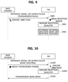
- FIG. 9 is a sequence chart illustrating a beam management method according to a detailed scheme #1 in a communication system supporting V2X communications.
- a base station may be the base station shown in FIG. 8
- a PM may be one of the PMs shown in FIG. 8 .
- the base station may be configured to transmit a reference signal or an SS/PBCH block using the transmission beam indicated by the beam configuration information of the step S 806 (S 900 ).
- the reference signal or the SS/PBCH block may be repeatedly transmitted.
- the PM may be configured to receive the reference signal or the SS/PBCH block in a beam sweeping manner.
- the PM may be configured to receive the reference signal or the SS/PBCH block in each of a plurality of receiving directions by adjusting a receiving direction thereof, and measure qualities (e.g., received signal strength) of the received reference signals or SS/PBCH blocks (S 901 ).
- the PM may be configured to determine a beam reception range (e.g., a vertical range and/or a horizontal range) based on the receiving direction indicated by the beam configuration information of the step S 806 , and may be configured to receive the reference signal and/or the SS/PBCH block by adjusting a receiving direction thereof within the beam reception range.
- a beam reception range e.g., a vertical range and/or a horizontal range
- the PM may be configured to receive the reference signal or the SS/PBCH block by adjusting a receiving direction thereof within the beam reception range indicated by the beam configuration information of the step S 806 .
- the PM may be configured to receive the reference signal or the SS/PBCH block in a plurality of receiving directions.
- the PM may be configured to determine a receiving direction in which a reference signal or the SS/PBCH block having the best quality is received as a final receiving direction (e.g., reception beam) (S 902 ).
- the PM may be configured to inform or output a notification to the base station of the receiving direction (e.g., reception beam) determined in the step S 902 .
- the transmission beam and reception beam may be configured.
- the transmission beam may be the transmission beam indicated by the beam configuration information of the step S 806
- the reception beam may be refined based on the reception beam indicated by the beam configuration information of the step S 806 .
- FIG. 10 is a sequence chart illustrating a beam management method according to a detailed scheme #2 in a communication system supporting V2X communications.
- a base station may be the base station shown in FIG. 8
- a PM may be one of the PMs shown in FIG. 8 .
- the base station may be configured to transmit the reference signal or the SS/PBCH block in a beam sweeping manner (S 1000 ).
- the base station may be configured to determine a beam transmission range based on the transmission beam indicated by the beam configuration information of the step S 806 , and transmit the reference signal or the SS/PBCH block by performing beam sweeping within the beam transmission range.
- the base station may be configured to transmit the reference signal or the SS/PBCH block by performing beam sweeping within the beam transmission range indicated by the beam configuration information of the step S 806 .
- the PM may be configured to receive the reference signal or the SS/PBCH block in the receiving direction indicated by the beam configuration information of the step S 806 , and measure the quality of the received reference signal or the SS/PBCH block (S 1001 ).
- the transmission beam or the beam transmission range indicated by the beam configuration information may be considered.
- the PM may be configured to receive the reference signal or the SS/PBCH block via a plurality of beams belonging to the beam transmission range.
- the PM may be configured to transmit, to the base station, information that indicates an index of a beam (e.g., transmission beam) on which a reference signal or the SS/PBCH block having the best quality is transmitted (S 1002 ).
- a beam e.g., transmission beam
- the transmission beam and reception beam may be configured.
- the transmission beam may be refined based on the transmission beam indicated by the beam configuration information of the step S 806
- the reception beam may be the reception beam indicated by the beam configuration information of the step S 806 .
- FIG. 11 is a sequence chart illustrating a beam management method according to a detailed scheme #3 in a communication system supporting V2X communications.
- a base station may be the base station shown in FIG. 8
- a PM may be one of the PMs shown in FIG. 8 .
- the base station may be configured to transmit the reference signal or the SS/PBCH block in a beam sweeping manner (S 1100 ).
- the base station may be configured to determine a beam transmission range based on the transmission beam indicated by the beam configuration information of the step S 806 , and transmit the reference signal or the SS/PBCH block by performing beam sweeping within the beam transmission range.
- the base station may be configured to transmit the reference signal or the SS/PBCH block by performing beam sweeping within the beam transmission range indicated by the beam configuration information of the step S 806 .
- the PM may be configured to receive the reference signal or the SS/PBCH block in the receiving direction indicated by the beam configuration information of the step S 806 , and measure the quality of the received reference signal or the SS/PBCH block (S 1101 ). Additionally, the PM may be configured to transmit, to the base station, information that indicates an index of a beam (e.g., transmission beam) on which a reference signal or the SS/PBCH block having the best quality is transmitted (S 1102 ). The base station may be configured to transmit the reference signal or the SS/PBCH block using the transmission beam indicated by the information received from the PM (S 1103 ). In the step S 1103 , the reference signal or the SS/PBCH block may be repeatedly transmitted.
- a beam e.g., transmission beam
- the PM may be configured to receive the reference signal or the SS/PBCH block in a beam sweeping manner.
- the PM may be configured to receive the reference signal or the SS/PBCH block in each of a plurality of receiving directions by adjusting a receiving direction thereof, and measure qualities (e.g., received signal strength) of the received reference signals or SS/PBCH blocks (S 1104 ).
- the PM may be configured to determine a beam reception range (e.g., a vertical range and/or a horizontal range) based on the receiving direction indicated by the beam configuration information of the step S 806 , and receive the reference signal and/or the SS/PBCH block by adjusting a receiving direction thereof within the beam reception range.
- the PM may be configured to receive the reference signal or the SS/PBCH block by adjusting a receiving direction thereof within the beam reception range indicated by the beam configuration information of the step S 806 .
- the PM may be configured to receive the reference signal or the SS/PBCH block in a plurality of receiving directions.
- the PM may be configured to determine a receiving direction in which the reference signal or the SS/PBCH block having the best quality is received as a final receiving direction (e.g., reception beam) (S 1105 ).
- the PM may be configured to inform or output a notification to the base station of the receiving direction (e.g., reception beam) determined in the step S 1105 .
- the pair of transmission beam and reception beam may be configured.
- the transmission beam may be refined based on the transmission beam indicated by the beam configuration information of the step S 806
- the reception beam may be refined based on the reception beam indicated by the beam configuration information of the step S 806 .
- the scheme #1 may be more effective than the scheme #2.
- the scheme #2 may be more effective than the scheme #1.
- FIG. 12 is a sequence chart illustrating a second exemplary embodiment of a beam management method in a communication system supporting V2X communications.
- a communication system may include a base station, a PL, a first PM, a second PM, and a third PM.
- the base station may be the base station 700 shown in FIG. 7
- the PL may be the PL 711 shown in FIG. 7 .
- the first PM may be the PM 712 shown in FIG. 7
- the second PM may be the PM 713 shown in FIG. 7
- the third PM may be the PM 714 shown in FIG. 7 . 714 .
- the beam management method shown in FIG. 12 may be used to configure beams between the vehicles participating in a platooning
- the beam management method shown in FIG. 8 may be used to configure beams between the base station and each vehicle participating in the platooning.
- a beam management method shown in FIG. 12 e.g., beam configuration procedure between the PL and each PM
- FIG. 12 e.g., beam configuration procedure between the PL and each PM
- the PL may be configured to transmit a reference signal (e.g., CSI-RS) in a beam sweeping manner (S 1200 ).
- the reference signal may be transmitted in a beam sweeping manner within a specific range behind the PL. In other words, narrow beam sweeping may be performed instead of omnidirectional beam sweeping.
- the first PM may be configured to receive the reference signal from the PL, and measure a quality (e.g., received signal strength) of the received reference signal (S 1201 ).
- the first PM may be configured to transmit information indicating an index of a beam (e.g., transmission beam index) on which a reference signal having the best quality is transmitted (S 1202 ).
- the PL may be configured to transmit the reference signal using a transmission beam indicated by the information received from the first PM (S 1203 ). In the step S 1203 , the reference signal may be repeatedly transmitted.
- the first PM may be configured to receive the reference signal in a beam sweeping manner within a specific range in front of the first PM.
- the first PM may be configured to receive the reference signal in a plurality of receiving directions by adjusting a receiving direction thereof within the specific range, and measure qualities (e.g., received signal strengths) of the received reference signals (S 1204 ).
- the first PM may be configured to determine a receiving direction in which a reference signal having the best quality is received as a final receiving direction (e.g., reception beam) (S 1205 ).
- the first PM may be configured to inform or output/transmit a notification to the PL of the receiving direction (e.g., reception beam) determined in the step S 1205 .
- the transmission beam and reception beam may be configured.
- the PL may be configured to transmit beam configuration information to the second and third PMs participating in the platooning (S 1206 ).
- the beam configuration information may include one or more among the information elements defined in Table 3.
- the beam configuration information may be transmitted via a MAC CE and/or SCI.
- the base station may be configured to transmit the beam configuration information to the second and third PMs participating in the platooning.
- the beam configuration information may be transmitted via system information, an RRC message, a MAC CE, and/or DCI.
- the beam configuration information may be transmitted in a broadcast scheme, a groupcast scheme, or a unicast scheme.
- the beam configuration information may be transmitted to the second and third PMs via the 4G communication system or the 5G communication system.
- the beam configuration information may be transmitted in a sidelink communication scheme or a single cell point-to-multipoint (SC-PTM) scheme.
- the second PM may be configured to receive the beam configuration information from the PL or the base station, and may configure a pair of transmission beam and reception beam between the second PM and the PL using the beam configuration information (S 1207 ).
- the third PM may be configured to receive the beam configuration information from the PL or the base station, and configure a pair of transmission beam and reception beam between the third PM and the PL using the beam configuration information (S 1208 ).
- Each of the steps S 1207 and S 1208 may be performed in at least one of two schemes.
- Each of the second and third PMs may be configured to perform communications using the transmission beam and reception beam indicated by the beam configuration information received from the PL or the base station when at least one of the conditions defined in Table 4 is satisfied. In other words, a separate procedure for configuring a pair of transmission beam and reception beam for each PM may not be performed.
- the transmission beam and reception beam between the PL and the second PM may be configured to the transmission beam and reception beam indicated by the beam configuration information obtained in the step S 1206 .
- the transmission beam and reception beam between the PL and the third PM may be configured to the transmission beam and reception beam indicated by the beam configuration information obtained in the step S 1206 .
- the transmission beam and reception beam between the base station and the PM may be configured based on the scheme #2 instead of the scheme #1.
- the transmission beam and reception beam between the base station and the PM may be configured based on the scheme #2.
- the thresholds of Table 4 used to determine whether to perform the scheme #2 may be different from the thresholds of Table 4 used to determine whether to perform the scheme #1.
- the link quality threshold for the scheme #2 may be lower than the link quality threshold for the scheme #1.
- the speed threshold for the scheme #2 may be greater than the speed threshold for the scheme #1.
- the scheme #2 may be classified into a detailed scheme #1, a detailed scheme #2, and a detailed scheme #3.
- the transmission beam between the base station and the PM may be fixed to the transmission beam indicated by the beam configuration information, and the reception beam between the base station and the PM may be refined.
- the detailed scheme #1 may be performed based on the exemplary embodiment shown in FIG. 9 .
- the operation of the base station in FIG. 9 may be assumed to be an operation of the PL
- the operation of the PM in FIG. 9 may be assumed to be an operation of the second PM or the third PM.
- the reception beam between the base station and the PM may be fixed to the reception beam indicated by the beam configuration information, and the transmission beam between the base station and the PM may be refined.
- the detailed scheme #2 may be performed based on the exemplary embodiment shown in FIG. 10 .
- the operation of the base station in FIG. 10 may be assumed to be an operation of the PL
- the operation of the PM in FIG. 10 may be assumed to be an operation of the second PM or the third PM.
- the transmission beam and the reception beam between the base station and the PM may be refined based on the beam configuration information.
- the detailed scheme #3 may be performed based on the exemplary embodiment shown in FIG. 11 .
- the operation of the base station in FIG. 11 may be assumed to be an operation of the PL
- the operation of the PM in FIG. 11 may be assumed to be an operation of the second PM or the third PM.
- sidelink communications may be performed between the PMs, and the sidelink communications may be performed in a beamforming manner.
- the PMs participating in the platooning may be connected in a daisy chain scheme.
- a sidelink may be established between the first PM and the second PM, and a sidelink may be established between the second PM and the third PM.
- the sidelinks established between the PMs may be used to transmit a substantial amount of data at high speed. Additionally, the sidelinks established between the PMs may be used to transmit data that is not delay sensitive.
- the sidelink between the first PM and the second PM may be configured using the beam configuration information determined through the steps S 1200 to S 1205 .
- the sidelink between the first PM and the second PM may be configured according to the scheme #1 or the scheme #2 (e.g., detailed scheme #1, #2, or #3) using the beam configuration information.
- the sidelink between the second PM and the third PM may be configured using the beam configuration information determined through the steps S 1200 to S 1205 .
- the sidelink between the second PM and the third PM may be configured according to the scheme #1 or the scheme #2 (e.g., detailed scheme #1, #2, or #3) using the beam configuration information.
- the beam configuration procedure between the PMs may be performed after the beam management method shown in FIG. 12 (e.g., the beam configuration procedure between the PL and each PM) is performed.
- the exemplary embodiments of the present disclosure may be implemented as program instructions executable by a variety of computers and recorded on a non-transitory computer readable medium.
- the non-transitory computer readable medium may include a program instruction, a data file, a data structure, or a combination thereof.
- the program instructions recorded on the non-transitory computer readable medium may be designed and configured specifically for the present disclosure or may be publicly known and available to those who are skilled in the field of computer software.
- Examples of the non-transitory computer readable medium may include a hardware device such as ROM, RAM, and flash memory, which are specifically configured to store and execute the program instructions.
- Examples of the program instructions include machine codes made by, for example, a compiler, as well as high-level language codes executable by a computer, using an interpreter.
- the above exemplary hardware device may be configured to operate as at least one software module to perform the exemplary embodiments of the present disclosure, and vice versa.
Abstract
Description
| TABLE 1 | ||
| Sidelink | ||
| Communication | ||
| Scenario | Position of |
Position of UE 236 |
| A | Out of coverage of base | Out of coverage of |
| station | ||
| 210 | station 210 | |
| B | In coverage of base | Out of coverage of |
| station | ||
| 210 | station 210 | |
| C | In coverage of base | In coverage of |
| station | ||
| 210 | station 210 | |
| D | In coverage of base | In coverage of |
| station | ||
| 210 | base station | |
| TABLE 2 | |
| | |
| TM | Description |
| 1 | Transmission using resources scheduled by |
| 2 | UE autonomous transmission without scheduling of |
| 3 | Transmission using resources scheduled by base station in |
| V2X communications | |
| 4 | UE autonomous transmission without scheduling of base station |
| in V2X communications | |
| TABLE 3 | |
| Information element | Description |
| Transmission beam | Transmission beam index of the base station, which |
| index | is determined in the steps S800 to S802 |
| Receiving direction | Receiving direction of the PL, which is determined |
| (e.g., reception | in the step S805 |
| beam index) | |
| Beam transmission | Range within which a plurality of beams are |
| range | transmitted |
| Beam reception | Range within which a plurality of receiving |
| range | directions are present |
| Cell ID | Identifier (ID) of a cell to which the PL belongs |
| (e.g., physical layer ID) | |
| Position information | Information on a position of the PL (e.g., the |
| position of the PL, which is obtained by GPS). | |
| TABLE 4 | ||
| | Description | |
| 1 | When a link quality between PM or PL or a link quality | |
| between PM and base station is equal to or greater than | ||
| a threshold (i.e., link quality threshold) | ||
| 2 | When a speed of PL or PM is equal to or less than a | |
| threshold (i.e., speed threshold) | ||
| 3 | When an ID of a cell to which PM belongs is the same as | |
| an ID of a cell to which PL belongs | ||
| TABLE 5 | ||
| | Description | |
| 1 | When vehicles participating in platooning have the same or | |
| similar antenna configurations (e.g., when types of the | ||
| vehicles participating in platooning are the same) | ||
| 2 | When a distance between PL and each PM is relatively short | |
| 3 | When a size of a cell to which vehicles participating in | |
| platooning belong is larger than a length of the platooning | ||
| 4 | When a link between a base station and each PM has a line- | |
| of-sight (LOS) property | ||
| 5 | When a distance between a base station and each PM is equal | |
| to or greater than a threshold | ||
| 6 | When vehicles participating in platooning travel on a straight | |
| road | ||
| TABLE 6 | ||
| | Description | |
| 1 | When vehicles participating in platooning have different | |
| antenna configurations (e.g., when types of the vehicles | ||
| participating in platooning are different) | ||
| 2 | When a distance between PL and each PM is relatively long | |
| 3 | When a size of a cell to which vehicles participating in | |
| platooning belong is equal to or less than a length of the | ||
| platooning | ||
| 4 | When a link between a base station and each PM has a non- | |
| LOS property | ||
| 5 | When a distance between a base station and each PM is less | |
| than a threshold | ||
| 6 | When vehicles participating in platooning travel on a curve | |
| road | ||
Claims (20)
Priority Applications (1)
| Application Number | Priority Date | Filing Date | Title |
|---|---|---|---|
| US16/669,100 US11234145B2 (en) | 2018-11-01 | 2019-10-30 | Method and apparatus for beam management in communication system supporting vehicle-to-everything communication |
Applications Claiming Priority (4)
| Application Number | Priority Date | Filing Date | Title |
|---|---|---|---|
| US201862754236P | 2018-11-01 | 2018-11-01 | |
| KR10-2019-0131675 | 2019-10-22 | ||
| KR1020190131675A KR20200050377A (en) | 2018-11-01 | 2019-10-22 | Method and apparatus for beam management in communication system supporting vehicle to everything |
| US16/669,100 US11234145B2 (en) | 2018-11-01 | 2019-10-30 | Method and apparatus for beam management in communication system supporting vehicle-to-everything communication |
Publications (2)
| Publication Number | Publication Date |
|---|---|
| US20200145855A1 US20200145855A1 (en) | 2020-05-07 |
| US11234145B2 true US11234145B2 (en) | 2022-01-25 |
Family
ID=68424814
Family Applications (1)
| Application Number | Title | Priority Date | Filing Date |
|---|---|---|---|
| US16/669,100 Active 2039-11-01 US11234145B2 (en) | 2018-11-01 | 2019-10-30 | Method and apparatus for beam management in communication system supporting vehicle-to-everything communication |
Country Status (2)
| Country | Link |
|---|---|
| US (1) | US11234145B2 (en) |
| EP (2) | EP3648367B1 (en) |
Cited By (1)
| Publication number | Priority date | Publication date | Assignee | Title |
|---|---|---|---|---|
| US11503491B2 (en) * | 2019-11-07 | 2022-11-15 | Lg Electronics Inc. | Cancelling SL CSI reporting in a wireless communication system |
Families Citing this family (4)
| Publication number | Priority date | Publication date | Assignee | Title |
|---|---|---|---|---|
| KR20210020460A (en) * | 2019-08-14 | 2021-02-24 | 삼성전자주식회사 | Method and apparatus for harq feedback in a wireless communication system |
| US10998945B1 (en) * | 2020-01-10 | 2021-05-04 | Huawei Technologies Co., Ltd. | Beam acquisition methods and communication devices |
| US11228378B2 (en) * | 2020-04-03 | 2022-01-18 | Rohde & Schwarz Gmbh & Co. Kg | Method and system for estimating a transmission direction of a transmitter |
| US20230224725A1 (en) * | 2020-07-02 | 2023-07-13 | Qualcomm Incorporated | Managing beam coverage area representations in wireless communications systems |
Citations (5)
| Publication number | Priority date | Publication date | Assignee | Title |
|---|---|---|---|---|
| US20170289864A1 (en) | 2016-04-01 | 2017-10-05 | Futurewei Technologies, Inc. | Methods for Data Communication to a Platoon of Connected Vehicles |
| US9882689B2 (en) * | 2012-10-18 | 2018-01-30 | Samsung Electronics Co., Ltd. | Apparatus and method for base station cooperative communication in wireless communication system |
| WO2018064179A1 (en) | 2016-09-30 | 2018-04-05 | Intel Corporation | V2x services in next generation cellular networks |
| US20200145079A1 (en) * | 2016-05-11 | 2020-05-07 | Idac Holdings, Inc. | Systems and methods for beamformed uplink transmission |
| US20200404593A1 (en) * | 2017-11-17 | 2020-12-24 | Zte Corporation | Power control method, ue, base station, parameter configuration method and control method |
-
2019
- 2019-10-30 US US16/669,100 patent/US11234145B2/en active Active
- 2019-10-31 EP EP19206517.5A patent/EP3648367B1/en active Active
- 2019-10-31 EP EP21168562.3A patent/EP3869705B1/en active Active
Patent Citations (5)
| Publication number | Priority date | Publication date | Assignee | Title |
|---|---|---|---|---|
| US9882689B2 (en) * | 2012-10-18 | 2018-01-30 | Samsung Electronics Co., Ltd. | Apparatus and method for base station cooperative communication in wireless communication system |
| US20170289864A1 (en) | 2016-04-01 | 2017-10-05 | Futurewei Technologies, Inc. | Methods for Data Communication to a Platoon of Connected Vehicles |
| US20200145079A1 (en) * | 2016-05-11 | 2020-05-07 | Idac Holdings, Inc. | Systems and methods for beamformed uplink transmission |
| WO2018064179A1 (en) | 2016-09-30 | 2018-04-05 | Intel Corporation | V2x services in next generation cellular networks |
| US20200404593A1 (en) * | 2017-11-17 | 2020-12-24 | Zte Corporation | Power control method, ue, base station, parameter configuration method and control method |
Cited By (2)
| Publication number | Priority date | Publication date | Assignee | Title |
|---|---|---|---|---|
| US11503491B2 (en) * | 2019-11-07 | 2022-11-15 | Lg Electronics Inc. | Cancelling SL CSI reporting in a wireless communication system |
| US11722923B2 (en) | 2019-11-07 | 2023-08-08 | Lg Electronics Inc. | Cancelling SL CSI reporting in a wireless communication system |
Also Published As
| Publication number | Publication date |
|---|---|
| EP3869705B1 (en) | 2022-12-21 |
| EP3869705A1 (en) | 2021-08-25 |
| CN111148065A (en) | 2020-05-12 |
| EP3648367A1 (en) | 2020-05-06 |
| US20200145855A1 (en) | 2020-05-07 |
| EP3648367B1 (en) | 2021-06-09 |
Similar Documents
| Publication | Publication Date | Title |
|---|---|---|
| US11778578B2 (en) | Method for sidelink communication based on beamforming in communication system | |
| US11576166B2 (en) | Method for sidelink communication in consideration of resource occupancy state in communication system and apparatus for the same | |
| US11889572B2 (en) | Method for transmitting and receiving control information including configuration information for transmission and reception in communication system supporting vehicle-to-everything communication and apparatus for the same | |
| US20220191658A1 (en) | Method and apparatus for load distribution using a plurality of carriers in communication system supporting vehicle-to-everything communication | |
| US11234145B2 (en) | Method and apparatus for beam management in communication system supporting vehicle-to-everything communication | |
| US11310772B2 (en) | Method and apparatus for configuring bandwidth part in sidelink communication | |
| US11503604B2 (en) | Method for configuring sidelink resources based on user equipment speed in communication system and apparatus for the same | |
| US11855929B2 (en) | Method and apparatus for reconfiguring bandwidth part for groupcast in sidelink communication | |
| US11877216B2 (en) | Method and apparatus for selecting carrier in communication system supporting vehicle to everything communication | |
| US10827325B2 (en) | Method for transmitting and receiving data using heterogeneous radio access technology in communication system supporting vehicle-to-everything communication and apparatus for the same | |
| US11277876B2 (en) | Method and apparatus for low latency communication in vehicle-to-everything communication system | |
| US20220039076A1 (en) | Method and device for sidelink groupcast communication | |
| US20210068189A1 (en) | Method and apparatus for radio link management in sidelink communication | |
| CN113366902A (en) | Method and apparatus for sidelink multicast communication | |
| KR20200050377A (en) | Method and apparatus for beam management in communication system supporting vehicle to everything | |
| CN111148065B (en) | Method and apparatus for beam management in a communication system supporting vehicle-to-all communication |
Legal Events
| Date | Code | Title | Description |
|---|---|---|---|
| AS | Assignment |
Owner name: INDUSTRY-ACADEMIC COOPERATION FOUNDATION, DANKOOK UNIVERSITY, KOREA, REPUBLIC OF Free format text: ASSIGNMENT OF ASSIGNORS INTEREST;ASSIGNORS:HAHN, GENE BECK;CHOI, SU HAN;REEL/FRAME:050868/0367 Effective date: 20191018 Owner name: KIA MOTORS CORPORATION, KOREA, REPUBLIC OF Free format text: ASSIGNMENT OF ASSIGNORS INTEREST;ASSIGNORS:HAHN, GENE BECK;CHOI, SU HAN;REEL/FRAME:050868/0367 Effective date: 20191018 Owner name: HYUNDAI MOTOR COMPANY, KOREA, REPUBLIC OF Free format text: ASSIGNMENT OF ASSIGNORS INTEREST;ASSIGNORS:HAHN, GENE BECK;CHOI, SU HAN;REEL/FRAME:050868/0367 Effective date: 20191018 |
|
| FEPP | Fee payment procedure |
Free format text: ENTITY STATUS SET TO UNDISCOUNTED (ORIGINAL EVENT CODE: BIG.); ENTITY STATUS OF PATENT OWNER: LARGE ENTITY |
|
| AS | Assignment |
Owner name: KIA MOTORS CORPORATION, KOREA, REPUBLIC OF Free format text: ASSIGNMENT OF ASSIGNORS INTEREST;ASSIGNOR:INDUSTRY-ACADEMIC COOPERATION FOUNDATION;REEL/FRAME:051819/0647 Effective date: 20200106 Owner name: HYUNDAI MOTOR COMPANY, KOREA, REPUBLIC OF Free format text: ASSIGNMENT OF ASSIGNORS INTEREST;ASSIGNOR:INDUSTRY-ACADEMIC COOPERATION FOUNDATION;REEL/FRAME:051819/0647 Effective date: 20200106 |
|
| STPP | Information on status: patent application and granting procedure in general |
Free format text: NON FINAL ACTION MAILED |
|
| STPP | Information on status: patent application and granting procedure in general |
Free format text: RESPONSE TO NON-FINAL OFFICE ACTION ENTERED AND FORWARDED TO EXAMINER |
|
| STPP | Information on status: patent application and granting procedure in general |
Free format text: EX PARTE QUAYLE ACTION MAILED |
|
| STPP | Information on status: patent application and granting procedure in general |
Free format text: RESPONSE TO EX PARTE QUAYLE ACTION ENTERED AND FORWARDED TO EXAMINER |
|
| STPP | Information on status: patent application and granting procedure in general |
Free format text: NOTICE OF ALLOWANCE MAILED -- APPLICATION RECEIVED IN OFFICE OF PUBLICATIONS |
|
| STPP | Information on status: patent application and granting procedure in general |
Free format text: PUBLICATIONS -- ISSUE FEE PAYMENT VERIFIED |
|
| STCF | Information on status: patent grant |
Free format text: PATENTED CASE |