EP3481667B1 - Verstelleinrichtung für die längsverstellung eines fahrzeugsitzes - Google Patents
Verstelleinrichtung für die längsverstellung eines fahrzeugsitzes Download PDFInfo
- Publication number
- EP3481667B1 EP3481667B1 EP17811585.3A EP17811585A EP3481667B1 EP 3481667 B1 EP3481667 B1 EP 3481667B1 EP 17811585 A EP17811585 A EP 17811585A EP 3481667 B1 EP3481667 B1 EP 3481667B1
- Authority
- EP
- European Patent Office
- Prior art keywords
- seat
- adjusting
- spindle
- rail
- adjustment
- Prior art date
- Legal status (The legal status is an assumption and is not a legal conclusion. Google has not performed a legal analysis and makes no representation as to the accuracy of the status listed.)
- Active
Links
Images


Classifications
-
- B—PERFORMING OPERATIONS; TRANSPORTING
- B60—VEHICLES IN GENERAL
- B60N—SEATS SPECIALLY ADAPTED FOR VEHICLES; VEHICLE PASSENGER ACCOMMODATION NOT OTHERWISE PROVIDED FOR
- B60N2/00—Seats specially adapted for vehicles; Arrangement or mounting of seats in vehicles
- B60N2/02—Seats specially adapted for vehicles; Arrangement or mounting of seats in vehicles the seat or part thereof being movable, e.g. adjustable
- B60N2/04—Seats specially adapted for vehicles; Arrangement or mounting of seats in vehicles the seat or part thereof being movable, e.g. adjustable the whole seat being movable
- B60N2/06—Seats specially adapted for vehicles; Arrangement or mounting of seats in vehicles the seat or part thereof being movable, e.g. adjustable the whole seat being movable slidable
- B60N2/07—Slide construction
- B60N2/0735—Position and orientation of the slide as a whole
- B60N2/0747—Position and orientation of the slide as a whole the opening of the cross section being oriented in a direction different from the vertical, e.g. transversal
-
- B—PERFORMING OPERATIONS; TRANSPORTING
- B60—VEHICLES IN GENERAL
- B60N—SEATS SPECIALLY ADAPTED FOR VEHICLES; VEHICLE PASSENGER ACCOMMODATION NOT OTHERWISE PROVIDED FOR
- B60N2/00—Seats specially adapted for vehicles; Arrangement or mounting of seats in vehicles
- B60N2/02—Seats specially adapted for vehicles; Arrangement or mounting of seats in vehicles the seat or part thereof being movable, e.g. adjustable
- B60N2/04—Seats specially adapted for vehicles; Arrangement or mounting of seats in vehicles the seat or part thereof being movable, e.g. adjustable the whole seat being movable
- B60N2/06—Seats specially adapted for vehicles; Arrangement or mounting of seats in vehicles the seat or part thereof being movable, e.g. adjustable the whole seat being movable slidable
- B60N2/07—Slide construction
-
- B—PERFORMING OPERATIONS; TRANSPORTING
- B60—VEHICLES IN GENERAL
- B60N—SEATS SPECIALLY ADAPTED FOR VEHICLES; VEHICLE PASSENGER ACCOMMODATION NOT OTHERWISE PROVIDED FOR
- B60N2/00—Seats specially adapted for vehicles; Arrangement or mounting of seats in vehicles
- B60N2/005—Arrangement or mounting of seats in vehicles, e.g. dismountable auxiliary seats
-
- B—PERFORMING OPERATIONS; TRANSPORTING
- B60—VEHICLES IN GENERAL
- B60N—SEATS SPECIALLY ADAPTED FOR VEHICLES; VEHICLE PASSENGER ACCOMMODATION NOT OTHERWISE PROVIDED FOR
- B60N2/00—Seats specially adapted for vehicles; Arrangement or mounting of seats in vehicles
- B60N2/005—Arrangement or mounting of seats in vehicles, e.g. dismountable auxiliary seats
- B60N2/015—Attaching seats directly to vehicle chassis
- B60N2/01508—Attaching seats directly to vehicle chassis using quick release attachments
- B60N2/01516—Attaching seats directly to vehicle chassis using quick release attachments with locking mechanisms
- B60N2/01558—Attaching seats directly to vehicle chassis using quick release attachments with locking mechanisms with key and slot
- B60N2/01575—Attaching seats directly to vehicle chassis using quick release attachments with locking mechanisms with key and slot key sliding inside the vehicle floor or rail
-
- B—PERFORMING OPERATIONS; TRANSPORTING
- B60—VEHICLES IN GENERAL
- B60N—SEATS SPECIALLY ADAPTED FOR VEHICLES; VEHICLE PASSENGER ACCOMMODATION NOT OTHERWISE PROVIDED FOR
- B60N2/00—Seats specially adapted for vehicles; Arrangement or mounting of seats in vehicles
- B60N2/005—Arrangement or mounting of seats in vehicles, e.g. dismountable auxiliary seats
- B60N2/015—Attaching seats directly to vehicle chassis
- B60N2/01508—Attaching seats directly to vehicle chassis using quick release attachments
- B60N2/01591—Attaching seats directly to vehicle chassis using quick release attachments with wheels coupled to the seat
-
- B—PERFORMING OPERATIONS; TRANSPORTING
- B60—VEHICLES IN GENERAL
- B60N—SEATS SPECIALLY ADAPTED FOR VEHICLES; VEHICLE PASSENGER ACCOMMODATION NOT OTHERWISE PROVIDED FOR
- B60N2/00—Seats specially adapted for vehicles; Arrangement or mounting of seats in vehicles
- B60N2/02—Seats specially adapted for vehicles; Arrangement or mounting of seats in vehicles the seat or part thereof being movable, e.g. adjustable
-
- B—PERFORMING OPERATIONS; TRANSPORTING
- B60—VEHICLES IN GENERAL
- B60N—SEATS SPECIALLY ADAPTED FOR VEHICLES; VEHICLE PASSENGER ACCOMMODATION NOT OTHERWISE PROVIDED FOR
- B60N2/00—Seats specially adapted for vehicles; Arrangement or mounting of seats in vehicles
- B60N2/02—Seats specially adapted for vehicles; Arrangement or mounting of seats in vehicles the seat or part thereof being movable, e.g. adjustable
- B60N2/0224—Non-manual adjustments, e.g. with electrical operation
-
- B—PERFORMING OPERATIONS; TRANSPORTING
- B60—VEHICLES IN GENERAL
- B60N—SEATS SPECIALLY ADAPTED FOR VEHICLES; VEHICLE PASSENGER ACCOMMODATION NOT OTHERWISE PROVIDED FOR
- B60N2/00—Seats specially adapted for vehicles; Arrangement or mounting of seats in vehicles
- B60N2/02—Seats specially adapted for vehicles; Arrangement or mounting of seats in vehicles the seat or part thereof being movable, e.g. adjustable
- B60N2/0224—Non-manual adjustments, e.g. with electrical operation
- B60N2/02246—Electric motors therefor
-
- B—PERFORMING OPERATIONS; TRANSPORTING
- B60—VEHICLES IN GENERAL
- B60N—SEATS SPECIALLY ADAPTED FOR VEHICLES; VEHICLE PASSENGER ACCOMMODATION NOT OTHERWISE PROVIDED FOR
- B60N2/00—Seats specially adapted for vehicles; Arrangement or mounting of seats in vehicles
- B60N2/02—Seats specially adapted for vehicles; Arrangement or mounting of seats in vehicles the seat or part thereof being movable, e.g. adjustable
- B60N2/04—Seats specially adapted for vehicles; Arrangement or mounting of seats in vehicles the seat or part thereof being movable, e.g. adjustable the whole seat being movable
- B60N2/06—Seats specially adapted for vehicles; Arrangement or mounting of seats in vehicles the seat or part thereof being movable, e.g. adjustable the whole seat being movable slidable
-
- B—PERFORMING OPERATIONS; TRANSPORTING
- B60—VEHICLES IN GENERAL
- B60N—SEATS SPECIALLY ADAPTED FOR VEHICLES; VEHICLE PASSENGER ACCOMMODATION NOT OTHERWISE PROVIDED FOR
- B60N2/00—Seats specially adapted for vehicles; Arrangement or mounting of seats in vehicles
- B60N2/02—Seats specially adapted for vehicles; Arrangement or mounting of seats in vehicles the seat or part thereof being movable, e.g. adjustable
- B60N2/04—Seats specially adapted for vehicles; Arrangement or mounting of seats in vehicles the seat or part thereof being movable, e.g. adjustable the whole seat being movable
- B60N2/06—Seats specially adapted for vehicles; Arrangement or mounting of seats in vehicles the seat or part thereof being movable, e.g. adjustable the whole seat being movable slidable
- B60N2/067—Seats specially adapted for vehicles; Arrangement or mounting of seats in vehicles the seat or part thereof being movable, e.g. adjustable the whole seat being movable slidable by linear actuators, e.g. linear screw mechanisms
-
- B—PERFORMING OPERATIONS; TRANSPORTING
- B60—VEHICLES IN GENERAL
- B60N—SEATS SPECIALLY ADAPTED FOR VEHICLES; VEHICLE PASSENGER ACCOMMODATION NOT OTHERWISE PROVIDED FOR
- B60N2/00—Seats specially adapted for vehicles; Arrangement or mounting of seats in vehicles
- B60N2/02—Seats specially adapted for vehicles; Arrangement or mounting of seats in vehicles the seat or part thereof being movable, e.g. adjustable
- B60N2/04—Seats specially adapted for vehicles; Arrangement or mounting of seats in vehicles the seat or part thereof being movable, e.g. adjustable the whole seat being movable
- B60N2/12—Seats specially adapted for vehicles; Arrangement or mounting of seats in vehicles the seat or part thereof being movable, e.g. adjustable the whole seat being movable slidable and tiltable
-
- B—PERFORMING OPERATIONS; TRANSPORTING
- B60—VEHICLES IN GENERAL
- B60N—SEATS SPECIALLY ADAPTED FOR VEHICLES; VEHICLE PASSENGER ACCOMMODATION NOT OTHERWISE PROVIDED FOR
- B60N2/00—Seats specially adapted for vehicles; Arrangement or mounting of seats in vehicles
- B60N2/02—Seats specially adapted for vehicles; Arrangement or mounting of seats in vehicles the seat or part thereof being movable, e.g. adjustable
- B60N2/04—Seats specially adapted for vehicles; Arrangement or mounting of seats in vehicles the seat or part thereof being movable, e.g. adjustable the whole seat being movable
- B60N2/16—Seats specially adapted for vehicles; Arrangement or mounting of seats in vehicles the seat or part thereof being movable, e.g. adjustable the whole seat being movable height-adjustable
- B60N2/1635—Seats specially adapted for vehicles; Arrangement or mounting of seats in vehicles the seat or part thereof being movable, e.g. adjustable the whole seat being movable height-adjustable characterised by the drive mechanism
-
- B—PERFORMING OPERATIONS; TRANSPORTING
- B60—VEHICLES IN GENERAL
- B60N—SEATS SPECIALLY ADAPTED FOR VEHICLES; VEHICLE PASSENGER ACCOMMODATION NOT OTHERWISE PROVIDED FOR
- B60N2/00—Seats specially adapted for vehicles; Arrangement or mounting of seats in vehicles
- B60N2/02—Seats specially adapted for vehicles; Arrangement or mounting of seats in vehicles the seat or part thereof being movable, e.g. adjustable
- B60N2/04—Seats specially adapted for vehicles; Arrangement or mounting of seats in vehicles the seat or part thereof being movable, e.g. adjustable the whole seat being movable
- B60N2/16—Seats specially adapted for vehicles; Arrangement or mounting of seats in vehicles the seat or part thereof being movable, e.g. adjustable the whole seat being movable height-adjustable
- B60N2/1635—Seats specially adapted for vehicles; Arrangement or mounting of seats in vehicles the seat or part thereof being movable, e.g. adjustable the whole seat being movable height-adjustable characterised by the drive mechanism
- B60N2/164—Linear actuator, e.g. screw mechanism
-
- B—PERFORMING OPERATIONS; TRANSPORTING
- B60—VEHICLES IN GENERAL
- B60N—SEATS SPECIALLY ADAPTED FOR VEHICLES; VEHICLE PASSENGER ACCOMMODATION NOT OTHERWISE PROVIDED FOR
- B60N2/00—Seats specially adapted for vehicles; Arrangement or mounting of seats in vehicles
- B60N2/02—Seats specially adapted for vehicles; Arrangement or mounting of seats in vehicles the seat or part thereof being movable, e.g. adjustable
- B60N2/04—Seats specially adapted for vehicles; Arrangement or mounting of seats in vehicles the seat or part thereof being movable, e.g. adjustable the whole seat being movable
- B60N2/16—Seats specially adapted for vehicles; Arrangement or mounting of seats in vehicles the seat or part thereof being movable, e.g. adjustable the whole seat being movable height-adjustable
- B60N2/1695—Seats specially adapted for vehicles; Arrangement or mounting of seats in vehicles the seat or part thereof being movable, e.g. adjustable the whole seat being movable height-adjustable with simultaneous height and inclination adjustment
-
- B—PERFORMING OPERATIONS; TRANSPORTING
- B60—VEHICLES IN GENERAL
- B60N—SEATS SPECIALLY ADAPTED FOR VEHICLES; VEHICLE PASSENGER ACCOMMODATION NOT OTHERWISE PROVIDED FOR
- B60N2/00—Seats specially adapted for vehicles; Arrangement or mounting of seats in vehicles
- B60N2/02—Seats specially adapted for vehicles; Arrangement or mounting of seats in vehicles the seat or part thereof being movable, e.g. adjustable
- B60N2/04—Seats specially adapted for vehicles; Arrangement or mounting of seats in vehicles the seat or part thereof being movable, e.g. adjustable the whole seat being movable
- B60N2/16—Seats specially adapted for vehicles; Arrangement or mounting of seats in vehicles the seat or part thereof being movable, e.g. adjustable the whole seat being movable height-adjustable
- B60N2/18—Seats specially adapted for vehicles; Arrangement or mounting of seats in vehicles the seat or part thereof being movable, e.g. adjustable the whole seat being movable height-adjustable the front or the rear portion of the seat being adjustable, e.g. independently of each other
- B60N2/1803—Seats specially adapted for vehicles; Arrangement or mounting of seats in vehicles the seat or part thereof being movable, e.g. adjustable the whole seat being movable height-adjustable the front or the rear portion of the seat being adjustable, e.g. independently of each other with independent front and/or rear adjustment
-
- B—PERFORMING OPERATIONS; TRANSPORTING
- B60—VEHICLES IN GENERAL
- B60N—SEATS SPECIALLY ADAPTED FOR VEHICLES; VEHICLE PASSENGER ACCOMMODATION NOT OTHERWISE PROVIDED FOR
- B60N2/00—Seats specially adapted for vehicles; Arrangement or mounting of seats in vehicles
- B60N2/02—Seats specially adapted for vehicles; Arrangement or mounting of seats in vehicles the seat or part thereof being movable, e.g. adjustable
- B60N2/04—Seats specially adapted for vehicles; Arrangement or mounting of seats in vehicles the seat or part thereof being movable, e.g. adjustable the whole seat being movable
- B60N2/16—Seats specially adapted for vehicles; Arrangement or mounting of seats in vehicles the seat or part thereof being movable, e.g. adjustable the whole seat being movable height-adjustable
- B60N2/18—Seats specially adapted for vehicles; Arrangement or mounting of seats in vehicles the seat or part thereof being movable, e.g. adjustable the whole seat being movable height-adjustable the front or the rear portion of the seat being adjustable, e.g. independently of each other
- B60N2/185—Seats specially adapted for vehicles; Arrangement or mounting of seats in vehicles the seat or part thereof being movable, e.g. adjustable the whole seat being movable height-adjustable the front or the rear portion of the seat being adjustable, e.g. independently of each other characterised by the drive mechanism
-
- B—PERFORMING OPERATIONS; TRANSPORTING
- B60—VEHICLES IN GENERAL
- B60N—SEATS SPECIALLY ADAPTED FOR VEHICLES; VEHICLE PASSENGER ACCOMMODATION NOT OTHERWISE PROVIDED FOR
- B60N2/00—Seats specially adapted for vehicles; Arrangement or mounting of seats in vehicles
- B60N2/02—Seats specially adapted for vehicles; Arrangement or mounting of seats in vehicles the seat or part thereof being movable, e.g. adjustable
- B60N2/04—Seats specially adapted for vehicles; Arrangement or mounting of seats in vehicles the seat or part thereof being movable, e.g. adjustable the whole seat being movable
- B60N2/16—Seats specially adapted for vehicles; Arrangement or mounting of seats in vehicles the seat or part thereof being movable, e.g. adjustable the whole seat being movable height-adjustable
- B60N2/18—Seats specially adapted for vehicles; Arrangement or mounting of seats in vehicles the seat or part thereof being movable, e.g. adjustable the whole seat being movable height-adjustable the front or the rear portion of the seat being adjustable, e.g. independently of each other
- B60N2/185—Seats specially adapted for vehicles; Arrangement or mounting of seats in vehicles the seat or part thereof being movable, e.g. adjustable the whole seat being movable height-adjustable the front or the rear portion of the seat being adjustable, e.g. independently of each other characterised by the drive mechanism
- B60N2/1853—Linear actuator, e.g. screw mechanism
-
- B—PERFORMING OPERATIONS; TRANSPORTING
- B60—VEHICLES IN GENERAL
- B60N—SEATS SPECIALLY ADAPTED FOR VEHICLES; VEHICLE PASSENGER ACCOMMODATION NOT OTHERWISE PROVIDED FOR
- B60N2/00—Seats specially adapted for vehicles; Arrangement or mounting of seats in vehicles
- B60N2/02—Seats specially adapted for vehicles; Arrangement or mounting of seats in vehicles the seat or part thereof being movable, e.g. adjustable
- B60N2002/0204—Seats specially adapted for vehicles; Arrangement or mounting of seats in vehicles the seat or part thereof being movable, e.g. adjustable characterised by the seat or seat part turning about or moving along a non-standard, particular axis, i.e. an axis different from the axis characterising the conventional movement
- B60N2002/0212—Seats specially adapted for vehicles; Arrangement or mounting of seats in vehicles the seat or part thereof being movable, e.g. adjustable characterised by the seat or seat part turning about or moving along a non-standard, particular axis, i.e. an axis different from the axis characterising the conventional movement the seat or seat part turning about or moving along a longitudinal axis
Definitions
- the invention relates to an adjustment device for the longitudinal adjustment of a vehicle seat.
- An adjustment device customary in practice has, inter alia, a first rail provided for fastening to a vehicle floor and a second rail provided for connection to a seat underframe of the vehicle seat.
- the second rail is mounted such that it can be adjusted relative to the first rail in order to enable the vehicle seat to be adjusted longitudinally along a longitudinal direction of the seat.
- a vehicle seat usually has two pairs of first and second rails, by means of which the vehicle seat is arranged to be longitudinally displaceable on the vehicle floor.
- the adjusting device regularly has a (adjusting) spindle and a spindle nut which meshes with the spindle.
- Adjustment devices known in this regard, for example, disclose the DE 198 15 283 A1 and the WO 2005/015054 A1 ,
- the spindle drives provided here in each case with a spindle and a spindle nut meshing therewith usually have a common, for example electromotive, drive in order to adjust the frame-fixed (second) rails assigned to one longitudinal side of the seat synchronously relative to a pair of floor-mounted (first) rails with power actuation.
- the DE 10 2004 055643 A1 describes a method for seat adjustment such as height adjustment and / or inclination adjustment and / or longitudinal adjustment by means of drives as well as a seat with various adjustment functions such as height adjustment, inclination adjustment, longitudinal adjustment by means of drives, essentially consisting of a seat part with a seat surface, a backrest part with a backrest surface and from at least one frame ,
- For the seat adjustment primarily parallel adjusting movements are carried out, which bring about an adhesion-optimized and / or mass-optimized adjustment of seat elements such as a seat part with a seat surface or a backrest with a backrest surface.
- the seat provides that parallel structures, such as slide-like adjustment guides, are provided, which transfer the adjustment forces into a truss-like seat frame.
- the DE 10 2014 225 358 A1 describes a vehicle seat assembly with a backrest and a seat receptacle that is pivotally coupled to the backrest.
- An upper link is coupled between an upper portion of the backrest and a rear support.
- a front and a rear link are coupled between the seat receptacle and a floor.
- a lower end of the front link is movable on the floor between a front and a rear position, whereby the backrest is adjusted between a lying and an upright position.
- the objective of the present solution is to provide an improved adjustment device for the longitudinal adjustment, which, for example, offers additional adjustment options for the vehicle seat and / or which is an improvement in terms of durability and mountability.
- an adjustment device for the longitudinal production of a vehicle seat which, among other things, has at least one rail which is provided for specifying a longitudinal axis of the seat, along which a seat underframe of the vehicle seat is adjustable, and for mounting at least one adjustment unit of the adjustment device.
- the adjustment device comprises at least two displaceably guided adjustment units which are arranged one behind the other along the longitudinal axis of the seat and on which the seat underframe is to be fixed, for example via a rocker, in order to be adjustable along the longitudinal axis of the seat.
- the at least two adjustment units are adjustable relative to one another along the longitudinal axis of the seat and each adjustment unit is assigned its own drive for power-operated adjustment along the longitudinal axis of the seat, a common, fixed spindle being provided for the power-operated adjustment of the at least two adjustment units, with the two, each comb spindle nuts assigned to an adjusting unit.
- At least two adjustment units are thus assigned to one of the two longitudinal sides of the seat, but in this case are not rigidly coupled to one another, but rather can be adjusted relative to one another along the longitudinal axis of the seat, actuated by power.
- each adjustment unit is assigned its own drive, so that by controlling the different drives - and therefore not by mechanically decoupling the two adjustment units - a distance between the two adjustment units can be varied along the longitudinal axis of the seat.
- at least one additional adjustment possibility for the vehicle seat and in particular its seat base can be provided via the adjustment device, without additional components having to be provided for this.
- the vehicle seat is not only longitudinally adjustable, but also additionally adjustable in its orientation with respect to the vehicle floor, via the adjustment units provided relative to one another and on the right or left longitudinal side of the seat.
- the adjustment unit can have a bearing part for connection to a swing arm of the seat base frame.
- a rocker is then articulated, for example, on the bearing part of the adjustment unit and also on a component of the seat base frame, in order to enable the seat base frame to be tilted by means of the adjustment units which are adjustable relative to one another along the longitudinal axis of the seat.
- a longitudinal axis of the spindle runs essentially perpendicular to a drive axis of the drive of an adjustment unit.
- a drive shaft of an electromotive drive runs essentially perpendicular to the longitudinal axis of the spindle, with which a spindle nut meshed by the drive meshes with a rotation.
- the transmission of a drive torque provided by the drive for the adjustment of the respective adjustment unit is consequently carried out here via a correspondingly designed adjustment gear having the spindle nut.
- a (single) electronic control unit for example in the form of a control unit to be arranged on the seat base, can be provided for controlling the adjustment movements of the at least two adjustment units relative to one another.
- Such an electronic control unit is then set up, for example, to vary the distance of the at least two adjustment units arranged one behind the other relative to one another along the longitudinal axis of the seat for changing an inclination and / or a height of the seat base frame and / or an upholstery rain arranged thereon.
- the electronic control unit can thus, for example, independently control each drive of the adjustment units in order to adjust the adjustment units towards or away from one another along the longitudinal axis of the seat.
- the electronic control unit is set up to control only one of the drives of the different adjusting units arranged one behind the other along the longitudinal axis of the seat, so that the associated adjusting unit is adjusted relative to at least one fixed adjusting unit of the adjusting device along the longitudinal axis of the seat.
- Such an adjustment can be provided, for example, for adjusting an inclination of the seat surface of the vehicle seat while maintaining the adjusted longitudinal position of the seat.
- the at least two adjustment units are slidably mounted on one and the same rail.
- the use of a single, continuous spindle fixed to this rail for the at least two adjustment units is also appropriate.
- the at least two adjustment units can also be displaceably mounted on different rails in an alternative embodiment variant.
- At least one adjustment unit of the adjustment device is slidably mounted on the at least one rail via at least one support element.
- the adjusting unit thus has an additional component with the support element, which ensures the displaceable mounting on the at least one rail.
- the support element can, for example, slide against the rail and thus be designed in the manner of a slider and be displaceable along the rail.
- the at least one support element can be rotatably mounted and can perform a rotary movement for displacing the adjustment unit along the longitudinal axis of the seat.
- Such a support element thus has, for example, a roller or roller, which allows the adjustment unit to be displaced along the longitudinal axis of the seat by rolling off the rail or a component connected to it, if the adjustment unit is driven by the drive for this purpose.
- the at least one support element can in principle be supported on the rail or a component connected to it, in order to specify a defined position on the rail for the adjustment unit and to support a rattle-free adjustment of the adjustment unit along the rail.
- the at least one support element is supported on a convexly curved guide profile which is formed in one piece with the rail or which is designed as a separate component and is connected to the rail.
- a corresponding guide profile can for example be arranged running above or below the spindle.
- two guide profiles of comparable or identical design are provided on the rail in order to enable one or more (at least two) support elements to be supported in different directions.
- guide profiles offset from one another can also be provided on the rail, for example guide profiles offset from one another by 90 °.
- the spindle is supported on the at least one support element of an adjustment unit. If, for example, there is always an adjustment unit between two spindle ends of the spindle, which are fixed to the rail via a spindle holder, an undesired deflection of the spindle can be prevented or at least considerably reduced via an adjustment unit with a support element supporting the spindle.
- a spindle that is more than 1 m long and that allows a vehicle seat to be adjusted between the first and second row of seats in the vehicle without additional support points along to avoid undesired bending of the spindle the spindle axis would have to be provided. Rather, sufficient support can be achieved transversely to the longitudinal axis of the spindle via the at least one support element of the adjustment unit which can be adjusted along the spindle.
- the support element can in particular be supported above and / or below the spindle on the rail or a component connected to it, in order to dissipate transverse forces from the seat underframe into the rail and thus the vehicle floor when the vehicle seat is in the correct position the adjustment device is fixed.
- two support elements are provided on an adjustment unit, each of which enables the adjustment unit and thus the seat base frame to be connected to it to be supported on the rail or a component connected to it.
- a spindle provided for the adjustment of an adjustment unit or at least two adjustment units extends between at least two support elements of an adjustment unit. The spindle is thus supported in different directions via the at least two support elements.
- At least two pairs of two support elements arranged one behind the other along the longitudinal axis of the seat are provided on an adjustment unit, so that the spindle extends between these at least two pairs.
- the spindle is thus supported on the adjusting unit in two regions spaced apart from one another along the longitudinal axis of the seat in different - preferably opposite, spatial directions - via the support elements on the rail.
- the spindle nut meshing with the spindle is rotatably mounted between the at least two pairs of support elements of an adjustment unit.
- two pairs of support elements are therefore provided on both sides of the spindle nut of an adjusting unit (with respect to the longitudinal axis of the seat).
- the adjustment unit is supported on both sides of the spindle nut on the rail or a component connected to it via the support elements.
- the spindle can be supported on both sides of the spindle nut via the support elements on the adjustment unit (and above this on the rail or a component connected to it).
- a spindle nut of an adjustment unit can be part of an adjustment gear, for example, which is at least partially accommodated in a gear housing and is coupled to the drive of the respective adjustment unit.
- the gear housing can in this case be formed at least partially by two bearing plates opposite one another transversely to the longitudinal axis of the seat, on which at least one rotatable support element is mounted.
- the gear housing is fixed to two opposite bearing plates, for example by means of welding, on which at least one rotatable support element is mounted.
- the respective gear housing is thus defined in the first case mentioned above in particular via the opposite bearing plates, while in the latter case the gear housing can be produced separately and is then accommodated between the two bearing plates when the adjusting device is installed.
- the gear housing can in principle be received in a protective manner with the bearing plates and the one or more support elements in a cavity defined by the at least one rail.
- a spindle holding part for a displaceably guided adjustment unit can be fixed on the at least one rail.
- a section of the spindle can be held on the spindle holding part and (a) one end of the rail through the The spindle holding part is closed and / or (b) the spindle holding part can be releasably fixed in the rail via at least one separate fastening element, such as a screw or a bolt.
- the adjustment unit which is adjustable by means of the spindle for the adjustment of a longitudinal seat position of the vehicle seat, has its own drive and, if appropriate, is provided in addition to a further, separate adjustment unit with a separate drive.
- a spindle holding part can, however, be easily combined with the adjustment device according to the invention, which provides at least two adjustment units that can be adjusted separately and relative to one another along the longitudinal axis of the seat, each with its own drive.
- a spindle holding part via which an end of the rail is additionally closed, offers the additional advantage of stiffening the preferably floor-fixed rail at its end without having to provide an additional element for this. Rather, this function is performed by the spindle holding part, by means of which the preferably fixed spindle is fixed to the rail. Closing the spindle end by means of the spindle holding part also minimizes the risk of contaminants entering a cavity defined by the rail in which, for example, the spindle is arranged.
- a releasably fixed spindle holding part also permits simplified assembly and disassembly of an adjustment part. If the spindle holding part has not yet been installed, a single adjustment unit can easily be placed on or removed from the rail. In the assembled state, a spindle holding part then mechanically limits the permissible adjustment path for an adjustment unit and prevents it from being removed from the rail.
- the spindle holding part can be detachably fixed in the rail via at least one screw or bolt connection.
- screws or bolts inserted laterally and thus transversely to the longitudinal axis of the spindle can be provided for the releasable fixing of the spindle holding part in the rail. This makes the screws or bolts more easily accessible.
- the spindle holding part can be positively received between two - for example plate or disc-shaped - locking elements which are arranged opposite one another in a cavity of the rail. Consequently, the spindle holding part, on which a section of the spindle is fixed, is additionally held in a defined position in the rail via the locking elements.
- the fixation via the at least one separate fastening element then serves in particular to ensure a flow of shape between a locking element and the spindle holding part.
- the position of the spindle holding part can in particular be predetermined axially and / or transversely to the longitudinal axis of the spindle via the positive connection between a locking element and the spindle holding part.
- Another aspect of the present solution is a vehicle seat with at least one adjustment device according to the invention.
- the at least one rail and at least one adjustment unit of the adjustment device can be arranged below a floor of the vehicle, so that the adjustment mechanism for the seat underframe is accommodated in an area below the floor and is not visible from the outside.
- the floor then preferably has an elongated recess, for example in the form of an elongated (floor) slot along the longitudinal axis of the seat.
- the recess then reads e.g. only a bearing part of the adjustment unit for the connection of the seat underframe to the adjustment unit on the floor of the vehicle.
- This bearing part provides, for example, a screw and / or hinge point for a swing arm of the seat base. From the bearing part protruding from the floor of the vehicle, the seat base frame can thus be fixed via a rocker arm. However, the rails and the adjustment unit (s) slidably guided thereon (apart from the bearing part) are mounted below the floor.
- the vehicle seat can be adjusted between a position in a first row of seats and a position in a second row of seats of the vehicle by means of the at least one adjustment device along the longitudinal axis of the seat.
- the adjustment device thus provides, for example, a sufficiently long rail and, if appropriate, a sufficiently long spindle, along which the seat base frame can be adjusted from front to back and from back to front.
- the vehicle seat has two adjusting devices, each with at least two arranged one behind the other along the longitudinal axis of the seat Adjustment units, each of which is assigned its own drive for power-operated adjustment.
- a total of at least four drives are thus provided via the two adjusting devices designed according to the first aspect. These drives can then be controlled in pairs and / or individually in order to adjust an inclination and / or a height of the seat underframe or of a cushion support arranged thereon relative to a floor of a vehicle by means of the two adjusting devices.
- an inclination and / or height adjustment of the seat base frame is consequently achieved without additional components solely via the independently controllable adjustment devices, which can be adjusted independently of one another along the longitudinal axis of the seat.
- an exit position can be specified via the different adjustment devices, in which the seat base frame is tilted comparatively strongly forward in order to make it easier for a seat user to exit the vehicle.
- the seat base frame can be tilted backwards into a comfort or relax position, inter alia, by adjusting two (front) adjustment units connected to the seat base frame to the rear relative to fixed (rear) adjustment units.
- the rear adjustment units are each arranged along the longitudinal axis of the seat behind the front adjustment units on a longitudinal side of the seat. If the individual adjustment units on the different longitudinal sides of the seat are controlled synchronously, the seat base frame is moved completely along the longitudinal axis of the seat without changing the inclination or height.
- a further control of the adjustment position of the seat base frame can also be achieved via a single control of individual adjustment units. In any case, the use of independently controllable adjustment units provides additional flexibility when adjusting a seat base.
- the Figures 1 . 2 . 3A and 3B show an example of an embodiment of an adjusting device 1A according to the invention.
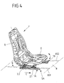
- This is part of a rail arrangement SA of a vehicle seat F Figure 4
- the adjusting device 1A exemplifies an adjusting device 1B of the rail arrangement SA which is embodied in mirror image and which corresponds to FIG Figure 4 is provided on the other (right) longitudinal side of the vehicle seat F.
- the vehicle seat F has a seat base frame G and a backrest R pivotably mounted thereon.
- the seat base frame G and thus the vehicle seat F can be displaced along a longitudinal axis L of the seat via the rail arrangement SA, and thus a longitudinal position of the vehicle seat F can be adjusted.
- the connection of the seat base frame G to the adjustment devices 1A and 1B of the rail arrangement SA takes place on bearing parts 20 (cf. Figures 1 . 2 . 3A and 3B ).
- These bearing parts 20 are each part of an adjustment unit, designed as a slide 2.1 or 2.2, of the respective (left or right) adjustment device 1A or 1B.
- the individual carriages 2.1, 2.2 of the adjustment devices 1A and 1B only protrude with the bearing part 20 from a floor B of a vehicle in which the vehicle seat F is mounted as intended.
- the remaining components of the adjustment device 1A and 1B are accommodated below the base B, so that in particular a (single) rail 3 is one Adjustment device 1A or 1B, on which the carriages 2.1 and 2.2 are slidably mounted, is fixed below the bottom B.
- the floor slots BS1 and BS2 can also extend along the floor B with a length such that the vehicle seat F can be moved between a position in the first row of seats of the vehicle and a position in the second row of seats of the vehicle.
- each rail 3 of the two adjustment devices 1A and 1B would then also have to be made correspondingly longer, in order to enable the slides 2.1 and 2.2 to be adjusted between the different positions in the first and second row of seats.
- each adjustment device 1A, 1B has a single rail 3, on which two carriages 2.1 and 2.2, each with its own electromotive drive 4.1 or 4.2, are slidably held.
- the slides 2.1 and 2.2 arranged one behind the other on the rail 3 along the longitudinal axis L can be adjusted relative to one another via the drives 4.1 and 4.2, so that a distance between the two slides 2.1 and 2.2 along the longitudinal axis L can be varied in order to, for example, incline and / or adjust the height of the seat base G.
- the drives 4.1 and 4.2 can be controlled via an electronic control unit SE for a corresponding adjustment movement relative to one another.
- a synchronous adjustment of both carriages 2.1 and 2.2 is also possible in order to move the seat base frame G completely along the rail 3.
- Both carriages 2.1 and 2.2 point for the connection of the seat base frame G to the in accordance with the intended Figure 4 assembled state of the adjustment device 1A from the bottom slot BS1 projecting bearing parts 20 each have a hinge point / screw-on point 200.
- This pivot point / screwing point 200 is provided for the connection and articulated mounting of a rocker.
- the drive 4.1 or 4.2 is also flanged to a flange section 21 of the bearing part 20, so that the respective drive 4.1 or 4.2 projects laterally on the rail 3 and its drive axis runs perpendicular to the longitudinal axis L of the seat and thus the longitudinal direction of the rail 3.
- a connection socket 40 for connecting the electronic control unit SE accessible.
- Each drive 4.1 or 4.2 also has a drive shaft for rotating a spindle nut 801. This spindle nut 801 meshes with a spindle 7, which runs parallel to the longitudinal axis L within the rail 3.
- the spindle nut 801 is in each case part of an adjusting gear 8 which interacts with the associated drive 4.1 or 4.2.
- This adjustment gear 8 each comprises a gear housing 80 in which a drive worm 800 is rotatably mounted.
- This drive worm 800 is driven via the respective drive 4.1 or 4.2 and meshes with an external toothing of the spindle nut 801.
- the spindle nut 801 meshes with the spindle 7 via an internal toothing, so that a torque applied by the respective drive 4.1 or 4.2 via the drive worm 800 in a rotary movement of the spindle nut 801 about a longitudinal axis of the spindle 7 is implemented.
- the rotation of the spindle nut 801 in turn leads to an adjustment movement of the associated slide 2.1 or 2.2 along the longitudinal axis L.
- the gear housing 80 is received on the one hand between two holding plates 81.1 and 81.2 and, for example, fixed to them, possibly by welding.
- the holding plates 81.1 and 81.2 lie opposite one another along the longitudinal axis L of the seat and have a through opening for the spindle 7 extending through the holding plates 81.1 and 81.2.
- Both carriages 2.1 and 2.2 can consequently be adjusted along a common spindle 7, namely via their mutually independent drives 4.1 and 4.2 synchronously in one and the same adjusting device and also relative to one another, in particular in different adjusting directions.
- each carriage 2.1 or 2.2 has a plurality of support elements in the form of rotatably mounted rollers 22, 23, 24 and 25. These rollers 22 to 25 are arranged in pairs on both sides of the respective adjustment gear 8.
- the adjusting mechanism 8 with the spindle nut 801 is consequently located between two pairs of two rotatable rollers 22/25 and 23/24.
- the spindle 7 extends between the two rollers 22/25 or 23/24 of a pair and is supported by rollers 22/25 and 23/24 arranged above and below the spindle 7.
- the rollers 22 to 25 of each carriage 2.1 or 2.2 thus counteract a deflection of the spindle 7, particularly in the case of a particularly long spindle 7.
- rollers 22 to 25 are supported above (in the case of the rollers 22 and 23) or below (in the case of the rollers 24 and 25) the spindle 7 on a guide profile which is firmly connected to the rail 3 or integrally formed with the rail 3 a semicircular profile 5.1 or 5.2. In this way, the rollers support 22 to 25 transverse forces from the seat base frame G and divert them into the rail 3.
- the individual rollers 22 to 25 have a convexly curved running surface LF (compare in particular Figure 3B ) on which each roller 22 to 25 can roll on the one hand on the respective semicircular profile 5.1 or 5.2 and on the other hand on the spindle 7 when the carriage 2.1 or 2.2 is adjusted along the spindle 7 and thus along the rail 3.
- LF convexly curved running surface
- rollers 22 to 25 of a carriage 2.1 or 2.2 are rotatably mounted on two bearing plates 60 and 61 which lie opposite one another transversely to the longitudinal axis L of the seat. These bearing plates 60 and 61, together with the rollers 22 to 25 mounted thereon, form a roller assembly 6 of the respective carriage 2.1 or 2.2.
- This roller assembly 6 is completely accommodated in a cavity 30 of the rail 3 and ensures the displaceability of the respective slide 2.1 or 2.2 on the rail 3.
- the adjustment gear 8 with the drive worm 800 and the spindle nut 801 is arranged between the bearing plates 60 and 61.
- the holding plates 81.1 and 81.2 connected to the gear housing 80 can be welded to the side bearing plates 60, 61.
- no separate gear housing 80 is provided for the rotatable mounting of the drive worm 800 and the accommodation of the spindle nut 801. Rather, a housing for the drive worm 800 and the spindle nut 801 is then formed by the bearing plates 60 and 61 and the holding plates 81.1 and 81.2.
- the rail 3 is designed to be open on one longitudinal side. This open long side is provided inside when the adjustment device is installed as intended, and is therefore opposite an inside of the other adjustment device 1B of the rail arrangement SA for the vehicle seat F.
- the individual carriages 2.1 and 2.2 with their bearing part 20, the drive 4.1 or 4.2 flanged onto it, the one with the Drive 4.1 or 4.2 coupled adjusting gear 8 and the roller assembly 6 are preassembled and form a preassembled assembly.
- the individual carriages 2.1 and 2.2 are then inserted from one end of the rail 3 with their roller assembly 6 into the rail 3 and are positioned as intended on the rail 3 via the spindle nut 801 meshing with the spindle 7.
- the semicircular profiles 5.1 and 5.2 located opposite one another and above and below the spindle 7 ensure on the one hand a defined guidance of the slides 2.1 and 2.2 within the rail 3 as well as a support of the transverse forces introduced by the seat base frame G.
- a support of the spindle 7 is achieved in a central region between two spindle ends via the pairs of rollers 22/25 and 23/24 spaced apart from one another along the longitudinal axis L of the seat, between which the adjusting mechanism 8 of a slide 2.1 or 2.2 is accommodated.
- a spindle holder 9 is provided at each end of the rail 3.
- the fixed spindle is held on this spindle holder 9 and fixed within the rail 3.
- the spindle holder 9 has a spindle holding part in the form of a vertigo holding plate 90.
- the spindle 7 is fixed in the rail 3 and secured against rotation about its longitudinal axis.
- the spindle holding plate 90 is detachably fixed to the rail 3 via a plurality of fastening elements in the form of screws 92 for easier assembly and disassembly.
- Two screws 92 are provided laterally on the rail 3 and screwed in on a (left) side wall 32 of the rail 3.
- Two further screws 92 are screwed in on the other (right) side of the rail 3, in each case on an upper and lower edge web 31o or 31u, which borders the open long side of the rail 3.
- the spindle holding plate 90 (with screws 92 screwed in) is fixed immovably at one end of the rail 3 inside the rail 3 via the two locking plates 91a and 91b opposite one another transversely to the longitudinal axis L of the seat.
- the spindle holding plate 90 shown is cruciform and with its sections projecting laterally and upwards and downwards in a form-fitting manner between the opposing locking plates 91a and 91b added.
- Each locking plate 91a, 91b has a corresponding recess for the positive reception of the laterally projecting sections of the spindle holding plate 90.
- One end of the rail 3 is almost completely closed in the present case via the spindle holding plate 90. This reduces the risk of dirt entering the cavity 30 of the rail 3.
- the end of the rail 3 is stiffened by the spindle holder 9 which has the spindle holding plate 90 and the locking plates 91a and 91b.
- both the spindle holding plate 90 and the lateral locking plates 91a, 91b are accommodated within the cavity 30 of the rail 3.
- the spindle holding plate 90 consequently forms, together with the locking plates 91a and 91b, a spindle holding block which is screwed onto the rail 3 and stiffens the rail profile. This can have a particularly advantageous effect on the load-bearing capacity of the (individual) rail 3.
- the adjusting device 1A shown with a single rail 3 and here independently adjustable slides 2.1 and 2.2, each provided with its own drive 4.1, 4.2, does not require a continuous upper rail on which the seat base G would be fixed on a longitudinal side of the seat. Rather, a (longitudinal seat) adjustment device 1A is provided here, which has two separately adjustable adjustment units in the form of the slides 2.1 and 2.2, each of which defines an articulation point / viewing point for the seat base frame G.
- An adjustment device 1A or 1B is thus designed without a continuous top rail, but with two short, slide-shaped top rail pieces, which are adjusted by the adjustment units 2.1 and 2.2. To be defined.
- independently controllable rocker drives for a front and a rear rocker of the seat base frame G can be provided, for example, in conjunction with a second adjusting device 1B according to the rail arrangement SA Figure 4 -
- relatively large strokes can be achieved via the carriages 2.1 and 2.2, which are adjustable relative to one another.
Landscapes
- Engineering & Computer Science (AREA)
- Aviation & Aerospace Engineering (AREA)
- Transportation (AREA)
- Mechanical Engineering (AREA)
- Seats For Vehicles (AREA)
Priority Applications (2)
| Application Number | Priority Date | Filing Date | Title |
|---|---|---|---|
| PL19155749T PL3511201T3 (pl) | 2016-12-14 | 2017-12-11 | Urządzenie regulacyjne do wzdłużnej regulacji siedzenia pojazdu |
| EP19155749.5A EP3511201B1 (de) | 2016-12-14 | 2017-12-11 | Verstelleinrichtung für die längsverstellung eines fahrzeugsitzes |
Applications Claiming Priority (2)
| Application Number | Priority Date | Filing Date | Title |
|---|---|---|---|
| DE102016225053.1A DE102016225053B4 (de) | 2016-12-14 | 2016-12-14 | Verstelleinrichtung für die Längsverstellung eines Fahrzeugsitzes |
| PCT/EP2017/082119 WO2018108762A1 (de) | 2016-12-14 | 2017-12-11 | Verstelleinrichtung für die längsverstellung eines fahrzeugsitzes |
Related Child Applications (2)
| Application Number | Title | Priority Date | Filing Date |
|---|---|---|---|
| EP19155749.5A Division EP3511201B1 (de) | 2016-12-14 | 2017-12-11 | Verstelleinrichtung für die längsverstellung eines fahrzeugsitzes |
| EP19155749.5A Division-Into EP3511201B1 (de) | 2016-12-14 | 2017-12-11 | Verstelleinrichtung für die längsverstellung eines fahrzeugsitzes |
Publications (2)
| Publication Number | Publication Date |
|---|---|
| EP3481667A1 EP3481667A1 (de) | 2019-05-15 |
| EP3481667B1 true EP3481667B1 (de) | 2020-02-12 |
Family
ID=60629711
Family Applications (2)
| Application Number | Title | Priority Date | Filing Date |
|---|---|---|---|
| EP17811585.3A Active EP3481667B1 (de) | 2016-12-14 | 2017-12-11 | Verstelleinrichtung für die längsverstellung eines fahrzeugsitzes |
| EP19155749.5A Active EP3511201B1 (de) | 2016-12-14 | 2017-12-11 | Verstelleinrichtung für die längsverstellung eines fahrzeugsitzes |
Family Applications After (1)
| Application Number | Title | Priority Date | Filing Date |
|---|---|---|---|
| EP19155749.5A Active EP3511201B1 (de) | 2016-12-14 | 2017-12-11 | Verstelleinrichtung für die längsverstellung eines fahrzeugsitzes |
Country Status (7)
| Country | Link |
|---|---|
| US (3) | US11299071B2 (pl) |
| EP (2) | EP3481667B1 (pl) |
| KR (2) | KR102270466B1 (pl) |
| CN (4) | CN110035922B (pl) |
| DE (1) | DE102016225053B4 (pl) |
| PL (1) | PL3511201T3 (pl) |
| WO (1) | WO2018108762A1 (pl) |
Families Citing this family (14)
| Publication number | Priority date | Publication date | Assignee | Title |
|---|---|---|---|---|
| DE102016225053B4 (de) * | 2016-12-14 | 2025-07-10 | Brose Fahrzeugteile SE & Co. Kommanditgesellschaft, Coburg | Verstelleinrichtung für die Längsverstellung eines Fahrzeugsitzes |
| CN113968289A (zh) * | 2018-01-10 | 2022-01-25 | 北极星工业有限公司 | 无级变速器 |
| DE102019201485B4 (de) * | 2019-02-06 | 2023-12-28 | Psa Automobiles Sa | Verstellanordnung und Verfahren zur Verstellung mindestens eines Fahrzeugsitzes eines Fahrzeugs und Fahrzeug mit der Verstellanordnung |
| ES2928913T3 (es) | 2019-06-04 | 2022-11-23 | Ims Gear Se & Co Kgaa | Accionamiento lineal, unidad de ajuste longitudinal de un asiento y automóvil |
| DE102019209171B4 (de) * | 2019-06-25 | 2023-10-26 | Brose Fahrzeugteile SE & Co. Kommanditgesellschaft, Coburg | Längsverstelleinrichtung für einen Fahrzeugsitz |
| KR102242419B1 (ko) * | 2019-11-26 | 2021-04-20 | 현대트랜시스 주식회사 | 차량용 시트 조절장치 |
| FR3110500B3 (fr) | 2020-05-25 | 2022-06-03 | Faurecia Sieges Dautomobile | Glissière pour siège de véhicule |
| EP4052959B1 (de) * | 2021-03-04 | 2024-09-25 | IMS Gear SE & Co. KGaA | Sitzlängsverstelleinheit, sitzanordnung und kraftfahrzeug |
| DE102021202962A1 (de) | 2021-03-25 | 2022-09-29 | Brose Fahrzeugteile SE & Co. Kommanditgesellschaft, Coburg | Fahrzeug mit Fahrzeugsitz |
| CN113119813B (zh) * | 2021-04-27 | 2025-09-09 | 浙江春风动力股份有限公司 | 一种滑轨结构、车辆座椅以及车辆 |
| DE102021209739A1 (de) * | 2021-09-03 | 2023-03-09 | Brose Fahrzeugteile SE & Co. Kommanditgesellschaft, Coburg | Sitzbaugruppe, Fahrzeug und Montageverfahren mit Zusatzteil für die Anbindung einer weiteren Komponente im Fahrzeuginnenraum |
| DE102022208994A1 (de) * | 2022-08-30 | 2024-02-29 | Adient Us Llc | Untergestell für einen Höheneinsteller und Höheneinsteller |
| US12391199B2 (en) | 2022-11-11 | 2025-08-19 | Polaris Industries Inc. | Utility vehicle fluid containment system |
| DE102024204692A1 (de) * | 2024-05-21 | 2025-11-27 | Brose Fahrzeugteile SE & Co. Kommanditgesellschaft, Coburg | Verstellvorrichtung für einen Fahrzeugsitz sowie Fahrzeugsitz mit einer solchen Verstellvorrichtung |
Family Cites Families (49)
| Publication number | Priority date | Publication date | Assignee | Title |
|---|---|---|---|---|
| US3405900A (en) * | 1966-02-23 | 1968-10-15 | Lear Siegler Inc | Wedge actuated seat adjuster |
| DE2846632A1 (de) * | 1978-10-26 | 1980-05-08 | Keiper Automobiltechnik Gmbh | Hoehenverstellvorrichtung fuer sitze, insbesondere kraftfahrzeugsitze |
| JP2780320B2 (ja) | 1989-03-31 | 1998-07-30 | アイシン精機株式会社 | 自動車用パワーシートスライド装置 |
| JPH0639232B2 (ja) | 1990-02-09 | 1994-05-25 | 株式会社大井製作所 | シートスライド装置 |
| US5316258A (en) | 1992-04-30 | 1994-05-31 | Itt Corporation | Power seat adjuster with drive gear force bypass |
| JPH0687361A (ja) * | 1992-09-04 | 1994-03-29 | Mitsuba Electric Mfg Co Ltd | 車両用パワーシートの駆動装置 |
| JPH08244505A (ja) * | 1995-03-13 | 1996-09-24 | Ikeda Bussan Co Ltd | 座席支持装置 |
| JPH08310285A (ja) | 1995-05-16 | 1996-11-26 | Ikuo Tanaka | 車両用追突衝撃軽減装置 |
| US5871195A (en) * | 1996-06-06 | 1999-02-16 | Lear Corporation | Vehicle power seat adjuster with one piece torsion tube bushing/spacer |
| US5711505A (en) * | 1996-09-30 | 1998-01-27 | Tachi-S Co., Ltd. | Slide rail device for jump seat |
| US5924668A (en) * | 1998-02-26 | 1999-07-20 | Meritor Automotive Canada, Inc. | Motorized vehicle seat lift mechanism |
| DE19815283C2 (de) | 1998-04-06 | 2000-07-13 | Brose Fahrzeugteile | Spindelantrieb für Verstelleinrichtungen in Kraftfahrzeugen |
| JP4079512B2 (ja) * | 1998-05-25 | 2008-04-23 | デルタ工業株式会社 | 車両用シートの減速装置 |
| SE513310C2 (sv) | 1998-12-22 | 2000-08-21 | Volvo Ab | Sätesarrangemang för ett motorfordon |
| US6217115B1 (en) * | 1999-04-20 | 2001-04-17 | Dura Global Technologies, Inc. | Simplified linkage assembly |
| FR2801543B1 (fr) | 1999-11-30 | 2004-10-15 | Aisin Seiki | Appareil vertical pour siege de vehicule |
| US20020121803A1 (en) * | 2001-03-02 | 2002-09-05 | Schooler Paul T. | Ten way power adjustable seat |
| US6517157B1 (en) | 2001-03-16 | 2003-02-11 | Johnson Controls Technology Company | Apparatus for adjusting a seat belt |
| DE10337475A1 (de) | 2003-08-08 | 2005-03-03 | Brose Fahrzeugteile Gmbh & Co. Kommanditgesellschaft, Coburg | Verstellgetriebe für ein Kraftfahrzeug |
| DE102004055643B4 (de) * | 2004-11-12 | 2014-08-07 | Sitech Sitztechnik Gmbh | Verfahren zur Sitzverstellung und Sitz |
| JP4428282B2 (ja) * | 2005-04-22 | 2010-03-10 | アイシン精機株式会社 | 車両用パワーシートスライド装置 |
| JP2007216751A (ja) | 2006-02-15 | 2007-08-30 | Mazda Motor Corp | 運転姿勢調節装置 |
| US20070252420A1 (en) * | 2006-05-01 | 2007-11-01 | Fasco Industries, Inc. | Automotive power seat motor arrangement including a monolithic frame |
| SE530679C2 (sv) | 2006-12-15 | 2008-08-12 | Scania Cv Abp | Fordonsstol med helsimultan lägesjustering |
| US7695045B2 (en) | 2007-03-30 | 2010-04-13 | Mazda Motor Corporation | Driving position adjusting device |
| CN101298077B (zh) | 2008-06-13 | 2012-07-04 | 天津绿博特环保设备制造股份公司 | 桶移位系统 |
| JP5471132B2 (ja) | 2009-08-04 | 2014-04-16 | アイシン精機株式会社 | 車両用シートスライド装置 |
| DE102009038126B4 (de) * | 2009-08-11 | 2018-12-13 | Adient Luxembourg Holding S.À R.L. | Längseinsteller für einen Fahrzeugsitz |
| EP2305512B1 (en) * | 2009-10-05 | 2014-01-01 | Delta Kogyo Co., Ltd. | Seat slide structure for vehicle |
| DE102010001847A1 (de) | 2010-02-11 | 2011-08-11 | Brose Fahrzeugteile GmbH & Co. Kommanditgesellschaft, Coburg, 96450 | Spindelgetriebe mit Verstärkung |
| DE102010029129A1 (de) | 2010-05-19 | 2011-11-24 | C. Rob. Hammerstein Gmbh & Co. Kg | Verstellvorrichtung für Kraftfahrzeugsitze, insbesondere Höhenverstellvorrichtungen |
| JP5548058B2 (ja) * | 2010-07-12 | 2014-07-16 | 本田技研工業株式会社 | 車両用シートの制御装置 |
| DE102010053892B4 (de) | 2010-12-09 | 2015-01-29 | Airbus Operations Gmbh | Sitzverstellvorrichtung sowie Luft-oder Raumfahrzeug |
| DE102011088683B4 (de) | 2010-12-21 | 2015-02-12 | Hyundai Motor Company | Stellantrieb für einen motorisch verstellbaren Kraftfahrzeugsitz mit mehreren Verstellfunktionen |
| DE102011011315A1 (de) * | 2011-02-15 | 2012-08-16 | Brose Fahrzeugteile Gmbh & Co. Kommanditgesellschaft, Coburg | Sitzschiene für Kraftfahrzeugsitze |
| EP2739503B1 (de) * | 2011-08-01 | 2018-07-18 | Adient Luxembourg Holding S.à r.l. | Schienenführung einer längsverstellung eines kraftfahrzeugsitzes |
| JP5826389B2 (ja) | 2011-08-01 | 2015-12-02 | ジョンソン コントロールズ メタルズ アンド メカニズムス ゲーエムベーハー アンド カンパニー カーゲー | 自動車シートの前後調節機構用レールガイド及びこのようなレールガイドの製造方法 |
| DE102012014379B4 (de) | 2012-04-25 | 2019-07-11 | Adient Luxembourg Holding S.À R.L. | Sitzlängsverstellung, Sitzflächenneigungsverstellung, Fahrzeugsitz |
| CN102700438A (zh) | 2012-05-03 | 2012-10-03 | 苏州忠明祥和精工有限公司 | 一种用于汽车座椅的电动滑轨 |
| EP2730456B1 (de) * | 2012-11-07 | 2017-04-26 | IMS Gear SE & Co. KGaA | Antrieb einer Sitzverstelleinrichtung für Kraftfahrzeuge |
| CN103538497B (zh) | 2013-10-29 | 2016-03-02 | 长城汽车股份有限公司 | 一种座椅调节装置及汽车座椅 |
| US9187012B2 (en) | 2013-12-12 | 2015-11-17 | Ford Global Technologies, Llc | Pivoting and reclining vehicle seating assembly |
| DE102014201582A1 (de) | 2014-01-29 | 2015-07-30 | Brose Fahrzeugteile Gmbh & Co. Kg, Coburg | Längsverstelleinrichtung zum Längsverstellen eines Fahrzeugsitzes |
| JP6456253B2 (ja) | 2014-08-11 | 2019-01-23 | 株式会社Tf−Metal | シートスライド装置 |
| DE102016224663B4 (de) | 2015-12-15 | 2019-11-21 | Lear Corporation | Schienenanordnung |
| US9855865B2 (en) | 2016-03-08 | 2018-01-02 | Honda Motor Co., Ltd. | Grip mechanism for a motor vehicle seat |
| DE102016225053B4 (de) * | 2016-12-14 | 2025-07-10 | Brose Fahrzeugteile SE & Co. Kommanditgesellschaft, Coburg | Verstelleinrichtung für die Längsverstellung eines Fahrzeugsitzes |
| US10442322B2 (en) * | 2017-11-17 | 2019-10-15 | Brose Fahrzeugteile Gmbh & Co. Kommanditgesellschaft | Easy-entry vehicle seat |
| KR102410521B1 (ko) * | 2017-12-06 | 2022-06-20 | 현대자동차주식회사 | 차량용 릴렉스 시트 |
-
2016
- 2016-12-14 DE DE102016225053.1A patent/DE102016225053B4/de active Active
-
2017
- 2017-12-11 KR KR1020197020396A patent/KR102270466B1/ko not_active Expired - Fee Related
- 2017-12-11 CN CN201780074626.9A patent/CN110035922B/zh active Active
- 2017-12-11 US US16/323,494 patent/US11299071B2/en active Active
- 2017-12-11 PL PL19155749T patent/PL3511201T3/pl unknown
- 2017-12-11 EP EP17811585.3A patent/EP3481667B1/de active Active
- 2017-12-11 CN CN202010285600.2A patent/CN111497693B/zh active Active
- 2017-12-11 CN CN201910576002.8A patent/CN110281819B/zh active Active
- 2017-12-11 KR KR1020207011216A patent/KR102368509B1/ko not_active Expired - Fee Related
- 2017-12-11 CN CN202010285599.3A patent/CN111497692B/zh active Active
- 2017-12-11 EP EP19155749.5A patent/EP3511201B1/de active Active
- 2017-12-11 WO PCT/EP2017/082119 patent/WO2018108762A1/de not_active Ceased
-
2020
- 2020-04-06 US US16/840,920 patent/US20200269730A1/en not_active Abandoned
- 2020-04-06 US US16/841,507 patent/US20200231068A1/en not_active Abandoned
Non-Patent Citations (1)
| Title |
|---|
| None * |
Also Published As
| Publication number | Publication date |
|---|---|
| DE102016225053A1 (de) | 2018-06-14 |
| KR102368509B1 (ko) | 2022-02-25 |
| PL3511201T3 (pl) | 2022-05-09 |
| US20210309129A1 (en) | 2021-10-07 |
| EP3511201B1 (de) | 2022-02-09 |
| CN111497692A (zh) | 2020-08-07 |
| US20200231068A1 (en) | 2020-07-23 |
| US11299071B2 (en) | 2022-04-12 |
| CN110035922B (zh) | 2022-01-14 |
| CN110281819A (zh) | 2019-09-27 |
| EP3481667A1 (de) | 2019-05-15 |
| US20200269730A1 (en) | 2020-08-27 |
| CN111497693A (zh) | 2020-08-07 |
| DE102016225053B4 (de) | 2025-07-10 |
| KR20190095385A (ko) | 2019-08-14 |
| KR20200043536A (ko) | 2020-04-27 |
| EP3511201A1 (de) | 2019-07-17 |
| CN111497692B (zh) | 2023-01-24 |
| CN110035922A (zh) | 2019-07-19 |
| CN111497693B (zh) | 2022-08-09 |
| WO2018108762A1 (de) | 2018-06-21 |
| KR102270466B1 (ko) | 2021-06-28 |
| CN110281819B (zh) | 2022-03-25 |
Similar Documents
| Publication | Publication Date | Title |
|---|---|---|
| EP3481667B1 (de) | Verstelleinrichtung für die längsverstellung eines fahrzeugsitzes | |
| DE102012112527B3 (de) | Nutzfahrzeugsitz mit integrierter Drehverstelleinrichtung | |
| DE102008046000B4 (de) | Sitztiefenverstellbarer Fahrzeugsitz mit einem ersten Sitzteil und einem zweiten Sitzteil | |
| EP2337704B1 (de) | Untergestell eines kraftfahrzeugsitzes mit zwei schienenpaaren, schwingen und einem sitzträger | |
| EP3374229B1 (de) | Sitzverstellmechanismus eines sitzes mit einer schwenk-schubeinheit | |
| DE112008004153B4 (de) | Einstellbarer Sitz | |
| DE102008047249A1 (de) | Rückenlehnenstruktur für einen Kraftfahrzeugsitz | |
| DE102009008500B4 (de) | Längseinstellbarer Fahrzeugsitz mit Schienen | |
| DE102015013362B4 (de) | Kopfstütze für einen Fahrzeugsitz | |
| WO2018060219A1 (de) | Verstellvorrichtung einer lordosenstütze oder eines seitenwangenverstellers mit spindelantrieb für ein sitzelement eines fahrzeugsitzes | |
| EP2739503B1 (de) | Schienenführung einer längsverstellung eines kraftfahrzeugsitzes | |
| DE102004055643B4 (de) | Verfahren zur Sitzverstellung und Sitz | |
| DE102010061788A1 (de) | Vorrichtung zur Einstellung einer Lordosenstütze | |
| DE102016219105B4 (de) | Verstellvorrichtung mit Spindelantrieb für ein Sitzelement eines Fahrzeugsitzes | |
| DE102015116480B4 (de) | Fahrzeugsitzanordnung, kraftfahrzeugsitz und befestigungsanordnung für ein fahrzeugsitzpolster | |
| WO2018077822A1 (de) | Kopfstützenanordnung mit ersten und zweiten verschwenkbaren hebelelementen für die verstellung eines kopfstützenkörpers | |
| DE19902242A1 (de) | Windstopeinrichtung | |
| DE102013001805B3 (de) | Neigungseinsteller für einen Fahrzeugsitz und Fahrzeugsitz | |
| EP1582457A1 (de) | Fahrzeugsitz, insbesondere Fluggastsitz | |
| DE102016015923B3 (de) | Fahrzeugsitz mit einer Verstelleinrichtung für die Längsverstellung | |
| DE102018100425A1 (de) | Fahrzeugsitz | |
| EP2994021B1 (de) | Lattenrost mit einem elektromotorischen möbelantrieb | |
| EP4292873A1 (de) | Kraftfahrzeugsitz | |
| DE102006028899A1 (de) | Fahrzeugsitz mit einem Sitzbereich, einer Rückenlehne und einem Untergestell | |
| DE202018102730U1 (de) | Verstelleinrichtung für die Längsverstellung eines Fahrzeugsitzes |
Legal Events
| Date | Code | Title | Description |
|---|---|---|---|
| STAA | Information on the status of an ep patent application or granted ep patent |
Free format text: STATUS: UNKNOWN |
|
| STAA | Information on the status of an ep patent application or granted ep patent |
Free format text: STATUS: THE INTERNATIONAL PUBLICATION HAS BEEN MADE |
|
| PUAI | Public reference made under article 153(3) epc to a published international application that has entered the european phase |
Free format text: ORIGINAL CODE: 0009012 |
|
| STAA | Information on the status of an ep patent application or granted ep patent |
Free format text: STATUS: REQUEST FOR EXAMINATION WAS MADE |
|
| 17P | Request for examination filed |
Effective date: 20190205 |
|
| AK | Designated contracting states |
Kind code of ref document: A1 Designated state(s): AL AT BE BG CH CY CZ DE DK EE ES FI FR GB GR HR HU IE IS IT LI LT LU LV MC MK MT NL NO PL PT RO RS SE SI SK SM TR |
|
| AX | Request for extension of the european patent |
Extension state: BA ME |
|
| REG | Reference to a national code |
Ref country code: DE Ref legal event code: R079 Ref document number: 502017003813 Country of ref document: DE Free format text: PREVIOUS MAIN CLASS: B60N0002180000 Ipc: B60N0002060000 |
|
| RIC1 | Information provided on ipc code assigned before grant |
Ipc: B60N 2/07 20060101ALI20190618BHEP Ipc: B60N 2/06 20060101AFI20190618BHEP Ipc: B60N 2/015 20060101ALI20190618BHEP |
|
| GRAP | Despatch of communication of intention to grant a patent |
Free format text: ORIGINAL CODE: EPIDOSNIGR1 |
|
| STAA | Information on the status of an ep patent application or granted ep patent |
Free format text: STATUS: GRANT OF PATENT IS INTENDED |
|
| INTG | Intention to grant announced |
Effective date: 20190911 |
|
| GRAS | Grant fee paid |
Free format text: ORIGINAL CODE: EPIDOSNIGR3 |
|
| GRAA | (expected) grant |
Free format text: ORIGINAL CODE: 0009210 |
|
| STAA | Information on the status of an ep patent application or granted ep patent |
Free format text: STATUS: THE PATENT HAS BEEN GRANTED |
|
| DAV | Request for validation of the european patent (deleted) | ||
| DAX | Request for extension of the european patent (deleted) | ||
| REG | Reference to a national code |
Ref country code: DE Ref legal event code: R081 Ref document number: 502017003813 Country of ref document: DE Owner name: BROSE FAHRZEUGTEILE SE & CO. KOMMANDITGESELLSC, DE Free format text: FORMER OWNER: BROSE FAHRZEUGTEILE GMBH & CO. KOMMANDITGESELLSCHAFT, COBURG, 96450 COBURG, DE |
|
| AK | Designated contracting states |
Kind code of ref document: B1 Designated state(s): AL AT BE BG CH CY CZ DE DK EE ES FI FR GB GR HR HU IE IS IT LI LT LU LV MC MK MT NL NO PL PT RO RS SE SI SK SM TR |
|
| REG | Reference to a national code |
Ref country code: GB Ref legal event code: FG4D Free format text: NOT ENGLISH |
|
| REG | Reference to a national code |
Ref country code: CH Ref legal event code: EP |
|
| REG | Reference to a national code |
Ref country code: AT Ref legal event code: REF Ref document number: 1231662 Country of ref document: AT Kind code of ref document: T Effective date: 20200215 |
|
| REG | Reference to a national code |
Ref country code: IE Ref legal event code: FG4D Free format text: LANGUAGE OF EP DOCUMENT: GERMAN |
|
| REG | Reference to a national code |
Ref country code: DE Ref legal event code: R096 Ref document number: 502017003813 Country of ref document: DE |
|
| RAP2 | Party data changed (patent owner data changed or rights of a patent transferred) |
Owner name: BROSE FAHRZEUGTEILE SE & CO. KOMMANDITGESELLSCHAFT, COBURG |
|
| PG25 | Lapsed in a contracting state [announced via postgrant information from national office to epo] |
Ref country code: RS Free format text: LAPSE BECAUSE OF FAILURE TO SUBMIT A TRANSLATION OF THE DESCRIPTION OR TO PAY THE FEE WITHIN THE PRESCRIBED TIME-LIMIT Effective date: 20200212 Ref country code: FI Free format text: LAPSE BECAUSE OF FAILURE TO SUBMIT A TRANSLATION OF THE DESCRIPTION OR TO PAY THE FEE WITHIN THE PRESCRIBED TIME-LIMIT Effective date: 20200212 Ref country code: NO Free format text: LAPSE BECAUSE OF FAILURE TO SUBMIT A TRANSLATION OF THE DESCRIPTION OR TO PAY THE FEE WITHIN THE PRESCRIBED TIME-LIMIT Effective date: 20200512 |
|
| REG | Reference to a national code |
Ref country code: LT Ref legal event code: MG4D |
|
| REG | Reference to a national code |
Ref country code: NL Ref legal event code: MP Effective date: 20200212 |
|
| PG25 | Lapsed in a contracting state [announced via postgrant information from national office to epo] |
Ref country code: SE Free format text: LAPSE BECAUSE OF FAILURE TO SUBMIT A TRANSLATION OF THE DESCRIPTION OR TO PAY THE FEE WITHIN THE PRESCRIBED TIME-LIMIT Effective date: 20200212 Ref country code: IS Free format text: LAPSE BECAUSE OF FAILURE TO SUBMIT A TRANSLATION OF THE DESCRIPTION OR TO PAY THE FEE WITHIN THE PRESCRIBED TIME-LIMIT Effective date: 20200612 Ref country code: LV Free format text: LAPSE BECAUSE OF FAILURE TO SUBMIT A TRANSLATION OF THE DESCRIPTION OR TO PAY THE FEE WITHIN THE PRESCRIBED TIME-LIMIT Effective date: 20200212 Ref country code: BG Free format text: LAPSE BECAUSE OF FAILURE TO SUBMIT A TRANSLATION OF THE DESCRIPTION OR TO PAY THE FEE WITHIN THE PRESCRIBED TIME-LIMIT Effective date: 20200512 Ref country code: HR Free format text: LAPSE BECAUSE OF FAILURE TO SUBMIT A TRANSLATION OF THE DESCRIPTION OR TO PAY THE FEE WITHIN THE PRESCRIBED TIME-LIMIT Effective date: 20200212 Ref country code: GR Free format text: LAPSE BECAUSE OF FAILURE TO SUBMIT A TRANSLATION OF THE DESCRIPTION OR TO PAY THE FEE WITHIN THE PRESCRIBED TIME-LIMIT Effective date: 20200513 |
|
| PG25 | Lapsed in a contracting state [announced via postgrant information from national office to epo] |
Ref country code: NL Free format text: LAPSE BECAUSE OF FAILURE TO SUBMIT A TRANSLATION OF THE DESCRIPTION OR TO PAY THE FEE WITHIN THE PRESCRIBED TIME-LIMIT Effective date: 20200212 |
|
| PG25 | Lapsed in a contracting state [announced via postgrant information from national office to epo] |
Ref country code: SM Free format text: LAPSE BECAUSE OF FAILURE TO SUBMIT A TRANSLATION OF THE DESCRIPTION OR TO PAY THE FEE WITHIN THE PRESCRIBED TIME-LIMIT Effective date: 20200212 Ref country code: DK Free format text: LAPSE BECAUSE OF FAILURE TO SUBMIT A TRANSLATION OF THE DESCRIPTION OR TO PAY THE FEE WITHIN THE PRESCRIBED TIME-LIMIT Effective date: 20200212 Ref country code: EE Free format text: LAPSE BECAUSE OF FAILURE TO SUBMIT A TRANSLATION OF THE DESCRIPTION OR TO PAY THE FEE WITHIN THE PRESCRIBED TIME-LIMIT Effective date: 20200212 Ref country code: LT Free format text: LAPSE BECAUSE OF FAILURE TO SUBMIT A TRANSLATION OF THE DESCRIPTION OR TO PAY THE FEE WITHIN THE PRESCRIBED TIME-LIMIT Effective date: 20200212 Ref country code: PT Free format text: LAPSE BECAUSE OF FAILURE TO SUBMIT A TRANSLATION OF THE DESCRIPTION OR TO PAY THE FEE WITHIN THE PRESCRIBED TIME-LIMIT Effective date: 20200705 Ref country code: ES Free format text: LAPSE BECAUSE OF FAILURE TO SUBMIT A TRANSLATION OF THE DESCRIPTION OR TO PAY THE FEE WITHIN THE PRESCRIBED TIME-LIMIT Effective date: 20200212 Ref country code: SK Free format text: LAPSE BECAUSE OF FAILURE TO SUBMIT A TRANSLATION OF THE DESCRIPTION OR TO PAY THE FEE WITHIN THE PRESCRIBED TIME-LIMIT Effective date: 20200212 Ref country code: RO Free format text: LAPSE BECAUSE OF FAILURE TO SUBMIT A TRANSLATION OF THE DESCRIPTION OR TO PAY THE FEE WITHIN THE PRESCRIBED TIME-LIMIT Effective date: 20200212 |
|
| REG | Reference to a national code |
Ref country code: DE Ref legal event code: R097 Ref document number: 502017003813 Country of ref document: DE |
|
| PLBE | No opposition filed within time limit |
Free format text: ORIGINAL CODE: 0009261 |
|
| STAA | Information on the status of an ep patent application or granted ep patent |
Free format text: STATUS: NO OPPOSITION FILED WITHIN TIME LIMIT |
|
| 26N | No opposition filed |
Effective date: 20201113 |
|
| PG25 | Lapsed in a contracting state [announced via postgrant information from national office to epo] |
Ref country code: IT Free format text: LAPSE BECAUSE OF FAILURE TO SUBMIT A TRANSLATION OF THE DESCRIPTION OR TO PAY THE FEE WITHIN THE PRESCRIBED TIME-LIMIT Effective date: 20200212 |
|
| PG25 | Lapsed in a contracting state [announced via postgrant information from national office to epo] |
Ref country code: SI Free format text: LAPSE BECAUSE OF FAILURE TO SUBMIT A TRANSLATION OF THE DESCRIPTION OR TO PAY THE FEE WITHIN THE PRESCRIBED TIME-LIMIT Effective date: 20200212 Ref country code: PL Free format text: LAPSE BECAUSE OF FAILURE TO SUBMIT A TRANSLATION OF THE DESCRIPTION OR TO PAY THE FEE WITHIN THE PRESCRIBED TIME-LIMIT Effective date: 20200212 |
|
| REG | Reference to a national code |
Ref country code: CH Ref legal event code: PL |
|
| PG25 | Lapsed in a contracting state [announced via postgrant information from national office to epo] |
Ref country code: MC Free format text: LAPSE BECAUSE OF FAILURE TO SUBMIT A TRANSLATION OF THE DESCRIPTION OR TO PAY THE FEE WITHIN THE PRESCRIBED TIME-LIMIT Effective date: 20200212 |
|
| REG | Reference to a national code |
Ref country code: BE Ref legal event code: MM Effective date: 20201231 |
|
| PG25 | Lapsed in a contracting state [announced via postgrant information from national office to epo] |
Ref country code: LU Free format text: LAPSE BECAUSE OF NON-PAYMENT OF DUE FEES Effective date: 20201211 Ref country code: IE Free format text: LAPSE BECAUSE OF NON-PAYMENT OF DUE FEES Effective date: 20201211 |
|
| PG25 | Lapsed in a contracting state [announced via postgrant information from national office to epo] |
Ref country code: LI Free format text: LAPSE BECAUSE OF NON-PAYMENT OF DUE FEES Effective date: 20201231 Ref country code: CH Free format text: LAPSE BECAUSE OF NON-PAYMENT OF DUE FEES Effective date: 20201231 |
|
| PG25 | Lapsed in a contracting state [announced via postgrant information from national office to epo] |
Ref country code: TR Free format text: LAPSE BECAUSE OF FAILURE TO SUBMIT A TRANSLATION OF THE DESCRIPTION OR TO PAY THE FEE WITHIN THE PRESCRIBED TIME-LIMIT Effective date: 20200212 Ref country code: MT Free format text: LAPSE BECAUSE OF FAILURE TO SUBMIT A TRANSLATION OF THE DESCRIPTION OR TO PAY THE FEE WITHIN THE PRESCRIBED TIME-LIMIT Effective date: 20200212 Ref country code: CY Free format text: LAPSE BECAUSE OF FAILURE TO SUBMIT A TRANSLATION OF THE DESCRIPTION OR TO PAY THE FEE WITHIN THE PRESCRIBED TIME-LIMIT Effective date: 20200212 |
|
| PG25 | Lapsed in a contracting state [announced via postgrant information from national office to epo] |
Ref country code: MK Free format text: LAPSE BECAUSE OF FAILURE TO SUBMIT A TRANSLATION OF THE DESCRIPTION OR TO PAY THE FEE WITHIN THE PRESCRIBED TIME-LIMIT Effective date: 20200212 Ref country code: AL Free format text: LAPSE BECAUSE OF FAILURE TO SUBMIT A TRANSLATION OF THE DESCRIPTION OR TO PAY THE FEE WITHIN THE PRESCRIBED TIME-LIMIT Effective date: 20200212 |
|
| PG25 | Lapsed in a contracting state [announced via postgrant information from national office to epo] |
Ref country code: BE Free format text: LAPSE BECAUSE OF NON-PAYMENT OF DUE FEES Effective date: 20201231 |
|
| GBPC | Gb: european patent ceased through non-payment of renewal fee |
Effective date: 20211211 |
|
| PG25 | Lapsed in a contracting state [announced via postgrant information from national office to epo] |
Ref country code: GB Free format text: LAPSE BECAUSE OF NON-PAYMENT OF DUE FEES Effective date: 20211211 |
|
| PGFP | Annual fee paid to national office [announced via postgrant information from national office to epo] |
Ref country code: FR Payment date: 20221110 Year of fee payment: 6 Ref country code: CZ Payment date: 20221116 Year of fee payment: 6 |
|
| REG | Reference to a national code |
Ref country code: AT Ref legal event code: MM01 Ref document number: 1231662 Country of ref document: AT Kind code of ref document: T Effective date: 20221211 |
|
| PG25 | Lapsed in a contracting state [announced via postgrant information from national office to epo] |
Ref country code: AT Free format text: LAPSE BECAUSE OF NON-PAYMENT OF DUE FEES Effective date: 20221211 |
|
| PG25 | Lapsed in a contracting state [announced via postgrant information from national office to epo] |
Ref country code: AT Free format text: LAPSE BECAUSE OF NON-PAYMENT OF DUE FEES Effective date: 20221211 |
|
| PG25 | Lapsed in a contracting state [announced via postgrant information from national office to epo] |
Ref country code: CZ Free format text: LAPSE BECAUSE OF NON-PAYMENT OF DUE FEES Effective date: 20231211 |
|
| PG25 | Lapsed in a contracting state [announced via postgrant information from national office to epo] |
Ref country code: CZ Free format text: LAPSE BECAUSE OF NON-PAYMENT OF DUE FEES Effective date: 20231211 |
|
| PG25 | Lapsed in a contracting state [announced via postgrant information from national office to epo] |
Ref country code: FR Free format text: LAPSE BECAUSE OF NON-PAYMENT OF DUE FEES Effective date: 20231231 |
|
| PG25 | Lapsed in a contracting state [announced via postgrant information from national office to epo] |
Ref country code: FR Free format text: LAPSE BECAUSE OF NON-PAYMENT OF DUE FEES Effective date: 20231231 |
|
| PGFP | Annual fee paid to national office [announced via postgrant information from national office to epo] |
Ref country code: DE Payment date: 20251231 Year of fee payment: 9 |
|
| PGFP | Annual fee paid to national office [announced via postgrant information from national office to epo] |
Ref country code: AT Payment date: 20260410 Year of fee payment: 5 |