EP3432047A1 - Runde optische kabel mit kleinem durchmesser und einer bandartigen faseroptischen struktur - Google Patents
Runde optische kabel mit kleinem durchmesser und einer bandartigen faseroptischen struktur Download PDFInfo
- Publication number
- EP3432047A1 EP3432047A1 EP18187256.5A EP18187256A EP3432047A1 EP 3432047 A1 EP3432047 A1 EP 3432047A1 EP 18187256 A EP18187256 A EP 18187256A EP 3432047 A1 EP3432047 A1 EP 3432047A1
- Authority
- EP
- European Patent Office
- Prior art keywords
- pipe
- cable
- optical
- ribbon
- optical fiber
- Prior art date
- Legal status (The legal status is an assumption and is not a legal conclusion. Google has not performed a legal analysis and makes no representation as to the accuracy of the status listed.)
- Withdrawn
Links
Images


Classifications
-
- G—PHYSICS
- G02—OPTICS
- G02B—OPTICAL ELEMENTS, SYSTEMS OR APPARATUS
- G02B6/00—Light guides; Structural details of arrangements comprising light guides and other optical elements, e.g. couplings
- G02B6/44—Mechanical structures for providing tensile strength and external protection for fibres, e.g. optical transmission cables
- G02B6/4401—Optical cables
- G02B6/4405—Optical cables with longitudinally spaced waveguide clamping
-
- G—PHYSICS
- G02—OPTICS
- G02B—OPTICAL ELEMENTS, SYSTEMS OR APPARATUS
- G02B6/00—Light guides; Structural details of arrangements comprising light guides and other optical elements, e.g. couplings
- G02B6/44—Mechanical structures for providing tensile strength and external protection for fibres, e.g. optical transmission cables
- G02B6/4401—Optical cables
- G02B6/4403—Optical cables with ribbon structure
-
- G—PHYSICS
- G02—OPTICS
- G02B—OPTICAL ELEMENTS, SYSTEMS OR APPARATUS
- G02B6/00—Light guides; Structural details of arrangements comprising light guides and other optical elements, e.g. couplings
- G02B6/44—Mechanical structures for providing tensile strength and external protection for fibres, e.g. optical transmission cables
- G02B6/4401—Optical cables
- G02B6/441—Optical cables built up from sub-bundles
Definitions
- the invention is related to an optical fiber cable that incorporates a ribbon-like structure in place of individual loose optical fibers.
- optical fiber cables Two different types are ribbon cables and cables with individual optical fibers, either loose-tube, or tightly buffered.
- advantages and disadvantages of these cables are weighed. Some of the advantages and disadvantages of these cables are listed below.
- ribbon cables include: (1) they allow for easy MPO connectorization; (2) they are relatively easy to mass splice; and (3) they provide for lower skew than cables with individual fibers. However, the design and manufacturing of ribbon cables can be more difficult.
- Fig. 2 shows an example of a conventional flat ribbon cable 4.
- This type of ribbon cable can be used by a user that requires low skew considering high speed transmission (e.g. 40 G or 100 G of parallel transmission).
- users that like the easy operation of MPO connectorization may use this type of cable.
- Two 12 fiber ribbons 5, 6 are stacked on top of each other in the cable 4.
- the cable 4 has an outer jacket 7.
- Aramid 8 is inside of the jacket and the inner shape is rectangular to keep the ribbon shape flat. This type of cable requires careful handling during the installation, because bending in incorrect directions may damage the fibers.
- FIG. 3 shows an example of a single-fiber cable 13. Twenty-four fibers can be divided into two 12 fiber bundle units 11 by the binders. An appropriate amount of aramid yarn 12 is inserted between an inner pipe (e.g., a pipe 9) and an outer pipe 10 to protect the optical fibers from tension during installation and use.
- This type of cable allows a multiple installation into limited space because of its small diameter, light weight and flexibility.
- Exemplary implementations of the present invention address at least the above problems and/or disadvantages and other disadvantages not described above. Also, the present invention is not required to overcome the disadvantages described above, and an exemplary implementation of the present invention may not overcome any of the problems listed above.
- a first embodiment of the invention is an optical fiber cable including an optical fiber ribbon in a pipe; wherein the ribbon includes at least two optical fibers arranged side by side; and wherein at least two of the optical fibers are bonded intermittently along a length of the fibers.
- the fibers being multi-mode fibers the ribbon being twisted helically, the ribbon being S-Z twisted, the ribbon being tightly buffered, the ribbon being loosely buffered with a gel is in the pipe, the ribbon being loosely buffered with an aramid yarn in the pipe, the ribbon being loosely buffered with a water blocking yarn in the pipe, the outer diameter of the jacket pipe being equal to or less than 3.0 mm and the ribbon having twelve fibers, the outer diameter of the pipe beings equal or less than 3.8 mm the cable including a second optical fiber ribbon in the pipe wherein the two optical fiber ribbons each have twelve fibers, the diameter of the pipe being equal or less than 4.8 mm and the cable including second, third and fourth optical fiber ribbons in the pipe wherein the four optical fiber ribbons each have twelve fibers, the pipe including stainless steel, the pipe including PBT, the pipe including a PBT alloy, the pipe including PE, the pipe including FRPE, and the pipe including PVC.
- a third embodiment of the invention is a cable including a strength member and an optical fiber cable including an optical fiber ribbon in a pipe, wherein the ribbon includes at least two optical fibers arranged side by side, and wherein at least two of the optical fibers are bonded intermittently along a length of said fibers.
- the optical fiber cable being surrounded by the strength member and an outer pipe and wherein the strength member comprises aramid yarn, a central member and at least two additional optical fiber cables wherein the central member is surrounded by the at least three fiber optical cables, an outer pipe, an inner pipe and an aramid yarn layer between the inner and outer pipe, an inner pipe and an armor layer between the inner pipe and the outer pipe, the strength member including wires that surround the fiber optical cables, an aramid yarn between the fiber optical cable and an outer pipe, an aluminum pipe surrounding the fiber optical cables and wire strength elements surrounding the aluminum pipe, an aluminum pipe surrounding the fiber optical cable and wire strength elements surrounding the aluminum pipe, the fiber optical cable and strength member being arranged in parallel and a pipe surrounding the fiber optical cable and strength member, the strength member including an FRP rod, the strength member including metallic wires, the strength member including a stainless steel pipe with optical fibers in the pipe.
- a fourth embodiment of the invention is a cable including an optical fiber cable including an optical fiber ribbon in a stainless steel pipe, and an outer pipe, wherein the ribbon includes at least two optical fibers arranged side by side, and wherein at least two of the optical fibers are bonded intermittently along a length of said fibers.
- Other features of the fourth embodiment may a second optical fiber ribbon in the stainless steel pipe.
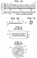
- the new concept ribbon shown in Figs. 1A-1C allows for the design of round and small cables, like single-fibers cables.
- the new cable, using the new ribbons can satisfy requirement for premise cables, such as low skew, quick connectorization and multiple installations into limited spaces.
- FIG. 1A shows the 12 fiber ribbon 1 in a Z-direction view.
- twelve fibers 1a through 11 are arranged onto X-axis.
- the fibers can have an appropriate color arrangement, but that is not required.
- a blue fiber 1a could be bonded intermittently with an orange fiber 1b which is next to blue one.
- all fibers 1a - 11, which are arranged side by side are bonded partially.
- this embodiment shows each fiber intermittently bonded to at least one other fiber, the intermittent bonding does not have to occur between each fiber. There may be some fibers that bonded to another fiber along the entire length of the fibers.
- the fibers can be bonded by any know conventional methods.
- One such known method of bonding is described in U.S. Application Publication No. 2010/0296781 , which is incorporated herein by reference.
- the bonding elements 2 are shown in Figs. 1A and IB. Note that only one bonding element 2 between fibers 1a and 1b is shown in Fig. IB. There would also be bonding elements between the other fibers. There could also be bonding elements between the fibers in Fig. 1C .
- Fig. 1A shows the bonding elements 2 arranged in a diagonal pattern across the ribbon. However, they do not have to be diagonal. Other patterns could also be used.
- the length of the bonding element can be very small relative to the length of the fibers that are not attached to the bonding element (gap 3).
- the length of the bonding element 2 could be between approximately 2 and 20 mm, with a preferable length of 10 mm.
- the gap between bonding elements could be between approximately 20 and 500 mm, with a preferable length of 50 mm.
- Preferable ratios of bonding length to gap length could be between approximately 1/5 to 1/20.
- Fig. 1B shows the y-direction view of the 12 fiber ribbon 1 that has not been inserted into a cable.
- Fig. 1C shows the y-direction view of the 12 fiber ribbon 1 that has been inserted into a cable (cable is not shown).
- mass splicing could be performed in the same way as for a conventional ribbon.
- MM fibers multi-mode fibers and single mode (SM) fibers can be used depending on the specific needs of the user.
- SM single mode
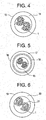
- Fig. 4 shows an example of a 24 fiber cable 15 using the new fiber ribbon.
- the structure consists of two 12 fiber ribbons 1 and a pipe 14.
- the pipe could be a single layer jacket.
- a pipe could refer to a "jacket” or a "tube.”
- the cable does not include aramid yarn inside the pipe 14.
- Each ribbon can be identified by marking on the ribbon or by using a different color of thread wound around the ribbon.
- the pipe 14 material is PVC.
- Other pipe materials such as PE, FRPE, PP, PBT or other thermoplastics could also be used.
- the cable shape is round and the cable diameter is small, like conventional single-fiber cables. This cable may also be used as a unit in a larger cable.
- the ribbon type in the cable is variable. For example, the size of the ribbons may vary, for example, from 2 fibers to 24 fibers and the total fiber counts in the cable may also vary.
- the ribbon 1 can be twisted helically, or S-Z twisted.
- the inner diameter of the pipe could be adjusted so that the cable is considered to be either “tightly buffered,” or “loosely buffered.”
- One example of a tightly buffered cable would be one in which the ratio of the cross sectional area of the inner diameter of the pipe to the cross-sectional area of the ribbon would be less than approximately 1.34. Cables that are not “tightly buffered” may be considered to be “loosely buffered.”
- Fig. 5 shows an example of a 24 fiber trunk cable 16.
- Aramid yarns 18 are embedded between the 24 fiber cable 15 shown in Fig. 4 and an outer pipe 17.
- the amount of aramid yarns 18 will depend on the tensile performance requirements (e.g. GR409 vertical or GR409 horizontal).
- outer pipe material 17 is PVC.
- Other pipe materials such as PE, FRPE, Polyurethane, Polyamide or other thermoplastics could also be used.
- the cable shape is round and the cable diameter is small as in the conventional cable shown in Fig. 3 .
- the ribbon type in the cable is variable.
- the size of the ribbons may vary, for example, from 2 fibers to 24 fibers and the total fiber counts in the cable may also vary.
- Fig. 6 shows an example of a 24 fiber cable 19 for interconnect use.
- This cable consists of two 12 fiber ribbons 1 and Aramid yarns 21 surrounded by a single layer pipe 20. An appropriate amount of yarn 21 is embedded in order to meet tensile specification (e.g. GR409 interconnect).
- the pipe 20 material could be PVC PE, FRPE, Polyurethane, Polyamide or other thermoplastics.
- the cable shape is round and one example of the cable diameter is equal or less than 3.8 mm, which is same as that of the conventional single-fibers cable. However, other diameters may be used.
- the ribbon type in the cable is variable. For example, the size of the ribbons may vary, for example, from 2 fibers to 24 fibers and the total fiber counts in the cable may also vary. For example, if one 12 fiber ribbons is in the cable the cable diameter could be equal or less than 3.0 mm. Also, if four 12 fiber ribbons are in the cable the cable diameter could be equal or less than 4.8 mm
- Fig. 7 shows an example of a 144 fiber trunk cable for vertical and horizontal use. Twelve 12 fiber cables 23 with 3.0 mm outer diameters surrounded a central strength member 24.
- the cable 23 is similar to the cable 19 in Fig. 6 , except that it has different fiber counts and outer diameter.
- An appropriate size of FRP is chosen as the central member 24 in order to meet tensile and temperature specifications (e.g. GR409 vertical or GR409 horizontal).
- the outer pipe material 25 can be PVC PE, FRPE, Polyurethane, Polyamide or other thermoplastics.
- the cable 22 shows that there are twelve 12 fiber cables 23, some of the cables 23 can be replaced with fillers which are made of PVC PE, FRPE, Polyurethane, Polyamide or other thermoplastics.
- Fig. 8 shows an example of a 288 fiber trunk cable 26 for vertical and horizontal use. Twelve 24 fiber cables 27, with 3.8 mm outer diameters surrounded a central strength member 29. The cable 27 is same as cable 19 in Fig. 6 . An appropriate size of FRP is chosen as the central member 29 in order to meet tensile specification (e.g. GR409 vertical or GR409 horizontal).
- the outer pipe material 28 can be PVC PE, FRPE, Polyurethane, Polyamide or other thermoplastics.
- the cable 26 shows that there are twelve 24 fiber cables 27, some of the cables 27 can be replaced with fillers which are made of PVC PE, FRPE, Polyurethane, Polyamide or other thermoplastics.
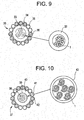
- the invention can also be used in optical ground wire (OPGW) cable. It enables mass splicing, which dramatically reduce the operation time of termination at difficult locations, such as pylons.
- Fig. 9 shows an example of a conventional Alma core type OPGW cable 30. It has three optical units 33 surrounded by an pipe 34. In this embodiment, the pipe 34 is made of aluminum. The pipe 34 is surrounded by several aluminum alloy wires 35 and several aluminum clad steel wires 36. The present invention can be incorporated into this OPGW application by replacing the optical units 33 with buffer pipes 32 containing a 12 fiber ribbon 1.
- the ribbon type is variable. For example, the size of the ribbons may vary, for example, from 2 fibers to 24 fibers.
- the buffer pipe 32 can be made of PE, PP, PBT, alloy of PBT, or other thermoplastics.
- the 12 fiber ribbon 1 can be tightly buffered by the pipe or loosely buffered by gel, silicon or air.
- Fig 10 shows an example of a conventional Centra core type OPGW cable 37.
- the cable core consists of a hermetically sealed stainless steel pipe 39 with a plurality of optical fibers 38.
- the stainless steel pipe 39 is covered by an aluminum pipe 40 and the pipe 40 is surrounded by several aluminum alloy wires 41 and several aluminum clad steel wires 42.
- the present invention can be incorporated into this OPGW application by replacing the cable core with a stainless steel tube 43 containing one or more 12 fiber ribbons 1.
- the ribbon type is variable.
- the size of the ribbons may vary, for example, from 2 fibers to 24 fibers. Gel, silicon or air can be filled into the stainless steel pipe 43.
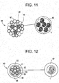
- Fig 11 shows an example of conventional Hexa core type OPGW cable 44.
- the core consists of three hermetically sealed stainless steel pipes 45, which include a plurality of fibers, and three aluminum clad steel wires 46 surrounding an aluminum clad steel wire 46.
- the core can be surrounded by an aluminum pipe (note shown) and then aluminum clad steel wires 46 and aluminum alloy wires 47.
- the present invention can be incorporated into this OPGW application by replacing the hermetically sealed stainless steel pipes 45 with a stainless steel pipe 48 containing one or more 12 fiber ribbons 1.
- the ribbon type is variable.
- the size of the ribbons may vary, for example, from 2 fibers to 24 fibers. As a result, up to 432 fibers can be in one cable.
- Loose tube cables sometimes called black jacket cables, with single fibers are often used as a feeder cable, a distribution cable and a drop cable.
- a cable with relatively higher fiber counts is used as a feeder cable.
- Ribbon splicing between a feeder cable and another cable would improve efficiency and reduce cable installation time and installation cost.
- low PMD for WDM is usually required for feeder cable.
- a feeder cable with the ribbons of this invention can satisfy both of these requirements (Ribbon splicing and low PMD).
- a distribution cable is usually laid between a feeder cable and some drop cables. It is terminated with feeder cable at one of the cable end. For the termination at this access point, ribbon splicing is efficient. Also, it is terminated with another cable (which is a feeder cable or a drop cables) at another side of cable end or at the mid pint of the cable. For the termination at this access point, single-fiber splicing can be required.
- a distribution cable that uses the ribbon of this invention can make both ribbon splicing and single-fiber splicing easier.
- Fig. 12 shows an example of a conventional loose tube cable 49.
- the cable core consists of five gel-filled buffer pipes 56.
- the buffer pipes 56 are S-Z twisted around a central strength member 53, such as FRP.
- the buffer pipes 56 are surrounded by a water blocking system 55 and a polyester tape 51.
- Above the tape is a polyethylene pipe 50.
- the pipe material can be PVC, PE, FRPE, Polyurethane, Polyamide or other thermoplastics.
- the present invention can be incorporated into this loose tube application by replacing the buffer pipes 56 with a buffer pipe 57 containing one or more 12 fiber ribbons 1.
- the ribbon type is variable.
- the size of the ribbons may vary, for example, from 2 fibers to 24 fibers.
- the buffer pipe 57 can be PE, PP, PBT, alloy of PBT and Polyether, or other thermoplastics.
- the buffer pipe can filled with gel, silicon, yarn or air.
- Fig. 13 shows an example of a conventional ADSS cable 58 for use in short spans.
- the cable core consists of four buffer pipes 64.
- the tubes are S-Z twisted around a central strength member 63, such as FRP.
- the buffer pipes 64 are surrounded by a water blocking system 65, such as water blocking yarn binder.
- a water blocking system 65 Surrounding the water blocking system is torque balance aramid yarns 61.
- the aramid yarns 61 help protect the cable from the high tension needed for aerial installation.
- a polyester tape 60 surrounds the aramid yarns 61.
- Above the tape 60 is a polyethylene outer pipe 59.
- the pipe material can be PVC, PE, FRPE, Polyurethane, Polyamide or other thermoplastics.
- the present invention can be incorporated into this ADSS application by replacing the buffer pipes 64 with a buffer pipe 66 containing one or more 12 fiber ribbons 1.
- the ribbon type is variable.
- the size of the ribbons may vary, for example, from 2 fibers to 24 fibers.
- the buffer pipe 66 can be PE, PP, PBT, alloy of PBT and Polyether, or other thermoplastics.
- the buffer pipe can filled with gel, silicon, yarn or air.
- Fig. 14 shows an example of a conventional ADSS cable 67 for use in long spans.
- the cable core consists of 24 buffer pipes 75.
- Nine of the pipes 75 are arranged over a central strength member 68, such as FRP, to form a first layer and fifteen of the pipes 75 are arranged over the first layer to form a second layer.
- a water blocking binder 76 is in between the first and second layers.
- Surrounding the second layer is a non-hygroscopic core wrap 73 and then a polyethylene inner pipe 70.
- Surrounding the inner pipe 70 is torque balance aramid yarns 72.
- the aramid yarns 72 provide supporting during the aerial installation.
- the inner and/or outer pipe material can be PVC, PE, FRPE, Polyurethane, Polyamide or other thermoplastics.
- the present invention can be incorporated into this ADSS application by replacing the buffer pipes 75 with a buffer pipe 77 containing one or more 12 fiber ribbons 1.
- the ribbon type is variable. For example, the size of the ribbons may vary, for example, from 2 fibers to 24 fibers.
- the buffer pipe 77 can be PE, PP, PBT, alloy of PBT and Polyether, or other thermoplastics.
- the buffer pipe can filled with gel, silicon, yarn or air. In addition, while this embodiment shows two pipe layers, there may only be one pipe layer.
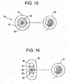
- Fig. 15 shows an example of a conventional center loose tube cable 78.
- the cable core consists of one buffer pipe 80 arranged at the center of the cable. Surrounding the core is a strength element 82, such as aramid yarn.
- a water blocking system 83 surrounds the strength member 82. Surrounding the water-blocking system 83 is a polyethylene outer pipe 79.
- the pipe material can be PVC, PE, FRPE, Polyurethane, Polyamide or other thermoplastics.
- the present invention can be incorporated into this center loose tube application by replacing the buffer pipe 80 with a buffer pipe 84 containing one or more 12 fiber ribbons 1.
- the ribbon type is variable. For example, the size of the ribbons may vary, for example, from 2 fibers to 24 fibers.
- the buffer pipe 84 can be ferrous or non-ferrous metal, PE, PP, PBT, alloy of PBT and Polyether, or other thermoplastics.
- the buffer pipe can filled with gel, silicon, yarn or air.
- Fig. 16 shows an example of another conventional center loose tube cable 85.
- Two strength members 86 are arranged on opposite sides of a buffer pipe 89 arranged at the center of the cable.
- the strength member can be any kind of ferrous or non-ferrous metal, any kind of FRP or metallic pipe with optical fibers.
- a water blocking system 87 is next to the strength members 86 and buffer pipe 89.
- An outer pipe 88 surrounds the interior elements.
- the pipe material can be PVC, PE, FRPE, Polyurethane, Polyamide or other thermoplastics.
- the present invention can be incorporated into this center loose tube application by replacing the buffer pipe 89 with a buffer pipe 91 containing one or more 12 fiber ribbons 1.
- the ribbon type is variable.
- the size of the ribbons may vary, for example, from 2 fibers to 24 fibers.
- the buffer pipe 91 can be ferrous or non-ferrous metal, PE, PP, PBT, alloy of PBT and Polyether, or other thermoplastics.
- the buffer pipe can filled with gel, silicon, yarn or air.
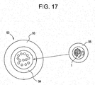
- Fig. 17 shows an example of a conventional logging cable 92.
- the cable core consists of one stainless steel pipe 94 arranged at the center of the cable. Surrounding the stainless steel pipe 94 is a polyethylene outer pipe 93.
- the pipe material can be PVC, PE, FRPE, Polyurethane, Polyamide or other thermoplastics.
- the present invention can be incorporated into this center loose tube application by replacing the stainless steel pipe 94 with a buffer pipe 95 containing one or more 12 fiber ribbons 1.
- the ribbon type is variable. For example, the size of the ribbons may vary, for example, from 2 fibers to 24 fibers.
- the buffer pipe 95 can be ferrous or non-ferrous metal, PE, PP, PBT, alloy of PBT and Polyether, or other thermoplastics.
- the buffer pipe can filled with gel, silicon, yarn or air.
Landscapes
- Physics & Mathematics (AREA)
- General Physics & Mathematics (AREA)
- Optics & Photonics (AREA)
- Light Guides In General And Applications Therefor (AREA)
- Insulated Conductors (AREA)
- Ropes Or Cables (AREA)
- Laying Of Electric Cables Or Lines Outside (AREA)
Priority Applications (1)
| Application Number | Priority Date | Filing Date | Title |
|---|---|---|---|
| EP18187256.5A EP3432047A1 (de) | 2012-05-02 | 2012-05-02 | Runde optische kabel mit kleinem durchmesser und einer bandartigen faseroptischen struktur |
Applications Claiming Priority (3)
| Application Number | Priority Date | Filing Date | Title |
|---|---|---|---|
| EP12875982.6A EP2845043A4 (de) | 2012-05-02 | 2012-05-02 | Runde optische kabel mit kleinem durchmesser und einer bandartigen faseroptischen struktur |
| EP18187256.5A EP3432047A1 (de) | 2012-05-02 | 2012-05-02 | Runde optische kabel mit kleinem durchmesser und einer bandartigen faseroptischen struktur |
| PCT/US2012/036076 WO2013165407A1 (en) | 2012-05-02 | 2012-05-02 | Round and small diameter optical cables with a ribbon-like optical fiber structure |
Related Parent Applications (1)
| Application Number | Title | Priority Date | Filing Date |
|---|---|---|---|
| EP12875982.6A Division EP2845043A4 (de) | 2012-05-02 | 2012-05-02 | Runde optische kabel mit kleinem durchmesser und einer bandartigen faseroptischen struktur |
Publications (1)
| Publication Number | Publication Date |
|---|---|
| EP3432047A1 true EP3432047A1 (de) | 2019-01-23 |
Family
ID=49514668
Family Applications (2)
| Application Number | Title | Priority Date | Filing Date |
|---|---|---|---|
| EP18187256.5A Withdrawn EP3432047A1 (de) | 2012-05-02 | 2012-05-02 | Runde optische kabel mit kleinem durchmesser und einer bandartigen faseroptischen struktur |
| EP12875982.6A Withdrawn EP2845043A4 (de) | 2012-05-02 | 2012-05-02 | Runde optische kabel mit kleinem durchmesser und einer bandartigen faseroptischen struktur |
Family Applications After (1)
| Application Number | Title | Priority Date | Filing Date |
|---|---|---|---|
| EP12875982.6A Withdrawn EP2845043A4 (de) | 2012-05-02 | 2012-05-02 | Runde optische kabel mit kleinem durchmesser und einer bandartigen faseroptischen struktur |
Country Status (6)
| Country | Link |
|---|---|
| US (10) | US20150234139A1 (de) |
| EP (2) | EP3432047A1 (de) |
| JP (1) | JP2015517679A (de) |
| AU (7) | AU2012379018B2 (de) |
| CA (3) | CA2871108C (de) |
| WO (1) | WO2013165407A1 (de) |
Families Citing this family (41)
| Publication number | Priority date | Publication date | Assignee | Title |
|---|---|---|---|---|
| JP6639773B2 (ja) * | 2014-09-17 | 2020-02-05 | 古河電気工業株式会社 | ルースチューブ型光ファイバユニット |
| US9746630B2 (en) * | 2015-01-15 | 2017-08-29 | Corning Optical Communications LLC | Hybrid optical fiber ribbon and power cable |
| JP6592909B2 (ja) * | 2015-02-03 | 2019-10-23 | 住友電気工業株式会社 | 光ケーブル及びその製造方法 |
| WO2016163190A1 (ja) * | 2015-04-07 | 2016-10-13 | 株式会社フジクラ | ルースチューブ、ルースチューブ型光ファイバケーブル、ルースチューブの光ファイバテープの単心分離方法、ルースチューブの製造方法、及び、複数の光ファイバの集線方法 |
| JP6641480B2 (ja) | 2015-07-31 | 2020-02-05 | コーニング オプティカル コミュニケイションズ リミテッド ライアビリティ カンパニー | ロール可能な光ファイバリボン |
| US9869838B2 (en) * | 2015-11-25 | 2018-01-16 | Fujikura Ltd. | Optical fiber cable and method of manufacturing same |
| JP6657976B2 (ja) * | 2016-01-13 | 2020-03-04 | 住友電気工業株式会社 | 間欠連結型光ファイバテープ心線および光ケーブル |
| US10585255B2 (en) * | 2016-01-13 | 2020-03-10 | Sumitomo Electric Industries, Ltd. | Intermittent-connection-type optical fiber ribbon with thick and thin vertical lines and method for manufacturing |
| JP2017134267A (ja) | 2016-01-28 | 2017-08-03 | 住友電気工業株式会社 | 光ファイバケーブル |
| JP6958361B2 (ja) * | 2016-01-28 | 2021-11-02 | 住友電気工業株式会社 | 光ファイバケーブル |
| US9880368B2 (en) * | 2016-02-02 | 2018-01-30 | Ofs Fitel, Llc | Method for high speed processing of partially bonded ribbon structures |
| JP6711119B2 (ja) * | 2016-05-10 | 2020-06-17 | 住友電気工業株式会社 | 光ファイバテープ心線、光ファイバケーブル |
| CN110268296A (zh) | 2017-01-25 | 2019-09-20 | Afl电信有限责任公司 | 减小直径的加固光纤配电线缆 |
| US11029477B2 (en) | 2017-03-21 | 2021-06-08 | Sumitomo Electric Industries, Ltd. | Optical fiber cable |
| US9977211B1 (en) * | 2017-04-21 | 2018-05-22 | Afl Telecommunications Llc | Optical connection terminals for fiber optic communications networks |
| WO2019032332A1 (en) * | 2017-08-08 | 2019-02-14 | Corning Research & Development Corporation | RIBBON FIBER RIBBON WITH LOW MITIGATION, OPTICAL FIBER WITH LARGE DIAMETER OF FASHION FIELD AND CABLE |
| US11131823B2 (en) * | 2017-11-14 | 2021-09-28 | Incab, LLC | Ground wire with optical fibers |
| US10914906B2 (en) | 2018-01-18 | 2021-02-09 | Sumitomo Electric Industries, Ltd. | Optical fiber cable |
| US20210055491A1 (en) * | 2018-03-29 | 2021-02-25 | Sterlite Technologies Limited | Micro sheath buffer tube with rollable ribbons |
| US11262516B2 (en) * | 2018-07-05 | 2022-03-01 | Prysmian S.P.A. | High density optical cables |
| US11378766B2 (en) | 2018-11-06 | 2022-07-05 | Sumitomo Electric Industries, Ltd. | Optical fiber cable |
| US11125959B2 (en) * | 2018-12-06 | 2021-09-21 | Sterlite Technologies Limited | Flat drop optical fiber cable |
| CA3132027A1 (en) | 2019-03-29 | 2020-10-08 | Bradley Jerome Blazer | Optical fiber cable with parallel ribbon subunits |
| US11131817B2 (en) | 2019-05-09 | 2021-09-28 | Go!Foton Holdings, Inc. | Multi-fiber cable |
| EP3988977B1 (de) | 2019-06-19 | 2024-07-24 | Sumitomo Electric Industries, Ltd. | Glasfaserkabel |
| US11960137B2 (en) * | 2019-07-16 | 2024-04-16 | Sterlite Technologies Limited | Intermittently bonded optical fibre ribbon |
| US11579387B2 (en) * | 2019-08-14 | 2023-02-14 | Sterlite Technologies Limited | Arrangement of optical fibre ribbon stack and an optical fibre ribbon thereof |
| US11693201B2 (en) * | 2020-02-27 | 2023-07-04 | Sterlite Technologies Limited | Intermittently bonded optical fibre ribbon with unequal bond and gap lengths |
| JPWO2022004666A1 (de) | 2020-06-29 | 2022-01-06 | ||
| AU2021335225B2 (en) | 2020-08-31 | 2024-09-12 | Corning Research & Development Corporation | Intermittently bonded ribbon with intermittent bonds created with a wet-on-wet process |
| WO2022086700A1 (en) * | 2020-10-19 | 2022-04-28 | Corning Research & Development Corporation | Ribbon with non-overlapping intermittent bonds between optical fiber subunits |
| EP4241123A4 (de) * | 2020-11-05 | 2024-07-31 | Weinert Industries AG | Faserisolator mit faseroptischem kabel |
| WO2022108796A1 (en) | 2020-11-19 | 2022-05-27 | Corning Research & Development Corporation | High density,low diameter cable with rollable fiber optic ribbon |
| WO2022153970A1 (ja) | 2021-01-12 | 2022-07-21 | 住友電気工業株式会社 | 光ファイバケーブル及びコネクタ付きケーブル |
| EP4323819A4 (de) * | 2021-04-13 | 2025-02-12 | Ofs Fitel Llc | Aufrollbares glasfaserband mit bindematrixmaterial mit niedrigem jungmodul |
| WO2023003056A1 (ko) * | 2021-07-21 | 2023-01-26 | 엘에스전선 주식회사 | 광섬유 리본 |
| WO2023039099A1 (en) * | 2021-09-10 | 2023-03-16 | Commscope Technologies Llc | Method of separating a ribbon of optical fibers |
| CA3213139A1 (en) | 2021-10-28 | 2023-05-04 | Ls Cable & System Ltd. | Optical cable |
| WO2023175961A1 (ja) | 2022-03-18 | 2023-09-21 | 住友電気工業株式会社 | 光ファイバケーブル |
| JP7743809B2 (ja) | 2022-04-11 | 2025-09-25 | 住友電気工業株式会社 | 光ファイバケーブルの敷設方法 |
| US12455424B2 (en) * | 2022-06-29 | 2025-10-28 | Corning Research & Development Corporation | Fiber optic cable assembly with high packing density and method of making same |
Citations (3)
| Publication number | Priority date | Publication date | Assignee | Title |
|---|---|---|---|---|
| JPH0922619A (ja) * | 1995-07-04 | 1997-01-21 | Hitachi Cable Ltd | 光ファイバ複合架空地線 |
| JP2007279226A (ja) * | 2006-04-04 | 2007-10-25 | Fujikura Ltd | 光ファイバテープ心線及び前記光ファイバテープ心線を収納した光ファイバケーブル |
| US20100296781A1 (en) | 2008-01-08 | 2010-11-25 | Fujikura Ltd. | Optical fiber ribbon capable of branching and method for making fiber ribbon branch |
Family Cites Families (86)
| Publication number | Priority date | Publication date | Assignee | Title |
|---|---|---|---|---|
| US7078A (en) * | 1850-02-12 | Machine for cutting cotton-stalks in the field | ||
| NL8403629A (nl) | 1984-05-23 | 1985-12-16 | Philips Nv | Optische bandkabel, methode voor de vervaardiging ervan en een uit verscheidene bandkabels samengestelde optische kabel. |
| JPH0631293B2 (ja) | 1987-12-11 | 1994-04-27 | 東洋紡績株式会社 | マルトオリゴ糖誘導体およびアミラーゼ活性測定用試薬 |
| JPH01157006A (ja) * | 1988-10-28 | 1989-06-20 | Fujikura Ltd | 光ケーブル入り金属撚線 |
| US5268971A (en) | 1991-11-07 | 1993-12-07 | Alcatel Na Cable Systems, Inc. | Optical fiber/metallic conductor composite cable |
| NO914353L (no) * | 1991-11-07 | 1993-05-10 | Alcatel Stk As | Fiberoptisk kabel |
| GB9126232D0 (en) | 1991-12-11 | 1992-02-12 | Bicc Plc | An improved composite overhead electric and optical conductor |
| US5495546A (en) * | 1994-04-13 | 1996-02-27 | Bottoms, Jr.; Jack | Fiber optic groundwire with coated fiber enclosures |
| US5542020A (en) | 1994-06-10 | 1996-07-30 | Commscope, Inc. | Fiber optic cable having extended contraction window and associated method and apparatus for fabricating the cable |
| JP3685520B2 (ja) | 1995-06-01 | 2005-08-17 | 昭和電線電纜株式会社 | 光ファイバ心線 |
| JP3773584B2 (ja) | 1996-03-04 | 2006-05-10 | トヨクニ電線株式会社 | 光ファイバーテープケーブル |
| US6229944B1 (en) * | 1997-02-04 | 2001-05-08 | Sumitomo Electric Industries, Ltd. | Optical fiber cable |
| US5857051A (en) | 1997-04-21 | 1999-01-05 | Lucent Technologies Inc. | High density riser and plenum breakout cables for indoor and outdoor cable applications |
| US5966489A (en) | 1997-06-30 | 1999-10-12 | Siecor Corporation | Fiber optic ribbon interconnect cable |
| US6088499A (en) * | 1997-09-30 | 2000-07-11 | Siecor Corporation | Fiber optic cable with ripcord |
| JPH11160593A (ja) | 1997-11-28 | 1999-06-18 | Ocean Cable Co Ltd | 海底光ケーブル |
| JPH11165593A (ja) | 1997-12-07 | 1999-06-22 | Toyoda Gosei Co Ltd | アンテナ組込みカウルルーバ |
| US6259844B1 (en) | 1997-12-15 | 2001-07-10 | Siecor Operations, Llc | Strengthened fiber optic cable |
| US6574400B1 (en) * | 1998-03-26 | 2003-06-03 | Corning Cable Systems Llc | Fiber optic cable with water blocking features |
| KR100322123B1 (ko) | 1998-11-18 | 2002-03-08 | 윤종용 | 스틸튜브를이용한광섬유복합가공지선 |
| KR20000033196A (ko) | 1998-11-20 | 2000-06-15 | 윤종용 | 스틸튜브를 이용한 광섬유 복합가공지선 |
| US6215931B1 (en) * | 1999-01-26 | 2001-04-10 | Alcatel | Flexible thermoplastic polyolefin elastomers for buffering transmission elements in a telecommunications cable |
| JP3844418B2 (ja) | 1999-02-12 | 2006-11-15 | 株式会社荏原製作所 | 容積式送液装置 |
| US7006740B1 (en) * | 1999-05-28 | 2006-02-28 | Corning Cable Systems, Llc | Communication cable having a soft housing |
| JP3728988B2 (ja) | 1999-08-11 | 2005-12-21 | 凸版印刷株式会社 | 液体用包装容器 |
| CA2324089C (en) * | 1999-10-22 | 2008-10-14 | Richard Chamberlain | High fiber count, compact, loose tube optical fiber cable employing ribbon units and flexible buffer tubes |
| US6185352B1 (en) * | 2000-02-24 | 2001-02-06 | Siecor Operations, Llc | Optical fiber ribbon fan-out cables |
| US6459837B1 (en) | 2000-07-20 | 2002-10-01 | Pirelli Cables And Systems Llc | Optical fiber cable with single strength member unit in cable outer jacket |
| US6584257B1 (en) | 2000-12-27 | 2003-06-24 | Corning Cable Systems, Llc | Fiber optic assembly and method of making same |
| US6690867B2 (en) | 2001-08-31 | 2004-02-10 | Corning Cable Systems Llc | Optical interconnect assemblies and methods therefor |
| US6631229B1 (en) | 2001-09-06 | 2003-10-07 | Fitel Usa Corp | Water blocking optical fiber cable |
| US6895156B2 (en) * | 2001-10-09 | 2005-05-17 | 3M Innovative Properties Company | Small diameter, high strength optical fiber |
| US6749446B2 (en) | 2001-10-10 | 2004-06-15 | Alcatel | Optical fiber cable with cushion members protecting optical fiber ribbon stack |
| US6654525B2 (en) | 2001-10-10 | 2003-11-25 | Alcatel | Central strength member with reduced radial stiffness |
| US6775445B2 (en) * | 2002-01-11 | 2004-08-10 | Fujikura Ltd. | Optical fiber drop cable |
| JP2003215412A (ja) | 2002-01-22 | 2003-07-30 | Occ Corp | 金属管被覆光ファイバケーブルおよびその製造方法、ならびにそれを用いた架空地線 |
| KR100442687B1 (ko) * | 2002-04-30 | 2004-08-02 | 삼성전자주식회사 | 루즈튜브 리본 광케이블 |
| US6681071B2 (en) * | 2002-05-15 | 2004-01-20 | Fitel Usa Corp. | Dry core indoor/outdoor fiber optic cable |
| JP4217908B2 (ja) | 2002-05-17 | 2009-02-04 | 住友電気工業株式会社 | テープ状光ファイバ心線、その製造方法、テープ心線付きコネクタ、テープ心線付き光ファイバアレイ、および光配線システム |
| US7116872B2 (en) | 2002-05-28 | 2006-10-03 | Sumitomo Electric Industries, Ltd. | Optical fiber tape core |
| US7471862B2 (en) | 2002-12-19 | 2008-12-30 | Corning Cable Systems, Llc | Dry fiber optic cables and assemblies |
| US7231119B2 (en) | 2002-12-19 | 2007-06-12 | Corning Cable Systems, Llc. | Dry fiber optic assemblies and cables |
| US6922511B2 (en) | 2003-03-31 | 2005-07-26 | Corning Cable Systems Llc | Fiber optic assemblies and cables having subunits with a security feature |
| JP2005070770A (ja) | 2003-08-04 | 2005-03-17 | Sumitomo Electric Ind Ltd | 光ファイバケーブル |
| JP4055000B2 (ja) | 2003-08-11 | 2008-03-05 | 住友電気工業株式会社 | 光ファイバケーブル、光ファイバケーブルの製造方法及び光ファイバケーブルの製造装置 |
| US6876798B2 (en) * | 2003-08-29 | 2005-04-05 | Corning Cable Systems Llc | Fiber optic cable having a ripcord |
| KR100506860B1 (ko) * | 2003-12-03 | 2005-08-08 | 엘에스전선 주식회사 | 광섬유 복합 전력 케이블 |
| JP2005300698A (ja) | 2004-04-08 | 2005-10-27 | Yazaki Corp | スロット型光ケーブル及び光ケーブル。 |
| CN1942798A (zh) * | 2004-04-14 | 2007-04-04 | 日立电线株式会社 | 光纤带单元以及光缆 |
| US7206481B2 (en) * | 2004-12-21 | 2007-04-17 | Corning Cable Systems, Llc. | Fiber optic cables manufactured as an assembly and method for manufacturing the same |
| DE102005001670B3 (de) | 2005-01-13 | 2006-08-24 | CCS Technology, Inc., Wilmington | Kabel mit Brandschutzeigenschaften und Verfahren zur Herstellung eines solchen Kabels |
| US7006741B1 (en) | 2005-03-22 | 2006-02-28 | Bi Yu | Contact-field optical microscope |
| US7509009B2 (en) * | 2005-03-23 | 2009-03-24 | Tomoegawa Paper Co., Ltd | Optical fiber structure and method of manufacturing same |
| US7742667B2 (en) | 2005-06-08 | 2010-06-22 | Commscope, Inc. Of North Carolina | Fiber optic cables and methods for forming the same |
| JP2007108424A (ja) | 2005-10-13 | 2007-04-26 | Sumitomo Electric Ind Ltd | 光ケーブル |
| DE102006004011A1 (de) | 2006-01-27 | 2007-08-09 | CCS Technology, Inc., Wilmington | Optisches Kabel und Verfahren zur Herstellung eines optischen Kabels |
| US20080285924A1 (en) | 2007-05-15 | 2008-11-20 | Graveston Mark G | Optical fiber cables |
| US7639915B2 (en) | 2007-06-28 | 2009-12-29 | Draka Comteq B.V. | Optical fiber cable having a deformable coupling element |
| US8041167B2 (en) * | 2007-11-09 | 2011-10-18 | Draka Comteq, B.V. | Optical-fiber loose tube cables |
| EP2206001B1 (de) | 2007-11-09 | 2014-04-16 | Draka Comteq B.V. | Auf mikroebene biegesteife glasfaser |
| EP4071532A1 (de) * | 2008-05-28 | 2022-10-12 | Commscope Technologies LLC | Glasfaserkabel |
| KR20100000036A (ko) | 2008-06-24 | 2010-01-06 | 엘에스전선 주식회사 | 광섬유 케이블 |
| JP4619424B2 (ja) * | 2008-06-30 | 2011-01-26 | 日本電信電話株式会社 | 光ファイバケーブル |
| CN102681119B (zh) * | 2008-06-30 | 2015-01-28 | 日本电信电话株式会社 | 光纤缆线以及光纤带 |
| EP2163927B1 (de) | 2008-09-12 | 2013-04-24 | CCS Technology Inc. | Glasfaserkabel mit strangförmigen Mikromodulen und Vorrichtung zur Herstellung des Glasfaserkabels |
| FR2957153B1 (fr) * | 2010-03-02 | 2012-08-10 | Draka Comteq France | Fibre optique multimode a large bande passante et a faibles pertes par courbure |
| JP2011100115A (ja) * | 2009-10-06 | 2011-05-19 | Fujikura Ltd | 光ファイバケーブル |
| AU2010321863B2 (en) * | 2009-11-20 | 2014-09-25 | Adc Telecommunications, Inc. | Fiber optic cable |
| US20110194825A1 (en) * | 2010-02-10 | 2011-08-11 | Donald Ray Parris | Method of forming an optical fiber buffer tube |
| JP5227996B2 (ja) | 2010-04-05 | 2013-07-03 | 株式会社フジクラ | 光ファイバテープ心線、光ファイバケーブル及び配線形態 |
| JP5411784B2 (ja) * | 2010-04-07 | 2014-02-12 | 住友電気工業株式会社 | 光ファイバテープ心線の製造方法 |
| JP6017415B2 (ja) * | 2010-04-30 | 2016-11-02 | コーニング オプティカル コミュニケイションズ リミテッド ライアビリティ カンパニー | 接近特徴部付き光ファイバケーブル及びその製造方法 |
| JP5309098B2 (ja) | 2010-08-19 | 2013-10-09 | 株式会社フジクラ | 光ファイバテープの製造方法及びこの製造方法を実行する光ファイバテープの製造装置並びにこの製造方法により製造された光ファイバテープ |
| KR101261320B1 (ko) | 2011-05-03 | 2013-05-07 | 에쓰이에이치에프코리아 (주) | 광전 복합 케이블 |
| JP5309189B2 (ja) | 2011-06-03 | 2013-10-09 | 株式会社フジクラ | 光ファイバテープ心線の製造方法及びその製造方法で製造した光ファイバテープ心線 |
| US8463096B2 (en) * | 2011-09-26 | 2013-06-11 | Ofs Fitel, Llc | Double jacket optical fiber cables |
| US8682124B2 (en) * | 2011-10-13 | 2014-03-25 | Corning Cable Systems Llc | Access features of armored flat fiber optic cable |
| TW201326932A (zh) * | 2011-11-17 | 2013-07-01 | Sumitomo Electric Industries | 光纜 |
| US9256043B2 (en) * | 2012-02-03 | 2016-02-09 | Corning Cable Systems Llc | Strength member system for fiber optic cable |
| US8909014B2 (en) * | 2012-04-27 | 2014-12-09 | Corning Cable Systems Llc | Fiber optic cable with access features and jacket-to-core coupling, and methods of making the same |
| US9031371B2 (en) * | 2012-05-08 | 2015-05-12 | Sumitomo Electric Industries, Ltd. | Multi-mode optical fiber |
| JP2014211512A (ja) * | 2013-04-18 | 2014-11-13 | 住友電気工業株式会社 | 光ファイバコード |
| JP5719003B2 (ja) | 2013-10-02 | 2015-05-13 | 株式会社フジクラ | テープ供給方法及びテープ供給装置 |
| US9594226B2 (en) | 2013-10-18 | 2017-03-14 | Corning Optical Communications LLC | Optical fiber cable with reinforcement |
| JP5719052B1 (ja) | 2014-03-06 | 2015-05-13 | 株式会社フジクラ | 光ケーブル |
| JP6569429B2 (ja) * | 2015-09-25 | 2019-09-04 | 住友電気工業株式会社 | 光ファイバテープ心線 |
-
2012
- 2012-05-02 EP EP18187256.5A patent/EP3432047A1/de not_active Withdrawn
- 2012-05-02 JP JP2015510236A patent/JP2015517679A/ja active Pending
- 2012-05-02 EP EP12875982.6A patent/EP2845043A4/de not_active Withdrawn
- 2012-05-02 WO PCT/US2012/036076 patent/WO2013165407A1/en not_active Ceased
- 2012-05-02 CA CA2871108A patent/CA2871108C/en active Active
- 2012-05-02 CA CA3178019A patent/CA3178019A1/en active Pending
- 2012-05-02 US US13/994,245 patent/US20150234139A1/en not_active Abandoned
- 2012-05-02 AU AU2012379018A patent/AU2012379018B2/en active Active
- 2012-05-02 CA CA3048873A patent/CA3048873C/en active Active
-
2016
- 2016-11-11 US US15/349,399 patent/US9958627B2/en active Active
-
2017
- 2017-05-02 AU AU2017202907A patent/AU2017202907B2/en active Active
-
2018
- 2018-02-07 US US15/890,845 patent/US10520691B2/en active Active
- 2018-07-11 US US16/032,791 patent/US10527807B2/en active Active
- 2018-07-12 AU AU2018205136A patent/AU2018205136B2/en active Active
-
2019
- 2019-11-18 US US16/687,016 patent/US10955630B2/en active Active
- 2019-11-19 US US16/688,387 patent/US11231556B2/en active Active
-
2020
- 2020-05-28 AU AU2020203524A patent/AU2020203524B2/en active Active
-
2021
- 2021-04-16 US US17/232,843 patent/US11592632B2/en active Active
-
2022
- 2022-02-04 AU AU2022200762A patent/AU2022200762B2/en active Active
- 2022-07-22 US US17/871,013 patent/US12164165B2/en active Active
-
2023
- 2023-08-24 AU AU2023219941A patent/AU2023219941B2/en active Active
-
2024
- 2024-10-31 US US18/932,811 patent/US20250052967A1/en active Pending
- 2024-12-13 AU AU2024278421A patent/AU2024278421A1/en active Pending
-
2025
- 2025-07-03 US US19/259,695 patent/US20250334763A1/en active Pending
Patent Citations (3)
| Publication number | Priority date | Publication date | Assignee | Title |
|---|---|---|---|---|
| JPH0922619A (ja) * | 1995-07-04 | 1997-01-21 | Hitachi Cable Ltd | 光ファイバ複合架空地線 |
| JP2007279226A (ja) * | 2006-04-04 | 2007-10-25 | Fujikura Ltd | 光ファイバテープ心線及び前記光ファイバテープ心線を収納した光ファイバケーブル |
| US20100296781A1 (en) | 2008-01-08 | 2010-11-25 | Fujikura Ltd. | Optical fiber ribbon capable of branching and method for making fiber ribbon branch |
Also Published As
Similar Documents
| Publication | Publication Date | Title |
|---|---|---|
| AU2023219941B2 (en) | Round and small diameter optical cables with a ribbon-like optical fiber structure | |
| US7742667B2 (en) | Fiber optic cables and methods for forming the same | |
| US9651753B2 (en) | Fiber optic ribbon cable | |
| JP2018173649A (ja) | リボン型光ファイバー構造体を有する円形で小径の光ケーブル | |
| JP2017004977A (ja) | リボン型光ファイバー構造体を有する円形で小径の光ケーブル |
Legal Events
| Date | Code | Title | Description |
|---|---|---|---|
| PUAI | Public reference made under article 153(3) epc to a published international application that has entered the european phase |
Free format text: ORIGINAL CODE: 0009012 |
|
| STAA | Information on the status of an ep patent application or granted ep patent |
Free format text: STATUS: THE APPLICATION HAS BEEN PUBLISHED |
|
| AC | Divisional application: reference to earlier application |
Ref document number: 2845043 Country of ref document: EP Kind code of ref document: P |
|
| AK | Designated contracting states |
Kind code of ref document: A1 Designated state(s): AL AT BE BG CH CY CZ DE DK EE ES FI FR GB GR HR HU IE IS IT LI LT LU LV MC MK MT NL NO PL PT RO RS SE SI SK SM TR |
|
| RIN1 | Information on inventor provided before grant (corrected) |
Inventor name: HASHIMOTO,, YOSHIO Inventor name: BAKER,, DOUG Inventor name: OSATO,, KEN Inventor name: CIGNARALE,, JOSEPH |
|
| STAA | Information on the status of an ep patent application or granted ep patent |
Free format text: STATUS: REQUEST FOR EXAMINATION WAS MADE |
|
| 17P | Request for examination filed |
Effective date: 20190717 |
|
| RBV | Designated contracting states (corrected) |
Designated state(s): AL AT BE BG CH CY CZ DE DK EE ES FI FR GB GR HR HU IE IS IT LI LT LU LV MC MK MT NL NO PL PT RO RS SE SI SK SM TR |
|
| STAA | Information on the status of an ep patent application or granted ep patent |
Free format text: STATUS: EXAMINATION IS IN PROGRESS |
|
| 17Q | First examination report despatched |
Effective date: 20200403 |
|
| STAA | Information on the status of an ep patent application or granted ep patent |
Free format text: STATUS: THE APPLICATION HAS BEEN WITHDRAWN |
|
| 18W | Application withdrawn |
Effective date: 20200527 |