EP3388720B1 - Struktur zur vermeidung von schmiermittelundichtigkeiten in einem untersetzungsgetriebe - Google Patents
Struktur zur vermeidung von schmiermittelundichtigkeiten in einem untersetzungsgetriebe Download PDFInfo
- Publication number
- EP3388720B1 EP3388720B1 EP18174191.9A EP18174191A EP3388720B1 EP 3388720 B1 EP3388720 B1 EP 3388720B1 EP 18174191 A EP18174191 A EP 18174191A EP 3388720 B1 EP3388720 B1 EP 3388720B1
- Authority
- EP
- European Patent Office
- Prior art keywords
- grease
- electric motor
- output shaft
- gear
- blocking member
- Prior art date
- Legal status (The legal status is an assumption and is not a legal conclusion. Google has not performed a legal analysis and makes no representation as to the accuracy of the status listed.)
- Active
Links
Images


Classifications
-
- H—ELECTRICITY
- H02—GENERATION; CONVERSION OR DISTRIBUTION OF ELECTRIC POWER
- H02K—DYNAMO-ELECTRIC MACHINES
- H02K5/00—Casings; Enclosures; Supports
- H02K5/04—Casings or enclosures characterised by the shape, form or construction thereof
- H02K5/10—Casings or enclosures characterised by the shape, form or construction thereof with arrangements for protection from ingress, e.g. water or fingers
-
- F—MECHANICAL ENGINEERING; LIGHTING; HEATING; WEAPONS; BLASTING
- F16—ENGINEERING ELEMENTS AND UNITS; GENERAL MEASURES FOR PRODUCING AND MAINTAINING EFFECTIVE FUNCTIONING OF MACHINES OR INSTALLATIONS; THERMAL INSULATION IN GENERAL
- F16J—PISTONS; CYLINDERS; SEALINGS
- F16J15/00—Sealings
- F16J15/16—Sealings between relatively-moving surfaces
- F16J15/40—Sealings between relatively-moving surfaces by means of fluid
-
- F—MECHANICAL ENGINEERING; LIGHTING; HEATING; WEAPONS; BLASTING
- F16—ENGINEERING ELEMENTS AND UNITS; GENERAL MEASURES FOR PRODUCING AND MAINTAINING EFFECTIVE FUNCTIONING OF MACHINES OR INSTALLATIONS; THERMAL INSULATION IN GENERAL
- F16H—GEARING
- F16H57/00—General details of gearing
- F16H57/02—Gearboxes; Mounting gearing therein
- F16H57/029—Gearboxes; Mounting gearing therein characterised by means for sealing the gearboxes, e.g. to improve airtightness
-
- F—MECHANICAL ENGINEERING; LIGHTING; HEATING; WEAPONS; BLASTING
- F16—ENGINEERING ELEMENTS AND UNITS; GENERAL MEASURES FOR PRODUCING AND MAINTAINING EFFECTIVE FUNCTIONING OF MACHINES OR INSTALLATIONS; THERMAL INSULATION IN GENERAL
- F16H—GEARING
- F16H57/00—General details of gearing
- F16H57/04—Features relating to lubrication or cooling or heating
- F16H57/0463—Grease lubrication; Drop-feed lubrication
- F16H57/0464—Grease lubrication
-
- F—MECHANICAL ENGINEERING; LIGHTING; HEATING; WEAPONS; BLASTING
- F16—ENGINEERING ELEMENTS AND UNITS; GENERAL MEASURES FOR PRODUCING AND MAINTAINING EFFECTIVE FUNCTIONING OF MACHINES OR INSTALLATIONS; THERMAL INSULATION IN GENERAL
- F16H—GEARING
- F16H57/00—General details of gearing
- F16H57/04—Features relating to lubrication or cooling or heating
- F16H57/048—Type of gearings to be lubricated, cooled or heated
- F16H57/0493—Gearings with spur or bevel gears
- F16H57/0495—Gearings with spur or bevel gears with fixed gear ratio
-
- F—MECHANICAL ENGINEERING; LIGHTING; HEATING; WEAPONS; BLASTING
- F16—ENGINEERING ELEMENTS AND UNITS; GENERAL MEASURES FOR PRODUCING AND MAINTAINING EFFECTIVE FUNCTIONING OF MACHINES OR INSTALLATIONS; THERMAL INSULATION IN GENERAL
- F16J—PISTONS; CYLINDERS; SEALINGS
- F16J15/00—Sealings
- F16J15/16—Sealings between relatively-moving surfaces
- F16J15/40—Sealings between relatively-moving surfaces by means of fluid
- F16J15/406—Sealings between relatively-moving surfaces by means of fluid by at least one pump
-
- F—MECHANICAL ENGINEERING; LIGHTING; HEATING; WEAPONS; BLASTING
- F16—ENGINEERING ELEMENTS AND UNITS; GENERAL MEASURES FOR PRODUCING AND MAINTAINING EFFECTIVE FUNCTIONING OF MACHINES OR INSTALLATIONS; THERMAL INSULATION IN GENERAL
- F16J—PISTONS; CYLINDERS; SEALINGS
- F16J15/00—Sealings
- F16J15/44—Free-space packings
-
- H—ELECTRICITY
- H02—GENERATION; CONVERSION OR DISTRIBUTION OF ELECTRIC POWER
- H02K—DYNAMO-ELECTRIC MACHINES
- H02K7/00—Arrangements for handling mechanical energy structurally associated with dynamo-electric machines, e.g. structural association with mechanical driving motors or auxiliary dynamo-electric machines
- H02K7/10—Structural association with clutches, brakes, gears, pulleys or mechanical starters
- H02K7/116—Structural association with clutches, brakes, gears, pulleys or mechanical starters with gears
Definitions
- the present invention relates to a grease leakage preventing structure for a gear reducer in a dynamoelectric machine with a gear reducer.
- Such a structure shows the document JPS589056U .
- FIG. 8 illustrates an electric motor with a gear reducer that is one type of dynamoelectric machine with a gear reducer, in which a gear case 104 of a gear reducer 103 is engaged with and integrally assembled with, with bolts, not shown in the drawing, a bracket 102 on a protruding edge thereof, the bracket 102 being press-fitted into an opening end of an electric motor case 101 of an electric motor 100.
- oil seals 109 are arranged on a base end of a gear tooth portion 106a of an electric motor output shaft 106, which protrudes into an inside of the gear case 104 via an open hole 105a formed on a side panel 105 of the gear reducer 103.
- the oil seal 109 is arranged on the base end of the gear tooth portion 106a of the electric motor output shaft 106 together with the bearing 107 arranged on the bracket 102 of the electric motor case 101.
- the helical gear 108 is engaged with the electric motor output shaft 106 in the inside of the gear case 104.
- the efficiency of prevention of grease leakage may be improved by using oil seals 109B including more lip portions 109b with a structure such as a triple lip structure illustrated in FIG. 13(b) as the oil seals 109; however, in this case, the problems may become more difficult in terms of the friction load, the thickness, and the costs compared with the case of using the oil seals 109A including the single lip structure.
- the thickness of the oil seal 109 becomes greater than the thickness of the stator of the electric motor, which may thus impair the merits of the thin type electric motors, and in addition, the ratio of decrease in the output torque may become even higher due to the friction load from the oil seals 109.
- the purpose of the present invention is to provide a grease leakage preventing structure for a gear reducer of a dynamoelectric machine with the gear reducer capable of solving the above-described problems and preventing, if soft grease with high consistency is employed in a gear reducer driven at a high speed for high output power, leakage of grease from the reducer toward the dynamoelectric machine by covering an output shaft of the dynamoelectric machine with a grease blocking member.
- a grease leakage preventing structure for a gear reducer of a dynamoelectric machine with the features of claim 1.
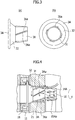
- FIG. 1 illustrates an electric motor with a gear reducer that is one type of dynamoelectric machine with a gear reducer according to the present invention, in which an inside of the gear reducer is not shown.
- FIG. 2 illustrates a grease blocking member mounted on an electric motor output shaft.
- FIGs. 3(a) and 3(b) are magnified views of the grease blocking member.
- the electric motor includes an electric motor main body 1, a gear reducer main body 2 that is assembled with the electric motor main body 1, and an electric motor case 10 constituting the electric motor main body 1, and a bracket 11 is provided, which is press-fitted on one opening end of the electric motor case 10.
- a gear case 20 of the gear reducer main body 2 is fitted with the bracket 11 on its protruding end, and the electric motor case 10 and the gear case 20 are integrally fastened with bolts, not shown in the drawings.
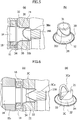
- a rotator 13 is concentrically arranged on an axis of a stator 12, and the rotator 13 is rotatably supported on both ends of a rotational shaft 14 via bearings 15 1 , 15 2 .
- one end of the rotational shaft 14 is delivered outward from an open hole 11a of the bracket 11, and thereby an electric motor output shaft 14A is constituted.
- the electric motor output shaft 14A is provided with helically cut gear teeth 16, and a portion 17 with the helically cut gear teeth 16 is inserted into the gear case 20 of the gear reducer main body 2 through a hole 21a of a gear reducer flange 21 to be engaged with a helical gear 22 arranged inside the gear case 20.
- An oil seal 18 is a single lip oil seal arranged on an inner periphery surface of the open hole 11a of the bracket 11.
- a grease blocking member 3A is a member for preventing leakage of grease, which is mounted by press-fitting onto the electric motor output shaft 14A at a location closer to the base end of the shaft than the portion 17 with the helically cut gear teeth 16.
- the grease blocking member 3A is constituted by a cylindrical portion 31 and an expansion portion 32, which is provided so as to form a shape of a horn in which the diameter gradually increases from one end of the cylindrical portion 31.
- a plurality of linear protrusions 31a is provided at a reverse angle from the helically cut gear teeth 16 in a leading edge portion of the electric motor output shaft 14A.
- a wall surface portion 3Aa of the protrusions 31a is formed in a direction perpendicular to the helically cut gear teeth 16 so as to block the grease flowing in and coming along the surface of the helically cut gear teeth 16 provided in the leading edge portion of the electric motor output shaft 14A.
- the grease blocking member 3A is produced by die casting of aluminium or resin molding of silicon performed so that a plurality of linear protrusions 31a is provided at a reverse angle from the helically cut gear teeth 16 provided in the leading edge portion of the electric motor output shaft 14A. In mounting the grease blocking member 3A, the grease blocking member 3A is assembled with the electric motor output shaft 14A by press-fitting except for a portion 16b for engagement with the helical gear 22 of the reducer.
- the grease blocking member 3A for preventing inflow of the grease into the electric motor is press-fitted to be engaged with the electric motor output shaft 14A on a terminal end of the shaft by detouring around the engagement portion 16b of the electric motor output shaft 14A, and the protrusions 31a of the grease blocking member 3A are arranged in the direction perpendicular to the helically cut gear teeth 16.
- the wall surface portion 3Aa for blocking inflow of the grease is provided on the front side of the protrusions 31a of the grease blocking member 3A.
- the grease blocking member 3A is provided with a plurality of linear protrusions 31a that are formed in the reverse angle from the helically cut gear teeth 16 provided in the leading edge portion of the electric motor output shaft 14A, an action for forcing back the grease flowing out to the side of the electric motor due to the helically cut gear teeth 16 of the electric motor output shaft 14A toward the gear reducer is caused by the wall surface portion 3Aa as the linear protrusions 31a provided at the reverse angle from the helically cut gear teeth turn. With this configuration, leakage of the grease flowing out from inside the reducer via the gear reducer flange 21 to the side of the electric motor can be prevented.
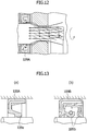
- FIGs. 5(a) and 5(b) illustrate an embodiment of the grease blocking member 3 of the present invention, in which the same portions and components as those illustrated in FIGs. 3 and 4 are provided with the same reference symbols and numerals.
- a grease blocking member 3B is provided with V-shaped or U-shaped protrusions 31b formed on the cylindrical portion 31 at two locations.
- the grease blocking member 3B is used, in which V-shaped or U-shaped protrusions 31b are provided in the cylindrical portion 31 at two or more locations, instead of the grease blocking member 3A.
- V-shaped protrusions 31b are provided in the cylindrical portion 31 at two or more locations, instead of the grease blocking member 3A.
- the leaked grease can be forced back by a wall surface portion 3Ba of the protrusions 31b provided at the reverse angle from the helically cut gear teeth as the grease blocking member 3B turns.
- the protrusions 31b may be provided at more than two locations.
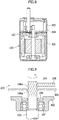
- FIGs. 6(a) and 6(b) also illustrate another embodiment of the grease blocking member 3 of the present invention, in which the same portions and components as those illustrated in FIGs. 3 and 4 are provided with the same reference symbols and numerals.
- a grease blocking member 3C is provided with U-shaped cut portions 33 at two locations in the leading edge portion from the cylindrical portion 31 to the expansion portion 32.
- the grease blocking member 3C is used in which the cut portions 33 are provided at two or more locations that cut the leading edge portion of the grease blocking member 3C in the V-like or U-like shape.
- the cut portions 33 formed in the leading edge portion of the grease blocking member 3C infiltration of grease can be prevented by a wall surface portion 3Ca of the cut portions 33 provided at the reverse angle from the helically cut gear teeth, and similarly to the example that uses the grease blocking member 3B, grease accumulated in the cut portions 33 provided in the leading edge portion of the grease blocking member 3C can be forced back by the wall surface portion 3Ca toward the gear reducer as the grease blocking member 3C turns.
- the cut portions are provided at two locations; however, alternatively, the cut portion may provided at one location only (in this case, the cut portion is diagonally cut) or may be provided at more than two locations according to the diameter of the shaft of the electric motor output shaft.
- the grease blocking member 3C may be press-fitted to the electric motor output shaft 14A, and a labyrinth structure (flange portion) 34 which covers a lip portion of the oil seal 18 may be provided to the grease blocking member 3C at a location on the side of the electric motor. With this configuration, intrusion of grease into the electric motor can be absolutely blocked.
- FIGs. 7(a) and 7(b) illustrate a modification of the example illustrated in FIGs. 6(a) and 6(b) , in which the same portions and components as those in FIGs. 6(a) and 6(b) are provided with the same reference symbols and numerals and descriptions thereof are omitted below.
- a grease blocking member 3D is formed, in which the cut portions 33 formed in the leading edge portion of the cylindrical portion 31 in the axial direction are cut diagonally in relation to the axial direction, so that the sections thereof face outward to allow a wall surface 3Da formed by the sections to be viewed from a lateral direction.
- the present invention is not limited to the embodiments described above, and various shapes can be applied as the shape of the grease blocking member 3, 3A, 3B, 3C, 3D, for example, and the grease blocking member can take any shape such as the shape of the linear protrusions 31a, the V-shaped protrusions 31b, and the cut portions 33 if the grease blocking member is capable of inhibiting inflow of the grease, and the present invention can of course be appropriately modified or altered within a range that does not change the technical scope of the present invention.
- examples of the electric motors are described, and the present invention can be applied to a dynamoelectric machine provided with an output shaft that engages with a gear at an input port of the gear reducer.
- a dynamoelectric machine includes dynamos, generators, and the like, and also includes clutch brakes, electromagnetic brakes, torque limiters, intermediate reducers, and the like, which are arranged between the electric motor and the gear reducer and configured to transmit the rotation of the output shaft of the electric motor to the gear reducer.
Landscapes
- Engineering & Computer Science (AREA)
- General Engineering & Computer Science (AREA)
- Mechanical Engineering (AREA)
- Power Engineering (AREA)
- General Details Of Gearings (AREA)
- Connection Of Motors, Electrical Generators, Mechanical Devices, And The Like (AREA)
- Motor Or Generator Frames (AREA)
- Sealing Of Bearings (AREA)
- Gear Transmission (AREA)
- Sealing Using Fluids, Sealing Without Contact, And Removal Of Oil (AREA)
- Gasket Seals (AREA)
Claims (1)
- Struktur zum Verhindern von Fettaustritt für ein Untersetzungsgetriebe einer dynamoelektrischen Maschine mit dem Untersetzungsgetriebe, bei der eine Verzahnung in einem Vorderkantenabschnitt einer Abtriebswelle (14A) einer dynamoelektrischen Maschine vorgesehen ist, der Vorderkantenabschnitt der Abtriebswelle (14A) der dynamoelektrischen Maschine in ein Gehäuse (20) eines Untersetzungsgetriebes über eine Eingangsöffnung des Untersetzungsgetriebes eingeführt ist und die Abtriebswelle (14A) der dynamoelektrischen Maschine mit der Verzahnung in ein im Inneren des Gehäuses (20) des Untersetzungsgetriebes angeordneten Zahnrad eingreift,
dadurch gekennzeichnet, dass ein Fettblockierelement (3D) zum Verhindern des Eintritts von Fett in die dynamoelektrische Maschine um die Abtriebswelle (14A) der dynamoelektrischen Maschine herum vorgesehen ist, wobei das Fettblockierelement (3D) durch einen zylindrischen Abschnitt (31) und einen Aufweitungsabschnitt (32) gebildet wird; und dadurch gekennzeichnet, dass
das Fettblockierelement (3D) durch Presspassung an einem Abschlussende eines Eingriffsabschnitts (16b) der Abtriebswelle (14A) der dynamoelektrischen Maschine montiert ist und das Eintreten von Fett in die dynamoelektrische Maschine verhindert;V-förmige oder U-förmige ausgeschnittene Abschnitte (33) an zwei oder mehr Stellen in dem zylindrischen Abschnitt (31) so vorgesehen sind, dass sie sich zu dem Aufweitungsabschnitt (32) erstrecken; unddie ausgeschnittenen Abschnitte (33) diagonal entlang der axialen Richtung so ausgeschnitten sind, dass deren Ausschnitte nach außen zeigen, um zu ermöglichen, dass eine durch die Ausschnitte gebildete Wandfläche (3Da) nach außen zeigt, das Fettblockierelement mit einem Flanschabschnitt (34) versehen ist, der an einem Basisende des Aufweitungsabschnitts (32) vorgesehen ist;der Aufweitungsabschnitt (32) als ein konischer Abschnitt ausgebildet ist, der zwischen dem zylindrischen Abschnitt (31) und dem Flanschabschnitt (34) vorgesehen ist und einen Durchmesser aufweist, der sich von dem zylindrischen Abschnitt aus allmählich aufweitet,
das Fettblockierelement aus Aluminium besteht und durch Presspassung an der Abtriebswelle der dynamoelektrischen Maschine (14A) montiert ist, und
eine schrägverzahnte Verzahnung als Verzahnung im Vorderkantenabschnitt der Abtriebswelle der dynamoelektrischen Maschine (14A) vorgesehen ist.
Applications Claiming Priority (3)
| Application Number | Priority Date | Filing Date | Title |
|---|---|---|---|
| JP2013025484A JP5787915B2 (ja) | 2013-02-13 | 2013-02-13 | 歯車減速機付電動機における歯車減速機のグリース漏れ防止構造 |
| PCT/JP2014/050509 WO2014125855A1 (ja) | 2013-02-13 | 2014-01-15 | 歯車減速機のグリース漏れ防止構造 |
| EP14752120.7A EP2957797B1 (de) | 2013-02-13 | 2014-01-15 | Struktur zur vermeidung von schmiermittelundichtigkeiten in einem untersetzungsgetriebe |
Related Parent Applications (2)
| Application Number | Title | Priority Date | Filing Date |
|---|---|---|---|
| EP14752120.7A Division EP2957797B1 (de) | 2013-02-13 | 2014-01-15 | Struktur zur vermeidung von schmiermittelundichtigkeiten in einem untersetzungsgetriebe |
| EP14752120.7A Division-Into EP2957797B1 (de) | 2013-02-13 | 2014-01-15 | Struktur zur vermeidung von schmiermittelundichtigkeiten in einem untersetzungsgetriebe |
Publications (2)
| Publication Number | Publication Date |
|---|---|
| EP3388720A1 EP3388720A1 (de) | 2018-10-17 |
| EP3388720B1 true EP3388720B1 (de) | 2020-03-04 |
Family
ID=51353866
Family Applications (2)
| Application Number | Title | Priority Date | Filing Date |
|---|---|---|---|
| EP14752120.7A Active EP2957797B1 (de) | 2013-02-13 | 2014-01-15 | Struktur zur vermeidung von schmiermittelundichtigkeiten in einem untersetzungsgetriebe |
| EP18174191.9A Active EP3388720B1 (de) | 2013-02-13 | 2014-01-15 | Struktur zur vermeidung von schmiermittelundichtigkeiten in einem untersetzungsgetriebe |
Family Applications Before (1)
| Application Number | Title | Priority Date | Filing Date |
|---|---|---|---|
| EP14752120.7A Active EP2957797B1 (de) | 2013-02-13 | 2014-01-15 | Struktur zur vermeidung von schmiermittelundichtigkeiten in einem untersetzungsgetriebe |
Country Status (8)
| Country | Link |
|---|---|
| US (1) | US9391482B2 (de) |
| EP (2) | EP2957797B1 (de) |
| JP (2) | JP5787915B2 (de) |
| KR (2) | KR101618648B1 (de) |
| CN (1) | CN105051433B (de) |
| ES (1) | ES2701204T3 (de) |
| TW (1) | TWI546478B (de) |
| WO (1) | WO2014125855A1 (de) |
Families Citing this family (7)
| Publication number | Priority date | Publication date | Assignee | Title |
|---|---|---|---|---|
| KR101703614B1 (ko) * | 2015-09-10 | 2017-02-07 | 현대자동차 주식회사 | 구동모터와 감속기의 연결 구조 |
| CN111219446B (zh) * | 2018-11-27 | 2023-01-17 | 富田电机股份有限公司 | 电动机车的整合式动力模组 |
| ES2875346T3 (es) * | 2018-12-05 | 2021-11-10 | Fukuta Electric & Machinery Co Ltd | Módulo de potencia integrado de patinete eléctrico |
| JP7272216B2 (ja) * | 2019-07-26 | 2023-05-12 | 株式会社デンソー | クラッチ装置 |
| JP2021080940A (ja) * | 2019-11-14 | 2021-05-27 | Nok株式会社 | 密封機構 |
| CN111503254B (zh) * | 2020-04-29 | 2023-04-07 | 株洲齿轮有限责任公司 | 一种减速器电机配合止口腔漏油查验装置 |
| EP4302926B1 (de) | 2022-06-16 | 2025-08-06 | Milwaukee Electric Tool Corporation | Kompaktes schlagwerkzeug |
Family Cites Families (22)
| Publication number | Priority date | Publication date | Assignee | Title |
|---|---|---|---|---|
| JPS5438759U (de) * | 1977-08-24 | 1979-03-14 | ||
| JPS5438759A (en) | 1977-09-02 | 1979-03-23 | Toshiba Corp | Forming method for fluorescent screen of color picture tube |
| JPS55181466U (de) * | 1979-06-13 | 1980-12-26 | ||
| JPS589056U (ja) * | 1981-07-10 | 1983-01-20 | 三菱電機株式会社 | 可変速減速電動機 |
| CH658707A5 (de) | 1982-11-05 | 1986-11-28 | Inventio Ag | Beruehrungsfreie dichtung. |
| JPH0648210Y2 (ja) | 1988-09-02 | 1994-12-12 | オリエンタルモーター株式会社 | ギヤヘッド付モータにおけるギヤヘッドのグリスシール構造 |
| DE3916495A1 (de) | 1989-05-20 | 1990-11-22 | Bosch Gmbh Robert | Handwerkzeug mit einem getriebegehaeuse mit dichtring |
| JPH0545293U (ja) * | 1991-11-22 | 1993-06-18 | 株式会社小松製作所 | 減速機の潤滑機構 |
| JPH0648210A (ja) | 1992-07-31 | 1994-02-22 | Yanmar Agricult Equip Co Ltd | 乗用農作業機 |
| TW265395B (de) * | 1993-03-18 | 1995-12-11 | Warman Int Ltd | |
| JP3122345B2 (ja) | 1995-09-06 | 2001-01-09 | 日機装株式会社 | 歯車式減速機 |
| JPH1193877A (ja) * | 1997-09-25 | 1999-04-06 | Nec Yamagata Ltd | 真空ポンプ |
| US6000140A (en) * | 1997-12-01 | 1999-12-14 | Black & Decker Inc. | Power tool with lubricating system |
| JP3963621B2 (ja) | 1999-11-16 | 2007-08-22 | 住友重機械工業株式会社 | 内接噛合遊星歯車構造の減速機のフランジ面の封止構造 |
| CN2442035Y (zh) * | 2000-03-13 | 2001-08-08 | 贾建新 | 叶片式机械密封盘 |
| US6578850B1 (en) * | 2000-11-14 | 2003-06-17 | General Electric Company | Dynamic seal for a drive shaft |
| JP2007154998A (ja) | 2005-12-05 | 2007-06-21 | Oriental Motor Co Ltd | 歯車減速機付電動機のグリース漏れ防止構造 |
| DE102006000469A1 (de) * | 2006-09-20 | 2008-04-03 | Hilti Ag | Wellenlagerdichtung |
| US20080196523A1 (en) * | 2007-02-16 | 2008-08-21 | Chia-Min Liu | Dustproof Device for a Ball Screw |
| JP2008236903A (ja) | 2007-03-20 | 2008-10-02 | Denso Corp | 電動機 |
| JP2008259368A (ja) * | 2007-04-06 | 2008-10-23 | Shinano Kenshi Co Ltd | 回転機 |
| JP5154364B2 (ja) | 2008-10-24 | 2013-02-27 | 株式会社マキタ | ギヤ室のシール構造 |
-
2013
- 2013-02-13 JP JP2013025484A patent/JP5787915B2/ja active Active
-
2014
- 2014-01-15 KR KR1020157019580A patent/KR101618648B1/ko active Active
- 2014-01-15 US US14/762,734 patent/US9391482B2/en active Active
- 2014-01-15 KR KR1020167004249A patent/KR101800687B1/ko active Active
- 2014-01-15 WO PCT/JP2014/050509 patent/WO2014125855A1/ja not_active Ceased
- 2014-01-15 CN CN201480004692.5A patent/CN105051433B/zh active Active
- 2014-01-15 JP JP2015500160A patent/JP6077096B2/ja active Active
- 2014-01-15 EP EP14752120.7A patent/EP2957797B1/de active Active
- 2014-01-15 EP EP18174191.9A patent/EP3388720B1/de active Active
- 2014-01-15 ES ES14752120T patent/ES2701204T3/es active Active
- 2014-02-06 TW TW103103920A patent/TWI546478B/zh active
Non-Patent Citations (1)
| Title |
|---|
| None * |
Also Published As
| Publication number | Publication date |
|---|---|
| JP2014152910A (ja) | 2014-08-25 |
| CN105051433A (zh) | 2015-11-11 |
| EP3388720A1 (de) | 2018-10-17 |
| KR20150089095A (ko) | 2015-08-04 |
| EP2957797A1 (de) | 2015-12-23 |
| US9391482B2 (en) | 2016-07-12 |
| KR101618648B1 (ko) | 2016-05-09 |
| JP6077096B2 (ja) | 2017-02-08 |
| US20150372556A1 (en) | 2015-12-24 |
| TW201441514A (zh) | 2014-11-01 |
| JP5787915B2 (ja) | 2015-09-30 |
| KR101800687B1 (ko) | 2017-11-23 |
| CN105051433B (zh) | 2017-08-11 |
| EP2957797B1 (de) | 2018-11-14 |
| ES2701204T3 (es) | 2019-02-21 |
| EP2957797A4 (de) | 2016-02-24 |
| JPWO2014125855A1 (ja) | 2017-02-02 |
| KR20160027220A (ko) | 2016-03-09 |
| WO2014125855A1 (ja) | 2014-08-21 |
| TWI546478B (zh) | 2016-08-21 |
Similar Documents
| Publication | Publication Date | Title |
|---|---|---|
| EP3388720B1 (de) | Struktur zur vermeidung von schmiermittelundichtigkeiten in einem untersetzungsgetriebe | |
| CN101290063A (zh) | 车辆传动装置 | |
| JP4789310B2 (ja) | 水中モータにおけるステータコアの回り止め構造 | |
| JP2010025138A (ja) | 密封装置 | |
| EP2728715A2 (de) | Rotierende elektrische Maschine | |
| KR102487166B1 (ko) | 모터의 레졸버 장착 구조 | |
| CN103573828B (zh) | 挡油环 | |
| US8777595B2 (en) | Rotary piston engine | |
| KR101786197B1 (ko) | 감속기 일체형 모터 | |
| JP5529719B2 (ja) | 回転電機 | |
| JP2015072034A (ja) | 転がり軸受 | |
| US10024364B2 (en) | Integrated plastic shield bearing assembly | |
| JP2019149859A (ja) | 磁石冷却構造および回転電機 | |
| EP3913262A1 (de) | Ringdichtung und roboter | |
| JP2017223319A (ja) | シール部材及びモータ | |
| JP4949979B2 (ja) | 減速機 | |
| CN102195386A (zh) | 旋转电机 | |
| JP5757082B2 (ja) | 電動ポンプ | |
| JP2011142786A (ja) | モータの冷却装置 | |
| JP2024094798A (ja) | インホイールモータ駆動装置 | |
| JP2019035417A (ja) | シール機構 | |
| JP5651999B2 (ja) | ダイレクトドライブモータ、インデックステーブル及び位置決め装置 | |
| WO2021095344A1 (ja) | モータ及びそれを備えた電気機器 | |
| JP2020094656A (ja) | 車両駆動装置 | |
| KR20190072218A (ko) | 척력을 이용한 축력감쇄부재와 이를 포함하는 토크컨버터 |
Legal Events
| Date | Code | Title | Description |
|---|---|---|---|
| PUAI | Public reference made under article 153(3) epc to a published international application that has entered the european phase |
Free format text: ORIGINAL CODE: 0009012 |
|
| STAA | Information on the status of an ep patent application or granted ep patent |
Free format text: STATUS: THE APPLICATION HAS BEEN PUBLISHED |
|
| AC | Divisional application: reference to earlier application |
Ref document number: 2957797 Country of ref document: EP Kind code of ref document: P |
|
| AK | Designated contracting states |
Kind code of ref document: A1 Designated state(s): AL AT BE BG CH CY CZ DE DK EE ES FI FR GB GR HR HU IE IS IT LI LT LU LV MC MK MT NL NO PL PT RO RS SE SI SK SM TR |
|
| STAA | Information on the status of an ep patent application or granted ep patent |
Free format text: STATUS: REQUEST FOR EXAMINATION WAS MADE |
|
| 17P | Request for examination filed |
Effective date: 20181101 |
|
| RBV | Designated contracting states (corrected) |
Designated state(s): AL AT BE BG CH CY CZ DE DK EE ES FI FR GB GR HR HU IE IS IT LI LT LU LV MC MK MT NL NO PL PT RO RS SE SI SK SM TR |
|
| STAA | Information on the status of an ep patent application or granted ep patent |
Free format text: STATUS: EXAMINATION IS IN PROGRESS |
|
| 17Q | First examination report despatched |
Effective date: 20190225 |
|
| GRAP | Despatch of communication of intention to grant a patent |
Free format text: ORIGINAL CODE: EPIDOSNIGR1 |
|
| STAA | Information on the status of an ep patent application or granted ep patent |
Free format text: STATUS: GRANT OF PATENT IS INTENDED |
|
| INTG | Intention to grant announced |
Effective date: 20191202 |
|
| GRAS | Grant fee paid |
Free format text: ORIGINAL CODE: EPIDOSNIGR3 |
|
| GRAA | (expected) grant |
Free format text: ORIGINAL CODE: 0009210 |
|
| STAA | Information on the status of an ep patent application or granted ep patent |
Free format text: STATUS: THE PATENT HAS BEEN GRANTED |
|
| AC | Divisional application: reference to earlier application |
Ref document number: 2957797 Country of ref document: EP Kind code of ref document: P |
|
| AK | Designated contracting states |
Kind code of ref document: B1 Designated state(s): AL AT BE BG CH CY CZ DE DK EE ES FI FR GB GR HR HU IE IS IT LI LT LU LV MC MK MT NL NO PL PT RO RS SE SI SK SM TR |
|
| REG | Reference to a national code |
Ref country code: GB Ref legal event code: FG4D |
|
| REG | Reference to a national code |
Ref country code: CH Ref legal event code: EP |
|
| REG | Reference to a national code |
Ref country code: AT Ref legal event code: REF Ref document number: 1240758 Country of ref document: AT Kind code of ref document: T Effective date: 20200315 |
|
| REG | Reference to a national code |
Ref country code: DE Ref legal event code: R096 Ref document number: 602014062042 Country of ref document: DE |
|
| REG | Reference to a national code |
Ref country code: IE Ref legal event code: FG4D |
|
| PG25 | Lapsed in a contracting state [announced via postgrant information from national office to epo] |
Ref country code: NO Free format text: LAPSE BECAUSE OF FAILURE TO SUBMIT A TRANSLATION OF THE DESCRIPTION OR TO PAY THE FEE WITHIN THE PRESCRIBED TIME-LIMIT Effective date: 20200604 Ref country code: FI Free format text: LAPSE BECAUSE OF FAILURE TO SUBMIT A TRANSLATION OF THE DESCRIPTION OR TO PAY THE FEE WITHIN THE PRESCRIBED TIME-LIMIT Effective date: 20200304 Ref country code: RS Free format text: LAPSE BECAUSE OF FAILURE TO SUBMIT A TRANSLATION OF THE DESCRIPTION OR TO PAY THE FEE WITHIN THE PRESCRIBED TIME-LIMIT Effective date: 20200304 |
|
| REG | Reference to a national code |
Ref country code: NL Ref legal event code: MP Effective date: 20200304 |
|
| PG25 | Lapsed in a contracting state [announced via postgrant information from national office to epo] |
Ref country code: GR Free format text: LAPSE BECAUSE OF FAILURE TO SUBMIT A TRANSLATION OF THE DESCRIPTION OR TO PAY THE FEE WITHIN THE PRESCRIBED TIME-LIMIT Effective date: 20200605 Ref country code: HR Free format text: LAPSE BECAUSE OF FAILURE TO SUBMIT A TRANSLATION OF THE DESCRIPTION OR TO PAY THE FEE WITHIN THE PRESCRIBED TIME-LIMIT Effective date: 20200304 Ref country code: BG Free format text: LAPSE BECAUSE OF FAILURE TO SUBMIT A TRANSLATION OF THE DESCRIPTION OR TO PAY THE FEE WITHIN THE PRESCRIBED TIME-LIMIT Effective date: 20200604 Ref country code: SE Free format text: LAPSE BECAUSE OF FAILURE TO SUBMIT A TRANSLATION OF THE DESCRIPTION OR TO PAY THE FEE WITHIN THE PRESCRIBED TIME-LIMIT Effective date: 20200304 Ref country code: LV Free format text: LAPSE BECAUSE OF FAILURE TO SUBMIT A TRANSLATION OF THE DESCRIPTION OR TO PAY THE FEE WITHIN THE PRESCRIBED TIME-LIMIT Effective date: 20200304 |
|
| REG | Reference to a national code |
Ref country code: LT Ref legal event code: MG4D |
|
| PG25 | Lapsed in a contracting state [announced via postgrant information from national office to epo] |
Ref country code: NL Free format text: LAPSE BECAUSE OF FAILURE TO SUBMIT A TRANSLATION OF THE DESCRIPTION OR TO PAY THE FEE WITHIN THE PRESCRIBED TIME-LIMIT Effective date: 20200304 |
|
| PG25 | Lapsed in a contracting state [announced via postgrant information from national office to epo] |
Ref country code: CZ Free format text: LAPSE BECAUSE OF FAILURE TO SUBMIT A TRANSLATION OF THE DESCRIPTION OR TO PAY THE FEE WITHIN THE PRESCRIBED TIME-LIMIT Effective date: 20200304 Ref country code: LT Free format text: LAPSE BECAUSE OF FAILURE TO SUBMIT A TRANSLATION OF THE DESCRIPTION OR TO PAY THE FEE WITHIN THE PRESCRIBED TIME-LIMIT Effective date: 20200304 Ref country code: PT Free format text: LAPSE BECAUSE OF FAILURE TO SUBMIT A TRANSLATION OF THE DESCRIPTION OR TO PAY THE FEE WITHIN THE PRESCRIBED TIME-LIMIT Effective date: 20200729 Ref country code: ES Free format text: LAPSE BECAUSE OF FAILURE TO SUBMIT A TRANSLATION OF THE DESCRIPTION OR TO PAY THE FEE WITHIN THE PRESCRIBED TIME-LIMIT Effective date: 20200304 Ref country code: EE Free format text: LAPSE BECAUSE OF FAILURE TO SUBMIT A TRANSLATION OF THE DESCRIPTION OR TO PAY THE FEE WITHIN THE PRESCRIBED TIME-LIMIT Effective date: 20200304 Ref country code: SM Free format text: LAPSE BECAUSE OF FAILURE TO SUBMIT A TRANSLATION OF THE DESCRIPTION OR TO PAY THE FEE WITHIN THE PRESCRIBED TIME-LIMIT Effective date: 20200304 Ref country code: SK Free format text: LAPSE BECAUSE OF FAILURE TO SUBMIT A TRANSLATION OF THE DESCRIPTION OR TO PAY THE FEE WITHIN THE PRESCRIBED TIME-LIMIT Effective date: 20200304 Ref country code: RO Free format text: LAPSE BECAUSE OF FAILURE TO SUBMIT A TRANSLATION OF THE DESCRIPTION OR TO PAY THE FEE WITHIN THE PRESCRIBED TIME-LIMIT Effective date: 20200304 Ref country code: IS Free format text: LAPSE BECAUSE OF FAILURE TO SUBMIT A TRANSLATION OF THE DESCRIPTION OR TO PAY THE FEE WITHIN THE PRESCRIBED TIME-LIMIT Effective date: 20200704 |
|
| REG | Reference to a national code |
Ref country code: AT Ref legal event code: MK05 Ref document number: 1240758 Country of ref document: AT Kind code of ref document: T Effective date: 20200304 |
|
| REG | Reference to a national code |
Ref country code: DE Ref legal event code: R097 Ref document number: 602014062042 Country of ref document: DE |
|
| PLBE | No opposition filed within time limit |
Free format text: ORIGINAL CODE: 0009261 |
|
| STAA | Information on the status of an ep patent application or granted ep patent |
Free format text: STATUS: NO OPPOSITION FILED WITHIN TIME LIMIT |
|
| PG25 | Lapsed in a contracting state [announced via postgrant information from national office to epo] |
Ref country code: IT Free format text: LAPSE BECAUSE OF FAILURE TO SUBMIT A TRANSLATION OF THE DESCRIPTION OR TO PAY THE FEE WITHIN THE PRESCRIBED TIME-LIMIT Effective date: 20200304 Ref country code: AT Free format text: LAPSE BECAUSE OF FAILURE TO SUBMIT A TRANSLATION OF THE DESCRIPTION OR TO PAY THE FEE WITHIN THE PRESCRIBED TIME-LIMIT Effective date: 20200304 Ref country code: DK Free format text: LAPSE BECAUSE OF FAILURE TO SUBMIT A TRANSLATION OF THE DESCRIPTION OR TO PAY THE FEE WITHIN THE PRESCRIBED TIME-LIMIT Effective date: 20200304 |
|
| 26N | No opposition filed |
Effective date: 20201207 |
|
| PG25 | Lapsed in a contracting state [announced via postgrant information from national office to epo] |
Ref country code: PL Free format text: LAPSE BECAUSE OF FAILURE TO SUBMIT A TRANSLATION OF THE DESCRIPTION OR TO PAY THE FEE WITHIN THE PRESCRIBED TIME-LIMIT Effective date: 20200304 Ref country code: SI Free format text: LAPSE BECAUSE OF FAILURE TO SUBMIT A TRANSLATION OF THE DESCRIPTION OR TO PAY THE FEE WITHIN THE PRESCRIBED TIME-LIMIT Effective date: 20200304 |
|
| PG25 | Lapsed in a contracting state [announced via postgrant information from national office to epo] |
Ref country code: MC Free format text: LAPSE BECAUSE OF FAILURE TO SUBMIT A TRANSLATION OF THE DESCRIPTION OR TO PAY THE FEE WITHIN THE PRESCRIBED TIME-LIMIT Effective date: 20200304 |
|
| REG | Reference to a national code |
Ref country code: CH Ref legal event code: PL |
|
| PG25 | Lapsed in a contracting state [announced via postgrant information from national office to epo] |
Ref country code: LU Free format text: LAPSE BECAUSE OF NON-PAYMENT OF DUE FEES Effective date: 20210115 |
|
| REG | Reference to a national code |
Ref country code: BE Ref legal event code: MM Effective date: 20210131 |
|
| PG25 | Lapsed in a contracting state [announced via postgrant information from national office to epo] |
Ref country code: LI Free format text: LAPSE BECAUSE OF NON-PAYMENT OF DUE FEES Effective date: 20210131 Ref country code: CH Free format text: LAPSE BECAUSE OF NON-PAYMENT OF DUE FEES Effective date: 20210131 |
|
| PG25 | Lapsed in a contracting state [announced via postgrant information from national office to epo] |
Ref country code: IE Free format text: LAPSE BECAUSE OF NON-PAYMENT OF DUE FEES Effective date: 20210115 |
|
| PG25 | Lapsed in a contracting state [announced via postgrant information from national office to epo] |
Ref country code: BE Free format text: LAPSE BECAUSE OF NON-PAYMENT OF DUE FEES Effective date: 20210131 |
|
| PG25 | Lapsed in a contracting state [announced via postgrant information from national office to epo] |
Ref country code: CY Free format text: LAPSE BECAUSE OF FAILURE TO SUBMIT A TRANSLATION OF THE DESCRIPTION OR TO PAY THE FEE WITHIN THE PRESCRIBED TIME-LIMIT Effective date: 20200304 |
|
| PG25 | Lapsed in a contracting state [announced via postgrant information from national office to epo] |
Ref country code: HU Free format text: LAPSE BECAUSE OF FAILURE TO SUBMIT A TRANSLATION OF THE DESCRIPTION OR TO PAY THE FEE WITHIN THE PRESCRIBED TIME-LIMIT; INVALID AB INITIO Effective date: 20140115 |
|
| PG25 | Lapsed in a contracting state [announced via postgrant information from national office to epo] |
Ref country code: MK Free format text: LAPSE BECAUSE OF FAILURE TO SUBMIT A TRANSLATION OF THE DESCRIPTION OR TO PAY THE FEE WITHIN THE PRESCRIBED TIME-LIMIT Effective date: 20200304 |
|
| PG25 | Lapsed in a contracting state [announced via postgrant information from national office to epo] |
Ref country code: MT Free format text: LAPSE BECAUSE OF FAILURE TO SUBMIT A TRANSLATION OF THE DESCRIPTION OR TO PAY THE FEE WITHIN THE PRESCRIBED TIME-LIMIT Effective date: 20200304 |
|
| PGFP | Annual fee paid to national office [announced via postgrant information from national office to epo] |
Ref country code: DE Payment date: 20250121 Year of fee payment: 12 |
|
| PGFP | Annual fee paid to national office [announced via postgrant information from national office to epo] |
Ref country code: FR Payment date: 20250127 Year of fee payment: 12 |
|
| PGFP | Annual fee paid to national office [announced via postgrant information from national office to epo] |
Ref country code: GB Payment date: 20250128 Year of fee payment: 12 |
|
| PG25 | Lapsed in a contracting state [announced via postgrant information from national office to epo] |
Ref country code: TR Free format text: LAPSE BECAUSE OF FAILURE TO SUBMIT A TRANSLATION OF THE DESCRIPTION OR TO PAY THE FEE WITHIN THE PRESCRIBED TIME-LIMIT Effective date: 20200304 |