EP3376529B1 - Robot transport device - Google Patents
Robot transport device Download PDFInfo
- Publication number
- EP3376529B1 EP3376529B1 EP16864049.8A EP16864049A EP3376529B1 EP 3376529 B1 EP3376529 B1 EP 3376529B1 EP 16864049 A EP16864049 A EP 16864049A EP 3376529 B1 EP3376529 B1 EP 3376529B1
- Authority
- EP
- European Patent Office
- Prior art keywords
- transportation space
- robot
- space
- circulation passages
- transport device
- Prior art date
- Legal status (The legal status is an assumption and is not a legal conclusion. Google has not performed a legal analysis and makes no representation as to the accuracy of the status listed.)
- Active
Links
- 239000000428 dust Substances 0.000 claims description 8
- 239000007789 gas Substances 0.000 description 32
- 235000012431 wafers Nutrition 0.000 description 7
- 239000004065 semiconductor Substances 0.000 description 5
- 239000004973 liquid crystal related substance Substances 0.000 description 4
- 239000011261 inert gas Substances 0.000 description 3
- 238000012258 culturing Methods 0.000 description 2
- 230000003247 decreasing effect Effects 0.000 description 2
- 230000000694 effects Effects 0.000 description 1
- 230000005611 electricity Effects 0.000 description 1
- 230000001954 sterilising effect Effects 0.000 description 1
- 239000000758 substrate Substances 0.000 description 1
Images
Classifications
-
- H—ELECTRICITY
- H01—ELECTRIC ELEMENTS
- H01L—SEMICONDUCTOR DEVICES NOT COVERED BY CLASS H10
- H01L21/00—Processes or apparatus adapted for the manufacture or treatment of semiconductor or solid state devices or of parts thereof
- H01L21/67—Apparatus specially adapted for handling semiconductor or electric solid state devices during manufacture or treatment thereof; Apparatus specially adapted for handling wafers during manufacture or treatment of semiconductor or electric solid state devices or components ; Apparatus not specifically provided for elsewhere
- H01L21/677—Apparatus specially adapted for handling semiconductor or electric solid state devices during manufacture or treatment thereof; Apparatus specially adapted for handling wafers during manufacture or treatment of semiconductor or electric solid state devices or components ; Apparatus not specifically provided for elsewhere for conveying, e.g. between different workstations
- H01L21/67739—Apparatus specially adapted for handling semiconductor or electric solid state devices during manufacture or treatment thereof; Apparatus specially adapted for handling wafers during manufacture or treatment of semiconductor or electric solid state devices or components ; Apparatus not specifically provided for elsewhere for conveying, e.g. between different workstations into and out of processing chamber
- H01L21/67742—Mechanical parts of transfer devices
-
- B—PERFORMING OPERATIONS; TRANSPORTING
- B25—HAND TOOLS; PORTABLE POWER-DRIVEN TOOLS; MANIPULATORS
- B25J—MANIPULATORS; CHAMBERS PROVIDED WITH MANIPULATION DEVICES
- B25J15/00—Gripping heads and other end effectors
-
- B—PERFORMING OPERATIONS; TRANSPORTING
- B25—HAND TOOLS; PORTABLE POWER-DRIVEN TOOLS; MANIPULATORS
- B25J—MANIPULATORS; CHAMBERS PROVIDED WITH MANIPULATION DEVICES
- B25J5/00—Manipulators mounted on wheels or on carriages
- B25J5/005—Manipulators mounted on wheels or on carriages mounted on endless tracks or belts
-
- B—PERFORMING OPERATIONS; TRANSPORTING
- B65—CONVEYING; PACKING; STORING; HANDLING THIN OR FILAMENTARY MATERIAL
- B65G—TRANSPORT OR STORAGE DEVICES, e.g. CONVEYORS FOR LOADING OR TIPPING, SHOP CONVEYOR SYSTEMS OR PNEUMATIC TUBE CONVEYORS
- B65G49/00—Conveying systems characterised by their application for specified purposes not otherwise provided for
- B65G49/05—Conveying systems characterised by their application for specified purposes not otherwise provided for for fragile or damageable materials or articles
- B65G49/07—Conveying systems characterised by their application for specified purposes not otherwise provided for for fragile or damageable materials or articles for semiconductor wafers Not used, see H01L21/677
-
- H—ELECTRICITY
- H01—ELECTRIC ELEMENTS
- H01L—SEMICONDUCTOR DEVICES NOT COVERED BY CLASS H10
- H01L21/00—Processes or apparatus adapted for the manufacture or treatment of semiconductor or solid state devices or of parts thereof
- H01L21/67—Apparatus specially adapted for handling semiconductor or electric solid state devices during manufacture or treatment thereof; Apparatus specially adapted for handling wafers during manufacture or treatment of semiconductor or electric solid state devices or components ; Apparatus not specifically provided for elsewhere
- H01L21/67005—Apparatus not specifically provided for elsewhere
- H01L21/67011—Apparatus for manufacture or treatment
- H01L21/67017—Apparatus for fluid treatment
-
- H—ELECTRICITY
- H01—ELECTRIC ELEMENTS
- H01L—SEMICONDUCTOR DEVICES NOT COVERED BY CLASS H10
- H01L21/00—Processes or apparatus adapted for the manufacture or treatment of semiconductor or solid state devices or of parts thereof
- H01L21/67—Apparatus specially adapted for handling semiconductor or electric solid state devices during manufacture or treatment thereof; Apparatus specially adapted for handling wafers during manufacture or treatment of semiconductor or electric solid state devices or components ; Apparatus not specifically provided for elsewhere
- H01L21/677—Apparatus specially adapted for handling semiconductor or electric solid state devices during manufacture or treatment thereof; Apparatus specially adapted for handling wafers during manufacture or treatment of semiconductor or electric solid state devices or components ; Apparatus not specifically provided for elsewhere for conveying, e.g. between different workstations
- H01L21/67763—Apparatus specially adapted for handling semiconductor or electric solid state devices during manufacture or treatment thereof; Apparatus specially adapted for handling wafers during manufacture or treatment of semiconductor or electric solid state devices or components ; Apparatus not specifically provided for elsewhere for conveying, e.g. between different workstations the wafers being stored in a carrier, involving loading and unloading
- H01L21/67766—Mechanical parts of transfer devices
-
- H—ELECTRICITY
- H01—ELECTRIC ELEMENTS
- H01L—SEMICONDUCTOR DEVICES NOT COVERED BY CLASS H10
- H01L21/00—Processes or apparatus adapted for the manufacture or treatment of semiconductor or solid state devices or of parts thereof
- H01L21/67—Apparatus specially adapted for handling semiconductor or electric solid state devices during manufacture or treatment thereof; Apparatus specially adapted for handling wafers during manufacture or treatment of semiconductor or electric solid state devices or components ; Apparatus not specifically provided for elsewhere
- H01L21/683—Apparatus specially adapted for handling semiconductor or electric solid state devices during manufacture or treatment thereof; Apparatus specially adapted for handling wafers during manufacture or treatment of semiconductor or electric solid state devices or components ; Apparatus not specifically provided for elsewhere for supporting or gripping
- H01L21/687—Apparatus specially adapted for handling semiconductor or electric solid state devices during manufacture or treatment thereof; Apparatus specially adapted for handling wafers during manufacture or treatment of semiconductor or electric solid state devices or components ; Apparatus not specifically provided for elsewhere for supporting or gripping using mechanical means, e.g. chucks, clamps or pinches
- H01L21/68707—Apparatus specially adapted for handling semiconductor or electric solid state devices during manufacture or treatment thereof; Apparatus specially adapted for handling wafers during manufacture or treatment of semiconductor or electric solid state devices or components ; Apparatus not specifically provided for elsewhere for supporting or gripping using mechanical means, e.g. chucks, clamps or pinches the wafers being placed on a robot blade, or gripped by a gripper for conveyance
-
- B—PERFORMING OPERATIONS; TRANSPORTING
- B65—CONVEYING; PACKING; STORING; HANDLING THIN OR FILAMENTARY MATERIAL
- B65G—TRANSPORT OR STORAGE DEVICES, e.g. CONVEYORS FOR LOADING OR TIPPING, SHOP CONVEYOR SYSTEMS OR PNEUMATIC TUBE CONVEYORS
- B65G2201/00—Indexing codes relating to handling devices, e.g. conveyors, characterised by the type of product or load being conveyed or handled
- B65G2201/02—Articles
- B65G2201/0297—Wafer cassette
Definitions
- the present invention relates to a robot transport device which is configured to transport, by a transport robot provided in a transportation space, an object to a surrounding space.
- the robot transport device is used, for example, in a step of processing substrates such as semiconductor wafers and liquid crystal display panels and a step of culturing or testing cells. These steps require the environments (e.g., gas concentration, temperature, and humidity) of the transportation space to be adjusted.
- Patent Literature 1 (see FIG. 4) teaches that gas (inert gas) in the transportation space (wafer conveyance chamber 9) is circulated.
- Patent Literature 1 Japanese Unexamined Patent Publication No. 2015-146349
- Patent Literature 1 a circulation passage (gas return path 10) is provided on one side of the transportation space (wafer conveyance chamber 9). It is impossible in this case to circulate the inert gas in the entire transportation space, because a gas flow in the transportation space is biased in the transportation space. The temperature and humidity in the transportation space therefore tend to be impartial, and it is difficult to adjust the environments in the entire transportation space to be uniform.
- An object of the present invention is to provide a robot transport device in which arranging the environments in an entire transportation space to be uniform by circulating gas in the entire transportation space, and downsizing the device on the whole are both achieved.
- a robot transport device includes: a transportation space in which a transport robot is provided, a plurality of surrounding spaces to each of which an object is transported by the transport robot being provided around the transportation space, and the transportation space communicating with the surrounding spaces via a plurality of openings, respectively; and a plurality of circulation passages by which gas in the transportation space is circulated, the circulation passages being provided to sandwich the transportation space so as to avoid a working area of the transport robot including the openings, the circulation passages being provided in pillar portions forming the transportation space.
- the circulation passages are provided to sandwich the transportation space, the environments in the entire transportation space are adjusted to be uniform by circulating the gas in the entire transportation space. Furthermore, because the circulation passages are provided in the pillar portions forming the transportation space, the robot transport device is downsized on the whole. To put it differently, according to the aspect described above, it is possible to achieve both arranging the environments in the entire transportation space to be uniform by circulating the gas in the entire transportation space, and downsizing the device on the whole.
- the robot transport device may be arranged such that the pillar portions are connected to a wall portion which forms the transportation space and is provided with the openings. According to this arrangement, the strength of the robot transport device is improved.
- the robot transport device may be arranged such that three or more of the openings are lined up along a predetermined arrangement direction, and one of the circulation passages is provided between every pair of openings neighboring each other in the arrangement direction, among the three or more of the openings.
- the circulation passages are efficiently provided in a dispersed manner, and hence the environments of the entire transportation space are adjustable.
- the robot transport device of the present invention may be arranged such that the transport robot is movable in an arrangement direction of the openings, and a filter for removing dust in the gas is provided in a region where the gas circulated in the transportation space and the circulation passages passes. With this arrangement, dust generated by the movement of the transport robot is removed by the filter, and hence the transportation space is maintained to be clean.
- the robot transport device of the present invention may be arranged such that the circulation passages extend to be parallel to one another along an orthogonal direction orthogonal to the arrangement direction, and each of the circulation passages communicates with the transportation space via an intake port on one end side and an exhaust port on the other end side and allows the gas in the transportation space sucked through the intake port to return to the transportation space from the exhaust port, a shared space is provided to allow the exhaust port of each of the circulation passages to communicate with the transportation space, and the gas exhausted from the exhaust port of each of the circulation passages flows from the other end side toward the one end side in the orthogonal direction so as to return to the transportation space via the shared space.
- the robot transport device may be arranged such that the shared space spreads over the entirety of a plane orthogonal to the orthogonal direction, relative to the transportation space. This arrangement makes it possible to deliver the gas to the entirety of the transportation space.
- the circulation passages are provided to sandwich the transportation space, it is possible to circulate gas in the entire transportation space.
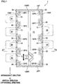
- a robot transport device 1 of an embodiment of the present invention is used in a step of processing semiconductor wafers, and includes a transportation space 10 in which a transport robot 20 is provided, as shown in FIG. 1 .
- the transportation space 10 is formed of a frame 10F which is constituted by pillar portions 10P1 to 10P10 and wall portions 10W1 to 10W4.
- a circulation passage 30 is provided to circulate gas (e.g., air, inert gas, and sterilizing gas) in the transportation space 10.
- gas e.g., air, inert gas, and sterilizing gas
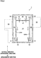
- Each circulation passage 30 extends along the vertical direction (orthogonal direction).
- wall portions 10W1 to 10W4 wall portions 10W1 and 10W2 oppose to each other, and four openings 15 are formed in the wall portion 10W1 whereas two openings 15 are formed in the wall portion 10W2.
- the openings 15 are lined up in an arrangement direction indicated in FIG. 1 .
- the pillar portions 10P1 to 10P5 are connected to the wall portion 10W1, whereas the pillar portions 10P6 to 10P10 are connected to the wall portion 10W2.
- One of the circulation passages 30 is provided between every pair of openings 15 which neighbor each other in the arrangement direction.
- a plurality of surrounding spaces e.g., a load port device and a load lock chamber
- an object a semiconductor wafer in the present embodiment
- four surrounding spaces 50 are disposed to oppose the wall portion 10W1 and two surrounding spaces 50 are disposed to oppose the wall portion 10W2.
- the transportation space 10 is able to communicate with each of the surrounding spaces 50 via each of the openings 15.
- Each opening 15 is provided with a door (not illustrated). As the door is opened or closed, the transportation space 10 and the surrounding space 50 communicate with each other via the opening 15 or the communication is blocked.
- the transport robot 20 is movable in the arrangement direction of the openings 15.
- a working area 20R of the transport robot 20 includes the substantially entire transportation space 10, each opening 15, and a part of each surrounding space 50.
- the circulation passages 30 are provided to sandwich the transportation space 10 so as to avoid the working area 20R.
- the circulation passages 30 extend to be parallel to one another along the vertical direction.
- Each circulation passage 30 communicates with the transportation space 10 via an intake port 31 on one end side (lower side) and an exhaust port 32 on the other end side (upper side).
- the intake port 31 and the exhaust port 32 are openings formed at a lower end portion and an upper end portion of each of the pillar portions 10P1 to 10P10.
- Each circulation passage 30 is structured to return the gas in the transportation space 10 sucked through the intake port 31, from the exhaust port 32 to the transportation space 10.
- the robot transport device 1 further includes a shared space 40 which allows the exhaust ports 32 of the circulation passages 30 to communicate with the transportation space 10.
- the shared space 40 is provided above the transportation space 10 (i.e., at a ceiling part of the robot transport device 1) and spreads over the entire horizontal plane (orthogonal to the orthogonal direction) relative to the transportation space 10.
- the gas exhausted from the exhaust ports 32 of the circulation passages 30 flows from the other end side (upper side) toward the one end side (lower side) in the vertical direction and returns to the transportation space 10 via the shared space 40.
- the robot transport device 1 further includes a filter 41 which is provided in a region where the gas circulated in the transportation space 10 and the circulation passages 30 passes.
- the filter 41 is arranged to remove dust from the gas.
- the filter 41 is provided between the transportation space 10 and the shared space 40 and extends along the horizontal plane.
- fans 42 are provided in the shared space 40 and in the vicinity of the intake ports 31 in the transportation space 10.
- the circulation passages 30 are provided to sandwich the transportation space 10 in the present embodiment. It is therefore possible to adjust the environments in the entire transportation space 10 to be uniform by circulating the gas in the entire transportation space 10.
- the circulation passages 30 are provided in the pillar portions 10P1 to 10P10 forming the transportation space 10. This makes it possible to downsize the entire robot transport device 1. To put it differently, according to the aspect described above, it is possible to achieve both arranging the environments in the entire transportation space 10 to be uniform by circulating the gas in the entire transportation space 10, and downsizing the robot transport device 1 on the whole.
- the pillar portions 10P1 to 10P10 are connected to the wall portions 10W1 and 10W2 which form the transportation space 10 and have the openings 15. According to this arrangement, the strength of the robot transport device 1 is improved.
- One of the circulation passages 30 is provided between every pair of openings 15 which neighbor each other in the arrangement direction. With this arrangement, the circulation passages 30 are efficiently provided in a dispersed manner, and hence the environments of the entire transportation space 10 are adjustable.
- the robot transport device 1 further includes a filter 41 which is provided in a region where the gas circulated in the transportation space 10 and the circulation passages 30 passes and is arranged to remove dust from the gas. With this arrangement, dust generated by the movement of the transport robot 20 is removed by the filter 41, and hence the transportation space 10 is maintained to be clean.
- the circulation passages 30 extend to be parallel to one another along the vertical direction (orthogonal direction), and each of the circulation passages 30 communicates with the transportation space 10 via the intake port 31 on the one end side and the exhaust port 32 on the other end side and allows the gas in the transportation space 10 sucked through the intake port 31 to return to the transportation space 10 from the exhaust port 32.
- the robot transport device 1 further includes the shared space 40 which allows the exhaust ports 32 of the circulation passages 30 to communicate with the transportation space 10, and the gas exhausted from the exhaust ports 32 of the circulation passages 30 flows from the other end side (upper side) toward the one end side (lower side) in the vertical direction so as to return to the transportation space 10 via the shared space 40. With this arrangement, dust generated by the movement of the transport robot 20 is further efficiently collected, and hence the transportation space 10 is further maintained to be clean.
- the shared space 40 spreads over the entire horizontal plane (orthogonal to the orthogonal direction) relative to the transportation space 10. This arrangement makes it possible to deliver the gas to the entirety of the transportation space 10.
- the robot transport device of the present invention is not necessarily used in the step of processing semiconductor wafers.
- the device may be used in a step of processing liquid crystal display panels, a step of culturing or testing cells, or any other steps.
- the objects to be transported may be variously changed in accordance with the step in which the robot transport device is used.
- the robot transport device is used for the step of processing liquid crystal display panels, the liquid crystal display panels are the objects.
- Clean air, gas, or the like may be supplied to the transportation space via the circulation passages, and gas including the supplied gas may be circulated in the entire transportation space.
- the circulation passages do not necessarily extend in the vertical direction, and may extend in the horizontal direction, for example.
- the circulation passages may not be parallel to one another, and may intersect with one another. (For example, a circulation passage extending in the vertical direction and a circulation passage extending in the horizontal direction may be provided.)
- Each circulation passage may not be linear in shape but curved in shape.
- the positions and the number of the fans are not particularly limited, on condition that gas flows circulating in the transportation space and the circulation passages are generated.
- a temperature humidity controller may be provided.
- the temperature humidity controller include a dryer for decreasing humidity, a cooler for decreasing temperature, and an ionizer for removing electricity from semiconductor wafers. This arrangement makes it possible to keep the temperature of the entire transportation space to be uniform.
- the surrounding spaces may be provided at any given positions of the transportation space.
- the surrounding spaces may be provided to entirely surround the circumference of the transportation space.
- surrounding spaces opposing the wall portions 10W3 and 10W4 may be further provided.
- the surrounding spaces may be provided only on one side of the transportation space.
- the surrounding spaces may be provided only at the wall portion 10W1 or only at the wall portion 10W2.
- the surrounding spaces may be identical with one another or different from one another.
- Each opening may not be provided with a door.
- the arrangement direction of the openings may not be the horizontal direction but be the vertical direction, for example.
- the moving direction of the transport robot may not be the horizontal direction but be the vertical direction, for example.
Applications Claiming Priority (2)
| Application Number | Priority Date | Filing Date | Title |
|---|---|---|---|
| JP2015220290A JP6555091B2 (ja) | 2015-11-10 | 2015-11-10 | ロボット搬送装置 |
| PCT/JP2016/082103 WO2017082086A1 (ja) | 2015-11-10 | 2016-10-28 | ロボット搬送装置 |
Publications (3)
| Publication Number | Publication Date |
|---|---|
| EP3376529A1 EP3376529A1 (en) | 2018-09-19 |
| EP3376529A4 EP3376529A4 (en) | 2019-07-03 |
| EP3376529B1 true EP3376529B1 (en) | 2020-07-29 |
Family
ID=58695271
Family Applications (1)
| Application Number | Title | Priority Date | Filing Date |
|---|---|---|---|
| EP16864049.8A Active EP3376529B1 (en) | 2015-11-10 | 2016-10-28 | Robot transport device |
Country Status (6)
| Country | Link |
|---|---|
| US (1) | US10636680B2 (ko) |
| EP (1) | EP3376529B1 (ko) |
| JP (1) | JP6555091B2 (ko) |
| KR (1) | KR102602973B1 (ko) |
| CN (1) | CN108431942B (ko) |
| WO (1) | WO2017082086A1 (ko) |
Families Citing this family (3)
| Publication number | Priority date | Publication date | Assignee | Title |
|---|---|---|---|---|
| JP7037049B2 (ja) * | 2018-03-15 | 2022-03-16 | シンフォニアテクノロジー株式会社 | Efem |
| JP7140960B2 (ja) * | 2018-03-15 | 2022-09-22 | シンフォニアテクノロジー株式会社 | Efem |
| US11373891B2 (en) * | 2018-10-26 | 2022-06-28 | Applied Materials, Inc. | Front-ducted equipment front end modules, side storage pods, and methods of operating the same |
Family Cites Families (17)
| Publication number | Priority date | Publication date | Assignee | Title |
|---|---|---|---|---|
| EP0322205A3 (en) | 1987-12-23 | 1990-09-12 | Texas Instruments Incorporated | Automated photolithographic work cell |
| JPH0462345A (ja) * | 1990-06-29 | 1992-02-27 | Hitachi Ltd | クリーンルーム内の吸気ダクト方式 |
| JP3882340B2 (ja) * | 1998-06-01 | 2007-02-14 | 村田機械株式会社 | クリーンルーム用自動倉庫 |
| JP3441681B2 (ja) * | 1998-08-14 | 2003-09-02 | 東京エレクトロン株式会社 | 処理装置 |
| KR100515740B1 (ko) * | 1998-08-14 | 2005-09-20 | 동경 엘렉트론 주식회사 | 기판처리장치 |
| JP3556134B2 (ja) * | 1999-10-01 | 2004-08-18 | 三進金属工業株式会社 | 空気清浄機能付棚 |
| JP2004179519A (ja) * | 2002-11-28 | 2004-06-24 | Tokyo Ohka Kogyo Co Ltd | 基板処理装置 |
| KR100486690B1 (ko) * | 2002-11-29 | 2005-05-03 | 삼성전자주식회사 | 기판 이송 모듈의 오염을 제어할 수 있는 기판 처리 장치및 방법 |
| KR100505061B1 (ko) * | 2003-02-12 | 2005-08-01 | 삼성전자주식회사 | 기판 이송 모듈 |
| JP2005311260A (ja) * | 2004-04-26 | 2005-11-04 | Hitachi Plant Eng & Constr Co Ltd | 液晶基板の保管倉庫室 |
| JP2007003069A (ja) * | 2005-06-22 | 2007-01-11 | Hitachi Plant Technologies Ltd | ミニエンバイロメント装置及びミニエンバイロメント装置の循環流制御方法 |
| JP2010077508A (ja) * | 2008-09-26 | 2010-04-08 | Tokyo Electron Ltd | 成膜装置及び基板処理装置 |
| JP5181100B2 (ja) * | 2009-04-09 | 2013-04-10 | 東京エレクトロン株式会社 | 基板処理装置、基板処理方法及び記憶媒体 |
| JP4936567B2 (ja) * | 2009-09-18 | 2012-05-23 | 東京エレクトロン株式会社 | 熱処理装置 |
| TWI635552B (zh) | 2013-12-13 | 2018-09-11 | 昕芙旎雅股份有限公司 | 設備前端模組(efem) |
| JP6349750B2 (ja) * | 2014-01-31 | 2018-07-04 | シンフォニアテクノロジー株式会社 | Efem |
| JP2015115517A (ja) * | 2013-12-13 | 2015-06-22 | シンフォニアテクノロジー株式会社 | 基板搬送装置及びefem |
-
2015
- 2015-11-10 JP JP2015220290A patent/JP6555091B2/ja active Active
-
2016
- 2016-10-28 EP EP16864049.8A patent/EP3376529B1/en active Active
- 2016-10-28 KR KR1020187013147A patent/KR102602973B1/ko active IP Right Grant
- 2016-10-28 WO PCT/JP2016/082103 patent/WO2017082086A1/ja active Application Filing
- 2016-10-28 CN CN201680065918.1A patent/CN108431942B/zh active Active
- 2016-10-28 US US15/774,882 patent/US10636680B2/en active Active
Non-Patent Citations (1)
| Title |
|---|
| None * |
Also Published As
| Publication number | Publication date |
|---|---|
| CN108431942B (zh) | 2023-03-24 |
| US20180323086A1 (en) | 2018-11-08 |
| CN108431942A (zh) | 2018-08-21 |
| WO2017082086A1 (ja) | 2017-05-18 |
| KR102602973B1 (ko) | 2023-11-17 |
| EP3376529A4 (en) | 2019-07-03 |
| KR20180080233A (ko) | 2018-07-11 |
| JP2017092233A (ja) | 2017-05-25 |
| EP3376529A1 (en) | 2018-09-19 |
| JP6555091B2 (ja) | 2019-08-07 |
| US10636680B2 (en) | 2020-04-28 |
Similar Documents
| Publication | Publication Date | Title |
|---|---|---|
| EP3376529B1 (en) | Robot transport device | |
| KR102357510B1 (ko) | 격납 유닛, 반송 장치, 및 기판 처리 시스템 | |
| US20160207082A1 (en) | Gas purge unit and gas purge apparatus | |
| US9159600B2 (en) | Wafer transport apparatus | |
| JP7125589B2 (ja) | Efemシステム及びefemシステムにおけるガス供給方法 | |
| JP7001910B2 (ja) | ロボット搬送装置 | |
| KR20200129109A (ko) | 이에프이엠 | |
| US20160296984A1 (en) | Purge device and method of diffusing gas including purge gas | |
| KR102411760B1 (ko) | 웨이퍼 검사 장치 | |
| JP6309783B2 (ja) | 空調システム | |
| JP6005030B2 (ja) | 蓄電装置 | |
| KR20170084113A (ko) | 냉기 통로를 공기 조화시키기 위한 방법 및 장치 | |
| US20180130681A1 (en) | Processing system | |
| US20160293454A1 (en) | Substrate processing device | |
| EP2058852A2 (en) | Vertical carousel and vertical transportation method using the vertical carousel | |
| JP2011247492A (ja) | クリーンルーム | |
| US10497588B2 (en) | EFEM, equipment front end module | |
| KR102652346B1 (ko) | 이에프이엠 | |
| JP2011185544A (ja) | 発熱機器用のラック空調装置 | |
| KR102011146B1 (ko) | 에피택셜 웨이퍼 제조장치 | |
| WO2018179498A1 (ja) | クリーンルーム設備 | |
| JP2010048467A (ja) | 板状体冷却装置及び熱処理システム | |
| JP2019039613A (ja) | クリーンルーム設備 |
Legal Events
| Date | Code | Title | Description |
|---|---|---|---|
| STAA | Information on the status of an ep patent application or granted ep patent |
Free format text: STATUS: THE INTERNATIONAL PUBLICATION HAS BEEN MADE |
|
| PUAI | Public reference made under article 153(3) epc to a published international application that has entered the european phase |
Free format text: ORIGINAL CODE: 0009012 |
|
| STAA | Information on the status of an ep patent application or granted ep patent |
Free format text: STATUS: REQUEST FOR EXAMINATION WAS MADE |
|
| 17P | Request for examination filed |
Effective date: 20180608 |
|
| AK | Designated contracting states |
Kind code of ref document: A1 Designated state(s): AL AT BE BG CH CY CZ DE DK EE ES FI FR GB GR HR HU IE IS IT LI LT LU LV MC MK MT NL NO PL PT RO RS SE SI SK SM TR |
|
| AX | Request for extension of the european patent |
Extension state: BA ME |
|
| DAV | Request for validation of the european patent (deleted) | ||
| DAX | Request for extension of the european patent (deleted) | ||
| A4 | Supplementary search report drawn up and despatched |
Effective date: 20190531 |
|
| RIC1 | Information provided on ipc code assigned before grant |
Ipc: B25J 5/00 20060101ALI20190524BHEP Ipc: B25J 15/00 20060101ALI20190524BHEP Ipc: H01L 21/677 20060101AFI20190524BHEP Ipc: H01L 21/67 20060101ALI20190524BHEP |
|
| GRAP | Despatch of communication of intention to grant a patent |
Free format text: ORIGINAL CODE: EPIDOSNIGR1 |
|
| STAA | Information on the status of an ep patent application or granted ep patent |
Free format text: STATUS: GRANT OF PATENT IS INTENDED |
|
| INTG | Intention to grant announced |
Effective date: 20200220 |
|
| GRAS | Grant fee paid |
Free format text: ORIGINAL CODE: EPIDOSNIGR3 |
|
| GRAA | (expected) grant |
Free format text: ORIGINAL CODE: 0009210 |
|
| STAA | Information on the status of an ep patent application or granted ep patent |
Free format text: STATUS: THE PATENT HAS BEEN GRANTED |
|
| AK | Designated contracting states |
Kind code of ref document: B1 Designated state(s): AL AT BE BG CH CY CZ DE DK EE ES FI FR GB GR HR HU IE IS IT LI LT LU LV MC MK MT NL NO PL PT RO RS SE SI SK SM TR |
|
| REG | Reference to a national code |
Ref country code: CH Ref legal event code: EP |
|
| REG | Reference to a national code |
Ref country code: AT Ref legal event code: REF Ref document number: 1296792 Country of ref document: AT Kind code of ref document: T Effective date: 20200815 |
|
| REG | Reference to a national code |
Ref country code: IE Ref legal event code: FG4D |
|
| REG | Reference to a national code |
Ref country code: DE Ref legal event code: R096 Ref document number: 602016041055 Country of ref document: DE |
|
| REG | Reference to a national code |
Ref country code: LT Ref legal event code: MG4D |
|
| REG | Reference to a national code |
Ref country code: NL Ref legal event code: MP Effective date: 20200729 |
|
| REG | Reference to a national code |
Ref country code: AT Ref legal event code: MK05 Ref document number: 1296792 Country of ref document: AT Kind code of ref document: T Effective date: 20200729 |
|
| PG25 | Lapsed in a contracting state [announced via postgrant information from national office to epo] |
Ref country code: AT Free format text: LAPSE BECAUSE OF FAILURE TO SUBMIT A TRANSLATION OF THE DESCRIPTION OR TO PAY THE FEE WITHIN THE PRESCRIBED TIME-LIMIT Effective date: 20200729 Ref country code: LT Free format text: LAPSE BECAUSE OF FAILURE TO SUBMIT A TRANSLATION OF THE DESCRIPTION OR TO PAY THE FEE WITHIN THE PRESCRIBED TIME-LIMIT Effective date: 20200729 Ref country code: HR Free format text: LAPSE BECAUSE OF FAILURE TO SUBMIT A TRANSLATION OF THE DESCRIPTION OR TO PAY THE FEE WITHIN THE PRESCRIBED TIME-LIMIT Effective date: 20200729 Ref country code: NO Free format text: LAPSE BECAUSE OF FAILURE TO SUBMIT A TRANSLATION OF THE DESCRIPTION OR TO PAY THE FEE WITHIN THE PRESCRIBED TIME-LIMIT Effective date: 20201029 Ref country code: FI Free format text: LAPSE BECAUSE OF FAILURE TO SUBMIT A TRANSLATION OF THE DESCRIPTION OR TO PAY THE FEE WITHIN THE PRESCRIBED TIME-LIMIT Effective date: 20200729 Ref country code: PT Free format text: LAPSE BECAUSE OF FAILURE TO SUBMIT A TRANSLATION OF THE DESCRIPTION OR TO PAY THE FEE WITHIN THE PRESCRIBED TIME-LIMIT Effective date: 20201130 Ref country code: SE Free format text: LAPSE BECAUSE OF FAILURE TO SUBMIT A TRANSLATION OF THE DESCRIPTION OR TO PAY THE FEE WITHIN THE PRESCRIBED TIME-LIMIT Effective date: 20200729 Ref country code: GR Free format text: LAPSE BECAUSE OF FAILURE TO SUBMIT A TRANSLATION OF THE DESCRIPTION OR TO PAY THE FEE WITHIN THE PRESCRIBED TIME-LIMIT Effective date: 20201030 Ref country code: ES Free format text: LAPSE BECAUSE OF FAILURE TO SUBMIT A TRANSLATION OF THE DESCRIPTION OR TO PAY THE FEE WITHIN THE PRESCRIBED TIME-LIMIT Effective date: 20200729 Ref country code: BG Free format text: LAPSE BECAUSE OF FAILURE TO SUBMIT A TRANSLATION OF THE DESCRIPTION OR TO PAY THE FEE WITHIN THE PRESCRIBED TIME-LIMIT Effective date: 20201029 |
|
| PG25 | Lapsed in a contracting state [announced via postgrant information from national office to epo] |
Ref country code: LV Free format text: LAPSE BECAUSE OF FAILURE TO SUBMIT A TRANSLATION OF THE DESCRIPTION OR TO PAY THE FEE WITHIN THE PRESCRIBED TIME-LIMIT Effective date: 20200729 Ref country code: PL Free format text: LAPSE BECAUSE OF FAILURE TO SUBMIT A TRANSLATION OF THE DESCRIPTION OR TO PAY THE FEE WITHIN THE PRESCRIBED TIME-LIMIT Effective date: 20200729 Ref country code: RS Free format text: LAPSE BECAUSE OF FAILURE TO SUBMIT A TRANSLATION OF THE DESCRIPTION OR TO PAY THE FEE WITHIN THE PRESCRIBED TIME-LIMIT Effective date: 20200729 Ref country code: IS Free format text: LAPSE BECAUSE OF FAILURE TO SUBMIT A TRANSLATION OF THE DESCRIPTION OR TO PAY THE FEE WITHIN THE PRESCRIBED TIME-LIMIT Effective date: 20201129 |
|
| PG25 | Lapsed in a contracting state [announced via postgrant information from national office to epo] |
Ref country code: NL Free format text: LAPSE BECAUSE OF FAILURE TO SUBMIT A TRANSLATION OF THE DESCRIPTION OR TO PAY THE FEE WITHIN THE PRESCRIBED TIME-LIMIT Effective date: 20200729 |
|
| PG25 | Lapsed in a contracting state [announced via postgrant information from national office to epo] |
Ref country code: CZ Free format text: LAPSE BECAUSE OF FAILURE TO SUBMIT A TRANSLATION OF THE DESCRIPTION OR TO PAY THE FEE WITHIN THE PRESCRIBED TIME-LIMIT Effective date: 20200729 Ref country code: DK Free format text: LAPSE BECAUSE OF FAILURE TO SUBMIT A TRANSLATION OF THE DESCRIPTION OR TO PAY THE FEE WITHIN THE PRESCRIBED TIME-LIMIT Effective date: 20200729 Ref country code: RO Free format text: LAPSE BECAUSE OF FAILURE TO SUBMIT A TRANSLATION OF THE DESCRIPTION OR TO PAY THE FEE WITHIN THE PRESCRIBED TIME-LIMIT Effective date: 20200729 Ref country code: SM Free format text: LAPSE BECAUSE OF FAILURE TO SUBMIT A TRANSLATION OF THE DESCRIPTION OR TO PAY THE FEE WITHIN THE PRESCRIBED TIME-LIMIT Effective date: 20200729 Ref country code: EE Free format text: LAPSE BECAUSE OF FAILURE TO SUBMIT A TRANSLATION OF THE DESCRIPTION OR TO PAY THE FEE WITHIN THE PRESCRIBED TIME-LIMIT Effective date: 20200729 Ref country code: IT Free format text: LAPSE BECAUSE OF FAILURE TO SUBMIT A TRANSLATION OF THE DESCRIPTION OR TO PAY THE FEE WITHIN THE PRESCRIBED TIME-LIMIT Effective date: 20200729 |
|
| REG | Reference to a national code |
Ref country code: DE Ref legal event code: R097 Ref document number: 602016041055 Country of ref document: DE |
|
| PG25 | Lapsed in a contracting state [announced via postgrant information from national office to epo] |
Ref country code: AL Free format text: LAPSE BECAUSE OF FAILURE TO SUBMIT A TRANSLATION OF THE DESCRIPTION OR TO PAY THE FEE WITHIN THE PRESCRIBED TIME-LIMIT Effective date: 20200729 |
|
| REG | Reference to a national code |
Ref country code: CH Ref legal event code: PL |
|
| PLBE | No opposition filed within time limit |
Free format text: ORIGINAL CODE: 0009261 |
|
| STAA | Information on the status of an ep patent application or granted ep patent |
Free format text: STATUS: NO OPPOSITION FILED WITHIN TIME LIMIT |
|
| GBPC | Gb: european patent ceased through non-payment of renewal fee |
Effective date: 20201029 |
|
| PG25 | Lapsed in a contracting state [announced via postgrant information from national office to epo] |
Ref country code: LU Free format text: LAPSE BECAUSE OF NON-PAYMENT OF DUE FEES Effective date: 20201028 Ref country code: MC Free format text: LAPSE BECAUSE OF FAILURE TO SUBMIT A TRANSLATION OF THE DESCRIPTION OR TO PAY THE FEE WITHIN THE PRESCRIBED TIME-LIMIT Effective date: 20200729 Ref country code: SK Free format text: LAPSE BECAUSE OF FAILURE TO SUBMIT A TRANSLATION OF THE DESCRIPTION OR TO PAY THE FEE WITHIN THE PRESCRIBED TIME-LIMIT Effective date: 20200729 |
|
| 26N | No opposition filed |
Effective date: 20210430 |
|
| REG | Reference to a national code |
Ref country code: BE Ref legal event code: MM Effective date: 20201031 |
|
| PG25 | Lapsed in a contracting state [announced via postgrant information from national office to epo] |
Ref country code: CH Free format text: LAPSE BECAUSE OF NON-PAYMENT OF DUE FEES Effective date: 20201031 Ref country code: BE Free format text: LAPSE BECAUSE OF NON-PAYMENT OF DUE FEES Effective date: 20201031 Ref country code: SI Free format text: LAPSE BECAUSE OF FAILURE TO SUBMIT A TRANSLATION OF THE DESCRIPTION OR TO PAY THE FEE WITHIN THE PRESCRIBED TIME-LIMIT Effective date: 20200729 Ref country code: GB Free format text: LAPSE BECAUSE OF NON-PAYMENT OF DUE FEES Effective date: 20201029 Ref country code: LI Free format text: LAPSE BECAUSE OF NON-PAYMENT OF DUE FEES Effective date: 20201031 |
|
| PG25 | Lapsed in a contracting state [announced via postgrant information from national office to epo] |
Ref country code: IE Free format text: LAPSE BECAUSE OF NON-PAYMENT OF DUE FEES Effective date: 20201028 |
|
| PG25 | Lapsed in a contracting state [announced via postgrant information from national office to epo] |
Ref country code: TR Free format text: LAPSE BECAUSE OF FAILURE TO SUBMIT A TRANSLATION OF THE DESCRIPTION OR TO PAY THE FEE WITHIN THE PRESCRIBED TIME-LIMIT Effective date: 20200729 Ref country code: MT Free format text: LAPSE BECAUSE OF FAILURE TO SUBMIT A TRANSLATION OF THE DESCRIPTION OR TO PAY THE FEE WITHIN THE PRESCRIBED TIME-LIMIT Effective date: 20200729 Ref country code: CY Free format text: LAPSE BECAUSE OF FAILURE TO SUBMIT A TRANSLATION OF THE DESCRIPTION OR TO PAY THE FEE WITHIN THE PRESCRIBED TIME-LIMIT Effective date: 20200729 |
|
| PG25 | Lapsed in a contracting state [announced via postgrant information from national office to epo] |
Ref country code: MK Free format text: LAPSE BECAUSE OF FAILURE TO SUBMIT A TRANSLATION OF THE DESCRIPTION OR TO PAY THE FEE WITHIN THE PRESCRIBED TIME-LIMIT Effective date: 20200729 |
|
| REG | Reference to a national code |
Ref country code: DE Ref legal event code: R082 Ref document number: 602016041055 Country of ref document: DE Representative=s name: CBDL PATENTANWAELTE GBR, DE |
|
| P01 | Opt-out of the competence of the unified patent court (upc) registered |
Effective date: 20230512 |
|
| PGFP | Annual fee paid to national office [announced via postgrant information from national office to epo] |
Ref country code: FR Payment date: 20231026 Year of fee payment: 8 Ref country code: DE Payment date: 20231020 Year of fee payment: 8 |