EP3376486A1 - Überwachungsvorrichtung und überwachungsverfahren - Google Patents
Überwachungsvorrichtung und überwachungsverfahren Download PDFInfo
- Publication number
- EP3376486A1 EP3376486A1 EP16864331.0A EP16864331A EP3376486A1 EP 3376486 A1 EP3376486 A1 EP 3376486A1 EP 16864331 A EP16864331 A EP 16864331A EP 3376486 A1 EP3376486 A1 EP 3376486A1
- Authority
- EP
- European Patent Office
- Prior art keywords
- detection area
- vehicle
- case
- traveling
- monitoring device
- Prior art date
- Legal status (The legal status is an assumption and is not a legal conclusion. Google has not performed a legal analysis and makes no representation as to the accuracy of the status listed.)
- Granted
Links
- 238000012806 monitoring device Methods 0.000 title claims abstract description 28
- 238000000034 method Methods 0.000 title claims description 57
- 238000012544 monitoring process Methods 0.000 title claims description 6
- 238000001514 detection method Methods 0.000 claims abstract description 136
- 238000012545 processing Methods 0.000 description 50
- 238000010586 diagram Methods 0.000 description 8
- 238000005516 engineering process Methods 0.000 description 5
- 230000005540 biological transmission Effects 0.000 description 4
- 230000007423 decrease Effects 0.000 description 3
- 239000002184 metal Substances 0.000 description 2
- 229910052751 metal Inorganic materials 0.000 description 2
- 230000004397 blinking Effects 0.000 description 1
- 238000004891 communication Methods 0.000 description 1
- 230000006866 deterioration Effects 0.000 description 1
- 238000006073 displacement reaction Methods 0.000 description 1
- 230000000694 effects Effects 0.000 description 1
- 238000002474 experimental method Methods 0.000 description 1
- 230000007935 neutral effect Effects 0.000 description 1
Images


Classifications
-
- G—PHYSICS
- G08—SIGNALLING
- G08G—TRAFFIC CONTROL SYSTEMS
- G08G1/00—Traffic control systems for road vehicles
- G08G1/16—Anti-collision systems
- G08G1/167—Driving aids for lane monitoring, lane changing, e.g. blind spot detection
-
- G—PHYSICS
- G01—MEASURING; TESTING
- G01S—RADIO DIRECTION-FINDING; RADIO NAVIGATION; DETERMINING DISTANCE OR VELOCITY BY USE OF RADIO WAVES; LOCATING OR PRESENCE-DETECTING BY USE OF THE REFLECTION OR RERADIATION OF RADIO WAVES; ANALOGOUS ARRANGEMENTS USING OTHER WAVES
- G01S13/00—Systems using the reflection or reradiation of radio waves, e.g. radar systems; Analogous systems using reflection or reradiation of waves whose nature or wavelength is irrelevant or unspecified
- G01S13/02—Systems using reflection of radio waves, e.g. primary radar systems; Analogous systems
- G01S13/50—Systems of measurement based on relative movement of target
- G01S13/52—Discriminating between fixed and moving objects or between objects moving at different speeds
- G01S13/56—Discriminating between fixed and moving objects or between objects moving at different speeds for presence detection
-
- B—PERFORMING OPERATIONS; TRANSPORTING
- B60—VEHICLES IN GENERAL
- B60R—VEHICLES, VEHICLE FITTINGS, OR VEHICLE PARTS, NOT OTHERWISE PROVIDED FOR
- B60R21/00—Arrangements or fittings on vehicles for protecting or preventing injuries to occupants or pedestrians in case of accidents or other traffic risks
- B60R21/34—Protecting non-occupants of a vehicle, e.g. pedestrians
-
- B—PERFORMING OPERATIONS; TRANSPORTING
- B60—VEHICLES IN GENERAL
- B60W—CONJOINT CONTROL OF VEHICLE SUB-UNITS OF DIFFERENT TYPE OR DIFFERENT FUNCTION; CONTROL SYSTEMS SPECIALLY ADAPTED FOR HYBRID VEHICLES; ROAD VEHICLE DRIVE CONTROL SYSTEMS FOR PURPOSES NOT RELATED TO THE CONTROL OF A PARTICULAR SUB-UNIT
- B60W30/00—Purposes of road vehicle drive control systems not related to the control of a particular sub-unit, e.g. of systems using conjoint control of vehicle sub-units
- B60W30/08—Active safety systems predicting or avoiding probable or impending collision or attempting to minimise its consequences
- B60W30/095—Predicting travel path or likelihood of collision
- B60W30/0956—Predicting travel path or likelihood of collision the prediction being responsive to traffic or environmental parameters
-
- B—PERFORMING OPERATIONS; TRANSPORTING
- B60—VEHICLES IN GENERAL
- B60W—CONJOINT CONTROL OF VEHICLE SUB-UNITS OF DIFFERENT TYPE OR DIFFERENT FUNCTION; CONTROL SYSTEMS SPECIALLY ADAPTED FOR HYBRID VEHICLES; ROAD VEHICLE DRIVE CONTROL SYSTEMS FOR PURPOSES NOT RELATED TO THE CONTROL OF A PARTICULAR SUB-UNIT
- B60W50/00—Details of control systems for road vehicle drive control not related to the control of a particular sub-unit, e.g. process diagnostic or vehicle driver interfaces
- B60W50/08—Interaction between the driver and the control system
- B60W50/14—Means for informing the driver, warning the driver or prompting a driver intervention
-
- G—PHYSICS
- G01—MEASURING; TESTING
- G01S—RADIO DIRECTION-FINDING; RADIO NAVIGATION; DETERMINING DISTANCE OR VELOCITY BY USE OF RADIO WAVES; LOCATING OR PRESENCE-DETECTING BY USE OF THE REFLECTION OR RERADIATION OF RADIO WAVES; ANALOGOUS ARRANGEMENTS USING OTHER WAVES
- G01S13/00—Systems using the reflection or reradiation of radio waves, e.g. radar systems; Analogous systems using reflection or reradiation of waves whose nature or wavelength is irrelevant or unspecified
- G01S13/02—Systems using reflection of radio waves, e.g. primary radar systems; Analogous systems
- G01S13/04—Systems determining presence of a target
-
- G—PHYSICS
- G01—MEASURING; TESTING
- G01S—RADIO DIRECTION-FINDING; RADIO NAVIGATION; DETERMINING DISTANCE OR VELOCITY BY USE OF RADIO WAVES; LOCATING OR PRESENCE-DETECTING BY USE OF THE REFLECTION OR RERADIATION OF RADIO WAVES; ANALOGOUS ARRANGEMENTS USING OTHER WAVES
- G01S13/00—Systems using the reflection or reradiation of radio waves, e.g. radar systems; Analogous systems using reflection or reradiation of waves whose nature or wavelength is irrelevant or unspecified
- G01S13/88—Radar or analogous systems specially adapted for specific applications
- G01S13/93—Radar or analogous systems specially adapted for specific applications for anti-collision purposes
- G01S13/931—Radar or analogous systems specially adapted for specific applications for anti-collision purposes of land vehicles
-
- G—PHYSICS
- G08—SIGNALLING
- G08B—SIGNALLING OR CALLING SYSTEMS; ORDER TELEGRAPHS; ALARM SYSTEMS
- G08B21/00—Alarms responsive to a single specified undesired or abnormal condition and not otherwise provided for
-
- G—PHYSICS
- G08—SIGNALLING
- G08G—TRAFFIC CONTROL SYSTEMS
- G08G1/00—Traffic control systems for road vehicles
- G08G1/16—Anti-collision systems
-
- G—PHYSICS
- G08—SIGNALLING
- G08G—TRAFFIC CONTROL SYSTEMS
- G08G1/00—Traffic control systems for road vehicles
- G08G1/16—Anti-collision systems
- G08G1/166—Anti-collision systems for active traffic, e.g. moving vehicles, pedestrians, bikes
-
- B—PERFORMING OPERATIONS; TRANSPORTING
- B60—VEHICLES IN GENERAL
- B60W—CONJOINT CONTROL OF VEHICLE SUB-UNITS OF DIFFERENT TYPE OR DIFFERENT FUNCTION; CONTROL SYSTEMS SPECIALLY ADAPTED FOR HYBRID VEHICLES; ROAD VEHICLE DRIVE CONTROL SYSTEMS FOR PURPOSES NOT RELATED TO THE CONTROL OF A PARTICULAR SUB-UNIT
- B60W50/00—Details of control systems for road vehicle drive control not related to the control of a particular sub-unit, e.g. process diagnostic or vehicle driver interfaces
- B60W50/08—Interaction between the driver and the control system
- B60W50/14—Means for informing the driver, warning the driver or prompting a driver intervention
- B60W2050/143—Alarm means
-
- B—PERFORMING OPERATIONS; TRANSPORTING
- B60—VEHICLES IN GENERAL
- B60W—CONJOINT CONTROL OF VEHICLE SUB-UNITS OF DIFFERENT TYPE OR DIFFERENT FUNCTION; CONTROL SYSTEMS SPECIALLY ADAPTED FOR HYBRID VEHICLES; ROAD VEHICLE DRIVE CONTROL SYSTEMS FOR PURPOSES NOT RELATED TO THE CONTROL OF A PARTICULAR SUB-UNIT
- B60W2554/00—Input parameters relating to objects
- B60W2554/40—Dynamic objects, e.g. animals, windblown objects
- B60W2554/402—Type
-
- G—PHYSICS
- G01—MEASURING; TESTING
- G01S—RADIO DIRECTION-FINDING; RADIO NAVIGATION; DETERMINING DISTANCE OR VELOCITY BY USE OF RADIO WAVES; LOCATING OR PRESENCE-DETECTING BY USE OF THE REFLECTION OR RERADIATION OF RADIO WAVES; ANALOGOUS ARRANGEMENTS USING OTHER WAVES
- G01S13/00—Systems using the reflection or reradiation of radio waves, e.g. radar systems; Analogous systems using reflection or reradiation of waves whose nature or wavelength is irrelevant or unspecified
- G01S13/88—Radar or analogous systems specially adapted for specific applications
- G01S13/93—Radar or analogous systems specially adapted for specific applications for anti-collision purposes
- G01S13/931—Radar or analogous systems specially adapted for specific applications for anti-collision purposes of land vehicles
- G01S2013/9315—Monitoring blind spots
Definitions
- the present invention relates to a monitoring device and a monitoring method.
- Patent document 1 discloses a technology regarding a warning device for preventing a minor collision with a following vehicle when a host vehicle changes a lane.
- the technology is referred to as Blind Spot Detection (BSD) or the like.
- BBD Blind Spot Detection
- the technology is capable of detecting a blind spot of a driver.
- Patent document 2 discloses a vehicle rear side warning device configured not to issue a warning against a roadside stationary object such as a guardrail and a wall and to issue a warning against a vehicle approaching from behind or a vehicle staying in a blind spot area of the host vehicle.
- Patent document 3 discloses a technology to detect a host vehicle position with respect to a lane width, thus preventing deterioration in an accuracy of detecting another vehicle due to a shift of a rear side warning area resulting from a displacement of the host vehicle in a lateral direction.
- a warning may continue to be issued in a case of low-speed driving due to a traffic jam or the like because more vehicles than usual are approaching the host vehicle from rearward side. Thus, measures have been taken such that a warning is not issued under such conditions.
- a warning device during the low-speed driving may cause following problems.
- the warning cannot be issued even in a case that an object such as a two-wheel vehicle passing through either side of the host vehicle is present, or when the driver of the host vehicle attempts to park the host vehicle at a shoulder of a road, a warning cannot be issued even in a case that an object such as a two-wheel vehicle passing between the shoulder of the road and the host vehicle is present.
- An object of the present invention is to provide a monitoring device and a monitoring method capable of reliably detecting an object entering an area on either side of a host vehicle during low-speed driving or the like.
- This configuration enables the monitoring device to reliably detect an object entering an area on either side of the host vehicle.
- the monitoring device further includes an alarm configured to issue a warning in a case that the controller selects the second detection area and the radar detects an object present in the second detection area.
- This configuration enables the monitoring device to attract attention of a driver in a case that an object entering an area on either side of the host vehicle is detected.
- the controller is configured to select the second detection area in a case that the detector detects the vehicle traveling forward at a speed less than or equal to a predetermined speed.
- This configuration enables the monitoring device to reliably detect an object entering an area on either side of the host vehicle with a simple configuration.
- the alarm is configured to issue a warning in a case that the object intersects a collision determination line set at either side of a rear of the vehicle.
- This configuration enables the monitoring device to reliably detect whether an object entering an area on either side of the host vehicle collides with the host vehicle.
- the alarm is configured to issue a warning in a case that an operation for changing a traveling direction is performed in a state in which an object is detected in the second detection area.
- the alarm is configured to issue a warning in a case that an operation for opening a window or a door of the vehicle is performed in a state in which an object is detected in the second detection area.
- the controller in a case that the controller switches a detection area from the first detection area to the second detection area, or the controller switches a detection area from the second detection area to the first detection area, the controller is configured to set both the first detection area and the second detection area as a detection target for a predetermined period of time.
- the controller is configured to select the first detection area in a case that the traveling direction included in the traveling state is left or right.
- This configuration allows a broad area to be set as a detection area, avoiding not only a side collision between an object and the host vehicle changing direction but also a collision between the object and the host vehicle.
- an end of the second detection area closer to the vehicle is set to a position nearer to the vehicle than a position of an end of the first detection area closer to the vehicle.
- This configuration enables the monitoring device to reliably detect the object approaching the host vehicle and entering an area on either side of the host vehicle.
- the method includes the steps of detecting a traveling state of the vehicle, and, controlling the radar, wherein the radar is configured to perform detection in a first detection area and a second detection area, the second detection area having a width in a vehicle width direction narrower than a width of the first detection area, and the controlling the radar includes switching a detection area between the first detection area for detecting a traveling object to either side behind the vehicle and, in accordance with a traveling state not including a traveling direction in a case that the traveling direction included in the traveling state is straight forward.
- This method allows the object entering an area on either side of the host vehicle to be reliably detected.
- a monitoring device and a monitoring method can be provided that enable reliable detection of an object entering an area on either side of a host vehicle during low-speed driving or the like.
- FIG. 1 is a diagram illustrating an example of a configuration of a monitoring device according to an embodiment of the present invention.
- a monitoring device 10 includes the following primary components: an other vehicle detection unit 11, a host vehicle state detection unit 12, a calculation processing unit 13, a steering detection unit 14, a direction instruction detection unit 15, and a warning unit 16.
- the other vehicle detection unit 11 includes a radar device, for example.
- the radar device is configured to repeatedly emit pulse-like electric waves and detect a position, velocity, and the like of the other vehicle using a reflected wave thereof.
- the other vehicle detection unit 11 is also configured to detect not only a two-wheel vehicle such as a motorcycle and a bicycle, but also a four-wheel vehicle (including a three-wheel vehicle and a vehicle including five wheels or greater), a pedestrian, and the like, as a target.
- the host vehicle state detection unit 12 includes a vehicle speed sensor, a yaw axis sensor, a sensor configured to detect a state of a transmission, and a sensor configured to detect an open-close state of a door or a window, for example.
- the host vehicle state detection unit 12 is configured to detect a traveling state of the host vehicle and notify the calculation processing unit 13 of the detected state.
- the calculation processing unit 13 includes a Central Processing Unit (CPU), a Digital Signal Processor (DSP), and a Field Programmable Gate Array (FPGA), for example.
- the calculation processing unit 13 is configured to detect a four-wheel vehicle or a two-wheel vehicle traveling behind the host vehicle in accordance with information supplied from the other vehicle detection unit 11, the host vehicle state detection unit 12, the steering detection unit 14, and the direction instruction detection unit 15, and determine whether the two-wheel vehicle or the four-wheel vehicle will possibly collide with the host vehicle.
- the calculation processing unit 13 causes the warning unit 16 to issue a warning in a case that the calculation processing unit 13 determines that the two-wheel vehicle or the four-wheel vehicle will possibly collide with the host vehicle.
- the calculation processing unit 13 is also configured to detect a two-wheel vehicle passing through either side of the host vehicle during a traffic jam or the like, and determine whether the two-wheel vehicle will possibly collide with the host vehicle. Thus, the calculation processing unit 13 causes the warning unit 16 to issue a warning in a case that the calculation processing unit 13 determines that the two-wheel vehicle will possibly collide with the host vehicle.
- the warning unit 16 may include a speaker configured to sound a warning, a Light Emitting Diode (LED) configured to flash on and off, for example.
- a speaker configured to sound a warning
- a Light Emitting Diode (LED) configured to flash on and off, for example.
- the warning unit 16 may sound a warning to attract an attention of a driver.
- a two-wheel vehicle B such as a motorcycle or a bicycle passes through a left side of a host vehicle C and another vehicle C1 when the host vehicle C and the other vehicle C1 are traveling or at rest on a congested road.
- the calculation processing unit 13 refers to information output from the host vehicle state detection unit 12 and switches from a normal operation mode to an operation mode for detecting a passing two-wheel vehicle in a case that a traveling speed of the host vehicle is less than or equal to a predetermined speed (i.e., 10 km/h), a gear selector of a transmission is at a position other than reverse, the host vehicle C travels straight forward, and the other vehicle detection unit 11 detects a target to either side behind the host vehicle C.
- a predetermined speed i.e. 10 km/h
- a gear selector of a transmission is at a position other than reverse
- the host vehicle C travels straight forward
- the other vehicle detection unit 11 detects a target to either side behind the host vehicle C.
- the vehicle traveling straight forward includes a vehicle traveling while meandering to some extent.
- the calculation processing unit 13 can determine that the vehicle travels straight forward, in a case that a yaw rate may be less than a predetermined threshold, for example.
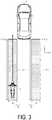
- detection areas Dr, Dl are set to either side behind the host vehicle C.
- the detection areas Dr, Dl are set symmetrically left to right with respect to the host vehicle C, a length L of each of the areas in a traveling direction (Y direction) is approximately 10 m, for example, and a length of each of the areas in a direction (X direction) orthogonal to the traveling direction ranges from approximately 0.7 to approximately 1.5 m, for example.
- these detection areas Dr, Dl are set at positions separated from the side surfaces of the vehicle by G (approximately 0.9 m). Note that numerical values described above are examples, and other numerical values are possible.
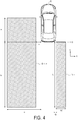
- FIG. 4 is a diagram for comparing a detection area in an operation mode for detecting a two-wheel vehicle with a detection area in a normal operation mode.
- the detection area in the normal operation mode is illustrated on a left side of FIG. 4
- the detection area in the operation mode for detecting a two-wheel vehicle is illustrated on a right side of FIG. 4 .
- the detection area Dln is set not only behind the vehicle, but also to either side of the vehicle.
- the detection area set to either side of the vehicle is referred to as an eyellipse.
- a 0.5 m
- b 2.0 m
- c 0.5 m
- the detection area in the operation mode for detecting a two-wheel vehicle mainly differs from the detection area in the normal mode in that a width is narrow, the eyellipse is not present, an end of the detection area closer to the vehicle is disposed at a position near the vehicle (i.e., c > G).
- the detection area for a four-wheel vehicle and a two-wheel vehicle illustrated in FIGS. 3 and 4 is given as one example, and the detection area having another shape is also possible.
- the calculation processing unit 13 After setting the detection areas Dl, Dr for detecting a two-wheel vehicle, the calculation processing unit 13 refers to information supplied from the other vehicle detection unit 11 and determines whether a two-wheel vehicle is present in the detection areas Dl, Dr. In a case that the calculation processing unit 13 determines that the two-wheel vehicle is present, the calculation processing unit 13 detects a position (X, Y) and a velocity (Vx, Vy) of the two-wheel vehicle B. Note that a position of the two-wheel vehicle B is indicated by a Cartesian coordinate system with a center of the host vehicle C as an origin.
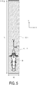
- FIG. 5 is a diagram illustrating a relationship between the two-wheel vehicle B and the detection area Dl. In FIG.
- the position (X, Y) of the two-wheel vehicle B is represented as a coordinate at a leading end of the two-wheel vehicle B.
- the velocity (Vx, Vy) of the two-wheel vehicle B is represented by a velocity in a X direction and a velocity in a Y direction of the two-wheel vehicle B.
- the example illustrated in FIG. 5 is one example, and another method may be employed to represent the position and velocity.
- the position (X, Y) of the two-wheel vehicle B may not be set at the leading end of the two-wheel vehicle B, and set at a center of the two-wheel vehicle B.
- the calculation processing unit 13 executes Time to Collision (TTC) line intersection determination using X, Y, Vx, and Vy found as described above.
- TTC Time to Collision
- the two-wheel vehicle B intersects the TTC line in a case that T ⁇ a TTC setting time is satisfied.
- the TTC setting time can be set to approximately 1.5 s, for example.
- a TTC setting time in the normal operation mode is approximately 5 s, for example.
- the calculation processing unit 13 switches from the normal operation mode for detecting a two-wheel vehicle or a four-wheel vehicle to the operation mode for detecting a two-wheel vehicle as illustrated in FIG. 3 .
- This enables the monitoring device 10 to issue a warning in a case that the two-wheel vehicle B will pass through either side of the host vehicle C. This can prevent the driver from changing direction without recognizing the two-wheel vehicle B traveling behind the host vehicle C and prevent the host vehicle C from colliding with the two-wheel vehicle B at a side of the host vehicle.
- step S10 the calculation processing unit 13 acquires a state of the host vehicle by referring to an output from the host vehicle state detection unit 12.
- the calculation processing unit 13 acquires information such as a vehicle speed, a yaw rate, a state of a transmission output from the host vehicle state detection unit 12.
- step S11 the calculation processing unit 13 determines whether a speed of the host vehicle is less than a predetermined threshold Th. In a case that the vehicle speed is less than the predetermined threshold Th (vehicle speed ⁇ Th) (YES in step S11), the process proceeds to step S13; otherwise (NO in step S11), the process proceeds to step S12. For example, in a case that a vehicle speed is less than 10 km/h, the determination in step S11 is YES, and the process proceeds to step S13.
- step S12 the calculation processing unit 13 executes a normal determination process. More specifically, the calculation processing unit 13 sets the detection area Dnl (see FIG. 4 ) and a detection area (Dnr (not illustrated)) for detecting both a four-wheel vehicle and a two-wheel vehicle, detects a target in the detection areas, and executes a normal process for determining whether the target will possibly collide with the host vehicle C.
- step S13 the calculation processing unit 13 refers to an output from the other vehicle detection unit 11 and determines whether the target is present at either side behind the host vehicle C. In a case that the calculation processing unit 13 determines that the target is present at either side behind the host vehicle C (YES in step S13), the process proceeds to step S14; otherwise (NO in step S13), the process proceeds to step S12.
- the calculation processing unit 13 determines that the target is present at either side behind the host vehicle C (YES), and the process proceeds to step S14.
- step S14 the calculation processing unit 13 refers to the state of the host vehicle C acquired in step S11 and determines whether a gear selector of the transmission of the host vehicle is shifted into a position other than "Reverse". In a case that the gear selector is shifted into a position other than "Reverse" (YES in step S14), the process proceeds to step S15; otherwise (NO in step S14), the process proceeds to step S12. For example, in a case that the gear selector is shifted into Drive (D), the process proceeds to step S15.
- step S15 the calculation processing unit 13 refers to the state of the host vehicle C acquired in step S11. In a case that the calculation processing unit 13 determines that the host vehicle C travels straight forward (YES in step S15), the process proceeds to step S16; otherwise (NO in step S15), the process proceeds to step S12. For example, in a case that a yaw rate obtained by referring to an output from the yaw axis sensor is 0.5 deg/s or less, the calculation processing unit 13 determines that the host vehicle C travels straight forward (YES), and the process proceeds to step S16.
- step S16 the calculation processing unit 13 sets a detection area corresponding to a two-wheel vehicle. More specifically, the calculation processing unit 13 sets the detection areas Dl, Dr, as illustrated in FIG. 3 , to either side behind the host vehicle C.
- step S17 the calculation processing unit 13 determines whether a two-wheel vehicle is present in the detection areas Dl, Dr. In a case that the calculation processing unit 13 determines that a two-wheel vehicle is present in the detection areas (YES in step S17), the process proceeds to step S18; otherwise (NO in step S17), the process proceeds to step S22.
- the two-wheel vehicle B is passing through a left side of the other vehicle C1 following the host vehicle and approaching the host vehicle C, the calculation processing unit 13 determines that the two-wheel vehicle B is present in the detection area D1 illustrated in FIG.3 , and the process proceeds to step S18.
- step S18 the calculation processing unit 13 calculates a position (X, Y) of the two-wheel vehicle detected in step S16. More specifically, the calculation processing unit 13 calculates the position (X, Y) of the two-wheel vehicle B illustrated in FIG. 2 as a coordinate point on a Cartesian coordinate system with a center of the host vehicle C as an origin.
- step S19 the calculation processing unit 13 calculates a velocity (Vx, Vy) of the two-wheel vehicle detected in step S16. More specifically, the calculation processing unit 13 calculates the velocity (Vx, Vy) of the two-wheel vehicle B illustrated in FIG. 2 .
- step S20 the calculation processing unit 13 determines whether the two-wheel vehicle B intersects the TTC line. In a case that the calculation processing unit 13 determines that the two-wheel vehicle B will intersect the TTC line (YES in step S20), the process proceeds to step S21; otherwise (NO in step S20), the process proceeds to step S22. More specifically, the calculation processing unit 13 determines whether the two-wheel vehicle B will intersect the TTC line using X, Y, Vx, and Vy found in the above process.
- step S21 the calculation processing unit 13 causes the warning unit 16 to issue a warning to attract attention of a driver or a passenger.
- step S22 the calculation processing unit 13 determines whether the process will be repeated. In a case that the calculation processing unit 13 determines that the process will be repeated (YES in step S22), the process returns to step S10, and a process similar to the above described process will be repeated; otherwise (NO in step S22), the process is terminated.
- a warning is issued in a case that the two-wheel vehicle B detected in the detection areas Dl, Dr is expected to intersect the TTC.
- a warning may be issued in a case that the two-wheel vehicle B is expected to intersect the TTC, and a driver operates a steering wheel or blinkers toward a lane where the two-wheel vehicle B travels. In such an embodiment, a side collision between the two-wheel vehicle B and the host vehicle changing direction can be prevented.
- a warning may be issued in a case that a driver or a passenger attempts to open a window or a door on a side where the two-wheel vehicle B passes through.
- a collision or a minor collision between the two-wheel vehicle B and hands or a door can be prevented in a case that a driver or a passenger puts his/her hands out of the window or opens the door.
- a warning may include blinking an LED, and generating a sound.
- the detection areas Dl, Dr having a fixed size are employed in the embodiment described above; however, a width W or a length L of the detection areas Dl, Dr maybe modified in accordance with a traveling speed of the host vehicle C or the like.
- the length L may be increased, or the width W may be increased as a speed of the host vehicle decreases.
- a decrease in a speed of the host vehicle means an increase in a relative speed in relation to the two-wheel vehicle B.
- Increasing L or W as a speed decreases allows a two-wheel vehicle present farther away to be detected and be set as a warning target.
- an example of the host vehicle C traveling at a low speed is given but, for example, for the host vehicle C being at rest due to a traffic jam, waiting for a traffic light, or the like, a warning may be issued in a case that a driver takes his/her foot off the brake pedal, presses on the gas pedal, or a gear selector is shifted from a neutral position into Drive (D).
- a warning may be issued in a case that a driver takes his/her foot off the brake pedal, presses on the gas pedal, or a gear selector is shifted from a neutral position into Drive (D).
- an example of a passing two-wheel vehicle is given but, for example, an object other than a two-wheel vehicle (e.g., a wheelchair, a walking aid vehicle, a tricycle, or a pedestrian) may be detected.
- an object other than a two-wheel vehicle e.g., a wheelchair, a walking aid vehicle, a tricycle, or a pedestrian
- determinations are made in accordance with a state at that point but, a history of past information may be stored, and determinations may be made in accordance with the history. This method can prevent the occurrence of an erroneous determination even in a case where conditions on a road rapidly change.
- a warning is issued only in the host vehicle in a case that the two-wheel vehicle passing by the host vehicle is detected, but for example, for vehicles capable of executing an inter-vehicle communication, the host vehicle may notify an adjacent vehicle of the two-wheel vehicle passing by the host vehicle, and attract an attention of the driver of the adjacent vehicle.
- a radar device configured to emit electric waves to detect an object is employed as the other vehicle detection unit 11, but the object may be detected by a method other than using the electric waves.
- an object may be detected by emitting ultrasonic waves and analyzing a reflected wave thereof, or by emitting light such as infrared light or ultraviolet light and analyzing the reflected wave thereof.
- a camera may be employed to capture an image around a vehicle, and the processes may be performed by extracting an image of an area corresponding to the detection area from the captured image.
- step S13 of the flowchart illustrated in FIG. 6 whether the target is present at either side behind the vehicle is determined, but the process may be omitted and the detection area may be selected on the basis of a vehicle speed, a state of a gear, or whether the vehicle travels straight forward.
- a warning may not be issued depending on settings by a passenger.
- a target approaching from 10 m behind the host vehicle in 3 seconds or greater a target traveling at a less than 3.33 m/s speed
- the target is considered to be a pedestrian walking around the vehicle or the like.
- a warning is issued against such a target, the process may be complicated depending on a usage environment. For this reason, a warning may not be issued depending on settings by a passenger.
Landscapes
- Engineering & Computer Science (AREA)
- Remote Sensing (AREA)
- Radar, Positioning & Navigation (AREA)
- Physics & Mathematics (AREA)
- General Physics & Mathematics (AREA)
- Mechanical Engineering (AREA)
- Automation & Control Theory (AREA)
- Computer Networks & Wireless Communication (AREA)
- Transportation (AREA)
- Electromagnetism (AREA)
- Business, Economics & Management (AREA)
- Emergency Management (AREA)
- Human Computer Interaction (AREA)
- Traffic Control Systems (AREA)
- Emergency Alarm Devices (AREA)
Applications Claiming Priority (2)
| Application Number | Priority Date | Filing Date | Title |
|---|---|---|---|
| JP2015220801 | 2015-11-10 | ||
| PCT/JP2016/083440 WO2017082370A1 (ja) | 2015-11-10 | 2016-11-10 | 監視装置および監視方法 |
Publications (3)
| Publication Number | Publication Date |
|---|---|
| EP3376486A1 true EP3376486A1 (de) | 2018-09-19 |
| EP3376486A4 EP3376486A4 (de) | 2019-01-09 |
| EP3376486B1 EP3376486B1 (de) | 2023-05-10 |
Family
ID=58696129
Family Applications (1)
| Application Number | Title | Priority Date | Filing Date |
|---|---|---|---|
| EP16864331.0A Active EP3376486B1 (de) | 2015-11-10 | 2016-11-10 | Überwachungsvorrichtung und überwachungsverfahren |
Country Status (5)
| Country | Link |
|---|---|
| US (1) | US10901078B2 (de) |
| EP (1) | EP3376486B1 (de) |
| JP (1) | JP6757738B2 (de) |
| CN (1) | CN108352120B (de) |
| WO (1) | WO2017082370A1 (de) |
Families Citing this family (12)
| Publication number | Priority date | Publication date | Assignee | Title |
|---|---|---|---|---|
| DE102017219902A1 (de) * | 2017-11-09 | 2019-05-09 | Robert Bosch Gmbh | Verfahren und Steuergerät zur Totwinkelüberwachung an einem Zweirad |
| US20180215377A1 (en) * | 2018-03-29 | 2018-08-02 | GM Global Technology Operations LLC | Bicycle and motorcycle protection behaviors |
| JP7123243B2 (ja) * | 2019-03-29 | 2022-08-22 | 本田技研工業株式会社 | 情報提供装置および該装置を有する車両 |
| JP6896023B2 (ja) * | 2019-07-02 | 2021-06-30 | 三菱電機株式会社 | 車両用接近報知システム及び車両用接近報知方法 |
| CN114365208B (zh) * | 2019-09-18 | 2023-08-08 | 本田技研工业株式会社 | 驾驶辅助装置、驾驶辅助方法以及存储介质 |
| JP6887471B2 (ja) * | 2019-09-20 | 2021-06-16 | 三菱電機株式会社 | 車両用後側方警報装置 |
| CN110949381B (zh) * | 2019-11-12 | 2021-02-12 | 深圳大学 | 一种驾驶行为危险度的监测方法及装置 |
| JP7350099B2 (ja) * | 2020-01-31 | 2023-09-25 | 三菱電機株式会社 | 先行車判定装置及び先行車判定プログラム |
| US11535246B2 (en) * | 2020-03-30 | 2022-12-27 | Denso Corporation | Systems and methods for providing a warning to an occupant of a vehicle |
| JP2022151314A (ja) | 2021-03-26 | 2022-10-07 | パナソニックIpマネジメント株式会社 | 制御装置、警告制御方法およびプログラム |
| RO137337A2 (ro) * | 2021-09-30 | 2023-03-30 | Toyota Jidosha Kabushiki Kaisha | Aparat de asistenţă pentru ieşirea dintr-un vehicul |
| US20230316267A1 (en) * | 2022-04-01 | 2023-10-05 | Dr. Ing. H.C. F. Porsche Aktiengesellschaft | Vehicle data sharing for collaborative driving experience |
Family Cites Families (15)
| Publication number | Priority date | Publication date | Assignee | Title |
|---|---|---|---|---|
| JP3262001B2 (ja) * | 1996-12-09 | 2002-03-04 | 三菱自動車工業株式会社 | 車両の後側方警報装置 |
| JPH10166974A (ja) | 1996-12-09 | 1998-06-23 | Mitsubishi Motors Corp | 車両の後側方警報装置 |
| JP3324421B2 (ja) * | 1996-12-09 | 2002-09-17 | 三菱自動車工業株式会社 | 車両の後側方警報装置 |
| US6268803B1 (en) * | 1998-08-06 | 2001-07-31 | Altra Technologies Incorporated | System and method of avoiding collisions |
| JP3936713B2 (ja) | 2004-09-24 | 2007-06-27 | 三菱電機株式会社 | 車両用後側方警報装置 |
| JP2007062641A (ja) * | 2005-09-01 | 2007-03-15 | Yamaha Corp | 自動車用障害物検知装置 |
| JP4967603B2 (ja) * | 2006-11-01 | 2012-07-04 | スズキ株式会社 | 車両の後側方監視装置 |
| JP2008172441A (ja) * | 2007-01-10 | 2008-07-24 | Omron Corp | 検出装置および方法、並びに、プログラム |
| JP5463919B2 (ja) * | 2010-01-07 | 2014-04-09 | マツダ株式会社 | 車両の後側方警報装置 |
| CN103718214B (zh) * | 2011-08-02 | 2017-08-11 | 日产自动车株式会社 | 移动体检测装置和移动体检测方法 |
| JP5637506B2 (ja) * | 2011-09-26 | 2014-12-10 | トヨタ自動車株式会社 | 後側方接近警報装置 |
| DE102012213568A1 (de) * | 2012-08-01 | 2014-02-06 | Robert Bosch Gmbh | Sicherheitseinrichtung für kraftfahrzeuge |
| JP6011791B2 (ja) * | 2012-10-24 | 2016-10-19 | 三菱自動車工業株式会社 | 車両用後方監視装置 |
| JP6413240B2 (ja) | 2014-01-08 | 2018-10-31 | 株式会社デンソー | 車両制御装置および車両 |
| SE540271C2 (sv) * | 2014-04-01 | 2018-05-22 | Scania Cv Ab | Förfarande för att riskbedöma körfältsbyte vid framförande av ett ledande fordon på en vägbana med åtminstone två angränsande körfält |
-
2016
- 2016-11-10 JP JP2017550404A patent/JP6757738B2/ja active Active
- 2016-11-10 EP EP16864331.0A patent/EP3376486B1/de active Active
- 2016-11-10 WO PCT/JP2016/083440 patent/WO2017082370A1/ja active Application Filing
- 2016-11-10 CN CN201680065386.1A patent/CN108352120B/zh active Active
-
2018
- 2018-05-09 US US15/974,935 patent/US10901078B2/en active Active
Also Published As
| Publication number | Publication date |
|---|---|
| EP3376486A4 (de) | 2019-01-09 |
| CN108352120B (zh) | 2021-10-29 |
| US20180259636A1 (en) | 2018-09-13 |
| WO2017082370A1 (ja) | 2017-05-18 |
| JP6757738B2 (ja) | 2020-09-23 |
| EP3376486B1 (de) | 2023-05-10 |
| JPWO2017082370A1 (ja) | 2018-10-04 |
| CN108352120A (zh) | 2018-07-31 |
| US10901078B2 (en) | 2021-01-26 |
Similar Documents
| Publication | Publication Date | Title |
|---|---|---|
| EP3376486B1 (de) | Überwachungsvorrichtung und überwachungsverfahren | |
| US8493195B2 (en) | Method for detecting an environment of a vehicle | |
| JP5163991B2 (ja) | 複雑な交通状況における車両の速度制御方法 | |
| JP4628683B2 (ja) | 歩行者検出装置、及び、その歩行者検出装置を備えた車両用運転支援装置 | |
| JP5949961B2 (ja) | 運転支援装置 | |
| JP2023175741A (ja) | 受動型赤外線歩行者検出および回避システム | |
| US11465616B2 (en) | Cross traffic alert with flashing indicator recognition | |
| JP2010030513A (ja) | 車両の運転支援装置 | |
| JP2011248855A (ja) | 車両用衝突警報装置 | |
| WO2005092667A1 (ja) | 車両の警報装置 | |
| JP2011210102A (ja) | 車両用運転支援装置 | |
| JP2011048641A (ja) | 物体検出装置及び運転支援装置 | |
| JP6079724B2 (ja) | 運転支援装置 | |
| JP6589840B2 (ja) | 運転支援装置 | |
| EP3438947A1 (de) | Überwachungsvorrichtung und überwachungsverfahren | |
| JP2005173703A (ja) | 交差点衝突予防装置 | |
| JP2008046845A (ja) | 割込車両判定装置 | |
| JP2018122627A (ja) | 車両制御装置 | |
| JP2008299779A (ja) | 移動体接近報知装置 | |
| JP5146288B2 (ja) | 車両制御装置 | |
| JP5444941B2 (ja) | 物体検出装置 | |
| JP2004280453A (ja) | 車両の右折時安全確認システム | |
| JP5582310B2 (ja) | 車両の運転支援装置 | |
| JP2010198513A (ja) | 前方車両横移動警告装置 | |
| JP4788357B2 (ja) | 運転者心理判定装置 |
Legal Events
| Date | Code | Title | Description |
|---|---|---|---|
| STAA | Information on the status of an ep patent application or granted ep patent |
Free format text: STATUS: THE INTERNATIONAL PUBLICATION HAS BEEN MADE |
|
| PUAI | Public reference made under article 153(3) epc to a published international application that has entered the european phase |
Free format text: ORIGINAL CODE: 0009012 |
|
| STAA | Information on the status of an ep patent application or granted ep patent |
Free format text: STATUS: REQUEST FOR EXAMINATION WAS MADE |
|
| 17P | Request for examination filed |
Effective date: 20180509 |
|
| AK | Designated contracting states |
Kind code of ref document: A1 Designated state(s): AL AT BE BG CH CY CZ DE DK EE ES FI FR GB GR HR HU IE IS IT LI LT LU LV MC MK MT NL NO PL PT RO RS SE SI SK SM TR |
|
| AX | Request for extension of the european patent |
Extension state: BA ME |
|
| A4 | Supplementary search report drawn up and despatched |
Effective date: 20181211 |
|
| RIC1 | Information provided on ipc code assigned before grant |
Ipc: G08G 1/16 20060101AFI20181205BHEP Ipc: B60R 21/00 20060101ALI20181205BHEP Ipc: G08B 21/00 20060101ALI20181205BHEP Ipc: B60R 21/34 20110101ALI20181205BHEP |
|
| DAV | Request for validation of the european patent (deleted) | ||
| DAX | Request for extension of the european patent (deleted) | ||
| STAA | Information on the status of an ep patent application or granted ep patent |
Free format text: STATUS: EXAMINATION IS IN PROGRESS |
|
| 17Q | First examination report despatched |
Effective date: 20201016 |
|
| STAA | Information on the status of an ep patent application or granted ep patent |
Free format text: STATUS: EXAMINATION IS IN PROGRESS |
|
| STAA | Information on the status of an ep patent application or granted ep patent |
Free format text: STATUS: EXAMINATION IS IN PROGRESS |
|
| REG | Reference to a national code |
Ref country code: DE Ref legal event code: R079 Ref document number: 602016079407 Country of ref document: DE Free format text: PREVIOUS MAIN CLASS: G08G0001160000 Ipc: B60W0030080000 |
|
| GRAP | Despatch of communication of intention to grant a patent |
Free format text: ORIGINAL CODE: EPIDOSNIGR1 |
|
| STAA | Information on the status of an ep patent application or granted ep patent |
Free format text: STATUS: GRANT OF PATENT IS INTENDED |
|
| RIC1 | Information provided on ipc code assigned before grant |
Ipc: G01S 13/931 20200101ALI20221107BHEP Ipc: G08B 21/00 20060101ALI20221107BHEP Ipc: B60R 21/34 20110101ALI20221107BHEP Ipc: B60R 21/00 20060101ALI20221107BHEP Ipc: G08G 1/16 20060101ALI20221107BHEP Ipc: B60W 50/14 20120101ALI20221107BHEP Ipc: B60W 30/095 20120101ALI20221107BHEP Ipc: B60W 30/08 20120101AFI20221107BHEP |
|
| INTG | Intention to grant announced |
Effective date: 20221129 |
|
| GRAS | Grant fee paid |
Free format text: ORIGINAL CODE: EPIDOSNIGR3 |
|
| GRAA | (expected) grant |
Free format text: ORIGINAL CODE: 0009210 |
|
| STAA | Information on the status of an ep patent application or granted ep patent |
Free format text: STATUS: THE PATENT HAS BEEN GRANTED |
|
| AK | Designated contracting states |
Kind code of ref document: B1 Designated state(s): AL AT BE BG CH CY CZ DE DK EE ES FI FR GB GR HR HU IE IS IT LI LT LU LV MC MK MT NL NO PL PT RO RS SE SI SK SM TR |
|
| REG | Reference to a national code |
Ref country code: GB Ref legal event code: FG4D |
|
| REG | Reference to a national code |
Ref country code: AT Ref legal event code: REF Ref document number: 1566415 Country of ref document: AT Kind code of ref document: T Effective date: 20230515 Ref country code: CH Ref legal event code: EP |
|
| REG | Reference to a national code |
Ref country code: DE Ref legal event code: R096 Ref document number: 602016079407 Country of ref document: DE |
|
| REG | Reference to a national code |
Ref country code: IE Ref legal event code: FG4D |
|
| P01 | Opt-out of the competence of the unified patent court (upc) registered |
Effective date: 20230414 |
|
| REG | Reference to a national code |
Ref country code: LT Ref legal event code: MG9D |
|
| REG | Reference to a national code |
Ref country code: NL Ref legal event code: MP Effective date: 20230510 |
|
| REG | Reference to a national code |
Ref country code: AT Ref legal event code: MK05 Ref document number: 1566415 Country of ref document: AT Kind code of ref document: T Effective date: 20230510 |
|
| PG25 | Lapsed in a contracting state [announced via postgrant information from national office to epo] |
Ref country code: SE Free format text: LAPSE BECAUSE OF FAILURE TO SUBMIT A TRANSLATION OF THE DESCRIPTION OR TO PAY THE FEE WITHIN THE PRESCRIBED TIME-LIMIT Effective date: 20230510 Ref country code: PT Free format text: LAPSE BECAUSE OF FAILURE TO SUBMIT A TRANSLATION OF THE DESCRIPTION OR TO PAY THE FEE WITHIN THE PRESCRIBED TIME-LIMIT Effective date: 20230911 Ref country code: NO Free format text: LAPSE BECAUSE OF FAILURE TO SUBMIT A TRANSLATION OF THE DESCRIPTION OR TO PAY THE FEE WITHIN THE PRESCRIBED TIME-LIMIT Effective date: 20230810 Ref country code: NL Free format text: LAPSE BECAUSE OF FAILURE TO SUBMIT A TRANSLATION OF THE DESCRIPTION OR TO PAY THE FEE WITHIN THE PRESCRIBED TIME-LIMIT Effective date: 20230510 Ref country code: ES Free format text: LAPSE BECAUSE OF FAILURE TO SUBMIT A TRANSLATION OF THE DESCRIPTION OR TO PAY THE FEE WITHIN THE PRESCRIBED TIME-LIMIT Effective date: 20230510 Ref country code: AT Free format text: LAPSE BECAUSE OF FAILURE TO SUBMIT A TRANSLATION OF THE DESCRIPTION OR TO PAY THE FEE WITHIN THE PRESCRIBED TIME-LIMIT Effective date: 20230510 |
|
| PG25 | Lapsed in a contracting state [announced via postgrant information from national office to epo] |
Ref country code: RS Free format text: LAPSE BECAUSE OF FAILURE TO SUBMIT A TRANSLATION OF THE DESCRIPTION OR TO PAY THE FEE WITHIN THE PRESCRIBED TIME-LIMIT Effective date: 20230510 Ref country code: PL Free format text: LAPSE BECAUSE OF FAILURE TO SUBMIT A TRANSLATION OF THE DESCRIPTION OR TO PAY THE FEE WITHIN THE PRESCRIBED TIME-LIMIT Effective date: 20230510 Ref country code: LV Free format text: LAPSE BECAUSE OF FAILURE TO SUBMIT A TRANSLATION OF THE DESCRIPTION OR TO PAY THE FEE WITHIN THE PRESCRIBED TIME-LIMIT Effective date: 20230510 Ref country code: LT Free format text: LAPSE BECAUSE OF FAILURE TO SUBMIT A TRANSLATION OF THE DESCRIPTION OR TO PAY THE FEE WITHIN THE PRESCRIBED TIME-LIMIT Effective date: 20230510 Ref country code: IS Free format text: LAPSE BECAUSE OF FAILURE TO SUBMIT A TRANSLATION OF THE DESCRIPTION OR TO PAY THE FEE WITHIN THE PRESCRIBED TIME-LIMIT Effective date: 20230910 Ref country code: HR Free format text: LAPSE BECAUSE OF FAILURE TO SUBMIT A TRANSLATION OF THE DESCRIPTION OR TO PAY THE FEE WITHIN THE PRESCRIBED TIME-LIMIT Effective date: 20230510 Ref country code: GR Free format text: LAPSE BECAUSE OF FAILURE TO SUBMIT A TRANSLATION OF THE DESCRIPTION OR TO PAY THE FEE WITHIN THE PRESCRIBED TIME-LIMIT Effective date: 20230811 |
|
| PG25 | Lapsed in a contracting state [announced via postgrant information from national office to epo] |
Ref country code: FI Free format text: LAPSE BECAUSE OF FAILURE TO SUBMIT A TRANSLATION OF THE DESCRIPTION OR TO PAY THE FEE WITHIN THE PRESCRIBED TIME-LIMIT Effective date: 20230510 |
|
| PG25 | Lapsed in a contracting state [announced via postgrant information from national office to epo] |
Ref country code: SK Free format text: LAPSE BECAUSE OF FAILURE TO SUBMIT A TRANSLATION OF THE DESCRIPTION OR TO PAY THE FEE WITHIN THE PRESCRIBED TIME-LIMIT Effective date: 20230510 |
|
| PG25 | Lapsed in a contracting state [announced via postgrant information from national office to epo] |
Ref country code: SM Free format text: LAPSE BECAUSE OF FAILURE TO SUBMIT A TRANSLATION OF THE DESCRIPTION OR TO PAY THE FEE WITHIN THE PRESCRIBED TIME-LIMIT Effective date: 20230510 Ref country code: SK Free format text: LAPSE BECAUSE OF FAILURE TO SUBMIT A TRANSLATION OF THE DESCRIPTION OR TO PAY THE FEE WITHIN THE PRESCRIBED TIME-LIMIT Effective date: 20230510 Ref country code: RO Free format text: LAPSE BECAUSE OF FAILURE TO SUBMIT A TRANSLATION OF THE DESCRIPTION OR TO PAY THE FEE WITHIN THE PRESCRIBED TIME-LIMIT Effective date: 20230510 Ref country code: EE Free format text: LAPSE BECAUSE OF FAILURE TO SUBMIT A TRANSLATION OF THE DESCRIPTION OR TO PAY THE FEE WITHIN THE PRESCRIBED TIME-LIMIT Effective date: 20230510 Ref country code: DK Free format text: LAPSE BECAUSE OF FAILURE TO SUBMIT A TRANSLATION OF THE DESCRIPTION OR TO PAY THE FEE WITHIN THE PRESCRIBED TIME-LIMIT Effective date: 20230510 Ref country code: CZ Free format text: LAPSE BECAUSE OF FAILURE TO SUBMIT A TRANSLATION OF THE DESCRIPTION OR TO PAY THE FEE WITHIN THE PRESCRIBED TIME-LIMIT Effective date: 20230510 |
|
| PGFP | Annual fee paid to national office [announced via postgrant information from national office to epo] |
Ref country code: DE Payment date: 20230929 Year of fee payment: 8 |
|
| REG | Reference to a national code |
Ref country code: DE Ref legal event code: R097 Ref document number: 602016079407 Country of ref document: DE |
|
| PLBE | No opposition filed within time limit |
Free format text: ORIGINAL CODE: 0009261 |
|
| STAA | Information on the status of an ep patent application or granted ep patent |
Free format text: STATUS: NO OPPOSITION FILED WITHIN TIME LIMIT |
|
| 26N | No opposition filed |
Effective date: 20240213 |
|
| PG25 | Lapsed in a contracting state [announced via postgrant information from national office to epo] |
Ref country code: SI Free format text: LAPSE BECAUSE OF FAILURE TO SUBMIT A TRANSLATION OF THE DESCRIPTION OR TO PAY THE FEE WITHIN THE PRESCRIBED TIME-LIMIT Effective date: 20230510 |