EP3369466B1 - Spielsystem, spielvorrichtung, spielprogramm und spielverfahren - Google Patents
Spielsystem, spielvorrichtung, spielprogramm und spielverfahren Download PDFInfo
- Publication number
- EP3369466B1 EP3369466B1 EP17189617.8A EP17189617A EP3369466B1 EP 3369466 B1 EP3369466 B1 EP 3369466B1 EP 17189617 A EP17189617 A EP 17189617A EP 3369466 B1 EP3369466 B1 EP 3369466B1
- Authority
- EP
- European Patent Office
- Prior art keywords
- game
- game controller
- controller
- orientation
- data
- Prior art date
- Legal status (The legal status is an assumption and is not a legal conclusion. Google has not performed a legal analysis and makes no representation as to the accuracy of the status listed.)
- Active
Links
Images


Classifications
-
- A—HUMAN NECESSITIES
- A63—SPORTS; GAMES; AMUSEMENTS
- A63F—CARD, BOARD, OR ROULETTE GAMES; INDOOR GAMES USING SMALL MOVING PLAYING BODIES; VIDEO GAMES; GAMES NOT OTHERWISE PROVIDED FOR
- A63F13/00—Video games, i.e. games using an electronically generated display having two or more dimensions
- A63F13/20—Input arrangements for video game devices
- A63F13/21—Input arrangements for video game devices characterised by their sensors, purposes or types
- A63F13/211—Input arrangements for video game devices characterised by their sensors, purposes or types using inertial sensors, e.g. accelerometers or gyroscopes
-
- A—HUMAN NECESSITIES
- A63—SPORTS; GAMES; AMUSEMENTS
- A63F—CARD, BOARD, OR ROULETTE GAMES; INDOOR GAMES USING SMALL MOVING PLAYING BODIES; VIDEO GAMES; GAMES NOT OTHERWISE PROVIDED FOR
- A63F13/00—Video games, i.e. games using an electronically generated display having two or more dimensions
- A63F13/20—Input arrangements for video game devices
- A63F13/24—Constructional details thereof, e.g. game controllers with detachable joystick handles
-
- A—HUMAN NECESSITIES
- A63—SPORTS; GAMES; AMUSEMENTS
- A63F—CARD, BOARD, OR ROULETTE GAMES; INDOOR GAMES USING SMALL MOVING PLAYING BODIES; VIDEO GAMES; GAMES NOT OTHERWISE PROVIDED FOR
- A63F13/00—Video games, i.e. games using an electronically generated display having two or more dimensions
- A63F13/25—Output arrangements for video game devices
-
- A—HUMAN NECESSITIES
- A63—SPORTS; GAMES; AMUSEMENTS
- A63F—CARD, BOARD, OR ROULETTE GAMES; INDOOR GAMES USING SMALL MOVING PLAYING BODIES; VIDEO GAMES; GAMES NOT OTHERWISE PROVIDED FOR
- A63F13/00—Video games, i.e. games using an electronically generated display having two or more dimensions
- A63F13/40—Processing input control signals of video game devices, e.g. signals generated by the player or derived from the environment
- A63F13/42—Processing input control signals of video game devices, e.g. signals generated by the player or derived from the environment by mapping the input signals into game commands, e.g. mapping the displacement of a stylus on a touch screen to the steering angle of a virtual vehicle
- A63F13/428—Processing input control signals of video game devices, e.g. signals generated by the player or derived from the environment by mapping the input signals into game commands, e.g. mapping the displacement of a stylus on a touch screen to the steering angle of a virtual vehicle involving motion or position input signals, e.g. signals representing the rotation of an input controller or a player's arm motions sensed by accelerometers or gyroscopes
-
- A—HUMAN NECESSITIES
- A63—SPORTS; GAMES; AMUSEMENTS
- A63F—CARD, BOARD, OR ROULETTE GAMES; INDOOR GAMES USING SMALL MOVING PLAYING BODIES; VIDEO GAMES; GAMES NOT OTHERWISE PROVIDED FOR
- A63F13/00—Video games, i.e. games using an electronically generated display having two or more dimensions
- A63F13/80—Special adaptations for executing a specific game genre or game mode
- A63F13/833—Hand-to-hand fighting, e.g. martial arts competition
-
- A—HUMAN NECESSITIES
- A63—SPORTS; GAMES; AMUSEMENTS
- A63F—CARD, BOARD, OR ROULETTE GAMES; INDOOR GAMES USING SMALL MOVING PLAYING BODIES; VIDEO GAMES; GAMES NOT OTHERWISE PROVIDED FOR
- A63F13/00—Video games, i.e. games using an electronically generated display having two or more dimensions
- A63F13/90—Constructional details or arrangements of video game devices not provided for in groups A63F13/20 or A63F13/25, e.g. housing, wiring, connections or cabinets
- A63F13/92—Video game devices specially adapted to be hand-held while playing
-
- A—HUMAN NECESSITIES
- A63—SPORTS; GAMES; AMUSEMENTS
- A63F—CARD, BOARD, OR ROULETTE GAMES; INDOOR GAMES USING SMALL MOVING PLAYING BODIES; VIDEO GAMES; GAMES NOT OTHERWISE PROVIDED FOR
- A63F13/00—Video games, i.e. games using an electronically generated display having two or more dimensions
- A63F13/90—Constructional details or arrangements of video game devices not provided for in groups A63F13/20 or A63F13/25, e.g. housing, wiring, connections or cabinets
- A63F13/98—Accessories, i.e. detachable arrangements optional for the use of the video game device, e.g. grip supports of game controllers
Definitions
- the present invention relates to a game system, a game apparatus, a game program, and a game processing method in which an operation can be performed using a game controller.
- Patent Literature 1 Japanese Unexamined Patent Application Publication No. 2012-162
- Patent Literature 1 Japanese Unexamined Patent Application Publication No. 2012-162
- EP 3 103 532 A2 describes game controller comprising a housing, a directional input section and operation sections.
- the housing has a shape elongated in a predetermined direction, the housing having several surfaces.
- the directional input section and a first, second, third and fourth operation section are on different surfaces and/or positions of the housing.
- US 2015/084900 A1 describes a removable input module for a touch-screen device.
- the input module comprises an attachment mechanism to attach the module to the touch-screen device, one or more input controls and an accelerometer and/or magnetometer.
- the accelerometer and/or magnetometer are for providing signals that may be used to determine the orientation of the input module relative to the touch-screen device and/or to another input module which is attached to the same touch-screen device.
- the invention is defined by the appended set of claims.
- the independent claims define a game apparatus, a game program, and a game processing method that are capable of specifying whether a game controller is attached to an attachment.
- Preferred embodiments of the invention are described in the dependent claims.
- a game system includes a first game controller, a second game controller, an attachment to which the first game controller and the second game controller are attachable, and a game apparatus capable of communicating with the first game controller and the second game controller.
- the first game controller includes a first motion/orientation sensor and a first transmission means.
- the first motion/orientation sensor outputs first data corresponding to at least one of a motion and an orientation of the first game controller.
- the first transmission means transmits, to the game apparatus, the first data output from the first motion/orientation sensor.
- the second game controller includes a second motion/orientation sensor and second transmission means.
- the second motion/orientation sensor outputs second data corresponding to at least one of a motion and an orientation of the second game controller.
- the second transmission means transmits, to the game apparatus, the second data output from the second motion/orientation sensor.
- the game apparatus includes reception means, reception means, and game processing means.
- the reception means receives the first data and the second data.
- the determination means based on the first data and the second data, determines whether or not the first game controller and the second game controller are attached to the attachment.
- the game processing means based on at least the result of the determination by the determination means, performs game processing.
- first motion/orientation sensor may be an angular velocity sensor for detecting an angular velocity generated in the first game controller.
- the second motion/orientation sensor may be an angular velocity sensor for detecting an angular velocity generated in the second game controller.
- the determination means may include first orientation calculation means and second orientation calculation means.
- the first orientation calculation means based on an angular velocity corresponding to the first data, calculates a first orientation of the first game controller.
- the second orientation calculation means based on an angular velocity corresponding to the second data, calculates a second orientation of the second game controller. In this case, based on the first orientation and the second orientation, the determination means may determine whether or not the first game controller and the second game controller are attached to the attachment.
- the determination means may determine that the first game controller and the second game controller are attached to the attachment.
- the determination means may determine that the first game controller and the second game controller are attached to the attachment.
- the determination means may further include first parameter calculation means and second parameter calculation means.
- the first parameter calculation means in accordance with an angular velocity based on the first data, calculates a first parameter indicating at least one of the motion and the orientation of the first game controller and different from the first orientation.
- the second parameter calculation means in accordance with an angular velocity based on the second data, calculates a second parameter indicating at least one of the motion and the orientation of the second game controller and different from the second orientation.
- the determination means may determine whether or not the first game controller and the second game controller are attached to the attachment.
- the first game controller may further include a third motion/orientation sensor.
- the third motion/orientation sensor outputs third data corresponding to at least one of the motion and the orientation of the first game controller, the third motion/orientation sensor being different from the first motion/orientation sensor.
- the first transmission means may further transmit, to the game apparatus, the third data output from the third motion/orientation sensor.
- the second game controller may further include a fourth motion/orientation sensor.
- the fourth motion/orientation sensor outputs fourth data corresponding to at least one of the motion and the orientation of the second game controller, the fourth motion/orientation sensor being different from the second motion/orientation sensor.
- the second transmission means may further transmit, to the game apparatus, the fourth data output from the fourth motion/orientation sensor.
- the reception means may further receive the third data and the fourth data. Based on the third data and the fourth data in addition to the first data and the second data, the determination means may determine whether or not the first game controller and the second game controller are attached to the attachment.
- the third data transmitted from the first transmission means may be data itself output from the third motion/orientation sensor, or data obtained by processing data output by the third motion/orientation sensor for transmission and reception and the like.
- the fourth data transmitted from the second transmission means may be data output itself from the fourth motion/orientation sensor, or may be data obtained by processing data output from the fourth motion/orientation sensor for transmission and reception and the like.
- the first motion/orientation sensor may be an angular velocity sensor for detecting an angular velocity generated in the first game controller.
- the second motion/orientation sensor may be an angular velocity sensor for detecting an angular velocity generated in the second game controller.
- the third motion/orientation sensor may be an acceleration sensor for detecting an acceleration generated in the first game controller.
- the fourth motion/orientation sensor may be an acceleration sensor for detecting an acceleration generated in the second game controller.
- the determination means may maintain a result of a determination before the condition is satisfied.
- the determination means may determine that the first game controller and the second game controller are attached to the attachment.
- the determination means may determine that the first game controller and the second game controller are attached to the attachment.
- the determination means may repeatedly perform a determination process for determining whether or not the first game controller and the second game controller are attached to the attachment.
- the game processing means may perform the game processing based on a first operation mode
- the determination means determines that the first game controller and the second game controller are attached to the attachment
- the game processing means may perform the game processing based on a second operation mode.
- the determination means may maintain the result of the determination that the first game controller and the second game controller are not attached to the attachment.
- the game processing means may perform the game processing based on a first operation mode, and when the determination means determines that the first game controller and the second game controller are attached to the attachment, the game processing means may perform the game processing based on a second operation mode.
- different game processing can be performed based on whether the game controllers are operated in the state where the game controllers are attached to an attachment, or the game controllers are operated in the state where the game controllers are not attached to the attachment.
- the game processing means may perform game processing in accordance with a first operation performed on the first game controller and/or the second game controller, and when the second operation mode is set, the game processing means may perform the game processing in accordance with a second operation different from the first operation performed on the first game controller and/or the second game controller.
- the game processing means may perform game processing in accordance with a third operation performed on the first game controller and/or the second game controller, and when the second operation mode is set, the game processing means may perform game processing different from the game processing in accordance with the third operation performed on the first game controller and/or the second game controller.
- the first transmission means may transmit first operation data corresponding to an operation performed on the first game controller, together with the first data to the game apparatus.
- the second transmission means may transmit second operation data corresponding to an operation performed on the second game controller, together with the second data to the game apparatus.
- the reception means may receive the first data, the second data, the first operation data, and the second operation data. Based on the result of the determination by the determination means, and the first operation data and the second operation data, the game processing means may perform the game processing.
- the determination means may include first motion calculation means and second motion calculation means.
- the first motion calculation means based on the first data, calculates the motion of the first game controller.
- the second motion calculation means based on the second data, calculates the motion of the second game controller. In this case, when the motion of the first game controller and the motion of the second game controller are the same as each other, the determination means may determine that the first game controller and the second game controller are attached to the attachment.
- first motion/orientation sensor may be an angular velocity sensor for detecting an angular velocity generated in the first game controller.
- the second motion/orientation sensor may be an angular velocity sensor for detecting an angular velocity generated in the second game controller.
- the first motion calculation means may calculate, as the motion of the first game controller, the angular velocity generated in the first game controller.
- the second motion calculation means may calculate, as the motion of the second game controller, the angular velocity generated in the second game controller.
- the present invention may be carried out in the forms of a game apparatus, a game program, and a game processing method.
- the present invention it is possible to determine whether a game controller is operated in the state where the game controller is attached to an attachment, or the game controller is operated in the state where the game controller is not attached to the attachment.
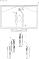
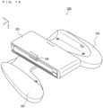
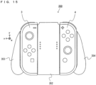
- An example of a game system 1 according to the exemplary embodiment includes a main body apparatus (an information processing apparatus; which functions as a game apparatus main body in the exemplary embodiment) 2, a left controller 3, and a right controller 4.
- a main body apparatus an information processing apparatus; which functions as a game apparatus main body in the exemplary embodiment
- a left controller 3 and a right controller 4 are attachable to and detachable from the main body apparatus 2. That is, the game system 1 can be used as a unified apparatus obtained by attaching each of the left controller 3 and the right controller 4 to the main body apparatus 2.
- the main body apparatus 2, the left controller 3, and the right controller 4 can also be used as separate bodies (see FIG. 2 ).
- the hardware configuration of the game system 1 according to the exemplary embodiment is described, and then, the control of the game system 1 according to the exemplary embodiment is described.
- FIG. 1 is a diagram showing an example of the state where the left controller 3 and the right controller 4 are attached to the main body apparatus 2. As shown in FIG. 1 , each of the left controller 3 and the right controller 4 is attached to and unified with the main body apparatus 2.
- the main body apparatus 2 is an apparatus for performing various processes (e.g., game processing) in the game system 1.
- the main body apparatus 2 includes a display 12.
- Each of the left controller 3 and the right controller 4 is an apparatus including operation sections with which a user provides inputs.
- FIG. 2 is a diagram showing an example of the state where each of the left controller 3 and the right controller 4 is detached from the main body apparatus 2. As shown in FIGS. 1 and 2 , the left controller 3 and the right controller 4 are attachable to and detachable from the main body apparatus 2. It should be noted that hereinafter, the left controller 3 and the right controller 4 will occasionally be referred to collectively as a "controller”.
- FIG. 3 is six orthogonal views showing an example of the main body apparatus 2.
- the main body apparatus 2 includes an approximately plate-shaped housing 11.
- a main surface in other words, a surface on a front side, i.e., a surface on which the display 12 is provided
- the housing 11 has a generally rectangular shape.
- the shape and the size of the housing 11 are optional.
- the housing 11 may be of a portable size.
- the main body apparatus 2 alone or the unified apparatus obtained by attaching the left controller 3 and the right controller 4 to the main body apparatus 2 may function as a mobile apparatus.
- the main body apparatus 2 or the unified apparatus may function as a handheld apparatus or a portable apparatus.
- the main body apparatus 2 includes the display 12, which is provided on the main surface of the housing 11.
- the display 12 displays an image generated by the main body apparatus 2.
- the display 12 is a liquid crystal display device (LCD).
- the main body apparatus 2 includes a touch panel 13 on a screen of the display 12.
- the touch panel 13 is of a type that allows a multi-touch input (e.g., a capacitive type).
- the touch panel 13, however, may be of any type.
- the touch panel 13 may be of a type that allows a single-touch input (e.g., a resistive type).
- the main body apparatus 2 includes speakers (i.e., speakers 88 shown in FIG. 6 ) within the housing 11. As shown in FIG. 3 , speaker holes 11a and 11b are formed on the main surface of the housing 11. Then, sounds output from the speakers 88 are output through the speaker holes 11a and 11b.
- speakers i.e., speakers 88 shown in FIG. 6
- the main body apparatus 2 includes a left terminal 17, which is a terminal for the main body apparatus 2 to perform wired communication with the left controller 3, and a right terminal 21, which is a terminal for the main body apparatus 2 to perform wired communication with the right controller 4.
- the main body apparatus 2 includes a slot 23.
- the slot 23 is provided on an upper side surface of the housing 11.
- the slot 23 is so shaped as to allow a predetermined type of storage medium to be attached to the slot 23.
- the predetermined type of storage medium is, for example, a dedicated storage medium (e.g., a dedicated memory card) for the game system 1 and an information processing apparatus of the same type as the game system 1.
- the predetermined type of storage medium is used to store, for example, data (e.g., saved data of an application or the like) used by the main body apparatus 2 and/or a program (e.g., a program for an application or the like) executed by the main body apparatus 2.
- the main body apparatus 2 includes a power button 28.
- the main body apparatus 2 includes a lower terminal 27.
- the lower terminal 27 is a terminal for the main body apparatus 2 to communicate with a cradle.
- the lower terminal 27 is a USB connector (more specifically, a female connector).
- the game system 1 can display on a stationary monitor an image generated by and output from the main body apparatus 2.
- the cradle has the function of charging the unified apparatus or the main body apparatus 2 alone mounted on the cradle.
- the cradle has the function of a hub device (specifically, a USB hub).
- FIG. 4 is six orthogonal views showing an example of the left controller 3.
- the left controller 3 includes a housing 31.
- the housing 31 has a vertically long shape, i.e., is shaped to be long in an up-down direction (i.e., a y-axis direction shown in FIGS. 1 and 4 ).
- the left controller 3 can also be held in the orientation in which the left controller 3 is vertically long.
- the housing 31 has such a shape and a size that when held in the orientation in which the housing 31 is vertically long, the housing 31 can be held with one hand, particularly the left hand.
- the left controller 3 can also be held in the orientation in which the left controller 3 is horizontally long. When held in the orientation in which the left controller 3 is horizontally long, the left controller 3 may be held with both hands.
- the left controller 3 includes an analog stick 32. As shown in FIG. 4 , the analog stick 32 is provided on a main surface of the housing 31. The analog stick 32 can be used as a direction input section with which a direction can be input. The user tilts the analog stick 32 and thereby can input a direction corresponding to the direction of the tilt (and input a magnitude corresponding to the angle of the tilt). It should be noted that the left controller 3 may include a directional pad, a slide stick that allows a slide input, or the like as the direction input section, instead of the analog stick. Further, in the exemplary embodiment, it is possible to provide an input by pressing the analog stick 32.
- the left controller 3 includes various operation buttons.
- the left controller 3 includes four operation buttons 33 to 36 (specifically, a right direction button 33, a down direction button 34, an up direction button 35, and a left direction button 36) on the main surface of the housing 31.
- the left controller 3 includes a record button 37 and a "-" (minus) button 47.
- the left controller 3 includes a first L-button 38 and a ZL-button 39 in an upper left portion of a side surface of the housing 31.
- the left controller 3 includes a second L-button 43 and a second R-button 44, on the side surface of the housing 31 on which the left controller 3 is attached to the main body apparatus 2.
- These operation buttons are used to give instructions depending on various programs (e.g., an OS program and an application program) executed by the main body apparatus 2.
- the left controller 3 includes a terminal 42 for the left controller 3 to perform wired communication with the main body apparatus 2.
- FIG. 5 is six orthogonal views showing an example of the right controller 4.
- the right controller 4 includes a housing 51.
- the housing 51 has a vertically long shape, i.e., is shaped to be long in the up-down direction.
- the right controller 4 can also be held in the orientation in which the right controller 4 is vertically long.
- the housing 51 has such a shape and a size that when held in the orientation in which the housing 51 is vertically long, the housing 51 can be held with one hand, particularly the right hand.
- the right controller 4 can also be held in the orientation in which the right controller 4 is horizontally long. When held in the orientation in which the right controller 4 is horizontally long, the right controller 4 may be held with both hands.
- the right controller 4 includes an analog stick 52 as a direction input section.
- the analog stick 52 has the same configuration as that of the analog stick 32 of the left controller 3.
- the right controller 4 may include a directional pad, a slide stick that allows a slide input, or the like, instead of the analog stick.
- the right controller 4 similarly to the left controller 3, includes four operation buttons 53 to 56 (specifically, an A-button 53, a B-button 54, an X-button 55, and a Y-button 56) on a main surface of the housing 51.
- the right controller 4 includes a "+" (plus) button 57 and a home button 58.
- the right controller 4 includes a first R-button 60 and a ZR-button 61 in an upper right portion of a side surface of the housing 51. Further, similarly to the left controller 3, the right controller 4 includes a second L-button 65 and a second R-button 66.
- the right controller 4 includes a terminal 64 for the right controller 4 to perform wired communication with the main body apparatus 2.
- FIG. 6 is a block diagram showing an example of the internal configuration of the main body apparatus 2.
- the main body apparatus 2 includes components 81 to 91, 97, and 98 shown in FIG. 6 in addition to the components shown in FIG. 3 .
- Some of the components 81 to 91, 97, and 98 may be mounted as electronic components on an electronic circuit board and accommodated in the housing 11.
- the main body apparatus 2 includes a CPU (Central Processing Unit) 81.
- the CPU 81 is an information processing section for executing various types of information processing to be executed by the main body apparatus 2.
- the CPU 81 is a SoC (System-on-a-chip) having a plurality of functions such as a CPU function and a GPU function.
- the CPU 81 executes an information processing program (e.g., a game program) stored in a storage section (specifically, an internal storage medium such as a flash memory 84, an external storage medium attached to the slot 23, or the like), thereby performing the various types of information processing.
- a storage section specifically, an internal storage medium such as a flash memory 84, an external storage medium attached to the slot 23, or the like
- the main body apparatus 2 includes a flash memory 84 and a DRAM (Dynamic Random Access Memory) 85 as examples of internal storage media built into the main body apparatus 2.
- the flash memory 84 and the DRAM 85 are connected to the CPU 81.
- the flash memory 84 is a memory mainly used to store various data (or programs) to be saved in the main body apparatus 2.
- the DRAM 85 is a memory used to temporarily store various data used for information processing.
- the main body apparatus 2 includes a slot interface (hereinafter abbreviated as "I/F") 91.
- the slot I/F 91 is connected to the CPU 81.
- the slot I/F 91 is connected to the slot 23, and in accordance with an instruction from the CPU 81, reads and writes data from and to the predetermined type of storage medium (e.g., a dedicated memory card) attached to the slot 23.
- the predetermined type of storage medium e.g., a dedicated memory card
- the CPU 81 appropriately reads and writes data from and to the flash memory 84, the DRAM 85, and each of the above storage media, thereby performing the above information processing.
- the main body apparatus 2 includes a network communication section 82.
- the network communication section 82 is connected to the CPU 81.
- the network communication section 82 communicates (specifically, through wireless communication) with an external apparatus via a network.
- the network communication section 82 connects to a wireless LAN and communicates with an external apparatus, using a method compliant with the Wi-Fi standard.
- the network communication section 82 wirelessly communicates with another main body apparatus 2 of the same type, using a predetermined communication method (e.g., communication based on a unique protocol or infrared light communication).
- the wireless communication in the above second communication form achieves the function of enabling so-called "local communication" in which the main body apparatus 2 can wirelessly communicate with another main body apparatus 2 placed in a closed local network area, and the plurality of main body apparatuses 2 directly communicate with each other to transmit and receive data.
- the main body apparatus 2 includes a controller communication section 83.
- the controller communication section 83 is connected to the CPU 81.
- the controller communication section 83 wirelessly communicates with the left controller 3 and/or the right controller 4.
- the communication method between the main body apparatus 2 and the left controller 3 and the right controller 4 is optional.
- the controller communication section 83 performs communication compliant with the Bluetooth (registered trademark) standard with the left controller 3 and with the right controller 4.
- the CPU 81 is connected to the left terminal 17, the right terminal 21, and the lower terminal 27.
- the CPU 81 transmits data to the left controller 3 via the left terminal 17 and also receives operation data from the left controller 3 via the left terminal 17.
- the CPU 81 transmits data to the right controller 4 via the right terminal 21 and also receives operation data from the right controller 4 via the right terminal 21.
- the CPU 81 transmits data to the cradle via the lower terminal 27.
- the main body apparatus 2 can perform both wired communication and wireless communication with each of the left controller 3 and the right controller 4.
- the main body apparatus 2 can output data (e.g., image data or sound data) to the stationary monitor or the like via the cradle.
- data e.g., image data or sound data
- the main body apparatus 2 can communicate with a plurality of left controllers 3 simultaneously (in other words, in parallel). Further, the main body apparatus 2 can communicate with a plurality of right controllers 4 simultaneously (in other words, in parallel). Thus, the user can provide inputs to the main body apparatus 2 using a plurality of left controllers 3 and a plurality of right controllers 4.
- the main body apparatus 2 includes a touch panel controller 86, which is a circuit for controlling the touch panel 13.
- the touch panel controller 86 is connected between the touch panel 13 and the CPU 81. Based on a signal from the touch panel 13, the touch panel controller 86 generates, for example, data indicating the position where a touch input is provided. Then, the touch panel controller 86 outputs the data to the CPU 81.
- the display 12 is connected to the CPU 81.
- the CPU 81 displays a generated image (e.g., an image generated by executing the above information processing) and/or an externally acquired image on the display 12.
- the main body apparatus 2 includes a codec circuit 87 and speakers (specifically, a left speaker and a right speaker) 88.
- the codec circuit 87 is connected to the speakers 88 and a sound input/output terminal 25 and also connected to the CPU 81.
- the codec circuit 87 is a circuit for controlling the input and output of sound data to and from the speakers 88 and the sound input/output terminal 25.
- the main body apparatus 2 includes an acceleration sensor 89.
- the acceleration sensor 89 detects the magnitudes of accelerations along predetermined three axial (e.g., xyz axes shown in FIG. 1 ) directions. It should be noted that the acceleration sensor 89 may detect an acceleration along one axial direction or accelerations along two axial directions.
- the main body apparatus 2 includes an angular velocity sensor 90.
- the angular velocity sensor 90 detects angular velocities about predetermined three axes (e.g., the xyz axes shown in FIG. 1 ). It should be noted that the angular velocity sensor 90 may detect an angular velocity about one axis or angular velocities about two axes.
- the acceleration sensor 89 and the angular velocity sensor 90 are connected to the CPU 81, and the detection results of the acceleration sensor 89 and the angular velocity sensor 90 are output to the CPU 81. Based on the detection results of the acceleration sensor 89 and the angular velocity sensor 90, the CPU 81 can calculate information regarding the motion and/or the orientation of the main body apparatus 2.
- the main body apparatus 2 includes a power control section 97 and a battery 98.
- the power control section 97 is connected to the battery 98 and the CPU 81. Further, although not shown in FIG. 6 , the power control section 97 is connected to components of the main body apparatus 2 (specifically, components that receive power supplied from the battery 98, the left terminal 17, and the right terminal 21). Based on a command from the CPU 81, the power control section 97 controls the supply of power from the battery 98 to the above components.
- the battery 98 is connected to the lower terminal 27.
- an external charging device e.g., the cradle
- the battery 98 is charged with the supplied power.
- FIG. 7 is a block diagram showing examples of the internal configurations of the main body apparatus 2, the left controller 3, and the right controller 4. It should be noted that the details of the internal configuration of the main body apparatus 2 are shown in FIG. 6 and therefore are omitted in FIG. 7 .
- the left controller 3 includes a communication control section 101, which communicates with the main body apparatus 2. As shown in FIG. 7 , the communication control section 101 is connected to components including the terminal 42. In the exemplary embodiment, the communication control section 101 can communicate with the main body apparatus 2 through both wired communication via the terminal 42 and wireless communication not via the terminal 42.
- the communication control section 101 controls the method for communication performed by the left controller 3 with the main body apparatus 2. That is, when the left controller 3 is attached to the main body apparatus 2, the communication control section 101 communicates with the main body apparatus 2 via the terminal 42. Further, when the left controller 3 is detached from the main body apparatus 2, the communication control section 101 wirelessly communicates with the main body apparatus 2 (specifically, the controller communication section 83).
- the wireless communication between the communication control section 101 and the controller communication section 83 is performed in accordance with the Bluetooth (registered trademark) standard, for example.
- the left controller 3 includes a memory 102 such as a flash memory.
- the communication control section 101 includes, for example, a microcomputer (or a microprocessor) and executes firmware stored in the memory 102, thereby performing various processes.
- the left controller 3 includes buttons 103 (specifically, the buttons 33 to 39, 43, 44, and 47). Further, the left controller 3 includes the analog stick ("stick" in FIG. 7 ) 32. Each of the buttons 103 and the analog stick 32 outputs information regarding an operation performed on itself to the communication control section 101 repeatedly at appropriate timing.
- the left controller 3 includes inertial sensors. Specifically, the left controller 3 includes an acceleration sensor 104. Further, the left controller 3 includes an angular velocity sensor 105.
- the acceleration sensor 104 detects the magnitudes of accelerations along predetermined three axial (e.g., xyz axes shown in FIG. 4 ) directions. It should be noted that the acceleration sensor 104 may detect an acceleration along one axial direction or accelerations along two axial directions.
- the angular velocity sensor 105 detects angular velocities about predetermined three axes (e.g., the xyz axes shown in FIG. 4 ).
- the angular velocity sensor 105 may detect an angular velocity about one axis or angular velocities about two axes.
- Each of the acceleration sensor 104 and the angular velocity sensor 105 is connected to the communication control section 101. Then, the detection results of the acceleration sensor 104 and the angular velocity sensor 105 are output to the communication control section 101 repeatedly at appropriate timing.
- the communication control section 101 acquires information regarding an input (specifically, information regarding an operation or the detection result of the sensor) from each of input sections (specifically, the buttons 103, the analog stick 32, and the sensors 104 and 105).
- the communication control section 101 transmits operation data including the acquired information (or information obtained by performing predetermined processing on the acquired information) to the main body apparatus 2. It should be noted that the operation data is transmitted repeatedly, once every predetermined time. It should be noted that the interval at which the information regarding an input is transmitted from each of the input sections to the main body apparatus 2 may or may not be the same.
- the above operation data is transmitted to the main body apparatus 2, whereby the main body apparatus 2 can obtain inputs provided to the left controller 3. That is, the main body apparatus 2 can determine operations on the buttons 103 and the analog stick 32 based on the operation data. Further, the main body apparatus 2 can calculate information regarding the motion and/or the orientation of the left controller 3 based on the operation data (specifically, the detection results of the acceleration sensor 104 and the angular velocity sensor 105).
- the left controller 3 includes a power supply section 108.
- the power supply section 108 includes a battery and a power control circuit.
- the power control circuit is connected to the battery and also connected to components of the left controller 3 (specifically, components that receive power supplied from the battery).
- the right controller 4 includes a communication control section 111, which communicates with the main body apparatus 2. Further, the right controller 4 includes a memory 112, which is connected to the communication control section 111.
- the communication control section 111 is connected to components including the terminal 64.
- the communication control section 111 and the memory 112 have functions similar to those of the communication control section 101 and the memory 102, respectively, of the left controller 3.
- the communication control section 111 can communicate with the main body apparatus 2 through both wired communication via the terminal 64 and wireless communication not via the terminal 64 (specifically, communication compliant with the Bluetooth (registered trademark) standard).
- the communication control section 111 controls the method for communication performed by the right controller 4 with the main body apparatus 2.
- the right controller 4 includes input sections similar to the input sections of the left controller 3. Specifically, the right controller 4 includes buttons 113, the analog stick 52, and inertial sensors (an acceleration sensor 114 and an angular velocity sensor 115). These input sections have functions similar to those of the input sections of the left controller 3 and operate similarly to the input sections of the left controller 3.
- the right controller 4 includes a power supply section 118.
- the power supply section 118 has a function similar to that of the power supply section 108 of the left controller 3 and operates similarly to the power supply section 108.
- the left controller 3 and the right controller 4 are attachable to and detachable from the main body apparatus 2. Further, the unified apparatus obtained by attaching the left controller 3 and the right controller 4 to the main body apparatus 2 or the main body apparatus 2 alone is attached to the cradle and thereby can output an image (and a sound) to the stationary monitor 6.
- a description is given below using the game system in use forms in which an image (and a sound) is output to the stationary monitor 6 by attaching the main body apparatus 2 alone to the cradle in the state where the left controller 3 and the right controller 4 are detached from the main body apparatus 2.
- the game system 1 can also be used in the state where the left controller 3 and the right controller 4 are detached from the main body apparatus 2 (referred to as a "separate state").
- a form in a case where an operation is performed on an application (e.g., a game application) using the game system 1 in the separate state a form in which a single user uses both the left controller 3 and the right controller 4 is possible.
- an accessory device e.g., an extension grip 350 described later
- a plurality of users perform operations using the same application, a form is possible in which a plurality of sets of the left controller 3 and the right controller 4 are prepared, and each user uses one of the plurality of sets.
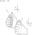
- FIGS. 8 to 10 are diagrams showing an example of the state where a single user uses the game system 1 by holding a set of the left controller 3 and the right controller 4 in the separate state. As shown in FIGS. 11 to 13 , in the separate state, the user can view an image displayed on the stationary monitor 6 while operating the left controller 3 and the right controller 4 by holding the left controller 3 with their left hand and the right controller 4 with their right hand.
- the user holds the left controller 3 with their left hand such that the down direction of the longitudinal direction of the left controller 3 (the down direction (the negative y-axis direction) shown in FIG. 1 ), which is vertically long and approximately plate-shaped, is the vertical direction, also the side surface that is in contact with the main body apparatus 2 when the left controller 3 is attached to the main body apparatus 2 is directed forward, and also the main surface of the left controller 3 (the surface on which the analog stick 32 is provided) is directed to the right. That is, the left controller 3 held with the left hand of the user is in the state where the negative x-axis direction is directed in the forward direction of the user, and the positive z-axis direction is directed to the left.
- the down direction of the longitudinal direction of the left controller 3 the down direction (the negative y-axis direction) shown in FIG. 1
- the side surface that is in contact with the main body apparatus 2 when the left controller 3 is attached to the main body apparatus 2 is directed forward
- the main surface of the left controller 3 (the surface on which the analog
- the user holds the right controller 4 with their right hand such that the down direction of the longitudinal direction of the right controller 4 (the down direction (the negative y-axis direction) shown in FIG. 1 ), which is vertically long and approximately plate-shaped, is the vertical direction, also the side surface that is in contact with the main body apparatus 2 when the right controller 4 is attached to the main body apparatus 2 is directed forward, and also the main surface of the right controller 4 (the surface on which the analog stick 52 is provided) is directed to the left. That is, the right controller 4 held with the right hand of the user is in the state where the positive x-axis direction is directed in the forward direction of the user, and the positive z-axis direction is directed to the right.
- each controller In the state where the left controller 3 is held with the left hand, and the right controller 4 is held with the right hand (hereinafter, such an operation method will occasionally be referred to as a "two-hand-held operation method", and the orientations of the left controller 3 and the right controller 4 held in these directions will occasionally be referred to as “basic orientations"), each controller is moved in up, down, left, right, front, and back directions, rotated, or swung, whereby game play is performed in accordance with the motion or the orientation of the controller.
- the acceleration sensor 104 of the left controller 3 can detect accelerations in the xyz-axis directions as operation inputs, and the angular velocity sensor 105 can detect angular velocities about the xyz-axis directions as operation inputs.
- the acceleration sensor 114 of the right controller 4 can detect accelerations in the xyz-axis directions as operation inputs, and the angular velocity sensor 115 can detect angular velocities about the xyz-axis directions as operation inputs.
- the left controller 3 includes the vibrator 107
- the right controller 4 includes the vibrator 117.
- the CPU 81 of the main body apparatus 2 transmits vibration data to the left controller 3 and/or the right controller 4 in accordance with the situation of an executed game and thereby can vibrate the vibrator 107 and/or the vibrator 117 at an amplitude and a frequency corresponding to the vibration data.
- FIGS. 11 to 13 are diagrams showing examples of a game image displayed in a game played by moving the left controller 3 and the right controller 4.
- a game e.g., a boxing game
- a player object PO and an enemy object EO compete against each other is displayed on the stationary monitor 6.
- the user operating the left controller 3 and the right controller 4 can operate the player object PO by swinging the main body of the left controller 3 and/or the main body of the right controller 4, changing the orientations of the main body of the left controller 3 and/or the main body of the right controller 4, or pressing an operation button (e.g., the first L-button 38 or the first R-button 60).
- an operation button e.g., the first L-button 38 or the first R-button 60.
- the user swings the left controller 3 and thereby can control the action of a first object G1, which represents a left glove (a left fist) of the player object PO.
- the user swings the right controller 4 and thereby can control the action of a second object G2, which represents a right glove (a right fist) of the player object PO.
- the first object G1, which represents the left glove of the player object PO moves toward the place where the enemy object EO is placed.
- the second object G2 which represents the right glove of the player object PO, moves toward the place where the enemy object EO is placed.
- the left controller 3 when the left controller 3 is swung so as to be pushed forward (in the negative x-axis direction of the left controller 3) in the state where neither of the left controller 3 and the right controller 4 moves, the first object G1 of the player object PO moves toward the enemy object EO in accordance with the motion of the left controller 3. Consequently, a game image is displayed such that the player object PO throws a left punch at the enemy object EO.
- the moving direction of the first object G1 starting moving is set by the orientation of the left controller 3 when the left controller 3 is swung so as to be pushed forward.
- the moving direction of the second object G2 starting moving is set by the orientation of the right controller 4 when the right controller 4 is moved so as to be pushed forward.
- the moving direction of the second object G2 is set in accordance with the orientation in a roll direction of the right controller 4 in this movement.
- the tilt in the y-axis direction of the right controller 4 with respect to the direction in which a gravitational acceleration acts in real space is calculated, and the moving direction of the second object G2 is calculated based on the tilt in the y-axis direction.
- the tilt in the y-axis direction indicates that the right controller 4 is in the orientation in which the right controller 4 roll-rotates in the right direction with respect to the above reference orientation
- the second object G2 moves in the right direction in a virtual space.
- the tilt in the y-axis direction indicates that the right controller 4 is in the orientation in which the right controller 4 roll-rotates in the left direction with respect to the reference orientation
- the second object G2 moves in the left direction in the virtual space. Then, the angle at which the moving direction shifts in the right direction or the left direction is calculated in accordance with the tilt angle in the y-axis direction.
- the distance between the player object PO and the enemy object EO is relatively long in the virtual space, it is possible to throw a punch.
- the arms of the player object PO extend, whereby the first object G1 and the second object G2 can move by a relatively long distance.
- the first object G1 or the second object G2 collides with another object (e.g., the enemy object EO) or moves by a predetermined distance, then finishes the movement, and returns to a movement start position where the first object G1 or the second object G2 starts moving (e.g., a hand portion of the player object PO shown in FIG. 11 ).
- the first object G1 and the second object G2 return to the movement start positions and thereby can make a next movement toward the enemy object EO. In other words, it is possible to throw a next punch.
- the time from when the first object G1 or the second object G2 starts moving from the movement start position to when the first object G1 or the second object G2 returns to the movement start position again is longer than in a general boxing game.
- the first object G1 or the second object G2 is moving using such a movement time (typically, the period in which the first object G1 or the second object G2 is moving in the direction of the enemy object EO)
- a trajectory moving in accordance with the orientation or the motion of the left controller 3 or the right controller 4 For example, when the left controller 3 or the right controller 4 rotates in the roll direction or rotates in a yaw direction from the orientation of the left controller 3 or the right controller 4 when the first object G1 or the second object G2 starts moving, the trajectory of the first object G1 or the second object G2 is changed in accordance with the rotation.
- the trajectory of the first object G1 or the second object G2 moving based on this rotational velocity about the x-axis is changed.
- the rotational velocity of the left controller 3 roll-rotating in the right direction about the x-axis while the first object G1 is moving is obtained, the trajectory of the first object G1 is changed in the right direction in the virtual space.
- the trajectory of the first object G1 is changed in the left direction in the virtual space.
- the rotational velocity of the right controller 4 roll-rotating in the right direction about the x-axis while the second object G2 is moving is obtained, the trajectory of the second object G2 is changed in the right direction in the virtual space.
- the rotational velocity of the right controller 4 roll-rotating in the left direction about the x-axis is obtained, the trajectory of the second object G2 is changed in the left direction in the virtual space.
- the trajectory of the first object G1 or the second object G2 moving based on this rotational velocity is changed.
- the rotational velocity of the left controller 3 yaw-rotating in the right direction about the direction of gravity while the first object G1 is moving is obtained, the trajectory of the first object G1 is changed in the right direction in the virtual space.
- the trajectory of the first object G1 is changed in the left direction in the virtual space.
- the rotational velocity of the right controller 4 yaw-rotating in the right direction about the direction of gravity while the second object G2 is moving is obtained, the trajectory of the second object G2 is changed in the right direction in the virtual space.
- the rotational velocity of the right controller 4 yaw-rotating in the left direction about the direction of gravity is obtained, the trajectory of the second object G2 is changed in the left direction in the virtual space.
- the left controller 3 or the right controller 4 uses the magnitude of an acceleration generated in the left controller 3 or the right controller 4, it is determined whether or not the left controller 3 or the right controller 4 is swung. Then, when it is determined that the left controller 3 is swung in the negative x-axis direction in the state where the first object G1 is placed at the movement start position, the first object G1 starts moving from the movement start position toward the enemy object EO. Further, when it is determined that the right controller 4 is swung in the positive x-axis direction in the state where the second object G2 is placed at the movement start position, the second object G2 starts moving from the movement start position toward the enemy object EO.
- the user swings the right controller 4 so as to push the right controller 4 forward (in the positive x-axis direction of the right controller 4), whereby the second object G2 starts moving toward the enemy object EO.
- the user swings the left controller 3 so as to push the left controller 3 forward (in the negative x-axis direction of the left controller 3) during the movement of the second object G2, whereby the first object G1 also starts moving toward the enemy object EO.
- FIG. 16 shows an example of a game image in which the second object G2 having started moving first collides with (hits) the enemy object EO.
- vibrations are imparted to the left controller 3 and/or the right controller 4 in accordance with the states of the first object G1 and/or the second object G2 in a virtual game world.
- a vibration corresponding to the type, the moving velocity, the moving direction, the collision state, and the like of the first object G1 is imparted to the left controller 3.
- a vibration corresponding to the type, the moving velocity, the moving direction, the collision state, and the like of the second object G2 is imparted to the right controller 4.
- the player object PO it is possible to move the player object PO or cause the player object PO to perform an action in the virtual game world in accordance with the motions or the orientations of both the left controller 3 and the right controller 4.
- the player object PO is caused to move in accordance with the tilts of the rotations.
- the tilts in the x-axis direction and the y-axis direction of the left controller 3 and the tilts in the x-axis direction and the y-axis direction of the right controller 4 with respect to the direction of gravity in real space are calculated.
- the player object PO is caused to move forward in the virtual game world by the amount of movement corresponding to the angles at which both the left controller 3 and the right controller 4 are tilted forward (e.g., the average value of these angles).
- the player object PO is caused to move backward in the virtual game world by the amount of movement corresponding to the angles at which both the left controller 3 and the right controller 4 are tilted backward (e.g., the average value of these angles).
- the player object PO is caused to move to the left in the virtual game world by the amount of movement corresponding to the angles at which both the left controller 3 and the right controller 4 are tilted to the left (e.g., the average value of these angles).
- the player object PO when it is determined that both the left controller 3 and the right controller 4 are in the orientations in which the left controller 3 and the right controller 4 are tilted to the right, the player object PO is caused to move to the right in the virtual game world by the amount of movement corresponding to the angles at which both the left controller 3 and the right controller 4 are tilted to the right (e.g., the average value of these angles). Further, based on these tilts, when it is determined that both the left controller 3 and the right controller 4 are in the orientations in which the left controller 3 and the right controller 4 are tilted inward, the player object PO performs the action of defending against an attack from the enemy object EO in the virtual game world.
- the player object PO in accordance with operations on the operation buttons of the left controller 3 and the right controller 4, it is possible to cause the player object PO to move or perform an action in the virtual space. For example, when the first L-button 38 of the left controller 3 is subjected to a pressing operation, the player object PO moves dashing (moves rapidly) in the virtual game world. Further, when the first R-button 60 of the right controller 4 is subjected to a pressing operation, the player object PO jumps in the virtual game world.
- an attachment for attaching the left controller 3 and the right controller 4 to cause the left controller 3 and the right controller 4 to function as a single operation device.
- FIGS. 14 and 15 are diagrams showing an example of an accessory device to which the left controller 3 and the right controller 4 are attachable.
- an extension grip 350 which is an example of the accessory device, is an accessory device used by the user to perform an operation.
- the left controller 3 is attachable to the extension grip 350
- the right controller 4 is also attachable to the extension grip 350.
- the user can perform an operation (hereinafter, such an operation method will occasionally be referred to as an "extension grip operation method") by holding, in a unified manner, the two controllers 3 and 4 detached from the main body apparatus 2.
- the extension grip 350 includes a main body portion 351 and a supporting portion 352.
- the main body portion 351 includes a left grip portion 353, which is held by the user with their left hand, and a right grip portion 354, which is held by the user with their right hand.
- the main body portion 351 can also be said to be a holding portion.
- the main body portion 351 includes a connection portion 355.
- the connection portion 355 connects the left grip portion 353 and the right grip portion 354.
- the connection portion 355 is, for example, a member extending in the horizontal direction (i.e., an x-axis direction shown in FIGS. 14 and 15 ).
- the left grip portion 353 is provided in a left end portion of the connection portion 355, and the right grip portion 354 is provided in a right end portion of the connection portion 355.
- the left grip portion 353 is shaped to extend in the up-down direction (i.e., a y-axis direction shown in FIGS. 14 and 15 ).
- the right grip portion 354 is also shaped to extend in the up-down direction.
- the left grip portion 353 and the right grip portion 354 are shaped to extend in directions slightly obliquely inclined with respect to the up-down direction. Specifically, the left grip portion 353 and the right grip portion 354 are inclined in such directions that the further downward from portions in which the left grip portion 353 and the right grip portion 354 are connected the connection portion 355, the further away the left grip portion 353 and the right grip portion 354 are from each other.
- the grip portions 353 and 354 have such shapes, whereby the user can comfortably hold the grip portions 353 and 354 and comfortably operate the controllers 3 and 4 attached to the extension grip 350.
- the main body portion 351 is formed of a single housing (in other words, a housing formed in a unified manner).
- the housing of the main body portion 351 is composed of a resin.
- the main body portion 351 may have a configuration in which a plurality of housings (e.g., housings for the respective components 353 to 355) are connected together.
- the supporting portion 352 is a member for supporting the controllers 3 and 4. As shown in FIGS. 14 and 15 , the supporting portion 352 is joined to the main body portion 351 (specifically, the connection portion 355 of the main body portion 351).
- the supporting portion 352 (in other words, a housing of the supporting portion 352) has an approximately cuboid outer shape, and a back surface (i.e., a surface further in the positive z-axis direction) of the supporting portion 352 is joined to a front surface (i.e., the surface further in the negative z-axis direction) of the connection portion 355.
- the housing of the supporting portion 352 is composed of a resin.
- the main body portion 351 and the supporting portion 352 may be formed in a unified manner, and the main body portion 351 and the supporting portion 352 may be formed of a single housing.
- the left controller 3 and the right controller 4 can be simultaneously attached.
- the extension grip 350 includes a mechanism similar to the mechanism of the main body apparatus 2 for attaching the left controller 3 to its left side surface.
- the extension grip 350 includes a mechanism similar to the mechanism of the main body apparatus 2 for attaching the right controller 4 to its right side surface. Then, as shown in FIG.
- the left controller 3 and the right controller 4 are attached to the extension grip 350, the left controller 3 is on the left side of the right controller 4, and the left controller 3 and the right controller 4 are supported by the extension grip 350 such that the left controller 3 and the right controller 4 are in the same direction (i.e., the positive y-axis directions of the left controller 3 and the right controller 4 are substantially parallel and are the same direction).
- the left grip portion 353 is placed on the left side of the left controller 3 attached to the extension grip 350
- the right grip portion 354 is placed on the right side of the right controller 4 attached to the extension grip 350. This enables the user to hold the extension grip 350 and the left controller 3 and the right controller 4 attached to the extension grip 350 as if a single controller. Further, the user can hold the left controller 3 and the right controller 4 with the feeling that the user holds the left grip portion 353 and the right grip portion 354 directly connected to the outside of the left controller 3 and the right controller 4.
- the left controller 3 and the right controller 4 can be attached in the state where the extension grip 350 is not electrically connected to the left controller 3 and the right controller 4.
- user notification LEDs may be provided on an attachment surface (a right side surface further in the negative x-axis direction) of the left controller 3 or an attachment surface (a left side surface further in the positive x-axis direction) of the right controller 4.
- the extension grip 350 has a configuration for enabling the user to view light from the notification LEDs in the state where the extension grip 350 is not electrically connected to the left controller 3 and the right controller 4.
- incident surfaces of light guide paths 358 for guiding light from notification LEDs are provided corresponding to the placement positions of the notification LEDs.
- exit surfaces of the light guide paths 358 are provided on an outer surface of the supporting portion 352 (e.g., a front surface of the supporting portion 352 (i.e., a surface further in the negative z-axis direction).
- the moving directions of the first object G1 and/or the second object G2 that are moving change in accordance with the direction of the tilt operation and the tilt angle.
- the analog stick 32 of the left controller 3 is subjected to a tilt operation in a case where both the first object G1 and the second object G2 are placed at the movement start positions, the player object PO moves in the virtual game world in accordance with the direction of the tilt operation and the tilt angle.
- the player object PO defends against an attack from the enemy object EO in the virtual game world.
- the player object PO performs the action of jumping in the virtual game world.
- the Y-button 56 of the right controller 4 is subjected to a pressing operation, the player object PO dashes (moves rapidly) in the virtual game world.
- vibrations are imparted to the left controller 3 and/or the right controller 4 attached to the extension grip 350 in accordance with the states of the first object G1 and/or the second object G2 in the virtual game world.
- FIG. 17 is an example of an operation correspondence table indicating the actions of the player object PO for operation contents in each of the above operation methods (the two-hand-held operation method and the extension grip operation method).
- a setting may be made so that even when the same operation is performed using the left controller 3 and/or the right controller 4, the corresponding game processing may be different due to the fact that the operation method is different.
- a predetermined object image e.g., a cursor image
- a direction indicated by the longitudinal direction (the positive y-axis direction) of the left controller 3 is calculated, and an object image is displayed such that a position on a display screen corresponding to the calculated direction is a pointing position.
- the pointing position is moved in accordance with angular velocities generated by this change.
- the extension grip operation method when an indicating operation is performed using the left controller 3 and the right controller 4 attached to the extension grip 350, then similarly, in accordance with an indicated position, a predetermined object image (e.g., a cursor image) is displayed on the stationary monitor 6.
- a predetermined object image e.g., a cursor image
- the amount of movement of the pointing position in accordance with a change in an indicated direction is relatively large.
- the extension grip operation method when the direction of the longitudinal direction of the left controller 3 (or the right controller 4) changes, the amount of movement of the pointing position in accordance with angular velocities generated by this change is a magnitude obtained by multiplying the amount of movement in the two-hand-held operation method by a coefficient equal to or greater than 1.
- the extension grip operation method even when the same operation for changing an indicated direction is performed at the same angular velocities as those in the two-hand-held operation method, a correction process for making the distance at which the pointing position moves relatively great is performed.
- the correction process can perform an appropriate process corresponding to the level of difficulty of the operation.
- the extension grip 350 is not electrically connected to the left controller 3 and the right controller 4.
- an operation method e.g., the two-hand-held operation method or the extension grip operation method used by the user is determined based on the motions and/or the orientations of the left controller 3 and the right controller 4.
- the operation method is determined by the main body apparatus 2, using data based on the motion and/or the orientation of the left controller 3 detected by a motion/orientation sensor included in the left controller 3 (e.g., the acceleration sensor 104 or the angular velocity sensor 105), and data based on the motion and/or the orientation of the right controller 4 detected by a motion/orientation sensor included in the right controller 4 (e.g., the acceleration sensor 114 or the angular velocity sensor 115).
- a motion/orientation sensor included in the left controller 3 e.g., the acceleration sensor 104 or the angular velocity sensor 105
- data based on the motion and/or the orientation of the right controller 4 detected by a motion/orientation sensor included in the right controller 4 e.g., the acceleration sensor 114 or the angular velocity sensor 115.
- the main body apparatus 2 makes the determination based on whether or not a first condition that the difference between the orientations of the left controller 3 and the right controller 4 is within a predetermined range and a second condition that the difference between the amounts of change in the orientations of the left controller 3 and the right controller 4 is within a predetermined range are satisfied. Then, when the determinations are affirmative in both the first condition and the second condition, it is determined that the user is performing an operation using the extension grip operation method. When the determination is negative in at least one of the first condition and the second condition, it is determined that the user is performing an operation using the two-hand-held operation method.
- the determination based on the first condition is made as follows.
- orientations in the left-right directions in real space which are directions about the directions of the gravitational accelerations, may be corrected so that to the orientation of one of the controllers, the orientation of the other controller is always adjusted.
- the degree of coincidence between the orientations is determined. Then, when the state where the difference between the orientations of the left controller 3 and the right controller 4 is within the predetermined range continues for a predetermined time, the determination based on the first condition is affirmative. When the difference between the orientations of the left controller 3 and the right controller 4 goes outside the predetermined range, the determination based on the first condition is immediately negative.
- the determination based on the second condition is made as follows. Angular velocities about axes (e.g., the xyz axes) acting on the left controller 3 and the right controller 4 are accumulated to calculate the directions of the respective axes. When the difference between the amounts of change in the axial directions is within a predetermined range, the determination is affirmative.
- the amounts of change in the axial directions conceptually represent the angular velocities about the axes.
- the determination based on the second condition can also be considered as a determination in which, when the difference between the angular velocities is within a predetermined range, the determination is affirmative.
- the second condition is determined using the difference between the amounts of change in the longitudinal directions (the y-axis directions) and the difference between the amounts of change in the left-right directions (the x-axis directions) in the xyz axes defined in the left controller 3 and the right controller 4. Then, when the state where the difference between the amounts of change in the axial directions of the left controller 3 and the right controller 4 is within the predetermined range continues for a predetermined time, the determination based on the second condition is affirmative. When the state where the difference between the amounts of change in the axial directions of the left controller 3 and the right controller 4 is outside the predetermined range continues for a predetermined time, the determination based on the second condition is negative.
- an operation using the two-hand-held operation method or the extension grip operation method is determined depending on a case where both the first condition and the second condition are satisfied, and a case where at least one of the first condition and the second condition is satisfied.
- the operation method is determined thus using two conditions, whereby it is possible to accurately determine various operations. For example, when one of the controllers is moved to rotate about the gravitational acceleration, both controllers may enter the state where the orientations of the controllers coincide with each other, and the determination based on the first condition may be affirmative. However, the determination based on the second condition is always negative.
- the determination based on the second condition is also made, whereby it is possible to accurately determine that the operation method is the two-hand-held operation method even in the above state. Further, even when an operation is performed using the two-hand-held operation method, and in the state where both controllers make the same motion, the determination based on the second condition may be affirmative. However, if the orientations of the controllers do not coincide with each other, the determination based on the first condition is always negative. That is, in the determination using only the second condition, it may be erroneously determined that the operation method is an operation using the extension grip operation method.
- the determination based on the first condition is also made, whereby it is possible to accurately determine that the operation method is the two-hand-held operation method even in the above state. If such effects are not desired, the operation method used by the user may be determined using one of the first condition and the second condition. Further, the operation method used by the user may be determined by adding another condition described later to the first condition and the second condition.
- the main body apparatus 2 makes the determination based on whether or not a third condition that the difference between the value of data based on the detection result of the motion/orientation sensor included in the left controller 3 (e.g., the value of angular velocity data detected by the angular velocity sensor 105) and the value of data based on the detection result of the motion/orientation sensor included in the right controller 4 (e.g., the value of angular velocity data detected by the angular velocity sensor 115) is within a predetermined range is satisfied. Then, when the determination using the third condition is affirmative, it is determined that the user is performing an operation using the extension grip operation method.
- a third condition that the difference between the value of data based on the detection result of the motion/orientation sensor included in the left controller 3 (e.g., the value of angular velocity data detected by the angular velocity sensor 105) and the value of data based on the detection result of the motion/orientation sensor included in the right controller 4 (e.g., the value of angular velocity data
- the determination using the third condition is negative, it is determined that the user is performing an operation using the two-hand-held operation method. Then, when the state where the difference between the values of the above data output from the left controller 3 and the right controller 4 is within the predetermined range continues for a predetermined time, the determination based on the third condition is affirmative. When the state where the difference between the values of the above data output from the left controller 3 and the right controller 4 is outside the predetermined range continues for a predetermined time, the determination based on the third condition is negative.
- the first example and the second example of the determination of the operation method are mere examples of the determination of the operation method based on the motions and/or the orientations of the left controller 3 and the right controller 4.
- the operation method may be determined using another parameter.
- the process of determining the operation method may be performed only in a case where the left controller 3 and the right controller 4 are moving (i.e., by eliminating a case where the left controller 3 and the right controller 4 remain still). In this case, in the state where the left controller 3 and the right controller 4 are moving, and when the difference between the values of angular velocities generated in the controllers is within a predetermined range, it is possible to determine that the user is performing an operation using the extension grip operation method.
- the process of determining the operation method may be performed using the values of accelerations generated in the left controller 3 and the right controller 4.
- the process of determining the operation method may be performed using the values of accelerations generated in the left controller 3 and the right controller 4.
- the directions of the gravitational accelerations generated in the left controller 3 and the right controller 4, or the directions of accelerations generated in accordance with the motions of the left controller 3 and/or the right controller 4 when the left controller 3 and the right controller 4 are in the same orientation and/or are making the same motion, it is possible to determine that the user is performing an operation using the extension grip operation method.
- the left controller 3 and the right controller 4 are in different orientations and/or are making different motions, it is possible to determine that the user is performing an operation using the two-hand-held operation method.
- the process of determining the operation method may be performed based on data based on the motion and/or the orientation of the left controller 3 detected by another motion/orientation sensor for detecting at least one of the motion and the orientation of the left controller 3, and data based on the motion and/or the orientation of the right controller 4 detected by another motion/orientation sensor for detecting at least one of the motion and the orientation of the right controller 4.
- another motion/orientation sensor it is possible to use a magnetic sensor for detecting the direction of magnetism generated in the controller, an image capturing apparatus for capturing a predetermined direction from the controller, or the like.
- the process of determining the operation method when the left controller 3 and/or the right controller 4 are making predetermined motions or are in predetermined orientations, the determination may not be made, and the result of the determination of the operation method in the past set at this time may be maintained.
- the process of changing the operation method from the two-hand-held operation method to the extension grip operation method e.g., the process of determining the operation method
- the process of determining the operation method may not be performed.
- the process of changing the operation method from the extension grip operation method to the two-hand-held operation method may not be performed.
- the operation of swinging and moving the left controller 3 and/or the right controller 4 is frequently used in an operation using the two-hand-held operation method.
- accelerations exceeding a threshold are generated in the left controller 3 and/or the right controller 4, the process of determining the operation method may not be performed.
- the operation of setting the longitudinal directions of the left controller 3 and/or the right controller 4 to the vertical direction i.e., the operation in which the negative y-axis directions are directed in the vertical direction
- the process of determining the operation method may not be performed.
- FIG. 18 is a diagram showing an example of a data area set in the DRAM 85 of the main body apparatus 2 according to the exemplary embodiment. It should be noted that in the DRAM 85, in addition to data shown in FIG. 18 , data used for other processes is also stored, but is not described in detail here.
- various programs Pa which are executed by the game system 1, are stored.
- a communication program for wirelessly communicating with the left controller 3 and the right controller 4 an application program for performing information processing (e.g., game processing) based on data acquired from the left controller 3 and/or the right controller 4, a determination program for determining an operation method using the left controller 3 and/or the right controller 4, and the like are stored.
- the various programs Pa may be stored in advance in the flash memory 84, or may be acquired from a storage medium attachable to and detachable from the game system 1 (e.g., the predetermined type of storage medium attached to the slot 23) and stored in the DRAM 85, or may be acquired from another apparatus via a network such as the Internet and stored in the DRAM 85.
- the CPU 81 executes the various programs Pa stored in the DRAM 85.
- a data storage area of the DRAM 85 various data used for processes such as a communication process, information processing, and the like executed by the game system 1 is stored.
- operation data Da angular velocity data Db, acceleration data Dc, axial direction data Dd, orientation data De, operation method flag data Df, determination-allowed flag data Dg, operation correspondence table data Dh, player object position data Di, enemy object position data Dj, image data Dk, and the like are stored.
- the operation data Da is operation data appropriately acquired from each of the left controller 3 and/or the right controller 4.
- operation data transmitted from each of the left controller 3 and/or the right controller 4 includes information regarding an input (specifically, information regarding an operation or the detection result of each sensor) from each input section (specifically, each button, an analog stick, and each sensor).
- operation data is transmitted from each of the left controller 3 and/or the right controller 4 in a predetermined cycle through wireless communication, and the operation data Da is appropriately updated using the received operation data.
- the update cycle of the operation data De may be such that the operation data Da is updated every frame, which is the cycle of the processing described later performed by the game system 1, or is updated every cycle in which operation data is transmitted through the above wireless communication.
- the angular velocity data Db is data indicating angular velocities generated in each of the left controller 3 and the right controller 4.
- the angular velocity data Db includes data indicating angular velocities about the xyz axes generated in each of the left controller 3 and the right controller 4 and the like.
- the acceleration data Dc is data indicating accelerations generated in each of the left controller 3 and the right controller 4.
- the acceleration data De includes data indicating accelerations generated in the xyz-axis directions except for the gravitational acceleration generated in each of the left controller 3 and the right controller 4 and the like.
- the axial direction data Dd is data indicating the axial directions of each of the left controller 3 and the right controller 4.
- the axial direction data Dd includes data indicating the xyz-axis directions obtained by accumulating angular velocities about the xyz axes of each of the left controller 3 and the right controller 4 and the like.
- the orientation data De is data indicating each of the orientations of the left controller 3 and the right controller 4 with respect to the direction of a gravitational acceleration in real space.
- the orientation data De includes data indicating the direction of a gravitational acceleration acting on each of the left controller 3 and the right controller 4, data indicating xyz-axis directions relative to the direction of the gravitational acceleration, and the like.
- the operation method flag data Df is data indicating an operation method flag indicating an operation method (e.g., the two-hand-held operation method or the extension grip operation method) determined and set, and is set to on when the extension grip operation method is set.
- the determination-allowed flag data Dg is data indicating a determination-allowed flag, which is set to on when the process of determining the operation method can be performed.
- the operation correspondence table data Dh is data indicating the operation correspondence table (see FIG. 17 ) in which the contents of instructions to be given corresponding to operations are described with respect to each operation method.
- the player object position data Di is data indicating each of the positions and the directions (the moving directions) in the virtual space of the first object G1, the second object G2, and the player object PO.
- the enemy object position data Dj is data indicating the position and the direction in the virtual space of the enemy object EO and data indicating the positions and the directions in the virtual space of objects shot from the enemy object EO (e.g., objects representing the left glove (the left fist) and the right glove (the right fist)).
- the image data Dk is data for displaying an image (e.g., an image of a virtual object, a field image, or a background image) on the display 12 of the main body apparatus 2 or the display screen of the stationary monitor 6 when a game is performed.
- an image e.g., an image of a virtual object, a field image, or a background image
- FIG. 19 is a flow chart showing an example of game processing executed by the game system 1.
- FIG. 20 is a subroutine showing an example of the details of an operation method determination process performed in step S143 in FIG. 19 .
- FIG. 21 is a subroutine showing an example of the details of a capability determination process performed in step S162 in FIG. 20 .
- FIG. 22 is a subroutine showing an example of the details of a two-hand-held game process performed in step S146 in FIG. 19 .
- FIG. 23 is a subroutine showing an example of the details of an extension grip game process performed in step S147 in FIG. 19 .
- a series of processes shown in FIGS. 19 to 23 is performed by the CPU 81 executing the communication program and a predetermined application program (a game program) included in the various programs Pa. Further, the game processing shown in FIGS. 19 to 23 is started at any timing.
- part of the processing performed by the main body apparatus 2 may be executed by another information processing apparatus capable of communicating with the main body apparatus 2 (e.g., a server capable of communicating with the main body apparatus 2 via a network). That is, all the processes shown in FIGS. 19 to 23 may be executed by the cooperation of a plurality of information processing apparatuses including the main body apparatus 2.
- the CPU 81 performs initialization in the game processing (step S141), and the processing proceeds to the next step.
- the CPU 81 initializes parameters for performing the processing described below.
- the CPU 81 sets a game field for performing game play and sets the initial positions of the player object PO and the enemy object EO on the game field, thereby updating the player object position data Di and the enemy object position data Dj.
- the CPU 81 initializes the moving directions of the first object G1 and the second object G2 to default values (e.g., front directions), thereby updating the player object position data Di.
- the CPU 81 acquires operation data from the left controller 3 and/or the right controller 4 and updates the operation data Da (step S142), and the processing proceeds to the next step.
- step S143 the CPU 81 performs an operation method determination process (step S143), and the processing proceeds to the next step.
- the operation method determination process is described below.
- the CPU 81 calculates the accelerations, the angular velocities, and the orientation of each of the left controller 3 and the right controller 4 (step S161), and the processing proceeds to the next step.
- the CPU 81 acquires data indicating accelerations generated in each of the left controller 3 and the right controller 4 from the operation data Da, removes a gravitational acceleration component from accelerations about the xyz-axis directions generated in each of the left controller 3 and the right controller 4, and updates the acceleration data De using data indicating the accelerations after the removal.
- a method for extracting a gravitational acceleration any method may be used.
- an acceleration component generated on average in each of the left controller 3 and the right controller 4 may be calculated and extracted as a gravitational acceleration.
- the CPU 81 accumulates angular velocities generated in each of the left controller 3 and the right controller 4, thereby calculating the axial directions of each of the left controller 3 and the right controller 4. Then, the CPU 81 updates the axial direction data Dd using data indicating the axial directions.
- the CPU 81 acquires, from the operation data Da, data indicating angular velocities generated in each of the left controller 3 and the right controller 4, calculates angular velocities about the xyz axes of each of the left controller 3 and the right controller 4, and accumulates the angular velocities, thereby calculating the xyz-axis directions of each of the left controller 3 and the right controller 4. It should be noted that as will be apparent later, the CPU 81 also maintains axial direction data calculated in the previous process to calculate the amounts of change in the xyz-axis directions.
- the CPU 81 calculates, as the orientation of the left controller 3, the xyz-axis directions of the left controller 3 with respect to the direction of the gravitational acceleration calculated for the left controller 3 and updates the orientation data De using data indicating the orientation. Further, the CPU 81 calculates, as the orientation of the right controller 4, the xyz-axis directions of the right controller 4 with respect to the direction of the gravitational acceleration calculated for the right controller 4 and updates the orientation data De using data indicating the orientation.
- the CPU 81 corrects the above orientation so that predetermined axial directions (e.g., the positive x-axis directions) of the left controller 3 and the right controller 4 about the direction of the gravitational acceleration coincide with each other, thereby updating the orientation data De. Specifically, the CPU 81 calculates horizontal direction components of the positive x-axis directions of the left controller 3 and the right controller 4 and corrects one of the orientations of the left controller 3 and the right controller 4 by rotating the orientation about the direction of the gravitational acceleration so that the directions of the horizontal direction components coincide with each other.
- predetermined axial directions e.g., the positive x-axis directions
- the CPU 81 calculates horizontal direction components of the positive x-axis directions of the left controller 3 and the right controller 4 and corrects one of the orientations of the left controller 3 and the right controller 4 by rotating the orientation about the direction of the gravitational acceleration so that the directions of the horizontal direction components coincide with each other.
- the orientation of the left controller 3 or the right controller 4 may be updated in accordance with only the angular velocities about the xyz axes.
- the xyz-axis directions relative to the direction of the gravitational acceleration may be calculated and the above correction is made every predetermined cycle, and the orientation of the left controller 3 or the right controller 4 may be corrected.
- step S162 the CPU 81 performs a capability determination process (step S162), and the processing proceeds to the next step.
- the capability determination process is described below.
- the CPU 81 determines whether or not the orientations are an elimination orientation for eliminating the performance of the operation method determination process (step S181). For example, with reference to the orientation data De, the CPU 81 acquires the orientations of the left controller 3 and the right controller 4 and determines whether or not the orientations are included in the elimination orientation. Specifically, when the orientations in which the longitudinal directions of the left controller 3 and/or the right controller 4 are the vertical direction (i.e., the orientation in which the negative y-axis directions are directed in the vertical direction) are set to the elimination orientation, the CPU 81 performs the determination process in the above step S181 based on whether or not the negative y-axis directions indicated by the orientation data De are included in a range recognized as the elimination orientation. Then, when the orientations are not the elimination orientation, the processing proceeds to step S182. On the other hand, when the orientations are the elimination orientation, the processing proceeds to step S187.
- step S182 the CPU 81 determines whether or not an acceleration generated in the left controller 3 or the right controller 4 is equal to or greater than a predetermined value. For example, with reference to the acceleration data De, the CPU 81 acquires the magnitudes of accelerations generated in the left controller 3 and the right controller 4. When at least one of the magnitudes of the accelerations is greater than the predetermined value, the determination is affirmative in the above step S182.
- the predetermined value is set to a threshold that, when the user moves the left controller 3 and/or the right controller 4, allows the determination of the accelerations generated in the left controller 3 and/or the right controller 4. Then, when both the accelerations generated in the left controller 3 and the right controller 4 are less than the predetermined value, the processing proceeds to step S183. On the other hand, when at least one of the accelerations generated in the left controller 3 and the right controller 4 is equal to or greater than the predetermined value, the processing proceeds to step S187.
- step S183 the CPU 81 determines whether or not the determination-allowed flag is set to off. For example, with reference to the determination-allowed flag data Dg, the CPU 81 determines whether or not the determination-allowed flag is set to off. Then, when the determination-allowed flag is set to off, the processing proceeds to step S184. On the other hand, when the determination-allowed flag is set to on, the processing of this subroutine ends.
- step S184 the CPU 81 adds 1 to a temporary variable T3, and the processing proceeds to the next step.
- the temporary variable T3 is a parameter indicating a stability time of the left controller 3 and the right controller 4 for performing the operation method determination process. Every time the above step S184 is executed, 1 is added to the temporary variable T3, thereby measuring the stability time.
- the CPU 81 determines whether or not the temporary variable T3 reaches a threshold A3 (step S185).
- step S186 the CPU 81 sets the determination-allowed flag to on, and the processing of this subroutine ends. For example, the CPU 81 sets the determination-allowed flag to on, thereby updating the determination-allowed flag data Dg.
- the CPU 81 sets the determination-allowed flag to on so that the operation method determination process can be executed.
- the CPU 81 initializes all temporary variables T1, T2, and T3 to 0 (step S187), and the processing proceeds to the next step.
- the temporary variable T1 is a parameter indicating the time in which the difference between the amounts of change in the axial directions is within a predetermined range.
- the temporary variable T2 is a parameter indicating the time in which the difference between the amounts of change is outside the predetermined range.
- the CPU 81 sets the determination-allowed flag to off, and the processing of this subroutine ends. For example, the CPU 81 sets the determination-allowed flag to off, thereby updating the determination-allowed flag data Dg.
- the CPU 81 sets the determination-allowed flag to off so that the operation method determination process cannot be executed.
- step S163 the CPU 81 determines whether or not the determination-allowed flag is set to on. Then, when the determination-allowed flag is set to on, the processing proceeds to step S164. On the other hand, when the determination-allowed flag is set to off, the processing of this subroutine ends without the CPU 81 performing an operation method determination process described later.
- step S164 the CPU 81 determines whether or not the orientation of the left controller 3 and the orientation of the right controller 4 coincide with each other. Then, when the orientation of the left controller 3 and the orientation of the right controller 4 coincide with each other, the processing proceeds to step S165. On the other hand, when the orientation of the left controller 3 and the orientation of the right controller 4 do not coincide with each other, the processing proceeds to step S172. For example, with reference to the orientation data De, the CPU 81 acquires the orientations of the left controller 3 and the right controller 4. When the difference between the orientations is within a predetermined range, the determination is affirmative in the above step S164.
- the predetermined range is an allowable amount of shift of each axial direction based on which it is determined that the orientation of the left controller 3 and the orientation of the right controller 4 coincide with each other in real space.
- the degree of coincidence between two axes e.g., the x-axis and the y-axis
- the determination is affirmative in the above step S164.
- step S165 the CPU 81 determines whether or not the amounts of change in the axial directions coincide with each other. Then, when the amounts of change in the axial directions coincide with each other, the processing proceeds to step S166. On the other hand, when the amounts of change in the axial directions do not coincide with each other, the processing proceeds to step S173. For example, with reference to the axial direction data Dd, when the difference between the amount of change in the axial direction of the left controller 3 and the amount of change in the axial direction of the right controller 4 is within a predetermined range, the determination is affirmative in the above step S165.
- CPU 81 compares the angular difference (the amount of change) between the positive x-axis direction of the left controller 3 set in the previous process and the positive x-axis direction of the left controller 3 set in the current process, with the angular difference (the amount of change) between the positive x-axis direction of the right controller 4 set in the previous process and the positive x-axis direction of the right controller 4 set in the current process.
- the difference between the angular differences is within a predetermined range, it is determined that the amounts of change in the x-axis directions coincide with each other.
- the CPU 81 compares the angular difference (the amount of change) between the positive y-axis direction of the left controller 3 set in the previous process and the positive y-axis direction of the left controller 3 set in the current process, with the angular difference (the amount of change) between the positive y-axis direction of the right controller 4 set in the previous process and the positive y-axis direction of the right controller 4 set in the current process.
- the difference between the angular differences is within a predetermined range, it is determined that the amounts of change in the y-axis directions coincide with each other.
- the determination is affirmative in the above step S165.
- step S166 the CPU 81 initializes the temporary variable T2 to 0, and the processing proceeds to the next step.
- step S167 the CPU 81 determines whether or not the operation method flag is set to off. For example, with reference to the operation method flag data Df, the CPU 81 determines whether or not the operation method flag is set to off. Then, when the operation method flag is set to off, the processing proceeds to step S168. On the other hand, when the operation method flag is set to on, the processing of this subroutine ends.
- step S168 the CPU 81 adds 1 to the temporary variable T1, and the processing proceeds to the next step.
- the temporary variable T1 is a parameter indicating the time in which the difference between the amounts of change in the axial directions is maintained within the predetermined range. Every time the above step S168 is executed, 1 is added to the temporary variable T1, thereby measuring the time.
- the CPU 81 determines whether or not the temporary variable T1 reaches the threshold A1 (step S169).
- step S170 the CPU 81 determines whether or not a predetermined input is provided. Then, when the predetermined input is provided, the processing proceeds to step S171. On the other hand, when the predetermined input is not provided, the processing of this subroutine ends. For example, with reference to the operation data Da, when the user performs any of operation inputs used in an operation method set when the operation method flag is set to on, i.e., in the extension grip operation method, the CPU 81 determines that the predetermined input is provided.
- the CPU 81 determines that the predetermined input is provided.
- step S171 the CPU 81 sets the operation method flag to on, and the processing of this subroutine ends. For example, the CPU 81 sets the operation method flag to on, thereby updating the operation method flag data Df.
- the time the temporary variable T1 in which the orientations of the left controller 3 and the right controller 4 coincide with each other (the determination is affirmative in step S164), and the amounts of change in the axial directions coincide with each other (the determination is affirmative in step S165) continues for the predetermined time (the threshold A1) (the determination is affirmative in step S169), the CPU 81 switches the operation method to the extension grip operation method using the provision of the predetermined input as a trigger (sets the operation method flag to on in step S171).
- step S164 when it is determined in the above step S164 that the orientations of the left controller 3 and the orientation of the right controller 4 do not coincide with each other, the CPU 81 initializes the temporary variables T1 and T2 to 0 (step S172), and the processing proceeds to step S177.
- step S165 when it is determined in the above step S165 that the amounts of change in the axial directions do not coincide with each other, the CPU 81 initializes the temporary variable T1 to 0 (step S173), and the processing proceeds to the next step.
- the CPU 81 determines whether or not the operation method flag is set to on (step S174). For example, with reference to the operation method flag data Df, the CPU 81 determines whether or not the operation method flag is set to on. Then, when the operation method flag is set to on, the processing proceeds to step S175. On the other hand, when the operation method flag is set to off, the processing of this subroutine ends.
- step S175 the CPU 81 adds 1 to the temporary variable T2, and the processing proceeds to the next step.
- the temporary variable T2 is a parameter indicating the time in which the state where the difference between the amounts of change in the axial directions exceeds the predetermined range continues. Every time the above step S174 is executed, 1 is added to the temporary variable T2, thereby measuring the time.
- the CPU 81 determines whether or not the temporary variable T2 reaches the threshold A2 (step S176).
- step S177 the CPU 81 sets the operation method flag to off, and the processing of this subroutine ends. For example, the CPU 81 sets the operation method flag to off, thereby updating the operation method flag data Df. As described above, when the orientations of the left controller 3 and the right controller 4 do not coincide with each other (the determination is negative in step S164), the CPU 81 immediately switches the operation method to the two-hand-held operation method (sets the operation method flag to off in step S177).
- the CPU 81 switches the operation method to the two-hand-held operation method (sets the operation method flag to off in step S177).
- the CPU 81 sets the operation method (step S144), and the processing proceeds to the next step.
- the CPU 81 sets an operation mode for use in the game processing.
- the operation mode for use in the game processing is set, whereby the CPU 81 makes a setting so that an operation method corresponding to the operation mode is selected and used based on the description content of the operation correspondence table data Dh in the subsequent game processing.
- step S145 determines whether or not the two-hand-held operation method is selected. Then, when the two-hand-held operation method is selected, the processing proceeds to step S146. On the other hand, when the extension grip operation method is selected, the processing proceeds to step S147.
- step S146 the CPU 81 performs the game processing in a two-hand-held operation mode, and the processing proceeds to step S148.
- step S148 the processing proceeds to step S148.
- FIG. 22 a description is given below of the game processing in the two-hand-held operation mode.
- the CPU 81 performs a left controller swing recognition process (step S193), and the processing proceeds to the next step.
- the CPU 81 determines that the left controller 3 is swung.
- the xy accelerations are accelerations obtained by removing a z-axis direction component (i.e., a horizontal direction component of the left controller 3 in an operation by the two-hand-held operation method described with reference to FIGS. 8 to 13 ) from accelerations generated in the left controller 3.
- the CPU 81 performs a right controller swing recognition process (step S194), and the processing proceeds to the next step.
- the acceleration data De when the magnitudes of xy accelerations generated in the right controller 4 at the current moment are greater than a threshold for a swing determination regarding the right controller 4, the CPU 81 determines that the right controller 4 is swung.
- the xy accelerations are accelerations obtained by removing a z-axis direction component (i.e., a horizontal direction component of the right controller 4 in an operation by the two-hand-held operation method described with reference to FIGS. 8 to 13 ) from accelerations generated in the right controller 4.
- the CPU 81 performs a first object action process (step S195), and the processing proceeds to the next step. For example, in accordance with the determination in the above step S163 that the left controller 3 is swung, the CPU 81 starts the movement of the first object G1 from the movement start position. Then, in accordance with the tilt in the z-axis direction of the left controller 3 relative to the direction of the gravitational acceleration, the CPU 81 changes the moving direction of the first object G1. Specifically, the CPU 81 acquires the orientation of the left controller 3 with reference to the orientation data De and calculates the tilt in the z-axis direction of the left controller 3 relative to the direction of the gravitational acceleration.
- the CPU 81 changes the moving direction of the first object G1. Specifically, with reference to the angular velocity data Db, the CPU 81 acquires angular velocities about the xyz axes generated in the left controller 3, and based on the acquired angular velocities, the CPU 81 calculates the angular velocity of the left controller 3 about the direction of the gravitational acceleration. Then, based on the moving direction and the movement algorithm of the first object G1, the CPU 81 continues the movement of the first object G1 until the first object G1 returns to the movement start position.
- the CPU 81 acquires the position and the moving direction of the first object G1, and based on the moving direction and the movement algorithm, the CPU 81 causes the first object G1 to move from the acquired position of the first object G1. Then, the CPU 81 updates the player object position data Di using the position of the first object G1 after the movement. It should be noted that when the first object G1 is moving on a homeward path in the virtual space for returning to the movement start position, the CPU 81 may fixedly set the moving direction to the direction in which the first object G1 returns from the current position of the first object G1 to the movement start position.
- the position of the first object G1 is set to a position corresponding to this collision state. Further, when the player object PO does not perform the action of throwing a left punch, the position of the first object G1 is set to a movement start position based on the position of the player object PO.
- step S196 the CPU 81 performs a second object action process (step S196), and the processing proceeds to the next step.
- the CPU 81 starts the movement of the second object G2 from the movement start position.
- the CPU 81 changes the moving direction of the second object G2.
- the CPU 81 acquires the orientation of the right controller 4 with reference to the orientation data De and calculates the tilt in the z-axis direction of the right controller 4 relative to the direction of the gravitational acceleration.
- the CPU 81 changes the moving direction of the second object G2. Specifically, with reference to the angular velocity data Db, the CPU 81 acquires angular velocities about the xyz axes generated in the right controller 4, and based on the angular velocities, the CPU 81 calculates the angular velocity of the right controller 4 about the direction of the gravitational acceleration. Then, based on the moving direction and the movement algorithm of the second object G2, the CPU 81 continues the movement of the second object G2 until the second object G2 returns to the movement start position.
- the CPU 81 acquires the position and the moving direction of the second object G2, and based on the moving direction and the movement algorithm, the CPU 81 causes the second object G2 to move from the acquired position of the second object G2. Then, the CPU 81 updates the player object position data Di using the position of the second object G2 after the movement. It should be noted that when the second object G2 is moving on a homeward path in the virtual space for returning to the movement start position, the CPU 81 may fixedly set the moving direction to the direction in which the second object G2 returns from the current position of the second object G2 to the movement start position.
- the position of the second object G2 is set to a position corresponding to this collision state. Further, when the player object PO does not perform the action of throwing a right punch, the position of the second object G2 is set to a movement start position based on the position of the player object PO.
- the CPU 81 performs a player object action process (step S197), and the processing of this subroutine ends. For example, based on a description content corresponding to the two-hand-held operation mode in the operation correspondence table indicated by the operation correspondence table data Dh, the CPU 81 sets the content of an instruction indicated by the operation data acquired in the above step S142, and in accordance with the set content of the instruction, the CPU 81 causes the player object PO to perform an action, thereby updating the player object position data Di. That is, with reference to the orientation data De, when both the left controller 3 and the right controller 4 are tilted to the left, the CPU 81 causes the player object PO to move to the left at a moving velocity corresponding to the tilt angle, thereby updating the player object position data Di.
- the CPU 81 causes the player object PO to move to the right at a moving velocity corresponding to the tilt angle, thereby updating the player object position data Di.
- the CPU 81 causes the player object PO to move forward at a moving velocity corresponding to the tilt angle, thereby updating the player object position data Di.
- the CPU 81 causes the player object PO to move backward at a moving velocity corresponding to the tilt angle, thereby updating the player object position data Di.
- the CPU 81 causes the player object PO to perform a defense action. Further, with reference to the operation data Da, when the first L-button 38 is pressed, the CPU 81 causes the player object PO to move dashing, thereby updating the player object position data Di. Further, with reference to the operation data Da, when the first R-button 60 is pressed, the CPU 81 causes the player object PO to jump, thereby updating the player object position data Di.
- step S147 when it is determined in the above step S145 that the two-hand-held operation method is not selected, the CPU 81 performs the game processing in an extension grip operation mode (step S147), and the processing proceeds to step S148.
- the game processing in the extension grip operation mode is described below.
- the CPU 81 performs a first object action process (step S202), and the processing proceeds to the next step. For example, based on a description content corresponding to the extension grip operation mode in the operation correspondence table indicated by the operation correspondence table data Dh, the CPU 81 sets the content of an instruction indicated by the operation data acquired in the above step S142, and in accordance with the set content of the instruction, the CPU 81 causes the first object G1 to perform an action, thereby updating the player object position data Di.
- the CPU 81 starts the movement of the first object G1 from the movement start position in a predetermined direction, thereby updating the player object position data Di.
- the operation data acquired in the above step S142 indicates a tilt operation on the analog stick 32, and if the first object G1 is moving away from the movement start position in the virtual game world, then in accordance with the direction in which the analog stick 32 is subjected to the tilt operation and the tilt angle, the CPU 81 changes the moving direction or the moving velocity of the first object G1, thereby updating the player object position data Di.
- the CPU 81 continues the movement of the first object G1 until the first object G1 returns to the movement start position. For example, with reference to the player object position data Di, the CPU 81 acquires the position and the moving direction of the first object G1, and based on the moving direction and the movement algorithm, the CPU 81 causes the first object G1 to move from the acquired position of the first object G1. Then, the CPU 81 updates the player object position data Di using the position of the first object G1 after the movement.
- the CPU 81 may fixedly set the moving direction to the direction in which the first object G1 returns from the current position of the first object G1 to the movement start position. Further, when the first object G1 collides with another object, the position of the first object G1 is set to a position corresponding to this collision state. Further, when the player object PO does not perform the action of throwing a left punch, the position of the first object G1 is set to a movement start position based on the position of the player object PO.
- the CPU 81 performs a second object action process (step S203), and the processing proceeds to the next step. For example, based on the description content corresponding to the extension grip operation mode in the operation correspondence table indicated by the operation correspondence table data Dh, the CPU 81 sets the content of an instruction indicated by the operation data acquired in the above step S142, and in accordance with the set content of the instruction, the CPU 81 causes the second object G2 to perform an action, thereby updating the player object position data Di.
- the CPU 81 starts the movement of the second object G2 from the movement start position in a predetermined direction, thereby updating the player object position data Di.
- the operation data acquired in the above step S142 indicates a tilt operation on the analog stick 32, and if the second object G2 is moving away from the movement start position in the virtual game world, then in accordance with the direction in which the analog stick 32 is subjected to the tilt operation and the tilt angle, the CPU 81 changes the moving direction or the moving velocity of the second object G2, thereby updating the player object position data Di.
- the CPU 81 continues the movement of the second object G2 until the second object G2 returns to the movement start position. For example, with reference to the player object position data Di, the CPU 81 acquires the position and the moving direction of the second object G2, and based on the moving direction and the movement algorithm, the CPU 81 causes the second object G2 to move from the acquired position of the second object G2. Then, the CPU 81 updates the player object position data Di using the position of the second object G2 after the movement.
- the CPU 81 may fixedly set the moving direction to the direction in which the second object G2 returns from the current position of the second object G2 to the movement start position. Further, when the second object G2 collides with another object, the position of the second object G2 is set to a position corresponding to this collision state. Further, when the player object PO does not perform the action of throwing a right punch, the position of the second object G2 is set to a movement start position based on the position of the player object PO.
- the CPU 81 performs a player object action process (step S204), and the processing of this subroutine ends. For example, based on the description content corresponding to the extension grip operation mode in the operation correspondence table indicated by the operation correspondence table data Dh, the CPU 81 sets the content of an instruction indicated by the operation data acquired in the above step S142, and in accordance with the set content of the instruction, the CPU 81 causes the player object PO to perform an action, thereby updating the player object position data Di. That is, with reference to the operation data Da, when the analog stick 32 is subjected to a tilt operation in the positive x-axis direction, the CPU 81 causes the player object PO to move to the left at a moving velocity corresponding to the tilt angle, thereby updating the player object position data Di.
- the CPU 81 causes the player object PO to move to the right at a moving velocity corresponding to the tilt angle, thereby updating the player object position data Di.
- the CPU 81 causes the player object PO to move forward at a moving velocity corresponding to the tilt angle, thereby updating the player object position data Di.
- the CPU 81 causes the player object PO to move backward at a moving velocity corresponding to the tilt angle, thereby updating the player object position data Di. Then, with reference to the operation data Da, when the operation of pushing in the analog stick 32 is performed, and if the first object G1 and the second object G2 are placed at the movement start positions, the CPU 81 causes the player object PO to perform a defense action. Further, with reference to the operation data Da, when the Y-button 56 is pressed, the CPU 81 causes the player object PO to move dashing, thereby updating the player object position data Di. Further, with reference to the operation data Da, when the X-button 55 is pressed, the CPU 81 causes the player object PO to jump, thereby updating the player object position data Di.
- step S148 the CPU 81 performs a display control process, and the processing proceeds to the next step.
- the CPU 81 places the player object PO, the first object G1, the second object G2, and the enemy object EO on the game field using the player object position data Di and the enemy object position data Dj. Then, the CPU 81 performs the process of generating a virtual space image in which the game field is viewed from a virtual camera placed at a predetermined position (e.g., behind the player object PO), and displaying the virtual space image on a display screen of a display device (e.g., the stationary monitor 6).
- a predetermined position e.g., behind the player object PO
- step S149 the CPU 81 determines whether or not the game is to be ended.
- examples of a condition for ending the game include: the fact that the result of the above game is settled; and the fact that the user performs the operation of ending the game.
- the processing returns to the above step S142, and the process of step S145 is repeated.
- the processing of the flow chart ends.
- the series of processes of steps S142 to S149 are repeatedly executed until it is determined in step S149 that the game is to be ended.
- step S143 the operation method determination process in the above step S143 is repeatedly executed even after the game is started. That is, in the exemplary embodiment, when the user changes the operation method during the game, it is possible to continue the game in a game mode based on the operation method after this change.
- the extension grip 350 when an operation is performed using both the left controller 3 and the right controller 4, it is possible to determine, based on the motion or the orientation of each controller, by what operation method (the two-hand-held operation method or the extension grip operation method) the operation is performed. Further, it is possible to determine the operation method based on the motions or the orientations of the left controller 3 and the right controller 4. Thus, even when the extension grip 350 is not electrically connected to the left controller 3 and the right controller 4, it is possible to determine whether or not the left controller 3 and the right controller 4 are attached to the extension grip 350.
- the two-hand-held operation method switches to the extension grip operation method using a predetermined operation input as a trigger.
- an operation input is not required. This may be appropriately set in accordance with an operation input used in each operation mode in accordance with the game content. Even when an operation input is not provided, the two-hand-held operation method may switch to the extension grip operation method. Alternatively, the extension grip operation method may switch to the two-hand-held operation method using a predetermined operation input as a trigger.
- the difference between the amounts of change in the longitudinal directions (the y-axis directions) and the difference between the amounts of change in the left-right directions (the x-axis directions) in the xyz axes defined in the left controller 3 and the right controller 4 the difference between the amounts of change in the axial directions is determined.
- the amounts of change in other two axes may be used.
- the amount of change in the axial direction may be determined.
- the single axes used for the determination in the xyz axes may be selected based on the orientations or the motions of the left controller 3 and the right controller 4 frequently used in accordance with the game content.
- correction is always made by rotating one of the orientations of the left controller 3 and the right controller 4 about the direction of the gravitational acceleration so that the directions of horizontal direction components in the positive x-axis directions coincide with each other.
- This correction process may not be performed.
- a predetermined condition e.g., when the left controller 3 and the right controller 4 are attached to the extension grip 350
- the axial directions of the left controller 3 and the right controller 4 are caused to coincide with each other, and thereafter, the axial directions are changed in accordance with detected velocities.
- the positional relationships between the axial directions are set, whereby not only is it possible to make a similar determination without performing the process of always making correction as described above, but it is also possible to make a determination taking into account the directions of the left controller 3 and the right controller 4 in the left-right directions.
- the extension grip 350 is used, to which the left controller 3 and the right controller 4 are attached in the same direction.
- the attachment of the left controller 3 and the right controller to an attachment to which the left controller 3 and the right controller 4 are attached in different directions may be determined.
- a gun-shaped attachment having a barrel portion to which one of the left controller 3 and the right controller 4 is attached, and a handle portion to which the other of the left controller 3 and the right controller 4 is attached may be used.
- one of the controllers is attached to the barrel portion so that the longitudinal direction of the controller is the bullet firing direction of the barrel portion, and the other controller is attached to the handle portion such that the left-right direction of the controller is held, whereby the left controller 3 and the right controller 4 are attached to the gun-shaped attachment in different directions.
- the orientations of the left controller 3 and the right controller 4 when attached to the gun-shaped attachment are set in advance, and the above determination of the coincidence between the orientations is replaced with the determination of whether or not the left controller 3 and the right controller 4 are in the set orientations, whereby it is possible to determine, based on the motions or the orientations of the left controller 3 and the right controller 4, whether or not an operation is performed in the state where the left controller 3 and the right controller 4 are attached to the gun-shaped attachment.
- the left controller 3 and/or the right controller 4 may perform at least part of the operation method determination process.
- the process of calculating the orientation of the left controller 3, the process of calculating the axial directions or the amounts of change in the axial directions of the left controller 3, the process of calculating an acceleration (a gravitational acceleration) generated in the left controller 3, and the like may be performed in the left controller 3.
- the process of calculating the orientation of the right controller 4, the process of calculating the axial directions or the amounts of change in the axial directions of the right controller 4, the process of calculating an acceleration (a gravitational acceleration) generated in the right controller 4, and the like may be performed in the right controller 4.
- the process is performed in a processing section provided in the controller.
- the processing section calculates the direction of the gravitational acceleration generated in the controller and calculates the directions of the xyz axes of the controller with respect to the direction of the gravitational acceleration.
- the processing section changes the xyz-axis directions with respect to the direction of the gravitational acceleration using angular velocities about the axes detected by the angular velocity sensor provided in the controller, thereby sequentially calculating the orientation of the controller.
- the processing section transmits data indicating the orientation to the main body apparatus 2. Consequently, the main body apparatus 2 acquires the orientations of the left controller 3 and the right controller 4 and performs the processing after the orientation calculation, and thereby can perform the above operation method determination process.
- examples have been used where a single user performs game play using the left controller 3 and the right controller 4 by the two-hand-held operation method or the extension grip operation method.
- a plurality of users perform game play.
- an operation method may be determined, and game processing corresponding to the operation method may be performed.
- an example has been used where it is determined whether an operation is performed in the state where the left controller 3 and the right controller 4 are attached to the extension grip 350, which is an example of the attachment (in the extension grip operation method), or an operation is performed in the state where the left controller 3 and the right controller 4 are detached from the main body apparatus 2 and the extension grip 350 (in the two-hand-held operation method).
- the presence or absence of attachment to an apparatus different from the attachment may be determined.
- the left controller 3 and the right controller 4 may be determined whether an operation is performed in the state where the left controller 3 and the right controller 4 are attached to an information processing apparatus (the main body apparatus 2 in the exemplary embodiment) for performing the above game processing or making the above determination of the operation method, or an operation is performed in the state where the left controller 3 and the right controller 4 are detached from the information processing apparatus.
- the left controller 3 and the right controller 4 are attached to the main body apparatus 2, the left controller 3 and the right controller 4 are electrically connected to the main body apparatus 2 and become able to perform wired communication with each other. Based on whether or not the wired communication can be performed, the presence or absence of attachment to the main body apparatus 2 can be determined.
- the left controller 3 and the right controller 4 are attached to the information processing apparatus, but when the left controller 3 and the right controller 4 are not electrically connected to the information processing apparatus, and these apparatuses do not have the functions of performing wired communication with each other. Further, the left controller 3 and the right controller 4 always perform wireless communication with the information processing apparatus, regardless of whether or not the left controller 3 and the right controller 4 are attached to the information processing apparatus.
- the information processing apparatus can determine whether an operation is performed in the state where the left controller 3 and the right controller 4 are attached to the information processing apparatus, or an operation is performed in the state where the left controller 3 and the right controller 4 are detached from the information processing apparatus. Thus, it is possible to similarly determine the operation method.
- the main body apparatus 2 receives the detection results (e.g., acceleration data and/or angular velocity data) of the motion/orientation sensors transmitted from the left controller 3 and the right controller 4, whereby the main body apparatus 2 can determine whether or not the left controller 3 is attached to the extension grip 350.
- the detection results e.g., acceleration data and/or angular velocity data
- operation data transmitted from the right controller 3 may not be used.
- a case is possible where it is determined whether or not the left controller 3 is attached to the extension grip 350 in which a sensor similar to the motion/orientation sensor included in the right controller 4 (e.g., the acceleration sensor 114 and/or the angular velocity sensor 115) is provided.
- the left controller 3 and the extension grip 350 transmit the detection results of the motion/orientation sensors (e.g., acceleration data and/or angular velocity data) to the main body apparatus 2, whereby the main body apparatus 2 receiving the detection results can determine whether or not the left controller 3 is attached to the extension grip 350.
- the method for detecting the motions and the orientations of the left controller 3 and the right controller 4 is merely illustrative, and the motions and the orientations of the left controller 3 and the right controller 4 may be detected using another method or other data.
- a game image corresponding to an operation using the left controller 3 or the right controller 4 is displayed on the stationary monitor 6.
- the game image may be displayed on the display 12 of the main body apparatus 2.
- a controller for controlling the actions of the first object G1 and/or the second object G2 may not only be a set of the left controller 3 and the right controller 4, but also be obtained by combining another controller with the left controller 3 or the right controller 4, or combining other controllers together.
- the main body apparatus 2 may be able to directly communicate with the stationary monitor 6.
- the main body apparatus 2 and the stationary monitor 6 may be able to directly perform wired communication with each other, or directly perform wireless communication with each other.
- the main body apparatus 2 may determine the display destination of an image.
- an additional apparatus e.g., a cradle
- the additional apparatus may or may not have the function of charging the main body apparatus 2 as in the exemplary embodiment.
- the game system 1 may be any apparatus, and may be a mobile game apparatus, any mobile electronic device (a PDA (Personal Digital Assistant), a mobile phone, a personal computer, a camera, a tablet, or the like) or the like.
- a PDA Personal Digital Assistant
- a mobile phone a personal computer, a camera, a tablet, or the like
- the above descriptions have been given using an example where the game system 1 performs information processing (game processing) and a communication process.
- another apparatus may perform at least some of the processing steps.
- the game system 1 is further configured to communicate with another apparatus (e.g., another server, another image display device, another game apparatus, or another mobile terminal), the other apparatus may cooperate to perform the processing steps.
- Another apparatus may thus perform at least some of the processing steps, thereby enabling processing similar to that described above.
- the above information processing (game processing) can be performed by a processor or the cooperation of a plurality of processors, the processor or the plurality of processors included in an information processing system including at least one information processing apparatus.
- information processing can be performed by the CPU 81 of the game system 1 executing a predetermined program.
- part or all of the processing of the flow charts may be performed by a dedicated circuit included in the game system 1.
- a system form such as cloud computing, or a system form such as a distributed wide area network or a local area network.
- a system form such as a distributed local area network
- a stationary information processing apparatus a stationary game apparatus
- a mobile information processing apparatus a mobile game apparatus
- processing orders, the setting values, the conditions used in the determinations, and the like that are used in the information processing described above are merely illustrative.
- the exemplary embodiment can be achieved also with other orders, other values, and other conditions.
- the above program may be supplied to the game system 1 not only through an external storage medium such as an external memory, but also through a wired or wireless communication link. Further, the program may be stored in advance in a non-volatile storage device included in the apparatus. It should be noted that examples of an information storage medium having stored therein the program may include CD-ROMs, DVDs, optical disk storage media similar to these, flexible disks, hard disks, magneto-optical disks, and magnetic tapes, as well as non-volatile memories. Alternatively, an information storage medium having stored therein the program may be a volatile memory for storing the program. It can be said that such a storage medium is a storage medium readable by a computer or the like. For example, it is possible to provide the various functions described above by causing a computer or the like to load a program from the storage medium and execute it.
- the present invention can be used as a game system, a game apparatus, a game program, a game processing method, and the like that are capable of, based on at least one of the motion and the orientation of a game controller, determining, for example, whether the game controller is operated in the state where the game controller is attached to an attachment, or the game controller is operated in the state where the game controller is not attached to the attachment.
Landscapes
- Engineering & Computer Science (AREA)
- Multimedia (AREA)
- Human Computer Interaction (AREA)
- User Interface Of Digital Computer (AREA)
Claims (19)
- Spielsystem (1) mit einer ersten Spielsteuerung (3), einer zweiten Spielsteuerung (4), einer Befestigung (350), an der die erste Spielsteuerung und die zweite Spielsteuerung befestigbar sind, und einer Spielvorrichtung (2), die mit der ersten Spielsteuerung und der zweiten Spielsteuerung kommunizieren kann,wobei die erste Spielsteuerung umfasst:einen ersten Bewegungs-/Ausrichtungssensor (105) zum Ausgeben erster Daten, die mindestens einem von einer Bewegung oder einer Ausrichtung der ersten Spielsteuerung entsprechen; undein erstes Übertragungsmittel (101) zum Übertragen der vom ersten Bewegungs-/Ausrichtungssensor ausgegebenen ersten Daten an die Spielvorrichtung,wobei die zweite Spielsteuerung umfasst:einen zweiten Bewegungs-/Ausrichtungssensor (115) zum Ausgeben zweiter Daten, die mindestens einem von einer Bewegung oder einer Ausrichtung der zweiten Spielsteuerung entsprechen; undein zweites Übertragungsmittel (111) zum Übertragen der vom zweiten Bewegungs-/Ausrichtungssensor ausgegebenen zweiten Daten an die Spielvorrichtung,wobei die Spielvorrichtung umfasst:ein Empfangsmittel (83, 81, S142) zum Empfangen der ersten Daten und der zweiten Daten;ein Bestimmungsmittel (81, S143) zum Bestimmen, basierend auf den ersten Daten und den zweiten Daten, ob die erste Spielsteuerung und die zweite Spielsteuerung an der Befestigung befestigt sind oder nicht; undein Spielverarbeitungsmittel (81, S146, S147) zum Durchführen einer Spielverarbeitung basierend auf mindestens dem Ergebnis der Bestimmung durch das Bestimmungsmittel;wobei das Bestimmungsmittel umfasst:ein erstes Ausrichtungsberechnungsmittel (81, S161, S164) zum Berechnen einer ersten Ausrichtung der ersten Spielsteuerung basierend auf den ersten Daten; undein zweites Ausrichtungsberechnungsmittel (81, S161, S164) zum Berechnen einer zweiten Ausrichtung der zweiten Spielsteuerung basierend auf den zweiten Daten, unddas Bestimmungsmittel basierend auf der ersten Ausrichtung und der zweiten Ausrichtung bestimmt, ob die erste Spielsteuerung und die zweite Spielsteuerung an der Befestigung befestigt sind oder nicht;wobei, wenn eine Differenz zwischen der ersten Ausrichtung und der zweiten Ausrichtung innerhalb eines vorbestimmten Bereichs liegt, das Bestimmungsmittel bestimmt, dass die erste Spielsteuerung und die zweite Spielsteuerung an der Befestigung befestigt sind; undwobei, wenn ein Zustand, in dem die Differenz zwischen der ersten Ausrichtung und der zweiten Ausrichtung innerhalb des vorbestimmten Bereichs liegt, für eine vorbestimmte Zeit andauert, das Bestimmungsmittel bestimmt, dass die erste Spielsteuerung und die zweite Spielsteuerung an der Befestigung befestigt sind.
- Spielsystem nach Anspruch 1, wobeider erste Bewegungs-/Ausrichtungssensor ein Winkelgeschwindigkeitssensor zum Erfassen einer Winkelgeschwindigkeit ist, die in der ersten Spielsteuerung erzeugt wird, undder zweite Bewegungs-/Ausrichtungssensor ein Winkelgeschwindigkeitssensor zum Erfassen einer Winkelgeschwindigkeit ist, die in der zweiten Spielsteuerung erzeugt wird.
- Spielsystem nach Anspruch 2, wobeidas Bestimmungsmittel ferner umfasst:ein erstes Parameterberechnungsmittel (81, S161, S165) zum Berechnen eines ersten Parameters, der mindestens eine von der Bewegung oder der Ausrichtung der ersten Spielsteuerung angibt und sich von der ersten Ausrichtung unterscheidet, gemäß einer Winkelgeschwindigkeit basierend auf den ersten Daten; undein zweites Parameterberechnungsmittel (81, S161, S165) zum Berechnen eines zweiten Parameters, der mindestens eine von der Bewegung oder der Ausrichtung der zweiten Spielsteuerung angibt und sich von der zweiten Ausrichtung unterscheidet, gemäß einer Winkelgeschwindigkeit basierend auf den zweiten Daten, unddas Bestimmungsmittel basierend auf der ersten Ausrichtung, der zweiten Ausrichtung, dem ersten Parameter und dem zweiten Parameter bestimmt, ob die erste Spielsteuerung und die zweite Spielsteuerung an der Befestigung befestigt sind oder nicht.
- Spielsystem nach einem der Ansprüche 1 bis 3, wobeidie erste Spielsteuerung ferner einen dritten Bewegungs-/Ausrichtungssensor (104) zum Ausgeben dritter Daten umfasst, die mindestens einer von der Bewegung oder der Ausrichtung der ersten Spielsteuerung entsprechen, wobei sich der dritte Bewegungs-/Ausrichtungssensor vom ersten Bewegungs-/Ausrichtungssensor unterscheidet,das erste Übertragungsmittel ferner die vom dritten Bewegungs-/Ausrichtungssensor ausgegebenen dritten Daten an die Spielvorrichtung überträgt,die zweite Spielsteuerung ferner einen vierten Bewegungs-/Ausrichtungssensor (114) zum Ausgeben vierter Daten umfasst, die mindestens einer von der Bewegung oder der Ausrichtung der zweiten Spielsteuerung entsprechen, wobei sich der vierte Bewegungs-/Ausrichtungssensor vom zweiten Bewegungs-/Ausrichtungssensor unterscheidet,das zweite Übertragungsmittel ferner die vom vierten Bewegungs-/Ausrichtungssensor ausgegebenen vierten Daten an die Spielvorrichtung überträgt,das Empfangsmittel ferner die dritten Daten und die vierten Daten empfängt, unddas Bestimmungsmittel basierend auf den dritten Daten und den vierten Daten zusätzlich zu den ersten Daten und den zweiten Daten bestimmt, ob die erste Spielsteuerung und die zweite Spielsteuerung an der Befestigung befestigt sind oder nicht.
- Spielsystem nach Anspruch 4, wobeider erste Bewegungs-/Ausrichtungssensor ein Winkelgeschwindigkeitssensor zum Erfassen einer Winkelgeschwindigkeit ist, die in der ersten Spielsteuerung erzeugt wird,der zweite Bewegungs-/Ausrichtungssensor ein Winkelgeschwindigkeitssensor zum Erfassen einer Winkelgeschwindigkeit ist, die in der zweiten Spielsteuerung erzeugt wird,der dritte Bewegungs-/Ausrichtungssensor ein Beschleunigungssensor zum Erfassen einer Beschleunigung ist, die in der ersten Spielsteuerung erzeugt wird, undder vierte Bewegungs-/Ausrichtungssensor ein Beschleunigungssensor zum Erfassen einer Beschleunigung ist, die in der zweiten Spielsteuerung erzeugt wird.
- Spielsystem nach Anspruch 4 oder 5, wobei
wenn mindestens eine von der mindestens einen von der Bewegung und der Ausrichtung der ersten Spielsteuerung, die durch die dritten Daten angegeben wird, oder der mindestens einen von der Bewegung und der Ausrichtung der zweiten Spielsteuerung, die durch die vierten Daten angegeben wird, eine vorbestimmte Bedingung erfüllt, das Bestimmungsmittel ein Ergebnis der Bewegungs-/Ausrichtungssensoren einer Bestimmung eines Betriebsverfahrens aufrechterhält, das von einem Benutzer verwendet wird, bevor die Bedingung erfüllt ist. - Spielsystem nach Anspruch 1, wobei
wenn eine Differenz zwischen einem Wert der ersten Daten und einem Wert der zweiten Daten innerhalb eines vorbestimmten Bereichs liegt, das Bestimmungsmittel bestimmt, dass die erste Spielsteuerung und die zweite Spielsteuerung an der Befestigung befestigt sind. - Spielsystem nach Anspruch 7, wobei
wenn ein Zustand, in dem die Differenz zwischen dem Wert der ersten Daten und dem Wert der zweiten Daten innerhalb des vorbestimmten Bereichs liegt, für eine vorbestimmte Zeit andauert, das Bestimmungsmittel bestimmt, dass die erste Spielsteuerung und die zweite Spielsteuerung an der Befestigung befestigt sind. - Spielsystem nach einem der Ansprüche 1 bis 8, wobei
zumindest in einem Zeitraum, in dem das Spielverarbeitungsmittel die Spielverarbeitung durchführt, das Bestimmungsmittel wiederholt einen Bestimmungsprozess zum Bestimmen durchführt, ob die erste Spielsteuerung und die zweite Spielsteuerung an der Befestigung befestigt sind oder nicht. - Spielsystem nach Anspruch 9, wobeiwenn das Bestimmungsmittel bestimmt, dass die erste Spielsteuerung und die zweite Spielsteuerung nicht an der Befestigung befestigt sind, das Spielverarbeitungsmittel die Spielverarbeitung basierend auf einem ersten Betriebsmodus durchführt, und wenn das Bestimmungsmittel bestimmt, dass die erste Spielsteuerung und die zweite Spielsteuerung an der Befestigung befestigt sind, das Spielverarbeitungsmittel die Spielverarbeitung basierend auf einem zweiten Betriebsmodus durchführt, undwenn eine Bedingung zum Bestimmen, dass die Bewegung oder die Ausrichtung von mindestens einer von der ersten Spielsteuerung und der zweiten Spielsteuerung die Bewegung oder die Ausrichtung der Steuerung ist, die im ersten Betriebsmodus verwendet wird, in einem Zustand erfüllt ist, in dem die Spielverarbeitung im ersten Betriebsmodus durchgeführt wird, das Bestimmungsmittel das Ergebnis der Bestimmung aufrechterhält, dass die erste Spielsteuerung und die zweite Spielsteuerung nicht an der Befestigung befestigt sind.
- Spielsystem nach einem der Ansprüche 1 bis 10, wobei
wenn das Bestimmungsmittel bestimmt, dass die erste Spielsteuerung und die zweite Spielsteuerung nicht an der Befestigung befestigt sind, das Spielverarbeitungsmittel die Spielverarbeitung basierend auf einem ersten Betriebsmodus durchführt, und wenn das Bestimmungsmittel bestimmt, dass die erste Spielsteuerung und die zweite Spielsteuerung an der Befestigung befestigt sind, das Spielverarbeitungsmittel die Spielverarbeitung basierend auf einem zweiten Betriebsmodus durchführt. - Spielsystem nach Anspruch 11, wobei
wenn der erste Betriebsmodus eingestellt ist, das Spielverarbeitungsmittel die Spielverarbeitung gemäß einem ersten Betrieb durchführt, der an der ersten Spielsteuerung und/oder der zweiten Spielsteuerung durchgeführt wird, und wenn der zweite Betriebsmodus eingestellt ist, das Spielverarbeitungsmittel die Spielverarbeitung gemäß einem zweiten Betrieb durchführt, der sich von dem ersten Betrieb unterscheidet, der an der ersten Spielsteuerung und/oder der zweiten Spielsteuerung durchgeführt wird. - Spielsystem nach Anspruch 11, wobei
wenn der erste Betriebsmodus eingestellt ist, das Spielverarbeitungsmittel die Spielverarbeitung gemäß einem dritten Betrieb durchführt, der an der ersten Spielsteuerung und/oder der zweiten Spielsteuerung durchgeführt wird, und wenn der zweite Betriebsmodus eingestellt ist, das Spielverarbeitungsmittel die Spielverarbeitung durchführt, die sich von der Spielverarbeitung gemäß dem dritten Betrieb unterscheidet, der an der ersten Spielsteuerung und/oder der zweiten Spielsteuerung durchgeführt wird. - Spielsystem nach Anspruch 1, wobeidas erste Übertragungsmittel erste Betriebsdaten, die einem an der ersten Spielsteuerung durchgeführten Betrieb entsprechen, zusammen mit den ersten Daten an die Spielvorrichtung überträgt,das zweite Übertragungsmittel zweite Betriebsdaten, die einem an der zweiten Spielsteuerung durchgeführten Betrieb entsprechen, zusammen mit den zweiten Daten an die Spielvorrichtung überträgt,das Empfangsmittel die ersten Daten, die zweiten Daten, die ersten Betriebsdaten und die zweiten Betriebsdaten empfängt, undbasierend auf dem Ergebnis der Bestimmung durch das Bestimmungsmittel und den ersten Betriebsdaten und den zweiten Betriebsdaten das Spielverarbeitungsmittel die Spielverarbeitung durchführt.
- Spielsystem nach Anspruch 1, wobeidas Bestimmungsmittel umfasst:ein erstes Bewegungsberechnungsmittel (81, S161, S165) zum Berechnen der Bewegung der ersten Spielsteuerung basierend auf den ersten Daten; undein zweites Bewegungsberechnungsmittel (81, S161, S165) zum Berechnen der Bewegung der zweiten Spielsteuerung basierend auf den zweiten Daten, undwenn die Bewegung der ersten Spielsteuerung und die Bewegung der zweiten Spielsteuerung gleich sind, das Bestimmungsmittel bestimmt, dass die erste Spielsteuerung und die zweite Spielsteuerung an der Befestigung befestigt sind.
- Spielsystem nach Anspruch 15, wobeider erste Bewegungs-/Ausrichtungssensor ein Winkelgeschwindigkeitssensor zum Erfassen einer Winkelgeschwindigkeit ist, die in der ersten Spielsteuerung erzeugt wird,der zweite Bewegungs-/Ausrichtungssensor ein Winkelgeschwindigkeitssensor zum Erfassen einer Winkelgeschwindigkeit ist, die in der zweiten Spielsteuerung erzeugt wird,das erste Bewegungsberechnungsmittel die Winkelgeschwindigkeit, die in der ersten Spielsteuerung erzeugt wird, als die Bewegung der ersten Spielsteuerung berechnet, unddas zweite Bewegungsberechnungsmittel die Winkelgeschwindigkeit, die in der zweiten Spielsteuerung erzeugt wird, als die Bewegung der zweiten Spielsteuerung berechnet.
- Spielvorrichtung, die mit einer ersten Spielsteuerung und einer zweiten Spielsteuerung kommunizieren kann, um an einer Befestigung befestigbar zu sein, wobei die Spielvorrichtung aufweist:ein Empfangsmittel zum Empfangen von ersten Daten basierend auf mindestens einem von einer Bewegung oder einer Ausrichtung der ersten Spielsteuerung und von zweiten Daten basierend auf mindestens einer von einer Bewegung oder einer Ausrichtung der zweiten Spielsteuerung;ein Bestimmungsmittel zum Bestimmen, basierend auf den ersten Daten und den zweiten Daten, ob die erste Spielsteuerung und die zweite Spielsteuerung an der Befestigung befestigt sind oder nicht; undein Spielverarbeitungsmittel zum Durchführen einer Spielverarbeitung basierend auf mindestens dem Ergebnis der Bestimmung durch das Bestimmungsmittel;wobei das Bestimmungsmittel umfasst:ein erstes Ausrichtungsberechnungsmittel zum Berechnen einer ersten Ausrichtung der ersten Spielsteuerung basierend auf den ersten Daten; undein zweites Ausrichtungsberechnungsmittel zum Berechnen einer zweiten Ausrichtung der zweiten Spielsteuerung basierend auf den zweiten Daten, unddas Bestimmungsmittel basierend auf der ersten Ausrichtung und der zweiten Ausrichtung bestimmt, ob die erste Spielsteuerung und die zweite Spielsteuerung an der Befestigung befestigt sind oder nicht;wobei, wenn eine Differenz zwischen der ersten Ausrichtung und der zweiten Ausrichtung innerhalb eines vorbestimmten Bereichs liegt, das Bestimmungsmittel bestimmt, dass die erste Spielsteuerung und die zweite Spielsteuerung an der Befestigung befestigt sind; undwobei, wenn ein Zustand, in dem die Differenz zwischen der ersten Ausrichtung und der zweiten Ausrichtung innerhalb des vorbestimmten Bereichs liegt, für eine vorbestimmte Zeit andauert, das Bestimmungsmittel bestimmt, dass die erste Spielsteuerung und die zweite Spielsteuerung an der Befestigung befestigt sind.
- Spielprogramm, das von einem Computer ausgeführt wird, der in einer Spielvorrichtung enthalten ist, die mit einer ersten Spielsteuerung und einer zweiten Spielsteuerung kommunizieren kann, um an einer Befestigung befestigbar zu sein, wobei das Spielprogramm bewirkt, dass der Computer fungiert als:ein Empfangsmittel zum Empfangen von ersten Daten basierend auf mindestens einem von einer Bewegung oder einer Ausrichtung der ersten Spielsteuerung und von zweiten Daten basierend auf mindestens einem von einer Bewegung oder einer Ausrichtung der zweiten Spielsteuerung;ein Bestimmungsmittel zum Bestimmen, basierend auf den ersten Daten und den zweiten Daten, ob die erste Spielsteuerung und die zweite Spielsteuerung an der Befestigung befestigt sind oder nicht; undein Spielverarbeitungsmittel zum Durchführen einer Spielverarbeitung basierend auf mindestens dem Ergebnis der Bestimmung durch das Bestimmungsmittel;wobei das Bestimmungsmittel umfasst:ein erstes Ausrichtungsberechnungsmittel zum Berechnen einer ersten Ausrichtung der ersten Spielsteuerung basierend auf den ersten Daten; undein zweites Ausrichtungsberechnungsmittel zum Berechnen einer zweiten Ausrichtung der zweiten Spielsteuerung basierend auf den zweiten Daten, unddas Bestimmungsmittel basierend auf der ersten Ausrichtung und der zweiten Ausrichtung bestimmt, ob die erste Spielsteuerung und die zweite Spielsteuerung an der Befestigung befestigt sind oder nicht;wobei, wenn eine Differenz zwischen der ersten Ausrichtung und der zweiten Ausrichtung innerhalb eines vorbestimmten Bereichs liegt, das Bestimmungsmittel bestimmt, dass die erste Spielsteuerung und die zweite Spielsteuerung an der Befestigung befestigt sind; undwobei, wenn ein Zustand, in dem die Differenz zwischen der ersten Ausrichtung und der zweiten Ausrichtung innerhalb des vorbestimmten Bereichs liegt, für eine vorbestimmte Zeit andauert, das Bestimmungsmittel bestimmt, dass die erste Spielsteuerung und die zweite Spielsteuerung an der Befestigung befestigt sind.
- Spielverarbeitungsverfahren zum Durchführen einer Spielverarbeitung unter Verwendung einer ersten Spielsteuerung, einer zweiten Spielsteuerung und einer Befestigung, an der die erste Spielsteuerung und die zweite Spielsteuerung befestigbar sind, durch Kommunizieren mit der ersten Spielsteuerung und der zweiten Spielsteuerung, wobei das Spielverarbeitungsverfahren umfasst:einen Empfangsschritt zum Empfangen von ersten Daten basierend auf mindestens einem von einer Bewegung oder einer Ausrichtung der ersten Spielsteuerung und von zweiten Daten basierend auf mindestens einem von einer Bewegung oder einer Ausrichtung der zweiten Spielsteuerung;einen Bestimmungsschritt zum Bestimmen, basierend auf den ersten Daten und den zweiten Daten, ob die erste Spielsteuerung und die zweite Spielsteuerung an der Befestigung befestigt sind oder nicht; undeinen Spielverarbeitungsschritt zum Durchführen einer Spielverarbeitung basierend auf mindestens dem Ergebnis der Bestimmung in dem Bestimmungsschritt;wobei der Bestimmungsschritt umfasst:einen ersten Ausrichtungsberechnungsschritt zum Berechnen einer ersten Ausrichtung der ersten Spielsteuerung basierend auf den ersten Daten; undeinen zweiten Ausrichtungsberechnungsschritt zum Berechnen einer zweiten Ausrichtung der zweiten Spielsteuerung basierend auf den zweiten Daten, undBestimmen, basierend auf der ersten Ausrichtung und der zweiten Ausrichtung, ob die erste Spielsteuerung und die zweite Spielsteuerung an der Befestigung befestigt sind oder nicht;wobei, wenn eine Differenz zwischen der ersten Ausrichtung und der zweiten Ausrichtung innerhalb eines vorbestimmten Bereichs liegt, im Bestimmungsschritt bestimmt wird, dass die erste Spielsteuerung und die zweite Spielsteuerung an der Befestigung befestigt sind; undwobei, wenn ein Zustand, in dem die Differenz zwischen der ersten Ausrichtung und der zweiten Ausrichtung innerhalb des vorbestimmten Bereichs liegt, für eine vorbestimmte Zeit andauert, im Bestimmungsschritt bestimmt wird, dass die erste Spielsteuerung und die zweite Spielsteuerung an der Befestigung befestigt sind.
Applications Claiming Priority (1)
| Application Number | Priority Date | Filing Date | Title |
|---|---|---|---|
| JP2017037871A JP6594920B2 (ja) | 2017-03-01 | 2017-03-01 | ゲームシステム、ゲーム装置、ゲームプログラム、およびゲーム処理方法 |
Publications (2)
| Publication Number | Publication Date |
|---|---|
| EP3369466A1 EP3369466A1 (de) | 2018-09-05 |
| EP3369466B1 true EP3369466B1 (de) | 2023-03-22 |
Family
ID=59799317
Family Applications (1)
| Application Number | Title | Priority Date | Filing Date |
|---|---|---|---|
| EP17189617.8A Active EP3369466B1 (de) | 2017-03-01 | 2017-09-06 | Spielsystem, spielvorrichtung, spielprogramm und spielverfahren |
Country Status (3)
| Country | Link |
|---|---|
| US (1) | US10625150B2 (de) |
| EP (1) | EP3369466B1 (de) |
| JP (1) | JP6594920B2 (de) |
Families Citing this family (9)
| Publication number | Priority date | Publication date | Assignee | Title |
|---|---|---|---|---|
| JP6544869B2 (ja) * | 2017-07-27 | 2019-07-17 | 任天堂株式会社 | ゲームシステム、アクセサリ、ゲームプログラム、ゲーム装置、ゲーム処理方法、および厚紙部材 |
| JP6688423B1 (ja) * | 2019-08-20 | 2020-04-28 | 任天堂株式会社 | 情報処理システム、情報処理プログラム、情報処理装置、および情報処理方法 |
| US10868436B1 (en) * | 2019-10-02 | 2020-12-15 | Kingston Technology Corporation | Mobile device gaming accessory with swappable battery packs and wireless charging |
| JP2021000421A (ja) * | 2020-02-20 | 2021-01-07 | 任天堂株式会社 | 装置、システム、ゲームシステム、および、装置セット |
| CN111803919A (zh) * | 2020-07-16 | 2020-10-23 | 上海摩勤智能技术有限公司 | 游戏手柄装置及游戏系统 |
| US20230051703A1 (en) * | 2021-08-16 | 2023-02-16 | Sony Interactive Entertainment LLC | Gesture-Based Skill Search |
| WO2023157241A1 (ja) * | 2022-02-18 | 2023-08-24 | 任天堂株式会社 | システム、ポータブル電子機器、処理方法、およびプログラム |
| WO2025234037A1 (ja) * | 2024-05-08 | 2025-11-13 | 株式会社ソニー・インタラクティブエンタテインメント | 情報処理装置、その制御方法、及びプログラム |
| CN119701366B (zh) * | 2024-12-04 | 2026-02-10 | 网易(杭州)网络有限公司 | 游戏编辑方法、游戏编辑装置、程序产品与电子设备 |
Citations (1)
| Publication number | Priority date | Publication date | Assignee | Title |
|---|---|---|---|---|
| EP3103532B1 (de) * | 2015-06-12 | 2020-07-22 | Nintendo Co., Ltd. | Spielsteuerung |
Family Cites Families (61)
| Publication number | Priority date | Publication date | Assignee | Title |
|---|---|---|---|---|
| US4501424A (en) | 1983-06-17 | 1985-02-26 | Cbs Inc. | Manual controller for video system |
| CA1309396C (en) | 1988-07-08 | 1992-10-27 | John Frederick Ward | Pipe clamp with side mounted electrical wire clasp |
| JPH04225413A (ja) | 1990-12-27 | 1992-08-14 | Hitachi Ltd | キーボード装置 |
| US5421590A (en) | 1993-07-23 | 1995-06-06 | Commodore Electronics Limited | Multiple linked game controllers |
| CN2211084Y (zh) | 1994-11-15 | 1995-10-25 | 郑秋豪 | 可分离的电视游戏机键盘 |
| DE69638186D1 (de) | 1995-10-09 | 2010-07-01 | Nintendo Co Ltd | Dreidimensionales Bildverarbeitungssystem |
| US5929844A (en) | 1996-05-03 | 1999-07-27 | First Person Gaming, Inc. | First person perspective control system |
| US6529875B1 (en) | 1996-07-11 | 2003-03-04 | Sega Enterprises Ltd. | Voice recognizer, voice recognizing method and game machine using them |
| US5739457A (en) | 1996-09-26 | 1998-04-14 | Devecka; John R. | Method and apparatus for simulating a jam session and instructing a user in how to play the drums |
| JP2003154173A (ja) | 1996-10-09 | 2003-05-27 | Sega Corp | ゲーム処理装置及びゲーム用画像処理方法 |
| JP3655438B2 (ja) | 1997-07-17 | 2005-06-02 | 任天堂株式会社 | ビデオゲームシステム |
| US6478679B1 (en) | 1997-08-08 | 2002-11-12 | Sega Enterprises, Ltd. | Memory device, controller and electronic device |
| US6234479B1 (en) | 1997-10-14 | 2001-05-22 | Namco, Ltd | Controller for game machines |
| JPH11232028A (ja) | 1998-02-16 | 1999-08-27 | Fujitsu Takamisawa Component Ltd | 電子機器用手持ち式操作装置 |
| US5929809A (en) | 1998-04-07 | 1999-07-27 | Motorola, Inc. | Method and system for calibration of sectionally assembled phased array antennas |
| JP3489503B2 (ja) | 1998-09-01 | 2004-01-19 | ヤマハ株式会社 | 音信号分析装置、音信号分析方法及び記憶媒体 |
| JP2000176176A (ja) | 1998-09-18 | 2000-06-27 | Sega Enterp Ltd | ゲ―ム装置 |
| DE19853887C1 (de) | 1998-11-23 | 2000-06-21 | Deutsche Telekom Ag | Joystick mit Mikrofon |
| JP2000157736A (ja) | 1998-11-30 | 2000-06-13 | Nec Shizuoka Ltd | Pcカード形ゲーム用入力機器 |
| JP2000172377A (ja) | 1998-12-03 | 2000-06-23 | Sharp Corp | 電子機器 |
| JP2000237455A (ja) | 1999-02-16 | 2000-09-05 | Konami Co Ltd | 音楽演出ゲーム装置、音楽演出ゲーム方法および可読記録媒体 |
| JP4233174B2 (ja) | 1999-04-30 | 2009-03-04 | 富士通コンポーネント株式会社 | ポインティングデバイス |
| JP2001067070A (ja) | 1999-08-24 | 2001-03-16 | Kids:Kk | 電子楽器玩具 |
| JP2001069427A (ja) | 1999-08-26 | 2001-03-16 | Canon Inc | ヘッドマウントディスプレイ装置 |
| JP4691754B2 (ja) | 1999-09-07 | 2011-06-01 | 株式会社セガ | ゲーム装置 |
| JP3245139B2 (ja) | 1999-12-17 | 2002-01-07 | コナミ株式会社 | フットペダルおよび音楽演奏ゲーム装置 |
| JP3869175B2 (ja) | 2000-02-07 | 2007-01-17 | 株式会社コナミデジタルエンタテインメント | ゲーム装置、ゲーム音楽出力方法、情報記憶媒体、ゲームプログラム配信装置及びゲームプログラム配信方法 |
| JP2001276421A (ja) | 2000-03-29 | 2001-10-09 | Namco Ltd | ゲーム機の入力装置 |
| JP2002011243A (ja) | 2000-04-27 | 2002-01-15 | Sony Computer Entertainment Inc | 記録媒体、プログラム、エンタテインメントシステムおよびエンタテインメント装置 |
| JP4418083B2 (ja) | 2000-05-17 | 2010-02-17 | 株式会社セガ | ユニットおよびこれを用いた電子遊戯装置並びに操作入力装置 |
| JP2001327754A (ja) | 2000-05-24 | 2001-11-27 | Alps Electric Co Ltd | ゲーム用コントローラ |
| JP2002078970A (ja) | 2000-09-08 | 2002-03-19 | Alps Electric Co Ltd | ゲーム用入力装置 |
| JP3520984B2 (ja) | 2000-10-16 | 2004-04-19 | 松下電器産業株式会社 | 情報端末用入力補助装置 |
| JP2002202853A (ja) | 2000-10-30 | 2002-07-19 | Sony Computer Entertainment Inc | 記録媒体、プログラム、方法、プログラム実行システムおよびプログラム実行装置 |
| JP3080103U (ja) | 2000-12-18 | 2001-09-14 | 弘之 小荒井 | ボイスコントローラー |
| JP2002248261A (ja) | 2000-12-22 | 2002-09-03 | Sony Computer Entertainment Inc | オブジェクト表示プログラム、オブジェクト表示プログラムを記憶したコンピュータ読み取り可能な記憶媒体、オブジェクト表示プログラムを実行するプログラム実行装置、キャラクタ戦闘表示プログラム、キャラクタ戦闘表示プログラムを記憶したコンピュータ読み取り可能な記憶媒体、キャラクタ戦闘表示プログラムを実行するプログラム実行装置 |
| JP2002218558A (ja) | 2001-01-23 | 2002-08-02 | Sony Computer Entertainment Inc | 無線操作装置及びその電源供給方法 |
| JP2002239233A (ja) | 2001-02-20 | 2002-08-27 | Konami Co Ltd | 打楽器を模したゲームコントローラ及び音楽ゲーム装置 |
| JP2002351489A (ja) | 2001-05-29 | 2002-12-06 | Namco Ltd | ゲーム情報、情報記憶媒体、及びゲーム装置 |
| US6714189B2 (en) | 2001-08-02 | 2004-03-30 | John W. Collins | Combination primary mouse controller and child's mouse controller |
| US7112139B2 (en) | 2001-12-19 | 2006-09-26 | Wms Gaming Inc. | Gaming machine with ambient noise attenuation |
| JP3989331B2 (ja) | 2002-08-09 | 2007-10-10 | 株式会社バンダイナムコゲームス | 入力装置 |
| JP4206015B2 (ja) | 2003-09-12 | 2009-01-07 | 任天堂株式会社 | ゲーム機用操作装置 |
| EP1907086B1 (de) | 2005-06-27 | 2011-07-20 | Coactive Drive Corporation | Synchronisierte vibrationsvorrichtung für haptisches feedback |
| US8308563B2 (en) | 2005-08-30 | 2012-11-13 | Nintendo Co., Ltd. | Game system and storage medium having game program stored thereon |
| JP4547346B2 (ja) | 2006-03-22 | 2010-09-22 | 任天堂株式会社 | 傾き算出装置および傾き算出プログラムならびにゲーム装置およびゲームプログラム |
| JP2008307207A (ja) * | 2007-06-14 | 2008-12-25 | Advanced Telecommunication Research Institute International | 動作計測装置 |
| JP5224832B2 (ja) | 2008-01-21 | 2013-07-03 | 任天堂株式会社 | 情報処理プログラムおよび情報処理装置 |
| US7925467B2 (en) | 2008-06-30 | 2011-04-12 | Nintendo Co., Ltd. | Orientation calculation apparatus, storage medium having orientation calculation program stored therein, game apparatus, and storage medium having game program stored therein |
| JP5730463B2 (ja) * | 2008-07-11 | 2015-06-10 | 任天堂株式会社 | ゲームプログラムおよびゲーム装置 |
| JP5361044B2 (ja) * | 2008-10-17 | 2013-12-04 | 任天堂株式会社 | ゲーム装置、およびゲームプログラム |
| JP4255510B1 (ja) * | 2008-10-24 | 2009-04-15 | 任天堂株式会社 | 拡張操作装置 |
| JP5147900B2 (ja) * | 2010-06-14 | 2013-02-20 | 株式会社ソニー・コンピュータエンタテインメント | ゲームコントローラに取り付けられるアタッチメント、及び、コントローラアッセンブリ |
| KR20140112386A (ko) | 2011-03-17 | 2014-09-23 | 코액티브 드라이브 코포레이션 | 다수의 동기화 진동 액츄에이터로부터의 비대칭적이고 일반적인 진동 파형 |
| US8882597B2 (en) * | 2011-05-25 | 2014-11-11 | Sony Computer Entertainment America Llc | Hybrid separable motion controller |
| EP2700435A4 (de) | 2012-04-20 | 2015-05-27 | Nintendo Co Ltd | Spielsystem und spielsteuerung |
| JP6183661B2 (ja) | 2012-11-30 | 2017-08-23 | パナソニックIpマネジメント株式会社 | 触感呈示装置および触感呈示方法 |
| US9529447B2 (en) * | 2013-01-18 | 2016-12-27 | Microsoft Technology Licensing, Llc | Removable input module |
| US10067566B2 (en) | 2014-03-19 | 2018-09-04 | Immersion Corporation | Systems and methods for a shared haptic experience |
| AU2016206568B2 (en) * | 2015-01-15 | 2021-01-07 | Caterpillar Inc. | Configurable monitor and parts management system |
| US9751008B2 (en) | 2015-06-12 | 2017-09-05 | Nintendo Co., Ltd. | Game controller |
-
2017
- 2017-03-01 JP JP2017037871A patent/JP6594920B2/ja active Active
- 2017-09-06 US US15/696,536 patent/US10625150B2/en active Active
- 2017-09-06 EP EP17189617.8A patent/EP3369466B1/de active Active
Patent Citations (1)
| Publication number | Priority date | Publication date | Assignee | Title |
|---|---|---|---|---|
| EP3103532B1 (de) * | 2015-06-12 | 2020-07-22 | Nintendo Co., Ltd. | Spielsteuerung |
Also Published As
| Publication number | Publication date |
|---|---|
| US10625150B2 (en) | 2020-04-21 |
| JP6594920B2 (ja) | 2019-10-23 |
| JP2018143261A (ja) | 2018-09-20 |
| US20180250584A1 (en) | 2018-09-06 |
| EP3369466A1 (de) | 2018-09-05 |
Similar Documents
| Publication | Publication Date | Title |
|---|---|---|
| EP3369466B1 (de) | Spielsystem, spielvorrichtung, spielprogramm und spielverfahren | |
| EP3343323B1 (de) | Informationsverarbeitungsprogramm, informationsverarbeitungsvorrichtung, informationsverarbeitungssystem und informationsverarbeitungsverfahren | |
| US8292727B2 (en) | Game apparatus and storage medium having stored thereon game program | |
| US7896733B2 (en) | Method and apparatus for providing interesting and exciting video game play using a stability/energy meter | |
| JP7232223B2 (ja) | ゲームプログラム、ゲームシステム、情報処理装置、および、情報処理方法 | |
| EP3343324B1 (de) | Informationsverarbeitungsprogramm, informationsverarbeitungssystem und informationsverarbeitungsverfahren | |
| JP2024042091A (ja) | ゲームプログラム、ゲームシステム、ゲーム装置、およびゲーム処理方法 | |
| JP2017217139A (ja) | ゲーム装置、ゲームシステム、ゲームプログラム、および振り入力判定方法 | |
| US10335685B2 (en) | Storage medium having stored therein game program, information processing apparatus, information processing system, and game processing method | |
| US11498004B2 (en) | Computer-readable non-transitory storage medium having instructions stored therein, game apparatus, game system, and game processing method | |
| US8246457B2 (en) | Storage medium having game program stored thereon and game apparatus | |
| EP3345663B1 (de) | Informationsverarbeitungsprogramm, informationsverarbeitungsvorrichtung, informationsverarbeitungssystem und informationsverarbeitungsverfahren | |
| US11285394B1 (en) | Computer-readable non-transitory storage medium having instructions stored therein, game apparatus, game system, and game processing method | |
| US10080962B2 (en) | Game apparatus, storage medium having game program stored thereon, game system, and game processing method | |
| CN105413147B (zh) | 台球游戏击球动作的识别方法、识别系统及台球游戏装置 | |
| JP2017217489A (ja) | ゲーム装置、ゲームプログラム、ゲームシステム、およびゲーム処理方法 | |
| JP6829608B2 (ja) | 情報処理プログラム、情報処理装置、情報処理システム、および情報処理方法 | |
| JP6973967B2 (ja) | 情報処理プログラム、情報処理装置、情報処理システム、および情報処理方法 | |
| EP3406311A1 (de) | Informationsverarbeitungsprogramm, informationsverarbeitungsvorrichtung, informationsverarbeitungsverfahren und informationsverarbeitungssystem |
Legal Events
| Date | Code | Title | Description |
|---|---|---|---|
| PUAI | Public reference made under article 153(3) epc to a published international application that has entered the european phase |
Free format text: ORIGINAL CODE: 0009012 |
|
| STAA | Information on the status of an ep patent application or granted ep patent |
Free format text: STATUS: THE APPLICATION HAS BEEN PUBLISHED |
|
| AK | Designated contracting states |
Kind code of ref document: A1 Designated state(s): AL AT BE BG CH CY CZ DE DK EE ES FI FR GB GR HR HU IE IS IT LI LT LU LV MC MK MT NL NO PL PT RO RS SE SI SK SM TR |
|
| AX | Request for extension of the european patent |
Extension state: BA ME |
|
| STAA | Information on the status of an ep patent application or granted ep patent |
Free format text: STATUS: REQUEST FOR EXAMINATION WAS MADE |
|
| 17P | Request for examination filed |
Effective date: 20181214 |
|
| RBV | Designated contracting states (corrected) |
Designated state(s): AL AT BE BG CH CY CZ DE DK EE ES FI FR GB GR HR HU IE IS IT LI LT LU LV MC MK MT NL NO PL PT RO RS SE SI SK SM TR |
|
| STAA | Information on the status of an ep patent application or granted ep patent |
Free format text: STATUS: EXAMINATION IS IN PROGRESS |
|
| 17Q | First examination report despatched |
Effective date: 20210429 |
|
| GRAP | Despatch of communication of intention to grant a patent |
Free format text: ORIGINAL CODE: EPIDOSNIGR1 |
|
| STAA | Information on the status of an ep patent application or granted ep patent |
Free format text: STATUS: GRANT OF PATENT IS INTENDED |
|
| INTG | Intention to grant announced |
Effective date: 20221019 |
|
| GRAJ | Information related to disapproval of communication of intention to grant by the applicant or resumption of examination proceedings by the epo deleted |
Free format text: ORIGINAL CODE: EPIDOSDIGR1 |
|
| STAA | Information on the status of an ep patent application or granted ep patent |
Free format text: STATUS: EXAMINATION IS IN PROGRESS |
|
| INTC | Intention to grant announced (deleted) | ||
| GRAP | Despatch of communication of intention to grant a patent |
Free format text: ORIGINAL CODE: EPIDOSNIGR1 |
|
| STAA | Information on the status of an ep patent application or granted ep patent |
Free format text: STATUS: GRANT OF PATENT IS INTENDED |
|
| GRAS | Grant fee paid |
Free format text: ORIGINAL CODE: EPIDOSNIGR3 |
|
| INTG | Intention to grant announced |
Effective date: 20230120 |
|
| GRAA | (expected) grant |
Free format text: ORIGINAL CODE: 0009210 |
|
| STAA | Information on the status of an ep patent application or granted ep patent |
Free format text: STATUS: THE PATENT HAS BEEN GRANTED |
|
| AK | Designated contracting states |
Kind code of ref document: B1 Designated state(s): AL AT BE BG CH CY CZ DE DK EE ES FI FR GB GR HR HU IE IS IT LI LT LU LV MC MK MT NL NO PL PT RO RS SE SI SK SM TR |
|
| REG | Reference to a national code |
Ref country code: GB Ref legal event code: FG4D |
|
| REG | Reference to a national code |
Ref country code: CH Ref legal event code: EP |
|
| REG | Reference to a national code |
Ref country code: IE Ref legal event code: FG4D |
|
| REG | Reference to a national code |
Ref country code: DE Ref legal event code: R096 Ref document number: 602017066969 Country of ref document: DE |
|
| REG | Reference to a national code |
Ref country code: AT Ref legal event code: REF Ref document number: 1554943 Country of ref document: AT Kind code of ref document: T Effective date: 20230415 |
|
| P01 | Opt-out of the competence of the unified patent court (upc) registered |
Effective date: 20230404 |
|
| REG | Reference to a national code |
Ref country code: LT Ref legal event code: MG9D |
|
| REG | Reference to a national code |
Ref country code: NL Ref legal event code: MP Effective date: 20230322 |
|
| PG25 | Lapsed in a contracting state [announced via postgrant information from national office to epo] |
Ref country code: RS Free format text: LAPSE BECAUSE OF FAILURE TO SUBMIT A TRANSLATION OF THE DESCRIPTION OR TO PAY THE FEE WITHIN THE PRESCRIBED TIME-LIMIT Effective date: 20230322 Ref country code: NO Free format text: LAPSE BECAUSE OF FAILURE TO SUBMIT A TRANSLATION OF THE DESCRIPTION OR TO PAY THE FEE WITHIN THE PRESCRIBED TIME-LIMIT Effective date: 20230622 Ref country code: LV Free format text: LAPSE BECAUSE OF FAILURE TO SUBMIT A TRANSLATION OF THE DESCRIPTION OR TO PAY THE FEE WITHIN THE PRESCRIBED TIME-LIMIT Effective date: 20230322 Ref country code: LT Free format text: LAPSE BECAUSE OF FAILURE TO SUBMIT A TRANSLATION OF THE DESCRIPTION OR TO PAY THE FEE WITHIN THE PRESCRIBED TIME-LIMIT Effective date: 20230322 Ref country code: HR Free format text: LAPSE BECAUSE OF FAILURE TO SUBMIT A TRANSLATION OF THE DESCRIPTION OR TO PAY THE FEE WITHIN THE PRESCRIBED TIME-LIMIT Effective date: 20230322 |
|
| REG | Reference to a national code |
Ref country code: AT Ref legal event code: MK05 Ref document number: 1554943 Country of ref document: AT Kind code of ref document: T Effective date: 20230322 |
|
| PG25 | Lapsed in a contracting state [announced via postgrant information from national office to epo] |
Ref country code: SE Free format text: LAPSE BECAUSE OF FAILURE TO SUBMIT A TRANSLATION OF THE DESCRIPTION OR TO PAY THE FEE WITHIN THE PRESCRIBED TIME-LIMIT Effective date: 20230322 Ref country code: NL Free format text: LAPSE BECAUSE OF FAILURE TO SUBMIT A TRANSLATION OF THE DESCRIPTION OR TO PAY THE FEE WITHIN THE PRESCRIBED TIME-LIMIT Effective date: 20230322 Ref country code: GR Free format text: LAPSE BECAUSE OF FAILURE TO SUBMIT A TRANSLATION OF THE DESCRIPTION OR TO PAY THE FEE WITHIN THE PRESCRIBED TIME-LIMIT Effective date: 20230623 Ref country code: FI Free format text: LAPSE BECAUSE OF FAILURE TO SUBMIT A TRANSLATION OF THE DESCRIPTION OR TO PAY THE FEE WITHIN THE PRESCRIBED TIME-LIMIT Effective date: 20230322 |
|
| PG25 | Lapsed in a contracting state [announced via postgrant information from national office to epo] |
Ref country code: SM Free format text: LAPSE BECAUSE OF FAILURE TO SUBMIT A TRANSLATION OF THE DESCRIPTION OR TO PAY THE FEE WITHIN THE PRESCRIBED TIME-LIMIT Effective date: 20230322 Ref country code: RO Free format text: LAPSE BECAUSE OF FAILURE TO SUBMIT A TRANSLATION OF THE DESCRIPTION OR TO PAY THE FEE WITHIN THE PRESCRIBED TIME-LIMIT Effective date: 20230322 Ref country code: PT Free format text: LAPSE BECAUSE OF FAILURE TO SUBMIT A TRANSLATION OF THE DESCRIPTION OR TO PAY THE FEE WITHIN THE PRESCRIBED TIME-LIMIT Effective date: 20230724 Ref country code: ES Free format text: LAPSE BECAUSE OF FAILURE TO SUBMIT A TRANSLATION OF THE DESCRIPTION OR TO PAY THE FEE WITHIN THE PRESCRIBED TIME-LIMIT Effective date: 20230322 Ref country code: EE Free format text: LAPSE BECAUSE OF FAILURE TO SUBMIT A TRANSLATION OF THE DESCRIPTION OR TO PAY THE FEE WITHIN THE PRESCRIBED TIME-LIMIT Effective date: 20230322 Ref country code: AT Free format text: LAPSE BECAUSE OF FAILURE TO SUBMIT A TRANSLATION OF THE DESCRIPTION OR TO PAY THE FEE WITHIN THE PRESCRIBED TIME-LIMIT Effective date: 20230322 |
|
| PG25 | Lapsed in a contracting state [announced via postgrant information from national office to epo] |
Ref country code: SK Free format text: LAPSE BECAUSE OF FAILURE TO SUBMIT A TRANSLATION OF THE DESCRIPTION OR TO PAY THE FEE WITHIN THE PRESCRIBED TIME-LIMIT Effective date: 20230322 Ref country code: PL Free format text: LAPSE BECAUSE OF FAILURE TO SUBMIT A TRANSLATION OF THE DESCRIPTION OR TO PAY THE FEE WITHIN THE PRESCRIBED TIME-LIMIT Effective date: 20230322 Ref country code: IS Free format text: LAPSE BECAUSE OF FAILURE TO SUBMIT A TRANSLATION OF THE DESCRIPTION OR TO PAY THE FEE WITHIN THE PRESCRIBED TIME-LIMIT Effective date: 20230722 |
|
| REG | Reference to a national code |
Ref country code: DE Ref legal event code: R097 Ref document number: 602017066969 Country of ref document: DE |
|
| PLBE | No opposition filed within time limit |
Free format text: ORIGINAL CODE: 0009261 |
|
| STAA | Information on the status of an ep patent application or granted ep patent |
Free format text: STATUS: NO OPPOSITION FILED WITHIN TIME LIMIT |
|
| PG25 | Lapsed in a contracting state [announced via postgrant information from national office to epo] |
Ref country code: SI Free format text: LAPSE BECAUSE OF FAILURE TO SUBMIT A TRANSLATION OF THE DESCRIPTION OR TO PAY THE FEE WITHIN THE PRESCRIBED TIME-LIMIT Effective date: 20230322 Ref country code: DK Free format text: LAPSE BECAUSE OF FAILURE TO SUBMIT A TRANSLATION OF THE DESCRIPTION OR TO PAY THE FEE WITHIN THE PRESCRIBED TIME-LIMIT Effective date: 20230322 Ref country code: CZ Free format text: LAPSE BECAUSE OF FAILURE TO SUBMIT A TRANSLATION OF THE DESCRIPTION OR TO PAY THE FEE WITHIN THE PRESCRIBED TIME-LIMIT Effective date: 20230322 |
|
| 26N | No opposition filed |
Effective date: 20240102 |
|
| REG | Reference to a national code |
Ref country code: CH Ref legal event code: PL |
|
| PG25 | Lapsed in a contracting state [announced via postgrant information from national office to epo] |
Ref country code: LU Free format text: LAPSE BECAUSE OF NON-PAYMENT OF DUE FEES Effective date: 20230906 |
|
| REG | Reference to a national code |
Ref country code: BE Ref legal event code: MM Effective date: 20230930 |
|
| PG25 | Lapsed in a contracting state [announced via postgrant information from national office to epo] |
Ref country code: LU Free format text: LAPSE BECAUSE OF NON-PAYMENT OF DUE FEES Effective date: 20230906 Ref country code: IT Free format text: LAPSE BECAUSE OF FAILURE TO SUBMIT A TRANSLATION OF THE DESCRIPTION OR TO PAY THE FEE WITHIN THE PRESCRIBED TIME-LIMIT Effective date: 20230322 Ref country code: MC Free format text: LAPSE BECAUSE OF FAILURE TO SUBMIT A TRANSLATION OF THE DESCRIPTION OR TO PAY THE FEE WITHIN THE PRESCRIBED TIME-LIMIT Effective date: 20230322 |
|
| REG | Reference to a national code |
Ref country code: IE Ref legal event code: MM4A |
|
| PG25 | Lapsed in a contracting state [announced via postgrant information from national office to epo] |
Ref country code: IE Free format text: LAPSE BECAUSE OF NON-PAYMENT OF DUE FEES Effective date: 20230906 |
|
| PG25 | Lapsed in a contracting state [announced via postgrant information from national office to epo] |
Ref country code: CH Free format text: LAPSE BECAUSE OF NON-PAYMENT OF DUE FEES Effective date: 20230930 |
|
| PG25 | Lapsed in a contracting state [announced via postgrant information from national office to epo] |
Ref country code: IE Free format text: LAPSE BECAUSE OF NON-PAYMENT OF DUE FEES Effective date: 20230906 Ref country code: CH Free format text: LAPSE BECAUSE OF NON-PAYMENT OF DUE FEES Effective date: 20230930 |
|
| PG25 | Lapsed in a contracting state [announced via postgrant information from national office to epo] |
Ref country code: BE Free format text: LAPSE BECAUSE OF NON-PAYMENT OF DUE FEES Effective date: 20230930 |
|
| PG25 | Lapsed in a contracting state [announced via postgrant information from national office to epo] |
Ref country code: BG Free format text: LAPSE BECAUSE OF FAILURE TO SUBMIT A TRANSLATION OF THE DESCRIPTION OR TO PAY THE FEE WITHIN THE PRESCRIBED TIME-LIMIT Effective date: 20230322 |
|
| PG25 | Lapsed in a contracting state [announced via postgrant information from national office to epo] |
Ref country code: BG Free format text: LAPSE BECAUSE OF FAILURE TO SUBMIT A TRANSLATION OF THE DESCRIPTION OR TO PAY THE FEE WITHIN THE PRESCRIBED TIME-LIMIT Effective date: 20230322 |
|
| PG25 | Lapsed in a contracting state [announced via postgrant information from national office to epo] |
Ref country code: CY Free format text: LAPSE BECAUSE OF FAILURE TO SUBMIT A TRANSLATION OF THE DESCRIPTION OR TO PAY THE FEE WITHIN THE PRESCRIBED TIME-LIMIT; INVALID AB INITIO Effective date: 20170906 |
|
| PG25 | Lapsed in a contracting state [announced via postgrant information from national office to epo] |
Ref country code: HU Free format text: LAPSE BECAUSE OF FAILURE TO SUBMIT A TRANSLATION OF THE DESCRIPTION OR TO PAY THE FEE WITHIN THE PRESCRIBED TIME-LIMIT; INVALID AB INITIO Effective date: 20170906 |
|
| PGFP | Annual fee paid to national office [announced via postgrant information from national office to epo] |
Ref country code: DE Payment date: 20250730 Year of fee payment: 9 |
|
| PGFP | Annual fee paid to national office [announced via postgrant information from national office to epo] |
Ref country code: GB Payment date: 20250731 Year of fee payment: 9 |
|
| PGFP | Annual fee paid to national office [announced via postgrant information from national office to epo] |
Ref country code: FR Payment date: 20250808 Year of fee payment: 9 |
|
| PG25 | Lapsed in a contracting state [announced via postgrant information from national office to epo] |
Ref country code: TR Free format text: LAPSE BECAUSE OF FAILURE TO SUBMIT A TRANSLATION OF THE DESCRIPTION OR TO PAY THE FEE WITHIN THE PRESCRIBED TIME-LIMIT Effective date: 20230322 |