EP3369292B1 - Remote-lichtsteuerung, - konfiguration und - überwachung - Google Patents
Remote-lichtsteuerung, - konfiguration und - überwachung Download PDFInfo
- Publication number
- EP3369292B1 EP3369292B1 EP16861014.5A EP16861014A EP3369292B1 EP 3369292 B1 EP3369292 B1 EP 3369292B1 EP 16861014 A EP16861014 A EP 16861014A EP 3369292 B1 EP3369292 B1 EP 3369292B1
- Authority
- EP
- European Patent Office
- Prior art keywords
- light
- lighting device
- external device
- electronic processor
- command
- Prior art date
- Legal status (The legal status is an assumption and is not a legal conclusion. Google has not performed a legal analysis and makes no representation as to the accuracy of the status listed.)
- Active
Links
- 238000012544 monitoring process Methods 0.000 title description 4
- 238000004891 communication Methods 0.000 claims description 213
- 238000000034 method Methods 0.000 claims description 41
- 230000008859 change Effects 0.000 claims description 21
- 230000004044 response Effects 0.000 claims description 18
- 230000003213 activating effect Effects 0.000 claims description 3
- 230000033001 locomotion Effects 0.000 description 46
- 230000007613 environmental effect Effects 0.000 description 15
- 238000001514 detection method Methods 0.000 description 9
- 238000012423 maintenance Methods 0.000 description 7
- 238000010586 diagram Methods 0.000 description 6
- 238000010276 construction Methods 0.000 description 5
- 230000006870 function Effects 0.000 description 5
- 230000007423 decrease Effects 0.000 description 4
- 238000005286 illumination Methods 0.000 description 4
- 238000012545 processing Methods 0.000 description 4
- 230000002159 abnormal effect Effects 0.000 description 3
- 230000004913 activation Effects 0.000 description 3
- 238000001994 activation Methods 0.000 description 3
- 230000008878 coupling Effects 0.000 description 3
- 238000010168 coupling process Methods 0.000 description 3
- 238000005859 coupling reaction Methods 0.000 description 3
- 238000013507 mapping Methods 0.000 description 3
- 230000008569 process Effects 0.000 description 3
- UGFAIRIUMAVXCW-UHFFFAOYSA-N Carbon monoxide Chemical compound [O+]#[C-] UGFAIRIUMAVXCW-UHFFFAOYSA-N 0.000 description 2
- 230000005355 Hall effect Effects 0.000 description 2
- 230000002457 bidirectional effect Effects 0.000 description 2
- 238000004364 calculation method Methods 0.000 description 2
- 229910002091 carbon monoxide Inorganic materials 0.000 description 2
- 238000013500 data storage Methods 0.000 description 2
- 230000003247 decreasing effect Effects 0.000 description 2
- 230000000994 depressogenic effect Effects 0.000 description 2
- 230000003993 interaction Effects 0.000 description 2
- 238000005259 measurement Methods 0.000 description 2
- 230000007246 mechanism Effects 0.000 description 2
- 239000004065 semiconductor Substances 0.000 description 2
- 238000012546 transfer Methods 0.000 description 2
- 230000001133 acceleration Effects 0.000 description 1
- 238000005452 bending Methods 0.000 description 1
- 230000008901 benefit Effects 0.000 description 1
- 230000005540 biological transmission Effects 0.000 description 1
- 239000000872 buffer Substances 0.000 description 1
- 230000010267 cellular communication Effects 0.000 description 1
- 230000001413 cellular effect Effects 0.000 description 1
- 239000003086 colorant Substances 0.000 description 1
- 230000008867 communication pathway Effects 0.000 description 1
- 238000005520 cutting process Methods 0.000 description 1
- 230000009849 deactivation Effects 0.000 description 1
- 230000001419 dependent effect Effects 0.000 description 1
- 238000012938 design process Methods 0.000 description 1
- 230000026058 directional locomotion Effects 0.000 description 1
- 238000009826 distribution Methods 0.000 description 1
- 238000005553 drilling Methods 0.000 description 1
- 239000000428 dust Substances 0.000 description 1
- 230000000694 effects Effects 0.000 description 1
- 238000005516 engineering process Methods 0.000 description 1
- 239000004519 grease Substances 0.000 description 1
- 238000000227 grinding Methods 0.000 description 1
- 238000010438 heat treatment Methods 0.000 description 1
- 230000003116 impacting effect Effects 0.000 description 1
- 230000008676 import Effects 0.000 description 1
- 239000000314 lubricant Substances 0.000 description 1
- 238000009740 moulding (composite fabrication) Methods 0.000 description 1
- 239000003973 paint Substances 0.000 description 1
- 230000035515 penetration Effects 0.000 description 1
- 238000005498 polishing Methods 0.000 description 1
- 238000003825 pressing Methods 0.000 description 1
- 230000000644 propagated effect Effects 0.000 description 1
- 238000003860 storage Methods 0.000 description 1
- 230000000007 visual effect Effects 0.000 description 1
- 230000036642 wellbeing Effects 0.000 description 1
Images


Classifications
-
- B—PERFORMING OPERATIONS; TRANSPORTING
- B25—HAND TOOLS; PORTABLE POWER-DRIVEN TOOLS; MANIPULATORS
- B25F—COMBINATION OR MULTI-PURPOSE TOOLS NOT OTHERWISE PROVIDED FOR; DETAILS OR COMPONENTS OF PORTABLE POWER-DRIVEN TOOLS NOT PARTICULARLY RELATED TO THE OPERATIONS PERFORMED AND NOT OTHERWISE PROVIDED FOR
- B25F5/00—Details or components of portable power-driven tools not particularly related to the operations performed and not otherwise provided for
- B25F5/02—Construction of casings, bodies or handles
-
- H—ELECTRICITY
- H05—ELECTRIC TECHNIQUES NOT OTHERWISE PROVIDED FOR
- H05B—ELECTRIC HEATING; ELECTRIC LIGHT SOURCES NOT OTHERWISE PROVIDED FOR; CIRCUIT ARRANGEMENTS FOR ELECTRIC LIGHT SOURCES, IN GENERAL
- H05B47/00—Circuit arrangements for operating light sources in general, i.e. where the type of light source is not relevant
- H05B47/10—Controlling the light source
- H05B47/105—Controlling the light source in response to determined parameters
- H05B47/115—Controlling the light source in response to determined parameters by determining the presence or movement of objects or living beings
-
- H—ELECTRICITY
- H05—ELECTRIC TECHNIQUES NOT OTHERWISE PROVIDED FOR
- H05B—ELECTRIC HEATING; ELECTRIC LIGHT SOURCES NOT OTHERWISE PROVIDED FOR; CIRCUIT ARRANGEMENTS FOR ELECTRIC LIGHT SOURCES, IN GENERAL
- H05B47/00—Circuit arrangements for operating light sources in general, i.e. where the type of light source is not relevant
- H05B47/10—Controlling the light source
- H05B47/175—Controlling the light source by remote control
- H05B47/19—Controlling the light source by remote control via wireless transmission
-
- H05B47/1965—
-
- Y—GENERAL TAGGING OF NEW TECHNOLOGICAL DEVELOPMENTS; GENERAL TAGGING OF CROSS-SECTIONAL TECHNOLOGIES SPANNING OVER SEVERAL SECTIONS OF THE IPC; TECHNICAL SUBJECTS COVERED BY FORMER USPC CROSS-REFERENCE ART COLLECTIONS [XRACs] AND DIGESTS
- Y02—TECHNOLOGIES OR APPLICATIONS FOR MITIGATION OR ADAPTATION AGAINST CLIMATE CHANGE
- Y02B—CLIMATE CHANGE MITIGATION TECHNOLOGIES RELATED TO BUILDINGS, e.g. HOUSING, HOUSE APPLIANCES OR RELATED END-USER APPLICATIONS
- Y02B20/00—Energy efficient lighting technologies, e.g. halogen lamps or gas discharge lamps
- Y02B20/40—Control techniques providing energy savings, e.g. smart controller or presence detection
Definitions
- the present invention relates to a network of lights used in, for example, a job site.
- WO-A-2015/135033 describes a system and method for controlling a light in a residential or commercial location through a peer-to-peer wireless communications link with a personal controller.
- the system includes at least one lighting module and a system administrator device having a wireless communications module operable for wireless communications with the personal controller.
- the system administrator device also includes a local communications module configured for power line communications with at least one of the lighting modules.
- WO-A-2015/103482 describes a handheld device having a light source, a communication interface, and control circuitry that is capable of interacting with a lighting fixture.
- EP-A-2733416 describes an LED lamp and LED illumination system, wherein the LED lamp comprises LED light-emitting element, LED driver circuit and Wi-Fi routing module with routing function that receives and transmits Wi-Fi signals, in which the LED driver circuit is connected to the LED light-emitting element and Wi-Fi routing module respectively; the LED illumination system consists of at least two above mentioned LED lamp units, each unit transmitting the Wi-Fi signals it receives to other units within the reach of its Wi-Fi signals.
- the LED lamp referred in this invention makes a lamp work also as wireless router, or wireless hub. Therefore, as long as one lamp receives a signal, the signal will be passed on one after another, extending constantly the covering range of the wireless network, thereby breaking through the limit of transmission distance and penetration capability of Wi-Fi signals.
- WO-A-2014/138822 describes a system and method for controlling a light in a residential or commercial location through a wireless communications link with a personal controller.
- the system includes a lighting module and a system administrator having a wireless communications module operable for wireless communication with the personal controller and with the lighting module.
- the wireless communications module is configured to communicate with the personal controller using a peer-to-peer communications link, and configured to communicate with the lighting module using a communications link other than peer-to-peer.
- a system of light devices including a first light device and a second light device.
- the first light device having a first housing, a first light, a first transceiver, a first electronic processor.
- the second light having a second housing, a second light, a second transceiver, a second electronic processor.
- the first electronic processor is coupled to the first light and the first transceiver, and configured to control operation of the first light, and transmit, via the first transceiver a command to the second light device.
- the second electronic processor coupled to the second light and the second transceiver, and configured to receive, via the second transceiver, the command from the first light device, and change an operational parameter of the second light in response to the command from the first light device.
- the method includes activating, by a first electronic processor, a first light of a first light device.
- the method also includes transmitting, by the first electronic processor and via a first transceiver, a command to a second light device, receiving, by a second electronic processor and via a second transceiver of the second light device, the command from the first light device, and changing an operational parameter of a second light of the second light device in response to the command from the first light device.
- processors central processing unit and CPU
- CPU central processing unit
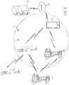
- FIG. 1 illustrates a communication system 100 that facilitates operation and control of multiple light devices and/or power tool devices through the use of an external device.
- the communication system 100 includes light devices 105a-b, power tool devices 110a-b, and at least one external device 115.
- the external device 115 is configured to communicate with a remote server 120 over a network 125.
- the external device 115 is configured to communicate with power tool devices 110a and light devices 105a that are within a direct communication range 130 of the external device 115.
- each light device 105a-b and each power tool device 110a-b within the communication system 100 is configured to communicate with other devices (e.g., the external device 115, another light device 105, another power tool device 110) that are within a communication range of the light device 105 or the power tool device 110, respectively.
- the communication range 130 of the external device 115 (and of the light devices 105 and the power tool devices 110) may change based on, for example, the communication protocol used by the external device 115 to communicate with the power tool devices 110a-b and the light devices 105a-b, obstructions between the external device 115 and the light devices 105a-b and the power tool devices 110a-b, power available to the external device 115, and other factors.
- the power tool devices 110a-b and the light devices 105a-b form a mesh network (e.g., a wireless ad hoc network) to extend the communication range 130 of the external device 115.
- a first power tool device 110a and a first light device 105a are within the communication range 130, while a second power tool device 110b and a second light device 105b are outside the communication range 130.
- the second power tool device 110b and the second light device 105b utilize the first power tool device 110a and/or the first light device 105a as communication bridges to communicate with the external device 115.
- the second power tool device 110b and/or the second light device 105b communicate with the first power tool device 110a and/or the first light device 105a.
- the first power tool device 110a and/or the first light device 105a then transmit the message to the external device 115.
- the external device 115 may send messages to the second light device 105b and/or the second power tool device 110b, and may use the first light device 105a and/or the first power tool device 110a as communication bridges to reach the second light device 105b and/or the second power tool device 110b. Therefore, light devices 105 outside the direct communication range 130 of the external device 115 may still be controlled and may communicate with the external device 115 by utilizing the mesh network.
- FIG. 2 illustrates an exemplary light device 105.
- the exemplary light device 105 of FIG. 2 is a self-standing vertical area light.
- the light device 105 (or some of the light devices 105) may have a different construction and may include different components.
- the light devices 105 may include mountable and/or compact flood lights, stick lights, site lights, flashlights, among others.
- the exemplary light device 105 of FIGS. 2 and 3 provides lighting capabilities as well as other functionality, for example, charging of battery packs, power outlets for other devices, environmental sensing, and the like.
- some of the light devices 105 may include some or none of the additional functionality listed above.
- the light device 105 includes a base 205, a light body 210, and a light head 215.
- the light body 210 and the light head 215 are supported by the base 205.
- the light body 210 houses a plurality of lights 220.
- the plurality of lights 220 may be divided into strips such that each strip may be controlled individually. In the illustrated embodiment, the plurality of lights 220 are LEDs.
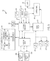
- FIG. 3 is a schematic diagram for the exemplary light device 105.
- the light device 105 includes an alternating current (AC) power input 225, AC power outlets 227, battery pack ports 230a-b, a power circuit 235, a charging circuit 240, control panel 245, a motion sensor 250, a location unit 255, an environmental sensor 257, a power sensor 260, a wireless communication controller 265, and an electronic processor 270.
- the AC power input 225 is configured to receive AC power from an external AC power source (e.g., a power distribution box, a household power outlet, a generator, and the like).
- the power received through the AC power input 225 can be provided to other electronic devices through the AC power outlets 227.
- the AC power outlets 227 may allow several light devices 105 to be daisy-chained from each other.
- the power received through the AC power input 225 is then transferred to the power circuit 235.
- the power circuit 235 receives the power from the AC power input 225 and converts it to power with specific characteristics to power components of the light device 105.
- the power circuit 235 may include an AC-to-DC converter, a filter, a rectifier, a step-down controller, a PWM control, and/or other components that change characteristics of the power received through the AC power input 225.
- the power circuit 235 is coupled to other components of the light device 105. In the illustrated embodiment, the power circuit 235 is coupled to the electronic processor 270, the charging circuit 240, and the lights 220.
- the power circuit 235 may provide different power outputs to each of the charging circuit 240, the electronic processor 270, and the lights 220.
- the power circuit 235 may provide sufficient current to charge one or more battery packs to the charging circuit 240, but may provide a significantly lower power rating to the electronic processor 270 and/or to the sensors 250, 255, 257, 260.
- the power circuit 235 may receive control signals from the electronic processor 270 to control the power provided to the lights 220.
- the charging circuit 240 provides charging power to the battery pack ports 230a-b.
- the battery pack ports 230a-b receive a slide-on battery pack.
- the battery pack ports 230a-b may receive a different type of battery pack, and/or each battery pack port 230a-b may be constructed differently to each receive a different type of battery pack.
- the power circuit 235 receives power from the battery pack ports 230a-b, and may, in such embodiments, power the lights 200 with power from a connected battery pack.
- some or all of the light devices 105 do not include the charging circuit 240, and may be configured to receive power through the battery pack ports 230a-b, but not recharge the connected battery packs.
- the control panel 245 allows a user to control the operation of the light device 105.
- the control panel 245 may include a combination of virtual and physical actuators.
- the control panel 245 includes a light intensity control 280, a light intensity indicator 283, and a state of charge indicator 285.
- the light intensity control 280 may also operate as a power button toggling the light device 105 on and off (e.g., by changing from a fully on state to a fully off state).
- the state of charge indicator 285 illustrates a relative state of charge of one or more of the connected battery packs.
- the state of charge indicator 285 includes a plurality of indicator bars that depict the level of charge of the connected battery packs.
- the light intensity control 280 may include, for example, a button. Each press of the light intensity control 280 changes the intensity of the lights 220. In some embodiments, when the light device 105 is powered through an external AC source, the light intensity control 280 rotates among six different light intensity levels, but when the light device 105 is powered through a DC power source (e.g., a battery pack), the light intensity control only rotates through three light intensity levels.
- the light intensity indicator 283 may include, for example, an LED that changes in brightness or flashing frequency based on the light intensity level of the light device 105. In some embodiments, the light intensity indicator 283 includes indicator bars that depict the light intensity level of the light device 105 by increasing or decreasing the number of indicator bars that are illuminated.
- the motion sensor 250 is coupled to the electronic processor 270.
- the motion sensor is configured to detect motion of an object within a proximity range of the light device 105.
- the motion sensor 250 can be active or passive.
- the motion sensors can include a passive infrared sensor (PIR) to detect when people come within range of the sensor.
- PIR passive infrared sensor
- the motion sensor 250 may detect changes in light and determine that an object moved when the change of light exceeds a predetermined threshold.
- other types of motion sensors 250 are used.
- the motion sensor 250 detects motion (e.g., of a person or an object)
- the motion sensor 250 generates and sends an activation signal to the electronic processor 270.
- the electronic processor 270 may then change an operation of the lights 220 in response to the detected motion, may transmit a message to the external device 115, or the like.
- the light device 105 do not include the motion sensor 250 described above.
- the location unit 255 includes, for example, a Global Positioning System (GPS) unit.
- the location unit 255 determines a location of the light device 105 and sends the determined location to the electronic processor 270.
- the light device 105 may not include a location unit 255 and may be configured to determine its location by communicating with other light devices 105 and/or with an external device 115.
- the environmental sensor 257 may include, for example, a carbon monoxide sensor, a gas buildup sensor, a humidity sensor, a dust sensor, and/or a similar sensor. The environmental sensor 257 detects when an environmental parameter is outside a predetermined threshold and generates an alert signal to the electronic processor 270.
- the electronic processor 270 may then generate a signal to alert the user that a particular environmental parameter is outside an expected range.
- Each light device 105 may include one, more, or no environmental sensors.
- the light device 105 may also include a power sensor 260.
- the power sensor 260 is coupled to the electronic processor 270 and, in some embodiments, is also coupled to the battery pack ports 230a-b and to the AC power input 225.
- the power sensor 260 detects the incoming power to the light device 105.
- the power sensor 260 also monitors and measures power consumption of the light device 105, and may be able to determine which components of the light device 105 are consuming more or less power.
- the power sensor 260 provides these measurements to the electronic processor 270.
- the wireless communication controller 265 is coupled to the electronic processor 270, and exchanges wireless messages with other light devices 105 in the communication system 100, the external device 115, and/or power tool devices 110 in the communication system 100.
- the wireless communication controller 265 includes a transceiver 290, a processor 293, and a real-time clock 295.
- the transceiver 290 sends and receives wireless messages to and from other light devices 105, power tool devices 110, and/or the external device 115.
- the wireless communication controller 265 also includes a memory.
- the memory stores instructions to be implemented by the processor 293 and/or data related to communications between the light device 105 and other devices of the communication system 100.
- the processor 293 of the wireless communication controller 265 controls wireless communications between the light device 105a and other devices within the communication system 100. For example, the processor 293 of the wireless communication controller 265 buffers incoming and/or outgoing data, communicates with the electronic processor 270, and determines the communication protocol and/or settings to use in wireless communications.
- the wireless communication controller 265 is a Bluetooth® controller.
- the Bluetooth® controller communicates with other devices (e.g., other light devices 105, external device 115, and/or power tool devices 110) employing the Bluetooth ® protocol.
- the wireless communication controller 265 communicates using other protocols (e.g., Wi-Fi, cellular protocols, a proprietary protocol, etc.) over different type of wireless networks.
- the wireless communication controller 265 may be configured to communicate via Wi-Fi through a wide area network such as the Internet or a local area network, or to communicate through a piconet (e.g., using infrared or NFC communications).
- the communication exchanged by the wireless communication controller 265 may be encrypted to protect the data exchanged between the light device 105 and the external device/network 115 from third parties.
- the wireless communication controller 265 receives data from the electronic processor 270 and prepares outgoing messages to other light devices 105, power tool devices 110, and/or to the external device 115. For example, the wireless communication controller 265 may send information regarding the outputs from the sensors 250, 255, 257, 260 of the light device 105, regarding the current operational parameters of the light device 105 (e.g., a current brightness, power consumption remaining runtime, and the like), enabled/disabled features of the light device 105, an identification signal and/or code for the particular light device 105, maintenance information for the light device 105, usage information for the light device 105, and the like.
- the wireless communication controller 265 may send information regarding the outputs from the sensors 250, 255, 257, 260 of the light device 105, regarding the current operational parameters of the light device 105 (e.g., a current brightness, power consumption remaining runtime, and the like), enabled/disabled features of the light device 105, an identification signal and/or code for the particular light
- the wireless communication controller 265 may send information, for example, regarding number of activations for a particular sensor 250, 255, 257, 260, data and time of the activations, raw data recorded and/or detected by the particular sensor 250, 255, 257, 260, and the like.
- the wireless communication controller 265 also receives wireless messages and/or commands from other light devices 105, power tool devices 110, and/or the external device 115.
- the wireless messages and/or commands from other devices may include programming and/or configuration information for the light device 105.
- the real-time clock (RTC) 295 increments and keeps time independently of the other components of the light device 105.
- the RTC 295 is coupled to a back-up power source, which provides power to the RTC 295 such that the RTC 295 continues to track time regardless of whether the light device 105 receives AC power, DC power (e.g., from a connected battery pack), or no power.
- the RTC 295 enables time stamping of operational data (e.g., which may be stored for later export) and, may, in some embodiments, enable a security feature whereby a lockout time is set by a user and the light device 105 is locked-out when the time of the RTC 295 exceeds the set lockout time.
- the processor 293 of the wireless communication controller 265 switches between operating in a connectable (e.g., full power) state and operating in an advertisement state.
- the wireless communication controller 265 switches between operating in the connectable state and the advertisement state based on whether the light device 105 receives power from an external source, or whether the light device 105 is disconnected from an external power source.
- the wireless communication controller 265 operates in the connectable state when the light device 105 receives power from an external AC power source.
- the wireless communication controller 265 also operates in the connectable state when the light device 105 receives power through one of the battery pack ports 230 and the connected battery pack holds sufficient charge (i.e., the voltage of the connected battery pack is above a threshold).
- the wireless communication controller 265 may receive power from the back-up power source, and operates in the advertisement state.
- the light device 105 When the wireless communication controller 265 operates in the advertisement state, the light device 105 generates and broadcasts an identification signal, but data exchange between the light device 105 is limited to select information.
- the wireless communication controller 265 outputs an advertisement message including identification information regarding the light device identity, remaining capacity of the back-up power source (e.g., if one is included), and other limited information about the light device.
- the advertisement message may also identify the product as being from a particular manufacturer or brand via a unique binary identification "UBID.”
- the unique binary identification UBID identifies the type of light device and also provides a unique identifier for the particular light device (e.g., a serial number). Therefore, the external device 115, and the light devices 105 and other power tool devices 110 can identify the light device 105 even when the wireless communication controller 265 operates in the advertisement state.
- the wireless communication controller 265 When the wireless communication controller 265 operates in the connectable state, full wireless communication between the light device 105 and other devices in the communication system 100 (e.g., power tool devices 110 and the external device 115) is enabled. From the connectable state, the wireless communication controller 265 can establish a communication link (e.g., pair) with another device (e.g., another light device 105, a power tool device 110, and/or the external device 115) to obtain and export usage data for the light device 105, maintenance data, operation mode information, outputs from the sensors 250, 255, 257, 260, and the like from the light device 105 (e.g., light device electronic processor 270). The exported information can be used by tool users or owners to log data related to a particular light device 105 or to specific job activities.
- a communication link e.g., pair
- another device e.g., another light device 105, a power tool device 110, and/or the external device 115
- the exported information can be used by
- the exported and logged data can indicate when the light device 105 was activated, and the power consumption of the light device 105.
- the logged data can also provide a chronological record of what areas were illuminated in a chronological order or in a geographical order.
- the wireless communication controller 265 While paired with another device (e.g., the external device 115, a power tool device 110, or another light device 105), the wireless communication controller 265 also imports (i.e., receives) information from the other devices (e.g., the external device 115, power tool device 110, and/or another light device 105) into the light device 105 such as, for example, configuration data, operation thresholds, maintenance threshold, configuring modes of operation of the light device, programming of the light device 105, programming for the light device 105, and the like.
- the electronic processor 270 is coupled to the wireless communication controller 265, the sensors 250, 255, 257, 260, the control panel 245, the power circuit 235, and the charging circuit 240.
- the electronic processor 270 receives detection outputs from each of the sensors 250, 255, 257, 260.
- the electronic processor 270 changes an operational parameter of the light device 105 such that the operation of the light device 105 is altered based on a detection from a sensor 250, 255, 257, 260.
- the electronic processor 270 may decrease the brightness of the lights 220 in response to detecting, via an environmental sensor 257, that the ambient light is above a threshold.
- the electronic processor 270 also stores (or sends to a memory for storage) some of the detection outputs from each of the sensors 250, 255, 257, 260, and may store additional information associated with the detection output (for example, time of detection, date of detection, and the like).
- the electronic processor 270 then controls the wireless communication controller 265 to send a wireless message to the external device 115 including information regarding one or more detection output from one of the sensors 250, 255, 257, 260.
- the wireless message may include an alarm message to the external device 115 (for example, when AC power to a light device 105 has been interrupted), or may be a notification message meant for updating information regarding the light device 105.
- the electronic processor 270 receives signals from the control panel 245 indicating which controls were actuated by the user. The electronic processor 270 then sends control signals to the power circuit 235 such that the appropriate power is transmitted to the lights 220 to illuminate them according to the instructions received through the control panel 245. For example, the electronic processor 270 may receive a signal from the control panel 245 indicating that the light intensity control 280 has been actuated to increase the brightness of the lights 220. The electronic processor 270 may then instruct the power circuit 235 to increase the power provided to the lights 220 such that the light intensity of the lights 220 increases.
- the electronic processor 270 also receives commands and control signals from the external device 115 through the wireless communication controller 265, and transmits corresponding control signals to the power circuit 235 based on the received commands and control signals.
- the electronic processor 270 sends the control signals to the power circuit 235 such that the lights 220 are illuminated according to the instructions received from the external device 115.
- each light device 105 may be part of a mesh network
- the electronic processor 270 determines whether the control signals and/or other communications received through the transceiver 165 include the light device 105 as a final recipient, and forwards any necessary communications from the external device 115 in which the light device 105 is not its final destination.
- a user can both control a light device 105 and/or access stored information regarding the light device 105.
- a user may access stored light usage maintenance data through the external device 115.
- the light device usage information may allow a user to determine how the light device 105 has been used, whether maintenance is recommended or has been performed in the past, and identify malfunctioning components or other reasons for certain performance issues.
- the external device 115 can also transmit data to the light device 105 for light configuration, firmware updates, or to send commands (e.g., turn on a light).
- the external device 115 also allows a user to set operational parameters, safety parameters, group lights together, and the like for the light device 105.
- FIG. 4 illustrates an exemplary power tool device 110.
- the power tool device 110 includes a power tool.
- the power tool device 110 may alternatively include a power tool battery pack, and/or a battery pack charger.
- the power tool device 110 may include different type(s) of power tools.
- the power tool device 110 is configured to perform one or more specific tasks (e.g., drilling, cutting, fastening, pressing, lubricant application, sanding, heating, grinding, bending, forming, impacting, polishing, charging, providing output power, and the like).
- the power tool device 110 includes an impact wrench being associated with the task of generating a rotational output (e.g., to drive a bit), while a reciprocating saw, for example, is associated with the task of generating a reciprocating output motion (e.g., for pushing and pulling a saw blade).
- the task(s) associated with a particular power tool device may also be referred to as the primary function(s) of the power tool device 110.
- the particular power tool devices 110 illustrated and described herein are merely representative.
- FIG. 1 Other embodiments of the communication system 100 include a variety of types of power tool devices 110 (e.g., a power drill, a hammer drill, a pipe cutter, a sander, a nailer, a grease gun, a charger, a battery pack, etc.).
- a power tool device 110 e.g., a power drill, a hammer drill, a pipe cutter, a sander, a nailer, a grease gun, a charger, a battery pack, etc.
- the exemplary power tool device 110 includes an output device 405, a mode pad 410, a trigger 420, a motor 425, a switching network 430, sensors 435, indicators 440, a battery pack interface 445, a power input unit 450, a tool electronic processor 455, and a tool communication controller 460.
- the power tool device 110 receives power through the battery pack interface 445.
- the battery pack interface 445 mechanically and electrically couples to a battery pack for the power tool device 110.
- the battery pack interface 445 is also coupled to the power input unit 450, and transmits the power received from the battery pack to the power input unit 450.
- the power input unit 450 includes active and/or passive components (e.g., voltage step-down controllers or transformers, voltage converters, rectifiers, filters, and the like) to regulate and/or control the power received through the battery pack interface 445 and to the tool communication controller 460 and the tool electronic processor 455.
- active and/or passive components e.g., voltage step-down controllers or transformers, voltage converters, rectifiers, filters, and the like
- the power input unit 450 then selectively provides power to the switching network 430 based on a user input received through the trigger 420 and/or the mode pad 410, as well as from control signals from the tool electronic processor 455.
- the switching network 430 enables the tool electronic processor 455 to control the operation of the motor 425.
- the trigger 420 is depressed (e.g., by a user)
- electrical current is supplied from the battery pack interface 445 to the motor 425, via the switching network 430.
- electrical current is not supplied from the battery pack interface 445 to the motor 425.
- the switching network 430 may include numerous FETs, bipolar transistors, or other types of electrical switches.
- the switching network 430 may include a six-FET bridge that receives pulse-width modulated (PWM) signals from the tool electronic processor 455 to drive the motor 425.
- PWM pulse-width modulated
- the motor 425 drives the output device 405.
- the output device 405 includes a socket.
- each power tool may have a different output device 405 specifically designed for the task (or primary function) associated with the power tool.
- the drive device for a power drill may include a bit driver, while the drive device for a pipe cutter may include a blade.
- the mode pad 410 receives a user input indicating a desired mode of operation of the power tool device 110. The mode pad 410 also indicates to the user a currently selected mode of operation for the power tool device 110.
- the power tool device 110 also includes sensors 435 that are coupled to the tool electronic processor 455.
- the sensors 435 communicate various signals indicative of different parameter of the power tool device 110.
- the sensors 435 include Hall Effect sensors 435a, current sensors 435b, among other sensors, such as one or more voltage sensors, temperature sensors, torque sensors, and the like.
- the Hall Effect sensors 435a output motor feedback information to the tool electronic processor 455.
- the current sensors 435b may output information regarding the load current experienced by the motor 425.
- the indicators 440 are also coupled to the tool electronic processor 455 and receive control signals from the tool electronic processor 455 to turn on and off, or otherwise convey information based on different states of the power tool device 110.
- the indicators 440 include, for example, one or more light-emitting diodes ("LED"), or a display screen.
- the indicators 440 can be configured to display conditions of, or information associated with, the power tool device 110.
- the indicators 440 are configured to indicate measured electrical characteristics of the power tool device 110, the status of the power tool device 110, the mode of the power tool device 110, etc.
- the indicators 440 may also include elements to convey information to a user through audible or tactile outputs.
- the tool electronic processor 455 is electrically and/or communicatively connected to a variety of modules or components of the power tool device 110.
- the tool electronic processor 455 includes a plurality of electrical and electronic components that provide power, operational control, and protection to the components and modules within the tool electronic processor 455 and/or power tool device 110.
- the tool electronic processor 455 includes, among other things, a processing unit (e.g., a microprocessor, a microcontroller, or another suitable programmable device), a memory 465, input units, and output units.
- the tool electronic processor 455 is implemented partially or entirely on a semiconductor (e.g., a field-programmable gate array ["FPGA"] semiconductor) chip, such as a chip developed through a register transfer level (“RTL”) design process.
- a semiconductor e.g., a field-programmable gate array ["FPGA"] semiconductor
- the memory 465 includes, for example, a program storage area 467a and a data storage area 467b.
- the program storage area 467a and the data storage area 467b can include combinations of different types of memory.
- the tool electronic processor 455 is connected to the memory 465 and executes software instructions that are capable of being stored in a RAM of the memory 465 (e.g., during execution), a ROM of the memory 465 (e.g., on a generally permanent basis), or another non-transitory computer readable medium such as another memory or a disc.
- Software included in the implementation of the power tool device 110 can be stored in the memory 465 of the power tool device 110.
- the software includes, for example, firmware, one or more applications, program data, filters, rules, one or more program modules, and other executable instructions.
- the tool electronic processor 455 is configured to retrieve from memory 465 and execute, among other things, instructions related to the control processes and methods described herein.
- the tool electronic processor 455 is also configured to store power tool device information on the memory 465 including operational data, information identifying the type of power tool device, a unique identifier for the particular tool device, and other information relevant to operating or maintaining the power tool device 110.
- the tool device usage information such as current levels, motor speed, motor acceleration, motor direction, number of impacts, may be captured or inferred from data output by the sensors 435. These tool device parameters are monitored by the tool electronic processor 455 to operate according to the mode selected via the mode pad 410.
- the tool electronic processor 455 includes additional, fewer, or different components.
- the tool communication controller 460 is coupled to the tool electronic processor 455 and exchanges wireless messages with other power tool devices 110 in the communication system 100, the external device 115, and/or light devices 105 in the communication system 100.
- the tool communication controller 460 includes a transceiver 470, a processor 475, and a real-time clock 480.
- the tool communication controller 460 is similar in construction and in operation to the wireless communication controller 265 described above with reference to the exemplary light device 105, and description of the wireless communication controller 265 therefore analogously applies to the tool communication controller 460.
- the tool communication controller 460 controls wireless communications between the power tool device 110 and other components of the communication system, includes a real-time clock 480 for time-stamping data received by the sensors 435, may operate using the Bluetooth ® protocol (or another wireless communication protocol), switches operation between an advertisement mode and a connectable mode based on the power source for the power tool device 110, and may be powered by a back-up power source.
- the advertisement state and the connectable state of the tool communication controller 460 are similar to that described above with respect to the wireless communication controller 265 of the light device 105. For example, when the tool communication controller 460 operates in the advertisement state, data communication with the power tool device 110 is limited (e.g., to, for example, identification and/or location information associated with the power tool device 110).
- the tool communication controller 460 when the tool communication controller 460 operates in the connectable state, full bidirectional data communication with the power tool device 110 is enabled. For example, in the connectable state, the tool communication controller 460 may transmit information regarding usage data, maintenance data, mode information, drive device information, and the like from the power tool device 110.
- the tool communication controller 460 operates in the advertisement state when the power tool device 110 is not connected to an external power source (e.g., is disconnected from a battery pack) or the connected power source does not have sufficient charge (e.g., the connected battery pack is nearly depleted).
- the tool communication controller 460 can switch to the connectable state when the external power source is connected to the power tool device 110 and hold sufficient charge to support bidirectional data exchange with the power tool device 110.
- the tool communication controller 460 is configured to communicate with other power tool devices 110, light devices 105, and/or the external device 115. In other embodiments, however, the tool communication controller 460 may not communicate with other power tool devices 110, and may instead use the mesh network of the light devices 105 to extend its communication range with the external device 115.
- the external device 115 Using the external device 115, a user can determine how the power tool device 110 has been used, whether maintenance is recommended or has been performed in the past, and identify malfunctioning components or other reasons for certain performance issues.
- the external device 115 can also transmit data to the power tool device 110 for power tool configuration, firmware updates, or to send commands (e.g., turn on a work light).
- the external device 115 also allows a user to set operational parameters, safety parameters, select tool modes, and the like for the power tool device 110.
- the exemplary power tool device 110 of FIG. 4 is described as a power tool.
- the power tool device may be a charger or a battery pack.
- the power tool device 110 may not include a motor 425 and/or a switching network 430, and the output device 405 may include the battery terminals configured to transfer power.
- the sensors 435 do not measure the position of the motor, and may instead measure, for example, other parameters of a battery pack charger and/or a power tool battery pack, and may transmit corresponding information to the tool electronic processor 455.
- FIG. 5 illustrates a schematic diagram of the external device 115.
- the external device 115 includes a memory 505 storing core application software 507, temporary configuration data 510 for the light devices 105 and the power tool devices 110, device interfaces 515 (e.g., interfaces for light devices and power tool devices), device data 520 including received power tool device identifiers, light device identifiers, power tool device operational data, light device operational data, location information for light devices 105 and power tool devices 110, identification information for the light devices 105 and the power tool devices 110, and the like.
- the external device 115 further includes an electronic processor 525, a touch screen display 530, and an external wireless communication controller 535.
- the touch screen display 530 allows the external device 115 to output visual data to a user and receive user inputs.
- the electronic processor 525 may generate a graphical user interface to display usage information for a light device 105 on the touch screen display 530.
- the touch screen display 530 may then also receive user inputs (e.g., through interactions with the graphical user interface), and transmit the user inputs to the electronic processor 525.
- the external device 115 may include other input devices (e.g., buttons, dials, toggle switches, and a microphone for voice control) and other output devices (e.g., speakers and tactile feedback elements). Additionally, in some instances, the external device 115 has a display without touch screen input capability and receives user input via other input devices, such as buttons, dials, and toggle switches.
- the external device 115 communicates wirelessly with the transceiver of the light device 105 and/or the power tool device 110 via the external wireless communication controller of the external device 115, e.g., using a Bluetooth® or Wi-Fi® protocol.
- the external device 115 further communicates with the remote server 120 through network 125.
- the external device 115 includes two separate wireless communication controllers, one for communicating with the power tool devices 110 and the light devices 105 (e.g., using Bluetooth® or Wi-Fi® communications) and one for communicating with the remote server 120 (e.g., using Wi-Fi or cellular communications).
- the server 120 includes a processor that communicates with the external device 115 over the network 125 using a network interface.
- the communication link between the network interface, the network 125, and the external device 115 may include various wired and wireless communication pathways, various network components, and various communication protocols.
- the server 120 further includes a memory including a tool profile bank and tool data, as well as light identification, usage, and operational data.
- the server 120 provides the ability to store a larger amount of data than would be stored in the external device 115, as well as the ability for the user to access the data from a different external device 115 than the one used to transmit data to the server 120.
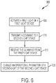
- FIG. 6 is a flowchart illustrating a process 600 for transmitting commands from a first device (e.g., a first light device 105a) to a second device (e.g., a second light device 105b) of the communication system 100.
- the first light device 105a includes a first light that is activated by the electronic processor 270 of the first light device 105a (step 605).
- the electronic processor 270 of the first light device 105a then transmits a command to a second light device 105b via a first wireless communication controller 265 of the first light device 105a (step 610).
- the command instructs the second light device 105b to change an operational parameter of a second light of the second light device 105b.
- the wireless communication controller 265 of the second light device 105b receives the command from the first light device 105a (step 615).
- the electronic processor 270 of the second light device 105b determines that the command instructs the second light device 105b to change an operational parameter of the second light.
- the electronic processor 270 of the second light device 105b then changes an operational parameter of the second light in response to receiving the command through the first light device 105a.
- the operational parameter may include, for example, a pre-programmed runtime for the second light, a brightness associated with the second light, an enabled or disabled feature associated with the second light device 105b, a power consumption of the second light device 105b, an associated application for the second light device 105b, a combination thereof, and/or any of the parameters discussed above with respect to the exemplary light device 105.
- the command may instruct the second light device 105a to turn the second light on.
- the command includes changes to multiple operational parameters.
- the command may be referred to as new configuration data, since the second light device 105b is re-configured based on the received command from the first light device 105a.
- the command from the first light device 105a originates at the first light device 105a based on a received input through, for example, the control panel 245.
- the command originates from the external device 115, but uses the first light device 105a as a communication bridge between the external device 115 and the second light device 105b.
- FIG. 7 is a flowchart illustrating a method 700 for transmitting a command to a light device 105 from an external device 115.
- the external device 115 performs a scan for nearby devices (step 705).
- the external device 115 receives an advertisement signal (e.g., an identification signal) from each nearby device in the communication system 100.
- an advertisement signal e.g., an identification signal
- the external device 115 displays on its touch screen display 530, a list of the nearby devices (step 710).
- the list of nearby devices only includes those devices (e.g., light devices 105 and/or power tool devices 110) that are within the direct communication range 130 of the external device 115.
- the list of nearby devices would only include the first light device 105 and the first power tool device 110a because the second light device 105b and the second power tool device 110b are not within the direct communication range 130 of the external device 115.
- the list of nearby devices includes any device (e.g., light devices 105 and power tool devices 110) that is in communication with the external device 115 (e.g., has a communication path to the external device 115).
- the list of nearby devices would include the first light device 105a, the second light device 105b, the first power tool device 110a, and the second power tool device 110b.
- FIG. 8 illustrates an exemplary screenshot of a list 713 of nearby devices displayed on the external device 115.
- the list 713 of nearby devices includes any device with which the external device 115 can establish a communication path.
- the external device 115 via the touch screen display 530, receives a selection of a device from the list of nearby devices (step 715).
- the external device 115 includes a touch screen, and the selection is received by an actuation of the touch screen. Because each device within the communication system 100 is different, may operate differently, and may include different components, the external device 115 (i.e., a device electronic processor) configures a settings screen for the selected device based on the information of the selected device. In some embodiments, the external device 115 may communicate with the server 120 to configure the settings screen for the selected device based on identification information of the selected device.
- the selected device is a selected light device 105 (e.g., the first light device 105a, the second light device 105b, or a different light device), and a device electronic processor of the external device 115 displays settings screen associated with the selected light device 105 (step 720).
- a selected light device 105 e.g., the first light device 105a, the second light device 105b, or a different light device
- a device electronic processor of the external device 115 displays settings screen associated with the selected light device 105 (step 720).
- a home screen for the selected device is displayed on the external device 115 before displaying the settings screen for the selected device.
- FIG. 9 illustrates an exemplary screenshot of a home screen 722 for the selected light device 105.
- the home screen 722 displays options for the user to manage the interaction with the selected light device 105.
- the home screen 722 includes a light controls option 725, a group manager option 730, a locate option 735, and a factory reset option 740.
- the home screen 722 also includes an icon 745 for the particular device (in this example, the selected light device 105). This icon 745 may be the same icon displayed on the list 713 of nearby devices in FIG. 8 .
- the factory reset option 740 causes the external device 115 to obtain default values for the operational parameters of the selected device (e.g., from the server 120 and/or from the selected light device 105 itself), and provides the default values to the selected light device 105, which overwrites any current values of the operational parameters for the selected light device 105 (or another selected device).
- the location option 735 is described in more detail below with respect to FIGS. 16-19 , while the group manager option is described in more detail with respect to FIG. 11 .
- FIG. 10 is an exemplary screenshot of a settings screen 750 for the selected light device 105.
- the exemplary settings screen 750 includes a pre-set application parameter 752, a dimmer parameter 754, a tracking feature parameter 756, a schedule parameter 758, a don't blind me feature parameter 760, and an ambient light feature parameter 762.
- the settings screen 750 also displays some power consumption metrics 764, and provides an option to request more information 766.
- Each of the parameters displayed on the settings screen 750 may be manipulated by a user. For example, a user can change the pre-set application between a drywall application, a paint application, an outdoor application, and in some embodiments, additional application options may be provided. Each application is associated with a particular brightness of the selected light device, and/or a hue or color of the selected light device. In some embodiments, each application may additionally or alternatively be associated with a particular runtime, and/or a particular power consumption.
- the dimmer parameter 754 also allows a user to specify the dimming level or the brightness level for the selected light device 105.
- a user may select, via a slider, whether the first light of the selected light device 105 is at its maximum brightness (e.g., fully on or 100% brightness), at its minimum brightness (e.g., fully off or 0% brightness), or at any other level in between.
- the tracking feature parameter 756 allows the user to toggle the tracking feature on and off.
- the tracking feature allows the selected light device 105 to operate as a tracking light and provide information to the external device 115 and the server 120 regarding the presence and/or movement of other devices within the communication network. The operation of the selected light device 105 as a tracking light is explained in more detail with reference to FIGS. 16-19 .
- the schedule parameter 758 allows a user to specify a particular lighting schedule for the selected light device 105.
- the user may specify different periods (each period including a start time and an end time) and an associated brightness or dimming level for that period.
- FIG. 10 illustrates a period starting at 8am and ending at 7pm during which the selected light device 105 operates at 30% brightness.
- a number of different periods may be added such that the brightness level of the first light changes based on time of day.
- Another feature selectable for the selected light device 105 through the settings screen 750 includes an economy plan feature 759.
- the economy plan feature 759 controls the brightness of the light such that overall power consumption of the selected light device 105, and, in some embodiments, of the devices of the communication system 100 is reduced. This may include, for example, rotating which light devices are turned off during certain period of time, reducing overall brightness in each of the light devices 105 (e.g., decreasing brightness by 15% when an economy mode is selected), and the like.
- the don't blind me feature parameter 760 allows the user to toggle the don't blind me feature on and off.
- the selected light device 105 detects when a headlight is focused on the selected light device 105.
- the selected light device 105 may use one or more of the environmental sensors to detect whether additional light is pointed toward the first light device 105.
- the selected light device 105 determines that additional light is pointed toward the first light device 105, and therefore a headlight is focused on the selected light device 105, the selected light device 105 automatically lowers its brightness level to inhibit blinding a person using a headlight that is pointed toward the selected light device 105.
- the first light device 105 determines that a headlight is pointed toward the selected light device 105 when a light sensor detects a higher than normal brightness at the selected light device 105.
- the ambient light feature parameter 762 allows the user to toggle the ambient light feature on and off.
- the selected light device 105 i.e., the electronic processor 270 of the selected light device 105 detects when an amount of ambient light increases and decreases and changes the brightness of the first light of the selected light device 105 correspondingly. For example, when the electronic processor 270 of the selected light device 105 detects that the ambient light is above a predetermined high ambient light threshold, the electronic processor 270 of the selected light device 105 decreases the brightness of the first light by approximately 50%.
- the electronic processor 270 of the selected light device 105 detects that the ambient light is below a predetermined low ambient light threshold, the electronic processor 270 of the selected light device 105 increases the brightness of the first light by approximately 50%.
- the electronic processor 270 of the selected light device 105 may linearly change the brightness of the first light inversely proportional to the ambient light detected by the electronic processor 270 of the selected light device 105.
- the ambient light feature may provide some power savings as well as providing an ability to maintain a relatively even level of brightness by compensating for the outdoor environment.
- the settings screen 750 may also provide the user with the opportunity to obtain further information regarding the selected light device 105.
- the settings screen 750 displays the power consumption metrics 764 including an average power consumption of the selected light device 105, an estimate of the remaining runtime, and an estimate of the remaining power of a battery pack coupled to the selected light device 105 (e.g., the state of charge of a battery pack coupled to the selected light device 105).
- more, less, or different power consumption metrics may be displayed to the user to provide some feedback regarding the power consumption of the selected light device 105.
- the settings screen 750 also includes an option to obtain further historical power consumption information for the selected light device 105. More information regarding the selected light device 105 and/or motion detected by the selected light device 105 may be requested by the user by actuating the obtain more information actuator 766.
- the external device 115 may directly control the selected light device 105 by toggling the selected light device 105 on/off. In some applications and/or circumstances, the external device 115 receives a user input indicating that the selected light device 105 is to flash, for example, three times. Users near the selected light device 105 may have been previously trained to know that flashing of the selected light device was indicative of a particular event. For example, in some situations, the flashing of a selected light device 105 may indicate that an assembly line is starting or stopping soon, that a security alarm was enabled, and the like.
- a user may select to change any (or combinations of) the parameters described above with reference to FIG. 10 .
- the external device 115 i.e., the electronic processor of the external device 115
- receives the user inputs step 770.
- the command transmitted by the external device 115 includes a destination address that corresponds to the address of the selected light device 105.
- the first light device 105a Since the first light device 105a is within the communication range of the external device 115, the first light device 105a receives the command for the selected light device 105 (step 780).
- the external device 115 transmits the command to one or more of the devices (e.g., light devices 105 and/or power tool devices 110) that are within the direct communication range of the external device 115, and allows the mesh network of the communication system 100 to deliver the command to the selected light device 105.
- the devices e.g., light devices 105 and/or power tool devices 110
- the external device 115 first determines whether the selected light device 105 is within the direct communication range of the external device 115. When the selected light device is within the communication range of the external device 115, the external device 115 sends the command directly to the selected light device 105. On the other hand, when the external device 115 determines that the selected light device 105 is not within the direct communication range of the external device 115, the external device 115 sends the command to a light device 105 within its communication range. In this example, the external device 115 sends the command to the first light device 105a because the first light device 105a is within the communication range of the external device 115.
- the electronic processor 270 of the first light device 105a upon receiving the command, determines whether the destination address of the received command from the external device 115 includes the address of the first light device 105a (step 785). In other words, the first light device 105a determines whether the command from the external device 115 is for the first light device 105a.
- the electronic processor 270 of the first light device 105a determines that the destination address includes the address of the first light device 105a (e.g., the selected light device 105 is the first light device 105a)
- the electronic processor 270 of the first light device 105a changes the operational parameter of the first light based on the command received from the external device 115 (step 790).
- the wireless communication controller 265 of the first light device 105a forwards the command to the second light device 105b (step 795).
- the second light device 105b receives the command, and determines whether the destination address includes the address of the second light device 105b. Such a forwarding process continues until the command reaches the selected light device 105.
- the light devices 105 of the communication system 100 may implement different routing algorithms to decide where to forward wireless messages when the receiving light device 105 is not included in the final destination of a wireless message.
- FIGS. 6 and 7 were described assuming that both communicating devices included light devices 105.
- the external device 115 may be used to change and/or re-configure a selected power tool device 110.
- the external device 115 may generate a separate settings screen (or control screen) for each power tool device 110 that conforms to the features available for the particular power tool device 110.
- a power tool device 110 could also substitute the first light device 105a and/or the second light device 105b described with respect to FIG. 6 .
- a first light device 105a may send a command to a power tool device 110 (e.g., using the first light device 105a as a communication bridge), a power tool device 110 may send a command to a second light device 105b (e.g., using the power tool device 110 as a communication bridge), and/or a first power tool device 110a may send a command to a second power tool device 110b.
- parameters such as rotating speed, applied torque, rotation direction, number of impacts, provided current and more may be customizable for a power tool device 110 through a settings screen displayed on the external device 115.
- Light devices 105 and/or other power tool devices 110 may then be used as communication bridges between the external device 115 and a selected power tool device 110.
- a plurality of light devices 105 may be grouped together (e.g., by a user or by default) such that changes to the operational parameter(s) affect each light device 105 in the group of the light devices 105.
- the group manager option 730 allows a user to group and re-group different number of light devices 105 such that they can be controlled simultaneously. The similar parameters are available to a group of light devices 105 than to a single light device 105.
- the external device 115 may send a command directly to each of the light devices 105 within the group of light devices 105. In other embodiments, however, the external device 115 transmits the command to a single light device 105 within its communication range, and the command reaches each of the light devices 105 in the group through the mesh network.
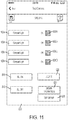
- FIG. 11 is an exemplary screenshot of a control screen 800 for a group A of light devices 105a-d.
- the groups may be based on, for example, the energy source for the light devices 105 (e.g., a set of light devices may share the same power source).
- the power source may include a battery, an AC outlet, a power tool battery pack, and the like.
- the control screen 800 includes on/off actuators 805a-d for each of the light devices 105a-d in the group A to turn on/off each of the light devices 105a-d individually.
- the control screen 800 also provides an "all on” control 810, and an "all off' control 815 to control all of the light devices 105a-d in the group simultaneously.
- a locate option 820 is available and may provide location information for one or more of the light devices 105a-d of the group A, as described in more detail below with reference to FIGS. 16-19 .
- the group A of light devices 105a-d may also be edited by selecting the "edit group” option 825. By activating the "edit group” option, specific light devices 105a-d may be added and/or deleted from the group A. Additional information may also be requested from the light devices 105a-d and/or from the server 120 through the "obtain information" option 830.
- FIG. 12 illustrates an exemplary screenshot of additional information available for at least one of the light devices 105 of the group A. As shown in FIG.
- the external device 115 may display a motion graph 835 that provides information regarding motion detected by the motion sensor 250 of a light device 105, as well as a brightness graph 840 that displays the relative brightness provided by the light device 105 throughout the day.
- the external device 115 also displays an environmental data graph 845 depicting values obtained from the environmental sensor 257 of a light device 105.
- the external device 115 may obtain the shown information by communication directly from the light device 105, or may request the information from the server 120.
- FIG. 13 is a flowchart illustrating a method 850 of forwarding commands to a group of light devices 105.
- the flowchart of FIG. 13 follows, for example, from step 790 of FIG. 7 .
- the electronic processor 270 of the first light device 105a determines whether the destination address includes a group of light devices (e.g., instead of only the address of the first light device 105a) at step 855.
- the wireless communication controller 265 of the first light device 105a forwards the command to the second light device 105b.
- the second light device 105b may then have to determine whether the destination address of the command includes the address of the second light command (step 860). However, when the destination address does not include a group of light devices 105 (e.g., and the command was instead directed only at the first light device 105a), the first light device 105a continues operation of the first light device 105a and continues monitoring for incoming wireless messages from other devices within the communication system 100 (step 865).
- the destination address does not include a group of light devices 105 (e.g., and the command was instead directed only at the first light device 105a)
- the first light device 105a continues operation of the first light device 105a and continues monitoring for incoming wireless messages from other devices within the communication system 100 (step 865).
- FIGS. 6-13 illustrate methods and screenshots related to using an external device 115 to reconfigure and/or change operational parameters of the light devices 105. Communication with the external device 115 by the light devices 105, however, is also useful to access operational information (e.g., metrics) regarding the light devices 105 and/or power tool devices 110.
- FIG. 14 is a flowchart illustrating a method 900 of transmitting a message to the external device 115 from a device (e.g., a light device 105 and/or a power tool device 110) of the communication system 100. In the example of the method 900, the first light device 105 sends the message to the external device 115.
- a device e.g., a light device 105 and/or a power tool device 110
- other devices in the communication system 100 may send the wireless message to the external device 115.
- the electronic processor 270 of the first light device 105a receives a communication trigger signal (step 905).
- a communication trigger signal represents a signal that upon receipt is to be communicated to the external device 115.
- a communication trigger signal may be an external signal received from a different light device 105 and/or power tool device 110, or may be an internal signal generated by the first light device 105 itself.
- an external signal may include a wireless message received from another light device 105 or power tool device 110 (e.g., from the second light device 105b) and that includes the address of the external device 115 as its destination address.
- the first light device 105a receives a message directed to the external device 115 (or another device in the communication system 100), the message is considered a communication trigger signal because it triggers the first light device 105a to transmit a wireless message to another device and/or the external device 115.
- the internal communication trigger signal may include a determination by the electronic processor 270 of the first light device 105a that an output from a sensor 250, 255, 257, 260 exceeds a predetermined sensor alert threshold.
- the electronic processor 270 of the first light device 105a may automatically generate an alert message to the external device 115 indicating that a particular parameter (e.g., an environmental parameter) exceeds an expected value and/or range.
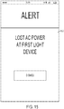
- the power sensor 260 detects that AC power to the first light device 105a has been interrupted
- the electronic processor 270 of the first light device 105a prepares an alert message to the external device 115 that AC power has been interrupted at the first light device 105a.
- the motion sensor may detect motion (or repeated motion) near the first light device 105a, which may prompt the electronic processor 270 of the first light device 105a to prepare a different alert message to the external device 115.
- the light device 105 communicates with the external device 115 when a battery pack needs replacement and/or when a battery is fully charged.
- Other internal or external signals that prompt the electronic processor 270 of the first light device 105a to prepare a message to the external device 115 may be considered communication trigger signals.
- a communication trigger signal may additionally trigger a change in the operation of the device.
- the brightness level of the light is automatically reduced in response to the output from the power sensor 260.
- the light device 105 may automatically (e.g., in response to detecting the proximity to the power tool device 110) activate its light and/or direct the light toward the direction in which the power tool device 110 is located relative to the light device 105.
- the electronic processor 270 of the first light device 105a constructs an appropriate wireless message to the external device 115 (step 910).
- the content of the wireless message is based on the communication trigger signal. For example, when the communication trigger signal includes a wireless message received from another device (e.g., the second light device 105b) in the communication system 100, the wireless message to the external device 115 includes the original wireless message (e.g., from the second light device 105b).
- the wireless message to the external device 115 includes an indication of which environmental parameter is outside an expected range.
- the wireless communication controller 265 of the first light device 105a determines whether the external device 115 is within the communication range of the first device 105a (step 915). When the external device 115 is within the direct communication range of the first device 105a, the wireless communication controller 265 of the first light device 105a transmits the message to the external device 115 directly (step 920).
- the wireless communication controller 265 of the first light device 105a transmits the message to the second light device 105b including instructions (e.g., a destination address) that specify that the wireless message is directed to the external device 115 (step 925).
- the second light device 105b then receives the wireless message, and determines whether the external device 115 is within the direct communication range of the second light device 105b (step 930). Although not shown, in some embodiments, the second light device 105b also determines whether the destination of the wireless message includes the address of the second light device. Since the destination address of the wireless message does not include the address of the second light device, the electronic processor 270 of the second light device 105 proceeds to determining whether the external device 115 is within the direct communication range of the second light device 105b.
- the wireless communication controller 265 of the second light device 105b transmits the message to the external device 115 (step 935).
- the second light device 105b e.g., the communication controller 265 of the second light device 115
- the 15 illustrates an exemplary screenshot of an alert message 950 sent to the external device 115 from the first light device 105a.
- the alert message 950 indicates that AC power was lost at the first light device 105a (e.g., the communication trigger signal was caused by the power sensor 260).
- FIG. 16 is a flowchart illustrating a method 1000 of updating the external device 115 regarding motion detected by a light device (for example, the first light device 105a).
- the first light device 105a detects motion within a proximity range of the first light device (step 1005).
- the first light device 105a determines the source of the movement (step 1010).
- the electronic processor 270 of the first light device 105a determines whether the detected motion is, for example, from a nearby power tool device 110 and/or from a nearby external device 115.
- the electronic processor 270 of the first light device 105a After the electronic processor 270 of the first light device 105a identifies the source of movement, the electronic processor 270 of the first light device 105a constructs the message to the external device 115 including a location and/or movement signal (step 1015). As discussed above, in some embodiments, detection of motion at the first light device 105a also prompts the electronic processor 270 of the first light device 105a to change a parameter of the first light device 105a. In one embodiment, when a light device 105 detects a power tool device 110 within a specified proximity range, the light device 105 may automatically (e.g., in response to detecting the proximity to the power tool device 110) activate its light and/or direct the light toward the direction in which the power tool device 110 is located relative to the light device 105.
- the light device 105 may automatically (e.g., in response to detecting the proximity to the power tool device 110) activate its light and/or direct the light toward the direction in which the power tool device 110 is located
- the location and/or movement signal includes an indication of the location of the first light device 105a and an indication of the power tool device 110 and/or the external device 115 located proximate to the first light device 105a.
- the location of the first light device 105a is obtained through the location unit 255.
- the location of the first light device is a relative location that indicates the location of the first light device 105a relative to other light devices in the communication system 100.
- the external device 115 receives the wireless message including the location and/or movement signal (step 1020), and transmits the location and/or movement signal to the remote server 120 (step 1025).
- the remote server 120 stores, among other things, a most recent location for each of the devices in the communication system 100.
- the remote server 120 may include a database in which the location of the light devices 105 and the power tool devices 110 is updated periodically.
- the remote server 120 receives the location and/or movement signal from the external device 115, the remote server 120 updates the location associated with the light device 105 or the power tool device 110 detected by the first light device 105a (step 1030).
- the different light devices 105 may serve to continuously track the power tool devices 110, other light devices 105, and/or the external devices 115 that are part of the communication system 100.
- the communication system 100 may also be able to monitor the well-being of its users. For example, if a particular user is associated with a first external device 115 and a nearby light device 105 detects that the first external device 115 has not changed location in more than, for example, three hours, the nearby light device 105 may transmit an alert signal to another external device 115 indicating that a particular user may need assistance.
- the first light device 105a may detect motion using different methods. For example, in one embodiment, the first light device 105a detects the motion through the motion sensor 250. In response to the motion detected by the motion sensor 250, the electronic processor 270 of the first light device 105a performs a scan of nearby devices to determine whether a power tool device 110, another light device 105, and/or an external device 115 are located nearby. In some embodiments, the first light device 105a may establish communication links with the nearby devices to monitor the received signal strength to determine which, if any, of the nearby devices generated the motion signal. In other embodiments, the first light device 105a (and at least some other light devices) perform a scan of the nearby devices.
- the first light device 105a then receives identification signals from each of the nearby devices 105, 110, 115.
- the first light device 105a then periodically repeats the scan (e.g., approximately every hour) and transmits the information regarding the nearby devices to the external device 115 on every scan. Therefore, when a particular power tool device 110, for example, is first detected by the first light device 105a, 30 minutes later by a second light device 105b, and 60 minutes later by a third light device 105, the electronic processor of the external device 115 and/or an electronic processor at the server 120 may determine a movement path (directional motion) of the power tool device 110.
- the first light device 105a may send an alert signal to the external device 115.
- At least some of the light devices 105 may operate as a tracking light and may move (e.g., with a small motor of the light device 105) in accordance to movement sensed within the particular room such that light is directed toward the source of motion.
- FIG. 17 is a flowchart illustrating a method 1100 of requesting location information for a device (e.g., a power tool device, a light device 105, and/or an external device 115) of the communication system 100.
- the external device 115 receives a selection to locate a power tool device 110 and/or a light device 105 (step 1105).
- the request to locate a power tool device 110 and/or a light device 105 may be received from different screens displayed by the external device 115.
- the external device 115 may then communicate with the server 120 and may receive a location signal from the server 120 (step 1110). The external device 115 then generates a map display based on the received location signal (step 1115).
- FIGS. 18 and 19 illustrate exemplary screenshots of mappings provided to provide the user with information regarding the location of the selected power tool devices 110 and/or light devices 105. As shown in FIGS. 18 and 19 , the mapping also provides an indication of the direction of where the power tool device 110 ( FIG. 18 ) and/or the light device 105 ( FIG. 19 ) with respect to either the current location of the external device 115 and/or the location of the nearest light device 105 and/or power tool device 110.
- the external device 115 does not access the server 120 to obtain the location information. Rather, the external device 115 sends a communication signal to one of the power tool devices and the light devices 105. Due to the mesh network configuration of the communication system 100, the request for the location of a particular power tool device 110 is propagated through the mesh network. When the particular power tool device 110 is found, a notification may, in some embodiments, be provided to the external device 115. In some embodiments, selecting the locate option 735 sends a command to the paired light device (e.g., the first light device 105a) requesting that the paired device provides a user-perceptible indication, such as flashing a light, lighting a different indicator or LEDs, making a sound.
- the paired light device e.g., the first light device 105a
- the external device 115 may receive more than one indication that the power tool device 110 has been located (e.g., if the power tool device 110 is in the communication range of more than one light device 105) and may determine at least a relative position of the power tool device 110 based on the information received from the light devices 105 (e.g., through triangulation).
- some of the light devices 105 are grouped together when they are associated with a particular egress. These light devices 105 may remain on at a non-zero brightness level regardless of the surrounding conditions to continue to illuminate the egress. These light devices 105 may also flash to indicate a path direction of egress.
- the light devices 105 can also respond to proximity signals. For example, if the light device 105 detects that a user is nearby, the light device 105 powers one. When the user is no longer within range (or within a specific area), the light device powers off.
- the light devices 105 include tracking lights that move a lighting head in the direction of movement or detected proximity. In some embodiments, the tracking lights may alternatively or additionally change the intensity of the bulbs in the direction of movement or detected proximity.
- FIG. 20 illustrates an exemplary screenshot of an alternative settings screen 1150 for a light device 105 of the communication system 100. Similar to the setting screen 750 of FIG. 10 , the settings screen 1150 of FIGS. 20A and 20B illustrate different parameters associated with the light device 105 that may be controlled by a user through the graphical user interface generated by the external device 115. As shown in FIG. 20A , the setting screen 1150 includes an on/off toggle 1153, a battery state indicator section 1156, an alert section 1159, and a brightness/runtime selector 1162. The on/off toggle 1153 allows a user to remote control whether the light device 105 is turned on or off. The on/off toggle 1153 moves between two positions: an on position and an off position.
- the on/off toggle 1153 is in the off position in FIG. 20A and in the on position in FIG. 20B .
- the graphical user interface provides an indication (e.g., a green colored light) when the on/off toggle 1153 is in the on position, so the user can easily identify the current state of the light device 105.
- the battery state indication section 1156 provides information regarding the current state of charge of the battery packs connected to the light device 105.
- the battery state indication section 1156 includes a battery icon 1164a-b for each battery pack connected to the light device 105. Each battery icon 1164a-b may indicate the state of charge for a battery pack connected to the light device 105. In some embodiments, the battery icons 1164a-b may change colors and may be filled to different levels based on the current state of charge. The graphical representation allows a user to quickly determine the battery state of the light device 105.
- the alert section 1159 provides information regarding abnormal conditions of the light device 105. In the illustrated embodiment, the alert section 1159 displays an alert regarding an abnormal condition for a battery pack connected to the light device. In other embodiments, however, the alert section 1159 may be related to other types of abnormal conditions such as, for example, a light 220 that is not working.
- the brightness/runtime selector 1162 allow a user to select a brightness or a runtime and provides a corresponding runtime or brightness, respectively. As shown in FIG. 20A , when the light device 105 is off, the brightness/runtime selector 1162 is deactivated. The settings screen 1150, however, displays instructions to turn the light device 105 on if the brightness/runtime selector 1162 is desired. FIG. 20B illustrates another instance of the settings screen 1150 in which the on/off toggle 1153 indicates that the light device 105 is activated, and the brightness/runtime selector 1162 is enabled. As shown in FIG. 20B , the brightness/runtime selector 1162 includes a parameter selector 1165a, a slider 1165b, and an indicator 1165c.
- the parameter selector 1165a toggles between brightness (or illumination level) and time to indicate which parameters may be controlled other than the parameter currently controlled by the brightness/runtime control 1165. For example, in the example of FIG. 20B , the brightness parameter is selected to be controlled.
- the parameter selector 1165a indicates "time" because an approximate runtime is the other parameter that may be controlled other than brightness, which corresponds to the parameter currently controlled by the brightness/runtime control 1165.
- the slider 1165b includes two ends indicating two extremes of the controlled parameter. In the example of FIG.
- the controlled parameter is brightness, so a first end of the slider 1165b corresponds to 0% brightness (e.g., light device 105 off) and a second, opposite end of the slider 1165b corresponds to 100% brightness (e.g., light device 105 fully on).
- the first end of the slider 1165b may correspond to a runtime of zero minutes (e.g., light device 105 off) and the second end of the slider 1165b may correspond to a maximum runtime associated with the light device 105.
- the indicator 1165c is movable along the slider 1165c to indicate a desired value for the controlled parameter (e.g., selects a desired brightness).
- the settings screen 1150 updates based on the desired value for the controlled parameter and displays a calculated parameter (e.g., an estimated runtime in the example of FIG. 20B ). The user may then have a reasonable approximation of how long the light device 105 is expected to be activated and at what brightness.
- a calculated parameter e.g., an estimated runtime in the example of FIG. 20B
- the brightness/runtime control may include different selection mechanisms in addition to or instead of the slider shown in FIG. 20B .
- the brightness/runtime control 1165 may provide a dropdown menu for a user to select a particular level of brightness or a runtime.
- the dropdown menu may present preset options. For example, a user may select a level of brightness from a dropdown menu presenting ten options such as, for example, 10%, 20%, 30%, 40%, 50%, and the like.
- the brightness/runtime control 1165 may allow a user to directly input the desired level of brightness and/or the desired runtime.
- a user may be able to input a desired level of brightness of 37%, and/or a runtime of 2 hours and 43 minutes.
- the brightness/runtime control 1165 may change based on which parameter is selected by the user. For example, when a user indicates a desired brightness, the slider may be displayed, but when a user indicates a desired runtime, a dropdown menu with different timing options may be displayed.
- the settings screen 1150 also includes an alert settings 1168.
- the alert settings 1168 may indicate, for example, what type of alerts are desired by the user, and may be able to tailor the alerts based on personal preferences of the users.
- the alert settings 1168 allow a user to specify when to be alerted that the light device 105 is expected to deactivate. In the illustrated embodiment, a selection of 30 minutes indicates that 30 minutes before the light device 105 is expected to deactivate, an alert is generated by the external device 115 to indicate that in approximately 30 minutes, the light device 105 was expected to be deactivated. Other types of alerts may be configured under the alert settings 1168.
- FIG. 21 is a flowchart illustrating a method 1200 of programming future operation of a light device 105 using the brightness/runtime selector 1162.
- the external device 115 first receives an command to activate the light device 105 (step 1205).
- the external device 115 receives the command through the on/off toggle 1153 as shown in FIG. 20B .
- the external device 115 displays a brightness/runtime control 1165 ( FIG. 20B ) as part of the brightness/runtime selector 1162 (step 1210).
- the external device 115 receives a selection of the controlled parameter (step 1215) through the parameter selector 1165a.
- the controlled parameter step 1215
- the selected controlled parameter is brightness (e.g., level of illumination).
- the external device 115 determines whether the controlled parameter corresponds to brightness or runtime (step 1220). In some embodiments, the external device 115 does not allow a user to determine which parameter is controlled. Rather, the external device 115 may simply allow a user to change one of the parameters (e.g., brightness or runtime). In such embodiments, steps 1215 and 1220 are bypassed by the external device 115. The external device 115 may then also only perform steps 1225-1245 or steps 1250-1270 depending on which parameter is able to be controlled by the user.
- the external device 115 proceeds to operate the light device at a desired brightness for an approximated run time (steps 1225-1245).
- the external device 115 receives an indication of a desired brightness through the use of the indicator 1165c and the slider 1165b.
- the brightness/runtime control 1165 may include other implementations aside from the slider.
- the external device 115 determines a current state of charge of the battery pack(s) of the light device 105 (step 1230). Based on the current state of charge of the battery pack(s), the external device 115 calculates an approximate runtime at the desired brightness (step 1235).
- the external device 115 may access historical usage information for the light device 105 to approximate the power consumption of the light device 105 at the selected brightness.
- the external device 115 also displays the approximate runtime to inform the user of how the selected brightness affects the operation of the light device 105.
- the external device 115 sends a command to the light device 105 to operate at the desired brightness (step 1245).
- the light device 105 continues to operate according to the commands from the external device 115, and the method proceeds to step 1275.
- the external device 115 proceeds to operate the light device 105 at an approximate brightness for approximately the desired runtime (steps 1250-1270).
- the external device 115 receives an indication of a desired approximate runtime through the use of the indicator 1165b and the slider 1165b.
- the brightness/runtime control 1165 may have a different selection mechanism.
- the external device 1115 determines a current state of charge of the battery pack(s) of the light device 105 (step 1255). Based on the current state of charge of the battery pack(s), the external device 115 calculates an approximate maximum brightness for the desired runtime (step 1260).
- the external device 105 may access historical usage information to approximate the power consumption of the light device at different brightness levels.
- the external device 115 also displays the approximate maximum brightness (step 1265) to indicate to the user the approximate brightness if the light device 105 is to be operated for the desired runtime.
- the external device 115 then sends a command to the light device 105 to operate that the approximate maximum brightness (step 1270).
- the light device 105 continues operating according to the commands from the external device 115.
- the external device 115 generates an alert for the user regarding an expected deactivation of the light device (step 1275).
- the user may configure when the alert messages are generated by the external device 115. Therefore, a user may pre-program future operation of a light device 105 through the external device 115.
- FIG. 22 is a flowchart illustrating a method 1300 of calculating brightness or runtime of a light device as described in steps 1235 and 1260 of FIG. 21 .
- the method 1300 may be used for calculating either the brightness or the runtime based on the selected controlled parameter.
- the parameter desired and controlled by the user is referred to in the flowchart and the description below as the "controlled parameter”
- the parameter estimated is referred to in the flowchart and the description below as the "estimated parameter.”
- the desired runtime corresponds to the "controlled parameter”
- the approximate maximum brightness corresponds to the "estimated parameter.”
- the desired brightness corresponds to the "controlled parameter”
- the runtime corresponds to the "estimated parameter.”
- the method 1300 of FIG. 22 begins by determining a maximum amperage for the light device 105 (step 1305).
- the electronic processor 525 of the external device 115 determines he maximum amperage for the light device 105 by communicating directly with the light device 105. The light device 105 may send the maximum amperage for the light device 105 as part of its identification signal.
- the electronic processor 525 of the external device 115 may access the server 120, which may provide some basic information regarding the light device 105, including its maximum amperage. The electronic processor 525 of the external device 115 may then also determine a battery pack configuration of the light device 105 (step 1310).
- the electronic processor 525 of the external device 115 assumes a specific battery pack configuration based on the light device 105 and the standard battery packs compatible with the light device 105. In other embodiments, the external device 115 communicates with the light device 105 to figure out which battery packs are connected to the light device 105 and how they are connected to each other. In yet other embodiments, the external device 115 may receive a user selection of an appropriate battery pack configuration. For example, the external device 115 may display the different type of battery packs that may be compatible with the light device 105 and/or different configuration options. The user then selects the battery packs that are connected to the light device 105 and, in some embodiments, also selects a particular configuration for the battery packs. In one example, the electronic processor 525 of the external device 115 assumes that two 9 Amp-hour battery packs are connected to the light device 105.
- the electronic processor 525 of the external device 115 then proceeds to determine the total capacity based on the connected battery packs and the current state of charge of each (step 1315).
- the electronic processor 525 of the external device 115 determines the state of charge of each of the battery packs connected to the light device 105 through data communication between the external device 115 and the light device 105.
- the total capacity takes into account the current state of charge of each of the connected battery packs, as well as how many battery packs are connected to the light device 105.
- the electronic processor 525 of the external device 115 then calculates a secondary measure of the estimated parameter based on the total capacity and the value of the controlled parameter (step 1320).
- the secondary measure of the estimated parameter is an indirect measurement of the estimated parameter, and minimal calculations are performed to then determine the estimated parameter.
- the electronic processor 525 of the external device 115 calculates an amperage of the light device 105 based on the total capacity and the desired runtime.
- the electronic processor 525 of the external device 115 calculates a runtime in minutes (or a different unit) based on the total capacity and the desired brightness.
- the electronic processor 525 of the external device 115 calculates the estimated parameter based on the secondary measure of the estimated parameter (step 1325). In some embodiments, minimal calculation are performed to transform the number from the secondary measure to the actual estimated parameter. For example, the electronic processor 525 of the external device 115 transforms amperage to brightness by defining a ratio of the estimated amperage to the maximum amperage, and multiplying the ratio by 100 (e.g., to calculate the percent brightness). Analogously, the electronic processor 525 of the external device 115 determines the estimated runtime in hours based on the preliminary runtime, which had been calculated in minutes.
- the electronic processor 525 compares the estimated value with a minimum parameter threshold (step 1330). When the estimated value for the parameter is below the minimum parameter threshold, the electronic processor 525 of the external device 115 changes the estimated parameter to match the minimum parameter threshold (step 1335). For example, when the estimated brightness is below a minimum brightness threshold, the electronic processor 525 sets the estimated brightness to be the minimum brightness threshold. In one example, the minimum brightness threshold may be 10%.
- the external device 115 displays an alert message that the current state of charge of the battery pack prevents the light device 105 to be controlled by the desired controlled parameter. For example, the alert may indicate "the desired runtime is too long for the current state of charge of the battery packs.
- the light device 105 may turn off prematurely even if it operates at the lowest brightness setting."
- the electronic processor 525 of the external device 115 continues to step 1340, in which the electronic processor 525 of the external device 115 determines whether the estimated parameter is greater than a maximum parameter threshold.
- the electronic processor 525 determines that the estimated parameter is not above the maximum parameter threshold (in other words, the estimated parameter is above the minimum parameter threshold and below the maximum parameter threshold)
- the electronic processor 525 maintains the current value for the estimated parameter (step 1345).
- the electronic processor 525 updates the estimated parameter to be the maximum parameter threshold (step 1350).
- the electronic processor 525 sets the estimated brightness to the maximum brightness threshold.
- the maximum brightness threshold may be, for example, 90%.
- the electronic processor 525 proceeds to displaying the estimated parameters as discussed with respect to steps 1240 and 1265 of FIG. 21 .
- the method 1300 of FIG. 21 has been described as being performed by the electronic processor 525 of the external device 115, in some embodiments, the electronic processor of the server 120 performs the method 1300 of FIG. 22 and forwards the estimated parameter to the external device 115 for display.
- the communication system 100 also includes a gateway.
- the light devices 105 use the mesh network as described in, for example, FIG. 14 , and communicate data messages to each other until one of the light devices 105 is within the direct communication range of the gateway.
- the gateway then receives the data message and forwards the data message to the external device 115 using, for example, internet protocol, or a similar technology.
- FIG. 23 illustrates an alternative embodiment of the communication system 2000.
- the communication system 2000 is generally similar to the communication system 100 of FIG. 1 , and similar components are given the same reference numbers.
- the communication system 2000 of FIG. 23 includes power tool devices 110, light devices 105, an external device 115, and a server 120.
- the communication system 2000 of FIG. 23 includes master light devices 2005.
- Master light devices 1305 are similar to the light devices 105 in construction and components, but also include a communication circuit that enables the master light devices 2005 to communicate directly with the server 120.
- the master light devices 2005 therefore allow updating of, for example, location information on the server 120 without necessarily having the message reach the external device 115.
- the master light devices 2005 provide a shortcut for messages directed to the external device 115.
- the wireless message can reach the external device 115 through the master light device 2005.
- the master light device 2005 receives the wireless message from the light device, sends the wireless message to the server 120, and the server 120 transmits the wireless message directly to the external device 115.
- the master light devices 2005 may therefore decrease the time required for a wireless message to reach the external device 115.
- the communication system 2000 of FIG. 23 can perform the same methods described above with respect to FIGS. 6-22 .
- all of the light devices 105 include the same hardware and software, and the user may select which light devices 105 behave as master light devices (e.g., activates functionality to communicate directly with the server 120 on some of the light devices 105). Having a mix of master light devices 2005 and light devices 105 enables for lower power consumption of the communication system 2000 overall while at the same time increasing connectivity and speed of communications within the communication system 2000. In other embodiments, however, the master light devices 2005 include an additional components not found in other light devices 105 that allow the master light devices 2005 to communicate with the remote server 120.
- the invention provides, among other things, a network of lights that communicates with an external device to provide remote monitoring and control.
- a network of lights that communicates with an external device to provide remote monitoring and control.
Claims (15)
- System (100) von Beleuchtungsvorrichtungen (105a, 105b), umfassend:
eine erste Beleuchtungsvorrichtung (105a), einschließend:ein erstes Gehäuse (210),eine erste Leuchte (220), die durch das erste Gehäuse getragen wird,einen ersten Sendeempfänger (290), der durch das erste Gehäuse getragen wird, undeinen ersten elektronischen Prozessor (270), der mit der ersten Leuchte und dem ersten Sendeempfänger gekoppelt ist, wobei der erste elektronische Prozessor konfiguriert ist, um:den Betrieb der ersten Leuchte zu steuern, undüber den ersten Sendeempfänger einen Befehl zu einer zweiten Beleuchtungsvorrichtung (105b) zu übertragen; undwobei die zweite Beleuchtungsvorrichtung einschließt:ein zweites Gehäuse,eine zweite Leuchte, die durch das zweite Gehäuse getragen wird,einen zweiten Sendeempfänger, der durch das zweite Gehäuse getragen wird, undeinen zweiten elektronischen Prozessor, der mit der zweiten Leuchte und dem zweiten Sendeempfänger gekoppelt ist, wobei der zweite elektronische Prozessor konfiguriert ist, um:über den zweiten Sendeempfänger den Befehl von der ersten Beleuchtungsvorrichtung zu empfangen, undals Reaktion auf den Befehl von der ersten Beleuchtungsvorrichtung einen Betriebsparameter der zweiten Leuchte zu ändern;dadurch gekennzeichnet, dass:
der erste elektronische Prozessor ferner konfiguriert ist, um über den ersten Sendeempfänger ein Identifizierungssignal von einer Elektrowerkzeugvorrichtung (110a, 110b) zu empfangen und über den ersten Sendeempfänger ein Standortsignal an eine externe Vorrichtung (115) zu senden, wobei das Standortsignal angibt, dass sich die Elektrowerkzeugvorrichtung innerhalb eines Annäherungsschwellenwerts der ersten Beleuchtungsvorrichtung befindet. - System (100) nach Anspruch 1, wobei der erste elektronische Prozessor (270) ferner konfiguriert ist, um über den ersten Sendeempfänger (290) den Befehl für die zweite Beleuchtungsvorrichtung (105b) von der externen Vorrichtung zu empfangen und als Reaktion auf das Empfangen des Befehls von der externen Vorrichtung den Befehl zur zweiten Beleuchtungsvorrichtung zu übertragen.
- System (100) nach Anspruch 2, wobei der erste elektronische Prozessor (270) ferner konfiguriert ist, um als Reaktion auf das Empfangen des Befehls von der externen Vorrichtung (115) einen Betriebsparameter der ersten Beleuchtungsvorrichtung (105a) zu ändern.
- System (100) nach Anspruch 1, wobei der Betriebsparameter der zweiten Beleuchtungsvorrichtung (105b) einen Parameter einschließt, der aus einer Gruppe ausgewählt wird, die aus einer Leistungsaufnahme und einer Helligkeit der zweiten Beleuchtungsvorrichtung besteht.
- Kommunikationssystem (100) das System nach Anspruch 2 und die externe Vorrichtung umfassend, wobei die externe Vorrichtung (115) einen Vorrichtungssendeempfänger (165), der konfiguriert ist, um den Befehl zur ersten Beleuchtungsvorrichtung (105a) zu übertragen, einen Bildschirm (530) und einen elektronischen Vorrichtungsprozessor (525), der mit dem Vorrichtungssendeempfänger (165) und dem Bildschirm gekoppelt ist, einschließt, und wobei der elektronische Vorrichtungsprozessor konfiguriert ist, um:auf dem Bildschirm Einstellungen anzuzeigen, die mit einem Betrieb der ersten Beleuchtungsvorrichtung (105a) assoziiert sind, undeine Eingabe zu empfangen, die eine der mit der ersten Beleuchtungsvorrichtung assoziierten Einstellungen ändert,wobei der Befehl an die erste Beleuchtungsvorrichtung auf der an der externen Vorrichtung empfangenen Eingabe basiert.
- Kommunikationssystem (100) nach Anspruch 5, wobei der elektronische Vorrichtungsprozessor (525) ferner konfiguriert ist, um auf dem Bildschirm (530) Informationen bezüglich einer Leistungsaufnahme und eines Leistungsstatus der ersten Beleuchtungsvorrichtung (105a) anzuzeigen.
- Kommunikationssystem (100) nach Anspruch 5 oder 6, ferner einen entfernten Server umfassend, wobei der elektronische Vorrichtungsprozessor (525) der externen Vorrichtung (115) konfiguriert ist, um über den Vorrichtungssendeempfänger (165) der externen Vorrichtung das Standortsignal zu einem entfernten Server (120) zu übertragen, und wobei der entfernte Server konfiguriert ist, um einen mit der Elektrowerkzeugvorrichtung (110a, 110b) assoziierten Standort auf der Grundlage des Standorts der ersten Beleuchtungsvorrichtung (105a) zu aktualisieren.
- Kommunikationssystem (100) nach einem der Ansprüche 5 bis 7, wobei die zweite Beleuchtungsvorrichtung (105b) mit einer Batterieeinheit gekoppelt und konfiguriert ist, um Strom von der Batterieeinheit zu empfangen, wobei der elektronische Vorrichtungsprozessor (525) der externen Vorrichtung (115) konfiguriert ist, um:über eine grafische Benutzerschnittstelle eine Auswahl einer gewünschten Laufzeit für die zweite Beleuchtungsvorrichtung zu empfangen;einen geschätzten Helligkeitsgrad der zweiten Beleuchtungsvorrichtung auf der Grundlage eines Ladestands der mit der zweiten Beleuchtungsvorrichtung gekoppelten Batterieeinheit und auf der Grundlage der gewünschten Laufzeit zu bestimmen, undden geschätzten Helligkeitsgrad für den Benutzer anzuzeigen, undwobei der durch die zweite Beleuchtungsvorrichtung empfangene Befehl einen Befehl einschließt, mit dem geschätzten Helligkeitsgrad zu funktionieren.
- Verfahren zum Steuern eines Systems von Beleuchtungsvorrichtungen (105a, 105b), wobei das Verfahren umfasst:durch einen ersten elektronischen Prozessor (270), der in eine erste Beleuchtungsvorrichtung (105a) des Systems von Beleuchtungsvorrichtungen eingeschlossen ist, erfolgendes Aktivieren einer ersten Leuchte (220), die in die erste Beleuchtungsvorrichtung (105a) eingeschlossen ist;durch den ersten elektronischen Prozessor und über einen in die erste Beleuchtungsvorrichtung (105a) eingeschlossenen ersten Sendeempfänger (290) erfolgendes Übertragen eines Befehls zu einer zweiten Beleuchtungsvorrichtung (105b) des Systems von Beleuchtungsvorrichtungen;durch einen in die zweite Beleuchtungsvorrichtung (105b) eingeschlossenen zweiten elektronischen Prozessor und über einen in die zweite Beleuchtungsvorrichtung (105b) eingeschlossenen zweiten Sendeempfänger erfolgendes Empfangen des Befehls von der ersten Beleuchtungsvorrichtung; unddurch den zweiten elektronischen Prozessor erfolgendes Ändern eines Betriebsparameters einer in die zweite Beleuchtungsvorrichtung eingeschlossenen zweiten Leuchte als Reaktion auf den Befehl der ersten Beleuchtungsvorrichtung,gekennzeichnet durch:Empfangen eines Identifizierungssignals von einer Elektrowerkzeugvorrichtung (110a, 110b) durch den ersten Sendeempfänger, undÜbertragen eines Standortsignals über den ersten Sendeempfänger zu einer externen Vorrichtung (115), wobei das Standortsignal angibt, dass die Elektrowerkzeugvorrichtung sich innerhalb eines Annäherungsschwellenwerts der ersten Beleuchtungsvorrichtung befindet.
- Verfahren nach Anspruch 9, ferner umfassend:Übertragen des Befehls durch die externe Vorrichtung (115) zur ersten Beleuchtungsvorrichtung (105a); undEmpfangen des Befehls von der externen Vorrichtung (115) durch den ersten Sendeempfänger (290);wobei das Übertragen des Befehls zur zweiten Beleuchtungsvorrichtung (105b) einschließt: Übertragen des Befehls zur zweiten Beleuchtungsvorrichtung als Reaktion auf das Empfangen des Befehls von der externen Vorrichtung.
- Verfahren nach Anspruch 10, ferner umfassend Ändern eines Betriebsparameters der ersten Beleuchtungsvorrichtung (220) durch den ersten elektronischen Prozessor (270) als Reaktion auf den Empfang des Befehls von der externen Vorrichtung (115).
- Verfahren nach Anspruch 10, ferner umfassend:auf einem Bildschirm (530) der externen Vorrichtung (115) und durch einen elektronischen Vorrichtungsprozessor (525) der externen Vorrichtung erfolgendes Anzeigen von Einstellungen, die mit einem Betrieb der ersten Beleuchtungsvorrichtung (105a) assoziiert sind; undEmpfangen einer Eingabe, die eine der mit der ersten Beleuchtungsvorrichtung assoziierten Einstellungen ändert, durch den elektronischen Vorrichtungsprozessor,wobei das Übertragen des Befehls zur ersten Beleuchtungsvorrichtung einschließt: Übertragen des Befehls auf der Grundlage der durch den elektronischen Vorrichtungsprozessor empfangenen Eingabe,und optional ferner umfassend: Anzeigen von Informationen bezüglich einer Leistungsaufnahme und eines Leistungsstatus der ersten Beleuchtungsvorrichtung auf dem Bildschirm der externen Vorrichtung.
- Verfahren nach Anspruch 9, wobei das Ändern des Betriebsparameters der zweiten Beleuchtungsvorrichtung eines aus einer Gruppe einschließt, die aus dem Ändern der Leistungsaufnahme der zweiten Beleuchtungsvorrichtung (105b) und dem Ändern einer Helligkeit der zweiten Beleuchtungsvorrichtung besteht.
- Verfahren nach Anspruch 9, ferner umfassend:Übertragen des Standortsignals durch die externe Vorrichtung (115) zu einem entfernten Server (120); undAktualisieren eines mit der Elektrowerkzeugvorrichtung (110a, 110b) assoziierten Standorts durch den entfernten Server auf der Grundlage des Standorts der ersten Beleuchtungsvorrichtung (105a).
- Verfahren nach Anspruch 9, ferner umfassend:an der externen Vorrichtung (115) und über eine grafische Benutzerschnittstelle erfolgendes Empfangen einer Auswahl einer gewünschten Laufzeit für die zweite Beleuchtungsvorrichtung (105b);Bestimmen eines geschätzten Helligkeitsgrades der zweiten Beleuchtungsvorrichtung durch einen elektronischen Vorrichtungsprozessor (525) der externen Vorrichtung auf der Grundlage eines Ladestands einer mit der zweiten Beleuchtungsvorrichtung gekoppelten Batterieeinheit und auf der Grundlage der gewünschten Laufzeit; undAnzeigen des geschätzten Helligkeitsgrades auf der externen Vorrichtung für den Benutzer;wobei das Ändern eines Betriebsparameters einer zweiten Leuchte der zweiten Beleuchtungsvorrichtung einschließt: Betreiben der zweiten Beleuchtungsvorrichtung mit dem geschätzten Helligkeitsgrad.
Priority Applications (2)
| Application Number | Priority Date | Filing Date | Title |
|---|---|---|---|
| EP20210600.1A EP3805632B1 (de) | 2015-10-30 | 2016-10-28 | Remote-lichtsteuerung, - konfiguration und - überwachung |
| PL16861014T PL3369292T3 (pl) | 2015-10-30 | 2016-10-28 | Zdalne sterowanie, konfiguracja i monitorowanie oświetlenia |
Applications Claiming Priority (2)
| Application Number | Priority Date | Filing Date | Title |
|---|---|---|---|
| US201562248856P | 2015-10-30 | 2015-10-30 | |
| PCT/US2016/059598 WO2017075547A1 (en) | 2015-10-30 | 2016-10-28 | Remote light control, configuration, and monitoring |
Related Child Applications (1)
| Application Number | Title | Priority Date | Filing Date |
|---|---|---|---|
| EP20210600.1A Division EP3805632B1 (de) | 2015-10-30 | 2016-10-28 | Remote-lichtsteuerung, - konfiguration und - überwachung |
Publications (3)
| Publication Number | Publication Date |
|---|---|
| EP3369292A1 EP3369292A1 (de) | 2018-09-05 |
| EP3369292A4 EP3369292A4 (de) | 2019-05-22 |
| EP3369292B1 true EP3369292B1 (de) | 2020-12-02 |
Family
ID=58630832
Family Applications (2)
| Application Number | Title | Priority Date | Filing Date |
|---|---|---|---|
| EP16861014.5A Active EP3369292B1 (de) | 2015-10-30 | 2016-10-28 | Remote-lichtsteuerung, - konfiguration und - überwachung |
| EP20210600.1A Active EP3805632B1 (de) | 2015-10-30 | 2016-10-28 | Remote-lichtsteuerung, - konfiguration und - überwachung |
Family Applications After (1)
| Application Number | Title | Priority Date | Filing Date |
|---|---|---|---|
| EP20210600.1A Active EP3805632B1 (de) | 2015-10-30 | 2016-10-28 | Remote-lichtsteuerung, - konfiguration und - überwachung |
Country Status (9)
| Country | Link |
|---|---|
| US (7) | US9900967B2 (de) |
| EP (2) | EP3369292B1 (de) |
| CN (1) | CN108476578B (de) |
| AU (1) | AU2016343822B2 (de) |
| DK (1) | DK3369292T3 (de) |
| ES (1) | ES2844628T3 (de) |
| NZ (1) | NZ742034A (de) |
| PL (1) | PL3369292T3 (de) |
| WO (1) | WO2017075547A1 (de) |
Families Citing this family (32)
| Publication number | Priority date | Publication date | Assignee | Title |
|---|---|---|---|---|
| WO2014015072A2 (en) | 2012-07-17 | 2014-01-23 | Milwaukee Electric Tools Corporation | Universal protocol for power tools |
| CN105408898B (zh) * | 2013-03-15 | 2019-05-28 | 弗兰克公司 | 测量数据的自动记录和图形生成 |
| WO2015061370A1 (en) | 2013-10-21 | 2015-04-30 | Milwaukee Electric Tool Corporation | Adapter for power tool devices |
| US10185325B2 (en) | 2013-12-19 | 2019-01-22 | Husqvarna Ab | Obstacle detection for a robotic working tool |
| US10295990B2 (en) | 2015-05-18 | 2019-05-21 | Milwaukee Electric Tool Corporation | User interface for tool configuration and data capture |
| DE102015217826A1 (de) * | 2015-09-17 | 2017-03-23 | Robert Bosch Gmbh | Kommunikationseinrichtung für eine elektrische Werkzeugmaschine, Elektrowerkzeugsystem und Verfahren |
| SE1551240A1 (en) * | 2015-09-29 | 2017-03-30 | Husqvarna Ab | Apparatus and system for providing a connected battery |
| AU2016343822B2 (en) * | 2015-10-30 | 2019-05-02 | Milwaukee Electric Tool Corporation | Remote light control, configuration, and monitoring |
| US10129945B2 (en) * | 2017-01-29 | 2018-11-13 | Gooee Limited | Modular light control system |
| DE102017211114A1 (de) * | 2017-06-30 | 2019-01-03 | Robert Bosch Gmbh | System aus Handwerkzeugmaschine und elektrischem Gerät |
| EP3648648A4 (de) | 2017-07-05 | 2021-03-31 | Milwaukee Electric Tool Corporation | Adapter zur kommunikation zwischen elektrowerkzeugen |
| EP3489922B1 (de) | 2017-11-24 | 2022-01-05 | Andreas Stihl AG & Co. KG | Verfahren zum betreiben eines drahtlosen senders und eines drahtlosen empfängers und system |
| AU2019200218B2 (en) * | 2018-01-26 | 2020-11-19 | Techtronic Cordless Gp | An electrical apparatus, a power system, a power tool, a network of power tools and a power tool controller |
| WO2019150591A1 (ja) * | 2018-01-31 | 2019-08-08 | 東芝キヤリア株式会社 | タッチパネル式の操作スイッチ、設備管理装置、および設備管理画面生成方法 |
| US10893596B2 (en) * | 2018-03-15 | 2021-01-12 | RAB Lighting Inc. | Wireless controller for a lighting fixture |
| DE102018111652A1 (de) * | 2018-05-15 | 2019-11-21 | STAHLWILLE Eduard Wille GmbH & Co. KG | Werkzeug und Verfahren zum Betätigen eines Werkzeuges |
| US10412805B1 (en) | 2018-05-16 | 2019-09-10 | Black & Decker Inc. | Control method and apparatus for extending runtime on a portable lighting device |
| US10117297B1 (en) * | 2018-06-11 | 2018-10-30 | Bitsysoft Technology Inc. | Apparatus, systems, and methods for remotely dimming lights |
| US11011053B2 (en) | 2018-07-31 | 2021-05-18 | Tti (Macao Commercial Offshore) Limited | Systems and methods for remote power tool device control |
| EP3841389A4 (de) | 2018-08-22 | 2022-05-25 | 3M Innovative Properties Company | Fehlerschaltungsindikatoranordnung, system und verfahren |
| US11870862B2 (en) * | 2018-09-17 | 2024-01-09 | Amazon Technologies, Inc. | State prediction of devices |
| CN112930630A (zh) | 2018-09-28 | 2021-06-08 | 哈勃股份有限公司 | 具有压接定位的电动工具 |
| US10909403B2 (en) | 2018-12-05 | 2021-02-02 | Microsoft Technology Licensing, Llc | Video frame brightness filter |
| US10778932B2 (en) * | 2018-12-05 | 2020-09-15 | Microsoft Technology Licensing, Llc | User-specific video frame brightness filter |
| US10859205B2 (en) * | 2018-12-18 | 2020-12-08 | Skf Canada Limited | Holder for a communication device used with a grease gun |
| EP3970455A1 (de) * | 2019-05-17 | 2022-03-23 | Lutron Technology Company LLC | Lampensynchronisation nach kontinuierlicher übermässiger benutzerinteraktion |
| US11571803B2 (en) * | 2019-05-30 | 2023-02-07 | Milwaukee Electric Tool Corporation | Power tool with combined chip for wireless communications and power tool control |
| WO2021034652A1 (en) * | 2019-08-16 | 2021-02-25 | Milwaukee Electric Tool Corporation | Mode selection of a power tool |
| US11232684B2 (en) * | 2019-09-09 | 2022-01-25 | Appleton Grp Llc | Smart luminaire group control using intragroup communication |
| US11446747B2 (en) * | 2019-10-29 | 2022-09-20 | Hilti Aktiengesellschaft | Systems and methods for calculating usage of power tools with a sensor tag |
| CN111405736B (zh) * | 2020-03-09 | 2022-05-13 | 广州市珠江灯光科技有限公司 | 灯具集中管理方法与装置 |
| DE102022112034A1 (de) * | 2022-05-13 | 2023-11-16 | Einhell Germany Ag | Steuerung eines Elektrowerkzeugs und einer separaten Beleuchtungsvorrichtung |
Family Cites Families (281)
| Publication number | Priority date | Publication date | Assignee | Title |
|---|---|---|---|---|
| US3004397A (en) | 1958-04-17 | 1961-10-17 | Union Carbide Corp | Method and apparatus for dehydration |
| AT342455B (de) | 1971-09-15 | 1978-04-10 | Dassler Puma Sportschuh | Schuhsohle fur sportschuhe |
| US3882305A (en) | 1974-01-15 | 1975-05-06 | Kearney & Trecker Corp | Diagnostic communication system for computer controlled machine tools |
| US4545106A (en) | 1981-04-30 | 1985-10-08 | Gte Valeron Corporation | Machine system using infrared telemetering |
| DE3422522A1 (de) | 1984-06-16 | 1985-12-19 | Deutsche Gardner-Denver GmbH, 7084 Westhausen | Streckgrenzgesteuertes anziehverfahren fuer verschraubungen |
| DE3530685C5 (de) | 1985-08-28 | 2005-07-21 | Fa. Andreas Stihl | Elektrische Motorkettensäge |
| US4854786A (en) | 1988-05-26 | 1989-08-08 | Allen-Bradley Company, Inc. | Computer controlled automatic shift drill |
| US5188188A (en) | 1990-04-16 | 1993-02-23 | Mars Suzanne P | Lightweight power tools |
| US5277261A (en) | 1992-01-23 | 1994-01-11 | Makita Corporation | Tightening tool |
| US5315501A (en) | 1992-04-03 | 1994-05-24 | The Stanley Works | Power tool compensator for torque overshoot |
| US5592396A (en) | 1992-08-10 | 1997-01-07 | Ingersoll-Rand Company | Monitoring and control of fluid driven tools |
| US7613590B2 (en) | 1992-11-17 | 2009-11-03 | Health Hero Network, Inc. | Modular microprocessor-based power tool system |
| US6424799B1 (en) | 1993-07-06 | 2002-07-23 | Black & Decker Inc. | Electrical power tool having a motor control circuit for providing control over the torque output of the power tool |
| DE4429206C2 (de) | 1994-08-18 | 1998-04-09 | Atlas Copco Tools Ab | Einrichtung zur Betriebssperre bzw. Betriebsfreigabe einer elektrischen Handwerkzeugmaschine |
| JPH09507172A (ja) | 1994-10-21 | 1997-07-22 | センコ プロダクツ、インコーポレーテッド | 圧縮空気駆動のファスナ打込機/その電子制御システム |
| US6123241A (en) | 1995-05-23 | 2000-09-26 | Applied Tool Development Corporation | Internal combustion powered tool |
| AU7125396A (en) | 1995-09-25 | 1997-04-17 | Jorn Sorensen | A method and a device for sensing the distance between a first object and a second object |
| US5903462A (en) | 1996-10-17 | 1999-05-11 | The United States Of America As Represented By The Administrator Of The National Aeronautics And Space Administration | Computer implemented method, and apparatus for controlling a hand-held tool |
| DE19647813C2 (de) | 1996-11-19 | 2003-07-03 | Joerg Hohmann | Kraftschrauber |
| US7035898B1 (en) | 1997-09-10 | 2006-04-25 | Schneider Automation Inc. | System for programming a factory automation device using a web browser |
| US5937370A (en) | 1997-09-17 | 1999-08-10 | C.E. Electronics, Inc. | Tool monitor and assembly qualifier |
| EP1025468A4 (de) | 1997-10-27 | 2003-07-16 | Cady Darren J | Verriegelungsvorrichtung fuer werkzeuge und ausruestung |
| US6157313A (en) | 1998-02-19 | 2000-12-05 | Motorola | Method and apparatus utilizing a multifunction remote appliance sensor |
| US6079506A (en) | 1998-04-27 | 2000-06-27 | Digital Control Incorporated | Boring tool control using remote locator |
| US7383882B2 (en) | 1998-10-27 | 2008-06-10 | Schlumberger Technology Corporation | Interactive and/or secure activation of a tool |
| US6938689B2 (en) | 1998-10-27 | 2005-09-06 | Schumberger Technology Corp. | Communicating with a tool |
| US6581696B2 (en) | 1998-12-03 | 2003-06-24 | Chicago Pneumatic Tool Company | Processes of determining torque output and controlling power impact tools using a torque transducer |
| SE520096C2 (sv) | 1998-12-10 | 2003-05-27 | Atlas Copco Tools Ab | System för kraftverktyg innefattande till- och frånkopplingsbar minnesmodul för lagring och överföring av data mellan olika enheter |
| JP2000176850A (ja) | 1998-12-15 | 2000-06-27 | Tokai Denshi Kenkyusho:Kk | ネジ締め作業監視装置及びネジ締め作業監視プログラムを記録したコンピュータ読取り可能な記録媒体 |
| US6675196B1 (en) | 1999-01-08 | 2004-01-06 | Amazon.Com, Inc. | Universal protocol for enabling a device to discover and utilize the services of another device |
| US6536536B1 (en) | 1999-04-29 | 2003-03-25 | Stephen F. Gass | Power tools |
| US6349266B1 (en) | 1999-05-28 | 2002-02-19 | C.E. Electronics, Inc. | Remote control qualifier |
| ITMI991523A1 (it) | 1999-07-12 | 2001-01-12 | Blm S A S Di L Bareggi & C | Utensile di serraggio e stazione di monitoraggio con comunicazione reciproca senza fili |
| JP4122652B2 (ja) | 1999-09-27 | 2008-07-23 | 松下電器産業株式会社 | ロボットの制御装置 |
| US6923285B1 (en) | 2000-02-01 | 2005-08-02 | Clark Equipment Company | Attachment control device |
| EP1982798A3 (de) | 2000-03-16 | 2008-11-12 | Makita Corporation | Elektrowerkzeug |
| DE10029134A1 (de) | 2000-06-14 | 2001-12-20 | Hilti Ag | Tiefenanschlag für Handwerkzeuggeräte |
| DE10029133A1 (de) | 2000-06-14 | 2002-01-03 | Hilti Ag | Elektrohandwerkzeuggerät mit Werkzeug |
| DE10029132A1 (de) | 2000-06-14 | 2002-01-03 | Hilti Ag | Benutzungssperre für ein Elektrohandwerkzeuggerät |
| US7200671B1 (en) | 2000-08-23 | 2007-04-03 | Mks Instruments, Inc. | Method and apparatus for monitoring host to tool communications |
| DE10045985A1 (de) | 2000-09-16 | 2002-03-28 | Hilti Ag | Elektrohandwerkzeuggerät mt Drehmomentkontrolle |
| AU2001292176A1 (en) | 2000-10-11 | 2002-04-22 | Ingersoll-Rand Company | Electronically controlled torque management system for threaded fastening |
| EP1867438A3 (de) | 2000-11-17 | 2009-01-14 | Makita Corporation | Elektrische Schlagwerkzeuge |
| US6547014B2 (en) | 2001-02-15 | 2003-04-15 | Ingersoll-Rand Company | Pneumatic tool housings having embedded electronic devices |
| US6768994B1 (en) | 2001-02-23 | 2004-07-27 | Trimble Navigation Limited | Web based data mining and location data reporting and system |
| US6668212B2 (en) | 2001-06-18 | 2003-12-23 | Ingersoll-Rand Company | Method for improving torque accuracy of a discrete energy tool |
| US6508313B1 (en) | 2001-07-23 | 2003-01-21 | Snap-On Technologies, Inc. | Impact tool battery pack with acoustically-triggered timed impact shutoff |
| US7034711B2 (en) | 2001-08-07 | 2006-04-25 | Nsk Ltd. | Wireless sensor, rolling bearing with sensor, management apparatus and monitoring system |
| DE10145847C2 (de) | 2001-09-17 | 2003-09-18 | Joerg Hohmann | Hydraulische Gewindebolzenspannvorrichtung und Verfahren zum Anziehen von grossen Schrauben mittels der hydraulischen Gewindebolzenspannvorrichtung |
| JP2003110716A (ja) | 2001-09-27 | 2003-04-11 | Teac Corp | 電化製品監視システム |
| DE10153569A1 (de) | 2001-10-30 | 2003-05-22 | Raymond A & Cie | Befestigungsklammer zur Verbindung von Platten mit unterschiedlichem Ausdehnungsverhalten |
| JP2003195921A (ja) | 2001-12-26 | 2003-07-11 | Makita Corp | 電動工具、電動工具による作業の管理システムおよび作業管理方法 |
| DE10248298A1 (de) | 2002-01-21 | 2003-07-31 | Ms Verwaltungs Und Patentgmbh | Setzwerk mit Mitteln zur Kontrolle von Setzvorgängen |
| JP3886818B2 (ja) | 2002-02-07 | 2007-02-28 | 株式会社マキタ | 締付工具 |
| US8004664B2 (en) | 2002-04-18 | 2011-08-23 | Chang Type Industrial Company | Power tool control system |
| US20060076385A1 (en) | 2002-04-18 | 2006-04-13 | Etter Mark A | Power tool control system |
| US7359762B2 (en) | 2002-04-18 | 2008-04-15 | Black & Decker Inc. | Measurement and alignment device including a display system |
| JP2005527920A (ja) | 2002-05-07 | 2005-09-15 | アーゴ−テック・コーポレーション | 追跡システムおよびそれに関連する方法 |
| US9126317B2 (en) | 2002-06-27 | 2015-09-08 | Snap-On Incorporated | Tool apparatus system and method of use |
| US7182147B2 (en) | 2002-06-27 | 2007-02-27 | Snap-On Incorporated | Tool apparatus, system and method of use |
| US7054696B2 (en) | 2002-07-18 | 2006-05-30 | Black & Decker Inc. | System and method for data retrieval in AC power tools via an AC line cord |
| DE10232934A1 (de) | 2002-07-19 | 2004-01-29 | Ident Technology Ag | Handgriffeinrichtung sowie Sicherheitsschaltungsanordnung insbesondere für ein kraftbetriebenes Werkzeug |
| JP3980441B2 (ja) | 2002-08-08 | 2007-09-26 | シャープ株式会社 | 画像形成装置 |
| DE10238710A1 (de) | 2002-08-23 | 2004-03-04 | Metabowerke Gmbh | Elektrohandwerkzeuggerät |
| US7064502B2 (en) | 2002-11-22 | 2006-06-20 | Black & Decker Inc. | Power tool with remote stop |
| EP1439035A1 (de) | 2002-12-16 | 2004-07-21 | Fast Technology AG | Signalverarbeitungs- und Steuerungsvorrichtung für ein Drehmomentwerkzeug |
| DE10303006B4 (de) | 2003-01-27 | 2019-01-03 | Hilti Aktiengesellschaft | Handgeführtes Arbeitsgerät |
| EP2263833B1 (de) | 2003-02-05 | 2012-01-18 | Makita Corporation | Kraftgetriebenes Werkzeug mit Drehmomentbegrenzung unter ausschliesslicher Benutzung eines Drehwinkelsensors |
| DE10304903A1 (de) | 2003-02-06 | 2004-10-28 | Siemens Ag | Vorrichtung zur Automatisierung und/oder Steuerung von Werkzeug- oder Produktionsmaschinen |
| EP1595234A4 (de) | 2003-02-21 | 2007-01-03 | Zachry Construction Corp | Markierungs- und verfolgungssystem für waren und personal eines kommerziellen unternehmens |
| DE10309703A1 (de) | 2003-03-06 | 2004-09-23 | Metabowerke Gmbh | Elektrohandwerkzeuggerät mit Diebstahlschutzeinrichtung und Verfahren zum Betreiben eines solchen Elektrohandwerkzeuggeräts |
| US6981311B2 (en) | 2003-03-06 | 2006-01-03 | Ingersoll-Rand Company | Fastening apparatus and method |
| JP4329369B2 (ja) | 2003-03-20 | 2009-09-09 | パナソニック電工株式会社 | 電動工具の使用支援方法及びその装置 |
| KR100496658B1 (ko) | 2003-03-31 | 2005-06-22 | 주식회사 세한전동 | 조립 검증 기능의 카운터를 구비한 전동 드라이버 시스템 |
| US7646155B2 (en) | 2003-04-30 | 2010-01-12 | Balck & Decker Inc. | Generic motor control system |
| US7102303B2 (en) | 2003-04-30 | 2006-09-05 | Black & Decker Inc. | Generic motor control system and method |
| US7330129B2 (en) | 2003-07-16 | 2008-02-12 | Black & Decker Inc. | System and method for data retrieval in AC power tools via an AC line cord |
| DE10335017A1 (de) | 2003-07-31 | 2005-02-17 | Robert Bosch Gmbh | Elektronischer Schlüssel für ein Elektrogerät |
| US7027893B2 (en) | 2003-08-25 | 2006-04-11 | Ati Industrial Automation, Inc. | Robotic tool coupler rapid-connect bus |
| JP2005066785A (ja) | 2003-08-26 | 2005-03-17 | Matsushita Electric Works Ltd | 電動工具 |
| US7319395B2 (en) | 2003-11-24 | 2008-01-15 | Black & Decker Inc. | Wireless asset monitoring and security system using user identification tags |
| US7328757B2 (en) | 2003-12-14 | 2008-02-12 | Davies Jeffrey D | All terrain vehicle powered mobile drill |
| US6913087B1 (en) | 2004-01-30 | 2005-07-05 | Black & Decker Inc. | System and method for communicating over power terminals in DC tools |
| US6845279B1 (en) | 2004-02-06 | 2005-01-18 | Integrated Technologies, Inc. | Error proofing system for portable tools |
| US7116969B2 (en) | 2004-02-12 | 2006-10-03 | Sharp Laboratories Of America, Inc. | Wireless device having a secure clock authentication method and apparatus |
| US7137541B2 (en) | 2004-04-02 | 2006-11-21 | Black & Decker Inc. | Fastening tool with mode selector switch |
| DE102004021536A1 (de) | 2004-05-03 | 2005-12-08 | Robert Bosch Gmbh | Verfahren und Vorrichtung zum Herstellen von Schraubverbindungen |
| ATE536577T1 (de) | 2004-06-24 | 2011-12-15 | Irobot Corp | Fernbediente ablaufsteuerung und verfahren für eine autonome robotervorrichtung |
| US7772850B2 (en) | 2004-07-12 | 2010-08-10 | Midtronics, Inc. | Wireless battery tester with information encryption means |
| JP4203459B2 (ja) | 2004-08-30 | 2009-01-07 | 日東工器株式会社 | 電動ドライバ装置 |
| US7298240B2 (en) | 2004-09-24 | 2007-11-20 | David Lamar | Electronically enabling devices remotely |
| US7243440B2 (en) | 2004-10-06 | 2007-07-17 | Black & Decker Inc. | Gauge for use with power tools |
| US7688028B2 (en) | 2004-10-18 | 2010-03-30 | Black & Decker Inc. | Cordless power system |
| JP4468786B2 (ja) | 2004-10-28 | 2010-05-26 | 株式会社マキタ | インパクト工具 |
| JP4678199B2 (ja) | 2005-02-10 | 2011-04-27 | パナソニック電工株式会社 | 電動工具 |
| JP2006224208A (ja) | 2005-02-15 | 2006-08-31 | Max Co Ltd | 工具及び工程管理データ収集システム |
| US8005647B2 (en) | 2005-04-08 | 2011-08-23 | Rosemount, Inc. | Method and apparatus for monitoring and performing corrective measures in a process plant using monitoring data with corrective measures data |
| JP5044551B2 (ja) | 2005-06-28 | 2012-10-10 | ストライカー・コーポレイション | 器具発電ユニットを遠隔的に監視するためのセンサを含む制御モジュール付き電動外科用器具 |
| US20070030167A1 (en) | 2005-08-04 | 2007-02-08 | Qiming Li | Surface communication apparatus and method for use with drill string telemetry |
| EP1928626A4 (de) | 2005-08-29 | 2009-01-07 | Demain Technology Pty Ltd | Kraftbetriebenes werkzeug |
| FI119263B (fi) | 2005-08-30 | 2008-09-15 | Sandvik Tamrock Oy | Adaptiivinen käyttöliittymä kallionporauslaitteelle |
| US7382272B2 (en) | 2005-10-19 | 2008-06-03 | Schweitzer Engineering Laboratories, Inc. | System, a tool and method for communicating with a faulted circuit indicator using a remote display |
| JP4137932B2 (ja) | 2005-10-28 | 2008-08-20 | ファナック株式会社 | ロボット制御装置 |
| DE502005008889D1 (de) | 2005-11-18 | 2010-03-04 | Metabowerke Gmbh | Elektrohandwerkzeuggerät und akkupack hierfür |
| AU2006327958B2 (en) | 2005-12-23 | 2012-12-06 | Reactec Limited | Monitoring apparatus and method |
| US8044796B1 (en) | 2006-02-02 | 2011-10-25 | Carr Sr Syd K | Electrical lock-out and locating apparatus with GPS technology |
| CA2535299C (en) | 2006-02-06 | 2014-07-22 | Dan Provost | Method for applying preset torques to threaded fasteners and a power tool therefor |
| DE102006016448A1 (de) | 2006-04-07 | 2007-10-11 | Robert Bosch Gmbh | Elektrowerkzeugmaschine und Verfahren zum Betreiben derselben |
| US7690569B2 (en) | 2006-05-16 | 2010-04-06 | Datafleet, Inc. | Wireless data logging system and method |
| US8316958B2 (en) | 2006-07-13 | 2012-11-27 | Black & Decker Inc. | Control scheme for detecting and preventing torque conditions in a power tool |
| US7825627B2 (en) | 2006-07-17 | 2010-11-02 | O2Micro International Limited | Monitoring battery cell voltage |
| DE102006038278B4 (de) | 2006-08-16 | 2022-02-17 | Andreas Stihl Ag & Co. Kg | Tragbares, handgeführtes Arbeitsgerät mit einer Datenverbindung zur Diagnose |
| DE202006014606U1 (de) | 2006-09-22 | 2007-01-04 | Cooper Power Tools Gmbh & Co. Ohg | Kabelloses Elektrowerkzeug und Fertigungssystem |
| US7822802B2 (en) | 2006-09-29 | 2010-10-26 | Fisher-Rosemount Systems, Inc. | Apparatus and method for merging wireless data into an established process control system |
| US8255358B2 (en) | 2006-10-05 | 2012-08-28 | Trimble Navigation Limited | System and method for providing asset management information to a customer |
| US9773222B2 (en) | 2006-10-05 | 2017-09-26 | Trimble Inc. | Externally augmented asset management |
| US9811949B2 (en) | 2006-10-05 | 2017-11-07 | Trimble Inc. | Method for providing status information pertaining to an asset |
| US9747571B2 (en) | 2006-10-05 | 2017-08-29 | Trimble Inc. | Integrated asset management |
| US8004397B2 (en) | 2006-10-05 | 2011-08-23 | Trimble Navigation Limited | Receiving information pertaining to a construction project |
| US20080086685A1 (en) | 2006-10-05 | 2008-04-10 | James Janky | Method for delivering tailored asset information to a device |
| US9536405B2 (en) | 2006-10-05 | 2017-01-03 | Trimble Inc. | Unreported event status change determination and alerting |
| US7898403B2 (en) | 2006-10-05 | 2011-03-01 | Trimble Navigation Limited | Detecting construction equipment process failure |
| US9111234B2 (en) | 2006-10-05 | 2015-08-18 | Trimble Navigation Limited | Enabling notifications pertaining to an asset |
| US9747329B2 (en) | 2006-10-05 | 2017-08-29 | Trimble Inc. | Limiting access to asset management information |
| US8965841B2 (en) | 2006-10-05 | 2015-02-24 | Trimble Navigation Limited | Method for automatic asset classification |
| US8645176B2 (en) | 2006-10-05 | 2014-02-04 | Trimble Navigation Limited | Utilizing historical data in an asset management environment |
| US8666936B2 (en) | 2006-10-05 | 2014-03-04 | Trimble Navigation Limited | System and method for asset management |
| US9519876B2 (en) | 2006-10-05 | 2016-12-13 | Trimble Navigation Limited | Method for providing maintenance to an asset |
| US20080130274A1 (en) * | 2006-11-15 | 2008-06-05 | Gary Fails | Portable lighting device and method thereof |
| US7942084B2 (en) | 2006-12-06 | 2011-05-17 | American Power Tool Company | Powered driver and methods for reliable repeated securement of threaded connectors to a correct tightness |
| EP1937036A3 (de) | 2006-12-19 | 2015-01-14 | Korea Electro Technology Research Institute | Auf drahtloser Kommunikation basierendes sichereres Steuersystem für Straßenbeleuchtung |
| SE530667C2 (sv) | 2007-01-15 | 2008-08-05 | Atlas Copco Tools Ab | Portabelt motordrivet verktyg med trådlös kommunikation med en stationär styrenhet |
| US20080252446A1 (en) | 2007-04-16 | 2008-10-16 | Credo Technology Corporation | Power hand tool with data collection and storage and method of operating |
| DE102007019409B3 (de) | 2007-04-23 | 2008-11-13 | Lösomat Schraubtechnik Neef Gmbh | Kraftschrauber |
| US7996128B2 (en) | 2007-04-27 | 2011-08-09 | Spx Corporation | User configurable scan tool |
| US8351982B2 (en) | 2007-05-23 | 2013-01-08 | Broadcom Corporation | Fully integrated RF transceiver integrated circuit |
| US7953965B2 (en) | 2007-06-15 | 2011-05-31 | Black & Decker Inc. | One wire boot loader |
| WO2008155993A1 (ja) | 2007-06-18 | 2008-12-24 | Tohnichi Mfg. Co., Ltd. | トルク工具装置 |
| CN101765694B (zh) | 2007-06-26 | 2014-04-30 | 阿特拉斯·科普柯凿岩设备有限公司 | 用于控制岩石钻凿装置的方法和设备 |
| DE102007036328A1 (de) | 2007-07-31 | 2009-02-05 | Lösomat Schraubtechnik Neef Gmbh | Mobiles Kraftschrauber-Bediengerät |
| FR2919942B1 (fr) | 2007-08-08 | 2009-12-25 | Prospection Et D Inventsions T | Procede et systeme de tracabilite de la charge vibratoire d'un outil et l'outil du systeme |
| US8209082B2 (en) | 2007-11-09 | 2012-06-26 | Spx Corporation | Method and apparatus for monitoring battery drain and starter current |
| JP5457375B2 (ja) | 2008-02-29 | 2014-04-02 | フスクバルナ アクティエボラーグ | 電動鋸用通信方法 |
| DE102008000980B4 (de) | 2008-04-03 | 2011-04-28 | Hilti Aktiengesellschaft | Verfahren zur Konfiguration einer Geräteelektronik eines handgeführten Arbeitsgeräts |
| DE102008000973A1 (de) | 2008-04-03 | 2009-10-08 | Hilti Aktiengesellschaft | Handgeführtes Arbeitsgerät |
| DE102008000974A1 (de) | 2008-04-03 | 2009-10-08 | Hilti Aktiengesellschaft | Tragbarer Behälter eines handgeführten Arbeitsgeräts |
| US20090273436A1 (en) | 2008-05-05 | 2009-11-05 | Gluck Alan | Method and device for controlling use of power tools |
| DE102008001757A1 (de) | 2008-05-14 | 2009-11-19 | Robert Bosch Gmbh | Werkzeugmaschine, insbesondere handgehaltene Werkzeugmaschine |
| US8255487B2 (en) * | 2008-05-16 | 2012-08-28 | Integrated Illumination Systems, Inc. | Systems and methods for communicating in a lighting network |
| US7787981B2 (en) | 2008-05-16 | 2010-08-31 | Xerox Corporation | System for reliable collaborative assembly and maintenance of complex systems |
| TWI590929B (zh) | 2008-05-20 | 2017-07-11 | Max Co Ltd | tool |
| US7928845B1 (en) | 2008-05-23 | 2011-04-19 | Larosa William A | Tool tracking apparatus |
| EP2147750A1 (de) | 2008-07-24 | 2010-01-27 | Alexander Kipfelsberger | Vorrichtung mit einem Schraubwerkzeug mit elektronischer Drehmomentbegrenzung und Verfahren zum Betrieb der Vorrichtung |
| US9061392B2 (en) | 2008-07-25 | 2015-06-23 | Sylvain Forgues | Controlled electro-pneumatic power tools and interactive consumable |
| US9002572B2 (en) | 2008-08-14 | 2015-04-07 | Bosch Automotive Service Solutions Inc. | Docked/undocked vehicle communication interface module |
| US7911379B2 (en) | 2008-08-18 | 2011-03-22 | Trimble Navigation Limited | Construction equipment component location tracking |
| US7900524B2 (en) | 2008-09-09 | 2011-03-08 | Intersense, Inc. | Monitoring tools |
| CN101714647B (zh) | 2008-10-08 | 2012-11-28 | 株式会社牧田 | 电动工具用蓄电池匣以及电动工具 |
| US8306836B2 (en) | 2008-12-01 | 2012-11-06 | Trimble Navigation Limited | Management of materials on a construction site |
| US8315760B2 (en) | 2008-12-03 | 2012-11-20 | Mitchell Repair Information Company LLC | Method and system for retrieving diagnostic information |
| DE102009000102A1 (de) | 2009-01-09 | 2010-07-15 | Hilti Aktiengesellschaft | Steuerungsverfahren für einen Akkumulator und eine Handwerkzeugmaschine |
| US9257865B2 (en) | 2009-01-22 | 2016-02-09 | Techtronic Power Tools Technology Limited | Wireless power distribution system and method |
| EP2221790B1 (de) | 2009-02-24 | 2020-11-18 | Panasonic Intellectual Property Management Co., Ltd. | Drahtloses Kommunikationssystem für ein Werkzeug |
| US8438955B2 (en) | 2009-04-24 | 2013-05-14 | American Power Tool Company | Utility tools and mounting adaptation for a nut driving tool |
| JP5405157B2 (ja) | 2009-03-10 | 2014-02-05 | 株式会社マキタ | 回転打撃工具 |
| JP5537055B2 (ja) | 2009-03-24 | 2014-07-02 | 株式会社マキタ | 電動工具 |
| US8344879B2 (en) | 2009-04-15 | 2013-01-01 | Trimble Navigation Limited | Asset management systems and methods |
| JP5431006B2 (ja) | 2009-04-16 | 2014-03-05 | Tone株式会社 | ワイヤレス・データ送受信システム |
| US8598986B2 (en) | 2009-04-28 | 2013-12-03 | Dialight Corporation | Remote monitoring and control of LED based street lights |
| DE102009029537A1 (de) | 2009-09-17 | 2011-03-31 | Robert Bosch Gmbh | Handwerkzeugmodul |
| JP5740563B2 (ja) | 2009-09-25 | 2015-06-24 | パナソニックIpマネジメント株式会社 | 電動工具 |
| DE102009045946A1 (de) | 2009-10-23 | 2011-04-28 | Robert Bosch Gmbh | Handwerkzeug |
| DE102009046789A1 (de) | 2009-11-17 | 2011-05-19 | Robert Bosch Gmbh | Handwerkzeugmaschinenvorrichtung |
| US20110121782A1 (en) | 2009-11-23 | 2011-05-26 | Marsh Douglas G | Powering a Cordless Drill from AC Line Power |
| KR20110060580A (ko) | 2009-11-30 | 2011-06-08 | (주)지모드 | 무선통신모듈을 이용한 발광장치 구동시스템 및 그 구동방법 |
| DE102009047443B4 (de) | 2009-12-03 | 2024-04-11 | Robert Bosch Gmbh | Handwerkzeugmaschine |
| US8171828B2 (en) | 2009-12-09 | 2012-05-08 | Digitool Solutions LLC | Electromechanical wrench |
| AU2011204260A1 (en) | 2010-01-07 | 2012-06-07 | Black & Decker Inc. | Power screwdriver having rotary input control |
| JP2011170534A (ja) | 2010-02-17 | 2011-09-01 | Ricoh Co Ltd | 電流制限回路 |
| JP5769385B2 (ja) | 2010-05-31 | 2015-08-26 | 日立工機株式会社 | 電動工具 |
| JP5469000B2 (ja) | 2010-06-17 | 2014-04-09 | 株式会社マキタ | 電動工具、ロック状態発生判定装置、及びプログラム |
| CA2803152C (en) | 2010-06-21 | 2015-02-24 | Mark D. Rose | Low-power wirelessly-linked rfid tracking system |
| BR112012027173A2 (pt) | 2010-06-30 | 2016-07-19 | Hitachi Koki Kk | ferramenta de impacto |
| JP5686236B2 (ja) | 2010-07-30 | 2015-03-18 | 日立工機株式会社 | 電動工具及びネジ締め用電動工具 |
| WO2012027739A2 (en) | 2010-08-27 | 2012-03-01 | Milwaukee Electric Tool Corporation | Thermal detection systems, methods, and devices |
| JP5554204B2 (ja) | 2010-10-15 | 2014-07-23 | 株式会社マキタ | 工具用バッテリ |
| WO2012061673A2 (en) | 2010-11-04 | 2012-05-10 | Ingersoll-Rand Company | Cordless power tools with a universal controller and tool and battery identification |
| DE102011122212B4 (de) | 2010-12-29 | 2022-04-21 | Robert Bosch Gmbh | Akkubetriebenes Schraubsystem mit reduzierter funkübertragener Datenmenge |
| DE102010056523B4 (de) | 2010-12-29 | 2022-02-10 | Robert Bosch Gmbh | Tragbares akkubetriebenes Werkzeug mit elektrischem Pufferelement und Verfahren zum Auswechseln des Akkumulators |
| US10321541B2 (en) * | 2011-03-11 | 2019-06-11 | Ilumi Solutions, Inc. | LED lighting device |
| EP2503853B1 (de) * | 2011-03-25 | 2015-02-25 | LG Electronics Inc. | Beleuchtungssystem und Steuerverfahren dafür |
| JP5796741B2 (ja) | 2011-05-19 | 2015-10-21 | 日立工機株式会社 | 電動工具 |
| US20140069672A1 (en) | 2011-05-20 | 2014-03-13 | Hitachi Koki Co., Ltd. | Power Tool |
| DE102011105306A1 (de) | 2011-06-22 | 2012-12-27 | Robert Bosch Gmbh | Tragbares Werkzeug mit drahtloser Messwertübertragung |
| DE102011078629A1 (de) | 2011-07-05 | 2013-01-10 | Robert Bosch Gmbh | Vorrichtung und Verfahren zum Regeln eines zeitlichen Abtriebsdrehmomentanstiegs eines elektrischen Antriebsmotors |
| WO2013014914A2 (en) | 2011-07-24 | 2013-01-31 | Makita Corporation | Adapter for power tools, power tool system and method of operating the same |
| EP2734340B1 (de) | 2011-07-24 | 2017-12-20 | Makita Corporation | Diebstahlabschreckungssystem für ein elektrowerkzeugsystem sowie adapter und verfahren dafür |
| US8952626B2 (en) * | 2011-08-18 | 2015-02-10 | Industrial Technology Research Institute | Lighting control systems and methods |
| CN102970784A (zh) * | 2011-09-01 | 2013-03-13 | 奥斯兰姆有限公司 | 照明设备和报警系统 |
| US20130071815A1 (en) | 2011-09-19 | 2013-03-21 | Force Science Institute, Ltd. | Architecture for Full Motion Diagnostic Training with Trigger-Based Devices |
| JP5813437B2 (ja) | 2011-09-26 | 2015-11-17 | 株式会社マキタ | 電動工具 |
| WO2013063507A1 (en) | 2011-10-26 | 2013-05-02 | Milwaukee Electric Tool Corporation | Wireless tracking of power tools and related devices |
| US9776315B2 (en) | 2011-11-11 | 2017-10-03 | Black & Decker Inc. | Power tool having interchangeable tool heads with an independent accessory switch |
| DE102011086826A1 (de) | 2011-11-22 | 2013-05-23 | Robert Bosch Gmbh | System mit einem Handwerkzeugakku und zumindest einer Handwerkzeugakkuladevorrichtung |
| TW201322617A (zh) | 2011-11-25 | 2013-06-01 | Tranmax Machinery Co Ltd | 具有輸出入連接埠之電動工具 |
| US9817839B2 (en) | 2011-11-29 | 2017-11-14 | Trimble Inc. | Managing information at a construction site |
| US9031585B2 (en) | 2011-11-29 | 2015-05-12 | Trimble Navigation Limited | Integrating position information into a handheld tool |
| US10192178B2 (en) | 2011-11-29 | 2019-01-29 | Trimble Inc. | Application information for power tools |
| US20140365259A1 (en) | 2011-11-29 | 2014-12-11 | Trimble Navigation Limited | In-field installation record of a project |
| JP5784473B2 (ja) | 2011-11-30 | 2015-09-24 | 株式会社マキタ | 回転打撃工具 |
| DE102011121469A1 (de) | 2011-12-16 | 2013-06-20 | Robert Bosch Gmbh | Werkzeug |
| CA2800792C (en) | 2012-01-06 | 2016-10-25 | Sears Brands, Llc | Programmable portable power tool with brushless dc motor |
| US9281770B2 (en) | 2012-01-27 | 2016-03-08 | Ingersoll-Rand Company | Precision-fastening handheld cordless power tools |
| WO2013116303A1 (en) | 2012-01-30 | 2013-08-08 | Black & Decker Inc. | Power tool |
| US9908182B2 (en) | 2012-01-30 | 2018-03-06 | Black & Decker Inc. | Remote programming of a power tool |
| US9253857B2 (en) * | 2012-03-05 | 2016-02-02 | Empire Technology Development Llc | Integrated occupancy and ambient light sensors |
| WO2013141767A1 (en) | 2012-03-21 | 2013-09-26 | Husqvarna Ab | Method for communicating data between a control system of a power tool and a computing device. |
| US20150084745A1 (en) | 2012-05-23 | 2015-03-26 | Allen D. Hertz | Misplaced Article Recovery Process |
| DE102012221997A1 (de) | 2012-05-25 | 2013-11-28 | Robert Bosch Gmbh | Elektrowerkzeug |
| DE102012208855A1 (de) | 2012-05-25 | 2013-11-28 | Robert Bosch Gmbh | Handwerkzeugmaschine |
| JP5800761B2 (ja) | 2012-06-05 | 2015-10-28 | 株式会社マキタ | 電動工具 |
| JP5824419B2 (ja) | 2012-06-05 | 2015-11-25 | 株式会社マキタ | 電動工具 |
| US20130327552A1 (en) | 2012-06-08 | 2013-12-12 | Black & Decker Inc. | Power tool having multiple operating modes |
| US8919456B2 (en) | 2012-06-08 | 2014-12-30 | Black & Decker Inc. | Fastener setting algorithm for drill driver |
| US20140284070A1 (en) | 2012-06-08 | 2014-09-25 | Black & Decker Inc. | Operating mode indicator for a power tool |
| JP6115030B2 (ja) | 2012-06-12 | 2017-04-19 | 株式会社リコー | 照明装置及び位置情報管理システム |
| CN102752916B (zh) * | 2012-06-12 | 2015-07-08 | 浙江生辉照明有限公司 | 一种led灯及led照明系统 |
| US9408268B2 (en) * | 2012-06-19 | 2016-08-02 | Wireless Environment, Llc | Group management of a wireless power outage lighting system |
| US20140107853A1 (en) | 2012-06-26 | 2014-04-17 | Black & Decker Inc. | System for enhancing power tools |
| DE102012211125A1 (de) | 2012-06-28 | 2014-01-02 | Robert Bosch Gmbh | Verfahren zur Datenübertragung zwischen elektronischen Steuergeräten, Batterie und Kraftfahrzeug mit einer solchen Batterie |
| WO2014005097A1 (en) | 2012-06-29 | 2014-01-03 | Milwaukee Electric Tool Corporation | Digital chain-of-custody |
| US20140008093A1 (en) | 2012-07-06 | 2014-01-09 | Robert Bosch Gmbh | Cordless power tool with usb charging |
| US9533387B2 (en) | 2012-07-12 | 2017-01-03 | Specialty Technologies L.L.C. | Apparatus and control for modular manufacturing system |
| JP5962983B2 (ja) | 2012-08-30 | 2016-08-03 | 日立工機株式会社 | 電動工具 |
| US8970377B2 (en) | 2012-09-06 | 2015-03-03 | Robert Bosch Gmbh | System and method for tracking items stored in a compartment |
| EP2895301A2 (de) | 2012-09-11 | 2015-07-22 | Black & Decker, Inc. | System und verfahren zur identifizierung eines elektrowerkzeugs |
| JP6252720B2 (ja) | 2012-09-21 | 2017-12-27 | 株式会社リコー | 配信システム、配信方法、及びプログラム |
| DE102012218330A1 (de) | 2012-10-09 | 2014-04-10 | Robert Bosch Gmbh | Verfahren zur Datenübertragung zwischen einem Steuergerät und mindestens einem Messgerät über ein Bussystem sowie eine Batteriemanagementeinheit |
| US20140122143A1 (en) | 2012-10-30 | 2014-05-01 | Trimble Navigation Limited | Optimizing resource assignment |
| US20140166324A1 (en) | 2012-12-13 | 2014-06-19 | Black & Decker Inc. | Power Tool User Interface |
| US9367062B2 (en) | 2012-12-31 | 2016-06-14 | Robert Bosch Gmbh | System and method for operational data retrieval from a power tool |
| US9466198B2 (en) * | 2013-02-22 | 2016-10-11 | Milwaukee Electric Tool Corporation | Wireless tracking of power tools and related devices |
| US20140268697A1 (en) * | 2013-03-14 | 2014-09-18 | C-M Glo, Llc | Dual AC-LED/DC-LED Lamp With Alternating Power Sources |
| US10027127B2 (en) * | 2013-03-14 | 2018-07-17 | Lutron Electronics Co., Inc. | Commissioning load control systems |
| US9553471B2 (en) | 2013-03-15 | 2017-01-24 | Bosch Automotive Service Solutions Inc. | Method and system for wirelessly charge a diagnostic tool |
| JP2016517199A (ja) * | 2013-03-15 | 2016-06-09 | コーテック インダストリーズ プロプライアタリー リミテッド | 無線によるライトのペアリング、調光および制御 |
| US8996237B2 (en) | 2013-03-15 | 2015-03-31 | Bosch Automotive Service Solutions Inc. | Smart power management system and method thereof |
| JP6474950B2 (ja) | 2013-03-28 | 2019-02-27 | 株式会社マキタ | 電動機器システム |
| US10204388B2 (en) | 2013-04-19 | 2019-02-12 | Trimble Inc. | Method, system, and medium of construction project management |
| US9242356B2 (en) | 2013-05-07 | 2016-01-26 | Snap-On Incorporated | Method of calibrating torque using peak hold measurement on an electronic torque wrench |
| JP6141678B2 (ja) | 2013-05-07 | 2017-06-07 | 株式会社マキタ | 電動機器用装置 |
| US9523618B2 (en) | 2013-05-07 | 2016-12-20 | Snap-On Incorporated | Method and system for instantaneously logging data in an electronic torque wrench |
| US10585405B2 (en) | 2013-05-07 | 2020-03-10 | Snap-On Incorporated | Method and system of using an USB user interface in an electronic torque wrench |
| US9395257B2 (en) | 2013-05-10 | 2016-07-19 | Snap-On Incorporated | Electronic torque tool with integrated real-time clock |
| EP2965167B1 (de) | 2013-05-21 | 2018-07-11 | Snap-On Incorporated | Batterieüberwachung in einer vernetzten bestandskontrollsystem |
| WO2014201243A2 (en) | 2013-06-13 | 2014-12-18 | Stanley Black & Decker, Inc. | Wireless tool system |
| DE102013212003A1 (de) | 2013-06-25 | 2015-01-08 | Robert Bosch Gmbh | Handwerkzeugmaschine |
| DE102013212635B4 (de) | 2013-06-28 | 2024-05-08 | Robert Bosch Gmbh | Handwerkzeugmaschine |
| JP6193673B2 (ja) | 2013-08-07 | 2017-09-06 | 株式会社マキタ | 電動機械器具 |
| DE102013222550A1 (de) | 2013-11-06 | 2015-05-07 | Robert Bosch Gmbh | Handwerkzeugmaschine |
| DE102013222461B4 (de) | 2013-11-06 | 2023-07-27 | Robert Bosch Gmbh | Verfahren zum Starten eines Batteriemanagementsystems |
| JP6148609B2 (ja) | 2013-11-21 | 2017-06-14 | 株式会社マキタ | 電動工具 |
| US9509402B2 (en) * | 2013-11-25 | 2016-11-29 | Abl Ip Holding Llc | System and method for communication with a mobile device via a positioning system including RF communication devices and modulated beacon light sources |
| US20150200788A1 (en) * | 2013-11-27 | 2015-07-16 | Christopher Todd Thomas | Automated device identification |
| EP3092874B1 (de) * | 2014-01-06 | 2018-07-11 | Cree, Inc. | Tragbare vorrichtung zur interaktion mit einer leuchte |
| DE102014208980A1 (de) | 2014-01-27 | 2015-07-30 | Robert Bosch Gmbh | Werkzeugmaschinenvorrichtung |
| JP2017511966A (ja) | 2014-03-13 | 2017-04-27 | コーテック インダストリーズ プロプライアタリー リミテッド | ワイヤレスおよび送電線照明ペアリング、減光、および制御 |
| CN103929687A (zh) | 2014-04-04 | 2014-07-16 | 生迪光电科技股份有限公司 | Led照明装置、无线音箱系统及无线音频播放方法 |
| JP2015223637A (ja) | 2014-05-26 | 2015-12-14 | 株式会社マキタ | 電動工具 |
| US9955318B1 (en) * | 2014-06-05 | 2018-04-24 | Steelcase Inc. | Space guidance and management system and method |
| US9681510B2 (en) * | 2015-03-26 | 2017-06-13 | Cree, Inc. | Lighting device with operation responsive to geospatial position |
| US9536452B2 (en) * | 2015-05-13 | 2017-01-03 | Abl Ip Holding Llc | System and method to assist users having reduced visual capability utilizing lighting device provided information |
| US10295990B2 (en) | 2015-05-18 | 2019-05-21 | Milwaukee Electric Tool Corporation | User interface for tool configuration and data capture |
| US20160348879A1 (en) | 2015-05-29 | 2016-12-01 | Black & Decker Inc. | Work Light |
| US9900957B2 (en) * | 2015-06-11 | 2018-02-20 | Cree, Inc. | Lighting device including solid state emitters with adjustable control |
| KR20160147555A (ko) * | 2015-06-15 | 2016-12-23 | 엘지전자 주식회사 | 이동 단말기 및 그 제어 방법 |
| AU2016343822B2 (en) * | 2015-10-30 | 2019-05-02 | Milwaukee Electric Tool Corporation | Remote light control, configuration, and monitoring |
| JP6697885B2 (ja) | 2016-01-06 | 2020-05-27 | 株式会社マキタ | 電動作業機システム |
| US9674931B1 (en) * | 2016-01-08 | 2017-06-06 | Osram Sylvania Inc. | Techniques for gesture-based control of color-tunable lighting |
| CN109076681B (zh) * | 2016-03-08 | 2020-04-17 | 伊顿智能动力有限公司 | 用于互连照明装置的控制器 |
| US10098201B1 (en) * | 2017-10-17 | 2018-10-09 | Cooper Lighting, Llc | Method and system for controlling functionality of lighting devices from a portable electronic device |
-
2016
- 2016-10-28 AU AU2016343822A patent/AU2016343822B2/en active Active
- 2016-10-28 WO PCT/US2016/059598 patent/WO2017075547A1/en active Application Filing
- 2016-10-28 DK DK16861014.5T patent/DK3369292T3/da active
- 2016-10-28 ES ES16861014T patent/ES2844628T3/es active Active
- 2016-10-28 PL PL16861014T patent/PL3369292T3/pl unknown
- 2016-10-28 EP EP16861014.5A patent/EP3369292B1/de active Active
- 2016-10-28 US US15/338,308 patent/US9900967B2/en active Active
- 2016-10-28 EP EP20210600.1A patent/EP3805632B1/de active Active
- 2016-10-28 NZ NZ742034A patent/NZ742034A/en unknown
- 2016-10-28 CN CN201680077018.9A patent/CN108476578B/zh active Active
-
2018
- 2018-01-24 US US15/878,745 patent/US10349498B2/en active Active
-
2019
- 2019-04-08 US US16/377,804 patent/US10433405B2/en active Active
- 2019-08-20 US US16/545,616 patent/US10595384B2/en active Active
-
2020
- 2020-02-10 US US16/785,841 patent/US11064596B2/en active Active
-
2021
- 2021-07-13 US US17/373,911 patent/US11583990B2/en active Active
-
2023
- 2023-02-20 US US18/111,670 patent/US20230278184A1/en active Pending
Non-Patent Citations (1)
| Title |
|---|
| None * |
Also Published As
| Publication number | Publication date |
|---|---|
| US11583990B2 (en) | 2023-02-21 |
| US10433405B2 (en) | 2019-10-01 |
| EP3369292A1 (de) | 2018-09-05 |
| ES2844628T3 (es) | 2021-07-22 |
| CN108476578A (zh) | 2018-08-31 |
| US20170127501A1 (en) | 2017-05-04 |
| US11064596B2 (en) | 2021-07-13 |
| US20180168021A1 (en) | 2018-06-14 |
| US9900967B2 (en) | 2018-02-20 |
| US10595384B2 (en) | 2020-03-17 |
| US10349498B2 (en) | 2019-07-09 |
| EP3369292A4 (de) | 2019-05-22 |
| NZ742034A (en) | 2019-04-26 |
| DK3369292T3 (da) | 2021-02-08 |
| EP3805632B1 (de) | 2023-05-17 |
| PL3369292T3 (pl) | 2021-04-06 |
| US20190239323A1 (en) | 2019-08-01 |
| AU2016343822A1 (en) | 2018-05-17 |
| US20210339373A1 (en) | 2021-11-04 |
| WO2017075547A1 (en) | 2017-05-04 |
| CN108476578B (zh) | 2020-10-20 |
| US20200178377A1 (en) | 2020-06-04 |
| US20190373707A1 (en) | 2019-12-05 |
| EP3805632A1 (de) | 2021-04-14 |
| AU2016343822B2 (en) | 2019-05-02 |
| US20230278184A1 (en) | 2023-09-07 |
Similar Documents
| Publication | Publication Date | Title |
|---|---|---|
| US11583990B2 (en) | Remote light control, configuration, and monitoring | |
| US11738426B2 (en) | Power tool communication system | |
| AU2019200218B2 (en) | An electrical apparatus, a power system, a power tool, a network of power tools and a power tool controller | |
| CN110622224A (zh) | 用于运行系统的方法 | |
| EP3122503B1 (de) | Systeme und verfahren zur paarung drahtloser steuerungsvorrichtungen mit einer schweissstromquelle | |
| WO2017029275A1 (en) | Power source equipment device for a power of ethernet lighting system | |
| TWI547810B (zh) | Composite sensor and composite sensing method | |
| US20230370011A1 (en) | Non-rotating location identification in power tools | |
| JP6611930B2 (ja) | 通信システム、および、通信システムの制御方法 |
Legal Events
| Date | Code | Title | Description |
|---|---|---|---|
| STAA | Information on the status of an ep patent application or granted ep patent |
Free format text: STATUS: THE INTERNATIONAL PUBLICATION HAS BEEN MADE |
|
| PUAI | Public reference made under article 153(3) epc to a published international application that has entered the european phase |
Free format text: ORIGINAL CODE: 0009012 |
|
| STAA | Information on the status of an ep patent application or granted ep patent |
Free format text: STATUS: REQUEST FOR EXAMINATION WAS MADE |
|
| 17P | Request for examination filed |
Effective date: 20180511 |
|
| AK | Designated contracting states |
Kind code of ref document: A1 Designated state(s): AL AT BE BG CH CY CZ DE DK EE ES FI FR GB GR HR HU IE IS IT LI LT LU LV MC MK MT NL NO PL PT RO RS SE SI SK SM TR |
|
| AX | Request for extension of the european patent |
Extension state: BA ME |
|
| RIN1 | Information on inventor provided before grant (corrected) |
Inventor name: MERGENER, MATTHEW, J. Inventor name: SIMEONE, THOMAS, G. Inventor name: SCHERMERHORN, JOSH Inventor name: STAMPFL, BURTROM, L. Inventor name: COULIS, CHRISTIAN Inventor name: MATSON, STEPHEN Inventor name: SCHNEIDER, SCOTT Inventor name: ISAACS, JASON Inventor name: VERBRUGGE, BRANDON, L. |
|
| RIN1 | Information on inventor provided before grant (corrected) |
Inventor name: MERGENER, MATTHEW, J. Inventor name: SIMEONE, THOMAS, G. Inventor name: SCHNEIDER, SCOTT Inventor name: STAMPFL, BURTROM, L. Inventor name: COULIS, CHRISTIAN Inventor name: VERBRUGGE, BRANDON, L. Inventor name: MATSON, STEPHEN Inventor name: SCHERMERHORN, JOSH Inventor name: ISAACS, JASON |
|
| DAV | Request for validation of the european patent (deleted) | ||
| DAX | Request for extension of the european patent (deleted) | ||
| A4 | Supplementary search report drawn up and despatched |
Effective date: 20190425 |
|
| RIC1 | Information provided on ipc code assigned before grant |
Ipc: F21S 2/00 20160101ALI20190417BHEP Ipc: B25F 5/00 20060101ALI20190417BHEP Ipc: F21V 15/01 20060101ALI20190417BHEP Ipc: H05B 33/08 20060101ALI20190417BHEP Ipc: F21V 23/00 20150101ALI20190417BHEP Ipc: H05B 37/02 20060101AFI20190417BHEP |
|
| STAA | Information on the status of an ep patent application or granted ep patent |
Free format text: STATUS: EXAMINATION IS IN PROGRESS |
|
| 17Q | First examination report despatched |
Effective date: 20200102 |
|
| REG | Reference to a national code |
Ref country code: DE Ref legal event code: R079 Ref document number: 602016049229 Country of ref document: DE Free format text: PREVIOUS MAIN CLASS: H05B0037020000 Ipc: H05B0047105000 |
|
| GRAP | Despatch of communication of intention to grant a patent |
Free format text: ORIGINAL CODE: EPIDOSNIGR1 |
|
| STAA | Information on the status of an ep patent application or granted ep patent |
Free format text: STATUS: GRANT OF PATENT IS INTENDED |
|
| RIC1 | Information provided on ipc code assigned before grant |
Ipc: H05B 47/105 20200101AFI20200427BHEP Ipc: H05B 47/19 20200101ALI20200427BHEP |
|
| INTG | Intention to grant announced |
Effective date: 20200515 |
|
| GRAS | Grant fee paid |
Free format text: ORIGINAL CODE: EPIDOSNIGR3 |
|
| GRAA | (expected) grant |
Free format text: ORIGINAL CODE: 0009210 |
|
| STAA | Information on the status of an ep patent application or granted ep patent |
Free format text: STATUS: THE PATENT HAS BEEN GRANTED |
|
| AK | Designated contracting states |
Kind code of ref document: B1 Designated state(s): AL AT BE BG CH CY CZ DE DK EE ES FI FR GB GR HR HU IE IS IT LI LT LU LV MC MK MT NL NO PL PT RO RS SE SI SK SM TR |
|
| REG | Reference to a national code |
Ref country code: GB Ref legal event code: FG4D |
|
| REG | Reference to a national code |
Ref country code: AT Ref legal event code: REF Ref document number: 1342390 Country of ref document: AT Kind code of ref document: T Effective date: 20201215 Ref country code: CH Ref legal event code: EP |
|
| REG | Reference to a national code |
Ref country code: IE Ref legal event code: FG4D |
|
| REG | Reference to a national code |
Ref country code: DE Ref legal event code: R096 Ref document number: 602016049229 Country of ref document: DE |
|
| REG | Reference to a national code |
Ref country code: DK Ref legal event code: T3 Effective date: 20210205 |
|
| REG | Reference to a national code |
Ref country code: SE Ref legal event code: TRGR |
|
| REG | Reference to a national code |
Ref country code: NL Ref legal event code: FP |
|
| PG25 | Lapsed in a contracting state [announced via postgrant information from national office to epo] |
Ref country code: NO Free format text: LAPSE BECAUSE OF FAILURE TO SUBMIT A TRANSLATION OF THE DESCRIPTION OR TO PAY THE FEE WITHIN THE PRESCRIBED TIME-LIMIT Effective date: 20210302 Ref country code: RS Free format text: LAPSE BECAUSE OF FAILURE TO SUBMIT A TRANSLATION OF THE DESCRIPTION OR TO PAY THE FEE WITHIN THE PRESCRIBED TIME-LIMIT Effective date: 20201202 Ref country code: GR Free format text: LAPSE BECAUSE OF FAILURE TO SUBMIT A TRANSLATION OF THE DESCRIPTION OR TO PAY THE FEE WITHIN THE PRESCRIBED TIME-LIMIT Effective date: 20210303 Ref country code: FI Free format text: LAPSE BECAUSE OF FAILURE TO SUBMIT A TRANSLATION OF THE DESCRIPTION OR TO PAY THE FEE WITHIN THE PRESCRIBED TIME-LIMIT Effective date: 20201202 |
|
| REG | Reference to a national code |
Ref country code: AT Ref legal event code: MK05 Ref document number: 1342390 Country of ref document: AT Kind code of ref document: T Effective date: 20201202 |
|
| PG25 | Lapsed in a contracting state [announced via postgrant information from national office to epo] |
Ref country code: BG Free format text: LAPSE BECAUSE OF FAILURE TO SUBMIT A TRANSLATION OF THE DESCRIPTION OR TO PAY THE FEE WITHIN THE PRESCRIBED TIME-LIMIT Effective date: 20210302 Ref country code: LV Free format text: LAPSE BECAUSE OF FAILURE TO SUBMIT A TRANSLATION OF THE DESCRIPTION OR TO PAY THE FEE WITHIN THE PRESCRIBED TIME-LIMIT Effective date: 20201202 |
|
| PG25 | Lapsed in a contracting state [announced via postgrant information from national office to epo] |
Ref country code: HR Free format text: LAPSE BECAUSE OF FAILURE TO SUBMIT A TRANSLATION OF THE DESCRIPTION OR TO PAY THE FEE WITHIN THE PRESCRIBED TIME-LIMIT Effective date: 20201202 |
|
| REG | Reference to a national code |
Ref country code: LT Ref legal event code: MG9D |
|
| REG | Reference to a national code |
Ref country code: ES Ref legal event code: FG2A Ref document number: 2844628 Country of ref document: ES Kind code of ref document: T3 Effective date: 20210722 |
|
| PG25 | Lapsed in a contracting state [announced via postgrant information from national office to epo] |
Ref country code: CZ Free format text: LAPSE BECAUSE OF FAILURE TO SUBMIT A TRANSLATION OF THE DESCRIPTION OR TO PAY THE FEE WITHIN THE PRESCRIBED TIME-LIMIT Effective date: 20201202 Ref country code: EE Free format text: LAPSE BECAUSE OF FAILURE TO SUBMIT A TRANSLATION OF THE DESCRIPTION OR TO PAY THE FEE WITHIN THE PRESCRIBED TIME-LIMIT Effective date: 20201202 Ref country code: SM Free format text: LAPSE BECAUSE OF FAILURE TO SUBMIT A TRANSLATION OF THE DESCRIPTION OR TO PAY THE FEE WITHIN THE PRESCRIBED TIME-LIMIT Effective date: 20201202 Ref country code: LT Free format text: LAPSE BECAUSE OF FAILURE TO SUBMIT A TRANSLATION OF THE DESCRIPTION OR TO PAY THE FEE WITHIN THE PRESCRIBED TIME-LIMIT Effective date: 20201202 Ref country code: RO Free format text: LAPSE BECAUSE OF FAILURE TO SUBMIT A TRANSLATION OF THE DESCRIPTION OR TO PAY THE FEE WITHIN THE PRESCRIBED TIME-LIMIT Effective date: 20201202 Ref country code: SK Free format text: LAPSE BECAUSE OF FAILURE TO SUBMIT A TRANSLATION OF THE DESCRIPTION OR TO PAY THE FEE WITHIN THE PRESCRIBED TIME-LIMIT Effective date: 20201202 Ref country code: PT Free format text: LAPSE BECAUSE OF FAILURE TO SUBMIT A TRANSLATION OF THE DESCRIPTION OR TO PAY THE FEE WITHIN THE PRESCRIBED TIME-LIMIT Effective date: 20210405 |
|
| PG25 | Lapsed in a contracting state [announced via postgrant information from national office to epo] |
Ref country code: AT Free format text: LAPSE BECAUSE OF FAILURE TO SUBMIT A TRANSLATION OF THE DESCRIPTION OR TO PAY THE FEE WITHIN THE PRESCRIBED TIME-LIMIT Effective date: 20201202 |
|
| REG | Reference to a national code |
Ref country code: DE Ref legal event code: R097 Ref document number: 602016049229 Country of ref document: DE |
|
| PG25 | Lapsed in a contracting state [announced via postgrant information from national office to epo] |
Ref country code: IS Free format text: LAPSE BECAUSE OF FAILURE TO SUBMIT A TRANSLATION OF THE DESCRIPTION OR TO PAY THE FEE WITHIN THE PRESCRIBED TIME-LIMIT Effective date: 20210402 |
|
| PLBE | No opposition filed within time limit |
Free format text: ORIGINAL CODE: 0009261 |
|
| STAA | Information on the status of an ep patent application or granted ep patent |
Free format text: STATUS: NO OPPOSITION FILED WITHIN TIME LIMIT |
|
| PG25 | Lapsed in a contracting state [announced via postgrant information from national office to epo] |
Ref country code: AL Free format text: LAPSE BECAUSE OF FAILURE TO SUBMIT A TRANSLATION OF THE DESCRIPTION OR TO PAY THE FEE WITHIN THE PRESCRIBED TIME-LIMIT Effective date: 20201202 |
|
| 26N | No opposition filed |
Effective date: 20210903 |
|
| PG25 | Lapsed in a contracting state [announced via postgrant information from national office to epo] |
Ref country code: SI Free format text: LAPSE BECAUSE OF FAILURE TO SUBMIT A TRANSLATION OF THE DESCRIPTION OR TO PAY THE FEE WITHIN THE PRESCRIBED TIME-LIMIT Effective date: 20201202 |
|
| REG | Reference to a national code |
Ref country code: CH Ref legal event code: PL |
|
| PG25 | Lapsed in a contracting state [announced via postgrant information from national office to epo] |
Ref country code: IS Free format text: LAPSE BECAUSE OF FAILURE TO SUBMIT A TRANSLATION OF THE DESCRIPTION OR TO PAY THE FEE WITHIN THE PRESCRIBED TIME-LIMIT Effective date: 20210402 |
|
| REG | Reference to a national code |
Ref country code: BE Ref legal event code: MM Effective date: 20211031 |
|
| PG25 | Lapsed in a contracting state [announced via postgrant information from national office to epo] |
Ref country code: MC Free format text: LAPSE BECAUSE OF FAILURE TO SUBMIT A TRANSLATION OF THE DESCRIPTION OR TO PAY THE FEE WITHIN THE PRESCRIBED TIME-LIMIT Effective date: 20201202 |
|
| PG25 | Lapsed in a contracting state [announced via postgrant information from national office to epo] |
Ref country code: LU Free format text: LAPSE BECAUSE OF NON-PAYMENT OF DUE FEES Effective date: 20211028 Ref country code: BE Free format text: LAPSE BECAUSE OF NON-PAYMENT OF DUE FEES Effective date: 20211031 |
|
| PG25 | Lapsed in a contracting state [announced via postgrant information from national office to epo] |
Ref country code: LI Free format text: LAPSE BECAUSE OF NON-PAYMENT OF DUE FEES Effective date: 20211031 Ref country code: CH Free format text: LAPSE BECAUSE OF NON-PAYMENT OF DUE FEES Effective date: 20211031 |
|
| PG25 | Lapsed in a contracting state [announced via postgrant information from national office to epo] |
Ref country code: IE Free format text: LAPSE BECAUSE OF NON-PAYMENT OF DUE FEES Effective date: 20211028 |
|
| PGFP | Annual fee paid to national office [announced via postgrant information from national office to epo] |
Ref country code: NL Payment date: 20221026 Year of fee payment: 7 Ref country code: FR Payment date: 20221025 Year of fee payment: 7 |
|
| PGFP | Annual fee paid to national office [announced via postgrant information from national office to epo] |
Ref country code: SE Payment date: 20221027 Year of fee payment: 7 Ref country code: IT Payment date: 20221020 Year of fee payment: 7 Ref country code: ES Payment date: 20221102 Year of fee payment: 7 Ref country code: DK Payment date: 20221027 Year of fee payment: 7 |
|
| PGFP | Annual fee paid to national office [announced via postgrant information from national office to epo] |
Ref country code: PL Payment date: 20221004 Year of fee payment: 7 |
|
| PG25 | Lapsed in a contracting state [announced via postgrant information from national office to epo] |
Ref country code: HU Free format text: LAPSE BECAUSE OF FAILURE TO SUBMIT A TRANSLATION OF THE DESCRIPTION OR TO PAY THE FEE WITHIN THE PRESCRIBED TIME-LIMIT; INVALID AB INITIO Effective date: 20161028 |
|
| PG25 | Lapsed in a contracting state [announced via postgrant information from national office to epo] |
Ref country code: CY Free format text: LAPSE BECAUSE OF FAILURE TO SUBMIT A TRANSLATION OF THE DESCRIPTION OR TO PAY THE FEE WITHIN THE PRESCRIBED TIME-LIMIT Effective date: 20201202 |
|
| PGFP | Annual fee paid to national office [announced via postgrant information from national office to epo] |
Ref country code: GB Payment date: 20231027 Year of fee payment: 8 |
|
| PGFP | Annual fee paid to national office [announced via postgrant information from national office to epo] |
Ref country code: DE Payment date: 20231027 Year of fee payment: 8 |
|
| PG25 | Lapsed in a contracting state [announced via postgrant information from national office to epo] |
Ref country code: MK Free format text: LAPSE BECAUSE OF FAILURE TO SUBMIT A TRANSLATION OF THE DESCRIPTION OR TO PAY THE FEE WITHIN THE PRESCRIBED TIME-LIMIT Effective date: 20201202 |