EP3348759B1 - Türanordnung - Google Patents
Türanordnung Download PDFInfo
- Publication number
- EP3348759B1 EP3348759B1 EP17207836.2A EP17207836A EP3348759B1 EP 3348759 B1 EP3348759 B1 EP 3348759B1 EP 17207836 A EP17207836 A EP 17207836A EP 3348759 B1 EP3348759 B1 EP 3348759B1
- Authority
- EP
- European Patent Office
- Prior art keywords
- door
- assembly according
- door leaf
- magnet
- leaf
- Prior art date
- Legal status (The legal status is an assumption and is not a legal conclusion. Google has not performed a legal analysis and makes no representation as to the accuracy of the status listed.)
- Active
Links
- 230000005291 magnetic effect Effects 0.000 claims description 35
- 239000000696 magnetic material Substances 0.000 claims description 31
- 239000002184 metal Substances 0.000 claims description 14
- 239000011521 glass Substances 0.000 claims description 9
- 230000007246 mechanism Effects 0.000 claims description 3
- 238000007789 sealing Methods 0.000 claims description 3
- 238000013461 design Methods 0.000 description 5
- 230000008901 benefit Effects 0.000 description 3
- 238000011161 development Methods 0.000 description 2
- 239000007769 metal material Substances 0.000 description 2
- 239000011093 chipboard Substances 0.000 description 1
- 238000005352 clarification Methods 0.000 description 1
- 230000000052 comparative effect Effects 0.000 description 1
- 230000006835 compression Effects 0.000 description 1
- 238000007906 compression Methods 0.000 description 1
- 230000000694 effects Effects 0.000 description 1
- 239000003302 ferromagnetic material Substances 0.000 description 1
- 230000001771 impaired effect Effects 0.000 description 1
- 230000010354 integration Effects 0.000 description 1
- 230000003993 interaction Effects 0.000 description 1
- 230000007774 longterm Effects 0.000 description 1
- 238000012423 maintenance Methods 0.000 description 1
- 230000004048 modification Effects 0.000 description 1
- 238000012986 modification Methods 0.000 description 1
- 230000010287 polarization Effects 0.000 description 1
- 238000012545 processing Methods 0.000 description 1
- 230000009467 reduction Effects 0.000 description 1
- 230000000007 visual effect Effects 0.000 description 1
- 239000002023 wood Substances 0.000 description 1
Images


Classifications
-
- E—FIXED CONSTRUCTIONS
- E05—LOCKS; KEYS; WINDOW OR DOOR FITTINGS; SAFES
- E05C—BOLTS OR FASTENING DEVICES FOR WINGS, SPECIALLY FOR DOORS OR WINDOWS
- E05C19/00—Other devices specially designed for securing wings, e.g. with suction cups
- E05C19/16—Devices holding the wing by magnetic or electromagnetic attraction
-
- A—HUMAN NECESSITIES
- A47—FURNITURE; DOMESTIC ARTICLES OR APPLIANCES; COFFEE MILLS; SPICE MILLS; SUCTION CLEANERS IN GENERAL
- A47K—SANITARY EQUIPMENT NOT OTHERWISE PROVIDED FOR; TOILET ACCESSORIES
- A47K3/00—Baths; Douches; Appurtenances therefor
- A47K3/28—Showers or bathing douches
- A47K3/30—Screens or collapsible cabinets for showers or baths
-
- E—FIXED CONSTRUCTIONS
- E05—LOCKS; KEYS; WINDOW OR DOOR FITTINGS; SAFES
- E05B—LOCKS; ACCESSORIES THEREFOR; HANDCUFFS
- E05B65/00—Locks or fastenings for special use
- E05B65/0025—Locks or fastenings for special use for glass wings
-
- E—FIXED CONSTRUCTIONS
- E06—DOORS, WINDOWS, SHUTTERS, OR ROLLER BLINDS IN GENERAL; LADDERS
- E06B—FIXED OR MOVABLE CLOSURES FOR OPENINGS IN BUILDINGS, VEHICLES, FENCES OR LIKE ENCLOSURES IN GENERAL, e.g. DOORS, WINDOWS, BLINDS, GATES
- E06B7/00—Special arrangements or measures in connection with doors or windows
- E06B7/02—Special arrangements or measures in connection with doors or windows for providing ventilation, e.g. through double windows; Arrangement of ventilation roses
- E06B7/08—Louvre doors, windows or grilles
- E06B7/084—Louvre doors, windows or grilles with rotatable lamellae
- E06B7/086—Louvre doors, windows or grilles with rotatable lamellae interconnected for concurrent movement
- E06B7/09—Louvre doors, windows or grilles with rotatable lamellae interconnected for concurrent movement mounted in movable wing, e.g. door
-
- E—FIXED CONSTRUCTIONS
- E06—DOORS, WINDOWS, SHUTTERS, OR ROLLER BLINDS IN GENERAL; LADDERS
- E06B—FIXED OR MOVABLE CLOSURES FOR OPENINGS IN BUILDINGS, VEHICLES, FENCES OR LIKE ENCLOSURES IN GENERAL, e.g. DOORS, WINDOWS, BLINDS, GATES
- E06B7/00—Special arrangements or measures in connection with doors or windows
- E06B7/16—Sealing arrangements on wings or parts co-operating with the wings
- E06B7/18—Sealing arrangements on wings or parts co-operating with the wings by means of movable edgings, e.g. draught sealings additionally used for bolting, e.g. by spring force or with operating lever
- E06B7/20—Sealing arrangements on wings or parts co-operating with the wings by means of movable edgings, e.g. draught sealings additionally used for bolting, e.g. by spring force or with operating lever automatically withdrawn when the wing is opened, e.g. by means of magnetic attraction, a pin or an inclined surface, especially for sills
- E06B7/21—Sealing arrangements on wings or parts co-operating with the wings by means of movable edgings, e.g. draught sealings additionally used for bolting, e.g. by spring force or with operating lever automatically withdrawn when the wing is opened, e.g. by means of magnetic attraction, a pin or an inclined surface, especially for sills with sealing strip movable in plane of wing
-
- E—FIXED CONSTRUCTIONS
- E06—DOORS, WINDOWS, SHUTTERS, OR ROLLER BLINDS IN GENERAL; LADDERS
- E06B—FIXED OR MOVABLE CLOSURES FOR OPENINGS IN BUILDINGS, VEHICLES, FENCES OR LIKE ENCLOSURES IN GENERAL, e.g. DOORS, WINDOWS, BLINDS, GATES
- E06B7/00—Special arrangements or measures in connection with doors or windows
- E06B7/16—Sealing arrangements on wings or parts co-operating with the wings
- E06B7/22—Sealing arrangements on wings or parts co-operating with the wings by means of elastic edgings, e.g. elastic rubber tubes; by means of resilient edgings, e.g. felt or plush strips, resilient metal strips
- E06B7/23—Plastic, sponge rubber, or like strips or tubes
- E06B7/2314—Plastic, sponge rubber, or like strips or tubes characterised by the material
-
- E—FIXED CONSTRUCTIONS
- E06—DOORS, WINDOWS, SHUTTERS, OR ROLLER BLINDS IN GENERAL; LADDERS
- E06B—FIXED OR MOVABLE CLOSURES FOR OPENINGS IN BUILDINGS, VEHICLES, FENCES OR LIKE ENCLOSURES IN GENERAL, e.g. DOORS, WINDOWS, BLINDS, GATES
- E06B7/00—Special arrangements or measures in connection with doors or windows
- E06B7/16—Sealing arrangements on wings or parts co-operating with the wings
- E06B7/22—Sealing arrangements on wings or parts co-operating with the wings by means of elastic edgings, e.g. elastic rubber tubes; by means of resilient edgings, e.g. felt or plush strips, resilient metal strips
- E06B7/232—Resilient strips of hard material, e.g. metal
-
- E—FIXED CONSTRUCTIONS
- E05—LOCKS; KEYS; WINDOW OR DOOR FITTINGS; SAFES
- E05B—LOCKS; ACCESSORIES THEREFOR; HANDCUFFS
- E05B63/00—Locks or fastenings with special structural characteristics
- E05B63/0056—Locks with adjustable or exchangeable lock parts
-
- E—FIXED CONSTRUCTIONS
- E06—DOORS, WINDOWS, SHUTTERS, OR ROLLER BLINDS IN GENERAL; LADDERS
- E06B—FIXED OR MOVABLE CLOSURES FOR OPENINGS IN BUILDINGS, VEHICLES, FENCES OR LIKE ENCLOSURES IN GENERAL, e.g. DOORS, WINDOWS, BLINDS, GATES
- E06B7/00—Special arrangements or measures in connection with doors or windows
- E06B7/16—Sealing arrangements on wings or parts co-operating with the wings
- E06B7/18—Sealing arrangements on wings or parts co-operating with the wings by means of movable edgings, e.g. draught sealings additionally used for bolting, e.g. by spring force or with operating lever
- E06B7/20—Sealing arrangements on wings or parts co-operating with the wings by means of movable edgings, e.g. draught sealings additionally used for bolting, e.g. by spring force or with operating lever automatically withdrawn when the wing is opened, e.g. by means of magnetic attraction, a pin or an inclined surface, especially for sills
- E06B2007/202—Actuator connected to wing frame
Definitions
- the invention relates to a door arrangement with a door frame, a door leaf, door hinges and a magnetic locking device, the door hinges are fastened to a hinge side of the door leaf and pivotally connect the door leaf to the door frame, the door frame as a stop for the door leaf in the closed position one step which has a stop leg covering the door leaf in the closed position and a side leg extending outside the door leaf, and wherein the locking device comprises a magnet arrangement on the door frame and a section of magnetic material on an edge of the door leaf.
- Cabinet doors and shower doors from the sanitary area are known from the furniture kingdom and are held in a closed position by magnetic forces. This has the advantage that such a door is held securely on the one hand by the magnetic forces and on the other hand can be easily pushed open without a door latch or other mechanical locking device having to be actuated.
- the locking device comprises a magnet and a section made of metallic material.
- the magnet and the section made of metallic material are arranged so that there is direct mechanical contact.
- the magnet arrangement strikes the magnetic material, so that there is a metallic clicking sound. Due to the direct contact, damage cannot be ruled out during long-term use.
- the combination with a door seal is not readily possible.
- the present invention deals specifically with a door arrangement, which preferably forms an inner door of a building. All components of the door arrangement must therefore be stable enough to cover an area of at least 1 m 2 which allows a person to pass through, the weight of the door leaf usually being at least 10 kg.
- a magnetic door closing device which is intended in particular for devices for food processing. At least one magnet is provided on an upper edge surface of a door leaf and interacts with at least one oppositely polarized magnet which is arranged on a lower edge surface of a housing. The two parts of the magnetic locking device are thus essentially the same.
- a magnetic locking device is formed in that at least one magnet is arranged on a first holding device and a second holding device, which can be assigned, for example, to a door leaf and a door frame, the magnets then moving the door leaf into a desired position through mutual interaction can hold. An adjustment can be provided to adjust the desired position.
- both the door leaf and the door frame each have at least one magnet, the magnets assigned to the different parts being offset in opposite directions to one another in a closed position, so that there is a certain braking effect at the end of a closing movement.
- the door leaf is made of glass, such a glass pane having a relatively small thickness compared to other building interior doors. Unlike a door made of wood or chipboard, fittings such as the aforementioned hinges, locks or the like cannot be inserted into the thin glass door on its edge.
- the present invention is based on the object of specifying a door arrangement with an optically inconspicuous locking device, which is nevertheless distinguished by good usage properties, particularly in relation to building interior doors.
- the locking device should also be as free of wear and maintenance as possible and should be able to be used in combination with a conventional door seal.
- the object of the invention and the solution to the problem is a door arrangement according to protection claim 1.
- the magnet arrangement is arranged on the side leg in such a way that a free gap remains between the magnet arrangement and the section of magnetic material arranged at the edge of the door leaf.
- the magnet arrangement and the section made of magnetic material are located directly opposite without touching directly. Due to the small distance of typically between 0.5 mm and 10 mm, holding forces can be generated which hold the door leaf sufficiently securely in the closed position.
- the magnet arrangement is arranged in a view of the closed door wing outside the door wing in the area of the outer circumference.
- the magnet arrangement is usually located on the opposite hinge side, on which the door lock is also arranged in conventional building interior doors.
- the locking device with the magnet arrangement can be arranged in the lintel area of the door frame and with the section made of magnetic material on the upper edge of the door leaf.
- the locking device is arranged on the opposite hinge side of the door leaf, then a single locking device can be provided, which is then preferably located at an average height of the door leaf. In particular, the locking device is then in a middle third of the door leaf.
- two or more locking devices can also be present in order to increase the locking forces overall.
- a first locking device is located, for example, on the opposite hinge side in a lower area of the door leaf, while a second locking device is located on the opposite side of the hinge in an upper area of the door wing.
- the door leaf is made of glass, with such a glass door being one that is as inconspicuous as possible and little visible locking device is advantageous.
- a door lock with a latch can also be completely dispensed with.
- the magnet arrangement on the other hand, is provided on the door frame and is arranged on the step forming the stop for the door leaf on the side leg.
- the magnet arrangement on the side leg is particularly preferably inserted into the door frame and is therefore concealed in a particularly advantageous manner.
- the door leaf lies in the closed position in a plane which is defined by the vertical and a first horizontal direction.
- the first horizontal direction then extends along the width of the door leaf.
- the thickness direction of the door wing then corresponds to a second horizontal direction.
- the step forming the stop has the stop leg, which is aligned parallel to the door leaf in the closed position and accordingly runs along the vertical and the first horizontal direction.
- the side leg runs at right angles to it on the hinge side of the door leaf and on the hinge side of the door leaf in the vertical direction and along the second horizontal direction, that is to say in the thickness direction. In the fall area the side leg also extends along the second horizontal direction and above the door leaf along the first horizontal direction. In relation to the entire door frame, the side leg forms a border that runs around the outer edge of the door leaf.
- the step described is usually available as a stop on the hinge side, on the opposite hinge side and in the lintel area. In principle, however, configurations are also conceivable in which the stop does not extend around the door leaf in the manner described. However, the step is present at least on the opposite side of the hinge or in the lintel area in order to be able to arrange the magnetic locking device there.
- the door leaf does not have to be equipped with a mechanically operated latch and a door latch. It is therefore sufficient if the door wing, which is preferably made of glass, has only a handle opening, a handle eyelet or a differently designed fixed handle on its opposite side of the hinge. Such a fixed handle preferably extends on both surfaces of the door leaf in order to be able to easily open or press it on. However, pressing on the closed door wing in its opening direction is in principle also possible without a fixed handle.
- the fixed handle can easily be designed as a knob or bracket.
- the magnet arrangement has a multiplicity of magnets, which are preferably arranged in a row.
- several magnets can be stacked in a row along the vertical direction be arranged so that sufficient magnetic forces can be provided along the second horizontal direction, that is to say in the thickness direction, even with a shallow depth of the side leg. It should be taken into account that, especially in the case of a concealed arrangement, a magnet arrangement which is relatively extended along the vertical direction is not or hardly perceived as disturbing.
- the poles with their surface normal are expediently aligned in the direction of the edge of the door leaf adjoining in the closed position with the magnetic material arranged thereon. If the magnet arrangement is thus arranged on the opposite side of the hinge (in the case of a classic door, that is, the lock side), the normal of the magnetic poles then runs along the first horizontal direction.
- a plurality of magnets are arranged in a row, these expediently have an alternating pole orientation. If, with such an arrangement, the magnetic material is in the immediate vicinity of the magnet arrangement in the closed position of the door leaf, the field lines run through this magnetic material from a magnet directly to the oppositely polarized adjacent magnet, which results in particularly high holding forces and low stray fields. With regard to an opened door leaf, the advantage of a shorter range of the magnetic field results with an alternating pole orientation, so that magnetically sensitive objects of a user, such as credit and magnetic cards, are less at risk.
- magnets can have, for example, a cylindrical shape, in particular a circular cylindrical shape, the poles then being aligned along the cylinder axis.
- the advantage of such a configuration is that inexpensive, commercially available standard magnets can be used. Since in the context of the invention the section made of magnetic material does not strike the magnet arrangement, that is to say the magnet, there is no wear and there is no risk of damage to the magnets.
- the magnet arrangement has an adjustment mechanism with which the distance between the magnet or the magnets of the magnet arrangement and the section made of magnetic material can be adjusted. If the at least one magnetic locking device is therefore arranged on the opposite side of the hinge, the magnet arrangement is expediently adjustable along the first horizontal direction. By means of such an adjustment, the free gap remaining between the section of magnetic material and the magnet arrangement can be varied, as a result of which the holding forces can also be set precisely.
- the magnet arrangement can have, for example, a fastening plate fastened to the door frame and a carrier plate which is adjustable relative to the fastening plate and which carries the at least one magnet.
- the carrier plate can also be formed from a magnetic material, and in particular also with one preferred alternate pole alignment form a kind of yoke element, whereby the magnetic forces are further increased and stray fields are reduced.
- the fastening plate fastened to the door frame is preferably formed from a non-magnetic material, in particular non-magnetic metal, in order to enable the magnet or magnets to move without jamming and to avoid a reduction in the magnetic holding forces.
- the fastening plate can have openings through which the magnets having a cylindrical shape are passed.
- An adjustment of the carrier plate carrying the magnets with respect to the fastening plate is possible, for example, by means of two adjusting spindles as the adjustment mechanism.
- the door leaf can also strike in a particularly advantageous manner against a door seal which is arranged on the step of the door frame.
- the door seal can be held in a sealing groove made in the stop bracket.
- the door seal can at least partially cover the magnet arrangement when the door leaf is open, as a result of which it is further optically concealed.
- the magnet arrangement is suitably aligned with such a door seal, a desired compression of the door direction can also be achieved when the door leaf is closed. If the door leaf is slammed with great force, this movement can then by the door seal are cushioned, while the locking device can then prevent the door leaf from opening.
- the magnet arrangement and the associated section of magnetic material usually extend over approximately the same length, that is, in the usual arrangement on the opposite side of the hinge, over approximately the same height along the vertical direction.
- the length of the magnet arrangement and the section made of magnetic material can be, for example, between 5 and 20 cm.
- the magnetic locking device does not guarantee an opening-proof locking.
- the door arrangement is preferably intended for interior building doors which should not be locked with a key.
- a separate locking by means of a bolt, bracket or the like is also possible.
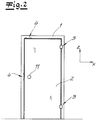
- the Fig. 1 shows a door arrangement with a door frame 1, a door leaf 2, two door hinges 3 and two magnetic locking devices 4.
- the door leaf 2 lies in a plane which is formed by a first horizontal direction X and the vertical Z.
- hinge side and hinge opposite side refer to the edges of the door leaf 2, which are spaced apart along the first horizontal direction X according to the width of the door leaf 2. Accordingly, the door hinges 3 are on the hinge side, while the two locking devices 4 are on the opposite hinge side. As will be explained in more detail below, the door leaf 2 slams over a door seal in the closed position (see below) 5a and 5b ) at a level 6 of the door frame 1.
- magnet arrangements 7 of the magnetic locking device 4 are inserted on the side of the door leaf 4 on the door frame 1 in side legs 8 extending outside the door leaf 2.
- the magnet arrangements 7 each have a multiplicity of magnets 9, a section 10 of magnetic material being arranged at the height of the magnet arrangement 7 on the door leaf 2.
- the section 10 can be designed as a sheet metal strip or sheet metal angle and extends approximately over the same height as the magnet arrangement 7.
- the door leaf 2 can simply be pushed on or pulled open.
- a handle opening 11 is shown in the door leaf 2 made of glass
- a fixed handle in the form of a knob or bracket can be arranged on at least one surface, preferably on both surfaces of the door leaf 2.
- the section 10 made of magnetic material, preferably as a sheet metal strip or sheet metal angle is formed, as well as a fixed handle can be glued to a door leaf 2 made of glass in a particularly simple manner.
- the Fig. 2 is intended to clarify that 4 different configurations come into consideration for the positioning of the locking device.
- the door arrangement can only have a single magnetic locking device 4, which is arranged, for example, at the level of the handle opening 11.
- an arrangement of the at least one magnetic locking device 4 on the opposite side of the hinge is preferred, another arrangement is also possible, for example in a lintel area above the door leaf 2, with a corresponding arrangement in the Fig. 2 is indicated by dash-dotted lines.
- the magnet arrangement 7 has a fastening plate 12 fastened to the door frame 1, in particular the side leg 8, and a carrier plate 13 which is adjustable relative to the fastening plate 12 and which carries the magnets 9.
- five circular cylindrical magnets 9 are arranged one above the other in a row along the vertical direction Z, it being possible to fall back on commercially available standard designs.
- the fastening plate 12 is rigidly fastened by screws 14 to the side leg 8 of the step 6 of the door frame 1, while the carrier plate 13 carrying the magnets 9 is adjustable along the first horizontal direction X by means of adjusting spindles 15 relative to the fastening plate 12 and thus the entire door arrangement.
- the magnets 9 By actuating the adjusting spindles 15 the magnets 9 thus move along the first horizontal direction X, it being possible for the gap remaining with the section 10 made of magnetic material when the door leaf 2 is closed to be enlarged and reduced. In this way, the closing forces of the magnetic locking device 4 can be adjusted.
- the fastening plate 12 has openings through which the magnets 9 are guided.
- the magnets 9 arranged one above the other have an alternating polarity.
- the magnets 9 are aligned along the first horizontal direction X and, when the door leaf 2 is closed, point in the direction of the then adjacent section 10 made of magnetic material.
- the fastening plate 12 is expediently formed from a non-magnetic metal.
- the carrier plate 13 is preferably formed from a magnetic material, in particular a ferromagnetic material, in order to form a type of magnetic yoke element. The closing forces can thereby be increased, and undesirable magnetic stray fields are also reduced.
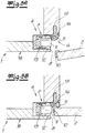
- the door frame 1 has the step 6 described above in order to form a stop for the door leaf 2.
- the step comprises a stop angle 16 on which the edge of the door leaf 2 rests via the door seal 5.
- the door seal 5 is held in a sealing groove 17 made in the stop bracket 16.
- the magnet arrangement 7 Since the magnet arrangement 7 is inserted into the side leg 8, it is barely perceptible to a user, especially when the door leaf 2 is closed. The same also applies to the section 10 made of magnetic material, which is also at least partially covered by the door seal 5 in the closed position of the door leaf 2.
- the stop leg 16 and the side leg 8 are arranged at right angles to one another on the step.
- the inconspicuous integration of the magnet arrangement 7 in the side leg 8 is also supported in that the magnet arrangement 7 in the exemplary embodiment shown is partially covered by the door seal 5 when the door leaf 2 is open.
- the door leaf 2 can be arranged in a simple manner flush with an end face 18 of the door frame 1 by a corresponding modification of the geometry.
Description
- Die Erfindung betrifft eine Türanordnung mit einer Türzarge, einem Türflügel, Türbändern und einer magnetischen Zuhalteeinrichtung, wobei die Türbänder an einer Bandseite des Türflügels befestigt sind und den Türflügel schwenkbar mit der Türzarge verbinden, wobei die Türzarge als Anschlag für den Türflügel in der Schließstellung eine Stufe aufweist, welche eine den Türflügel in der Schließstellung überdeckenden Anschlagschenkel und einen außerhalb des Türflügels verlaufenden Seitenschenkel aufweist und wobei die Zuhalteeinrichtung an der Türzarge eine Magnetanordnung sowie an einem Rand des Türflügels einen Abschnitt aus magnetischem Material umfasst.
- Aus dem Möbelreich sind Schranktüren sowie aus dem Sanitärbereich Duschtüren bekannt, welche durch magnetische Kräfte in einer Schließstellung gehalten werden. Es ergibt sich der Vorteil, dass eine solche Tür einerseits durch die Magnetkräfte sicher gehalten ist und andererseits leicht aufgedrückt werden kann, ohne dass eine Türfalle oder eine andere mechanische Verschlusseinrichtung betätigt werden muss.
- Bei den bekannten Türanordnungen umfasst die Zuhalteeinrichtung einen Magneten und einen Abschnitt aus metallischem Material. Der Magnet sowie der Abschnitt aus metallischem Material sind dabei so angeordnet, dass sich ein direkter mechanischer Kontakt ergibt. Bei Erreichen der Schließstellung schlägt die Magnetanordnung an dem magnetischen Material an, so dass sich ein metallisches Klack-Geräusch ergibt. Durch den direkten Kontakt kann bei einer langfristigen Benutzung auch eine Beschädigung nicht ausgeschlossen werden. Schließlich ist bei den bekannten Ausführungen die Kombination mit einer Türdichtung nicht ohne Weiteres möglich.
- Die vorliegende Erfindung beschäftigt sich konkret mit einer Türanordnung, welche bevorzugt eine Gebäudeinnentür bildet. Sämtliche Bestandteile der Türanordnung müssen also stabil genug sein, um eine den Durchtritt einer Person ermöglichende Fläche von zumindest 1m2 abzudecken, wobei das Gewicht des Türflügels üblicherweise zumindest 10 kg beträgt.
- Aus der
DE 20 2005 016 584 U1 ist eine magnetische Türschließvorrichtung bekannt, welche insbesondere für Vorrichtungen zur Lebensmittelverarbeitung vorgesehen ist. Zumindest ein Magnet ist an einer oberen Randfläche eines Türflügels vorgesehen und wirkt mit zumindest einem entgegengesetzt gepolten Magnet zusammen, der an einer unteren Randfläche eines Gehäuses angeordnet ist. Die beiden Teile der magnetischen Zuhalteeinrichtung sind somit im Wesentlichen gleich ausgebildet. - Auch gemäß der
DE 10 2004 054 028 A1 ist eine magnetische Zuhalteeinrichtung dadurch gebildet, dass an einer ersten Halteeinrichtung und einer zweiten Halteeinrichtung, die beispielsweise an einen Türflügel und einer Türzarge zugeordnet sein können, jeweils zumindest ein Magnet angeordnet ist, wobei die Magnete dann den Türflügel durch eine gegenseitige Wechselwirkung in eine gewünschten Position halten können. Zur Justage der gewünschten Position kann eine Verstellung vorgesehen sein. - Auch gemäß der
GB 1 009 996 - Gemäß einer bevorzugten Ausgestaltung der Erfindung ist der Türflügel aus Glas gebildet, wobei eine solche Glasscheibe im Vergleich zu anderen Gebäudeinnentüren eine relativ geringe Dicke aufweist. Anders als bei einer Tür aus Holz oder Röhrenspan können Beschlagteile wie die zuvor genannten Bänder, Schlösser oder dergleichen nicht in die dünne Glastür an dessen Rand eingesetzt werden.
- Gerade vor diesem Hintergrund besteht auch das Bedürfnis, eine möglichst einfache Zuhalteeinrichtung anzugeben, welche auch ein hochwertiges optisches Erscheinungsbild ermöglicht. Darüber hinaus müssen die Haltekräfte der Zuhalteeinrichtung auch ausreichend sein, um den Türflügel in seiner Schließposition zu halten.
- Vor diesem Hintergrund liegt der vorliegenden Erfindung die Aufgabe zugrunde, eine Türanordnung mit einer optisch unauffälligen Zuhalteeinrichtung anzugeben, welche sich gerade in Bezug auf Gebäudeinnentüren dennoch durch gute Gebrauchseigenschaften auszeichnet. Insbesondere soll die Zuhalteeinrichtung auch möglichst verschleiß- und wartungsfrei sein sowie in Kombination mit einer herkömmlichen Türdichtung eingesetzt werden können.
- Gegenstand der Erfindung und Lösung der Aufgabe ist eine Türanordnung gemäß Schutzanspruch 1.
- Ausgehend von der eingangs beschriebenen gattungsgemäßen Türanordnung ist demnach erfindungsgemäß vorgesehen, dass die Magnetanordnung an dem Seitenschenkel derart angeordnet ist, dass zwischen der Magnetanordnung und dem am Rand des Türflügels angeordneten Abschnitt aus magnetischem Material ein freier Spalt verbleibt. In der Schließstellung des Türflügels liegen sich die Magnetanordnung sowie der Abschnitt aus magnetischem Material unmittelbar gegenüber ohne sich jedoch direkt zu berühren. Durch den geringen Abstand von typischerweise zwischen 0,5 mm und 10 mm können dabei Haltekräfte erzeugt werden, welche den Türflügel ausreichend sicher in der Schließposition halten.
- Die Magnetanordnung ist dabei bei einer Ansicht des geschlossenen Türflügels außerhalb des Türflügels im Bereich des Außenumfangs angeordnet.
- Üblicherweise befindet sich die Magnetanordnung an der Bandgegenseite, an der bei herkömmlichen Gebäudeinnentüren auch das Türschloss angeordnet ist. Grundsätzlich sind im Rahmen der Erfindung jedoch auch andere Anordnungen möglich. Beispielsweise kann die Zuhalteeinrichtung mit der Magnetanordnung in dem Sturzbereich der Türzarge und mit dem Abschnitt aus magnetischem Material an dem oberen Rand des Türflügels angeordnet sein.
- Wenn gemäß einer bevorzugten Ausgestaltung der Erfindung die Zuhalteeinrichtung an der Bandgegenseite des Türflügels angeordnet ist, so kann eine einzige Zuhalteeinrichtung vorgesehen sein, welche sich dann bevorzugt in einer mittleren Höhe des Türflügels befindet. Insbesondere befindet sich die Zuhalteeinrichtung dann in einem mittleren Drittel des Türflügels. Alternativ können auch zwei oder mehr Zuhalteeinrichtungen vorhanden sein, um insgesamt die Zuhaltekräfte zu erhöhen. Bei einer Ausgestaltung mit zwei Zuhalteeinrichtungen befindet sich eine erste Zuhalteeinrichtung beispielsweise an der Bandgegenseite in einem unteren Bereich des Türflügels, während eine zweite Zuhalteeinrichtung sich an der Bandgegenseite in einem oberen Bereich des Türflügels befindet.
- Der Türflügel ist einer gemäß bevorzugten Ausgestaltung aus Glas gebildet, wobei gerade bei einer solchen Glastür eine möglichst unauffällige und wenig sichtbare Zuhalteeinrichtung von Vorteil ist. Insbesondere kann auch vollständig auf ein Türschloss mit einer Falle verzichtet werden.
- An dem Türflügel selbst ist nur der Abschnitt aus magnetischem Material anzubringen, wobei es sich um einen einfachen Blechstreifen oder auch einen Blechwinkel handelt. Ein solcher Blechstreifen oder Blechwinkel kann auf besonders einfache Weise auf den seitlichen Rand des Türflügels an dessen Bandgegenseite aufgeklebt werden und ist dann bei einer Benutzung der Türanordnung kaum sichtbar.
- Die Magnetanordnung ist dagegen an der Türzarge vorgesehen und an der den Anschlag für den Türflügel bildenden Stufe an dem Seitenschenkel angeordnet. Besonders bevorzugt ist die Magnetanordnung an dem Seitenschenkel in die Türzarge eingesetzt und somit in besonders vorteilhafter Weise verdeckt angeordnet.
- In Bezug auf die übliche Ausrichtung einer Türanordnung liegt der Türflügel in der Schließstellung in einer Ebene, welche von der Vertikalen sowie einer ersten horizontalen Richtung definiert wird. Die erste horizontale Richtung erstreckt sich dann entlang der Breite des Türflügels. Ausgehend von einem rechtwinkligen Koordinatensystem entspricht dann die die Dickenrichtung des Türflügels einer zweiten horizontalen Richtung.
- Die den Anschlag bildende Stufe weist den Anschlagschenkel auf, der parallel zu dem Türflügel in der Schließstellung ausgerichtet ist und demnach entlang der Vertikalen und der ersten horizontalen Richtung verläuft. Der Seitenschenkel verläuft rechtwinklig dazu an der Bandseite des Türflügels sowie an der Bandgegenseite des Türflügels in vertikaler Richtung sowie entlang der zweiten horizontalen Richtung, also in Dickenrichtung. In dem Sturzbereich erstreckt sich der Seitenschenkel ebenfalls entlang der zweiten horizontalen Richtung und oberhalb des Türflügels entlang der ersten horizontalen Richtung. Bezogen auf die gesamte Türzarge bildet also der Seitenschenkel eine um den äußeren Rand des Türflügels umlaufende Einfassung.
- Üblicherweise ist die beschriebene Stufe als Anschlag an der Bandseite, der Bandgegenseite sowie im Sturzbereich vorhanden. Grundsätzlich sind aber auch Ausgestaltungen denkbar, bei denen sich der Anschlag nicht in der beschriebenen Weise um den Türflügel herum erstreckt. Die Stufe ist aber zumindest an der Bandgegenseite oder im Sturzbereich vorhanden, um die magnetische Zuhalteeinrichtung dort anordnen zu können.
- Erfindungsgemäß muss der Türflügel nicht mit einer mechanisch betätigten Klinke und einer Türfalle ausgerüstet werden. Es ist deshalb ausreichend, wenn der vorzugsweise aus Glas gebildete Türflügel an seiner Bandgegenseite lediglich eine Grifföffnung, eine Grifföse oder einen anders ausgestalteten feststehenden Griff aufweist. Ein solcher feststehender Griff erstreckt sich vorzugsweise an beiden Flächen des Türflügels, um diesen leicht aufziehen bzw. aufdrücken zu können. Ein Aufdrücken des geschlossenen Türflügels in seiner Öffnungsrichtung ist jedoch grundsätzlich auch ohne einen feststehenden Griff möglich.
- Der feststehende Griff kann ohne Weiteres als Knauf oder Bügel ausgeführt sein.
- Gemäß einer bevorzugten Ausgestaltung der Erfindung weist die Magnetanordnung eine Vielzahl von Magneten auf, die bevorzugt in einer Reihe angeordnet sind. Bei der üblichen Ausrichtung des Türflügels können beispielsweise mehrere Magneten in einer Reihe entlang der vertikalen Richtung übereinander angeordnet sein, so dass auch bei geringen Tiefe des Seitenschenkels entlang der zweiten horizontalen Richtung, also in Dickenrichtung, ausreichende Magnetkräfte bereitgestellt werden können. Dabei ist zu berücksichtigen, dass gerade bei einer verdeckten Anordnung auch eine entlang der vertikalen Richtung relativ ausgedehnte Magnetanordnung nicht oder kaum als störend wahrgenommen wird.
- Bei dem zumindest einen Magnet der Magnetanordnung sind die Pole mit ihrer Flächennormale zweckmäßigerweise in Richtung des in Schließstellung angrenzenden Randes des Türflügels mit dem daran angeordneten magnetischen Material ausgerichtet. Wenn die Magnetanordnung also an der Bandgegenseite (bei einer klassischen Tür also der Schlossseite) angeordnet ist, verläuft die Normale der Magnetpole dann entlang der ersten horizontalen Richtung.
- Wenn gemäß der zuvor als bevorzugt dargestellten Ausgestaltung mehrere Magnete in einer Reihe angeordnet sind, so weisen diese zweckmäßigerweise eine sich abwechselnde Polausrichtung auf. Wenn bei einer solchen Anordnung dann in der Schließstellung des Türflügels das magnetische Material sich in unmittelbarer Nähe der Magnetanordnung befindet, verlaufen die Feldlinien durch dieses magnetische Material von einem Magnet direkt zu dem entgegengesetzt gepolten benachbarten Magnet, wodurch sich besonders hohe Haltekräfte und geringe Streufelder ergeben. Auch im Hinblick auf einen geöffneten Türflügel ergibt sich bei einer abwechselnden Polausrichtung der Vorteil einer geringeren Reichweite des Magnetfeldes, so dass magnetisch empfindliche Gegenstände eines Benutzers wie beispielsweise Kredit- und Magnetkarten weniger stark gefährdet sind.
- Sofern im Rahmen der Erfindung eine Vielzahl von Magneten vorgesehen ist, so können diese beispielsweise eine Zylinderform, insbesondere eine Kreiszylinderform aufweisen, wobei dann die Pole entlang der Zylinderachse ausgerichtet sind. Es ergibt sich im Rahmen einer solchen Ausgestaltung der Vorteil, dass auf kostengünstige, handelsübliche Standardmagnete zurückgegriffen werden kann. Da im Rahmen der Erfindung der Abschnitt aus magnetischem Material nicht an der Magnetanordnung, also den Magneten anschlägt, ergibt sich kein Verschleiß und auch keine Gefahr einer Beschädigung der Magnete.
- Gemäß einer bevorzugten Weiterbildung der Erfindung ist vorgesehen, dass die Magnetanordnung einen Verstellmechanismus aufweist, mit welchem der Abstand zwischen dem Magnet bzw. den Magneten der Magnetanordnung und dem Abschnitt aus magnetischem Material einstellbar ist. Wenn die zumindest eine magnetische Zuhalteeinrichtung also an der Bandgegenseite angeordnet ist, so ist die Magnetanordnung zweckmäßigerweise entlang der ersten horizontalen Richtung verstellbar. Durch eine solche Verstellung kann der zwischen dem Abschnitt aus magnetischem Material sowie der Magnetanordnung verbleibende freie Spalt variiert werden, wodurch auch die Haltekräfte genau eingestellt werden können.
- Für die konkrete Ausgestaltung der Magnetanordnung ergeben sich im Rahmen der Erfindung verschiedene Ausgestaltungsmöglichkeiten. Um die beschriebene Verstellbarkeit zu ermöglichen, kann die Magnetanordnung beispielsweise eine an der Türzarge befestigte Befestigungsplatte und eine gegenüber der Befestigungsplatte verstellbare Trägerplatte aufweisen, welche den zumindest einen Magneten trägt.
- Bei einer Ausgestaltung mit einer Vielzahl von Magneten kann die Trägerplatte auch aus einem magnetischen Material gebildet sein und gerade auch bei einer bevorzugten wechselweisen Polausrichtung eine Art Jochelement bilden, wodurch die magnetischen Kräfte weiter erhöht und Streufelder reduziert werden.
- Die an der Türzarge befestigte Befestigungsplatte ist vorzugsweise aus einem nicht-magnetischen Material, insbesondere nicht-magnetischen Metall gebildet, um eine klemmfreie Bewegung des Magneten bzw. der Magnete zu ermöglichen und um eine Reduzierung der magnetischen Haltekräfte zu vermeiden. Insbesondere kann die Befestigungsplatte Öffnungen aufweisen, durch welche die eine Zylinderform aufweisenden Magnete durchgeführt sind.
- Eine Verstellung der die Magnete tragenden Trägerplatte gegenüber der Befestigungsplatte ist beispielsweise durch zwei Stellspindeln als Verstellmechanismus möglich.
- Da die Magnetanordnung an dem Seitenschenkel an dem Außenumfang des Türflügels angeordnet ist, kann der Türflügel auch auf besonders vorteilhafte Weise gegen eine Türdichtung anschlagen, die an der Stufe der Türzarge angeordnet ist. Insbesondere kann die Türdichtung in einer in den Anschlagwinkel eingebrachten Dichtungsnut gehalten sein.
- Ohne Weiteres kann die Türdichtung die Magnetanordnung bei einem geöffneten Türflügel zumindest teilweise verdecken, wodurch diese weiter optisch kaschiert wird.
- Wenn die Magnetanordnung in geeigneter Weise gegenüber einer solchen Türdichtung ausgerichtet ist, kann auch im geschlossenen Zustand des Türflügels eine gewünschte Komprimierung der Türrichtung erreicht werden. Wenn der Türflügel mit großer Kraft zugeschlagen wird, kann diese Bewegung dann von der Türdichtung abgefedert werden, während die Zuhalteeinrichtung dann ein Aufspringen des Türflügels verhindern kann.
- Auch wenn dies für viele Anwendungsfälle nicht notwendig ist, kommt grundsätzlich auch eine Verstellbarkeit der Magnetanordnung entlang der zweiten horizontalen Richtung, also entlang der Dickenrichtung des Türflügels in Betracht, um den Andruck des Türflügels an die Türdichtung variieren zu können.
- Die Magnetanordnung sowie der zugeordnete Abschnitt aus magnetischem Material erstrecken sich üblicherweise über eine in etwa gleiche Länge, also bei der üblichen Anordnung an der Bandgegenseite über einen in etwa gleiche Höhe entlang der vertikalen Richtung.
- Die Länge der Magnetanordnung sowie des Abschnittes aus magnetischem Material kann beispielsweise zwischen 5 und 20 cm betragen.
- Durch die magnetische Zuhalteeinrichtung wird keine öffnungssichere Verriegelung gewährleistet. Die Türanordnung ist vor diesem Hintergrund vorzugsweise für Gebäudeinnentüren vorgesehen, welche nicht mit einem Schlüssel verschlossen werden sollen. Alternativ ist aber auch eine separate Verriegelung durch einen Riegel, Bügel oder dergleichen möglich.
- Die Erfindung wird nachfolgend anhand von lediglich exemplarischen Zeichnungen erläutert. Es zeigen:
- Fig. 1
- eine Türanordnung mit einem geschlossenen Türflügel und zwei magnetischen Zuhalteeinrichtungen an einer Bandgegenseite des Türflügels,
- Fig. 2
- die Türanordnung gemäß der
Fig. 1 mit lediglich einer magnetischen Zuhalteeinrichtung an alternativen Positionen, - Fig. 3
- eine an einer Türzarge der Türanordnung montierte Magnetanordnung der magnetischen Zuhalteeinrichtung,
- Fig. 4
- der in
Fig. 3 dargestellte Abschnitt der Türanordnung in einer teilgeschnittenen und um 90° gedrehten Ansicht, - Fig. 5a
- ein Horizontalschnitt durch die Türanordnung im geöffneten Zustand,
- Fig.5b
- ein Horizontalschnitt durch die Türanordnung bei einem geschlossenen Türflügel.
- Die
Fig. 1 zeigt eine Türanordnung mit einer Türzarge 1, einem Türflügel 2, zwei Türbändern 3 sowie zwei magnetischen Zuhalteeinrichtungen 4. Der Türflügel 2 liegt in dem dargestellten geschlossenen Zustand in einer Ebene, welche von einer ersten horizontalen Richtung X und der Vertikalen Z gebildet ist. - Im Rahmen der Erfindung beziehen sich die Begriffe Bandseite und Bandgegenseite auf die Ränder des Türflügels 2, welche entlang der ersten horizontalen Richtung X gemäß der Breite des Türflügels 2 voneinander beabstandet sind. Demnach befinden sich die Türbänder 3 an der Bandseite, während sich die beiden Zuhalteeinrichtungen 4 an der Bandgegenseite befinden. Wie nachfolgend noch weiter erläutert wird, schlägt der Türflügel 2 in der Schließstellung über eine Türdichtung (siehe nachfolgend zu
Fig. 5a und 5b ) an einer Stufe 6 der Türzarge 1 an. - Wie nachfolgend noch weiter erläutert, sind Magnetanordnungen 7 der magnetischen Zuhalteeinrichtung 4 seitlich des Türflügels 4 an der Türzarge 1 in außerhalb des Türflügels 2 verlaufenden Seitenschenkel 8 eingesetzt. Die Magnetanordnungen 7 weisen jeweils eine Vielzahl von Magneten 9 auf, wobei auf der Höhe der Magnetanordnung 7 an dem Türflügel 2 ein Abschnitt 10 aus magnetischem Material angeordnet ist. Der Abschnitt 10 kann als Blechstreifen oder Blechwinkel ausgeführt sein und erstreckt sich in etwa über die gleiche Höhe wie die Magnetanordnung 7.
- Bereits in der
Fig. 1 ist zu erkennen, dass bei jeder magnetischen Zuhalteeinrichtung 4 zwischen der Magnetanordnung 7 und dem Abschnitt aus magnetischem Material 10 entlang der ersten horizontalen Richtung ein freier Spalt verbleibt, so dass der Abschnitt 10 aus magnetischem Material nicht an den Magneten 9 anschlägt. Entsprechend werden bei der erfindungsgemäßen Schließfunktion sowohl eine Geräuschentwicklung als auch ein Verschleiß bzw. eine Abnutzung sicher vermieden. - Aufgrund der magnetischen Zuhalteeinrichtung 4 ist für die dargestellte Türanordnung in Form einer Gebäudeinnentür kein Schloss mit einem Schlosskasten und einer Schließfalle notwendig.
- In Öffnungsrichtung kann der Türflügel 2 einfach aufgedrückt bzw. aufgezogen werden. Hierzu ist in der
Fig. 1 exemplarisch eine Grifföffnung 11 in dem Türflügel 2 aus Glas dargestellt, wobei alternativ an zumindest einer Fläche vorzugsweise an beiden Flächen des Türflügels 2 ein feststehender Griff in Form eines Knaufs oder Bügels angeordnet werden kann. Der Abschnitt 10 aus magnetischem Material, der vorzugsweise als Blechstreifen oder Blechwinkel ausgebildet ist, sowie ein feststehender Griff können bei einem Türflügel 2 aus Glas auf besonders einfache Weise aufgeklebt werden. - Die
Fig. 2 soll verdeutlichen, dass für die Positionierung der Zuhalteeinrichtung 4 unterschiedliche Ausgestaltungen in Betracht kommen. Insbesondere kann die Türanordnung lediglich eine einzige magnetische Zuhalteeinrichtung 4 aufweisen, die beispielsweise auf Höhe der Grifföffnung 11 angeordnet ist. Obwohl eine Anordnung der zumindest einen magnetischen Zuhalteeinrichtung 4 an der Bandgegenseite bevorzugt ist, ist auch eine andere Anordnung, beispielsweise in einem Sturzbereich oberhalb des Türflügels 2 möglich, wobei eine entsprechende Anordnung in derFig. 2 strichpunktiert angedeutet ist. - Weitere Details der Magnetanordnung 7 als Bestandteil der magnetischen Zuhalteeinrichtung 4 ergeben sich aus den
Fig. 3 und4 . Aus einer vergleichenden Betrachtung derFig. 3 sowie derFig. 4 ist ersichtlich, dass die Magnetanordnung eine an der Türzarge 1, insbesondere dem Seitenschenkel 8 befestigte Befestigungsplatte 12 sowie eine gegenüber der Befestigungsplatte 12 verstellbare Trägerplatte 13 aufweist, welche die Magnete 9 trägt. - In dem dargestellten Ausführungsbeispiel sind exemplarisch fünf kreiszylindrische Magnete 9 in einer Reihe entlang der vertikalen Richtung Z übereinander angeordnet, wobei auf handelsüblich verfügbare Standardausführungen zurückgegriffen werden kann.
- Die Befestigungsplatte 12 ist durch Schrauben 14 starr an dem Seitenschenkel 8 der Stufe 6 der Türzarge 1 befestigt, während die die Magnete 9 tragende Trägerplatte 13 mittels Stellspindeln 15 gegenüber der Befestigungsplatte 12 und somit der gesamten Türanordnung entlang der ersten horizontalen Richtung X verstellbar ist. Durch eine Betätigung der Stellspindeln 15 werden die Magnete 9 also entlang der ersten horizontalen Richtung X bewegt, wobei der bei einem geschlossenen Türflügel 2 zu dem Abschnitt 10 aus magnetischem Material verbleibende Spalt vergrößert und verkleinert werden kann. Auf diese Weise können die Schließkräfte der magnetischen Zuhalteeinrichtung 4 eingestellt werden.
- In den
Fig. 3 und4 ist auch zu erkennen, dass die Befestigungsplatte 12 Öffnungen aufweist, durch welche die Magnete 9 geführt sind. - Die konkrete Bauform der Magnetanordnung 7 sowie die Ausgestaltung der Verstellung ist rein exemplarisch.
- Gemäß der
Fig. 4 weisen die übereinander angeordneten Magnete 9 eine sich abwechselnde Polarität auf. Die Magnete 9 sind entlang der ersten horizontalen Richtung X ausgerichtet und weisen bei einem geschlossenen Türflügel 2 in Richtung des dann angrenzenden Abschnittes 10 aus magnetischem Material. - Um eine leichte Bewegung der Magnete 9 zu ermöglichen und eine Beeinträchtigung der Schließkräfte zu verhindern, ist die Befestigungsplatte 12 zweckmäßigerweise aus einem nicht-magnetischen Metall gebildet. Die Trägerplatte 13 ist dagegen vorzugsweise aus einem magnetischen Material, insbesondere einem ferromagnetischen Material gebildet, um eine Art magnetisches Jochelement zu bilden. Die Schließkräfte können dadurch erhöht werden, wobei auch unerwünschte magnetische Streufelder reduziert werden.
- In der
Fig. 4 sind einzelne Magnetfeldlinien zur Verdeutlichung exemplarisch dargestellt, wobei der Türflügel 2 geöffnet ist und somit die Feldlinien an der Vorderseite der Magnetanordnung 7 austreten können. Durch die wechselweise Polarisierung der Magnete 9 wird aber auch dabei eine große Reichweite der Magnetkräfte, welche für einen Benutzer von Nachteil sein kann, verhindert. - Die Anordnung der zumindest einen magnetischen Zuhalteeinrichtung 4 an der Türanordnung ist in den
Fig. 5a und 5b besonders deutlich dargestellt. Demnach weist die Türzarge 1 die zuvor beschriebene Stufe 6 auf, um einen Anschlag für den Türflügel 2 zu bilden. Die Stufe umfasst dabei einen Anschlagwinkel 16 auf dem der Rand des Türflügels 2 über die Türdichtung 5 anliegt. Die Türdichtung 5 ist dazu in einer in dem Anschlagwinkel 16 eingebrachten Dichtungsnut 17 gehalten. - In der
Fig. 5b , welche den Türflügel 2 in seiner Schließstellung zeigt, ist der freie Spalt zwischen den Magneten 9 der Magnetanordnung 7 einerseits und dem als Blechwinkel ausgestalteten Abschnitt 10 aus magnetischem Material zu erkennen. - Da die Magnetanordnung 7 in den Seitenschenkel 8 eingesetzt ist, ist diese für einen Benutzer kaum wahrnehmbar, insbesondere wenn der Türflügel 2 geschlossen ist. Das gleiche gilt auch für den Abschnitt 10 aus magnetischem Material, der in der Schließstellung des Türflügels 2 auch zumindest teilweise von der Türdichtung 5 abgedeckt wird.
- Gemäß dem Horizontalschnitt der
Fig. 5a und 5b entlang der ersten horizontalen Richtung X sowie der zweiten horizontalen Richtung Y sind der Anschlagschenkel 16 sowie der Seitenschenkel 8 an der Stufe rechtwinklig zueinander angeordnet. Die unauffällige Integration der Magnetanordnung 7 in dem Seitenschenkel 8 wird auch dadurch unterstützt, dass die Magnetanordnung 7 in dem dargestellten Ausführungsbeispiel teilweise von der Türdichtung 5 verdeckt ist, wenn der Türflügel 2 geöffnet ist. - Aus den
Fig. 5a und 5b ist auch ersichtlich, dass der Türflügel 2 auf einfache Weise flächenbündig mit einer Stirnseite 18 der Türzarge 1 durch eine entsprechende Modifikation der Geometrie angeordnet werden kann.
Claims (17)
- Türanordnung mit einer Türzarge (1), einem Türflügel (2), Türbändern (3) und einer magnetischen Zuhalteeinrichtung (4), wobei die Türbänder (2) an einer Bandseite des Türflügels (2) befestigt sind und den Türflügel (2) schwenkbar mit der Türzarge (1) verbinden, wobei die Türzarge (1) als Anschlag für den Türflügel (2) in der Schließstellung eine Stufe (6) aufweist, welche einen den Türflügel (2) in der Schließstellung überdeckenden, entlang der Vertikalen und entlang einer ersten horizontalen Richtung verlaufenden Anschlagschenkel (16) und einen außerhalb des Türflügels (2) entlang der Vertikalen und einer zweiten horizontalen Richtung verlaufenden Seitenschenkel (8) aufweist, wobei die Zuhalteeinrichtung (4) an der Türzarge (1) eine Magnetanordnung (7) sowie an einem Rand des Türflügels (2) einen Abschnitt (10) aus magnetischem Material umfasst, wobei die Magnetanordnung (7) an dem Seitenschenkel (8) derart angeordnet ist, dass zwischen der Magnetanordnung (7) und dem am Rand des Türflügels (2) angeordneten Abschnitt (10) aus magnetischem Material ein freier Spalt verbleibt, wobei der Abschnitt (10) aus magnetischem Material von einem Blechstreifen oder Blechwinkel gebildet ist.
- Türanordnung nach Anspruch 1, wobei der Türflügel (2) aus Glas gebildet ist.
- Türanordnung nach Anspruch 1 oder 2, wobei der Türflügel (2) an einer Bandgegenseite eine Grifföffnung (11) oder einen feststehenden Griff aufweist.
- Türanordnung nach einem der Ansprüche 1 bis 3, wobei genau eine Zuhalteeinrichtung (4) vorgesehen ist, welche in einer mittleren Höhe des Türflügels (2) angeordnet ist.
- Türanordnung nach einem der Ansprüche 1 bis 4, wobei die Magnetanordnung (7) eine Vielzahl von in einer Reihe angeordneten Magneten (9) aufweist.
- Türanordnung nach Anspruch 5, wobei die Magnete (9) eine sich abwechselnde Polausrichtung aufweisen.
- Türanordnung nach Anspruch 5 oder 6, wobei die Magnete (9) eine Zylinderform aufweisen.
- Türanordnung nach einem der Ansprüche 1 bis 7, wobei die Magnetanordnung (7) einen Verstellmechanismus aufweist, mit welchem der Abstand zwischen zumindest einem Magnet (9) der Magnetanordnung (7) und dem Abschnitt (10) aus magnetischem Material einstellbar ist.
- Türanordnung nach Anspruch 8, wobei die Magnetanordnung (7) eine an der Türzarge (1) befestigte Befestigungsplatte (12) und eine gegenüber der Befestigungsplatte (12) verstellbare Trägerplatte (13) aufweist, welche den zumindest einen Magneten (9) trägt.
- Türanordnung nach Anspruch 7 und Anspruch 9, wobei die Befestigungsplatte (12) Öffnungen aufweist, durch welche Magnete (9) mit einer Zylinderform durchgeführt sind.
- Türanordnung nach Anspruch 9 oder 10, wobei die Trägerplatte (13) mit zwei Stellspindeln (15) gegenüber der Befestigungsplatte (12) verstellbar ist.
- Türanordnung nach einem der Ansprüche 9 bis 11, wobei die Befestigungsplatte (12) aus einem nicht-magnetischen Material, insbesondere einem nicht-magnetischen Metall, gebildet ist.
- Türanordnung nach einem der Ansprüche 9 bis 12, wobei die Trägerplatte (13) aus magnetischem Material gebildet ist.
- Türanordnung nach einem der Ansprüche 1 bis 13, wobei an der Stufe (6) der Türzarge (1) eine Türdichtung (5) angeordnet ist.
- Türanordnung nach Anspruch 14, wobei die Türdichtung (5) in einer in den Anschlagschenkel (16) eingebrachten Dichtungsnut (17) gehalten ist.
- Türanordnung nach Anspruch 14 oder 15, wobei die Türdichtung (5) die Magnetanordnung (7) bei einem geöffneten Türflügel (2) zumindest teilweise verdeckt.
- Türanordnung nach einem der Ansprüche 1 bis 16, wobei diese eine Gebäudeinnentür, insbesondere Zimmertür bildet.
Priority Applications (1)
| Application Number | Priority Date | Filing Date | Title |
|---|---|---|---|
| PL17207836T PL3348759T3 (pl) | 2017-01-12 | 2017-12-15 | Układ drzwi |
Applications Claiming Priority (1)
| Application Number | Priority Date | Filing Date | Title |
|---|---|---|---|
| DE202017100143.1U DE202017100143U1 (de) | 2017-01-12 | 2017-01-12 | Türanordnung |
Publications (2)
| Publication Number | Publication Date |
|---|---|
| EP3348759A1 EP3348759A1 (de) | 2018-07-18 |
| EP3348759B1 true EP3348759B1 (de) | 2020-06-03 |
Family
ID=58160794
Family Applications (1)
| Application Number | Title | Priority Date | Filing Date |
|---|---|---|---|
| EP17207836.2A Active EP3348759B1 (de) | 2017-01-12 | 2017-12-15 | Türanordnung |
Country Status (6)
| Country | Link |
|---|---|
| US (1) | US10689889B2 (de) |
| EP (1) | EP3348759B1 (de) |
| CN (1) | CN108301713B (de) |
| DE (1) | DE202017100143U1 (de) |
| PL (1) | PL3348759T3 (de) |
| RU (1) | RU2694918C2 (de) |
Families Citing this family (9)
| Publication number | Priority date | Publication date | Assignee | Title |
|---|---|---|---|---|
| FR3070708A1 (fr) * | 2017-09-01 | 2019-03-08 | Bamo | Porte interieure d'un logement comprenant un systeme de fermeture magnetique passif |
| DE102018001278A1 (de) | 2018-02-17 | 2019-08-22 | Markus Wolf | Magnetisches Türendschließsystem |
| CZ2018427A3 (cs) * | 2018-08-23 | 2019-10-30 | Material & Technology S.R.O. | Zajišťovací prostředek |
| DE202018107134U1 (de) | 2018-12-13 | 2019-01-02 | Simonswerk Gmbh | Magnetische Türzuhalteeinrichtung und damit ausgestattete Türanordnung |
| DE102019100388B3 (de) | 2019-01-09 | 2020-06-18 | Joh. Sprinz Gmbh & Co. Kg | Türvorrichtung mit flächenbündiger Abschlussebene sowie Wandsystem |
| DE102019100637A1 (de) * | 2019-01-11 | 2020-07-16 | Simonswerk Gmbh | Magnetschloss sowie Tür |
| DE202019001416U1 (de) | 2019-03-13 | 2020-06-15 | Markus Wolf | Erweitertertes magnetisches Tür(end)schließsystem |
| DE102020115423A1 (de) | 2020-06-10 | 2021-12-16 | DSC Door Solution Company GmbH | Vorrichtung zum Zuhalten einer Tür |
| DE102020122730B3 (de) | 2020-08-31 | 2021-05-12 | Simonswerk Gmbh | Gebäudetür und Türband für eine Gebäudetür |
Family Cites Families (25)
| Publication number | Priority date | Publication date | Assignee | Title |
|---|---|---|---|---|
| US2557568A (en) * | 1945-04-21 | 1951-06-19 | Lewis M Sanders | Plate-glass door construction |
| US2984510A (en) * | 1957-01-08 | 1961-05-16 | Otto H Hoffmann | Quiet door lock |
| DE1199158B (de) * | 1961-08-21 | 1965-08-19 | Licentia Gmbh | Magnetverschluss, insbesondere fuer Kuehlschraenke |
| DE3041572A1 (de) * | 1980-11-04 | 1982-06-09 | Leo 8260 Mühldorf Schörghuber | Tuerschliesser |
| US4826223A (en) * | 1985-02-19 | 1989-05-02 | Geringer Arthur V | Electromagnetic door lock device |
| US4840411A (en) * | 1987-02-13 | 1989-06-20 | Harrow Products, Inc. | Electromagnetic shear lock |
| GB2254644B (en) * | 1991-04-12 | 1994-04-27 | Technophone Ltd | Magnetic catch |
| AU2002218779A1 (en) * | 2000-07-10 | 2002-01-21 | Endura Products, Inc. | Threshold assembly with pre-fitted draining jamb boots and pre-fitted mull boots |
| DE10050111C1 (de) * | 2000-10-09 | 2002-08-08 | Dorma Gmbh & Co Kg | Verriegelungsvorrichtung |
| RU2229009C2 (ru) * | 2001-10-10 | 2004-05-20 | Сугробов Анатолий Михайлович | Магнитомеханический замок (варианты) |
| JP3823068B2 (ja) * | 2002-05-24 | 2006-09-20 | 株式会社ユニフロー | 扉支持具 |
| DE20219171U1 (de) * | 2002-12-11 | 2003-04-10 | Havranek Ladislav | Glastüre mit Magnetmechanismus und Trennwandsystem mit Glastüre |
| US6722715B1 (en) * | 2003-03-31 | 2004-04-20 | Fanny Chiang | Magnetic swing door lock |
| CN2649729Y (zh) * | 2003-11-18 | 2004-10-20 | 谢伯年 | 磁性固定装置 |
| DE102004054028A1 (de) * | 2004-11-05 | 2006-05-11 | KL-Beschläge Karl Loggen GmbH | Vorrichtung zum Positionieren einer Tür |
| US7567159B2 (en) * | 2005-02-03 | 2009-07-28 | Macken John A | Energy absorbing magnetic coupling device |
| DE202005016584U1 (de) * | 2005-10-13 | 2006-01-12 | Miwe Michael Wenz Gmbh | Magnetische Türschließvorrichtung |
| US7770947B2 (en) * | 2008-03-19 | 2010-08-10 | Soca Technology Co., Ltd. | Electromagnetic lock |
| NZ568456A (en) * | 2008-05-20 | 2010-10-29 | Roderick Nigel Redgrave | Closure mechanism with two magnetic assemblies that are offset in alignment when the door is closed |
| US20120043768A1 (en) * | 2010-08-17 | 2012-02-23 | Thomas Graham | Magnetic latch assembly |
| JP5462132B2 (ja) * | 2010-11-10 | 2014-04-02 | Ykk Ap株式会社 | 建具 |
| US10450776B2 (en) * | 2013-04-05 | 2019-10-22 | Rutherford Controls Int'l Inc. | Low power magnetic lock assembly |
| CN204002309U (zh) * | 2013-12-25 | 2014-12-10 | 浙江金辰玻璃有限公司 | 一种玻璃门 |
| US9879461B2 (en) * | 2015-03-04 | 2018-01-30 | Bobrick Washroom Equipment, Inc. | Partition and closing system for partition |
| CN107636243A (zh) * | 2015-05-22 | 2018-01-26 | 应用材料公司 | 包括磁性门密封件的基板载体门组件、基板载体和方法 |
-
2017
- 2017-01-12 DE DE202017100143.1U patent/DE202017100143U1/de active Active
- 2017-12-15 PL PL17207836T patent/PL3348759T3/pl unknown
- 2017-12-15 EP EP17207836.2A patent/EP3348759B1/de active Active
-
2018
- 2018-01-10 US US15/866,692 patent/US10689889B2/en active Active
- 2018-01-11 RU RU2018100450A patent/RU2694918C2/ru active
- 2018-01-12 CN CN201810029477.0A patent/CN108301713B/zh not_active Expired - Fee Related
Also Published As
| Publication number | Publication date |
|---|---|
| US20180195327A1 (en) | 2018-07-12 |
| CN108301713B (zh) | 2021-12-17 |
| RU2018100450A (ru) | 2019-07-11 |
| DE202017100143U1 (de) | 2017-02-06 |
| RU2018100450A3 (de) | 2019-07-17 |
| EP3348759A1 (de) | 2018-07-18 |
| US10689889B2 (en) | 2020-06-23 |
| PL3348759T3 (pl) | 2020-11-16 |
| CN108301713A (zh) | 2018-07-20 |
| RU2694918C2 (ru) | 2019-07-18 |
Similar Documents
| Publication | Publication Date | Title |
|---|---|---|
| EP3348759B1 (de) | Türanordnung | |
| EP2093358A1 (de) | Vorrichtung zum Feststellen von Türen mittels magnestischer Anziehung | |
| DE102007014324A1 (de) | Türschließsystem mit einem ebenen Schließblech | |
| EP2255051B1 (de) | Schloss | |
| EP2685032B1 (de) | Elektronische schliesseinheit für den schrank einer mehrfach-schliessanlage | |
| EP1520953B1 (de) | Vorsatztür oder -fenster, insbesondere Insektenschutztür oder -fenster | |
| EP3680426A1 (de) | Magnetschloss sowie tür | |
| EP2543797B1 (de) | Türöffnereinrichtung mit Permanentmagnet | |
| EP2754790B1 (de) | Element mit selbstzentrierendem Beschlag für Fenster oder Türen | |
| DE102019100639B3 (de) | Türbedienanordnung sowie Tür | |
| DE202008009389U1 (de) | Türeinheit | |
| EP3752697A1 (de) | Magnetischer türendschliesser und verfahren dazu | |
| DE202015005011U1 (de) | Glanzglastür | |
| DE102009019731B4 (de) | Schließeinrichtung | |
| DE10236707B4 (de) | Vorrichtung für eine Tür | |
| EP2740867B1 (de) | Schliessteil für treibstangenbeschlag | |
| AT520324B1 (de) | Metallzarge | |
| DE19943195A1 (de) | Fenster, Tür o. dgl. sowie Rahmenprofil hierfür | |
| EP3647529B1 (de) | Auslöser für eine türdichtung mit anhebbarer und absenkbarer dichtungsleiste | |
| EP4001574A1 (de) | Gebäudetür und türband für eine gebäudetür | |
| EP1498563B1 (de) | Spaltlüftungsvorrichtung | |
| DE102008032072A1 (de) | Schließblech und Stulp und deren Verwendung | |
| DE4445383C1 (de) | Schließplatte | |
| EP3816375A1 (de) | Bauteilsystem für einen riegeleingriff | |
| DE3538239C2 (de) |
Legal Events
| Date | Code | Title | Description |
|---|---|---|---|
| PUAI | Public reference made under article 153(3) epc to a published international application that has entered the european phase |
Free format text: ORIGINAL CODE: 0009012 |
|
| STAA | Information on the status of an ep patent application or granted ep patent |
Free format text: STATUS: THE APPLICATION HAS BEEN PUBLISHED |
|
| STAA | Information on the status of an ep patent application or granted ep patent |
Free format text: STATUS: REQUEST FOR EXAMINATION WAS MADE |
|
| AK | Designated contracting states |
Kind code of ref document: A1 Designated state(s): AL AT BE BG CH CY CZ DE DK EE ES FI FR GB GR HR HU IE IS IT LI LT LU LV MC MK MT NL NO PL PT RO RS SE SI SK SM TR |
|
| AX | Request for extension of the european patent |
Extension state: BA ME |
|
| 17P | Request for examination filed |
Effective date: 20180627 |
|
| RBV | Designated contracting states (corrected) |
Designated state(s): AL AT BE BG CH CY CZ DE DK EE ES FI FR GB GR HR HU IE IS IT LI LT LU LV MC MK MT NL NO PL PT RO RS SE SI SK SM TR |
|
| GRAP | Despatch of communication of intention to grant a patent |
Free format text: ORIGINAL CODE: EPIDOSNIGR1 |
|
| STAA | Information on the status of an ep patent application or granted ep patent |
Free format text: STATUS: GRANT OF PATENT IS INTENDED |
|
| RIC1 | Information provided on ipc code assigned before grant |
Ipc: E05C 19/16 20060101AFI20191220BHEP Ipc: E05B 65/00 20060101ALI20191220BHEP Ipc: E05B 63/00 20060101ALN20191220BHEP Ipc: A47K 3/30 20060101ALI20191220BHEP |
|
| INTG | Intention to grant announced |
Effective date: 20200120 |
|
| GRAS | Grant fee paid |
Free format text: ORIGINAL CODE: EPIDOSNIGR3 |
|
| GRAA | (expected) grant |
Free format text: ORIGINAL CODE: 0009210 |
|
| STAA | Information on the status of an ep patent application or granted ep patent |
Free format text: STATUS: THE PATENT HAS BEEN GRANTED |
|
| AK | Designated contracting states |
Kind code of ref document: B1 Designated state(s): AL AT BE BG CH CY CZ DE DK EE ES FI FR GB GR HR HU IE IS IT LI LT LU LV MC MK MT NL NO PL PT RO RS SE SI SK SM TR |
|
| REG | Reference to a national code |
Ref country code: GB Ref legal event code: FG4D Free format text: NOT ENGLISH |
|
| REG | Reference to a national code |
Ref country code: CH Ref legal event code: EP Ref country code: AT Ref legal event code: REF Ref document number: 1277179 Country of ref document: AT Kind code of ref document: T Effective date: 20200615 |
|
| REG | Reference to a national code |
Ref country code: DE Ref legal event code: R096 Ref document number: 502017005537 Country of ref document: DE |
|
| REG | Reference to a national code |
Ref country code: NL Ref legal event code: FP |
|
| REG | Reference to a national code |
Ref country code: CH Ref legal event code: NV Representative=s name: KELLER AND PARTNER PATENTANWAELTE AG, CH |
|
| REG | Reference to a national code |
Ref country code: CH Ref legal event code: PFA Owner name: SIMONSWERK GMBH, DE Free format text: FORMER OWNER: SIMONSWERK GMBH, DE |
|
| REG | Reference to a national code |
Ref country code: LT Ref legal event code: MG4D |
|
| PG25 | Lapsed in a contracting state [announced via postgrant information from national office to epo] |
Ref country code: LT Free format text: LAPSE BECAUSE OF FAILURE TO SUBMIT A TRANSLATION OF THE DESCRIPTION OR TO PAY THE FEE WITHIN THE PRESCRIBED TIME-LIMIT Effective date: 20200603 Ref country code: GR Free format text: LAPSE BECAUSE OF FAILURE TO SUBMIT A TRANSLATION OF THE DESCRIPTION OR TO PAY THE FEE WITHIN THE PRESCRIBED TIME-LIMIT Effective date: 20200904 Ref country code: NO Free format text: LAPSE BECAUSE OF FAILURE TO SUBMIT A TRANSLATION OF THE DESCRIPTION OR TO PAY THE FEE WITHIN THE PRESCRIBED TIME-LIMIT Effective date: 20200903 Ref country code: SE Free format text: LAPSE BECAUSE OF FAILURE TO SUBMIT A TRANSLATION OF THE DESCRIPTION OR TO PAY THE FEE WITHIN THE PRESCRIBED TIME-LIMIT Effective date: 20200603 Ref country code: FI Free format text: LAPSE BECAUSE OF FAILURE TO SUBMIT A TRANSLATION OF THE DESCRIPTION OR TO PAY THE FEE WITHIN THE PRESCRIBED TIME-LIMIT Effective date: 20200603 |
|
| PG25 | Lapsed in a contracting state [announced via postgrant information from national office to epo] |
Ref country code: HR Free format text: LAPSE BECAUSE OF FAILURE TO SUBMIT A TRANSLATION OF THE DESCRIPTION OR TO PAY THE FEE WITHIN THE PRESCRIBED TIME-LIMIT Effective date: 20200603 Ref country code: RS Free format text: LAPSE BECAUSE OF FAILURE TO SUBMIT A TRANSLATION OF THE DESCRIPTION OR TO PAY THE FEE WITHIN THE PRESCRIBED TIME-LIMIT Effective date: 20200603 Ref country code: LV Free format text: LAPSE BECAUSE OF FAILURE TO SUBMIT A TRANSLATION OF THE DESCRIPTION OR TO PAY THE FEE WITHIN THE PRESCRIBED TIME-LIMIT Effective date: 20200603 Ref country code: BG Free format text: LAPSE BECAUSE OF FAILURE TO SUBMIT A TRANSLATION OF THE DESCRIPTION OR TO PAY THE FEE WITHIN THE PRESCRIBED TIME-LIMIT Effective date: 20200903 |
|
| PG25 | Lapsed in a contracting state [announced via postgrant information from national office to epo] |
Ref country code: AL Free format text: LAPSE BECAUSE OF FAILURE TO SUBMIT A TRANSLATION OF THE DESCRIPTION OR TO PAY THE FEE WITHIN THE PRESCRIBED TIME-LIMIT Effective date: 20200603 |
|
| PG25 | Lapsed in a contracting state [announced via postgrant information from national office to epo] |
Ref country code: PT Free format text: LAPSE BECAUSE OF FAILURE TO SUBMIT A TRANSLATION OF THE DESCRIPTION OR TO PAY THE FEE WITHIN THE PRESCRIBED TIME-LIMIT Effective date: 20201006 Ref country code: EE Free format text: LAPSE BECAUSE OF FAILURE TO SUBMIT A TRANSLATION OF THE DESCRIPTION OR TO PAY THE FEE WITHIN THE PRESCRIBED TIME-LIMIT Effective date: 20200603 Ref country code: SM Free format text: LAPSE BECAUSE OF FAILURE TO SUBMIT A TRANSLATION OF THE DESCRIPTION OR TO PAY THE FEE WITHIN THE PRESCRIBED TIME-LIMIT Effective date: 20200603 Ref country code: RO Free format text: LAPSE BECAUSE OF FAILURE TO SUBMIT A TRANSLATION OF THE DESCRIPTION OR TO PAY THE FEE WITHIN THE PRESCRIBED TIME-LIMIT Effective date: 20200603 Ref country code: ES Free format text: LAPSE BECAUSE OF FAILURE TO SUBMIT A TRANSLATION OF THE DESCRIPTION OR TO PAY THE FEE WITHIN THE PRESCRIBED TIME-LIMIT Effective date: 20200603 |
|
| PG25 | Lapsed in a contracting state [announced via postgrant information from national office to epo] |
Ref country code: SK Free format text: LAPSE BECAUSE OF FAILURE TO SUBMIT A TRANSLATION OF THE DESCRIPTION OR TO PAY THE FEE WITHIN THE PRESCRIBED TIME-LIMIT Effective date: 20200603 Ref country code: IS Free format text: LAPSE BECAUSE OF FAILURE TO SUBMIT A TRANSLATION OF THE DESCRIPTION OR TO PAY THE FEE WITHIN THE PRESCRIBED TIME-LIMIT Effective date: 20201003 |
|
| REG | Reference to a national code |
Ref country code: DE Ref legal event code: R097 Ref document number: 502017005537 Country of ref document: DE |
|
| PLBE | No opposition filed within time limit |
Free format text: ORIGINAL CODE: 0009261 |
|
| STAA | Information on the status of an ep patent application or granted ep patent |
Free format text: STATUS: NO OPPOSITION FILED WITHIN TIME LIMIT |
|
| PG25 | Lapsed in a contracting state [announced via postgrant information from national office to epo] |
Ref country code: DK Free format text: LAPSE BECAUSE OF FAILURE TO SUBMIT A TRANSLATION OF THE DESCRIPTION OR TO PAY THE FEE WITHIN THE PRESCRIBED TIME-LIMIT Effective date: 20200603 |
|
| 26N | No opposition filed |
Effective date: 20210304 |
|
| PG25 | Lapsed in a contracting state [announced via postgrant information from national office to epo] |
Ref country code: SI Free format text: LAPSE BECAUSE OF FAILURE TO SUBMIT A TRANSLATION OF THE DESCRIPTION OR TO PAY THE FEE WITHIN THE PRESCRIBED TIME-LIMIT Effective date: 20200603 |
|
| PGFP | Annual fee paid to national office [announced via postgrant information from national office to epo] |
Ref country code: TR Payment date: 20201215 Year of fee payment: 4 |
|
| PG25 | Lapsed in a contracting state [announced via postgrant information from national office to epo] |
Ref country code: MC Free format text: LAPSE BECAUSE OF FAILURE TO SUBMIT A TRANSLATION OF THE DESCRIPTION OR TO PAY THE FEE WITHIN THE PRESCRIBED TIME-LIMIT Effective date: 20200603 |
|
| PG25 | Lapsed in a contracting state [announced via postgrant information from national office to epo] |
Ref country code: IE Free format text: LAPSE BECAUSE OF NON-PAYMENT OF DUE FEES Effective date: 20201215 Ref country code: LU Free format text: LAPSE BECAUSE OF NON-PAYMENT OF DUE FEES Effective date: 20201215 |
|
| PG25 | Lapsed in a contracting state [announced via postgrant information from national office to epo] |
Ref country code: MT Free format text: LAPSE BECAUSE OF FAILURE TO SUBMIT A TRANSLATION OF THE DESCRIPTION OR TO PAY THE FEE WITHIN THE PRESCRIBED TIME-LIMIT Effective date: 20200603 Ref country code: CY Free format text: LAPSE BECAUSE OF FAILURE TO SUBMIT A TRANSLATION OF THE DESCRIPTION OR TO PAY THE FEE WITHIN THE PRESCRIBED TIME-LIMIT Effective date: 20200603 |
|
| PG25 | Lapsed in a contracting state [announced via postgrant information from national office to epo] |
Ref country code: MK Free format text: LAPSE BECAUSE OF FAILURE TO SUBMIT A TRANSLATION OF THE DESCRIPTION OR TO PAY THE FEE WITHIN THE PRESCRIBED TIME-LIMIT Effective date: 20200603 |
|
| PGFP | Annual fee paid to national office [announced via postgrant information from national office to epo] |
Ref country code: PL Payment date: 20221202 Year of fee payment: 6 |
|
| PGFP | Annual fee paid to national office [announced via postgrant information from national office to epo] |
Ref country code: CH Payment date: 20230103 Year of fee payment: 6 |
|
| PGFP | Annual fee paid to national office [announced via postgrant information from national office to epo] |
Ref country code: GB Payment date: 20231220 Year of fee payment: 7 |
|
| PGFP | Annual fee paid to national office [announced via postgrant information from national office to epo] |
Ref country code: NL Payment date: 20231220 Year of fee payment: 7 Ref country code: IT Payment date: 20231228 Year of fee payment: 7 Ref country code: FR Payment date: 20231222 Year of fee payment: 7 Ref country code: DE Payment date: 20231201 Year of fee payment: 7 Ref country code: CZ Payment date: 20231211 Year of fee payment: 7 Ref country code: AT Payment date: 20231221 Year of fee payment: 7 |
|
| PGFP | Annual fee paid to national office [announced via postgrant information from national office to epo] |
Ref country code: BE Payment date: 20231220 Year of fee payment: 7 |
|
| PGFP | Annual fee paid to national office [announced via postgrant information from national office to epo] |
Ref country code: CH Payment date: 20240102 Year of fee payment: 7 |