EP3337720B1 - Elektrofahrrad - Google Patents
Elektrofahrrad Download PDFInfo
- Publication number
- EP3337720B1 EP3337720B1 EP16757869.9A EP16757869A EP3337720B1 EP 3337720 B1 EP3337720 B1 EP 3337720B1 EP 16757869 A EP16757869 A EP 16757869A EP 3337720 B1 EP3337720 B1 EP 3337720B1
- Authority
- EP
- European Patent Office
- Prior art keywords
- electric bicycle
- control unit
- bicycle according
- remote control
- selection buttons
- Prior art date
- Legal status (The legal status is an assumption and is not a legal conclusion. Google has not performed a legal analysis and makes no representation as to the accuracy of the status listed.)
- Active
Links
Images


Classifications
-
- B—PERFORMING OPERATIONS; TRANSPORTING
- B62—LAND VEHICLES FOR TRAVELLING OTHERWISE THAN ON RAILS
- B62M—RIDER PROPULSION OF WHEELED VEHICLES OR SLEDGES; POWERED PROPULSION OF SLEDGES OR SINGLE-TRACK CYCLES; TRANSMISSIONS SPECIALLY ADAPTED FOR SUCH VEHICLES
- B62M6/00—Rider propulsion of wheeled vehicles with additional source of power, e.g. combustion engine or electric motor
- B62M6/40—Rider propelled cycles with auxiliary electric motor
- B62M6/55—Rider propelled cycles with auxiliary electric motor power-driven at crank shafts parts
-
- B—PERFORMING OPERATIONS; TRANSPORTING
- B62—LAND VEHICLES FOR TRAVELLING OTHERWISE THAN ON RAILS
- B62K—CYCLES; CYCLE FRAMES; CYCLE STEERING DEVICES; RIDER-OPERATED TERMINAL CONTROLS SPECIALLY ADAPTED FOR CYCLES; CYCLE AXLE SUSPENSIONS; CYCLE SIDECARS, FORECARS, OR THE LIKE
- B62K11/00—Motorcycles, engine-assisted cycles or motor scooters with one or two wheels
- B62K11/14—Handlebar constructions, or arrangements of controls thereon, specially adapted thereto
-
- B—PERFORMING OPERATIONS; TRANSPORTING
- B60—VEHICLES IN GENERAL
- B60K—ARRANGEMENT OR MOUNTING OF PROPULSION UNITS OR OF TRANSMISSIONS IN VEHICLES; ARRANGEMENT OR MOUNTING OF PLURAL DIVERSE PRIME-MOVERS IN VEHICLES; AUXILIARY DRIVES FOR VEHICLES; INSTRUMENTATION OR DASHBOARDS FOR VEHICLES; ARRANGEMENTS IN CONNECTION WITH COOLING, AIR INTAKE, GAS EXHAUST OR FUEL SUPPLY OF PROPULSION UNITS IN VEHICLES
- B60K35/00—Instruments specially adapted for vehicles; Arrangement of instruments in or on vehicles
- B60K35/10—Input arrangements, i.e. from user to vehicle, associated with vehicle functions or specially adapted therefor
-
- B—PERFORMING OPERATIONS; TRANSPORTING
- B60—VEHICLES IN GENERAL
- B60K—ARRANGEMENT OR MOUNTING OF PROPULSION UNITS OR OF TRANSMISSIONS IN VEHICLES; ARRANGEMENT OR MOUNTING OF PLURAL DIVERSE PRIME-MOVERS IN VEHICLES; AUXILIARY DRIVES FOR VEHICLES; INSTRUMENTATION OR DASHBOARDS FOR VEHICLES; ARRANGEMENTS IN CONNECTION WITH COOLING, AIR INTAKE, GAS EXHAUST OR FUEL SUPPLY OF PROPULSION UNITS IN VEHICLES
- B60K35/00—Instruments specially adapted for vehicles; Arrangement of instruments in or on vehicles
- B60K35/20—Output arrangements, i.e. from vehicle to user, associated with vehicle functions or specially adapted therefor
- B60K35/21—Output arrangements, i.e. from vehicle to user, associated with vehicle functions or specially adapted therefor using visual output, e.g. blinking lights or matrix displays
- B60K35/22—Display screens
-
- B—PERFORMING OPERATIONS; TRANSPORTING
- B60—VEHICLES IN GENERAL
- B60K—ARRANGEMENT OR MOUNTING OF PROPULSION UNITS OR OF TRANSMISSIONS IN VEHICLES; ARRANGEMENT OR MOUNTING OF PLURAL DIVERSE PRIME-MOVERS IN VEHICLES; AUXILIARY DRIVES FOR VEHICLES; INSTRUMENTATION OR DASHBOARDS FOR VEHICLES; ARRANGEMENTS IN CONNECTION WITH COOLING, AIR INTAKE, GAS EXHAUST OR FUEL SUPPLY OF PROPULSION UNITS IN VEHICLES
- B60K35/00—Instruments specially adapted for vehicles; Arrangement of instruments in or on vehicles
- B60K35/60—Instruments characterised by their location or relative disposition in or on vehicles
-
- B—PERFORMING OPERATIONS; TRANSPORTING
- B62—LAND VEHICLES FOR TRAVELLING OTHERWISE THAN ON RAILS
- B62J—CYCLE SADDLES OR SEATS; AUXILIARY DEVICES OR ACCESSORIES SPECIALLY ADAPTED TO CYCLES AND NOT OTHERWISE PROVIDED FOR, e.g. ARTICLE CARRIERS OR CYCLE PROTECTORS
- B62J11/00—Supporting arrangements specially adapted for fastening specific devices to cycles, e.g. supports for attaching maps
-
- B—PERFORMING OPERATIONS; TRANSPORTING
- B62—LAND VEHICLES FOR TRAVELLING OTHERWISE THAN ON RAILS
- B62J—CYCLE SADDLES OR SEATS; AUXILIARY DEVICES OR ACCESSORIES SPECIALLY ADAPTED TO CYCLES AND NOT OTHERWISE PROVIDED FOR, e.g. ARTICLE CARRIERS OR CYCLE PROTECTORS
- B62J43/00—Arrangements of batteries
- B62J43/30—Arrangements of batteries for providing power to equipment other than for propulsion
-
- B—PERFORMING OPERATIONS; TRANSPORTING
- B62—LAND VEHICLES FOR TRAVELLING OTHERWISE THAN ON RAILS
- B62J—CYCLE SADDLES OR SEATS; AUXILIARY DEVICES OR ACCESSORIES SPECIALLY ADAPTED TO CYCLES AND NOT OTHERWISE PROVIDED FOR, e.g. ARTICLE CARRIERS OR CYCLE PROTECTORS
- B62J50/00—Arrangements specially adapted for use on cycles not provided for in main groups B62J1/00 - B62J45/00
- B62J50/20—Information-providing devices
- B62J50/21—Information-providing devices intended to provide information to rider or passenger
- B62J50/22—Information-providing devices intended to provide information to rider or passenger electronic, e.g. displays
-
- B—PERFORMING OPERATIONS; TRANSPORTING
- B62—LAND VEHICLES FOR TRAVELLING OTHERWISE THAN ON RAILS
- B62J—CYCLE SADDLES OR SEATS; AUXILIARY DEVICES OR ACCESSORIES SPECIALLY ADAPTED TO CYCLES AND NOT OTHERWISE PROVIDED FOR, e.g. ARTICLE CARRIERS OR CYCLE PROTECTORS
- B62J6/00—Arrangement of optical signalling or lighting devices on cycles; Mounting or supporting thereof; Circuits therefor
- B62J6/16—Arrangement of switches
-
- B—PERFORMING OPERATIONS; TRANSPORTING
- B62—LAND VEHICLES FOR TRAVELLING OTHERWISE THAN ON RAILS
- B62K—CYCLES; CYCLE FRAMES; CYCLE STEERING DEVICES; RIDER-OPERATED TERMINAL CONTROLS SPECIALLY ADAPTED FOR CYCLES; CYCLE AXLE SUSPENSIONS; CYCLE SIDECARS, FORECARS, OR THE LIKE
- B62K17/00—Cycles not otherwise provided for
-
- B—PERFORMING OPERATIONS; TRANSPORTING
- B62—LAND VEHICLES FOR TRAVELLING OTHERWISE THAN ON RAILS
- B62K—CYCLES; CYCLE FRAMES; CYCLE STEERING DEVICES; RIDER-OPERATED TERMINAL CONTROLS SPECIALLY ADAPTED FOR CYCLES; CYCLE AXLE SUSPENSIONS; CYCLE SIDECARS, FORECARS, OR THE LIKE
- B62K19/00—Cycle frames
- B62K19/30—Frame parts shaped to receive other cycle parts or accessories
-
- B—PERFORMING OPERATIONS; TRANSPORTING
- B62—LAND VEHICLES FOR TRAVELLING OTHERWISE THAN ON RAILS
- B62K—CYCLES; CYCLE FRAMES; CYCLE STEERING DEVICES; RIDER-OPERATED TERMINAL CONTROLS SPECIALLY ADAPTED FOR CYCLES; CYCLE AXLE SUSPENSIONS; CYCLE SIDECARS, FORECARS, OR THE LIKE
- B62K19/00—Cycle frames
- B62K19/30—Frame parts shaped to receive other cycle parts or accessories
- B62K19/40—Frame parts shaped to receive other cycle parts or accessories for attaching accessories, e.g. article carriers, lamps
-
- B—PERFORMING OPERATIONS; TRANSPORTING
- B62—LAND VEHICLES FOR TRAVELLING OTHERWISE THAN ON RAILS
- B62K—CYCLES; CYCLE FRAMES; CYCLE STEERING DEVICES; RIDER-OPERATED TERMINAL CONTROLS SPECIALLY ADAPTED FOR CYCLES; CYCLE AXLE SUSPENSIONS; CYCLE SIDECARS, FORECARS, OR THE LIKE
- B62K23/00—Rider-operated controls specially adapted for cycles, i.e. means for initiating control operations, e.g. levers, grips
- B62K23/02—Rider-operated controls specially adapted for cycles, i.e. means for initiating control operations, e.g. levers, grips hand actuated
-
- B—PERFORMING OPERATIONS; TRANSPORTING
- B62—LAND VEHICLES FOR TRAVELLING OTHERWISE THAN ON RAILS
- B62K—CYCLES; CYCLE FRAMES; CYCLE STEERING DEVICES; RIDER-OPERATED TERMINAL CONTROLS SPECIALLY ADAPTED FOR CYCLES; CYCLE AXLE SUSPENSIONS; CYCLE SIDECARS, FORECARS, OR THE LIKE
- B62K23/00—Rider-operated controls specially adapted for cycles, i.e. means for initiating control operations, e.g. levers, grips
- B62K23/02—Rider-operated controls specially adapted for cycles, i.e. means for initiating control operations, e.g. levers, grips hand actuated
- B62K23/06—Levers
-
- B—PERFORMING OPERATIONS; TRANSPORTING
- B62—LAND VEHICLES FOR TRAVELLING OTHERWISE THAN ON RAILS
- B62M—RIDER PROPULSION OF WHEELED VEHICLES OR SLEDGES; POWERED PROPULSION OF SLEDGES OR SINGLE-TRACK CYCLES; TRANSMISSIONS SPECIALLY ADAPTED FOR SUCH VEHICLES
- B62M25/00—Actuators for gearing speed-change mechanisms specially adapted for cycles
- B62M25/08—Actuators for gearing speed-change mechanisms specially adapted for cycles with electrical or fluid transmitting systems
-
- B—PERFORMING OPERATIONS; TRANSPORTING
- B62—LAND VEHICLES FOR TRAVELLING OTHERWISE THAN ON RAILS
- B62M—RIDER PROPULSION OF WHEELED VEHICLES OR SLEDGES; POWERED PROPULSION OF SLEDGES OR SINGLE-TRACK CYCLES; TRANSMISSIONS SPECIALLY ADAPTED FOR SUCH VEHICLES
- B62M6/00—Rider propulsion of wheeled vehicles with additional source of power, e.g. combustion engine or electric motor
- B62M6/40—Rider propelled cycles with auxiliary electric motor
- B62M6/45—Control or actuating devices therefor
-
- B—PERFORMING OPERATIONS; TRANSPORTING
- B62—LAND VEHICLES FOR TRAVELLING OTHERWISE THAN ON RAILS
- B62M—RIDER PROPULSION OF WHEELED VEHICLES OR SLEDGES; POWERED PROPULSION OF SLEDGES OR SINGLE-TRACK CYCLES; TRANSMISSIONS SPECIALLY ADAPTED FOR SUCH VEHICLES
- B62M6/00—Rider propulsion of wheeled vehicles with additional source of power, e.g. combustion engine or electric motor
- B62M6/40—Rider propelled cycles with auxiliary electric motor
- B62M6/45—Control or actuating devices therefor
- B62M6/50—Control or actuating devices therefor characterised by detectors or sensors, or arrangement thereof
-
- G—PHYSICS
- G06—COMPUTING OR CALCULATING; COUNTING
- G06F—ELECTRIC DIGITAL DATA PROCESSING
- G06F3/00—Input arrangements for transferring data to be processed into a form capable of being handled by the computer; Output arrangements for transferring data from processing unit to output unit, e.g. interface arrangements
- G06F3/01—Input arrangements or combined input and output arrangements for interaction between user and computer
- G06F3/02—Input arrangements using manually operated switches, e.g. using keyboards or dials
-
- B—PERFORMING OPERATIONS; TRANSPORTING
- B62—LAND VEHICLES FOR TRAVELLING OTHERWISE THAN ON RAILS
- B62J—CYCLE SADDLES OR SEATS; AUXILIARY DEVICES OR ACCESSORIES SPECIALLY ADAPTED TO CYCLES AND NOT OTHERWISE PROVIDED FOR, e.g. ARTICLE CARRIERS OR CYCLE PROTECTORS
- B62J50/00—Arrangements specially adapted for use on cycles not provided for in main groups B62J1/00 - B62J45/00
- B62J50/20—Information-providing devices
- B62J50/21—Information-providing devices intended to provide information to rider or passenger
- B62J50/225—Mounting arrangements therefor
-
- B—PERFORMING OPERATIONS; TRANSPORTING
- B62—LAND VEHICLES FOR TRAVELLING OTHERWISE THAN ON RAILS
- B62K—CYCLES; CYCLE FRAMES; CYCLE STEERING DEVICES; RIDER-OPERATED TERMINAL CONTROLS SPECIALLY ADAPTED FOR CYCLES; CYCLE AXLE SUSPENSIONS; CYCLE SIDECARS, FORECARS, OR THE LIKE
- B62K21/00—Steering devices
- B62K21/12—Handlebars; Handlebar stems
-
- B—PERFORMING OPERATIONS; TRANSPORTING
- B62—LAND VEHICLES FOR TRAVELLING OTHERWISE THAN ON RAILS
- B62K—CYCLES; CYCLE FRAMES; CYCLE STEERING DEVICES; RIDER-OPERATED TERMINAL CONTROLS SPECIALLY ADAPTED FOR CYCLES; CYCLE AXLE SUSPENSIONS; CYCLE SIDECARS, FORECARS, OR THE LIKE
- B62K2204/00—Adaptations for driving cycles by electric motor
-
- B—PERFORMING OPERATIONS; TRANSPORTING
- B62—LAND VEHICLES FOR TRAVELLING OTHERWISE THAN ON RAILS
- B62M—RIDER PROPULSION OF WHEELED VEHICLES OR SLEDGES; POWERED PROPULSION OF SLEDGES OR SINGLE-TRACK CYCLES; TRANSMISSIONS SPECIALLY ADAPTED FOR SUCH VEHICLES
- B62M25/00—Actuators for gearing speed-change mechanisms specially adapted for cycles
- B62M2025/003—Actuators for gearing speed-change mechanisms specially adapted for cycles with gear indicating means, e.g. a display
Definitions
- the present invention relates to an electric bicycle according to the preamble of claim 1.
- Electric bicycles such as pedelecs or e-bikes, are very popular as easy-to-use, emission-free means of transport.
- Electric bicycles offer the possibility of increasing the radius of use and increasing the average driving speed without overstraining the rider.
- Electric bicycles are known from the state of the art which, in addition to a drive unit and a battery unit, also have a display unit and a remote control unit for the display unit.
- the remote control unit is arranged in the area of a handlebar grip away from the display unit and is provided with support selection buttons for selecting the support level of the electric drive.
- the remote control unit also has an input device for menu navigation. and selection of menu items shown on the display unit.
- the disadvantage of such remote control units is that the frequently used support selection buttons and the input device are arranged next to each other and therefore cannot be operated ergonomically by the driver's thumb. The driver often has to reach around to operate the input device, which is a safety-critical issue.
- Such display units and remote control units are used in the US 2012/049483 A1 and the US 6 204 752 B1 described. Document US 6 204 752 B1 discloses the preamble of claim 1.
- the invention is therefore based on the object of providing a novel electric bicycle which brings electrically assisted mobility into line with the demands of sporty and lifestyle-oriented cyclists.
- An electric bicycle according to the invention with a remote control unit for the display unit of the electric bicycle is arranged in the area of a handlebar grip away from the display unit and has support selection buttons for selecting the support level, a rocker switch for gear selection and at least one input device for menu navigation and selection of menu items shown on the display unit.
- the input device, support selection buttons and rocker switch viewed in the direction of the handlebar grip axis, the input device, support selection buttons and rocker switch preferably run along a convex, curved common line, the curvature of which is ergonomically adapted to the range of motion of the driver's thumb.
- the input device and the keys are preferably arranged one below the other in such a way that that they can be operated ergonomically with the driver's thumb. The driver does not need to change his grip, which is critical for safety, to operate the support selection buttons and input device.
- the input device is designed as a joystick. Menu navigation and selection of menu items shown on the display unit can thus be carried out intuitively and ergonomically, preferably with the driver's thumb.
- the joystick can preferably be moved in all four directions (up and down; left and right), with menu items being selected by pressing the joystick (press function). Menu navigation and menu item selection are carried out using the multifunctional joystick, so that no other control elements are required.
- the remote control unit is therefore extremely compact and aesthetically pleasing.
- the joystick can have a backlit symbol, in particular a rectangle with rounded corners.
- the support selection buttons are arranged at an angle to one another.
- the selection of the support level can be carried out ergonomically with the driver's thumb.
- the support selection buttons preferably form a concave section. The thumb can rest between the buttons arranged one above the other so that operation is intuitive, with the support selection button for increasing the support level preferably being arranged at the front in the direction of travel and the support selection button for reducing the support level being arranged at the rear in the direction of travel.
- the support selection buttons are arranged at an angle towards the driver's hand.
- the operation can be carried out ergonomically preferably with the driver's thumb.
- the support selection button for increasing the support level is preferably marked with a plus symbol and the support selection button for decreasing the support level is preferably marked with a minus symbol.
- the symbols are preferably backlit and can therefore be seen even in poor visibility conditions.
- a light switch is arranged offset laterally in the area between the support selection buttons.
- the light switch is preferably arranged next to the support selection buttons in a direction away from the driver's hand. It has proven to be particularly ergonomic if the light switch is arranged offset laterally in the middle between the support selection buttons.
- the light switch preferably has three functions, which are activated sequentially by pressing a button: hold down the button (>2s) lights on/off; press the button to switch on the low beam, press the button a second time to switch on the high beam. It is therefore advantageous to have one button for light on/low/high/off.
- the light switch can have a backlit light symbol.
- the remote control unit preferably has a rocker switch for selecting gears, which is mounted centrally along a pivot axis.
- the rocker switch has two actuating surfaces, with a first actuating surface being arranged on a side facing the driver's hand and a second actuating surface being arranged on a side facing away from the driver's hand.
- the input device, support selection buttons and rocker switch are preferably arranged along a common line.
- the buttons are preferably arranged one below the other in such a way that they can be operated ergonomically with the driver's thumb. The driver does not need to reach around in order to operate the support selection buttons, input device and rocker switch, which is critical for safety.
- the remote control unit has an upper part and a modular, replaceable lower part, with the rocker switch being assigned to the lower part.
- the remote control unit can therefore be adapted in a modular manner to bicycles with and without electric motor transmissions.
- a lower part designed as a clamp half is optionally mounted with or without a rocker switch.
- a fastening section of the upper part and the lower part preferably each surrounds half of the handlebar.
- the upper part and lower part are preferably connected electrically by means of a flexible band.
- the shift paddle preferably has an automatic button positioned approximately in the middle.
- the automatic button preferably does not move and activates the automatic gear selection. For example, the first or second gear of the engine transmission.
- the input device Viewed in the direction of the handlebar grip axis, the input device, support selection buttons and shift rocker preferably run along a convex, curved common line, the curvature of which is ergonomically adapted to the range of motion of the driver's thumb.
- the remote control unit preferably has a vibration motor.
- a short vibration can be used to signal that the highest level of support has been reached.
- a gear change can also be suggested using a short vibration.
- a gear suggestion is preferably shown on the display unit, e.g. an arrow pointing up on the display as a suggestion to change up, with the vibration alerting the driver that the display unit is showing new information.
- an electronic control unit In a particularly preferred embodiment of the invention, an electronic control unit, a drive unit and a battery unit are also provided. It has proven particularly advantageous if the electronic control unit is located in the seat tube of the bicycle frame. This achieves a highly integrated interaction between the frame and the built-in elements.
- the design of the battery unit which is arranged in the down tube of the bicycle frame in particular, is not restricted and there is more space available for the battery cells and thus a long range. Due to the thermal decoupling of the battery unit and the electronic control unit, a high level of efficiency is achieved. Special battery housings with a mounting option for the control unit are not required. Overall, this variant achieves a compact, homogeneous frame shape of the highest strength.
- the inventive concept therefore also meets the requirements of a lifestyle-oriented, sporty rider.
- the electric bike therefore has an optimized frame cross-section with the best structural and aesthetic properties and optimized installation space requirements.
- the electronic control unit is attached to the frame-side drive bracket (motor bracket) of the drive unit. This means that no further fastening elements are required. A weight reduction can be achieved.
- the electronic control unit is preferably provided with cable connections only at one end section facing the drive unit, so that the structure is simplified and the cable lengths are minimal. All cables are preferably led out at the bottom of the frame.
- At least one stop, in particular a fastening element of the bottle holder, for example a bottle holder bushing, for the seat post is arranged above the electronic control unit. This prevents the electronic control unit from being damaged by a long seat post.
- At least one signal line of the remote control unit is connected to the display unit and at least one electrical line of the display unit is connected to the electronic control unit. It has proven to be particularly advantageous if only one bus line is provided between the remote control unit and the display unit. Furthermore, it is particularly advantageous if only one bus line is provided between the display unit and the electronic control unit. The number of lines to be laid and thus the weight and assembly effort are therefore minimized.
- the brake signal lines are connected directly to the display unit. This means that only one electrical line is required between the electronic control unit and the display unit. The number of lines is reduced. The brake light is activated when the brake is applied.
- the remote control unit is connected to the display unit with a single bus cable containing several signal lines.
- sensor lines are each connected directly to the electronic control unit.
- the number of lines is also reduced.
- side stand sensor safety deactivation when the stand is folded down
- gear sensor gear sensor
- acceleration sensors (3D gyro and accelerometer)
- sensor for detecting bicycle folding on folding bikes pressure sensors and temperature sensors.
- Communication preferably takes place using the CAN bus method, particularly preferably the CAN open method.
- a CAN translator is provided if adaptation is required.
- the invention can be implemented universally on all types of bicycles, especially mountain bikes (both in hardtail and full suspension design), but also on other bicycles, e.g. road bike frames, and thus ultimately results in a touring, city or cross bike or other modern types of bicycle. Due to the compact, elegant design, it enables the construction of bicycles that largely combine the advantages of a classic bicycle and an electric bicycle.
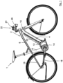
- Figure 1 shows a side view of an electric bicycle 1 according to the invention with a bicycle frame 2 designed as a diamond frame with a down tube 4, a top tube 6, a seat tube 8, a head tube 10, a drive carrier 12 for a drive unit 14 as well as seat stays 16 and lower stays 18 as well as a battery unit 20.
- a bicycle frame 2 designed as a diamond frame with a down tube 4, a top tube 6, a seat tube 8, a head tube 10, a drive carrier 12 for a drive unit 14 as well as seat stays 16 and lower stays 18 as well as a battery unit 20.
- FIG. 2 which shows a detailed view of the electric bicycle 1 from Figure 1 in the area of the bicycle handlebar 22 in the area of the bicycle handlebar 22
- a display unit 24 arranged centrally on the handlebar 22 and a remote control unit 26 are provided.
- the remote control unit 26 is arranged in the area of a left handlebar grip 28 away from the display unit 24 and has two support selection buttons 30, 32 for selecting the motor support level and an input device designed as a joystick 34 for menu navigation and selection of menu items shown on the display unit 24.
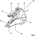
- Figure 3 which shows a detailed view of the remote control unit 26 on the handlebar 22, the input device 34 and the support selection buttons 30, 32 are arranged along a common line 60.
- the joystick 34 and the buttons 30, 32 are arranged one below the other in such a way that they can be operated ergonomically with the driver's thumb. A safety-critical grip by the driver is not required to operate the support selection buttons 30, 32 and joystick 34.
- the joystick 34 is square with mushroom-shaped rounded edges and can be moved in all four directions (up and down; left and right), with menu items being selected by pressing the joystick 34 (press function). Menu navigation and selection of menu items are carried out using the multifunctional joystick 34, so that no further control elements are required.
- the remote control unit 26 is therefore extremely compact and aesthetically pleasing.
- the joystick 34 has a frame-like backlit symbol 36, in particular a rectangle with rounded corners.
- the support selection buttons 30, 32 are arranged at an angle ⁇ in the range of approximately 120° to 170°, preferably approximately 155°.
- the selection of the support level can be made ergonomically with the driver's thumb.
- the support selection buttons 30, 32 form a concave section. The thumb can rest between the buttons 30, 32 arranged one above the other, so that the operation is intuitive, with the support selection button 30 being able to increase the
- the support level is arranged at the front and top in the direction of travel and the support selection button 32 for reducing the support level is arranged at the rear and below in the direction of travel.
- the support selection buttons 30, 32 are arranged at an angle sloping towards the driver's hand. The operation can be carried out ergonomically preferably with the driver's thumb.
- the support selection button 30 for increasing the support level is marked with a plus symbol and the support selection button 32 for decreasing the support level is marked with a minus symbol (see Figure 3 ).
- the symbols are backlit and can therefore be seen even in poor visibility conditions.
- the support selection buttons 30, 32 of the remote control unit 26 have a free actuating section 38 facing the driver's hand and an elastically designed common end section 40.
- the remote control unit 26 also has a wide rectangular light switch 42 which is arranged centrally and laterally offset in the area between the support selection buttons 30, 32.
- the light switch 42 is arranged in the direction away from the driver's hand next to the support selection buttons 30, 32 in the area of their end sections 40.
- the light switch 42 preferably has three functions, each of which is activated sequentially by pressing a button: hold button down (>2s) light on/off; press button to switch on low beam, second press to switch on high beam.
- hold button down >2s
- the advantage is therefore one button for light On/Low/High/Off.
- the light switch has a backlit light symbol.
- FIG. 5 which shows a further detailed illustration of the remote control unit 26, the electric bicycle shown is provided with an electronic circuit of the motor transmission, wherein the remote control unit 26 has a rocker switch 46 mounted centrally along a pivot axis 44 for gear selection.
- the rocker switch 44 has according to Figure 3 two actuating surfaces 48, 50, with a first actuating surface 48 being arranged on a side facing the driver's hand and a second actuating surface 50 being arranged on a side facing away from the driver's hand.
- Joystick 36, support selection buttons 30, 32 and rocker switch 46 are arranged along a common line 60.
- the buttons are arranged one below the other in such a way that they can be operated ergonomically with the driver's thumb. The driver does not need to change his grip, which is critical for safety, to operate support selection buttons 30, 32, joystick 36 and rocker switch 46.
- the remote control unit 26 has an upper part 52 and a modularly replaceable lower part 54, with the rocker switch 46 being assigned to a support arm 56 of the lower part 54 that extends in an arc-shaped manner in the direction of the driver's hand.
- the remote control unit 26 can therefore be adapted in a modular manner to bicycles with and without electric motor transmission.
- a lower part designed as a clamp half is mounted with or without a rocker switch.
- the version without a rocker switch is not shown.
- the support arm is also omitted here.
- the upper part 52 and lower part 54 are electrically connected by means of an internal flexible band (not shown).
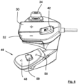
- the rocker switch 46 has a square automatic button 58 arranged approximately in the middle.
- the automatic button 58 does not rock with the rocker switch 46 and activates the automatic gear selection.
- the joystick 34, support selection buttons 30, 32 and rocker switch 46 run along a convexly curved common line 60 (dashed line in Figure 5 ), the curvature of which is ergonomically adapted to the range of motion of the driver's thumb.
- the invention can be implemented universally on all types of bicycles, especially mountain bikes (both in hardtail and full suspension design), but also on other bicycles, e.g. road bike frames, and thus ultimately results in a touring, city or cross bike or other modern types of bicycle. Due to the compact, elegant design, it enables the construction of bicycles that largely combine the advantages of a classic bicycle and an electric bicycle.
- a remote control unit 26 for the display unit 24 of an electric bicycle 1 wherein the remote control unit 26 is in the region of a handlebar grip 28 is arranged away from the display unit 24 and has support selection buttons 30, 32 for selecting the support level and at least one input device 34 for menu navigation and selection of menu items shown on the display unit 24. According to the invention, input device 34 and support selection buttons 30, 32 are arranged along a common line 60. Also disclosed is an electric bicycle 1 with such a remote control unit 26.
Landscapes
- Engineering & Computer Science (AREA)
- Mechanical Engineering (AREA)
- Chemical & Material Sciences (AREA)
- Combustion & Propulsion (AREA)
- Transportation (AREA)
- Theoretical Computer Science (AREA)
- General Engineering & Computer Science (AREA)
- Human Computer Interaction (AREA)
- Physics & Mathematics (AREA)
- General Physics & Mathematics (AREA)
- Steering Devices For Bicycles And Motorcycles (AREA)
- Mechanical Control Devices (AREA)
- Automatic Cycles, And Cycles In General (AREA)
- Battery Mounting, Suspending (AREA)
Description
- Die vorliegende Erfindung betrifft ein Elektrofahrrad gemäß dem Oberbegriff des Anspruchs 1.
- Elektrofahrräder, beispielsweise Pedelecs oder E-Bikes, erfreuen sich als leicht zu handhabendes, emissionsfreies Fortbewegungsmittel großer Beliebtheit. Für unterschiedliche Einsatzfelder sind besonders geeignete Fahrradtypen verfügbar. Hierzu gehören u.a. für den Freizeiteinsatz oder den Weg zur Arbeit auf der Straße oder im leichten Gelände optimierte Fahrräder (bspw. Citybikes oder Tourenbikes) und die für den Einsatz im Gelände und speziell auch bergigem Gelände entwickelten E-Mountainbikes (E-MTB) in verschiedenen Ausführungen. Elektrofahrräder bieten die Möglichkeit ohne Überbeanspruchung des Fahrers den Einsatzradius zu vergrößern und die durchschnittliche Fahrgeschwindigkeit zu erhöhen.
- Aus dem Stand der Technik sind Elektrofahrräder bekannt, welche neben einer Antriebseinheit und einer Batterieeinheit auch eine Anzeigeeinheit und eine Fernbedienungseinheit (engl. Remote) für die Anzeigeeinheit aufweisen. Die Fernbedienungseinheit ist im Bereich eines Lenkergriffes entfernt von der Anzeigeeinheit angeordnet und mit Unterstützungswahltasten für die Wahl der Unterstützungsstufe des Elektroantriebs versehen. Ferner weist die Fernbedienungseinheit ein Eingabegerät zur Menü-Navigation und Auswahl von auf der Anzeigeeinheit dargestellten Menüpunkten auf. Nachteilig bei derartigen Fernbedienungseinheiten ist, dass die häufig verwendeten Unterstützungswahltasten sowie das Eingabegerät nebeneinander angeordnet und daher nicht ergonomisch vom Daumen des Fahrers betätigbar sind. Häufig ist ein sicherheitskritisches Umgreifen des Fahrers zur Bedienung des Eingabegeräts notwendig. Derartige Anzeigeeinheiten und Fernbedienungseinheiten werden etwa in der
US 2012/049483 A1 sowie derUS 6 204 752 B1 beschrieben. DokumentUS 6 204 752 B1 offenbart den Oberbegriff des Anspruchs 1. - Der Erfindung liegt daher die Aufgabe zugrunde, ein neuartiges Elektrofahrrad bereitzustellen, welche elektrisch unterstützte Mobilität mit den Ansprüchen sportlich und Lifestyle-orientierter Radfahrer in Übereinstimmung bringt.
- Diese Aufgabe wird durch ein Elektrofahrrad gemäß dem Anspruch 1 gelöst.
- Ein erfindungsgemäßes Elektrofahrrad mit einer Fernbedienungseinheit für die Anzeigeeinheit des Elektrofahrrads ist im Bereich eines Lenkergriffes entfernt von der Anzeigeeinheit angeordnet und weist Unterstützungswahltasten für die Wahl der Unterstützungsstufe, eine Schaltwippe zur Gangwahl sowie zumindest ein Eingabegerät zur Menü-Navigation und Auswahl von auf der Anzeigeeinheit dargestellten Menüpunkten auf. Erfindungsgemäß verlaufen in Richtung der Lenkergriffachse betrachtet Eingabegerät, Unterstützungswahltasten und Schaltwippe vorzugsweise entlang einer konvex bogenförmigen gemeinsamen Linie, deren Krümmungsverlauf ergonomisch an den Bewegungsbereich des Fahrerdaumens angepasst ist. Das Eingabegerät und die Tasten sind vorzugsweise untereinander derart angeordnet, dass diese mit dem Daumen des Fahrers ergonomisch bedienbar sind. Ein sicherheitskritisches Umgreifen des Fahrers ist zur Bedienung von Unterstützungswahltasten und Eingabegerät nicht erforderlich.
- Bei einem besonders bevorzugten Ausführungsbeispiel der Erfindung ist das Eingabegerät als Joystick ausgebildet. Die Menü-Navigation und Auswahl von auf der Anzeigeeinheit dargestellten Menüpunkten kann dadurch intuitiv und ergonomisch bevorzugt mit dem Daumen des Fahrers erfolgen.
- Der Joystick ist vorzugsweise in alle vier Richtungen beweglich (nach oben und unten; nach links und rechts), wobei die Auswahl/Selektion von Menüpunkten mittels Druck auf den Joystick erfolgt (Druckfunktion). Die Menü-Navigation und Auswahl der Menüpunkte erfolgt mit dem multifunktionalen Joystick, so dass keine weiteren Bedienelemente erforderlich sind. Die Fernbedienungseinheit ist dadurch äußerst kompakt und ästhetisch ansprechend ausgebildet. Der Joystick kann ein hinterleuchtetes Symbol, insbesondere ein Rechteck mit abgerundeten Ecken aufweisen.
- Erfindungsgemäß sind die Unterstützungswahltasten zueinander geneigt angeordnet. Die Wahl der Unterstützungsstufe kann hierbei ergonomisch mit dem Daumen des Fahrers erfolgen. Die Unterstützungswahltasten bilden vorzugsweise einen konkaven Abschnitt aus. Der Daumen kann zwischen den übereinander angeordneten Tasten ruhen, so dass die Betätigung intuitiv erfolgt, wobei die Unterstützungswahltaste zur Erhöhung der Unterstützungsstufe vorzugsweise in Fahrtrichtung vorne und die Unterstützungswahltaste zur Verringerung der Unterstützungsstufe in Fahrtrichtung hinten angeordnet ist.
- Weiterhin wird es bevorzugt, wenn die Unterstützungswahltasten in Richtung der Hand des Fahrers geneigt angeordnet sind. Die Bedienung kann ergonomisch bevorzugt mit dem Daumen des Fahrers erfolgen.
- Die Unterstützungswahltaste zur Erhöhung der Unterstützungsstufe ist vorzugsweise mit einem Plus-Symbol und die Unterstützungswahltaste zur Verringerung der Unterstützungsstufe mit einem Minus-Symbol gekennzeichnet. Die Symbole sind vorzugsweise hinterleuchtet und dadurch auch bei schlechten Sichtverhältnissen erkennbar.
- Als fertigungstechnisch und für die Bedienung vorteilhaft hat es sich erwiesen, wenn der freie, Betätigungsabschnitt der Hand des Fahrers zugewandt angeordnet ist.
- Gemäß einer bevorzugten Ausführungsform der Erfindung ist ein Lichtschalter im Bereich zwischen den Unterstützungswahltasten seitlich versetzt angeordnet. Vorzugsweise ist der Lichtschalter in Richtung entfernt von der Hand des Fahrers neben den Unterstützungswahltasten angeordnet. Als besonders ergonomisch hat es sich erwiesen, wenn der Lichtschalter mittig zwischen den Unterstützungswahltasten seitlich versetzt angeordnet ist.
- Der Lichtschalter weist bevorzugt drei Funktionen auf, welche jeweils durch Tastendruck sequentiell aktiviert werden: Taste gedrückt halten (>2s) Licht ein/aus; Tastendruck Abblendlicht, zweiter Tastendruck Licht aufblenden. Vorteil daher eine Taste für Light On/Low/High/Off. Der Lichtschalter kann ein hinterleuchtetes Lichtsymbol aufweisen.
- Bei Elektrofahrrädern mit einer elektronischen Schaltung des Motorgetriebes weist die Fernbedienungseinheit vorzugsweise eine mittig entlang einer Schwenkachse gelagerte Schaltwippe zur Gangwahl auf. Erfindungsgemäß vorteilhaft ist es, wenn die Schaltwippe zwei Betätigungsflächen aufweist, wobei eine erste Betätigungsfläche auf einer der Hand des Fahrers zugewandten Seite und eine zweite Betätigungsfläche auf einer der Hand des Fahrers abgewandten Seite angeordnet ist. Eingabegerät, Unterstützungswahltasten und Schaltwippe sind vorzugsweise entlang einer gemeinsamen Linie angeordnet. Die Tasten sind vorzugsweise untereinander derart angeordnet, dass diese mit dem Daumen des Fahrers ergonomisch bedienbar sind. Ein sicherheitskritisches Umgreifen des Fahrers ist zur Bedienung von Unterstützungswahltasten, Eingabegerät und Schaltwippe nicht erforderlich.
- Bei einer bevorzugten Ausführungsform der Fernbedienungseinheit hat diese ein Oberteil und ein modular auswechselbares Unterteil, wobei die Schaltwippe dem Unterteil zugeordnet ist. Die Fernbedienungseinheit ist daher modular an Fahrräder mit und ohne elektrisches Motorgetriebe anpassbar. Hierzu wird wahlweise ein als Schellenhälfte ausgebildete Unterteil mit bzw. ohne Schaltwippe montiert. Ein Befestigungsabschnitt des Oberteil und des Unterteil umgreift vorzugsweise jeweils halb den Lenker. Oberteil und Unterteil sind vorzugsweise elektrisch mittels eines Flexbands verbunden.
- Die Schaltwippe hat vorzugsweise eine etwa mittig angeordnete Automatik-Taste. Die Automatik-Taste wippt bevorzugt nicht mit und aktiviert die automatische Gangwahl. Beispielsweise den ersten oder zweiten Gang des Motorgetriebes.
- In Richtung der Lenkergriffachse betrachtet verlaufen Eingabegerät, Unterstützungswahltasten und Schaltwippe vorzugsweise entlang einer konvex bogenförmigen gemeinsamen Linie, deren Krümmungsverlauf ergonomisch an den Bewegungsbereich des Fahrerdaumens angepasst ist.
- Die Fernbedienungseinheit hat vorzugsweise einen Vibrationsmotor. Beispielsweise kann mittels einer kurzen Vibration das Erreichen der höchsten Unterstützungsstufe signalisiert werden. Ferner kann mittels einer kurzen Vibration ein Schaltvorgang vorgeschlagen werden. Vorzugsweise erfolgt ein Gangvorschlag auf der Anzeigeeinheit, bspw. Pfeil nach oben auf Display als Vorschlag hochzuschalten, wobei die Vibration den Fahrer aufmerksam macht, dass die Anzeigeeinheit eine neue Information zeigt.
- Bei einem besonders bevorzugten Ausführungsbeispiel der Erfindung sind ferner eine elektronische Steuereinheit, eine Antriebseinheit und eine Batterieeinheit vorgesehen. Als besonders vorteilhaft hat es ich erwiesen, wenn die elektronische Steuereinheit im Sitzrohr des Fahrradrahmens angeordnet ist. Dadurch wird eine hochintegrierte Interaktion zwischen Rahmen und Einbauelementen erreicht. Die Bauweise der insbesondere im Unterrohr des Fahrradrahmens angeordneten Batterieeinheit ist nicht eingeschränkt und es steht mehr Bauraum für die Batteriezellen und damit eine hohe Reichweite zur Verfügung. Aufgrund der thermischen Entkoppelung von Batterieeinheit und elektronischer Steuereinheit wird ein hoher Wirkungsgrad erreicht. Spezielle Batteriegehäuse mit Befestigungsmöglichkeit für die Steuereinheit sind nicht erforderlich. Insgesamt wird bei dieser Variante eine kompakte, homogene Rahmenform höchster Festigkeit erreicht. Das erfindungsgemäße Konzept wird daher auch den Ansprüchen eines lifestyle betonten, sportlich ambitionierten Fahrers gerecht.
- Als besonders vorteilhaft hat es sich erwiesen, wenn die elektronische Steuereinheit im unteren Bereich des Sitzrohrs benachbart zur Antriebseinheit angeordnet ist. Dadurch ist die elektrische Leitungslänge auf ein Minimum reduziert. Das Elektrofahrrad hat dadurch einen optimierten Rahmenquerschnitt mit konstruktiv und ästhetisch besten Eigenschaften bei optimiertem Bauraumbedarf.
- Bei einem bevorzugten Ausführungsbeispiel ist die elektronische Steuereinheit am rahmenseitigen Antriebsträger (Motorbracket) der Antriebseinheit befestigt. Dadurch werden keine weiteren Befestigungselemente benötigt. Eine Gewichtsreduzierung kann erreicht werden.
- Die elektronische Steuereinheit ist vorzugsweise lediglich an einem der Antriebseinheit zugewandten Endabschnitt mit Leitungsanschlüssen versehen, so dass der Aufbau vereinfacht und die Leitungslängen minimal sind. Alle Leitungen werden vorzugsweise im Rahmen unten herausgeführt.
- Gemäß einer besonders bevorzugten Ausführungsform der Erfindung ist oberhalb der elektronischen Steuereinheit zumindest ein Anschlag, insbesondere ein Befestigungselement der Flaschenhalterung, bspw. eine Flaschenhalterbuchse, für die Sattelstütze angeordnet. Dadurch ist verhindert, dass die elektronische Steuereinheit von einer langen Sattelstütze beschädigt werden kann.
- Vorzugsweise sind zumindest eine Signalleitung der Fernbedienungseinheit mit der Anzeigeeinheit und mindestens eine elektrische Leitung der Anzeigeeinheit mit der elektronischen Steuereinheit verbunden. Als besonders vorteilhaft hat es sich erwiesen, wenn lediglich eine Sammelleitung zwischen der Fernbedienungseinheit und der Anzeigeeinheit vorgesehen ist. Ferner ist es besonders vorteilhaft, wenn lediglich eine Sammelleitung zwischen der Anzeigeeinheit und der elektronischen Steuereinheit vorgesehen ist. Die Anzahl der zu verlegenden Leitungen und damit Gewicht sowie Montageaufwand sind daher minimiert.
- Besonders vorteilhaft ist es, wenn die Bremssignalleitungen unmittelbar mit der Anzeigeeinheit verbunden sind. Dadurch ist lediglich eine elektrische Leitung zwischen der elektronischen Steuereinheit und der Anzeigeeinheit erforderlich. Die Anzahl der Leitungen ist reduziert. Bei der Bremsbetätigung wird das Bremslicht aktiviert.
- Entsprechend wird es bevorzugt, wenn die Fernbedienungseinheit mit einem einzelnen Sammelkabel, welches mehrere Signalleitungen beinhaltet, mit der Anzeigeeinheit verbunden ist.
- Gemäß eines besonders bevorzugten Ausführungsbeispiels der Erfindung sind Sensorleitungen jeweils unmittelbar mit der elektronischen Steuereinheit verbunden. Die Anzahl der Leitungen ist hierbei ebenfalls reduziert. Hierbei können insbesondere vorgesehen sein: Sensor des Seitenständers (Sicherheitsdeaktivierung bei heruntergeklapptem Ständer), Sensor des Getriebes, Beschleunigungssensoren (3D-Gyro und Accelometer), Sensor zur Erfassung einer Fahrradfaltung bei Falträdern, Drucksensoren und Temperatursensoren.
- Die Kommunikation erfolgt vorzugsweise mittels CAN-Bus-Verfahren, besonders bevorzugt CAN-Open-Verfahren. Ein CAN-Translator ist bei Anpassungserfordernissen vorgesehen.
- Die Erfindung kann universell bei allen Typen von Fahrrädern, insbesondere bei Mountainbikes (sowohl in Hardtail- oder Full-Suspension-Bauweise), aber auch bei anderen Fahrrädern, bspw. Straßenrad-Rahmen realisiert werden und somit letztlich ein Touren-, City- oder Cross-Rad oder andere moderne Fahrradtypen ergeben. Sie ermöglicht aufgrund der kompakten, formschönen Bauweise den Aufbau von Rädern, die weitgehend die Vorzüge eines klassischen Fahrrads und eines Elektrofahrrads in sich vereinen.
- Weitere bevorzugte Ausführungsformen sind Gegenstand der Unteransprüche.
- Im Folgenden wird eine bevorzugte Ausführungsform der vorliegenden Erfindung unter Bezugnahme auf die beiliegenden Zeichnungen näher erläutert. Dabei zeigen die Zeichnungen im Einzelnen:
-
Figur 1 eine Seitenansicht eines erfindungsgemäßen Elektrofahrrads, -
Figur 2 eine Detaildarstellung des Elektrofahrrads ausFigur 1 im Bereich des Fahrradlenkers, -
Figur 3 eine Detaildarstellung der Fernbedienungseinheit am Lenker, -
Figur 4 eine Seitenansicht der Fernbedienungseinheit am Lenker, -
Figur 5 eine weitere Detaildarstellung der Fernbedienungseinheit und -
Figur 6 eine weitere Detaildarstellung der Fernbedienungseinheit. -
Figur 1 zeigt eine Seitenansicht eines erfindungsgemäßen Elektrofahrrads 1 mit einem exemplarisch als Diamantrahmen ausgebildeten Fahrradrahmen 2 mit einem Unterrohr 4, einem Oberrohr 6, einem Sitzrohr 8, einem Steuerrohr 10, einem Antriebsträger 12 für eine Antriebseinheit 14 sowie Sattelstreben 16 und Unterstreben 18 sowie eine Batterieeinheit 20. - Wie insbesondere
Figur 2 zu entnehmen ist, welche eine Detaildarstellung des Elektrofahrrads 1 ausFigur 1 im Bereich des Fahrradlenkers 22 zeigt, ist eine mittig auf dem Lenker 22 angeordnete Anzeigeeinheit 24 und eine Fernbedienungseinheit 26 vorgesehen. Die Fernbedienungseinheit 26 ist im Bereich eines linken Lenkergriffes 28 entfernt von der Anzeigeeinheit 24 angeordnet und weist zwei Unterstützungswahltasten 30, 32 für die Wahl der Motor-Unterstützungsstufe sowie ein als Joystick 34 ausgebildetes Eingabegerät zur Menü-Navigation und Auswahl von auf der Anzeigeeinheit 24 dargestellten Menüpunkten auf. - Gemäß
Figur 3 , welche eine Detaildarstellung der Fernbedienungseinheit 26 am Lenker 22 zeigt, sind Eingabegerät 34 und Unterstützungswahltasten 30, 32 entlang einer gemeinsamen Linie 60 angeordnet. Der Joystick 34 und die Tasten 30, 32 sind untereinander derart angeordnet, dass diese mit dem Daumen des Fahrers ergonomisch bedienbar sind. Ein sicherheitskritisches Umgreifen des Fahrers ist zur Bedienung von Unterstützungswahltasten 30, 32 und Joystick 34 nicht erforderlich. - Der Joystick 34 ist quadratisch mit pilzförmig abgerundeten Kanten ausgebildet und in alle vier Richtungen beweglich (nach oben und unten; nach links und rechts), wobei die Auswahl/Selektion von Menüpunkten mittels Druck auf den Joystick 34 erfolgt (Druckfunktion). Die Menü-Navigation und Auswahl der Menüpunkte erfolgt mit dem multifunktionalen Joystick 34, so dass keine weiteren Bedienelemente erforderlich sind. Die Fernbedienungseinheit 26 ist dadurch äußerst kompakt und ästhetisch ansprechend ausgebildet. Der Joystick 34 weist ein rahmenartig hinterleuchtetes Symbol 36, insbesondere ein Rechteck mit abgerundeten Ecken auf.
- Wie insbesondere
Figur 4 zu entnehmen ist, welche eine Seitenansicht der Fernbedienungseinheit 26 am Lenker 22 zeigt, sind die Unterstützungswahltasten 30, 32 zueinander unter einem Winkel α im Bereich von etwa 120° bis 170°, vorzugsweise von etwa 155° geneigt angeordnet. Die Wahl der Unterstützungsstufe kann hierbei ergonomisch mit dem Daumen des Fahrers erfolgen. Die Unterstützungswahltasten 30, 32 bilden einen konkaven Abschnitt aus. Der Daumen kann zwischen den übereinander angeordneten Tasten 30, 32 ruhen, so dass die Betätigung intuitiv erfolgt, wobei die Unterstützungswahltaste 30 zur Erhöhung der Unterstützungsstufe in Fahrtrichtung vorne oben und die Unterstützungswahltaste 32 zur Verringerung der Unterstützungsstufe in Fahrtrichtung hinten und unterhalb angeordnet ist. Ferner sind die Unterstützungswahltasten 30, 32 in Richtung der Hand des Fahrers abfallend geneigt angeordnet sind. Die Bedienung kann ergonomisch bevorzugt mit dem Daumen des Fahrers erfolgen. - Die Unterstützungswahltaste 30 zur Erhöhung der Unterstützungsstufe ist mit einem Plus-Symbol und die Unterstützungswahltaste 32 zur Verringerung der Unterstützungsstufe mit einem Minus-Symbol gekennzeichnet (siehe
Figur 3 ). Die Symbole sind hinterleuchtet und dadurch auch bei schlechten Sichtverhältnissen erkennbar. - Als fertigungstechnisch und für die Bedienung vorteilhaft hat es sich erwiesen, wenn die Unterstützungswahltasten 30, 32 der Fernbedienungseinheit 26 einen freien, der Hand des Fahrers zugewandten Betätigungsabschnitt 38 sowie einen elastisch ausgebildeten gemeinsamen Endabschnitt 40 aufweisen.
- Die Fernbedienungseinheit 26 hat ferner einen breitformatig rechteckigen Lichtschalter 42 der im Bereich zwischen den Unterstützungswahltasten 30, 32 mittig, seitlich versetzt angeordnet ist. Der Lichtschalter 42 ist in Richtung entfernt von der Hand des Fahrers neben den Unterstützungswahltasten 30, 32 im Bereich derer Endabschnitte 40 angeordnet.
- Der Lichtschalter 42 weist bevorzugt drei Funktionen auf, welche jeweils durch Tastendruck sequentiell aktiviert werden: Taste gedrückt halten (>2s) Licht ein/aus; Tastendruck Abblendlicht, zweiter Tastendruck Licht aufblenden. Vorteil daher eine Taste für Light On/Low/High/Off. Der Lichtschalter weist ein hinterleuchtetes Lichtsymbol auf.
- Wie insbesondere
Figur 5 zu entnehmen ist, welche eine weitere Detaildarstellung der Fernbedienungseinheit 26 zeigt, ist das dargestellte Elektrofahrrad mit einer elektronischen Schaltung des Motorgetriebes versehen, wobei die Fernbedienungseinheit 26 eine mittig entlang einer Schwenkachse 44 gelagerte Schaltwippe 46 zur Gangwahl aufweist. - Die Schaltwippe 44 hat gemäß
Figur 3 zwei Betätigungsflächen 48, 50, wobei eine erste Betätigungsfläche 48 auf einer der Hand des Fahrer zugewandten Seite und eine zweite Betätigungsfläche 50 auf einer der Hand des Fahrers abgewandten Seite angeordnet ist. Joystick 36, Unterstützungswahltasten 30, 32 und Schaltwippe 46 sind entlang einer gemeinsamen Linie 60 angeordnet. Die Tasten sind untereinander derart angeordnet, dass diese mit dem Daumen des Fahrers ergonomisch bedienbar sind. Ein sicherheitskritisches Umgreifen des Fahrers ist zur Bedienung von Unterstützungswahltasten 30, 32, Joystick 36 und Schaltwippe 46 nicht erforderlich. - Wie insbesondere in den
Figuren 4 und5 dargestellt ist, hat die Fernbedienungseinheit 26 ein Oberteil 52 und ein modular auswechselbaren Unterteil 54, wobei die Schaltwippe 46 einem sich bogenförmig gekrümmt in Richtung der Hand des Fahrers erstreckenden Tragarm 56 des Unterteils 54 zugeordnet ist. Die Fernbedienungseinheit 26 ist daher modular an Fahrräder mit und ohne elektrisches Motorgetriebe anpassbar. Hierzu wird ein als Schellenhälfte ausgebildete Unterteil mit bzw. ohne Schaltwippe montiert. Die Version ohne Schaltwippe ist nicht dargestellt. Hierbei entfällt auch der Tragarm. Oberteil 52 und Unterteil 54 sind elektrisch mittels eines innenliegenden Flexbands verbunden (nicht dargestellt). - Wie insbesondere
Figur 6 zu entnehmen ist, welche eine weitere Detaildarstellung der Fernbedienungseinheit 26 zeigt, hat die Schaltwippe 46 eine etwa mittig angeordnete, quadratische Automatik-Taste 58. Die Automatik-Taste 58 wippt nicht mit der Wippe 46 und aktiviert die automatische Gangwahl. - In Richtung der Lenkergriffachse betrachtet verlaufen Joystick 34, Unterstützungswahltasten 30, 32 und Schaltwippe 46 entlang einer konvex bogenförmigen gemeinsamen Linie 60 (gestrichelte Linie in
Figur 5 ), deren Krümmungsverlauf ergonomisch an den Bewegungsbereich des Fahrerdaumens angepasst ist. - Die Erfindung kann universell bei allen Typen von Fahrrädern, insbesondere bei Mountainbikes (sowohl in Hardtail- oder Full-Suspension-Bauweise), aber auch bei anderen Fahrrädern, bspw. Straßenrad-Rahmen realisiert werden und somit letztlich ein Touren-, City- oder Cross-Rad oder andere moderne Fahrradtypen ergeben. Sie ermöglicht aufgrund der kompakten, formschönen Bauweise den Aufbau von Rädern, die weitgehend die Vorzüge eines klassischen Fahrrads und eines Elektrofahrrads in sich vereinen.
- Die Ausführung der Erfindung ist nicht auf die in den Figuren gezeigten und oben erläuterten Beispiele beschränkt, sondern ebenso in einer Vielzahl von Abwandlungen eines Fachmanns möglich.
- Offenbart ist eine Fernbedienungseinheit 26 für die Anzeigeeinheit 24 eines Elektrofahrrads 1, wobei die Fernbedienungseinheit 26 im Bereich eines Lenkergriffes 28 entfernt von der Anzeigeeinheit 24 angeordnet ist und Unterstützungswahltasten 30, 32 für die Wahl der Unterstützungsstufe sowie zumindest ein Eingabegerät 34 zur Menü-Navigation und Auswahl von auf der Anzeigeeinheit 24 dargestellten Menüpunkten aufweist. Erfindungsgemäß sind Eingabegerät 34 und Unterstützungswahltasten 30, 32 entlang einer gemeinsamen Linie 60 angeordnet. Weiterhin offenbart ist ein Elektrofahrrad 1 mit einer derartigen Fernbedienungseinheit 26.
-
- 1
- Elektrofahrrad
- 2
- Fahrradrahmen
- 4
- Unterrohr
- 6
- Oberrohr
- 8
- Sitzrohr
- 10
- Steuerrohr
- 12
- Antriebsträger
- 14
- Antriebseinheit
- 16
- Sattelstrebe
- 18
- Unterstrebe
- 20
- Batterieeinheit
- 22
- Lenker
- 24
- Anzeigeeinheit
- 26
- Fernbedienungseinheit
- 28
- linker Lenkergriff
- 30
- Unterstützungswahltaste
- 32
- Unterstützungswahltaste
- 34
- Joystick
- 36
- Symbol
- 38
- Betätigungsabschnitt
- 40
- Endabschnitt
- 42
- Lichtschalter
- 44
- Schwenkachse
- 46
- Schaltwippe
- 48
- Betätigungsfläche
- 50
- Betätigungsfläche
- 52
- Oberteil
- 54
- Unterteil
- 56
- Tragarm
- 58
- Automatik-Taste
- 60
- Linie
Claims (10)
- Elektrofahrrad mit einer Fernbedienungseinheit für die Anzeigeeinheit (24) des Elektrofahrrads (1), wobei die Fernbedienungseinheit (26) im Bereich eines Lenkergriffes (28) entfernt von der Anzeigeeinheit (24) angeordnet ist und Unterstützungswahltasten (30, 32) für die Wahl der Unterstützungsstufe, eine Schaltwippe (46) zur Gangwahl sowie zumindest ein Eingabegerät (34) zur Menü-Navigation und Auswahl von auf der Anzeigeeinheit (24) dargestellten Menüpunkten aufweist, dadurch gekennzeichnet dass in Richtung der Lenkergriffachse betrachtet verlaufen das Eingabegerät (34), die Unterstützungswahltasten (30, 32) und die Schaltwippe (46) entlang einer konvex bogenförmigen gemeinsamen Linie (60) deren Krümmungsverlauf ergonomisch an den Bewegungsbereich des Fahrerdaumens angepasst ist, und dass die Unterstützungswahltasten (30, 32) zueinander geneigt angeordnet sind und einen konkaven Abschnitt zur ergonomischen Bedienung mit dem Daumen eines Fahrers ausbilden.
- Elektrofahrrad nach Anspruch 1, wobei das Eingabegerät als Joystick (34) ausgebildet ist.
- Elektrofahrrad nach Anspruch 2, wobei der Joystick (34) in vier Richtungen beweglich ist und die Auswahl/Selektion von Menüpunkten mittels Druck auf den Joystick (34) erfolgt.
- Elektrofahrrad nach einem der vorhergehenden Ansprüche, wobei die Unterstützungswahltasten (30, 32) einen freien Betätigungsabschnitt (38) sowie einen elastisch ausgebildeten Endabschnitt (40) aufweisen.
- Elektrofahrrad nach einem der vorhergehenden Ansprüche, wobei ein Lichtschalter (42) im Bereich zwischen den Unterstützungswahltasten (30, 32) seitlich versetzt angeordnet ist.
- Elektrofahrrad nach Anspruch 5, wobei der Lichtschalter (42) mehrere Funktionen aufweist, welche sequentiell durch Tastendruck aktiviert werden.
- Elektrofahrrad nach einem der vorhergehenden Ansprüche, mit einer mittig entlang einer Schwenkachse (44) gelagerten Schaltwippe (46) zur Gangwahl.
- Elektrofahrrad nach Anspruch 7, mit einem Oberteil (52) und einem modular auswechselbaren Unterteil (54), wobei die Schaltwippe (46) dem Unterteil (54) zugeordnet ist.
- Elektrofahrrad nach einem der Ansprüche 7 oder 8, wobei die Schaltwippe (46) eine etwa mittig angeordnete Automatik-Taste (58) aufweist.
- Elektrofahrrad nach einem der vorhergehenden Ansprüche, wobei die Fernbedienungseinheit (26) einen Vibrationsmotor aufweist.
Applications Claiming Priority (4)
| Application Number | Priority Date | Filing Date | Title |
|---|---|---|---|
| DE102015216178.1A DE102015216178B4 (de) | 2015-08-25 | 2015-08-25 | Elektrofahrrad |
| DE102015216186.2A DE102015216186B4 (de) | 2015-08-25 | 2015-08-25 | Fernbedienungseinheit und Elektrofahrrad |
| DE102015216188.9A DE102015216188B3 (de) | 2015-08-25 | 2015-08-25 | Anzeigeeinheit und Elektrofahrrad |
| PCT/EP2016/070085 WO2017032836A1 (de) | 2015-08-25 | 2016-08-25 | Fernbedienungseinheit und elektrofahrrad |
Publications (2)
| Publication Number | Publication Date |
|---|---|
| EP3337720A1 EP3337720A1 (de) | 2018-06-27 |
| EP3337720B1 true EP3337720B1 (de) | 2024-12-04 |
Family
ID=56842813
Family Applications (3)
| Application Number | Title | Priority Date | Filing Date |
|---|---|---|---|
| EP16757869.9A Active EP3337720B1 (de) | 2015-08-25 | 2016-08-25 | Elektrofahrrad |
| EP16760020.4A Active EP3337722B1 (de) | 2015-08-25 | 2016-08-25 | Anzeigeeinheit und elektrofahrrad |
| EP16759723.6A Active EP3337721B1 (de) | 2015-08-25 | 2016-08-25 | Elektrofahrrad |
Family Applications After (2)
| Application Number | Title | Priority Date | Filing Date |
|---|---|---|---|
| EP16760020.4A Active EP3337722B1 (de) | 2015-08-25 | 2016-08-25 | Anzeigeeinheit und elektrofahrrad |
| EP16759723.6A Active EP3337721B1 (de) | 2015-08-25 | 2016-08-25 | Elektrofahrrad |
Country Status (6)
| Country | Link |
|---|---|
| US (3) | US10647381B2 (de) |
| EP (3) | EP3337720B1 (de) |
| JP (3) | JP6797188B2 (de) |
| KR (3) | KR102626624B1 (de) |
| CN (3) | CN108430862B (de) |
| WO (3) | WO2017032833A1 (de) |
Families Citing this family (28)
| Publication number | Priority date | Publication date | Assignee | Title |
|---|---|---|---|---|
| JP6797188B2 (ja) | 2015-08-25 | 2020-12-09 | バイクテック アーゲーBiketec Ag | 電気自転車 |
| KR102620256B1 (ko) * | 2016-11-30 | 2024-01-03 | (주)벨로스타 | 전기 자전거의 모터속도 제어 방법 |
| ES2751877T3 (es) * | 2017-03-07 | 2020-04-02 | Hong Xue | Bastidor para vehículos asistidos eléctricamente y vehículos asistidos eléctricamente |
| WO2018185062A1 (en) * | 2017-04-04 | 2018-10-11 | Matsuura Frontini Matteo Giuseppe | Modular electric bicycle |
| KR102371244B1 (ko) * | 2017-06-01 | 2022-03-04 | 현대자동차 주식회사 | 자전거 프레임 및 그의 제조방법 |
| WO2020022848A1 (ko) | 2018-07-26 | 2020-01-30 | 주식회사 엘지화학 | 가교 폴리올레핀 분리막 및 이의 제조방법 |
| US11046389B2 (en) | 2018-08-21 | 2021-06-29 | Specialized Bicycle Components, Inc. | Ebike battery mount |
| US11124259B2 (en) * | 2018-08-21 | 2021-09-21 | Specialized Bicycle Components, Inc. | Bicycle with housing loop stay |
| US12043344B2 (en) | 2018-08-21 | 2024-07-23 | Specialized Bicycle Components, Inc. | Bicycle with battery, motor and motor mount, wire routing, speed sensor, and dropper seat post |
| USD908543S1 (en) | 2018-09-18 | 2021-01-26 | Birota | Frame for cycle |
| JP2020055361A (ja) * | 2018-09-28 | 2020-04-09 | 本田技研工業株式会社 | 自動二輪車のハンドルスイッチ |
| JP7325970B2 (ja) * | 2019-02-01 | 2023-08-15 | 株式会社シマノ | 人力駆動車用のドライブユニットおよび人力駆動車用のバッテリ保持装置 |
| TWI697431B (zh) * | 2019-05-08 | 2020-07-01 | 彥豪金屬工業股份有限公司 | 自行車車頭 |
| FI128933B (fi) | 2019-05-31 | 2021-03-31 | Revonte Oy | Käyttöjärjestelmä ja kauko-ohjain |
| DE102019208810A1 (de) * | 2019-06-18 | 2020-12-24 | Robert Bosch Gmbh | Aufnahmevorrichtung zum Befestigen eines mobilen Endgeräts an einem Modul |
| NL2024186B1 (nl) * | 2019-11-07 | 2021-09-29 | Vanmoof Bv | Rijwielstuur |
| JP7466094B2 (ja) * | 2020-05-14 | 2024-04-12 | パナソニックIpマネジメント株式会社 | 電動アシスト自転車 |
| EP4122806A1 (de) | 2021-07-23 | 2023-01-25 | MAHLE International GmbH | Bedienelement für ein fahrrad |
| WO2023126649A1 (en) | 2021-12-27 | 2023-07-06 | Bosch Car Multimedia Portugal S.A | Physical input device for a human-machine interface, to be mounted on a bicycle or motorcycle handlebar |
| NL2031283B1 (en) * | 2022-03-15 | 2023-09-27 | Vanmoof Bv | Electric bicycle and charging device for use in such an electric bicycle |
| CA216473S (en) * | 2022-06-07 | 2024-06-10 | Zhejiang Taotao Vehicles Co Ltd | Bicycle |
| CN115056912B (zh) * | 2022-08-03 | 2023-12-19 | 珠海蓝图运动科技股份有限公司 | 一种指拨与声光控制器组合结构及自行车 |
| USD1022806S1 (en) * | 2022-11-10 | 2024-04-16 | Zhejiang Taotao Vehicles Co., Ltd | Bicycle |
| JP2024100035A (ja) * | 2023-01-13 | 2024-07-26 | 株式会社シマノ | 報知装置、および、プログラム |
| CN117262098A (zh) * | 2023-08-31 | 2023-12-22 | 青岛迈金智能科技股份有限公司 | 指拨装置及骑行设备 |
| KR102931675B1 (ko) * | 2023-11-07 | 2026-02-25 | 국립금오공과대학교 산학협력단 | 리모컨 장치 |
| EP4671107A1 (de) * | 2024-06-28 | 2025-12-31 | Orbea, S. Coop. | Steuerungssystem für elektrofahrrad, hauptsteuervorrichtung und zusatzsteuervorrichtung dafür |
| JP2026006052A (ja) * | 2024-06-28 | 2026-01-16 | パナソニックIpマネジメント株式会社 | 操作装置 |
Citations (6)
| Publication number | Priority date | Publication date | Assignee | Title |
|---|---|---|---|---|
| JP2000163215A (ja) * | 1998-11-30 | 2000-06-16 | Sega Enterp Ltd | 操作装置 |
| US20080015017A1 (en) * | 2006-05-09 | 2008-01-17 | Nintendo Co., Ltd. | Game controller |
| US20080180233A1 (en) * | 2007-01-30 | 2008-07-31 | Campagnolo S.R.L. | Human-bicycle interaction device |
| US20120159328A1 (en) * | 2010-12-16 | 2012-06-21 | Harman International Industries, Incorporated | Handlebar audio controls |
| DE202013002491U1 (de) * | 2013-03-15 | 2014-06-17 | Rti Sports Vertrieb Von Sportartikeln Gmbh | Fahrradgriff-System |
| CN204077923U (zh) * | 2014-08-26 | 2015-01-07 | 苏州莱士格车业有限公司 | 电动自行车 |
Family Cites Families (81)
| Publication number | Priority date | Publication date | Assignee | Title |
|---|---|---|---|---|
| JPS58194979U (ja) * | 1982-06-22 | 1983-12-24 | 本田技研工業株式会社 | 二輪車のハンドルスイツチ装置 |
| US5798702A (en) * | 1996-04-18 | 1998-08-25 | Suzuki Motor Corporation | Residual battery capacity display device for electric vehicle |
| US5789702A (en) | 1996-05-17 | 1998-08-04 | Perella; Paul | Modular component of appliance housing |
| JP3490239B2 (ja) * | 1997-01-31 | 2004-01-26 | 株式会社シマノ | 自転車用表示装置の取付具 |
| US6401997B1 (en) * | 1998-09-10 | 2002-06-11 | E. Thomas Smerdon, Jr. | Bicycle-mounted liquid storage and delivery system and support bracket |
| TW543583U (en) * | 1998-12-16 | 2003-07-21 | Index Electronic Co Ltd | Speed control device for electromotive motorcycle |
| US6305241B1 (en) * | 1999-06-28 | 2001-10-23 | Shimano, Inc. | Handlebar adapter for mounting a bicycle display |
| US6204752B1 (en) * | 1999-11-24 | 2001-03-20 | Shimano Inc. | Bicycle display unit with backlight |
| JP2002033030A (ja) | 2000-07-17 | 2002-01-31 | Alps Electric Co Ltd | キースイッチ |
| US6400564B1 (en) * | 2000-09-14 | 2002-06-04 | Shimano Inc. | Switch guide for a bicycle control panel |
| US6584872B1 (en) * | 2000-10-31 | 2003-07-01 | Shimano Inc. | Bicycle handle mounting member |
| CN100352731C (zh) * | 2002-03-08 | 2007-12-05 | 株式会社岛野 | 一种自行车换档操作装置 |
| US6781510B2 (en) * | 2002-07-24 | 2004-08-24 | Shimano, Inc. | Bicycle computer control arrangement and method |
| EP1384659B1 (de) * | 2002-07-24 | 2009-12-23 | Shimano Inc. | Steuervorrichtung für Fahrradcomputer und Verfahren |
| US20040039522A1 (en) * | 2002-08-26 | 2004-02-26 | Star Jwo | Cycling route recording system for a bicycle |
| DE102004014035A1 (de) | 2004-03-19 | 2005-10-06 | Sram Deutschland Gmbh | Fahrrad-Gangschaltungseinrichtung |
| JP2006001438A (ja) * | 2004-06-18 | 2006-01-05 | Shimano Inc | 自転車用制御装置及び自転車用シートピラー |
| US20060047311A1 (en) * | 2004-08-26 | 2006-03-02 | Lutz David I | Expanded PTFE articles and method of making same |
| US7243937B2 (en) | 2005-02-18 | 2007-07-17 | Shimano, Inc. | Bicycle control apparatus |
| WO2006089256A2 (en) | 2005-02-18 | 2006-08-24 | Logitech Europe S.A. | Wireless headset with mic-side driver cut-off |
| US7272063B1 (en) | 2006-03-21 | 2007-09-18 | Infineon Technologies Ag | Memory with a temperature sensor, dynamic memory and memory with a clock unit and method of sensing a temperature of a memory |
| DE102006032016B4 (de) | 2006-07-10 | 2011-06-16 | Gruber Antrieb Gmbh & Co. Kg | Elektrischer Hilfsantrieb für ein Fahrrad |
| US7976048B2 (en) * | 2006-11-15 | 2011-07-12 | Good For You Good For The Planet, S.L. | Portable safety, entertainment and communication device for bicycles and control method |
| WO2008148104A1 (en) * | 2007-05-25 | 2008-12-04 | Novavax, Inc. | Novel vlps derived from cells that do not express a viral matrix or core protein |
| ITMI20071181A1 (it) * | 2007-06-12 | 2008-12-13 | Campagnolo Srl | Metodo di controllo elettronico di un cambio di bicicletta e sistema elettronico per bicicletta |
| US20090002198A1 (en) * | 2007-06-27 | 2009-01-01 | Bach Darren A | Marine throttle mounted stereo control |
| DE202007019659U1 (de) * | 2007-08-28 | 2015-04-01 | Trelock Gmbh | Anzeige- und Bedienungssystem für ein Fahrzeug |
| DE102007040738B4 (de) * | 2007-08-28 | 2015-06-25 | Trelock Gmbh | Anzeige- und Bedienungssystem für ein Fahrrad |
| US20100237120A1 (en) * | 2007-09-21 | 2010-09-23 | Muhlberger GmbH | Coupling device releasably attaching accessories to a bicycle |
| US8089009B2 (en) | 2007-10-30 | 2012-01-03 | Zippy Technology Corp. | Annular multi-instruction switch |
| ITMI20072407A1 (it) * | 2007-12-20 | 2009-06-21 | Campagnolo Srl | Apparecchiatura elettronica per bicicletta |
| US8525793B2 (en) * | 2008-05-30 | 2013-09-03 | Bombardier Recreational Products Inc. | Vehicle with a display device operated from a handlebar |
| CN201287793Y (zh) * | 2008-08-21 | 2009-08-12 | 许志坚 | 折叠电动自行车 |
| CH701675B1 (de) | 2009-08-20 | 2014-09-15 | Fairly Bike Mfg Co Ltd | Batteriehalterung. |
| US8801022B2 (en) | 2009-12-29 | 2014-08-12 | Mando Corporation | Folding type bicycle |
| KR101165591B1 (ko) * | 2010-04-14 | 2012-07-23 | 주식회사 만도 | 전기 자전거 |
| JP5566760B2 (ja) * | 2010-04-20 | 2014-08-06 | 株式会社シマノ | 自転車用ブレーキレバー及びそれを用いた自転車用回生制動制御装置 |
| JP5211102B2 (ja) * | 2010-04-28 | 2013-06-12 | 株式会社シマノ | 自転車用電装システム |
| JP5143867B2 (ja) | 2010-06-11 | 2013-02-13 | 株式会社シマノ | 自転車用の電装品制御システム |
| US8469381B2 (en) * | 2010-08-26 | 2013-06-25 | Cycling Sports Group, Inc. | Bicycle |
| DE102010039860A1 (de) * | 2010-08-27 | 2012-03-01 | Robert Bosch Gmbh | Komponentenüberwachung in einem elektrisch betriebenen Fahrzeug |
| CN103238195B (zh) | 2010-10-13 | 2016-08-24 | 沙夫纳Emv股份公司 | 摇臂开关单元 |
| JP2012179975A (ja) * | 2011-02-28 | 2012-09-20 | Shimano Inc | 自転車用サスペンション制御装置の設定装置および自転車用サスペンションの制御装置 |
| JP5649484B2 (ja) | 2011-03-07 | 2015-01-07 | 富士通コンポーネント株式会社 | 押釦式スイッチ装置 |
| EP2532571B1 (de) | 2011-06-10 | 2014-03-26 | Campagnolo S.r.l. | Am Fahrrad befestigte Vorrichtung und zugehöriges Montageverfahren |
| KR20130013115A (ko) * | 2011-07-27 | 2013-02-06 | (주) 임베디드 솔루션 | 전동식 자전거의 모터제어방법 및 시스템 |
| KR20130015664A (ko) * | 2011-08-04 | 2013-02-14 | 삼성전자주식회사 | 이미지 변환 장치 및 방법 |
| CN202320636U (zh) * | 2011-08-26 | 2012-07-11 | 深圳市恒威盈驰科技有限公司 | 采用led显示的电动自行车仪表 |
| JP5566975B2 (ja) | 2011-08-29 | 2014-08-06 | 株式会社シマノ | 自転車用制御装置 |
| DE102011084464B4 (de) * | 2011-10-13 | 2013-09-05 | Dewert Antriebs- Und Systemtechnik Gmbh | Mechanisch sperrbare Kabelfernbedienung |
| CN202429321U (zh) | 2011-12-20 | 2012-09-12 | 方文灿 | 一种电动车智能控制系统 |
| DE102012200597A1 (de) | 2012-01-17 | 2013-07-18 | Robert Bosch Gmbh | Vorrichtung zum Signalisieren von Informationen an den Fahrer eines Fahrrads |
| JP5871692B2 (ja) * | 2012-03-29 | 2016-03-01 | 本田技研工業株式会社 | 車両用トラクションコントロール表示装置 |
| US9302739B2 (en) * | 2012-06-18 | 2016-04-05 | Shimano, Inc. | Bicycle power control apparatus |
| DE202012007991U1 (de) | 2012-08-21 | 2013-12-04 | Rti Sports Vertrieb Von Sportartikeln Gmbh | Fahrradgriffsystem |
| CN202716986U (zh) * | 2012-08-24 | 2013-02-06 | 苏一清 | 一种电动自行车车架及使用该车架的电动自行车 |
| US9056651B2 (en) * | 2012-08-27 | 2015-06-16 | Shimano Inc. | Bicycle control device |
| KR20140038049A (ko) * | 2012-09-19 | 2014-03-28 | 주식회사 만도 | 전기 자전거 및 그 제어방법 |
| KR20140038024A (ko) | 2012-09-19 | 2014-03-28 | 주식회사 만도 | 전기 자전거 |
| CN202911871U (zh) * | 2012-11-14 | 2013-05-01 | 天津市三枪电动车有限公司 | 一种电动自行车的信息显示结构 |
| DE202012104592U1 (de) * | 2012-11-27 | 2012-12-17 | Matthias Rapp | Halterung für ein mobiles Kommunikationsgerät |
| JP5872999B2 (ja) | 2012-12-25 | 2016-03-01 | ブリヂストンサイクル株式会社 | 電動機付自転車 |
| US9726216B2 (en) | 2013-02-04 | 2017-08-08 | Shimano Inc. | Cable adjusting unit |
| US20140252746A1 (en) | 2013-03-06 | 2014-09-11 | Specialized Bicycle Components, Inc. | Bicycle electronic display and shift lever mount |
| PL2825000T3 (pl) * | 2013-07-10 | 2016-09-30 | Samo-ekranujący się pionowy liniowy akcelerator protonowy do terapii protonowej | |
| JP2015044463A (ja) * | 2013-08-28 | 2015-03-12 | パナソニック株式会社 | 車両用表示装置 |
| JP6229419B2 (ja) * | 2013-10-03 | 2017-11-15 | スズキ株式会社 | ハンドルスイッチ装置 |
| JP6220637B2 (ja) * | 2013-11-01 | 2017-10-25 | ヤマハ発動機株式会社 | 電動補助自転車 |
| JP6220636B2 (ja) * | 2013-11-01 | 2017-10-25 | ヤマハ発動機株式会社 | 電動補助自転車 |
| TW201524838A (zh) * | 2013-12-26 | 2015-07-01 | Jingtek Electronics Technology Co Ltd | 具無線遙控車子功能並附遙控器之主體螢幕 |
| DE102014208479A1 (de) | 2014-05-07 | 2015-11-12 | Schaeffler Technologies AG & Co. KG | Gangschaltung für ein Fahrrad und Fahrrad mit einer derartigen Gangschaltung |
| CN203958429U (zh) * | 2014-05-22 | 2014-11-26 | 天津市四海亨通自行车有限公司 | 冬日保暖电动自行车 |
| US9150272B1 (en) | 2014-07-16 | 2015-10-06 | Ford Global Technologies, Llc | Folding bicycle chain stay and frame |
| JP6309410B2 (ja) | 2014-09-24 | 2018-04-11 | 川崎重工業株式会社 | 鞍乗り型車両のエンジン支持構造 |
| US9402578B2 (en) | 2014-09-26 | 2016-08-02 | Shimano Inc. | Crank angle indicating system |
| JP3194818U (ja) * | 2014-09-29 | 2014-12-11 | 株式会社シマノ | 自転車用駆動ユニット |
| US9637191B2 (en) | 2014-11-26 | 2017-05-02 | Tennus Industrial Co., Ltd. | LED signaling device for a bicycle |
| US9592874B2 (en) | 2014-12-19 | 2017-03-14 | Meizhou XiuYing Enterprise Company Limited | Intelligent bicycle |
| US9272662B2 (en) | 2015-02-12 | 2016-03-01 | Meizhou XiuYing Enterprise Company Limited | Bicycle having an intelligent system |
| JP6797188B2 (ja) | 2015-08-25 | 2020-12-09 | バイクテック アーゲーBiketec Ag | 電気自転車 |
| US10363980B2 (en) | 2017-06-20 | 2019-07-30 | Tien Hsin Industries Co., Ltd. | Bicycle controlling device |
-
2016
- 2016-08-25 JP JP2018510874A patent/JP6797188B2/ja active Active
- 2016-08-25 WO PCT/EP2016/070082 patent/WO2017032833A1/de not_active Ceased
- 2016-08-25 CN CN201680061756.4A patent/CN108430862B/zh active Active
- 2016-08-25 KR KR1020187008401A patent/KR102626624B1/ko active Active
- 2016-08-25 CN CN201680061787.XA patent/CN108473178A/zh active Pending
- 2016-08-25 EP EP16757869.9A patent/EP3337720B1/de active Active
- 2016-08-25 WO PCT/EP2016/070081 patent/WO2017032832A1/de not_active Ceased
- 2016-08-25 JP JP2018510879A patent/JP6965238B2/ja active Active
- 2016-08-25 EP EP16760020.4A patent/EP3337722B1/de active Active
- 2016-08-25 EP EP16759723.6A patent/EP3337721B1/de active Active
- 2016-08-25 KR KR1020187008403A patent/KR102642511B1/ko active Active
- 2016-08-25 KR KR1020187008402A patent/KR102679693B1/ko active Active
- 2016-08-25 CN CN201680061688.1A patent/CN108473177B/zh active Active
- 2016-08-25 JP JP2018510872A patent/JP7075885B2/ja active Active
- 2016-08-25 WO PCT/EP2016/070085 patent/WO2017032836A1/de not_active Ceased
-
2018
- 2018-02-26 US US15/905,142 patent/US10647381B2/en active Active
- 2018-02-26 US US15/905,124 patent/US10850803B2/en active Active
- 2018-02-26 US US15/905,191 patent/US10703436B2/en active Active
Patent Citations (6)
| Publication number | Priority date | Publication date | Assignee | Title |
|---|---|---|---|---|
| JP2000163215A (ja) * | 1998-11-30 | 2000-06-16 | Sega Enterp Ltd | 操作装置 |
| US20080015017A1 (en) * | 2006-05-09 | 2008-01-17 | Nintendo Co., Ltd. | Game controller |
| US20080180233A1 (en) * | 2007-01-30 | 2008-07-31 | Campagnolo S.R.L. | Human-bicycle interaction device |
| US20120159328A1 (en) * | 2010-12-16 | 2012-06-21 | Harman International Industries, Incorporated | Handlebar audio controls |
| DE202013002491U1 (de) * | 2013-03-15 | 2014-06-17 | Rti Sports Vertrieb Von Sportartikeln Gmbh | Fahrradgriff-System |
| CN204077923U (zh) * | 2014-08-26 | 2015-01-07 | 苏州莱士格车业有限公司 | 电动自行车 |
Also Published As
| Publication number | Publication date |
|---|---|
| KR20180108560A (ko) | 2018-10-04 |
| EP3337721B1 (de) | 2024-11-20 |
| EP3337721A1 (de) | 2018-06-27 |
| JP2018525276A (ja) | 2018-09-06 |
| JP6965238B2 (ja) | 2021-11-10 |
| KR20180109841A (ko) | 2018-10-08 |
| CN108473177B (zh) | 2021-03-09 |
| JP6797188B2 (ja) | 2020-12-09 |
| US10850803B2 (en) | 2020-12-01 |
| KR102679693B1 (ko) | 2024-07-01 |
| EP3337722A1 (de) | 2018-06-27 |
| US10647381B2 (en) | 2020-05-12 |
| KR102626624B1 (ko) | 2024-01-19 |
| CN108473178A (zh) | 2018-08-31 |
| CN108430862A (zh) | 2018-08-21 |
| JP2018525278A (ja) | 2018-09-06 |
| US10703436B2 (en) | 2020-07-07 |
| US20180251180A1 (en) | 2018-09-06 |
| WO2017032836A1 (de) | 2017-03-02 |
| US20180251188A1 (en) | 2018-09-06 |
| KR20180109840A (ko) | 2018-10-08 |
| CN108430862B (zh) | 2020-05-15 |
| US20180251184A1 (en) | 2018-09-06 |
| EP3337722B1 (de) | 2024-12-18 |
| JP7075885B2 (ja) | 2022-05-26 |
| EP3337720A1 (de) | 2018-06-27 |
| JP2018525277A (ja) | 2018-09-06 |
| CN108473177A (zh) | 2018-08-31 |
| KR102642511B1 (ko) | 2024-02-29 |
| WO2017032832A1 (de) | 2017-03-02 |
| WO2017032833A1 (de) | 2017-03-02 |
Similar Documents
| Publication | Publication Date | Title |
|---|---|---|
| EP3337721B1 (de) | Elektrofahrrad | |
| DE102015216186B4 (de) | Fernbedienungseinheit und Elektrofahrrad | |
| DE69807597T2 (de) | Fahrradcomputer mit Abdeckung | |
| EP0635388B1 (de) | Kraftfahrzeug mit einer Betätigungseinrichtung am Lenkrad | |
| DE112008001717B4 (de) | Vorrichtung zum Betätigen einer Fahrradbremse | |
| DE102020112683A1 (de) | Fahrrad-hinterumwerfer | |
| DE202014010908U1 (de) | Halterung eines Fahrrades für elektronisches Display und Schalthebel | |
| DE102020110923A1 (de) | Lenkerschalter | |
| WO1999052761A1 (de) | Lenkrad mit bedienerelementen für kraftfahrzeuge | |
| EP1508480B1 (de) | Anzeigeeinrichtung für Motorrad | |
| DE102009027232B4 (de) | Betätigungseinrichtung aus einem Lenkradschaltermodul | |
| DE10024455B4 (de) | Lenker für ein Flurförderzeug | |
| DE60119197T2 (de) | Steuerpanel für Zweirad-Kraftfahrzeug | |
| WO2012163670A1 (de) | Fahrzeugcomputer zur projektions eines betriebsparameters auf die fahrbahn | |
| DE102016009839A1 (de) | Kommunikationssystem, insbesondere für ein Fahrzeug mit einem Lenker | |
| DE102015216178B4 (de) | Elektrofahrrad | |
| EP3409570A1 (de) | Fahrradbausatz mit einer fahrradarmatur | |
| DE1964867C3 (de) | Schalteinrichtung für Fahrradgetriebe | |
| DE602005005581T2 (de) | Abdeckungsvorrichtung einer elektrischen Verdrahtung für Fahrräder | |
| EP3251924A1 (de) | Beleuchtungsvorrichtung für zweiräder | |
| DE102015216188B3 (de) | Anzeigeeinheit und Elektrofahrrad | |
| DE112023001284T5 (de) | Fahrzeug | |
| DE202023103044U1 (de) | Bedieneinheit und Elektrofahrrad mit einer Bedieneinheit | |
| DE19524397A1 (de) | Fahrradcomputer mit automatischer Berechnung und Ausgabe der optimalen Gangauswahl für marktübliche Fahrradschaltungen | |
| EP4173937A1 (de) | Funktionsintegrierter fahrradlenker |
Legal Events
| Date | Code | Title | Description |
|---|---|---|---|
| STAA | Information on the status of an ep patent application or granted ep patent |
Free format text: STATUS: THE INTERNATIONAL PUBLICATION HAS BEEN MADE |
|
| PUAI | Public reference made under article 153(3) epc to a published international application that has entered the european phase |
Free format text: ORIGINAL CODE: 0009012 |
|
| STAA | Information on the status of an ep patent application or granted ep patent |
Free format text: STATUS: REQUEST FOR EXAMINATION WAS MADE |
|
| 17P | Request for examination filed |
Effective date: 20180323 |
|
| AK | Designated contracting states |
Kind code of ref document: A1 Designated state(s): AL AT BE BG CH CY CZ DE DK EE ES FI FR GB GR HR HU IE IS IT LI LT LU LV MC MK MT NL NO PL PT RO RS SE SI SK SM TR |
|
| AX | Request for extension of the european patent |
Extension state: BA ME |
|
| DAV | Request for validation of the european patent (deleted) | ||
| DAX | Request for extension of the european patent (deleted) | ||
| RIN1 | Information on inventor provided before grant (corrected) |
Inventor name: DURDEVIC, IVICA Inventor name: SUTER, PHILIPP WALTER Inventor name: WOELK, TIMO Inventor name: WOODTLI, ROBIN Inventor name: AFZAL, OMAR Inventor name: STUDER, LUKAS BEAT Inventor name: LANZ, SIMON |
|
| STAA | Information on the status of an ep patent application or granted ep patent |
Free format text: STATUS: EXAMINATION IS IN PROGRESS |
|
| 17Q | First examination report despatched |
Effective date: 20191030 |
|
| RAP1 | Party data changed (applicant data changed or rights of an application transferred) |
Owner name: BIKETEC GMBH |
|
| GRAP | Despatch of communication of intention to grant a patent |
Free format text: ORIGINAL CODE: EPIDOSNIGR1 |
|
| STAA | Information on the status of an ep patent application or granted ep patent |
Free format text: STATUS: GRANT OF PATENT IS INTENDED |
|
| INTG | Intention to grant announced |
Effective date: 20240627 |
|
| GRAS | Grant fee paid |
Free format text: ORIGINAL CODE: EPIDOSNIGR3 |
|
| GRAA | (expected) grant |
Free format text: ORIGINAL CODE: 0009210 |
|
| STAA | Information on the status of an ep patent application or granted ep patent |
Free format text: STATUS: THE PATENT HAS BEEN GRANTED |
|
| AK | Designated contracting states |
Kind code of ref document: B1 Designated state(s): AL AT BE BG CH CY CZ DE DK EE ES FI FR GB GR HR HU IE IS IT LI LT LU LV MC MK MT NL NO PL PT RO RS SE SI SK SM TR |
|
| REG | Reference to a national code |
Ref country code: GB Ref legal event code: FG4D Free format text: NOT ENGLISH |
|
| REG | Reference to a national code |
Ref country code: CH Ref legal event code: EP |
|
| REG | Reference to a national code |
Ref country code: DE Ref legal event code: R096 Ref document number: 502016016822 Country of ref document: DE |
|
| REG | Reference to a national code |
Ref country code: IE Ref legal event code: FG4D Free format text: LANGUAGE OF EP DOCUMENT: GERMAN |
|
| REG | Reference to a national code |
Ref country code: NL Ref legal event code: FP |
|
| REG | Reference to a national code |
Ref country code: LT Ref legal event code: MG9D |
|
| PG25 | Lapsed in a contracting state [announced via postgrant information from national office to epo] |
Ref country code: HR Free format text: LAPSE BECAUSE OF FAILURE TO SUBMIT A TRANSLATION OF THE DESCRIPTION OR TO PAY THE FEE WITHIN THE PRESCRIBED TIME-LIMIT Effective date: 20241204 |
|
| PG25 | Lapsed in a contracting state [announced via postgrant information from national office to epo] |
Ref country code: FI Free format text: LAPSE BECAUSE OF FAILURE TO SUBMIT A TRANSLATION OF THE DESCRIPTION OR TO PAY THE FEE WITHIN THE PRESCRIBED TIME-LIMIT Effective date: 20241204 |
|
| PG25 | Lapsed in a contracting state [announced via postgrant information from national office to epo] |
Ref country code: BG Free format text: LAPSE BECAUSE OF FAILURE TO SUBMIT A TRANSLATION OF THE DESCRIPTION OR TO PAY THE FEE WITHIN THE PRESCRIBED TIME-LIMIT Effective date: 20241204 |
|
| PG25 | Lapsed in a contracting state [announced via postgrant information from national office to epo] |
Ref country code: ES Free format text: LAPSE BECAUSE OF FAILURE TO SUBMIT A TRANSLATION OF THE DESCRIPTION OR TO PAY THE FEE WITHIN THE PRESCRIBED TIME-LIMIT Effective date: 20241204 |
|
| PG25 | Lapsed in a contracting state [announced via postgrant information from national office to epo] |
Ref country code: NO Free format text: LAPSE BECAUSE OF FAILURE TO SUBMIT A TRANSLATION OF THE DESCRIPTION OR TO PAY THE FEE WITHIN THE PRESCRIBED TIME-LIMIT Effective date: 20250304 |
|
| PG25 | Lapsed in a contracting state [announced via postgrant information from national office to epo] |
Ref country code: LV Free format text: LAPSE BECAUSE OF FAILURE TO SUBMIT A TRANSLATION OF THE DESCRIPTION OR TO PAY THE FEE WITHIN THE PRESCRIBED TIME-LIMIT Effective date: 20241204 Ref country code: GR Free format text: LAPSE BECAUSE OF FAILURE TO SUBMIT A TRANSLATION OF THE DESCRIPTION OR TO PAY THE FEE WITHIN THE PRESCRIBED TIME-LIMIT Effective date: 20250305 |
|
| PG25 | Lapsed in a contracting state [announced via postgrant information from national office to epo] |
Ref country code: RS Free format text: LAPSE BECAUSE OF FAILURE TO SUBMIT A TRANSLATION OF THE DESCRIPTION OR TO PAY THE FEE WITHIN THE PRESCRIBED TIME-LIMIT Effective date: 20250304 |
|
| PG25 | Lapsed in a contracting state [announced via postgrant information from national office to epo] |
Ref country code: SM Free format text: LAPSE BECAUSE OF FAILURE TO SUBMIT A TRANSLATION OF THE DESCRIPTION OR TO PAY THE FEE WITHIN THE PRESCRIBED TIME-LIMIT Effective date: 20241204 |
|
| PG25 | Lapsed in a contracting state [announced via postgrant information from national office to epo] |
Ref country code: PL Free format text: LAPSE BECAUSE OF FAILURE TO SUBMIT A TRANSLATION OF THE DESCRIPTION OR TO PAY THE FEE WITHIN THE PRESCRIBED TIME-LIMIT Effective date: 20241204 |
|
| PG25 | Lapsed in a contracting state [announced via postgrant information from national office to epo] |
Ref country code: IS Free format text: LAPSE BECAUSE OF FAILURE TO SUBMIT A TRANSLATION OF THE DESCRIPTION OR TO PAY THE FEE WITHIN THE PRESCRIBED TIME-LIMIT Effective date: 20250404 |
|
| PG25 | Lapsed in a contracting state [announced via postgrant information from national office to epo] |
Ref country code: PT Free format text: LAPSE BECAUSE OF FAILURE TO SUBMIT A TRANSLATION OF THE DESCRIPTION OR TO PAY THE FEE WITHIN THE PRESCRIBED TIME-LIMIT Effective date: 20250404 |
|
| PG25 | Lapsed in a contracting state [announced via postgrant information from national office to epo] |
Ref country code: EE Free format text: LAPSE BECAUSE OF FAILURE TO SUBMIT A TRANSLATION OF THE DESCRIPTION OR TO PAY THE FEE WITHIN THE PRESCRIBED TIME-LIMIT Effective date: 20241204 |
|
| PG25 | Lapsed in a contracting state [announced via postgrant information from national office to epo] |
Ref country code: RO Free format text: LAPSE BECAUSE OF FAILURE TO SUBMIT A TRANSLATION OF THE DESCRIPTION OR TO PAY THE FEE WITHIN THE PRESCRIBED TIME-LIMIT Effective date: 20241204 |
|
| PG25 | Lapsed in a contracting state [announced via postgrant information from national office to epo] |
Ref country code: SK Free format text: LAPSE BECAUSE OF FAILURE TO SUBMIT A TRANSLATION OF THE DESCRIPTION OR TO PAY THE FEE WITHIN THE PRESCRIBED TIME-LIMIT Effective date: 20241204 |
|
| PG25 | Lapsed in a contracting state [announced via postgrant information from national office to epo] |
Ref country code: CZ Free format text: LAPSE BECAUSE OF FAILURE TO SUBMIT A TRANSLATION OF THE DESCRIPTION OR TO PAY THE FEE WITHIN THE PRESCRIBED TIME-LIMIT Effective date: 20241204 |
|
| PG25 | Lapsed in a contracting state [announced via postgrant information from national office to epo] |
Ref country code: IT Free format text: LAPSE BECAUSE OF FAILURE TO SUBMIT A TRANSLATION OF THE DESCRIPTION OR TO PAY THE FEE WITHIN THE PRESCRIBED TIME-LIMIT Effective date: 20241204 |
|
| REG | Reference to a national code |
Ref country code: DE Ref legal event code: R081 Ref document number: 502016016822 Country of ref document: DE Owner name: ROTAX BIKE TECHNOLOGY AG, CH Free format text: FORMER OWNER: BIKETEC GMBH, HUTTWIL, CH Ref country code: DE Ref legal event code: R081 Ref document number: 502016016822 Country of ref document: DE Owner name: SMARTSCALE NEWCO AG, CH Free format text: FORMER OWNER: BIKETEC GMBH, HUTTWIL, CH |
|
| REG | Reference to a national code |
Ref country code: DE Ref legal event code: R097 Ref document number: 502016016822 Country of ref document: DE |
|
| PG25 | Lapsed in a contracting state [announced via postgrant information from national office to epo] |
Ref country code: SE Free format text: LAPSE BECAUSE OF FAILURE TO SUBMIT A TRANSLATION OF THE DESCRIPTION OR TO PAY THE FEE WITHIN THE PRESCRIBED TIME-LIMIT Effective date: 20241204 |
|
| PGFP | Annual fee paid to national office [announced via postgrant information from national office to epo] |
Ref country code: NL Payment date: 20250821 Year of fee payment: 10 |
|
| PG25 | Lapsed in a contracting state [announced via postgrant information from national office to epo] |
Ref country code: DK Free format text: LAPSE BECAUSE OF FAILURE TO SUBMIT A TRANSLATION OF THE DESCRIPTION OR TO PAY THE FEE WITHIN THE PRESCRIBED TIME-LIMIT Effective date: 20241204 |
|
| PGFP | Annual fee paid to national office [announced via postgrant information from national office to epo] |
Ref country code: DE Payment date: 20250829 Year of fee payment: 10 |
|
| PLBE | No opposition filed within time limit |
Free format text: ORIGINAL CODE: 0009261 |
|
| STAA | Information on the status of an ep patent application or granted ep patent |
Free format text: STATUS: NO OPPOSITION FILED WITHIN TIME LIMIT |
|
| RAP2 | Party data changed (patent owner data changed or rights of a patent transferred) |
Owner name: SMARTSCALE NEWCO AG |
|
| REG | Reference to a national code |
Ref country code: CH Ref legal event code: L10 Free format text: ST27 STATUS EVENT CODE: U-0-0-L10-L00 (AS PROVIDED BY THE NATIONAL OFFICE) Effective date: 20251015 |
|
| PGFP | Annual fee paid to national office [announced via postgrant information from national office to epo] |
Ref country code: AT Payment date: 20250821 Year of fee payment: 10 |
|
| PGFP | Annual fee paid to national office [announced via postgrant information from national office to epo] |
Ref country code: CH Payment date: 20250901 Year of fee payment: 10 |
|
| REG | Reference to a national code |
Ref country code: CH Ref legal event code: R14 Free format text: ST27 STATUS EVENT CODE: U-0-0-R10-R14 (AS PROVIDED BY THE NATIONAL OFFICE) Effective date: 20251106 |
|
| 26N | No opposition filed |
Effective date: 20250905 |
|
| REG | Reference to a national code |
Ref country code: DE Ref legal event code: R081 Ref document number: 502016016822 Country of ref document: DE Owner name: ROTAX BIKE TECHNOLOGY AG, CH Free format text: FORMER OWNER: SMARTSCALE NEWCO AG, HUTTWIL, CH |
|
| PG25 | Lapsed in a contracting state [announced via postgrant information from national office to epo] |
Ref country code: MC Free format text: LAPSE BECAUSE OF FAILURE TO SUBMIT A TRANSLATION OF THE DESCRIPTION OR TO PAY THE FEE WITHIN THE PRESCRIBED TIME-LIMIT Effective date: 20241204 |
|
| PG25 | Lapsed in a contracting state [announced via postgrant information from national office to epo] |
Ref country code: LU Free format text: LAPSE BECAUSE OF NON-PAYMENT OF DUE FEES Effective date: 20250825 |
|
| GBPC | Gb: european patent ceased through non-payment of renewal fee |
Effective date: 20250825 |