EP3325224B1 - Drive mechanisms for robot arms - Google Patents
Drive mechanisms for robot arms Download PDFInfo
- Publication number
- EP3325224B1 EP3325224B1 EP16744496.7A EP16744496A EP3325224B1 EP 3325224 B1 EP3325224 B1 EP 3325224B1 EP 16744496 A EP16744496 A EP 16744496A EP 3325224 B1 EP3325224 B1 EP 3325224B1
- Authority
- EP
- European Patent Office
- Prior art keywords
- gear
- axis
- shaft
- drive
- rotation
- Prior art date
- Legal status (The legal status is an assumption and is not a legal conclusion. Google has not performed a legal analysis and makes no representation as to the accuracy of the status listed.)
- Active
Links
Images


Classifications
-
- B—PERFORMING OPERATIONS; TRANSPORTING
- B25—HAND TOOLS; PORTABLE POWER-DRIVEN TOOLS; MANIPULATORS
- B25J—MANIPULATORS; CHAMBERS PROVIDED WITH MANIPULATION DEVICES
- B25J17/00—Joints
- B25J17/02—Wrist joints
- B25J17/0283—Three-dimensional joints
-
- B—PERFORMING OPERATIONS; TRANSPORTING
- B25—HAND TOOLS; PORTABLE POWER-DRIVEN TOOLS; MANIPULATORS
- B25J—MANIPULATORS; CHAMBERS PROVIDED WITH MANIPULATION DEVICES
- B25J17/00—Joints
-
- A—HUMAN NECESSITIES
- A61—MEDICAL OR VETERINARY SCIENCE; HYGIENE
- A61B—DIAGNOSIS; SURGERY; IDENTIFICATION
- A61B34/00—Computer-aided surgery; Manipulators or robots specially adapted for use in surgery
- A61B34/30—Surgical robots
-
- B—PERFORMING OPERATIONS; TRANSPORTING
- B25—HAND TOOLS; PORTABLE POWER-DRIVEN TOOLS; MANIPULATORS
- B25J—MANIPULATORS; CHAMBERS PROVIDED WITH MANIPULATION DEVICES
- B25J17/00—Joints
- B25J17/02—Wrist joints
- B25J17/0258—Two-dimensional joints
-
- B—PERFORMING OPERATIONS; TRANSPORTING
- B25—HAND TOOLS; PORTABLE POWER-DRIVEN TOOLS; MANIPULATORS
- B25J—MANIPULATORS; CHAMBERS PROVIDED WITH MANIPULATION DEVICES
- B25J17/00—Joints
- B25J17/02—Wrist joints
- B25J17/0258—Two-dimensional joints
- B25J17/0275—Universal joints, e.g. Hooke, Cardan, ball joints
-
- B—PERFORMING OPERATIONS; TRANSPORTING
- B25—HAND TOOLS; PORTABLE POWER-DRIVEN TOOLS; MANIPULATORS
- B25J—MANIPULATORS; CHAMBERS PROVIDED WITH MANIPULATION DEVICES
- B25J18/00—Arms
- B25J18/02—Arms extensible
- B25J18/04—Arms extensible rotatable
-
- B—PERFORMING OPERATIONS; TRANSPORTING
- B25—HAND TOOLS; PORTABLE POWER-DRIVEN TOOLS; MANIPULATORS
- B25J—MANIPULATORS; CHAMBERS PROVIDED WITH MANIPULATION DEVICES
- B25J19/00—Accessories fitted to manipulators, e.g. for monitoring, for viewing; Safety devices combined with or specially adapted for use in connection with manipulators
-
- B—PERFORMING OPERATIONS; TRANSPORTING
- B25—HAND TOOLS; PORTABLE POWER-DRIVEN TOOLS; MANIPULATORS
- B25J—MANIPULATORS; CHAMBERS PROVIDED WITH MANIPULATION DEVICES
- B25J9/00—Programme-controlled manipulators
- B25J9/10—Programme-controlled manipulators characterised by positioning means for manipulator elements
- B25J9/102—Gears specially adapted therefor, e.g. reduction gears
-
- F—MECHANICAL ENGINEERING; LIGHTING; HEATING; WEAPONS; BLASTING
- F16—ENGINEERING ELEMENTS AND UNITS; GENERAL MEASURES FOR PRODUCING AND MAINTAINING EFFECTIVE FUNCTIONING OF MACHINES OR INSTALLATIONS; THERMAL INSULATION IN GENERAL
- F16H—GEARING
- F16H19/00—Gearings comprising essentially only toothed gears or friction members and not capable of conveying indefinitely-continuing rotary motion
- F16H19/001—Gearings comprising essentially only toothed gears or friction members and not capable of conveying indefinitely-continuing rotary motion for conveying reciprocating or limited rotary motion
-
- A—HUMAN NECESSITIES
- A61—MEDICAL OR VETERINARY SCIENCE; HYGIENE
- A61B—DIAGNOSIS; SURGERY; IDENTIFICATION
- A61B17/00—Surgical instruments, devices or methods
- A61B2017/00681—Aspects not otherwise provided for
- A61B2017/0069—Aspects not otherwise provided for with universal joint, cardan joint
-
- A—HUMAN NECESSITIES
- A61—MEDICAL OR VETERINARY SCIENCE; HYGIENE
- A61B—DIAGNOSIS; SURGERY; IDENTIFICATION
- A61B34/00—Computer-aided surgery; Manipulators or robots specially adapted for use in surgery
- A61B34/30—Surgical robots
- A61B2034/305—Details of wrist mechanisms at distal ends of robotic arms
-
- Y—GENERAL TAGGING OF NEW TECHNOLOGICAL DEVELOPMENTS; GENERAL TAGGING OF CROSS-SECTIONAL TECHNOLOGIES SPANNING OVER SEVERAL SECTIONS OF THE IPC; TECHNICAL SUBJECTS COVERED BY FORMER USPC CROSS-REFERENCE ART COLLECTIONS [XRACs] AND DIGESTS
- Y10—TECHNICAL SUBJECTS COVERED BY FORMER USPC
- Y10S—TECHNICAL SUBJECTS COVERED BY FORMER USPC CROSS-REFERENCE ART COLLECTIONS [XRACs] AND DIGESTS
- Y10S901/00—Robots
- Y10S901/19—Drive system for arm
- Y10S901/25—Gearing
- Y10S901/26—Gearing including bevel gear
Definitions
- This invention relates to drive arrangements for robot joints, with particular relevance to robot wrists.
- Robots that are required to manipulate objects which may for example be industrial or surgical robots, frequently have an arm composed of rigid elements which are linked together in series by a number of flexible joints.
- the joints could be of any type but are typically revolute joints, or a combination of revolute and prismatic joints.
- the arm extends from a base, whose location might be fixed or moveable, and terminates in a tool or an attachment for a tool.
- the tool could, for example be a gripping, cutting, illuminating, irradiating or imaging tool.
- the final joint in the arm may be termed the wrist.
- the wrist may permit motion about only a single axis, or it may be a complex or compound articulation, which permits rotation about multiple axes.
- the wrist may provide two roll joints whose axes are generally longitudinal to the arm, separated by two pitch/yaw joints, whose axes are generally transverse to the arm.
- WO 2015/088655 A1 describes an end effector for use and connection to a robot arm of a robotic surgical system, wherein the end effector is controlled and/or articulated by at least one cable extending from a respective motor of a control device of the robot surgical system.
- the end effector includes at least one gear train that transmits forces from the at least one motor of the control device to at least one of the proximal bracket of the wrist assembly, the distal bracket of the wrist assembly and the jaw assembly.
- the gear train enables at least one of a pivoting of the distal hub assembly relative to the proximal hub; a rotation of the distal bracket relative to the proximal bracket; and an opening/closing of the jaw assembly.
- a robot arm comprising a joint mechanism for articulating one limb of the arm relative to another limb of the arm about two non-parallel rotation axes, the mechanism comprising: an intermediate carrier attached to a first one of the limbs by a first revolute joint having a first rotation axis and to a second one of the limbs by a second revolute joint having a second rotation axis; a first drive gear disposed about the first rotation axis, the first drive gear being fast with the carrier; a second drive gear disposed about the second rotation axis, the second drive gear being fast with the second one of the limbs; a first drive shaft for driving the first drive gear to rotate about the first rotation axis, the first drive shaft extending along the first one of the limbs and having a first shaft gear thereon, the first shaft gear being arranged to engage the first drive gear; a second drive shaft for driving the second drive gear to rotate about the second rotation axis, the second drive shaft extending along
- the control unit may be configured to, when the robot arm is commanded to articulate about the first axis without articulating about the second axis, drive the first shaft to rotate to cause articulation about the first axis and also drive the second shaft to rotate in such a way as to negate parasitic articulation about the second axis.
- the intermediate gear train may comprise a plurality of interlinked gears arranged to rotate about axes parallel with the first rotation axis.
- the intermediate gear train may comprise an intermediate shaft arranged to rotate about an axis parallel with the first rotation axis.
- the intermediate shaft may have a third shaft gear thereon, the third shaft gear being arranged to engage the second drive gear.
- the interlinked gears may be on one side of a plane perpendicular to the first axis and containing the teeth of the first drive gear, and at least part of the third shaft gear is on the other side of that plane.
- the third shaft gear may be a worm gear: i.e. a gear whose tooth/teeth follow a helical path.
- One or both of the first and second shaft gears may be worm gears.
- first and second drive gears may be bevel gear(s): i.e. gears whose pitch surface is a straight-sided or curved cone and/or whose teeth are arranged on such a cone.
- the tooth lines may be straight or curved.
- first and second drive gears may be skew axis gear(s).
- the first drive gear may be a part-circular gear. At least part of the second drive gear may intersect a circle about the first axis that is coincident with the radially outermost part of the first drive gear. At least part of the intermediate shaft may intersect a circle about the first axis that is coincident with the radially outermost part of the first drive gear.
- the first and second axes may be orthogonal.
- the first and second axes may intersect each other.
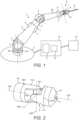
- Figure 1 shows a surgical robot having an arm 1 which extends from a base 2.
- the arm comprises a number of rigid limbs 3.
- the limbs are coupled by revolute joints 4.
- the most proximal limb 3a is coupled to the base by joint 4a. It and the other limbs are coupled in series by further ones of the joints 4.
- a wrist 5 is made up of four individual revolute joints.
- the wrist 5 couples one limb (3b) to the most distal limb (3c) of the arm.
- the most distal limb 3c carries an attachment 8 for a surgical instrument or tool 9.
- Each joint 4 of the arm has one or more motors 6 which can be operated to cause rotational motion at the respective joint, and one or more position and/or torque sensors 7 which provide information regarding the current configuration and/or load at that joint.
- motors 6 which can be operated to cause rotational motion at the respective joint
- position and/or torque sensors 7 which provide information regarding the current configuration and/or load at that joint.
- the arm may be generally as described in our co-pending patent application PCT/GB2014/053253 , published as WO 2015/132549 A1 .
- the attachment point 8 for a tool can suitably comprise any one or more of: (i) a formation permitting a tool to be mechanically attached to the arm, (ii) an interface for communicating electrical and/or optical power and/or data to and/or from the tool, and (iii) a mechanical drive for driving motion of a part of a tool.
- the motors are arranged proximally of the joints whose motion they drive, so as to improve weight distribution.
- controllers for the motors, torque sensors and encoders are distributed with the arm. The controllers are connected via a communication bus to control unit 10.
- a control unit 10 comprises a processor 11 and a memory 12.
- Memory 12 stores in a non-transient way software that is executable by the processor to control the operation of the motors 6 to cause the arm 1 to operate in the manner described herein.
- the software can control the processor 11 to cause the motors (for example via distributed controllers) to drive in dependence on inputs from the sensors 7 and from a surgeon command interface 13.
- the control unit 10 is coupled to the motors 6 for driving them in accordance with outputs generated by execution of the software.
- the control unit 10 is coupled to the sensors 7 for receiving sensed input from the sensors, and to the command interface 13 for receiving input from it.
- the respective couplings may, for example, each be electrical or optical cables, or may be provided by a wireless connection.
- the command interface 13 comprises one or more input devices whereby a user can request motion of the arm in a desired way.
- the input devices could, for example, be manually operable mechanical input devices such as control handles or joysticks, or contactless input devices such as optical gesture sensors.
- the software stored in memory 12 is configured to respond to those inputs and cause the joints of the arm to move accordingly, in compliance with a predetermined control strategy.
- the control strategy may include safety features which moderate the motion of the arm in response to command inputs.
- a surgeon at the command interface 13 can control the robot arm 1 to move in such a way as to perform a desired surgical procedure.
- the control unit 10 and/or the command interface 13 may be remote from the arm 1.
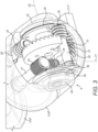
- FIG. 2 shows the wrist 5 of the robot in more detail.
- the wrist comprises four revolute joints 300, 301, 302, 303.
- the joints are arranged in series, with a rigid part of the arm extending from each joint to the next.
- the most proximal joint 300 of the wrist joins arm part 4b to arm part 310.
- Joint 300 has a "roll" rotation axis 304, which is directed generally along the extent of the limb 4b of the arm that is immediately proximal of the articulations of the wrist.
- the next most distal joint 301 of the wrist joins arm part 310 to arm part 311.
- Joint 301 has a "pitch" rotation axis 305 which is perpendicular to axis 304 in all configurations of joints 300 and 301.
- Joint 302 joins arm part 310 to arm part 311.
- Joint 302 has a "yaw” rotation axis 306 which is perpendicular to axis 305 in all configurations of joints 301 and 302. In some configurations of the wrist, axis 306 is also perpendicular to axis 304.
- the next most distal joint of the wrist 303 joins arm part 311 to arm part 4c.
- Joint 303 has a "roll” rotation axis 307 which is perpendicular to axis 306 in all configurations of joints 302 and 303.
- axis 307 is also perpendicular to axis 305 and parallel with (and preferably collinear with) axis 304. It is preferable for axes 305 and 306 to intersect each other, since this gives a particularly compact configuration. Joints 300 and 303 may be positioned so that axes 304 and 307 can pass through the intersection of axes 305, 306 for some configurations of the wrist.
- This design of wrist is advantageous in that it allows a wide range of movement from a tool attached to the attachment point 8 at the distal end of arm part 4c, but with the wrist being capable of being assembled in a relatively compact form and without there being singularities at certain parts of the range of motion that could demand excessively high rates of motion at individual joints.
- Figures 3 and 4 show one example of a mechanism suitable for implementing part of the wrist 5 of the arm 1 of figure 1 .
- Figures 3 and 4 concentrate (as to figures 5 to 10 ) on the mechanism associated with the joints designated 301 and 302 in figure 2 .
- the rigid arm parts 310, 311 have hollow outer shells or casings 310', 310", 311'.
- the shells define the majority of the exterior surface of the arm, and include a void which is partly or fully encircled by the exterior wall of the respective shell and within which the motors, sensors, cables and other components of the arm can be housed.
- the shells could be formed of a metal, for example an aluminium alloy or steel, or from a composite, for example a fibre-reinforced resin composite such as carbon fibre reinforced resin.
- the shells constitute part of the rigid structure of the arm parts that attaches between the respective joints.
- the shells may contain a structural framework as shown later in relation to the embodiment of figure 7 .
- the shell of arm part 310 is shown in two parts: 310' and 310", both of which are drawn in outline and exploded from each other.
- the shells of arm parts 4b and 4c are omitted, as is the mechanism associated with joints 300 and 303.
- the shell of arm part 311 is shown in part, the majority extending from spur 311'.
- the shell of arm part 310 (constituted by shell parts 310' and 310") and the shell of arm part 311 (which extends from spur 311') are movable with respect to each other about two rotation axes, shown at 20 and 21. These correspond to axes 305, 306 of figure 2 .
- Axes 20 and 21 are orthogonal.
- Axes 20 and 21 intersect.
- a central coupler 28 is mounted to arm part 310 by bearings 29, 30.
- the coupler extends between the bearings 29, 30.
- the bearings 29, 30 hold the coupler fast with arm part 310 except that they permit relative rotation of the coupler and that arm part about axis 20, thus defining a revolute joint corresponding to joint 301 of figure 2 .
- a further bearing 31 attaches the distal shell connector spur 311' to the coupler 28.
- Bearing 31 holds the distal shell connector spur 311' fast with the coupler 28 except for permitting relative motion of the spur and the coupler about axis 21, thus defining a revolute joint corresponding to joint 302 of figure 2 .
- coupler 28 is fast with the arm part 310 about axis 21.
- Coupler 28 is also fast with the arm part 311 about axis 20. That is, the mechanism is arranged so that coupler 28 and arm part 310 cannot undergo relative rotation or motion about axis 21; and coupler 28 and arm part 311 cannot undergo relative rotation or motion about axis 20.
- Two electric motors 24, 25 are mounted in arm part 310.
- the motors drive respective drive shafts 26, 27 which extend into the midst of the wrist mechanism.
- Shaft 26 drives rotation about axis 20.
- Shaft 27 drives rotation about axis 21.
- Drive shaft 26 terminates at its distal end in a worm gear 32.
- the worm gear 32 engages a bevel gear 33 which is fast with the coupler 28.
- Drive shaft 27 terminates at its distal end in a worm gear 34.
- the worm gear 34 engages a gear train shown generally at 35 which terminates in a further worm gear 36.
- Worm-form pinion gear 36 engages a hypoid-toothed bevel gear 37 which is fast with the distal shell connector 311'.
- the gear 33 is directly attached to the coupler 28. That is, the coupler 28 abuts the gear 33. Gear 33 is therefore mounted to the coupler 28.
- the distal shell connector spur 311' is also directly attached to the gear 37. Thus the gear 37 may abut the connector spur 311'.
- Shafts 26 and 27 are parallel. They both extend along the arm part 310.
- shafts 26 and 27 extend in a direction substantially parallel to the longitudinal direction of the arm part 310.
- the shafts could be parallel to the longitudinal direction of the arm part 310, or they could be mounted at an angle to the general longitudinal direction of the arm part 310.
- the arm part 310 may taper in the direction from the proximal end towards the distal end, and the shafts 26 and 27 may extend in a direction that is parallel to the taper angle of the arm part.
- Worms 32 and 34 are attached to the drive shafts 26 and 27 respectively and so may be referred to as shaft gears.
- Rotation of gear 33 drives rotation of arm part 311 relative to arm part 310 about axis 20, and thus gear 33 may be referred to as a drive gear.
- rotation of gear 37 drives rotation of arm part 311 relative to arm part 310 about axis 21, and thus gear 37 may also be referred to as a drive gear.
- Gear 33 is formed as a sector gear: that is its operative arc (defined in the example of figures 3 and 4 by the arc of its teeth) is less than 360°.
- the gear train 35 is borne by the coupler 28.
- the gear train comprises an input gear 38 which engages the worm 34.
- Input gear 38 is located with its rotation axis relative to the coupler 28 being coincident with axis 20. That means that the input gear can continue to engage the worm 34 irrespective of the configuration of the coupler 28 relative to arm part 310 about axis 20.
- a series of further gears whose axes are parallel with axis 20 transfer drive from the input gear 38 to an output gear 39 on a shaft 40 whose rotation axis relative to the carrier 28 is parallel with but offset from axis 20.
- Shaft 40 terminates in the worm 36.
- Shaft 40 extends parallel to axis 20.
- the gears of gear train 35, together with shaft 40, are borne by the coupler 28.
- motor 24 is operated to drive shaft 26 to rotate relative to arm part 310.
- This drives the bevel gear 33 and hence coupler 28 and distal shell spur 311' to rotate about axis 20 relative to arm part 310.
- motor 25 is operated to drive shaft 27 to rotate relative to arm part 310.
- This drives the bevel gear 37 and hence distal shell connector 311' to rotate about axis 21 relative to arm part 310.
- control system 10 of the arm is configured so that when required there is compensatory motion of drive shaft 27 in tandem with motion of drive shaft 26 so as to isolate motion about axis 21 from motion about axis 20. For example, if it is required to cause relative motion of shells 310, 311 about only axis 20 then motor 24 is operated to cause that motion whilst motor 25 is simultaneously operated in such a way as to prevent input gear 38 from rotating relative to carrier 28.
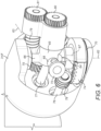
- Figures 5 and 6 show a second form of wrist mechanism , which is not part of the present invention, suitable for providing joints 301, 302 in a wrist of the type shown in figure 2 .
- the wrist comprises a pair of rigid external shells 310', 311' which define the exterior surfaces of arm parts 310, 311 respectively of figure 2 .
- 310' is the more proximal of the shells.
- the arm parts formed of the shells 310', 311' can pivot relative to each other about axes 62, 63, which correspond respectively to axes 305, 306 of figure 2 .
- Axes 62, 63 are orthogonal. Axes 62, 63 intersect.
- the shells 310', 311' define the exterior of the arm in the region of the wrist and are hollow, to accommodate a rotation mechanism and space for passing cables etc., as will be described in more detail below.
- the shells could be formed of a metal, for example an aluminium alloy or steel, or from a composite, for example a fibre-reinforced resin composite such as carbon fibre.
- the shells constitute the principal rigid structure of the arm parts that attaches between the respective joints.
- Figure 6 shows the same mechanism from distally and one side, with the shell 311' removed for clarity.
- Shell 310' is coupled to shell 311' by a cruciform coupler 64.
- the coupler has a central tube 65 which defines a duct through its centre, running generally along the length of the arm. Extending from the tube are first arms 66, 67 and second arms 68, 69.
- Each of the shells 310', 311' is attached to the coupler 64 by a revolute joint: i.e. in such a way that it is confined to be able to move relative to the coupler only by rotation about a single axis.
- the first arms 66, 67 attach to shell 310' by bearings 70, 71 which permit rotation between those first arms and the shell 310' about axis 62.
- the second arms 68, 69 attach to shell 311' by bearings 72, 73 which permit rotation between those second arms and the shell 311' about axis 63.
- a first bevel gear 74 is concentric with the first arms 66, 67. The first bevel gear is fast with the coupler 64 and rotationally free with respect to the proximal one of the two shells 310'.
- a second bevel gear 75 is concentric with the second arms 68, 69. The second bevel gear is fast with the distal one of the two shells 311' and rotationally free with respect to the coupler 64.
- the pair of arms 66, 67 of the coupler are perpendicular to the pair of arms 68, 69. Arms 66 and 67 lie on the rotation axis 62; and arms 68 and 69 lie on the rotation axis 63.
- the coupler 64 is directly attached to the gear 74. Thus the coupler 64 abuts gear 74. Coupler 64 (and hence gear 74) can rotate relative to the arm part 310 about axis 62. However, the coupler 64 and gear 74 are fast with the arm part 310 about the axis 63 such that there can be no relative motion or rotation between the coupler 64 and arm part 310 about axis 63.
- the bevel gear 75 may be mounted directly to the arm part 311.
- the bevel gear 75 can rotate with respect to the coupler 64 (and hence arm part 310) about axis 63.
- the gear 75 is fast with the coupler 64 about axis 62. That is, there can be no relative rotation or motion between coupler 64 and gear 75 about axis 62.
- Two shafts 76, 77 operate the motion of the compound joint.
- the shafts extend into the central region of the joint from within the proximal one of the shells 310'.
- Each shaft is attached at its proximal end to the shaft of a respective electric motor (not shown), the housings of the motors being fixed to the interior of the proximal shell 310'. In this way the shafts 76, 77 can be driven by the motors to rotate with respect to the proximal shell 310'.
- Shaft 76 and its associated motor operate motion about axis 62.
- Shaft 76 terminates at its distal end in a worm gear 78 which engages bevel gear 74.
- Rotation of shaft 76 causes rotation of the bevel gear 74 relative to shell 310' about axis 62.
- Bevel gear 74 is fast with the coupler 64, which in turn carries the distal shell 311'.
- rotation of shaft 76 causes relative rotation of the shells 310', 311' about axis 62.
- Shaft 77 and its associated motor operate motion about axis 63.
- bevel gear 75 By means of a worm gear 79 carried by the coupler 64.
- Rotation of that worm gear can cause relative rotation of the coupler and the distal shell 311'.
- drive is transmitted from the shaft 77 through a pair of gears 80, 81 borne by the carrier 64 to a shaft bearing the worm gear 79.
- Shaft 77 approaches the carrier 64 from the proximal side.
- the gears 80, 81 are located on the distal side of the coupler. Gears 80, 81 and 79 are thus fast with the coupler 64 about axes 62 and 63.
- the shaft 77 passes through the duct defined by tube 65 in the centre of the coupler.
- the shaft 77 has a universal or Hooke's joint 82 along its length.
- the universal joint 82 lies on axis 62.
- the shaft could have another form of flexible coupling, for example an elastic coupling (which could be integral with the shaft) or a form of constant velocity joint.
- Worm 78 is attached to drive shaft 76 and so may be referred to as a shaft gear.
- Rotation of gear 74 drives rotation of the arm part 311 relative to the arm part 310 about axis 62, and thus gear 74 may be referred to as a drive gear.
- rotation of gear 75 drives rotation of arm part 311 relative to arm part 310 about axis 63, and so gear 75 may also be referred to as a drive gear.
- Shaft 77 traverses a plane that contains rotation axis 63.
- the plane additionally contains rotation axis 62.
- the shaft 77 comprises a proximal portion that is proximal of that plane, and a distal portion that is distal of that plane.
- the proximal portion of the shaft 77 is attached or otherwise coupled to the motor.
- the distal portion of the shaft attaches to the gear 80.
- Gear 80 is therefore located on the distal side of that plane.
- Gear 80 may also be referred to as a shaft gear.
- the proximal and distal portions of the shaft 77 may be separated by the Hooke's joint 82.
- the Hooke's joint permits the proximal and distal portions of the shaft 77 to rotate with each other such that rotation of the proximal portion is coupled to the distal portion. Since the distal portion of shaft 77 is attached to gear 80, it follows that gear 80 is rotationally fast with shaft 77.
- Gear 80 engages, or meshes with, gear 81.
- gears 80 and 81 are spur gears.
- Gears 80 and 81 have parallel but offset rotation axes.
- the rotation axis of gear 80 is collinear with the rotation axis of the distal portion of shaft 77.
- Worm 79 is arranged to rotate in response to a rotation of gear 81.
- Worm 79 may be rotationally fast with gear 81 such that a rotation of gear 81 causes a corresponding rotation of worm 79.
- Worm 79 may have a rotation axis that is collinear with the rotation axis of gear 81.
- gears 80 and 81 operate to couple rotation of shaft 77 to rotation of gear 79 about a rotation axis parallel to the rotation axis of the distal portion of shaft 77.
- gear 75 is therefore a skew-axis gear.
- gear 74 is also a skew-axis gear.
- Any such parasitic rotation of the Hooke's joint may cause a consequent rotation of gears 80 and 81, and thus rotation of the bevel gear 75.
- Such parasitic motion may be prevalent if the hinge axes of the Hooke's joint are not perpendicular to each other, and/or if one of the hinge axes is not parallel and coincident with the rotation axis 62.
- control system 10 may be configured to drive compensatory motion of the shaft 77 in tandem with motion of the shaft 76 so as to isolate motion about axis 62 from motion about axis 63.
- control system 10 may be arranged to operate the motor to drive rotation of shaft 76 to cause rotation of arm part 311' relative to arm part 310' about axis 63 whilst simultaneously operating the motor to drive shaft 77 to rotate in such a way as to prevent parasitic rotation about axis 63.
- the control system 10 may be configured to operate in this manner when the robot arm is commanded to articulate about axis 62 without articulating about axis 63.
- the control system 10 may also be configured to drive rotation of shafts 76 and/or 77 in such a way as to reduce irregularities (i.e. increase smoothness) in the rotation of the Hooke's joint 82.
- the Hooke's joint may experience irregularities in its rotation when it is off axis, i.e. when arm part 311' is pitched relative to arm part 310' about axis 62.
- the control system may operate to drive the rotation of shaft 77 in such a way as to maintain a smooth or consistent rotation speed of the Hooke's joint 82. This may help to provide a smooth and/or consistent rotation about axis 63.
- This mechanism has been found to be capable of providing a particularly compact, light and rigid drive arrangement for rotation about axes 62 and 63 without the components of the mechanism unduly restricting motion of the shells. It permits both motors to be housed in the proximal shell which reduces distal weight.
- Figures 7 to 10 illustrate another form of wrist mechanism, which is not part of the present invention.
- the shells of arm parts 310, 311 are omitted, exposing the structure within the arm parts.
- Proximal arm part 310 has a structural framework 100, which is shown in outline in some of the figures.
- Distal arm part 311 has a structural framework 101.
- Arm parts 310 and 311 are rotatable relative to each other about axes 102, 103, which correspond to axes 305, 306 respectively of figure 2 .
- a carrier 104 couples the arm parts 310, 311 together.
- Carrier 104 is attached by bearings 105, 190 to arm part 310.
- bearings define a revolute joint about axis 102 between arm part 310 and the carrier 104.
- Carrier 104 is attached by bearing 106 to arm part 311.
- Those bearings define a revolute joint about axis 103 between arm part 311 and the carrier 104.
- a first bevel gear 107 about axis 102 is fast with the carrier 104.
- a second bevel gear 108 about axis 103 is fast with arm part 311.
- the carrier 104 can therefore rotate relative to the arm part 310 about axis 102.
- the carrier 104 is otherwise fast with the arm part 310 and in particular is fast about axis 103.
- the second bevel gear 108 can rotate relative to the carrier 104 about axis 103.
- the second bevel gear 108 (and hence the arm part 311) may be fast with the carrier about axis 102.
- the second bevel gear 108 is permitted to undergo relative rotation with respect to the carrier 104 about axis 103 but is not permitted to undergo relative rotation with respect to the carrier about axis 102.
- Axes 102 and 103 are in this example perpendicular, but in general are two non-parallel axes. They may be substantially orthogonal to each other.
- the axes are substantially transverse to the longitudinal direction of the arm part 310 in at least one configuration of the joints 301 and 302. In the arrangement shown, one such configuration is when arm part 311 is not articulated with respect to arm part 310.
- axis 102 may be considered as a "pitch" rotation axis and axis 103 as a "yaw” rotation axis.
- the carrier 104 is located inboard of the limbs 310, 311.
- Two motors 109, 110 are fixed to the framework 100 of arm part 310.
- Motor 109 drives a shaft 111.
- Shaft 111 is rigid and terminates in a worm 118 which engages bevel gear 107.
- shaft 111 rotates relative to the proximal arm part 310, driving bevel gear 107 and hence coupler 104 and arm part 311 to rotate relative to arm part 310 about axis 102.
- Motor 110 drives a shaft 112.
- Shaft 112 has a worm 113 near its distal end which engages bevel gear 108.
- shaft 112 To accommodate motion of bevel gear 108 relative to motor 110 when the coupler 104 moves about axis 102 shaft 112 includes a pair of universal joints 114, 115 and a splined coupler 116 which accommodates axial extension and retraction of shaft 112. The final part of shaft 112 is mounted to the coupler 104 by bearing 117.
- the splined coupler 116 is an example of a prismatic joint.
- the distal part of the shaft 112 that is mounted to the carrier 104 by bearing 117 is fast with the worm 113 (shown most clearly in figure 10 ).
- the bearing 117 defines a revolute joint located on the opposite side of the universal joint 115 to the coupler 116. This revolute joint permits the distal part of the shaft 112 to rotate relative to the carrier 104.
- the distal part of the shaft 112 extends in a direction perpendicular to the axis 102 in all rotational positions of the carrier, and is rotatable with respect to the carrier 104 about an axis perpendicular to axis 102.
- the shaft 112 traverses a plane containing axis 102 that is transverse to the longitudinal direction of the arm part 310.
- the distal part of the shaft 112 is directly attached to the worm 113 and so extends between the worm and the carrier 104.
- the distal part of the shaft 112 is mounted to the carrier 104 so as to securely engage the worm 113 with the bevel gear 108 when the carrier 104 is articulated about the axis 102.
- the universal joints 114 and 115 of shaft 112 are located on opposing sides of the coupler 116. Both universal joints are located proximally of the rotation axes 102 and 103.
- the universal joints 114, 115 and the coupler 116 are arranged to permit the carrier 104 to rotate relative to arm part 310 about axis 102.
- Bevel gear 107 is disposed about axis 102. That is, gear 107 has as its rotation axis the axis 102. The rotation of gear 107 about axis 102 drives rotation of the arm part 311 relative to the arm part 310. Gear 107 may therefore be referred to as a drive gear.
- Bevel gear 108 is disposed about axis 103.
- bevel gear 108 has as its rotation axis the axis 103.
- the rotation of gear 108 about axis 103 drives rotation of the arm part 311 relative to the arm part 310 about axis 310.
- Gear 108 may therefore also be referred to as a drive gear.
- Shaft 111 extends along the longitudinal direction of the arm part 310.
- the longitudinal axis of shaft 111 may be perpendicular to axis 102 in all rotational positions of the carrier 104 about axes 102 and 103.
- the shaft 111 (and the affixed worm 118) rotate about the longitudinal axis of the shaft 111.
- This rotation axis is non-parallel and non-intersecting with the rotational axis 102 of the gear 107.
- Gear 107 is therefore a skew axis gear.
- Both worms 113 and 118 may be located on a single side of a plane containing axis 103 that is transverse to the longitudinal direction of the arm part 311 when that arm part is aligned with arm part 310 about axis 103, in other words when arm part 311 is not in yaw relative to arm part 310.
- both worms may be located on the proximal side of that plane.
- the worms 113 and 118 may be located on opposing sides of a plane containing axis 102 that is parallel to the longitudinal direction of the arm part 311.
- the worm gears 113 and 118 undergo rotation with respect to each other about axis 102 when the carrier 104 is articulated about axis 102.
- arm part 310 is aligned with arm part 311 about axis 102 (i.e., when arm part 311 is not in pitch relative to arm part 310)
- worm gear 113 and the distal part of shaft 112 are parallel to worm gear 118 and shaft 111.
- worm gear 113 and the distal part of shaft 112 are non-parallel to worm gear 118 and shaft 111.
- Worms 113 and 118 are each attached to respective drive shafts 112 and 111 and so may be referred to as shaft gears.
- motor 109 is operated to rotate the drive shaft 111 about its longitudinal axis. Because the shaft gear 118 is attached to the shaft 111, rotation of shaft 111 causes gear 118 to also rotate about the longitudinal axis of the shaft 111. Shaft gear 118 engages the drive gear 107, causing it to rotate about axis 102 relative to the arm part 310. Carrier 104 is fast with the drive gear 107, and thus rotation of drive gear 107 causes carrier 104 to rotate about axis 102 relative to arm part 310. The rotation of carrier 104 about axis 102 drives the articulation of arm part 311 relative to arm part 310 about axis 102. Rotation of the carrier 104 about axis 102 causes articulations of universal joints 114 and 115 and the prismatic joint 116 to accommodate the rotation of shaft gear 113 relative to shaft gear 118 about axis 102.
- motor 110 is operated to rotate the drive shaft 112.
- Rotation of the proximal end of drive shaft 112 is coupled to the rotation of the shaft gear 113 via the universal joints 114 and 115 (and the coupler 116).
- Shaft gear 113 engages the bevel gear 108.
- rotation of shaft gear 113 drives rotation of gear 108 about axis 103 relative to the carrier 104.
- Bevel gear 108 is fast with the arm part 311, and thus rotation of gear 108 causes arm part 311 to be articulated with respect to arm part 310 about axis 103.
- control system 10 may be arranged to operate the motor 109 to drive rotation of shaft 111 to cause the rotation of arm part 311 relative to arm part 310 about axis 102 whilst simultaneously operating the motor 110 to drive rotation of shaft 112 in such a way as to prevent parasitic rotation about axis 103.
- the control system 10 may be configured to operate in this manner when the robot arm is commanded to articulate about axis 102 without articulating about axis 103.
- Control system 10 may also be configured to drive rotation of shaft 112 in such a way as to reduce irregularities in the rotation of universal joints 114 and 115.
- the Hooke's joints may experience irregular or inconsistent rotation when they are off-axis., i.e. when arm part 311 is in pitch relative to arm part 310.
- the control system 10 may operate to drive the rotation of shaft 112 in such a way as to maintain a smooth or consistent rotation speed of the Hooke's joints 114 and 115. This may help to provide a smooth and/or consistent rotation about axis 103.
- bevel gear 107 it is convenient for bevel gear 107 to be of part-circular form: i.e. its teeth do not encompass a full circle.
- gear 107 may encompass less than 270° or less than 180° or less than 90°. This allows at least part of the other bevel gear 108 to be located in such a way that it intersects a circle coincident with gear 107, about the axis of gear 107 and having the same radius as the outermost part of gear 107.
- bevel gear 107 may be interposed between the worms 113 and 118. This may help to provide a compact packaging arrangement.
- the gears 107 and/or 108 are conveniently provided as bevel gears since that permits them to be driven from worms located within the plan of their respective external radii. However, they could be externally toothed gears engaged on their outer surfaces by the worms attached to shafts 111, 112, or by externally toothed gears.
- the bevel gears and the worm gears that mate with them can conveniently be of skew axis, e.g. Spiroid ® , form. These allow for relatively high torque capacity in a relatively compact form.
- each joint is provided with a torque sensor which senses the torque applied about the axis of that joint. Data from the torque sensors is provided to the control unit 10 for use in controlling the operation of the arm.
- Torque sensor 150 measures the torque applied about axis 103: that is from carrier 104 to distal arm frame 101.
- bevel gear 108 is fast with frame 101 and rotatable about axis 103 with respect to the carrier 104.
- Bevel gear 108 comprises a radially extending gear portion 151, from which its gear teeth 152 extend in an axial direction, and an axially extending neck 153.
- the neck, the radially extending gear portion and the teeth are integral with each other.
- the interior and exterior walls of the neck 153 are of circularly cylindrical profile.
- a pair of roller or ball bearing races 106, 154 fit snugly around the exterior of the neck. The bearings sit in cups in the carrier 104 and hold the neck 153 in position relative to the carrier whilst permitting rotation of the bevel gear 108 relative to the carrier about axis 103.
- the torque sensor 150 has a radially extending top flange 155, an axially elongate torsion tube 156 which extends from the top flange, and an internally threaded base 157 at the end of the torsion tube opposite the flange.
- the top flange 155 abuts the gear portion 151 of the bevel gear 108.
- the top flange is held fast with the gear portion by bolts 158.
- the torsion tube 156 extends inside the neck 153 of the bevel gear 108.
- the exterior wall of the torsion tube is of circularly cylindrical profile.
- the exterior of the base 157 is configured with a splined structure which makes positive engagement with a corresponding structure in the frame 101 so as to hold the two in fixed relationship about axis 103.
- a bolt 159 extends through the frame 101 and into the base 157 to clamp them together.
- the torsion tube has a hollow interior and a relatively thin wall to its torsion tube 150. When torque is applied through the torque sensor there is slight torsional distortion of the torsion tube. The deflection of the torsion tube is measured by strain gauges 160 fixed to the interior wall of the torsion tube.
- the strain gauges form an electrical output indicative of the torsion, which provides a representation of the torque about axis 103.
- the strain gauges could be of another form: for example optical interference strain gauges which provide an optical output.
- a sleeve or bushing 161 is provided around the torsion tube 156 and within the neck 153 of the bevel gear 108.
- the sleeve is sized so that it makes continuous contact with the interior wall of the neck 153 and with the exterior wall of the torsion tube 156, which is also of circularly cylindrical profile. The whole of the interior surface of the sleeve makes contact with the exterior of the torsion tube 156.
- the whole of the exterior surface of the sleeve makes contact with the interior surface of the neck 153.
- the sleeve is constructed so that it applies relatively little friction between the neck and the torsion tube: for instance the sleeve may be formed of or coated with a low-friction or self-lubricating material.
- the sleeve is formed of a substantially incompressible material so that it can prevent deformation of the torque sensor under shear forces transverse to the axis 103.
- the sleeve may be formed of or coated with a plastics material such as nylon, polytetrafluoroethylene (PTFE), polyethylene (PE) or acetal (e.g. Delrin ® ), or of graphite or a metal impregnated with lubricant.
- the interior wall of the neck 153 of the bevel gear 108 is stepped inwards at 162, near its end remote from the radially extending gear portion 151.
- the sleeve 161 is located between the neck 153 and the torsion tube 156, and the head 155 of the torque sensor is bolted to the gear portion 151 the sleeve is held captive both radially (between the torsion tube and the neck) and axially (between the head 155 of the torque sensor and the step 162 of the interior surface of the neck 153 of the bevel gear).
- the internal radius of the neck 153 in the region 163 beyond the step 162 is such that the internal surface of the neck in that region is spaced from the torque sensor 150, preventing frictional torque transfer between the two.
- Hall effect sensors are used to sense the rotational position of the joints.
- Each position sensor comprises a ring of material arranged around one of the rotation axes.
- the ring has a series of regularly spaced alternating north and south magnetic poles.
- Adjacent to the ring is a sensor chip with a sensor array comprising multiple Hall effect devices which can detect the magnetic field and measure the position of the magnetic poles on the ring relative to the sensor array so as to provide a multi-bit output indicative of that relative position.
- the rings of magnetic poles are arranged such that each position of the respective joint within a 360° range is associated with a unique set of outputs from the pair of magnetic sensors. This may be achieved by providing different numbers of poles on each ring and making the numbers of poles the rings co-prime to each other. Hall effect position sensors employing this general principle are known for use in robotics and for other applications.
- each joint associated with each joint is a pair of alternatingly magnetised rings, and associated sensors.
- Each ring is arranged concentrically about the axis of its respective joint.
- the rings are fast with an element on one side of the joint and the sensors are fast with an element on the other side of the joint, with the result that there is relative rotational motion of each ring and its respective sensor when there is rotation of the robot arm about the respective joint.
- Each individual sensor measures where between a pair of poles the associated ring is positioned relative to the sensor. It cannot be determined from the output of an individual sensor which of the pole pairs on the ring is above the sensor. Thus the individual sensors can only be used in a relative fashion and would require calibration at power up to know the absolute position of the joint.
- a pair of rings designed so that the numbers of pole pairs in each ring has no common factors it is possible to combine the inter-pole pair measurement from both sensors and work out the absolute position of the joint without calibration.
- Magnetic rings and sensors are shown in figures 7 to 10 .
- For the joint that provides rotation about axis 102 position is sensed by means of magnetic rings 200 and 201 and sensors 202 and 203.
- For the joint that provides rotation about axis 103 position is sensed by means of magnetic rings 210, 211, sensor 212 and a further sensor that is not shown.
- Magnetic ring 200 is fast with carrier 104 and mounted on one side of the carrier.
- Magnetic ring 201 is fast with carrier 104 and mounted on the other side of the carrier to magnetic ring 200.
- the magnetic rings 200, 201 are planar, and arranged perpendicular to and centred on axis 102.
- Sensors 202 and 203 are fast with the frame 100 of the arm part 310.
- Sensor 202 is mounted so as to be adjacent to a side of ring 200.
- Sensor 203 is mounted so as to be adjacent to a side of ring 201.
- Cables 204, 205 carry the signals from the sensors 202, 203.
- Magnetic ring 210 is fast with carrier 104 and mounted on one side of a flange 220 of the carrier.
- Magnetic ring 211 is fast with carrier 104 and mounted on the other side of the flange 220 to magnetic ring 200.
- the magnetic rings 210, 211 are planar, and arranged perpendicular to and centred on axis 103.
- Sensor 212 and the other sensor for rotation about axis 103 are fast with the frame 101 of the arm part 311.
- Sensor 212 is mounted so as to be adjacent to a side of ring 210.
- the other sensor is mounted so as to be adjacent to a side of ring 211.
- rotation about each of the axes 102, 103 is sensed by means of two multipole magnetic rings, each with a respective associated sensor.
- Each sensor generates a multi-bit signal representing the relative position of the nearest poles on the respective ring to the sensor.
- the outputs of the sensors are in combination indicative of the configuration of the joint within a 360° range. This permits the rotation position of the joint to be detected within that range.
- the two rings associated with each joint i.e.
- rings 200, 201 on the one hand and rings 210, 211 on the other hand) are located so as to be substantially offset from each other along the axis of the respective joint.
- Ring 200 is located near the bearing 190 on one side of the body of carrier 104 whereas ring 201 is located near bearing 105 on the opposite side of the carrier 104.
- Ring 210 is located on one side of the flange 220 whereas ring 211 is located on the other side of the flange 220.
- Each ring is made of a sheet of material which is flat in a plane perpendicular to the axis about which the ring is disposed.
- the magnetic rings of each pair i.e.
- rings 200, 201 on the one hand and rings 210, 211 on the other hand) are spaced from each other in the direction along their respective axes by a distance greater than 5 and more preferably greater than 10 or greater than 20 times the thickness of the rings of the pair.
- the rings of a pair can be on opposite sides of the respective joint, as with rings 200, 201.
- the carrier 104 to which the both rings of a pair are attached extends radially outwardly so as to lie at a radial location that is between the rings when viewed in a plane containing the respective rotation axis.
- flange 220 lies radially between rings 210 and 211.
- the respective joint can be supported or defined by two bearings, one on either side of the joint along the respective axis, and at extreme locations on the joint, and the or each ring for that joint can overlap a respective one of the bearings in a plane perpendicular to the axis.
- the sensors for the rings can be mounted on an arm part that is articulated by the joint. The sensors can be mounted on opposite sides of the arm part.
- the packaging of the joint and/or of the arm part where the associated sensors are mounted can be greatly improved. Spacing the rings apart allows for more opportunities to locate the rings at a convenient location, and allows the sensors to be spaced apart, which can itself provide packaging advantages. It is preferred that the joint is sufficiently stiff in comparison to the number of magnetic poles on the rings that torsion of the joint under load will not adversely affect measurement. For example it is preferred that the joint is sufficiently stiff that under its maximum rated operating load the elements of the joint cannot twist so much that it can cause a change in the order of magnetic transitions at the sensors, even though they are spaced apart. That permits direction to be detected, in addition to motion, for all load conditions.
- Arm part 311 is distal of arm part 310. Arm part 310 is proximal of the joint about axes 102 and 103 shown in figure 7 to 10 . As discussed with reference to figure 1 , data from the torque sensors and the position sensors to be fed back to the control unit 10. It is desirable for that data to be passed by wired connections that run through the arm itself.
- Each arm part comprises a circuit board.
- Figures 7 to 10 show a circuit board 250 carried by arm part 311.
- Each circuit board includes a data encoder/decoder (e.g. integrated circuit 251).
- the encoder/decoder converts signals between formats used locally to the respective arm part and a format used for data transmission along the arm. For example: (a) locally to the arm part the position sensors may return position readings as they are passed by magnetic pole transitions, the torque sensor may return an analogue or digital signal indicative of the currently sensed torque and the drive motors may require a pulse width modulated drive signal; whereas (b) for data transmission along the arm a generic data transmission protocol, which may be a packet data protocol such as Ethernet, can be used.
- a generic data transmission protocol which may be a packet data protocol such as Ethernet
- the encoders/decoders can receive data packets conveyed along the arm from the control unit 10 and interpret their data to form control signals for any local motor, and can receive locally sensed data and convert it into packetised form for transmission to the control unit.
- the circuit boards along the arm can be chained together by communication cables, so that communications from a relatively distal board go via the more proximal boards.
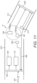
- the compound joint about axes 102, 103 has rotary position sensors 202, 203 (for rotation about axis 102) and 212 (for rotation about axis 103).
- Sensors 202, 203 are mounted on the frame 100 of the arm part 310 that is proximal of the joint whose motion is measured by the sensor. Data from position sensors 202, 203 is fed along cables 204, 205 which lead along arm part 310 proximally of the sensors.
- Sensor 202 is mounted on the frame 101 of the arm part 311. Data from position sensor 202 is fed along a cable to circuit board 250 on the same arm part. In each case the data is not passed to a more distal element of the arm than the one where the data was collected.
- the compound joint about axes 102, 103 has torque sensors 150 (for rotation about axis 103) and 191 (for rotation about axis 102).
- Data sensed by torque sensors 150, 191 is carried in native form to circuit board 250 by flexible cables.
- the encoder/decoder 251 encodes the sensed data, e.g. to Ethernet packets, and transmits it to the control unit 10.
- the data from the torque sensors is passed to the circuit board of the more distal arm part for encoding, and then from that circuit board it is passed by cables in a distal direction along the arm.
- Arm part 310 comprises circuit board 195 which receives data from position sensor 202 and provides command data to motors 109, 110.
- Arm part 311 comprises circuit board 250 which receives data from position sensor 212 and torque sensors 150, 191.
- Circuit board 250 encodes that sensed data and passes it over a data bus 196 to circuit board 195, which forwards it on towards control unit 10 via a link 197.
- Position sensor 202 is connected directly by a cable to circuit board 195.
- Position sensor 212 and torque sensors 150, 191 are connected directly by cables to circuit board 195.
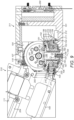
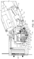
- FIG 12 shows a cross-section through a module that comprises arm part 4c.
- the module has a base 400 and a side-wall 440 which is fast with the base.
- Base 400 attaches to the end face 401 of the distal end of arm part 311. (See figure 7 ).
- Arm part 4c is indicated generally at 403.
- Arm part 4c is rotatable relative to the base about an axis 402 corresponding to axis 307 of figure 2 .
- arm part 4c is mounted to the side-wall 440 by bearings 430, 431 which define a revolute joint between side wall 440 and arm part 4c about axis 402.
- Arm part 4c has a housing 404 which houses its internal components. Those components include a circuit board 405 and motors 406, 407. Motors 406, 407 are fixed to the housing 404 so they cannot rotate relative to it. The housing 404 is free to rotate relative to the base 400 by means of the bearings 430, 431.
- a channel 408 runs through the interior of the module to accommodate a communication cable (not shown) passing from circuit board 250 to circuit board 405.
- the communication cable carries signals which, when decoded by an encoder/decoder of circuit board 405, cause it to issue control signals to control the operation of motors 406, 407.
- Motor 406 drives rotation of arm part 4c relative to arm part 311.
- motor 406 drives rotation of housing 404 relative to base 400.
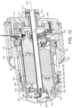
- Base 400 has a central boss 410.
- a torque sensor generally of the type discussed in relation to figures 9 and 10 is attached to the boss 410.
- the torque sensor has an integral member comprising a base 411, a torsion tube 412 and a radially extending head 413.
- the base 411 of the torque sensor is fast with the boss 410 of the base 400.
- a sleeve 421 extends around the torsion tube of the torque sensor to protect it from shear forces and to reduce friction between it and the surrounding component, which is the base 400.
- An internally toothed gear 420 is fast with the head 413 of the torque sensor.
- Motor 406 drives a shaft 414 which carries a pinion gear 415.
- Pinion gear 415 engages the internal gear 420.
- the motor 406 drives the pinion gear 415 to rotate and this causes the arm part 4c, of which the motor 406 is part, to rotate about axis 402.
- the resulting torque about axis 402 is transmitted to the base 400 through the torsion tube 412 of the torque sensor, allowing that torque to be measured by strain gauges attached to the torsion tube.
- the interface 8 for attachment to an instrument is shown in figure 12 .
- the shaft 440 of motor 407 is exposed at the interface for providing drive to an instrument.
- Torque data from the torque sensor 411, 412, 413 is passed to circuit board 250 on arm part 311 for encoding.
- the rotational position of arm part 4c can be sensed by a sensor 445 carried by arm part 4c and which detects transitions between magnetic poles on rings 446, 447 mounted on the interior of housing 404. Data from sensor 445 is passed to circuit board 405 of arm part 4c for encoding.
- the motors that drive rotation about joints 102 and 103 are mounted proximally of those joints, in arm part 310. As discussed above, this improves weight distribution by avoiding weight being placed nearer to the distal end of the arm. In contrast, the motor that drives rotation of arm part 4c is mounted in arm part 4c rather than in arm part 311. Although this might be seen as disadvantageous due to it requiring motor 406 to be mounted more distally, it has been found that this allows for arm part 311 to be especially compact. Motor 406 can be packaged in arm part 4c in parallel with the motor(s) (e.g. 407) which provide drive to the instrument: i.e. so that the motors intersect a common plane perpendicular to the axis 402. That means that incorporation of motor 406 in arm part 4c need not make arm part 4c substantially longer.
- the motor(s) e.g. 407
- the drive of the joints could be by frictional means.
Landscapes
- Engineering & Computer Science (AREA)
- Robotics (AREA)
- Mechanical Engineering (AREA)
- Health & Medical Sciences (AREA)
- Life Sciences & Earth Sciences (AREA)
- Surgery (AREA)
- General Engineering & Computer Science (AREA)
- Biomedical Technology (AREA)
- Nuclear Medicine, Radiotherapy & Molecular Imaging (AREA)
- Heart & Thoracic Surgery (AREA)
- Medical Informatics (AREA)
- Molecular Biology (AREA)
- Animal Behavior & Ethology (AREA)
- General Health & Medical Sciences (AREA)
- Public Health (AREA)
- Veterinary Medicine (AREA)
- Manipulator (AREA)
Applications Claiming Priority (2)
| Application Number | Priority Date | Filing Date | Title |
|---|---|---|---|
| GB1512959.6A GB2541369B (en) | 2015-07-22 | 2015-07-22 | Drive mechanisms for robot arms |
| PCT/GB2016/052264 WO2017013453A1 (en) | 2015-07-22 | 2016-07-22 | Drive mechanisms for robot arms |
Publications (2)
| Publication Number | Publication Date |
|---|---|
| EP3325224A1 EP3325224A1 (en) | 2018-05-30 |
| EP3325224B1 true EP3325224B1 (en) | 2024-10-23 |
Family
ID=54064809
Family Applications (1)
| Application Number | Title | Priority Date | Filing Date |
|---|---|---|---|
| EP16744496.7A Active EP3325224B1 (en) | 2015-07-22 | 2016-07-22 | Drive mechanisms for robot arms |
Country Status (7)
| Country | Link |
|---|---|
| US (4) | US10398516B2 (enExample) |
| EP (1) | EP3325224B1 (enExample) |
| JP (4) | JP6853813B2 (enExample) |
| CN (2) | CN114683312B (enExample) |
| DE (1) | DE202016009227U1 (enExample) |
| GB (3) | GB2541369B (enExample) |
| WO (1) | WO2017013453A1 (enExample) |
Families Citing this family (218)
| Publication number | Priority date | Publication date | Assignee | Title |
|---|---|---|---|---|
| US8807414B2 (en) * | 2006-10-06 | 2014-08-19 | Covidien Lp | System and method for non-contact electronic articulation sensing |
| US11090104B2 (en) | 2009-10-09 | 2021-08-17 | Cilag Gmbh International | Surgical generator for ultrasonic and electrosurgical devices |
| US9089353B2 (en) | 2011-07-11 | 2015-07-28 | Board Of Regents Of The University Of Nebraska | Robotic surgical devices, systems, and related methods |
| JP6502848B2 (ja) | 2011-10-03 | 2019-04-17 | ボード オブ リージェンツ オブ ザ ユニバーシティ オブ ネブラスカ | モジュール式手術用ロボットシステム |
| EP4357083A3 (en) | 2012-05-01 | 2024-08-21 | Board of Regents of the University of Nebraska | Single site robotic device and related systems and methods |
| US11871901B2 (en) | 2012-05-20 | 2024-01-16 | Cilag Gmbh International | Method for situational awareness for surgical network or surgical network connected device capable of adjusting function based on a sensed situation or usage |
| US20140005705A1 (en) * | 2012-06-29 | 2014-01-02 | Ethicon Endo-Surgery, Inc. | Surgical instruments with articulating shafts |
| US9408622B2 (en) | 2012-06-29 | 2016-08-09 | Ethicon Endo-Surgery, Llc | Surgical instruments with articulating shafts |
| US9393037B2 (en) | 2012-06-29 | 2016-07-19 | Ethicon Endo-Surgery, Llc | Surgical instruments with articulating shafts |
| CA2880622C (en) | 2012-08-08 | 2021-01-12 | Board Of Regents Of The University Of Nebraska | Robotic surgical devices, systems and related methods |
| US12295680B2 (en) | 2012-08-08 | 2025-05-13 | Board Of Regents Of The University Of Nebraska | Robotic surgical devices, systems and related methods |
| US9095367B2 (en) | 2012-10-22 | 2015-08-04 | Ethicon Endo-Surgery, Inc. | Flexible harmonic waveguides/blades for surgical instruments |
| CA2906672C (en) | 2013-03-14 | 2022-03-15 | Board Of Regents Of The University Of Nebraska | Methods, systems, and devices relating to force control surgical systems |
| CA2918531A1 (en) | 2013-07-17 | 2015-01-22 | Board Of Regents Of The University Of Nebraska | Robotic surgical devices, systems and related methods |
| GB201400569D0 (en) * | 2014-01-14 | 2014-03-05 | Randle Engineering Solutions Ltd | Articulation |
| US11504192B2 (en) | 2014-10-30 | 2022-11-22 | Cilag Gmbh International | Method of hub communication with surgical instrument systems |
| CA2967593C (en) | 2014-11-11 | 2024-02-27 | Board Of Regents Of The University Of Nebraska | Robotic device with compact joint design and related systems and methods |
| US20160217177A1 (en) * | 2015-01-27 | 2016-07-28 | Kabushiki Kaisha Toshiba | Database system |
| CN114027986B (zh) | 2015-08-03 | 2024-06-14 | 内布拉斯加大学董事会 | 机器人手术装置系统及相关方法 |
| US11134978B2 (en) | 2016-01-15 | 2021-10-05 | Cilag Gmbh International | Modular battery powered handheld surgical instrument with self-diagnosing control switches for reusable handle assembly |
| US11129670B2 (en) | 2016-01-15 | 2021-09-28 | Cilag Gmbh International | Modular battery powered handheld surgical instrument with selective application of energy based on button displacement, intensity, or local tissue characterization |
| US12193698B2 (en) | 2016-01-15 | 2025-01-14 | Cilag Gmbh International | Method for self-diagnosing operation of a control switch in a surgical instrument system |
| US11229471B2 (en) | 2016-01-15 | 2022-01-25 | Cilag Gmbh International | Modular battery powered handheld surgical instrument with selective application of energy based on tissue characterization |
| US10398439B2 (en) * | 2016-02-10 | 2019-09-03 | Covidien Lp | Adapter, extension, and connector assemblies for surgical devices |
| CN114098975A (zh) | 2016-05-18 | 2022-03-01 | 虚拟切割有限公司 | 机器人外科装置、系统及相关方法 |
| GB2552385B (en) | 2016-07-22 | 2021-09-15 | Cmr Surgical Ltd | Calibrating position sensor readings |
| GB2552478B (en) * | 2016-07-22 | 2021-04-28 | Cmr Surgical Ltd | Magnetic position sensor |
| CA3035064A1 (en) | 2016-08-30 | 2018-03-08 | Board Of Regents Of The University Of Nebraska | Robotic device with compact joint design and an additional degree of freedom and related systems and methods |
| US11266430B2 (en) | 2016-11-29 | 2022-03-08 | Cilag Gmbh International | End effector control and calibration |
| US11272929B2 (en) * | 2017-03-03 | 2022-03-15 | Covidien Lp | Dynamically matching input and output shaft speeds of articulating adapter assemblies for surgical instruments |
| USD873418S1 (en) * | 2017-05-30 | 2020-01-21 | Cmr Surgical Limited | Cart for surgical robot arm |
| USD896390S1 (en) | 2017-05-30 | 2020-09-15 | Cmr Surgical Limited | Console for controlling surgical robot |
| USD873417S1 (en) * | 2017-05-30 | 2020-01-21 | Cmr Surgical Limited | Surgical robot arm |
| CN107030729B (zh) * | 2017-06-14 | 2019-11-29 | 东北大学 | 一种仿人肘关节 |
| CN107260309B (zh) * | 2017-07-31 | 2021-05-07 | 成都博恩思医学机器人有限公司 | 手术机器人的手术器械和手术机器人 |
| CN107320188B (zh) * | 2017-07-31 | 2021-03-30 | 成都博恩思医学机器人有限公司 | 一种用于微创手术机器人的手术器械及微创手术机器人 |
| CN107334539B (zh) * | 2017-07-31 | 2021-04-13 | 成都博恩思医学机器人有限公司 | 手术机器人的手术器械和手术机器人 |
| WO2019050797A1 (en) * | 2017-09-05 | 2019-03-14 | Intuitive Surgical Operations, Inc. | SYSTEMS AND METHODS FOR COMPUTER-AIDED REMOTE CONTROL SURGERY |
| EP3687370B1 (en) | 2017-09-27 | 2024-11-20 | Virtual Incision Corporation | Robotic surgical devices with tracking camera technology and related systems |
| CN111556729B (zh) * | 2017-10-30 | 2023-09-15 | 爱惜康有限责任公司 | 包括自动夹具进给系统的外科施夹器 |
| US11229436B2 (en) | 2017-10-30 | 2022-01-25 | Cilag Gmbh International | Surgical system comprising a surgical tool and a surgical hub |
| US11801098B2 (en) | 2017-10-30 | 2023-10-31 | Cilag Gmbh International | Method of hub communication with surgical instrument systems |
| US11291510B2 (en) | 2017-10-30 | 2022-04-05 | Cilag Gmbh International | Method of hub communication with surgical instrument systems |
| US11311342B2 (en) | 2017-10-30 | 2022-04-26 | Cilag Gmbh International | Method for communicating with surgical instrument systems |
| US11510741B2 (en) | 2017-10-30 | 2022-11-29 | Cilag Gmbh International | Method for producing a surgical instrument comprising a smart electrical system |
| US11911045B2 (en) | 2017-10-30 | 2024-02-27 | Cllag GmbH International | Method for operating a powered articulating multi-clip applier |
| US11564756B2 (en) | 2017-10-30 | 2023-01-31 | Cilag Gmbh International | Method of hub communication with surgical instrument systems |
| US11317919B2 (en) | 2017-10-30 | 2022-05-03 | Cilag Gmbh International | Clip applier comprising a clip crimping system |
| US11413042B2 (en) | 2017-10-30 | 2022-08-16 | Cilag Gmbh International | Clip applier comprising a reciprocating clip advancing member |
| US11759224B2 (en) | 2017-10-30 | 2023-09-19 | Cilag Gmbh International | Surgical instrument systems comprising handle arrangements |
| JP6640821B2 (ja) * | 2017-11-24 | 2020-02-05 | ファナック株式会社 | ロボットの構造 |
| US20190201039A1 (en) | 2017-12-28 | 2019-07-04 | Ethicon Llc | Situational awareness of electrosurgical systems |
| US11571234B2 (en) | 2017-12-28 | 2023-02-07 | Cilag Gmbh International | Temperature control of ultrasonic end effector and control system therefor |
| US11857152B2 (en) | 2017-12-28 | 2024-01-02 | Cilag Gmbh International | Surgical hub spatial awareness to determine devices in operating theater |
| US11266468B2 (en) | 2017-12-28 | 2022-03-08 | Cilag Gmbh International | Cooperative utilization of data derived from secondary sources by intelligent surgical hubs |
| US11659023B2 (en) | 2017-12-28 | 2023-05-23 | Cilag Gmbh International | Method of hub communication |
| US10595887B2 (en) | 2017-12-28 | 2020-03-24 | Ethicon Llc | Systems for adjusting end effector parameters based on perioperative information |
| US20190201113A1 (en) | 2017-12-28 | 2019-07-04 | Ethicon Llc | Controls for robot-assisted surgical platforms |
| US11998193B2 (en) | 2017-12-28 | 2024-06-04 | Cilag Gmbh International | Method for usage of the shroud as an aspect of sensing or controlling a powered surgical device, and a control algorithm to adjust its default operation |
| US11602393B2 (en) | 2017-12-28 | 2023-03-14 | Cilag Gmbh International | Surgical evacuation sensing and generator control |
| US11832899B2 (en) | 2017-12-28 | 2023-12-05 | Cilag Gmbh International | Surgical systems with autonomously adjustable control programs |
| US11213359B2 (en) | 2017-12-28 | 2022-01-04 | Cilag Gmbh International | Controllers for robot-assisted surgical platforms |
| US10944728B2 (en) | 2017-12-28 | 2021-03-09 | Ethicon Llc | Interactive surgical systems with encrypted communication capabilities |
| US12096916B2 (en) | 2017-12-28 | 2024-09-24 | Cilag Gmbh International | Method of sensing particulate from smoke evacuated from a patient, adjusting the pump speed based on the sensed information, and communicating the functional parameters of the system to the hub |
| US11576677B2 (en) | 2017-12-28 | 2023-02-14 | Cilag Gmbh International | Method of hub communication, processing, display, and cloud analytics |
| US11969216B2 (en) | 2017-12-28 | 2024-04-30 | Cilag Gmbh International | Surgical network recommendations from real time analysis of procedure variables against a baseline highlighting differences from the optimal solution |
| US10943454B2 (en) | 2017-12-28 | 2021-03-09 | Ethicon Llc | Detection and escalation of security responses of surgical instruments to increasing severity threats |
| US11529187B2 (en) | 2017-12-28 | 2022-12-20 | Cilag Gmbh International | Surgical evacuation sensor arrangements |
| US11132462B2 (en) | 2017-12-28 | 2021-09-28 | Cilag Gmbh International | Data stripping method to interrogate patient records and create anonymized record |
| US11069012B2 (en) | 2017-12-28 | 2021-07-20 | Cilag Gmbh International | Interactive surgical systems with condition handling of devices and data capabilities |
| US11589888B2 (en) | 2017-12-28 | 2023-02-28 | Cilag Gmbh International | Method for controlling smart energy devices |
| US10966791B2 (en) | 2017-12-28 | 2021-04-06 | Ethicon Llc | Cloud-based medical analytics for medical facility segmented individualization of instrument function |
| US11284936B2 (en) | 2017-12-28 | 2022-03-29 | Cilag Gmbh International | Surgical instrument having a flexible electrode |
| US11234756B2 (en) | 2017-12-28 | 2022-02-01 | Cilag Gmbh International | Powered surgical tool with predefined adjustable control algorithm for controlling end effector parameter |
| US11257589B2 (en) | 2017-12-28 | 2022-02-22 | Cilag Gmbh International | Real-time analysis of comprehensive cost of all instrumentation used in surgery utilizing data fluidity to track instruments through stocking and in-house processes |
| US11304720B2 (en) | 2017-12-28 | 2022-04-19 | Cilag Gmbh International | Activation of energy devices |
| US10918310B2 (en) | 2018-01-03 | 2021-02-16 | Biosense Webster (Israel) Ltd. | Fast anatomical mapping (FAM) using volume filling |
| US10849697B2 (en) | 2017-12-28 | 2020-12-01 | Ethicon Llc | Cloud interface for coupled surgical devices |
| US11666331B2 (en) | 2017-12-28 | 2023-06-06 | Cilag Gmbh International | Systems for detecting proximity of surgical end effector to cancerous tissue |
| US11317937B2 (en) | 2018-03-08 | 2022-05-03 | Cilag Gmbh International | Determining the state of an ultrasonic end effector |
| US11969142B2 (en) | 2017-12-28 | 2024-04-30 | Cilag Gmbh International | Method of compressing tissue within a stapling device and simultaneously displaying the location of the tissue within the jaws |
| US11278281B2 (en) | 2017-12-28 | 2022-03-22 | Cilag Gmbh International | Interactive surgical system |
| US11464559B2 (en) | 2017-12-28 | 2022-10-11 | Cilag Gmbh International | Estimating state of ultrasonic end effector and control system therefor |
| US11446052B2 (en) | 2017-12-28 | 2022-09-20 | Cilag Gmbh International | Variation of radio frequency and ultrasonic power level in cooperation with varying clamp arm pressure to achieve predefined heat flux or power applied to tissue |
| US11896443B2 (en) | 2017-12-28 | 2024-02-13 | Cilag Gmbh International | Control of a surgical system through a surgical barrier |
| US11147607B2 (en) | 2017-12-28 | 2021-10-19 | Cilag Gmbh International | Bipolar combination device that automatically adjusts pressure based on energy modality |
| US10892995B2 (en) | 2017-12-28 | 2021-01-12 | Ethicon Llc | Surgical network determination of prioritization of communication, interaction, or processing based on system or device needs |
| US20190201087A1 (en) | 2017-12-28 | 2019-07-04 | Ethicon Llc | Smoke evacuation system including a segmented control circuit for interactive surgical platform |
| US10987178B2 (en) | 2017-12-28 | 2021-04-27 | Ethicon Llc | Surgical hub control arrangements |
| US11559308B2 (en) | 2017-12-28 | 2023-01-24 | Cilag Gmbh International | Method for smart energy device infrastructure |
| US10932872B2 (en) | 2017-12-28 | 2021-03-02 | Ethicon Llc | Cloud-based medical analytics for linking of local usage trends with the resource acquisition behaviors of larger data set |
| US11076921B2 (en) | 2017-12-28 | 2021-08-03 | Cilag Gmbh International | Adaptive control program updates for surgical hubs |
| US11324557B2 (en) | 2017-12-28 | 2022-05-10 | Cilag Gmbh International | Surgical instrument with a sensing array |
| US11291495B2 (en) | 2017-12-28 | 2022-04-05 | Cilag Gmbh International | Interruption of energy due to inadvertent capacitive coupling |
| US20190201090A1 (en) | 2017-12-28 | 2019-07-04 | Ethicon Llc | Capacitive coupled return path pad with separable array elements |
| US10695081B2 (en) | 2017-12-28 | 2020-06-30 | Ethicon Llc | Controlling a surgical instrument according to sensed closure parameters |
| US10758310B2 (en) | 2017-12-28 | 2020-09-01 | Ethicon Llc | Wireless pairing of a surgical device with another device within a sterile surgical field based on the usage and situational awareness of devices |
| US11678881B2 (en) | 2017-12-28 | 2023-06-20 | Cilag Gmbh International | Spatial awareness of surgical hubs in operating rooms |
| US11432885B2 (en) | 2017-12-28 | 2022-09-06 | Cilag Gmbh International | Sensing arrangements for robot-assisted surgical platforms |
| US11376002B2 (en) | 2017-12-28 | 2022-07-05 | Cilag Gmbh International | Surgical instrument cartridge sensor assemblies |
| US11419667B2 (en) | 2017-12-28 | 2022-08-23 | Cilag Gmbh International | Ultrasonic energy device which varies pressure applied by clamp arm to provide threshold control pressure at a cut progression location |
| US11304745B2 (en) | 2017-12-28 | 2022-04-19 | Cilag Gmbh International | Surgical evacuation sensing and display |
| US11056244B2 (en) | 2017-12-28 | 2021-07-06 | Cilag Gmbh International | Automated data scaling, alignment, and organizing based on predefined parameters within surgical networks |
| US11202570B2 (en) | 2017-12-28 | 2021-12-21 | Cilag Gmbh International | Communication hub and storage device for storing parameters and status of a surgical device to be shared with cloud based analytics systems |
| US11818052B2 (en) | 2017-12-28 | 2023-11-14 | Cilag Gmbh International | Surgical network determination of prioritization of communication, interaction, or processing based on system or device needs |
| US11109866B2 (en) | 2017-12-28 | 2021-09-07 | Cilag Gmbh International | Method for circular stapler control algorithm adjustment based on situational awareness |
| US11253315B2 (en) | 2017-12-28 | 2022-02-22 | Cilag Gmbh International | Increasing radio frequency to create pad-less monopolar loop |
| US11559307B2 (en) | 2017-12-28 | 2023-01-24 | Cilag Gmbh International | Method of robotic hub communication, detection, and control |
| WO2019133143A1 (en) | 2017-12-28 | 2019-07-04 | Ethicon Llc | Surgical hub and modular device response adjustment based on situational awareness |
| US11786251B2 (en) | 2017-12-28 | 2023-10-17 | Cilag Gmbh International | Method for adaptive control schemes for surgical network control and interaction |
| US11896322B2 (en) | 2017-12-28 | 2024-02-13 | Cilag Gmbh International | Sensing the patient position and contact utilizing the mono-polar return pad electrode to provide situational awareness to the hub |
| US11410259B2 (en) | 2017-12-28 | 2022-08-09 | Cilag Gmbh International | Adaptive control program updates for surgical devices |
| US11540855B2 (en) | 2017-12-28 | 2023-01-03 | Cilag Gmbh International | Controlling activation of an ultrasonic surgical instrument according to the presence of tissue |
| US20190201042A1 (en) | 2017-12-28 | 2019-07-04 | Ethicon Llc | Determining the state of an ultrasonic electromechanical system according to frequency shift |
| US12062442B2 (en) | 2017-12-28 | 2024-08-13 | Cilag Gmbh International | Method for operating surgical instrument systems |
| US11423007B2 (en) | 2017-12-28 | 2022-08-23 | Cilag Gmbh International | Adjustment of device control programs based on stratified contextual data in addition to the data |
| US11166772B2 (en) | 2017-12-28 | 2021-11-09 | Cilag Gmbh International | Surgical hub coordination of control and communication of operating room devices |
| US11903601B2 (en) | 2017-12-28 | 2024-02-20 | Cilag Gmbh International | Surgical instrument comprising a plurality of drive systems |
| US11100631B2 (en) | 2017-12-28 | 2021-08-24 | Cilag Gmbh International | Use of laser light and red-green-blue coloration to determine properties of back scattered light |
| US11633237B2 (en) | 2017-12-28 | 2023-04-25 | Cilag Gmbh International | Usage and technique analysis of surgeon / staff performance against a baseline to optimize device utilization and performance for both current and future procedures |
| US11179208B2 (en) | 2017-12-28 | 2021-11-23 | Cilag Gmbh International | Cloud-based medical analytics for security and authentication trends and reactive measures |
| US11419630B2 (en) | 2017-12-28 | 2022-08-23 | Cilag Gmbh International | Surgical system distributed processing |
| US11051876B2 (en) | 2017-12-28 | 2021-07-06 | Cilag Gmbh International | Surgical evacuation flow paths |
| US11832840B2 (en) | 2017-12-28 | 2023-12-05 | Cilag Gmbh International | Surgical instrument having a flexible circuit |
| US11612444B2 (en) | 2017-12-28 | 2023-03-28 | Cilag Gmbh International | Adjustment of a surgical device function based on situational awareness |
| US11786245B2 (en) | 2017-12-28 | 2023-10-17 | Cilag Gmbh International | Surgical systems with prioritized data transmission capabilities |
| US11864728B2 (en) | 2017-12-28 | 2024-01-09 | Cilag Gmbh International | Characterization of tissue irregularities through the use of mono-chromatic light refractivity |
| US12376855B2 (en) | 2017-12-28 | 2025-08-05 | Cilag Gmbh International | Safety systems for smart powered surgical stapling |
| US11096693B2 (en) | 2017-12-28 | 2021-08-24 | Cilag Gmbh International | Adjustment of staple height of at least one row of staples based on the sensed tissue thickness or force in closing |
| US12127729B2 (en) | 2017-12-28 | 2024-10-29 | Cilag Gmbh International | Method for smoke evacuation for surgical hub |
| US11311306B2 (en) | 2017-12-28 | 2022-04-26 | Cilag Gmbh International | Surgical systems for detecting end effector tissue distribution irregularities |
| US12458351B2 (en) | 2017-12-28 | 2025-11-04 | Cilag Gmbh International | Variable output cartridge sensor assembly |
| US11045591B2 (en) | 2017-12-28 | 2021-06-29 | Cilag Gmbh International | Dual in-series large and small droplet filters |
| US11464535B2 (en) | 2017-12-28 | 2022-10-11 | Cilag Gmbh International | Detection of end effector emersion in liquid |
| US11304763B2 (en) | 2017-12-28 | 2022-04-19 | Cilag Gmbh International | Image capturing of the areas outside the abdomen to improve placement and control of a surgical device in use |
| US11424027B2 (en) | 2017-12-28 | 2022-08-23 | Cilag Gmbh International | Method for operating surgical instrument systems |
| US10892899B2 (en) | 2017-12-28 | 2021-01-12 | Ethicon Llc | Self describing data packets generated at an issuing instrument |
| US20190206569A1 (en) | 2017-12-28 | 2019-07-04 | Ethicon Llc | Method of cloud based data analytics for use with the hub |
| US11364075B2 (en) | 2017-12-28 | 2022-06-21 | Cilag Gmbh International | Radio frequency energy device for delivering combined electrical signals |
| US20190201112A1 (en) | 2017-12-28 | 2019-07-04 | Ethicon Llc | Computer implemented interactive surgical systems |
| US11937769B2 (en) | 2017-12-28 | 2024-03-26 | Cilag Gmbh International | Method of hub communication, processing, storage and display |
| US11160605B2 (en) | 2017-12-28 | 2021-11-02 | Cilag Gmbh International | Surgical evacuation sensing and motor control |
| US11308075B2 (en) | 2017-12-28 | 2022-04-19 | Cilag Gmbh International | Surgical network, instrument, and cloud responses based on validation of received dataset and authentication of its source and integrity |
| US11389164B2 (en) | 2017-12-28 | 2022-07-19 | Cilag Gmbh International | Method of using reinforced flexible circuits with multiple sensors to optimize performance of radio frequency devices |
| US11304699B2 (en) | 2017-12-28 | 2022-04-19 | Cilag Gmbh International | Method for adaptive control schemes for surgical network control and interaction |
| US11273001B2 (en) | 2017-12-28 | 2022-03-15 | Cilag Gmbh International | Surgical hub and modular device response adjustment based on situational awareness |
| US11672605B2 (en) | 2017-12-28 | 2023-06-13 | Cilag Gmbh International | Sterile field interactive control displays |
| US12396806B2 (en) | 2017-12-28 | 2025-08-26 | Cilag Gmbh International | Adjustment of a surgical device function based on situational awareness |
| US11744604B2 (en) | 2017-12-28 | 2023-09-05 | Cilag Gmbh International | Surgical instrument with a hardware-only control circuit |
| US11013564B2 (en) | 2018-01-05 | 2021-05-25 | Board Of Regents Of The University Of Nebraska | Single-arm robotic device with compact joint design and related systems and methods |
| USD874655S1 (en) * | 2018-01-05 | 2020-02-04 | Medrobotics Corporation | Positioning arm for articulating robotic surgical system |
| CN108458081B (zh) * | 2018-02-08 | 2019-08-30 | 山东科技大学 | 一种可实现远距离分级传动控制的机械装置 |
| US11259830B2 (en) | 2018-03-08 | 2022-03-01 | Cilag Gmbh International | Methods for controlling temperature in ultrasonic device |
| US12303159B2 (en) | 2018-03-08 | 2025-05-20 | Cilag Gmbh International | Methods for estimating and controlling state of ultrasonic end effector |
| US11839396B2 (en) | 2018-03-08 | 2023-12-12 | Cilag Gmbh International | Fine dissection mode for tissue classification |
| US11589915B2 (en) | 2018-03-08 | 2023-02-28 | Cilag Gmbh International | In-the-jaw classifier based on a model |
| US10973520B2 (en) | 2018-03-28 | 2021-04-13 | Ethicon Llc | Surgical staple cartridge with firing member driven camming assembly that has an onboard tissue cutting feature |
| US11096688B2 (en) | 2018-03-28 | 2021-08-24 | Cilag Gmbh International | Rotary driven firing members with different anvil and channel engagement features |
| US11207067B2 (en) | 2018-03-28 | 2021-12-28 | Cilag Gmbh International | Surgical stapling device with separate rotary driven closure and firing systems and firing member that engages both jaws while firing |
| US11219453B2 (en) | 2018-03-28 | 2022-01-11 | Cilag Gmbh International | Surgical stapling devices with cartridge compatible closure and firing lockout arrangements |
| US11278280B2 (en) | 2018-03-28 | 2022-03-22 | Cilag Gmbh International | Surgical instrument comprising a jaw closure lockout |
| US11471156B2 (en) | 2018-03-28 | 2022-10-18 | Cilag Gmbh International | Surgical stapling devices with improved rotary driven closure systems |
| US11259806B2 (en) | 2018-03-28 | 2022-03-01 | Cilag Gmbh International | Surgical stapling devices with features for blocking advancement of a camming assembly of an incompatible cartridge installed therein |
| US11406382B2 (en) | 2018-03-28 | 2022-08-09 | Cilag Gmbh International | Staple cartridge comprising a lockout key configured to lift a firing member |
| US11090047B2 (en) | 2018-03-28 | 2021-08-17 | Cilag Gmbh International | Surgical instrument comprising an adaptive control system |
| AU2018220014A1 (en) * | 2018-08-21 | 2020-03-12 | Reach Robotics Pty Ltd | Modular robotic system |
| CA3121399A1 (en) * | 2018-11-30 | 2020-06-04 | Bio-Medical Engineering (HK) Limited | Robotic arm system with gear-driven end-effector assembly |
| CN109318216B (zh) * | 2018-12-17 | 2024-09-20 | 珠海格力电器股份有限公司 | 多轴伺服驱控系统及机器人系统 |
| CN111374775B (zh) * | 2018-12-29 | 2024-08-30 | 达科为(深圳)医疗设备有限公司 | 医疗机器人机械操作手 |
| CN111374772B (zh) * | 2018-12-29 | 2024-08-20 | 达科为(深圳)医疗设备有限公司 | 医疗机器人之俯仰摆转预调整臂 |
| CN111374777B (zh) * | 2018-12-29 | 2024-09-17 | 达科为(深圳)医疗设备有限公司 | 用于胸腹腔微创手术的主从式机器人系统及配置方法 |
| EP3908171A4 (en) | 2019-01-07 | 2022-09-14 | Virtual Incision Corporation | Robotically assisted surgical system and related devices and methods |
| US11357503B2 (en) | 2019-02-19 | 2022-06-14 | Cilag Gmbh International | Staple cartridge retainers with frangible retention features and methods of using same |
| US11464511B2 (en) | 2019-02-19 | 2022-10-11 | Cilag Gmbh International | Surgical staple cartridges with movable authentication key arrangements |
| US11317915B2 (en) | 2019-02-19 | 2022-05-03 | Cilag Gmbh International | Universal cartridge based key feature that unlocks multiple lockout arrangements in different surgical staplers |
| US11369377B2 (en) | 2019-02-19 | 2022-06-28 | Cilag Gmbh International | Surgical stapling assembly with cartridge based retainer configured to unlock a firing lockout |
| US11517309B2 (en) | 2019-02-19 | 2022-12-06 | Cilag Gmbh International | Staple cartridge retainer with retractable authentication key |
| USD910186S1 (en) * | 2019-02-28 | 2021-02-09 | Cmr Surgical Limited | Structure for interfacing a surgical robotic arm and instrument |
| USD950728S1 (en) | 2019-06-25 | 2022-05-03 | Cilag Gmbh International | Surgical staple cartridge |
| USD964564S1 (en) | 2019-06-25 | 2022-09-20 | Cilag Gmbh International | Surgical staple cartridge retainer with a closure system authentication key |
| USD952144S1 (en) | 2019-06-25 | 2022-05-17 | Cilag Gmbh International | Surgical staple cartridge retainer with firing system authentication key |
| CN110353810A (zh) * | 2019-07-24 | 2019-10-22 | 曾林旺 | 一种单孔径手动直驱手术机器人系统 |
| US11633848B2 (en) * | 2019-07-31 | 2023-04-25 | X Development Llc | Independent pan of coaxial robotic arm and perception housing |
| CN110561489B (zh) * | 2019-09-30 | 2020-12-01 | 台州学院 | 一种三自由度并联驱动关节 |
| US20220347868A1 (en) * | 2019-10-03 | 2022-11-03 | Abb Schweiz Ag | Wrist Device, Industrial Robot And Method |
| US11583275B2 (en) * | 2019-12-27 | 2023-02-21 | Covidien Lp | Surgical instruments including sensor assembly |
| US12076006B2 (en) | 2019-12-30 | 2024-09-03 | Cilag Gmbh International | Surgical instrument comprising an orientation detection system |
| US20210196357A1 (en) | 2019-12-30 | 2021-07-01 | Ethicon Llc | Electrosurgical instrument with asynchronous energizing electrodes |
| US11937863B2 (en) | 2019-12-30 | 2024-03-26 | Cilag Gmbh International | Deflectable electrode with variable compression bias along the length of the deflectable electrode |
| US12023086B2 (en) | 2019-12-30 | 2024-07-02 | Cilag Gmbh International | Electrosurgical instrument for delivering blended energy modalities to tissue |
| US11812957B2 (en) | 2019-12-30 | 2023-11-14 | Cilag Gmbh International | Surgical instrument comprising a signal interference resolution system |
| US12336747B2 (en) | 2019-12-30 | 2025-06-24 | Cilag Gmbh International | Method of operating a combination ultrasonic / bipolar RF surgical device with a combination energy modality end-effector |
| US11786291B2 (en) | 2019-12-30 | 2023-10-17 | Cilag Gmbh International | Deflectable support of RF energy electrode with respect to opposing ultrasonic blade |
| US12349961B2 (en) | 2019-12-30 | 2025-07-08 | Cilag Gmbh International | Electrosurgical instrument with electrodes operable in bipolar and monopolar modes |
| US12262937B2 (en) | 2019-12-30 | 2025-04-01 | Cilag Gmbh International | User interface for surgical instrument with combination energy modality end-effector |
| US11779387B2 (en) | 2019-12-30 | 2023-10-10 | Cilag Gmbh International | Clamp arm jaw to minimize tissue sticking and improve tissue control |
| US12053224B2 (en) | 2019-12-30 | 2024-08-06 | Cilag Gmbh International | Variation in electrode parameters and deflectable electrode to modify energy density and tissue interaction |
| US11950797B2 (en) | 2019-12-30 | 2024-04-09 | Cilag Gmbh International | Deflectable electrode with higher distal bias relative to proximal bias |
| US11986201B2 (en) | 2019-12-30 | 2024-05-21 | Cilag Gmbh International | Method for operating a surgical instrument |
| US11986234B2 (en) | 2019-12-30 | 2024-05-21 | Cilag Gmbh International | Surgical system communication pathways |
| US12343063B2 (en) | 2019-12-30 | 2025-07-01 | Cilag Gmbh International | Multi-layer clamp arm pad for enhanced versatility and performance of a surgical device |
| GB2624133B (en) * | 2020-02-25 | 2024-12-25 | Cmr Surgical Ltd | Controlling movement of a surgical robot arm |
| CN115701943A (zh) | 2020-06-02 | 2023-02-14 | 弗莱克斯德克斯公司 | 手术工具和组件 |
| US12064107B2 (en) * | 2020-07-28 | 2024-08-20 | Cilag Gmbh International | Articulatable surgical instruments with articulation joints comprising flexible exoskeleton arrangements |
| US12458533B2 (en) | 2020-08-13 | 2025-11-04 | Forsight Robotics Ltd. | Capsulorhexis apparatus and method |
| CN112248027A (zh) * | 2020-08-28 | 2021-01-22 | 北京信息科技大学 | 用于机器人的关节结构 |
| CN112426226A (zh) * | 2020-11-18 | 2021-03-02 | 相丰朋 | 一种随臂移动的神经外科手术臂 |
| CN114848156B (zh) * | 2020-11-30 | 2025-03-14 | 天津大学医疗机器人与智能系统研究院 | 一种前端执行器及其方法、机械手装置及外科手术器械 |
| CN112621809B (zh) * | 2020-12-09 | 2023-06-23 | 洛阳尚奇机器人科技有限公司 | 一种柔性旋转关节模块及气动机械臂 |
| CN113069211B (zh) * | 2021-03-29 | 2022-04-01 | 山东省千佛山医院 | 一种微创手术机器人末端执行机械臂 |
| WO2022254335A1 (en) | 2021-06-01 | 2022-12-08 | Forsight Robotics Ltd. | Kinematic structures and sterile drapes for robotic microsurgical procedures |
| US11246668B1 (en) | 2021-07-16 | 2022-02-15 | Yijiahe (Singapore) Pte. Ltd. | Minimally invasive surgical tool with asymmetric gear assembly |
| CN114290379A (zh) * | 2022-02-09 | 2022-04-08 | 柳州铁道职业技术学院 | 一种仿生机器人柔性颈部机构 |
| CN115194811B (zh) * | 2022-06-23 | 2023-06-30 | 哈尔滨工业大学 | 一种具有自锁功能的三自由度假肢腕及方法 |
| JP2024022287A (ja) * | 2022-08-05 | 2024-02-16 | 川崎重工業株式会社 | 手術支援ロボット |
| WO2024086086A1 (en) * | 2022-10-16 | 2024-04-25 | Flexdex, Inc. | Surgical tool and assembly |
| DE102022129199A1 (de) * | 2022-11-04 | 2024-05-08 | Schaeffler Technologies AG & Co. KG | Gelenkarm |
| CN119328794B (zh) * | 2024-12-09 | 2025-07-25 | 内蒙古工业大学 | 一种具有单自由度倾转控制的环视加工机械臂 |
Family Cites Families (117)
| Publication number | Priority date | Publication date | Assignee | Title |
|---|---|---|---|---|
| US128544A (en) * | 1872-07-02 | Improvement in spittoons | ||
| US3663877A (en) | 1970-04-02 | 1972-05-16 | Ampex | Brushless dc motor including tachometer commutation circuit |
| US4068536A (en) * | 1976-12-23 | 1978-01-17 | Cincinnati Milacron Inc. | Manipulator |
| JPS6110942Y2 (enExample) | 1981-03-17 | 1986-04-07 | ||
| FR2504051A1 (fr) * | 1981-04-15 | 1982-10-22 | Jungheinrich Kg | Tete articulee pour robot industriel |
| JPS5973297A (ja) * | 1982-10-20 | 1984-04-25 | フアナツク株式会社 | 工業用ロボツトの手首機構 |
| SU1151453A1 (ru) | 1983-02-28 | 1985-04-23 | Ленинградский Завод-Втуз При Производственном Объединении Турбостроения "Ленинградский Металлический Завод" | Манипул тор |
| JPS59227395A (ja) * | 1983-06-08 | 1984-12-20 | 住友電気工業株式会社 | ロボツトの関節構造 |
| JPS6090693A (ja) | 1983-10-19 | 1985-05-21 | 株式会社クボタ | 産業用ロボツト |
| JPS60167796A (ja) * | 1984-02-03 | 1985-08-31 | 株式会社東芝 | 関接 |
| JPS60232893A (ja) * | 1984-05-04 | 1985-11-19 | 株式会社日立製作所 | 工業用ロボツトの手首駆動機構 |
| JPS6190892A (ja) * | 1984-10-11 | 1986-05-09 | 日本電気株式会社 | ロボツト関節 |
| US4683406A (en) * | 1984-06-08 | 1987-07-28 | Nec Corporation | Joint assembly movable like a human arm |
| JPS61117696A (ja) | 1984-11-14 | 1986-06-05 | 株式会社日立製作所 | デジタル計装システムにおけるヒストリカルアラ−ムサマリ表示 |
| DE3444478A1 (de) * | 1984-12-06 | 1986-06-12 | Hans Heynau GmbH, 8000 München | Gelenkkopf fuer industrieroboter |
| DE8511948U1 (de) * | 1985-04-22 | 1985-07-11 | GdA Gesellschaft für digitale Automation mbH, 8000 München | Getriebeanordnung für eine Industrieroboterhand |
| JPS61252093A (ja) * | 1985-04-30 | 1986-11-10 | 株式会社日立製作所 | 産業用ロボツトの手首機構 |
| FR2582978B1 (fr) | 1985-06-10 | 1987-09-04 | Barland Michel | Tete articulee pour robot industriel et robot equipe d'une telle tete |
| JPS61117696U (enExample) * | 1985-12-19 | 1986-07-24 | ||
| US4973215A (en) | 1986-02-18 | 1990-11-27 | Robotics Research Corporation | Industrial robot with servo |
| GB2188430B (en) | 1986-03-19 | 1990-01-17 | Honda Motor Co Ltd | Angle-of-rotation sensor |
| JPS6310088U (enExample) * | 1986-07-08 | 1988-01-22 | ||
| JP2602815B2 (ja) * | 1986-08-08 | 1997-04-23 | 株式会社東芝 | 関節装置 |
| FR2608756B1 (fr) | 1986-12-19 | 1992-01-31 | Staubli Sa Ets | Capteur de deplacement pour machines automatiques |
| US4787270A (en) * | 1987-02-11 | 1988-11-29 | Cincinnati Milacron Inc. | Robotic manipulator |
| US5101681A (en) | 1987-06-09 | 1992-04-07 | Ameus Corporation | Interlocking-body connective joints |
| JPH01136753U (enExample) * | 1988-03-14 | 1989-09-19 | ||
| JPH0616694Y2 (ja) * | 1988-08-19 | 1994-05-02 | 株式会社明電舎 | マニプレータハンド |
| US5194771A (en) | 1989-09-14 | 1993-03-16 | Kabushiki Kaisha Sankyo Seiki Seisakusho | Brushless core motor |
| JPH03281083A (ja) * | 1990-03-29 | 1991-12-11 | Fanuc Ltd | Cncレーザ加工機の姿勢制御方式 |
| JPH0616694U (ja) | 1992-07-31 | 1994-03-04 | 義則 岩本 | 室内から開放可能な面格子 |
| US5805140A (en) | 1993-07-16 | 1998-09-08 | Immersion Corporation | High bandwidth force feedback interface using voice coils and flexures |
| JP3013373U (ja) | 1994-12-14 | 1995-07-11 | 財団法人工業技術研究院 | 偏平式絶対位置磁性符号器 |
| JPH09193056A (ja) * | 1996-01-23 | 1997-07-29 | Toyota Motor Corp | ロボット装置 |
| US5703623A (en) | 1996-01-24 | 1997-12-30 | Hall; Malcolm G. | Smart orientation sensing circuit for remote control |
| US6699177B1 (en) | 1996-02-20 | 2004-03-02 | Computer Motion, Inc. | Method and apparatus for performing minimally invasive surgical procedures |
| DE69929481T2 (de) | 1998-11-23 | 2006-09-28 | Microdexterity Systems Inc., Memphis | Chirurgischer Manipulator |
| US6497548B1 (en) | 1999-08-05 | 2002-12-24 | Shambhu Nath Roy | Parallel kinematics mechanism with a concentric sperical joint |
| US6871563B2 (en) | 2001-02-26 | 2005-03-29 | Howie Choset | Orientation preserving angular swivel joint |
| CN2492352Y (zh) | 2001-08-22 | 2002-05-22 | 北京航空航天大学 | 两自由度关节机构 |
| DE10145234A1 (de) * | 2001-09-13 | 2003-04-03 | Haugg Antriebstechnik Gmbh & C | Roboterhandgelenk |
| FR2832345B1 (fr) | 2001-11-19 | 2003-12-19 | Commissariat Energie Atomique | Mecanisme articule comprenant un reducteur a cable utilisable dans un bras de robot |
| US6973734B2 (en) | 2002-02-14 | 2005-12-13 | Faro Technologies, Inc. | Method for providing sensory feedback to the operator of a portable measurement machine |
| CA2476464C (en) | 2002-02-14 | 2011-05-03 | Bvr Technologies Company | Methods and apparatus for sensing angular position of a rotatable shaft |
| JP2003305682A (ja) * | 2002-04-11 | 2003-10-28 | Fanuc Ltd | ロボット手首駆動機構 |
| US7891935B2 (en) | 2002-05-09 | 2011-02-22 | Brooks Automation, Inc. | Dual arm robot |
| US6731032B1 (en) | 2002-10-09 | 2004-05-04 | Dana Corporation | Electric motor with magnetic sensor wheel |
| US6994472B2 (en) | 2002-12-24 | 2006-02-07 | Koyo Seiko Co., Ltd. | Rolling bearing apparatus |
| US6891343B2 (en) | 2003-03-14 | 2005-05-10 | Petersen Technology Corporation | Multiphase motors with single point sensing based commutation |
| US7734375B2 (en) * | 2004-06-09 | 2010-06-08 | Boston Dynamics | Robot and robot leg mechanism |
| DE202004014849U1 (de) | 2004-09-23 | 2005-02-03 | Trw Automotive Safety Systems Gmbh | Vorrichtung zur Bestimmung eines absoluten Drehwinkels |
| US7752920B2 (en) | 2005-12-30 | 2010-07-13 | Intuitive Surgical Operations, Inc. | Modular force sensor |
| KR101323918B1 (ko) | 2005-09-27 | 2013-10-31 | 가부시키가이샤 야스카와덴키 | 다관절 머니퓰레이터 |
| JP4614879B2 (ja) * | 2005-12-28 | 2011-01-19 | 株式会社ハーモニック・ドライブ・システムズ | 密閉型のウォームギヤ式指関節ユニット |
| DE102007063099A1 (de) | 2007-12-28 | 2009-07-02 | Kuka Roboter Gmbh | Roboter und Verfahren zum Überwachen der Momente an einem solchen |
| FR2929875B1 (fr) | 2008-04-09 | 2012-01-13 | Aldebaran Robotics | Articulation motorisee a deux liaisons pivots et robots humanoide mettant en oeuvre l'articulation |
| JP4809389B2 (ja) * | 2008-04-14 | 2011-11-09 | 村田機械株式会社 | パラレルメカニズム |
| JP4964190B2 (ja) * | 2008-06-10 | 2012-06-27 | 村田機械株式会社 | パラレルメカニズム |
| JP5195054B2 (ja) | 2008-06-11 | 2013-05-08 | パナソニック株式会社 | アームの関節、及びそれを有するロボット |
| US8193748B2 (en) | 2008-10-10 | 2012-06-05 | Smi Holdings, Inc. | Integrated brushless DC motor and controller |
| US8414043B2 (en) * | 2008-10-21 | 2013-04-09 | Foster-Miller, Inc. | End effector for mobile remotely controlled robot |
| US8663060B2 (en) | 2008-10-23 | 2014-03-04 | Robert Cline | Epicyclic joint |
| US9582807B2 (en) | 2009-02-20 | 2017-02-28 | Facebook, Inc. | Engagement interface advertising in a social network |
| IT1394602B1 (it) * | 2009-05-19 | 2012-07-05 | Univ Bologna Alma Mater | Meccanismi rotazionali in catena chiusa con attuazione disaccoppiata ed omocinetica. |
| JP5671255B2 (ja) | 2009-06-30 | 2015-02-18 | Ntn株式会社 | 自動車駆動用モータの回転角度検出装置および回転角度検出装置付き軸受 |
| CN201552579U (zh) | 2009-07-27 | 2010-08-18 | 西南交通大学 | 一种超冗余度机器人关节 |
| US20110071541A1 (en) | 2009-09-23 | 2011-03-24 | Intuitive Surgical, Inc. | Curved cannula |
| CN102198658A (zh) | 2010-03-25 | 2011-09-28 | 鸿富锦精密工业(深圳)有限公司 | 机器人臂部件 |
| IT1399603B1 (it) * | 2010-04-26 | 2013-04-26 | Scuola Superiore Di Studi Universitari E Di Perfez | Apparato robotico per interventi di chirurgia minimamente invasiva |
| CN102398270B (zh) * | 2010-09-16 | 2014-03-26 | 鸿富锦精密工业(深圳)有限公司 | 机器人臂部件 |
| TWI401144B (zh) | 2010-10-01 | 2013-07-11 | Ind Tech Res Inst | 高反應力關節裝置的控制方法 |
| WO2012073789A1 (ja) | 2010-11-30 | 2012-06-07 | オリンパス株式会社 | マスタ操作入力装置及びマスタスレーブマニピュレータ |
| JP5387611B2 (ja) * | 2011-04-19 | 2014-01-15 | 株式会社安川電機 | 駆動機構およびロボット |
| JP5899660B2 (ja) | 2011-06-03 | 2016-04-06 | ソニー株式会社 | アクチュエーター装置、多軸駆動装置、並びにロボット装置 |
| DE102011108265A1 (de) | 2011-07-25 | 2013-01-31 | Eisenmann Ag | Betätigungsarm für eine Handhabungsvorrichtung |
| CN102284959A (zh) | 2011-07-28 | 2011-12-21 | 广州数控设备有限公司 | 一种二自由度工业机器人的手腕 |
| CN104245249B (zh) * | 2012-04-20 | 2016-01-06 | 三菱电机株式会社 | 机器人关节构造 |
| US9475199B2 (en) | 2012-06-05 | 2016-10-25 | TRACLabs, Inc. | Apparatus, systems, and methods for reconfigurable robotic manipulator and coupling |
| EP4234185A3 (en) * | 2012-06-22 | 2023-09-20 | Board of Regents of the University of Nebraska | Local control robotic surgical devices |
| US9125662B2 (en) | 2012-06-28 | 2015-09-08 | Ethicon Endo-Surgery, Inc. | Multi-axis articulating and rotating surgical tools |
| US20140001231A1 (en) | 2012-06-28 | 2014-01-02 | Ethicon Endo-Surgery, Inc. | Firing system lockout arrangements for surgical instruments |
| CA2807287C (en) * | 2013-02-26 | 2018-06-12 | Ahmad Kamal Bakir | Manipulator arm module |
| JP6345707B2 (ja) * | 2013-03-01 | 2018-06-20 | エシコン・エンド−サージェリィ・インコーポレイテッドEthicon Endo−Surgery,Inc. | ソフトストップを備えた外科用器具 |
| US9044865B2 (en) * | 2013-03-07 | 2015-06-02 | Engineering Services Inc. | Two joint module |
| JP2014217899A (ja) * | 2013-05-07 | 2014-11-20 | 矢継 正信 | 入れ子構造のユニバーサルジョイント |
| CN104175316B (zh) * | 2013-05-28 | 2016-06-08 | 上银科技股份有限公司 | 机械手臂 |
| JP6088362B2 (ja) | 2013-06-10 | 2017-03-01 | ファナック株式会社 | 回動三軸の自由度を有する産業用ロボットの手首駆動構造部 |
| JP6256470B2 (ja) * | 2013-07-04 | 2018-01-10 | 株式会社安川電機 | ロボット、ロボットのアーム構造および駆動装置 |
| US10588706B2 (en) * | 2013-08-05 | 2020-03-17 | Intuitive Surgical Operations, Inc. | Devices, systems, and methods for surgical instrument reprocessing |
| US20150068350A1 (en) | 2013-09-10 | 2015-03-12 | Seiko Epson Corporation | Robot arm and robot |
| EP3079609B1 (en) * | 2013-12-12 | 2019-07-17 | Covidien LP | Gear train assemblies for robotic surgical systems |
| KR101520451B1 (ko) * | 2014-02-13 | 2015-05-14 | 주식회사 로보스타 | 3-자유도 손목장치가 부착된 데스크탑형 직각좌표 로봇 |
| EP3109980A4 (en) | 2014-03-06 | 2018-04-18 | Sony Corporation | Actuator and robot arm apparatus |
| GB2523831B (en) | 2014-03-07 | 2020-09-30 | Cmr Surgical Ltd | Surgical arm |
| DE102014205036A1 (de) | 2014-03-18 | 2015-09-24 | Richard Wolf Gmbh | Endoskopisches Instrument zum Anschluss an einen Operationsroboter |
| EP3125785B1 (en) * | 2014-03-31 | 2020-03-04 | Covidien LP | Wrist and jaw assemblies for robotic surgical systems |
| US9827058B1 (en) * | 2016-11-01 | 2017-11-28 | Bio-Medical Engineering (HK) Limited | Surgical robotic devices and systems for use in performing minimally invasive and natural orifice transluminal endoscopic surgical actions |
| US9724168B2 (en) * | 2014-04-22 | 2017-08-08 | Bio-Medical Engineering (HK) Limited | Robotic devices and systems for performing single incision procedures and natural orifice translumenal endoscopic surgical procedures, and methods of configuring robotic devices and systems |
| EP3137010B1 (en) | 2014-04-29 | 2019-09-25 | Covidien LP | Surgical instruments, instrument drive units, and surgical assemblies thereof |
| US10639113B2 (en) * | 2014-05-13 | 2020-05-05 | Covidien Lp | Robotic surgical systems and instrument drive units |
| US10441374B2 (en) | 2014-10-08 | 2019-10-15 | Mohammad Ali Tavallaei | System for catheter manipulation |
| WO2016058787A1 (en) | 2014-10-13 | 2016-04-21 | Robert Bosch Gmbh | A device and method to define and identify absolute mechanical position for a rotating element |
| US9849586B2 (en) | 2014-10-27 | 2017-12-26 | Ross-Hime Designs, Incorporated | Robotic manipulator |
| CA2967593C (en) | 2014-11-11 | 2024-02-27 | Board Of Regents Of The University Of Nebraska | Robotic device with compact joint design and related systems and methods |
| JP6532683B2 (ja) | 2015-01-21 | 2019-06-19 | 日本トムソン株式会社 | 多関節構造の鉗子 |
| JP6632204B2 (ja) | 2015-03-13 | 2020-01-22 | キヤノン株式会社 | 駆動装置、ロボット装置、および物品の製造方法 |
| CN104742152A (zh) | 2015-04-02 | 2015-07-01 | 中国科学院合肥物质科学研究院 | 一种串联式多关节机械臂 |
| GB2538497B (en) | 2015-05-14 | 2020-10-28 | Cmr Surgical Ltd | Torque sensing in a surgical robotic wrist |
| CN108028589B (zh) | 2015-07-22 | 2021-06-04 | 塞弗德公司 | 具有改进粒度的无编码器电机及其使用方法 |
| GB2540599B (en) | 2015-07-22 | 2021-04-14 | Cmr Surgical Ltd | Rotary encoder. |
| DE102015219332A1 (de) | 2015-10-07 | 2017-04-13 | Robert Bosch Gmbh | Sensorvorrichtung sowie Roboteranordnung mit der Sensorvorrichtung |
| US10422707B2 (en) | 2016-01-19 | 2019-09-24 | Ati Industrial Automation, Inc. | Compact robotic force/torque sensor including strain gages |
| US10067019B2 (en) | 2016-01-25 | 2018-09-04 | Ati Industrial Automation, Inc. | Force and torque sensor having redundant instrumentation and operative to detect faults |
| US10476420B2 (en) | 2016-04-13 | 2019-11-12 | Dana Automotive Systems Group, Llc | Brushless direct current motor with a ring magnet |
| CA3035064A1 (en) * | 2016-08-30 | 2018-03-08 | Board Of Regents Of The University Of Nebraska | Robotic device with compact joint design and an additional degree of freedom and related systems and methods |
| US10765486B2 (en) | 2016-11-03 | 2020-09-08 | Verb Surgical Inc. | Tool driver with rotary drives for use in robotic surgery |
| JP7006107B2 (ja) | 2017-10-04 | 2022-01-24 | 株式会社デンソー | モータ制御装置 |
-
2015
- 2015-07-22 GB GB1512959.6A patent/GB2541369B/en active Active
-
2016
- 2016-07-22 GB GB1612780.5A patent/GB2541987B/en active Active
- 2016-07-22 GB GB1612781.3A patent/GB2542254B/en active Active
- 2016-07-22 WO PCT/GB2016/052264 patent/WO2017013453A1/en not_active Ceased
- 2016-07-22 US US15/217,035 patent/US10398516B2/en active Active
- 2016-07-22 EP EP16744496.7A patent/EP3325224B1/en active Active
- 2016-07-22 DE DE202016009227.9U patent/DE202016009227U1/de active Active
- 2016-07-22 US US15/217,061 patent/US10531928B2/en active Active
- 2016-07-22 CN CN202210269199.2A patent/CN114683312B/zh active Active
- 2016-07-22 CN CN201680047419.XA patent/CN107921629B/zh active Active
- 2016-07-22 JP JP2018502784A patent/JP6853813B2/ja active Active
- 2016-07-22 US US15/217,077 patent/US10463436B2/en active Active
-
2018
- 2018-04-09 JP JP2018074902A patent/JP6918739B2/ja active Active
- 2018-04-09 JP JP2018074900A patent/JP6841786B2/ja not_active Expired - Fee Related
-
2019
- 2019-12-31 US US16/731,482 patent/US11154371B2/en not_active Expired - Fee Related
-
2021
- 2021-07-20 JP JP2021119577A patent/JP7145294B2/ja active Active
Also Published As
| Publication number | Publication date |
|---|---|
| GB2542254B (en) | 2021-03-31 |
| GB201612780D0 (en) | 2016-09-07 |
| US20200129253A1 (en) | 2020-04-30 |
| JP2021169152A (ja) | 2021-10-28 |
| GB2541369B (en) | 2021-03-31 |
| EP3325224A1 (en) | 2018-05-30 |
| GB2542254A (en) | 2017-03-15 |
| US10531928B2 (en) | 2020-01-14 |
| JP6841786B2 (ja) | 2021-03-10 |
| GB2541369A (en) | 2017-02-22 |
| CN114683312A (zh) | 2022-07-01 |
| JP2018134732A (ja) | 2018-08-30 |
| GB201612781D0 (en) | 2016-09-07 |
| US20170021506A1 (en) | 2017-01-26 |
| WO2017013453A1 (en) | 2017-01-26 |
| GB2541987A (en) | 2017-03-08 |
| US11154371B2 (en) | 2021-10-26 |
| US20170020614A1 (en) | 2017-01-26 |
| CN107921629A (zh) | 2018-04-17 |
| JP6918739B2 (ja) | 2021-08-11 |
| JP2018527200A (ja) | 2018-09-20 |
| US10463436B2 (en) | 2019-11-05 |
| US20170021507A1 (en) | 2017-01-26 |
| DE202016009227U1 (de) | 2025-01-24 |
| CN107921629B (zh) | 2022-04-08 |
| GB2541987B (en) | 2021-03-31 |
| GB201512959D0 (en) | 2015-09-02 |
| JP2018149675A (ja) | 2018-09-27 |
| JP7145294B2 (ja) | 2022-09-30 |
| JP6853813B2 (ja) | 2021-03-31 |
| US10398516B2 (en) | 2019-09-03 |
| CN114683312B (zh) | 2024-04-30 |
Similar Documents
| Publication | Publication Date | Title |
|---|---|---|
| US11154371B2 (en) | Drive mechanisms for robot arms | |
| US11559882B2 (en) | Torque sensor | |
| US11141228B2 (en) | Gear packaging for robotic arms | |
| EP3325229B1 (en) | Communication paths for robot arms | |
| US10161816B2 (en) | Torque sensors | |
| US11577409B2 (en) | Drive arrangements for robot arms | |
| GB2590567A (en) | Drive mechanisms for robot arms | |
| GB2540598A (en) | Position sensors |
Legal Events
| Date | Code | Title | Description |
|---|---|---|---|
| STAA | Information on the status of an ep patent application or granted ep patent |
Free format text: STATUS: THE INTERNATIONAL PUBLICATION HAS BEEN MADE |
|
| PUAI | Public reference made under article 153(3) epc to a published international application that has entered the european phase |
Free format text: ORIGINAL CODE: 0009012 |
|
| STAA | Information on the status of an ep patent application or granted ep patent |
Free format text: STATUS: REQUEST FOR EXAMINATION WAS MADE |
|
| 17P | Request for examination filed |
Effective date: 20180206 |
|
| AK | Designated contracting states |
Kind code of ref document: A1 Designated state(s): AL AT BE BG CH CY CZ DE DK EE ES FI FR GB GR HR HU IE IS IT LI LT LU LV MC MK MT NL NO PL PT RO RS SE SI SK SM TR |
|
| AX | Request for extension of the european patent |
Extension state: BA ME |
|
| RAP1 | Party data changed (applicant data changed or rights of an application transferred) |
Owner name: CMR SURGICAL LIMITED |
|
| DAV | Request for validation of the european patent (deleted) | ||
| DAX | Request for extension of the european patent (deleted) | ||
| RAP1 | Party data changed (applicant data changed or rights of an application transferred) |
Owner name: CMR SURGICAL LIMITED |
|
| STAA | Information on the status of an ep patent application or granted ep patent |
Free format text: STATUS: EXAMINATION IS IN PROGRESS |
|
| 17Q | First examination report despatched |
Effective date: 20211104 |
|
| GRAP | Despatch of communication of intention to grant a patent |
Free format text: ORIGINAL CODE: EPIDOSNIGR1 |
|
| STAA | Information on the status of an ep patent application or granted ep patent |
Free format text: STATUS: GRANT OF PATENT IS INTENDED |
|
| INTG | Intention to grant announced |
Effective date: 20240516 |
|
| GRAS | Grant fee paid |
Free format text: ORIGINAL CODE: EPIDOSNIGR3 |
|
| P01 | Opt-out of the competence of the unified patent court (upc) registered |
Free format text: CASE NUMBER: APP_46472/2024 Effective date: 20240809 |
|
| GRAA | (expected) grant |
Free format text: ORIGINAL CODE: 0009210 |
|
| STAA | Information on the status of an ep patent application or granted ep patent |
Free format text: STATUS: THE PATENT HAS BEEN GRANTED |
|
| AK | Designated contracting states |
Kind code of ref document: B1 Designated state(s): AL AT BE BG CH CY CZ DE DK EE ES FI FR GR HR HU IE IS IT LI LT LU LV MC MK MT NL NO PL PT RO RS SE SI SK SM TR |
|
| RBV | Designated contracting states (corrected) |
Designated state(s): AL AT BE BG CH CY CZ DE DK EE ES FI FR GR HR HU IE IS IT LI LT LU LV MC MK MT NL NO PL PT RO RS SE SI SK SM TR |
|
| REG | Reference to a national code |
Ref country code: CH Ref legal event code: EP |
|
| REG | Reference to a national code |
Ref country code: DE Ref legal event code: R096 Ref document number: 602016089943 Country of ref document: DE |
|
| REG | Reference to a national code |
Ref country code: IE Ref legal event code: FG4D |
|
| REG | Reference to a national code |
Ref country code: LT Ref legal event code: MG9D |
|
| REG | Reference to a national code |
Ref country code: NL Ref legal event code: MP Effective date: 20241023 |
|
| REG | Reference to a national code |
Ref country code: AT Ref legal event code: MK05 Ref document number: 1734479 Country of ref document: AT Kind code of ref document: T Effective date: 20241023 |
|
| PG25 | Lapsed in a contracting state [announced via postgrant information from national office to epo] |
Ref country code: NL Free format text: LAPSE BECAUSE OF FAILURE TO SUBMIT A TRANSLATION OF THE DESCRIPTION OR TO PAY THE FEE WITHIN THE PRESCRIBED TIME-LIMIT Effective date: 20241023 |
|
| PG25 | Lapsed in a contracting state [announced via postgrant information from national office to epo] |
Ref country code: NL Free format text: LAPSE BECAUSE OF FAILURE TO SUBMIT A TRANSLATION OF THE DESCRIPTION OR TO PAY THE FEE WITHIN THE PRESCRIBED TIME-LIMIT Effective date: 20241023 |
|
| PG25 | Lapsed in a contracting state [announced via postgrant information from national office to epo] |
Ref country code: IS Free format text: LAPSE BECAUSE OF FAILURE TO SUBMIT A TRANSLATION OF THE DESCRIPTION OR TO PAY THE FEE WITHIN THE PRESCRIBED TIME-LIMIT Effective date: 20250223 Ref country code: PT Free format text: LAPSE BECAUSE OF FAILURE TO SUBMIT A TRANSLATION OF THE DESCRIPTION OR TO PAY THE FEE WITHIN THE PRESCRIBED TIME-LIMIT Effective date: 20250224 Ref country code: HR Free format text: LAPSE BECAUSE OF FAILURE TO SUBMIT A TRANSLATION OF THE DESCRIPTION OR TO PAY THE FEE WITHIN THE PRESCRIBED TIME-LIMIT Effective date: 20241023 |
|
| PG25 | Lapsed in a contracting state [announced via postgrant information from national office to epo] |
Ref country code: FI Free format text: LAPSE BECAUSE OF FAILURE TO SUBMIT A TRANSLATION OF THE DESCRIPTION OR TO PAY THE FEE WITHIN THE PRESCRIBED TIME-LIMIT Effective date: 20241023 |
|
| PG25 | Lapsed in a contracting state [announced via postgrant information from national office to epo] |
Ref country code: BG Free format text: LAPSE BECAUSE OF FAILURE TO SUBMIT A TRANSLATION OF THE DESCRIPTION OR TO PAY THE FEE WITHIN THE PRESCRIBED TIME-LIMIT Effective date: 20241023 |
|
| PG25 | Lapsed in a contracting state [announced via postgrant information from national office to epo] |
Ref country code: ES Free format text: LAPSE BECAUSE OF FAILURE TO SUBMIT A TRANSLATION OF THE DESCRIPTION OR TO PAY THE FEE WITHIN THE PRESCRIBED TIME-LIMIT Effective date: 20241023 |
|
| PG25 | Lapsed in a contracting state [announced via postgrant information from national office to epo] |
Ref country code: NO Free format text: LAPSE BECAUSE OF FAILURE TO SUBMIT A TRANSLATION OF THE DESCRIPTION OR TO PAY THE FEE WITHIN THE PRESCRIBED TIME-LIMIT Effective date: 20250123 |
|
| PG25 | Lapsed in a contracting state [announced via postgrant information from national office to epo] |
Ref country code: GR Free format text: LAPSE BECAUSE OF FAILURE TO SUBMIT A TRANSLATION OF THE DESCRIPTION OR TO PAY THE FEE WITHIN THE PRESCRIBED TIME-LIMIT Effective date: 20250124 Ref country code: LV Free format text: LAPSE BECAUSE OF FAILURE TO SUBMIT A TRANSLATION OF THE DESCRIPTION OR TO PAY THE FEE WITHIN THE PRESCRIBED TIME-LIMIT Effective date: 20241023 Ref country code: AT Free format text: LAPSE BECAUSE OF FAILURE TO SUBMIT A TRANSLATION OF THE DESCRIPTION OR TO PAY THE FEE WITHIN THE PRESCRIBED TIME-LIMIT Effective date: 20241023 |
|
| PG25 | Lapsed in a contracting state [announced via postgrant information from national office to epo] |
Ref country code: PL Free format text: LAPSE BECAUSE OF FAILURE TO SUBMIT A TRANSLATION OF THE DESCRIPTION OR TO PAY THE FEE WITHIN THE PRESCRIBED TIME-LIMIT Effective date: 20241023 |
|
| PG25 | Lapsed in a contracting state [announced via postgrant information from national office to epo] |
Ref country code: RS Free format text: LAPSE BECAUSE OF FAILURE TO SUBMIT A TRANSLATION OF THE DESCRIPTION OR TO PAY THE FEE WITHIN THE PRESCRIBED TIME-LIMIT Effective date: 20250123 |
|
| PG25 | Lapsed in a contracting state [announced via postgrant information from national office to epo] |
Ref country code: SM Free format text: LAPSE BECAUSE OF FAILURE TO SUBMIT A TRANSLATION OF THE DESCRIPTION OR TO PAY THE FEE WITHIN THE PRESCRIBED TIME-LIMIT Effective date: 20241023 |
|
| PG25 | Lapsed in a contracting state [announced via postgrant information from national office to epo] |
Ref country code: DK Free format text: LAPSE BECAUSE OF FAILURE TO SUBMIT A TRANSLATION OF THE DESCRIPTION OR TO PAY THE FEE WITHIN THE PRESCRIBED TIME-LIMIT Effective date: 20241023 |
|
| PG25 | Lapsed in a contracting state [announced via postgrant information from national office to epo] |
Ref country code: EE Free format text: LAPSE BECAUSE OF FAILURE TO SUBMIT A TRANSLATION OF THE DESCRIPTION OR TO PAY THE FEE WITHIN THE PRESCRIBED TIME-LIMIT Effective date: 20241023 |
|
| PG25 | Lapsed in a contracting state [announced via postgrant information from national office to epo] |
Ref country code: RO Free format text: LAPSE BECAUSE OF FAILURE TO SUBMIT A TRANSLATION OF THE DESCRIPTION OR TO PAY THE FEE WITHIN THE PRESCRIBED TIME-LIMIT Effective date: 20241023 |
|
| REG | Reference to a national code |
Ref country code: DE Ref legal event code: R097 Ref document number: 602016089943 Country of ref document: DE |
|
| PG25 | Lapsed in a contracting state [announced via postgrant information from national office to epo] |
Ref country code: SK Free format text: LAPSE BECAUSE OF FAILURE TO SUBMIT A TRANSLATION OF THE DESCRIPTION OR TO PAY THE FEE WITHIN THE PRESCRIBED TIME-LIMIT Effective date: 20241023 |
|
| PG25 | Lapsed in a contracting state [announced via postgrant information from national office to epo] |
Ref country code: CZ Free format text: LAPSE BECAUSE OF FAILURE TO SUBMIT A TRANSLATION OF THE DESCRIPTION OR TO PAY THE FEE WITHIN THE PRESCRIBED TIME-LIMIT Effective date: 20241023 |
|
| PLBE | No opposition filed within time limit |
Free format text: ORIGINAL CODE: 0009261 |
|
| STAA | Information on the status of an ep patent application or granted ep patent |
Free format text: STATUS: NO OPPOSITION FILED WITHIN TIME LIMIT |
|
| PG25 | Lapsed in a contracting state [announced via postgrant information from national office to epo] |
Ref country code: SE Free format text: LAPSE BECAUSE OF FAILURE TO SUBMIT A TRANSLATION OF THE DESCRIPTION OR TO PAY THE FEE WITHIN THE PRESCRIBED TIME-LIMIT Effective date: 20241023 |
|
| 26N | No opposition filed |
Effective date: 20250724 |
|
| PGFP | Annual fee paid to national office [announced via postgrant information from national office to epo] |
Ref country code: DE Payment date: 20250728 Year of fee payment: 10 |