EP3079609B1 - Gear train assemblies for robotic surgical systems - Google Patents
Gear train assemblies for robotic surgical systems Download PDFInfo
- Publication number
- EP3079609B1 EP3079609B1 EP14870110.5A EP14870110A EP3079609B1 EP 3079609 B1 EP3079609 B1 EP 3079609B1 EP 14870110 A EP14870110 A EP 14870110A EP 3079609 B1 EP3079609 B1 EP 3079609B1
- Authority
- EP
- European Patent Office
- Prior art keywords
- gear
- proximal
- bracket
- distal
- rotatably supported
- Prior art date
- Legal status (The legal status is an assumption and is not a legal conclusion. Google has not performed a legal analysis and makes no representation as to the accuracy of the status listed.)
- Active
Links
- 230000000712 assembly Effects 0.000 title description 5
- 238000000429 assembly Methods 0.000 title description 5
- 239000012636 effector Substances 0.000 claims description 70
- 210000000707 wrist Anatomy 0.000 claims description 40
- 238000004891 communication Methods 0.000 claims description 9
- 230000033001 locomotion Effects 0.000 description 9
- 238000012546 transfer Methods 0.000 description 3
- 238000000034 method Methods 0.000 description 2
- 238000012986 modification Methods 0.000 description 2
- 230000004048 modification Effects 0.000 description 2
- 230000004913 activation Effects 0.000 description 1
- 230000005540 biological transmission Effects 0.000 description 1
- 238000004590 computer program Methods 0.000 description 1
- 238000010276 construction Methods 0.000 description 1
- 238000013461 design Methods 0.000 description 1
- 230000000694 effects Effects 0.000 description 1
- 238000010348 incorporation Methods 0.000 description 1
- 238000012545 processing Methods 0.000 description 1
Images


Classifications
-
- B—PERFORMING OPERATIONS; TRANSPORTING
- B25—HAND TOOLS; PORTABLE POWER-DRIVEN TOOLS; MANIPULATORS
- B25J—MANIPULATORS; CHAMBERS PROVIDED WITH MANIPULATION DEVICES
- B25J17/00—Joints
- B25J17/02—Wrist joints
- B25J17/0258—Two-dimensional joints
-
- A—HUMAN NECESSITIES
- A61—MEDICAL OR VETERINARY SCIENCE; HYGIENE
- A61B—DIAGNOSIS; SURGERY; IDENTIFICATION
- A61B17/00—Surgical instruments, devices or methods, e.g. tourniquets
- A61B17/00234—Surgical instruments, devices or methods, e.g. tourniquets for minimally invasive surgery
-
- A—HUMAN NECESSITIES
- A61—MEDICAL OR VETERINARY SCIENCE; HYGIENE
- A61B—DIAGNOSIS; SURGERY; IDENTIFICATION
- A61B34/00—Computer-aided surgery; Manipulators or robots specially adapted for use in surgery
- A61B34/30—Surgical robots
-
- A—HUMAN NECESSITIES
- A61—MEDICAL OR VETERINARY SCIENCE; HYGIENE
- A61B—DIAGNOSIS; SURGERY; IDENTIFICATION
- A61B34/00—Computer-aided surgery; Manipulators or robots specially adapted for use in surgery
- A61B34/70—Manipulators specially adapted for use in surgery
- A61B34/71—Manipulators operated by drive cable mechanisms
-
- B—PERFORMING OPERATIONS; TRANSPORTING
- B25—HAND TOOLS; PORTABLE POWER-DRIVEN TOOLS; MANIPULATORS
- B25J—MANIPULATORS; CHAMBERS PROVIDED WITH MANIPULATION DEVICES
- B25J15/00—Gripping heads and other end effectors
- B25J15/02—Gripping heads and other end effectors servo-actuated
- B25J15/0206—Gripping heads and other end effectors servo-actuated comprising articulated grippers
- B25J15/0213—Gripping heads and other end effectors servo-actuated comprising articulated grippers actuated by gears
-
- B—PERFORMING OPERATIONS; TRANSPORTING
- B25—HAND TOOLS; PORTABLE POWER-DRIVEN TOOLS; MANIPULATORS
- B25J—MANIPULATORS; CHAMBERS PROVIDED WITH MANIPULATION DEVICES
- B25J9/00—Programme-controlled manipulators
- B25J9/10—Programme-controlled manipulators characterised by positioning means for manipulator elements
- B25J9/102—Gears specially adapted therefor, e.g. reduction gears
-
- A—HUMAN NECESSITIES
- A61—MEDICAL OR VETERINARY SCIENCE; HYGIENE
- A61B—DIAGNOSIS; SURGERY; IDENTIFICATION
- A61B17/00—Surgical instruments, devices or methods, e.g. tourniquets
- A61B17/28—Surgical forceps
- A61B17/29—Forceps for use in minimally invasive surgery
-
- A—HUMAN NECESSITIES
- A61—MEDICAL OR VETERINARY SCIENCE; HYGIENE
- A61B—DIAGNOSIS; SURGERY; IDENTIFICATION
- A61B17/00—Surgical instruments, devices or methods, e.g. tourniquets
- A61B17/00234—Surgical instruments, devices or methods, e.g. tourniquets for minimally invasive surgery
- A61B2017/00292—Surgical instruments, devices or methods, e.g. tourniquets for minimally invasive surgery mounted on or guided by flexible, e.g. catheter-like, means
- A61B2017/003—Steerable
- A61B2017/00318—Steering mechanisms
- A61B2017/00323—Cables or rods
-
- A—HUMAN NECESSITIES
- A61—MEDICAL OR VETERINARY SCIENCE; HYGIENE
- A61B—DIAGNOSIS; SURGERY; IDENTIFICATION
- A61B17/00—Surgical instruments, devices or methods, e.g. tourniquets
- A61B17/28—Surgical forceps
- A61B17/29—Forceps for use in minimally invasive surgery
- A61B2017/2926—Details of heads or jaws
- A61B2017/2927—Details of heads or jaws the angular position of the head being adjustable with respect to the shaft
- A61B2017/2929—Details of heads or jaws the angular position of the head being adjustable with respect to the shaft with a head rotatable about the longitudinal axis of the shaft
-
- A—HUMAN NECESSITIES
- A61—MEDICAL OR VETERINARY SCIENCE; HYGIENE
- A61B—DIAGNOSIS; SURGERY; IDENTIFICATION
- A61B17/00—Surgical instruments, devices or methods, e.g. tourniquets
- A61B17/28—Surgical forceps
- A61B17/29—Forceps for use in minimally invasive surgery
- A61B2017/2926—Details of heads or jaws
- A61B2017/2932—Transmission of forces to jaw members
- A61B2017/2943—Toothed members, e.g. rack and pinion
Definitions
- Robotic surgical systems have been used in minimally invasive medical procedures, see for example documents EP 1977 713 , US 2002/0040217 and EP 1886 633 .
- Some robotic surgical systems included a console supporting a robot arm, and at least one end effector such as forceps or a grasping tool that is mounted to the robot arm via a wrist assembly.
- the end effector and the wrist assembly were inserted into a small incision (via a cannula) or a natural orifice of a patient to position the end effector at a work site within the body of the patient.
- Cables were extended from the robot console, through the robot arm, and connected to the wrist assembly and/or end effector.
- the cables were actuated by means of motors that were controlled by a processing system including a user interface for a surgeon or clinician to be able to control the robotic surgical system including the robot arm, the wrist assembly and/or the end effector.
- the wrist assembly provided three degrees of freedom for movement of the end effector through the use of three cables or cable pairs, one for each degree of freedom.
- the wrist assembly provided the three degrees of freedom by allowing changes to a pitch, a yaw, and an opening and closing of the end effector.
- Jaws at the end of surgical robotics tools may be driven by a cable/tube and gear system.
- the cable/tube and gear system may be driven directly so at least one cable/tube controls a pitch, at least one cable/tube controls a yaw, and at least one cable/tube opens and closes the jaws.
- End effectors including wrist assemblies and jaw assemblies, may be used with and actuated by robotic surgical systems.
- an end effector may be controlled and/or articulated by at least one cable/tube extending from a respective motor of a control device of the robot surgical system.
- an end effector for use and connection to a robot arm of a robotic surgical system, wherein the end effector is controlled and/or articulated by at least one motor of a control device of the robot surgical system.
- the end effector comprises a wrist assembly including a proximal hub defining a respective longitudinal axis; and a distal hub assembly defining a respective longitudinal axis.
- the distal hub assembly includes a proximal bracket pivotally connected to the proximal hub; and a distal bracket pivotally connected to the proximal bracket, the distal bracket being rotatable relative to the proximal bracket along the longitudinal axis of the distal hub assembly.
- the end effector further includes a jaw assembly including a pair of jaws pivotally supported on the distal bracket.
- Each jaw includes a proximal portion pivotally connected to the distal bracket; and a distal portion extending distally of the proximal portion thereof.
- the end effector also includes at least one gear train supported in the wrist assembly.
- the at last one gear train transmits forces from the at least one motor of the control device to at least one of the proximal bracket of the wrist assembly, the distal bracket of the wrist assembly and the jaw assembly.
- the gear train enables at least one of a pivoting of the distal hub assembly relative to the proximal hub; a rotation of the distal bracket relative to the proximal bracket; and an opening/closing of the jaw assembly.
- the at least one gear train includes a first gear train comprising a first gear rotatably supported in the proximal hub, the first gear of the proximal hub being in operative communication with at least one motor of the control system; and a first gear non-rotatably supported on the proximal bracket of the distal hub assembly.
- the first gear of the proximal bracket defines a rotation axis that is co-axial with a pivot axis of the distal hub assembly relative to the proximal hub.
- the first gear of the proximal bracket is in meshing engagement with the first gear of the proximal hub.
- the at least one gear train includes a second gear train comprising a second gear rotatably supported in the proximal hub, the second gear of the proximal hub being in operative communication with at least one motor of the control system, the first gear and the second gear of the proximal hub being concentric; a second gear rotatably supported in the proximal bracket of the distal hub assembly, wherein the first gear and the second gear of the proximal bracket are concentric; and a further second gear rotatably supported in the proximal bracket of the distal hub assembly, wherein the further second gear defines a rotation axis that is co-axial with the longitudinal axis of the distal hub assembly, the further second gear being non-rotatably supported on a stem extending from the distal bracket.
- the further second gear of the proximal bracket is in meshing engagement with the second gear of the proximal bracket.
- the second gear of the proximal bracket is in meshing engagement with the second gear of the proximal hub.
- the at least one gear train may include a third gear train comprising a third gear rotatably supported in the proximal hub, the third gear of the proximal hub being in operative communication with at least one motor of the control system, the first, second and third gears of the proximal hub being concentric with one another; a third gear rotatably supported in the proximal bracket of the distal hub assembly, wherein the first, second and third gears of the proximal bracket are concentric with one another; and a further third gear rotatably supported in the proximal bracket of the distal hub assembly, wherein the further third gear is co-axial and concentric with the further second gear of the proximal bracket, the further third gear being non-rotatably supported on a stem extending from a gear rotatably supported in the distal bracket.
- the further third gear of the proximal bracket may be in meshing engagement with the third gear of the proximal bracket.
- the third gear of the proximal bracket may be in meshing engagement with the third gear of the proximal hub.
- the at least one gear train may include a gear rotatably supported in the distal bracket of the distal hub assembly.
- the gear of the distal bracket may be keyed to the further third gear of the proximal bracket.
- the proximal portion of each jaw may be in meshing engagement with the gear of the distal bracket.
- the first gear that is rotatably supported in the proximal hub may define a first diameter.
- the second gear that is rotatably supported in the proximal hub may define a second diameter smaller than the first diameter.
- the third gear that is rotatably supported in the proximal hub may define a third diameter that is smaller than the second diameter.
- the first gear that is non-rotatably supported on the proximal bracket may define a first diameter.
- the second gear that is rotatably supported on the proximal bracket may define a second diameter smaller than the first diameter.
- the third gear that is rotatably supported on the proximal bracket may define a third diameter that is smaller than the second diameter.
- the further second gear that is rotatably supported on the proximal bracket may define a diameter.
- the further third gear that is rotatably supported in the proximal bracket may define a diameter that is smaller than the diameter of the further second gear.
- the proximal bracket is U-shaped including a pair of spaced apart upright supports extending in a proximal direction that are interconnected by a backspan.
- the first gear that is non-rotatably supported on the proximal bracket and the second and third gears that are rotatably supported on the proximal bracket may be supported on one of the proximally extending upright supports of the proximal bracket.
- the further second gear and the further third gear, that are rotatably supported on the proximal bracket, may be supported on the backspan of the proximal bracket.
- the end effector may further comprise a first drive tube extending through the proximal hub and supporting the first gear on a distal end thereof, the first drive tube defining a lumen therethrough; a second drive tube extending through the proximal hub and through the lumen of the first drive tube, the second drive tube supporting the second gear on a distal end thereof, the second drive tube defining a lumen therethrough; and a third drive tube extending through the proximal hub and through the lumen of the second drive tube, the third drive tube supporting the third gear on a distal end thereof.
- the first gear that is rotatably supported in the proximal hub may define a first diameter.
- the second gear that is rotatably supported in the proximal hub may define a second diameter smaller than the first diameter.
- the third gear that is rotatably supported in the proximal hub may define a third diameter that is smaller than the second diameter.
- an end effector for use and connection to a robot arm of a robotic surgical system, wherein the end effector is controlled and/or articulated by at least one motor of a control device of the robot surgical system.
- the end effector comprises a wrist assembly including a proximal hub defining a respective longitudinal axis; and a distal hub assembly.
- the distal assembly includes a proximal bracket pivotally connected to the proximal hub, wherein the proximal bracket defines a longitudinal axis, and wherein the proximal bracket is pivotable about a first pivot axis that extends transversely to the longitudinal axis of the proximal hub.
- the distal assembly further includes a distal bracket pivotally connected to the proximal bracket, wherein the distal bracket defines a longitudinal axis, and wherein the distal bracket is pivotable about a second pivot axis that extends transversely to the longitudinal axis of the proximal hub and transversely to the first pivot axis.
- the end effector comprises a jaw assembly including a pair of jaws pivotally supported on the distal bracket.
- Each jaw includes a proximal portion pivotally connected to the distal bracket; and a distal portion extending distally of the proximal portion thereof.
- the end effector further includes at least one gear train supported in the wrist assembly, wherein the at last one gear train transmits forces from the at least one motor of the control device to at least one of the proximal bracket of the wrist assembly, the distal bracket of the wrist assembly and the jaw assembly.
- the gear train enabling at least one of a pivoting of the proximal bracket relative to the proximal hub; a pivoting of the distal bracket relative to the proximal bracket; and an opening/closing of the jaw assembly.
- the at least one gear train may include a first gear train comprising a first gear rotatably supported in the proximal hub, the first gear of the proximal hub being in operative communication with at least one motor of the control system; and a first gear non-rotatably supported on the proximal bracket of the distal hub assembly.
- the first gear of the proximal bracket may define a rotation axis that is co-axial with the first pivot axis.
- the first gear of the proximal bracket may be in meshing engagement with the first gear of the proximal hub.
- the at least one gear train may include a second gear train comprising a second gear rotatably supported in the proximal hub, wherein the second gear of the proximal hub is in operative communication with at least one motor of the control system, and wherein the first gear and the second gear of the proximal hub may be concentric.
- the second gear train may include a second gear rotatably supported in the proximal bracket and along the first pivot axis, wherein the first gear and the second gear of the proximal bracket may be concentric.
- the second gear train may further include a proximal second gear rotatably supported in the proximal bracket of the distal hub assembly and along the longitudinal axis of the proximal bracket; a distal second gear rotatably supported in the proximal bracket of the distal hub assembly and along the longitudinal axis of the proximal bracket, wherein the proximal second gear and the distal second gear may be non-rotatably supported on a common shaft; and a second gear non-rotatably supported on the distal bracket of the distal hub assembly, wherein the second gear of the distal bracket defines a rotation axis that is co-axial with the second pivot axis, wherein the second gear of the distal bracket may be in meshing engagement with the distal second gear of the proximal hub.
- the at least one gear train may include a third gear train comprising a third gear rotatably supported in the proximal hub.
- the third gear of the proximal hub may be in operative communication with at least one motor of the control system.
- the first, second and third gears of the proximal hub may be concentric with one another.
- the third gear train may also include a proximal third gear rotatably supported in the proximal bracket of the distal hub assembly and along the longitudinal axis of the proximal bracket; a distal third gear rotatably supported in the proximal bracket of the distal hub assembly and along the longitudinal axis of the proximal bracket, wherein the proximal third gear and the distal third gear of the proximal bracket may be non-rotatably supported on a common shaft; a third gear rotatably supported on the distal bracket of the distal hub assembly, wherein the third gear of the distal bracket defines a rotation axis that is co-axial with the second pivot axis, wherein the third gear of the distal bracket may be in meshing engagement with the distal third gear of the proximal bracket; a proximal third gear rotatably supported in the distal bracket of the distal hub assembly and along the longitudinal axis of the distal bracket, the proximal third gear that is supported in the dis
- each jaw may be in meshing engagement with the distal third gear rotatably supported in the distal bracket.
- the first gear that is rotatably supported in the proximal hub may define a first diameter.
- the second gear that is rotatably supported in the proximal hub may define a second diameter smaller than the first diameter.
- the third gear that is rotatably supported in the proximal hub may define a third diameter that is smaller than the second diameter.
- the first gear that is non-rotatably supported on the proximal bracket may define a first diameter.
- the second gear that is rotatably supported on the first pivot axis of the proximal bracket may define a second diameter smaller than the first diameter.
- the third gear that is rotatably supported on the first pivot axis of the proximal bracket may define a third diameter that is smaller than the second diameter.
- the proximal second gear that is rotatably supported in the proximal bracket may define a diameter.
- the proximal third gear that is rotatably supported in the proximal bracket may define a diameter that is smaller than the diameter of the proximal second gear that is rotatably supported in the proximal bracket of the distal hub assembly.
- the second gear that is non-rotatably supported on the distal bracket may define a diameter.
- the third gear that is rotatably supported on the distal bracket may define a diameter that is smaller that the diameter of the second gear that is non-rotatably supported on the distal bracket.
- distal refers to that portion of the jaw assembly and/or wrist assembly, that is farther from the user
- proximal refers to that portion of the jaw assembly and/or wrist assembly that is closer to the user.
- a medical work station is shown generally as work station 1 and generally includes a plurality of robot arms 2, 3; a control device 4; and an operating console 5 coupled with control device 4.
- Operating console 5 includes a display device 6, which is set up in particular to display three-dimensional images; and manual input devices 7, 8, by means of which a person (not shown), for example a surgeon, is able to telemanipulate robot arms 2, 3 in a first operating mode, as known in principle to a person skilled in the art.
- Each of the robot arms 2, 3 includes a plurality of members, which are connected through joints, and an attaching device 9, 11, to which may be attached, for example, a surgical tool "ST" supporting an end effector 100, in accordance with any one of several embodiments disclosed herein, as will be described in greater detail below.
- Robot arms 2, 3 may be driven by electric drives (not shown) that are connected to control device 4.
- Control device 4 e.g., a computer
- Control device 4 is set up to activate the drives, in particular by means of a computer program, in such a way that robot arms 2, 3, their attaching devices 9, 11 and thus the surgical tool (including end effector 100) execute a desired movement according to a movement defined by means of manual input devices 7, 8.
- Control device 4 may also be set up in such a way that it regulates the movement of robot arms 2, 3 and/or of the drives.
- Medical work station 1 is configured for use on a patient 13 lying on a patient table 12 to be treated in a minimally invasive manner by means of end effector 100.
- Medical work station 1 may also include more than two robot arms 2, 3, the additional robot arms likewise being connected to control device 4 and being telemanipulatable by means of operating console 5.
- a medical instrument or surgical tool (including an end effector 100) may also be attached to the additional robot arm.
- Control device 4 may control a plurality of motors (Motor 1...n) with each motor configured to wind-up or let out a length of a cable “C" ( FIG. 1B ) extending through each robot arm to end effector 100 of the surgical tool, or to rotate a gear or a drive shaft (not shown).
- cables “C” are wound-up and let out, cables “C”
- gears or drive shafts may effect operation and/or movement of each end effector of the surgical tool. It is contemplated that control device 4 coordinates the activation of the various motors (Motor 1...n) to coordinate a winding-up or letting out a length of a respective cable "C” in order to coordinate an operation and/or movement of a respective end effector.
- FIG. 1B shows a single cable "C" that is wound up or let out by a single motor
- two or more cables or two ends of a single cable may be wound up or let out by a single motor.
- two cables or cable ends may be coupled in opposite directions to a single motor so that as the motor is activated in a first direction, one of the cables winds up while the other cable lets out.
- Other cable configurations may be used in different embodiments.
- End effector 100 includes a wrist assembly 110, and a jaw assembly 130 pivotally connected to wrist assembly 110.
- Wrist assembly 110 includes a proximal hub 112, in the form of a distally extending clevis, defining a first longitudinal axis "X1-X1.”
- Proximal hub 112 defines a first pivot axis "Y-Y” that is oriented orthogonal to the first longitudinal axis "X1-X1.”
- first pivot axis "Y-Y” may extend through the first longitudinal axis "X1-X1.”
- Proximal hub 112, being in the form of a clevis includes a pair of spaced apart, opposed upright supports 112a, 112b through which first pivot axis "Y-Y" extends.
- Wrist assembly 110 further includes a distal hub assembly 116 pivotally connected to upright supports 112a, 112b of proximal hub 112.
- Distal hub assembly 116 includes a proximal U-shaped bracket 118 having a pair of spaced apart, opposed, proximally extending, upright supports 118a, 118b interconnected by a backspan 118c.
- Upright supports 118a, 118b of proximal U-shaped bracket 118 are pivotally connected to respective upright supports 112a, 112b of proximal hub 112, via a pivot pin 114.
- Pivot pin 114 is disposed along first pivot axis "Y-Y".
- Distal hub assembly 116 further includes a distal U-shaped bracket 120 having a pair of spaced apart, opposed, distally extending, upright supports 120a, 120b interconnected by a backspan 120c. Upright supports 120a, 120b of distal U-shaped bracket 120 define a second pivot axis "Z-Z" therebetween.
- Backspan 120c of distal U-shaped bracket 120 is pivotally connected to backspan 118c of proximal U-shaped bracket 118, about a second longitudinal axis "X2-X2.”
- Second pivot axis "Z-Z” is oriented orthogonal to the first longitudinal axis "X1-X1.” In an embodiment, when the first longitudinal axis "X1-X1" is parallel with the second longitudinal axis "X2-X2" (i.e., end effector 100 is in an axially aligned orientation), second pivot axis "Z-Z” may extend through first longitudinal axis "X1-X1.”
- end effector 100 includes a jaw assembly 130 that is pivotally supported on a pivot pin 136 extending between upright supports 120a, 120b of distal U-shaped bracket 120 and along second pivot axis "B-B".
- Jaw assembly 130 includes a pair of jaws 132, 134 pivotally connected to upright supports 120a, 120b of distal U-shaped bracket 120.
- each jaw 132, 134 includes a respective proximal end 132a, 134a pivotally connected to upright supports 120a, 120b of distal U-shaped bracket 120, via pivot pin 136; and a respective distal end 132b, 134b.
- Each distal end 132b, 134b of the pair of jaws 132, 134 defines a grip or toothed portion in juxtaposed relation to one another.
- end effector 100 includes a gear system 140 configured and adapted to transfer/transmit rotational forces generated by motors (Motor 1...n) of control device 4 into an articulation of wrist assembly 110 along first pivot axis "Y-Y", a rotation of jaw assembly 130 along second longitudinal axis "X2-X2", and an opening/closing of jaw assembly 130.
- gear system 140 configured and adapted to transfer/transmit rotational forces generated by motors (Motor 1...n) of control device 4 into an articulation of wrist assembly 110 along first pivot axis "Y-Y", a rotation of jaw assembly 130 along second longitudinal axis "X2-X2", and an opening/closing of jaw assembly 130.
- Gear system 140 includes a first gear assembly 150 rotatably supported in proximal hub 112 of wrist assembly 110.
- First gear assembly 150 includes a first or outer bevel gear 152a supported on a distal end of a first or outer drive tube 152b.
- Outer bevel gear 152a defines a first or relatively large diameter.
- Outer drive tube 152b defines a lumen therethrough having a longitudinal axis that is coaxial or parallel with the first longitudinal axis "X1-X1".
- a proximal end of outer drive tube 152a may be acted upon, either directly or indirectly, by a respective motor (Motor 1...n) of control device 4 so as to be rotated about the longitudinal axis thereof.
- First gear assembly 150 also includes a second or intermediate bevel gear 154a supported on a distal end of a second or intermediate drive tube 154b.
- Intermediate bevel gear 154a defines a second or relatively intermediate diameter that is smaller than the diameter of outer bevel gear 152a.
- Intermediate drive tube 154b defines a lumen therethrough having a longitudinal axis that is coaxial or parallel with the first longitudinal axis "X1-X1".
- Intermediate drive tube 154b is sized and dimensioned to be rotatably disposed within the lumen of outer drive tube 152b.
- a proximal end of intermediate drive tube 154a may be acted upon, either directly or indirectly, by a respective motor (Motor 1...n) of control device 4 so as to be rotated about the longitudinal axis thereof.
- First gear assembly 150 further also includes a third or inner bevel gear 156a supported on a distal end of a third or inner drive tube 156b.
- Inner bevel gear 156a defines a third or relatively small diameter that is smaller than the diameter of intermediate bevel gear 154a.
- Inner drive tube 156b defines a lumen therethrough having a longitudinal axis that is coaxial or parallel with the first longitudinal axis "X1-X1".
- Inner drive tube 156b is sized and dimensioned to be rotatably disposed within the lumen of intermediate drive tube 154b.
- a proximal end of inner drive tube 156a may be acted upon, either directly or indirectly, by a respective motor (Motor 1...n) of control device 4 so as to be rotated about the longitudinal axis thereof.
- bevel gears 152a, 154a, and 156a of first gear assembly 150 are arranged in a stacked and concentric configuration, wherein intermediate bevel gear 154a is stacked or disposed distal of and concentric with outer bevel gear 152a, and inner bevel gear 156a is stacked or disposed distal of and concentric with intermediate bevel gear 154a.
- Gear system 140 includes a second gear assembly 160 rotatably supported in/on proximal U-shaped bracket 118 of distal hub assembly 116, and rotatably supported on pivot pin 114.
- second gear assembly 160 includes a first or outer bevel gear 162a non-rotatably supported on or integrally formed in one of upright supports 118a, 118b of proximal U-shaped bracket 118.
- Outer bevel gear 162a of second gear assembly 160 defines a first or relatively large diameter.
- Outer bevel gear 162a of second gear assembly 160 is in meshing engagement with outer bevel gear 152a of first gear assembly 150.
- Second gear assembly 160 also includes a second or intermediate bevel gear 164a rotatably supported on pivot pin 114.
- Intermediate bevel gear 164a of second gear assembly 160 defines a second or intermediate diameter.
- Intermediate bevel gear 164a of second gear assembly 160 is in meshing engagement with intermediate bevel gear 154a of first gear assembly 150.
- Second gear assembly 160 further includes a third or inner bevel gear 166a rotatably supported on pivot pin 114.
- Inner bevel gear 166a of second gear assembly 160 defines a third or small diameter.
- Inner bevel gear 166a of second gear assembly 160 is in meshing engagement with inner bevel gear 156a of first gear assembly 150.
- Bevel gears 162a, 164a, and 166a of second gear assembly 160 are arranged in a stacked and concentric configuration, wherein intermediate bevel gear 164a is stacked or disposed atop and concentric with outer bevel gear 162a, and inner bevel gear 166a is stacked atop and concentric with intermediate bevel gear 164a.
- Gear system 140 includes a third gear assembly 170 rotatably supported in/on proximal U-shaped bracket 118 of distal hub assembly 116, specifically on backspan 118c of proximal U-shaped bracket 118, between upright supports 118a, 118b.
- Third gear assembly 170 includes an intermediate bevel gear 174a keyed to or non-rotatably supported on a stem 120d extending from backspan 120c of distal U-shaped bracket 120 that extends through backspan 118c of proximal U-shaped bracket 118.
- Intermediate bevel gear 174a is axially disposed along second longitudinal axis "X2-X2".
- Intermediate bevel gear 174a of third gear assembly 170 defines an intermediate diameter.
- Intermediate bevel gear 174a of third gear assembly 170 is in meshing engagement with intermediate bevel gear 164a of second gear assembly 160.
- Third gear assembly 170 further includes an inner bevel gear 176a keyed to or non-rotatably supported on a stem 178b extending from a jaw bevel gear 178a rotatably disposed between upright supports 120a, 120b of distal U-shaped bracket 120.
- Stem 178b extends through backspan 120c of distal U-shaped bracket 120, through backspan 118c of proximal U-shaped bracket 118, and through intermediate bevel gear 174a of third gear assembly 170.
- Inner bevel gear 176a is axially disposed along second longitudinal axis "X2-X2".
- Inner bevel gear 176a of third gear assembly 170 defines a small diameter.
- Inner bevel gear 176a of third gear assembly 170 is in meshing engagement with inner bevel gear 166a of second gear assembly 160.
- Bevel gears 174a and 176a of third gear assembly 170 are arranged in a stacked and concentric configuration, wherein inner bevel gear 176a is stacked or disposed proximal of and concentric with intermediate bevel gear 174a.
- proximal end 132a of jaw 132 defines or non-rotatably supports a bevel gear 132c
- proximal end 134a of jaw 134 defines or non-rotatably supports a bevel gear 134c.
- Each bevel gear 132c, 134c is in meshing engagement with jaw bevel gear 178a.
- a first gear train which includes outer bevel gear 152a of first gear assembly 150, and outer bevel gear 162a of second gear assembly 160.
- a second gear train is defined which includes intermediate bevel gear 154a of first gear assembly 150, intermediate bevel gear 164a of second gear assembly 160, and intermediate bevel gear 174a of third gear assembly 170.
- a third gear train is defined which includes inner bevel gear 156a of first gear assembly 150, inner bevel gear 166a of second gear assembly 160, inner bevel gear 176a of third gear assembly 170, jaw bevel gear 178, and bevel gears 132c, 134c of jaws 132, 134.
- first gear train when the first gear train is actuated, end effector 100 is pivoted or articulated about first pivot axis "Y-Y".
- rotation of outer tube 152b results in rotation of outer bevel gear 152a of first gear assembly 150, which results in rotation of outer bevel gear 162a of second gear assembly 160 to rotate proximal U-shaped bracket 118 of distal hub assembly 116 about first pivot axis "Y-Y” and thus pivot jaws 132, 134 about first pivot axis "Y-Y", as indicated by arrow "A".
- end effector 100 is rotated along second longitudinal axis "X2-X2".
- rotation of intermediate tube 154b results in rotation of intermediate bevel gear 154a of first gear assembly 150, which results in rotation of intermediate bevel gear 164a of second gear assembly 160, which results in rotation of intermediate bevel gear 174a of third gear assembly 170 to rotate distal U-shaped bracket 120 of distal hub assembly 116 about second longitudinal axis "X2-X2” and thus rotate jaws 132, 134 about second longitudinal axis "X2-X2", as indicated by arrow "B".
- FIGS. 5-7 an end effector for connection to robot arms 2, 3 and for manipulation by control device 4, in accordance with another embodiment of the present disclosure, is generally designated as 200.
- End effector 200 includes a wrist assembly 210, and a jaw assembly 230 pivotally connected to wrist assembly 210.
- Wrist assembly 210 includes a proximal hub 212, in the form of a distally extending clevis, defining a first longitudinal axis "X1-X1.”
- Proximal hub 212 defines a first pivot axis "Y-Y” that is oriented orthogonal to the first longitudinal axis "X1-X1.” In an embodiment, first pivot axis "Y-Y” may extend through the first longitudinal axis "X1-X1.”
- Proximal hub 212 being in the form of a clevis, includes a pair of spaced apart, opposed upright supports 212a, 212b through which first pivot axis "Y-Y" extends.
- Wrist assembly 210 further includes a distal hub assembly 216 pivotally connected to upright supports 212a, 212b of proximal hub 212.
- Distal hub assembly 216 includes a proximal bracket 218 having a pair of spaced apart, opposed, proximally extending, upright supports 218a, 218b interconnected by a backspan 218c, and a pair of spaced apart, opposed, distally extending, upright supports 218d, 218e interconnected by backspan 218c.
- Proximal upright supports 218a, 218b of proximal bracket 218 are pivotally connected to respective upright supports 212a, 212b of proximal hub 212, via a first pivot pin 214a.
- First pivot pin 214a defines a first pivot axis "Y-Y".
- Distal hub assembly 216 further includes a distal bracket 220 having a pair of spaced apart, opposed, proximally extending, upright supports 220a, 220b interconnected by a backspan 220c, and a pair of spaced apart, opposed, distally extending, upright supports 220d, 220e interconnected by backspan 220c.
- Proximal upright supports 220a, 220b of distal bracket 220 are pivotally connected to respective upright supports 218d, 218e of proximal bracket 218, via a second pivot pin 214b.
- Second pivot pin 214b defines a second pivot axis "W-W”.
- Distal bracket 220 defines a second longitudinal axis "X2-X2.” Second pivot axis "W-B" is oriented orthogonal to the first longitudinal axis "X1-X1.”
- end effector 200 includes a jaw assembly 230 that is pivotally supported on a third pivot pin 214c extending between upright supports 220d, 220e of distal bracket 220 and along a third pivot axis "Z-Z".
- Jaw assembly 230 includes a pair of jaws 232, 234 pivotally connected to upright supports 220d, 220e of distal bracket 220.
- each jaw 232, 234 includes a respective proximal end 232a, 234a pivotally connected to upright supports 220d, 220e of distal bracket 220, via third pivot pin 214c; and a respective distal end 232b, 234b.
- Each distal end 232b, 234b of the pair of jaws 232, 234 defines a grip or toothed portion in juxtaposed relation to one another.
- end effector 200 includes a gear system 240 ( FIG. 6 ) configured and adapted to transfer/transmit rotational forces generated by motors (Motor 1...n) of control device 4 into an articulation of wrist assembly 210 along first pivot axis "Y-Y", an articulation of wrist assembly 210 along second pivot axis "W-W", and an opening/closing of jaw assembly 230.
- gear system 240 FIG. 6
- motors Motor 1...n
- Gear system 240 includes a first gear assembly 250 rotatably supported in proximal hub 212 of wrist assembly 210.
- First gear assembly 250 includes a first or outer bevel gear 252a supported on a distal end of a first or outer drive tube 252b.
- Outer bevel gear 252a defines a first or relatively large diameter.
- Outer drive tube 252b defines a lumen therethrough having a longitudinal axis that is coaxial or parallel with the first longitudinal axis "X1-X1".
- a proximal end of outer drive tube 252a may be acted upon, either directly or indirectly, by a respective motor (Motor 1...n) of control device 4 so as to be rotated about the longitudinal axis thereof.
- First gear assembly 250 also includes a second or intermediate bevel gear 254a supported on a distal end of a second or intermediate drive tube 254b.
- Intermediate bevel gear 254a defines a second or relatively intermediate diameter that is smaller than the diameter of outer bevel gear 252a.
- Intermediate drive tube 254b defines a lumen therethrough having a longitudinal axis that is coaxial or parallel with the first longitudinal axis "X1-X1".
- Intermediate drive tube 254b is sized and dimensioned to be rotatably disposed within the lumen of outer drive tube 252b.
- a proximal end of intermediate drive tube 254a may be acted upon, either directly or indirectly, by a respective motor (Motor 1...n) of control device 4 so as to be rotated about the longitudinal axis thereof.
- First gear assembly 250 further also includes a third or inner bevel gear 256a supported on a distal end of a third or inner drive tube 256b.
- Inner bevel gear 256a defines a third or relatively small diameter that is smaller than the diameter of intermediate bevel gear 254a.
- Inner drive tube 256b defines a lumen therethrough having a longitudinal axis that is coaxial or parallel with the first longitudinal axis "X1-X1".
- Inner drive tube 256b is sized and dimensioned to be rotatably disposed within the lumen of intermediate drive tube 254b.
- a proximal end of inner drive tube 256a may be acted upon, either directly or indirectly, by a respective motor (Motor 1...n) of control device 4 so as to be rotated about the longitudinal axis thereof.
- bevel gears 252a, 254a, and 256a of first gear assembly 250 are arranged in a stacked and concentric configuration, wherein intermediate bevel gear 254a is stacked or disposed distal of and concentric with outer bevel gear 252a, and inner bevel gear 256a is stacked or disposed distal of and concentric with intermediate bevel gear 254a.
- Gear system 240 includes a second gear assembly 260 rotatably supported in/on proximal bracket 218 of distal hub assembly 216, and rotatably supported on first pivot pin 214a.
- second gear assembly 260 includes a first or outer bevel gear 262a non-rotatably supported on or integrally formed in one of proximal upright supports 218a, 218b of proximal bracket 218.
- Outer bevel gear 262a of second gear assembly 260 defines a first or relatively large diameter.
- Outer bevel gear 262a of second gear assembly 260 is in meshing engagement with outer bevel gear 252a of first gear assembly 250.
- Second gear assembly 260 also includes a second or intermediate bevel gear 264a rotatably supported on first pivot pin 214a. Intermediate bevel gear 264a of second gear assembly 260 defines a second or intermediate diameter. Intermediate bevel gear 264a of second gear assembly 260 is in meshing engagement with intermediate bevel gear 254a of first gear assembly 250.
- Second gear assembly 260 further includes a third or inner bevel gear 266a rotatably supported on first pivot pin 214a.
- Inner bevel gear 266a of second gear assembly 260 defines a third or small diameter.
- Inner bevel gear 266a of second gear assembly 260 is in meshing engagement with inner bevel gear 256a of first gear assembly 250.
- Bevel gears 262a, 264a, and 266a of second gear assembly 260 are arranged in a stacked and concentric configuration, wherein intermediate bevel gear 264a is stacked or disposed atop and concentric with outer bevel gear 262a, and inner bevel gear 266a is stacked atop and concentric with intermediate bevel gear 264a.
- Gear system 240 includes a third gear assembly 270 rotatably supported in/on proximal bracket 218 of distal hub assembly 216, specifically on backspan 218c of proximal bracket 218, between upright supports 218a, 218b and between upright supports 218d, 218e.
- Third gear assembly 270 includes a proximal intermediate bevel gear 274a keyed to or non-rotatably supported on a stem 274c, that extends through backspan 218c, and which non-rotatably supports a distal intermediate bevel gear 274b.
- Proximal and distal intermediate bevel gears 274a, 274b are axially disposed along second longitudinal axis "X2-X2".
- Proximal and distal intermediate bevel gears 274a, 274b of third gear assembly 270 each define an intermediate diameter.
- Proximal intermediate bevel gear 274a of third gear assembly 270 is in meshing engagement with intermediate bevel gear 264a of second gear assembly 260.
- Third gear assembly 270 further includes a proximal inner bevel gear 276a keyed to or non-rotatably supported on a stem 276c, that extends through stem 274c and through backspan 218c, and which non-rotatably supports a distal inner bevel gear 276b.
- Proximal and distal inner bevel gears 276a, 276b are axially disposed along second longitudinal axis "X2-X2".
- Proximal and distal inner bevel gears 276a, 276b of third gear assembly 270 each define a small diameter.
- Proximal inner bevel gear 276a of third gear assembly 270 is in meshing engagement with inner bevel gear 266a of second gear assembly 260.
- Proximal bevel gears 274a and 276a of third gear assembly 270 are arranged in a stacked and concentric configuration, wherein proximal inner bevel gear 276a is stacked or disposed proximal of and concentric with proximal intermediate bevel gear 274a, and wherein distal inner bevel gear 276b is stacked or disposed distal of and concentric with distal intermediate bevel gear 274b.
- Gear system 240 additionally includes a fourth gear assembly 280 rotatably supported in/on proximal bracket 218 of distal hub assembly 216, and rotatably supported on second pivot pin 214b.
- fourth gear assembly 280 includes an intermediate bevel gear 284a rotatably supported on second pivot pin 214b, between distal upright supports 218d, 218e of proximal bracket 218.
- intermediate bevel gear 284a of fourth gear assembly 280 is non-rotatably connected to one of distal upright supports 218d, 218e of proximal bracket 218 or is integrally formed therewith.
- Intermediate bevel gear 284a of fourth gear assembly 280 defines an intermediate diameter.
- Intermediate bevel gear 284a of fourth gear assembly 280 is in meshing engagement with distal intermediate bevel gear 274b of third gear assembly 270.
- Fourth gear assembly 280 further includes an inner bevel gear 286a rotatably supported on second pivot pin 214b.
- Inner bevel gear 286a of fourth gear assembly 280 defines a small diameter.
- Inner bevel gear 286a of fourth gear assembly 280 is in meshing engagement with inner bevel gear 276b of third gear assembly 270.
- Bevel gears 284a and 286a of fourth gear assembly 280 are arranged in a stacked and concentric configuration, wherein inner bevel gear 286a is stacked atop and concentric with intermediate bevel gear 284a.
- Gear system 240 includes a fifth gear assembly 290 rotatably supported in/on distal bracket 220 of distal hub assembly 216, specifically on backspan 220c of distal bracket 220, between upright supports 220a, 220b and between upright supports 220d, 220e.
- Fifth gear assembly 290 includes a proximal inner bevel gear 296a keyed to or non-rotatably supported on a stem 296c, that extends through backspan 220c, and which non-rotatably supports a distal inner bevel gear 296b that is disposed distal of backspan 220c of distal bracket 220.
- Proximal and distal inner bevel gears 296a, 296b are axially disposed along second longitudinal axis "X2-X2".
- Proximal and distal inner bevel gears 296a, 296b of fifth gear assembly 290 each define a small diameter.
- Proximal inner bevel gear 296a of fifth gear assembly 290 is in meshing engagement with inner bevel gear 286a of fourth gear assembly 280.
- proximal end 232a of jaw 232 defines or non-rotatably supports a bevel gear 232c
- proximal end 234a of jaw 234 defines or non-rotatably supports a bevel gear 234c.
- Each bevel gear 232c, 234c is in meshing engagement with distal inner bevel gear 296b of fifth gear assembly 290.
- a first gear train which includes outer bevel gear 252a of first gear assembly 250, and outer bevel gear 262a of second gear assembly 260.
- a second gear train is defined which includes intermediate bevel gear 254a of first gear assembly 250, intermediate bevel gear 264a of second gear assembly 260, intermediate proximal bevel gear 274a and intermediate distal bevel gear 274b of third gear assembly 270, and intermediate bevel gear 284a of fourth gear assembly 280.
- a third gear train is defined which includes inner bevel gear 256a of first gear assembly 250, inner bevel gear 266a of second gear assembly 260, inner proximal bevel gear 276a and inner distal bevel gear 276b of third gear assembly 270, inner bevel gear 286a of fourth gear assembly 280, inner proximal bevel gear 296a and inner distal bevel gear 296b of fifth gear assembly 290, and bevel gears 232c, 234c of jaws 232, 234.
- first gear train when the first gear train is actuated, end effector 200 is pivoted or articulated about first pivot axis "Y-Y".
- rotation of outer tube 252b results in rotation of outer bevel gear 252a of first gear assembly 250, which results in rotation of outer bevel gear 262a of second gear assembly 260 to rotate proximal bracket 218 of distal hub assembly 216 about first pivot axis "Y-Y” and thus pivot jaws 232, 234 about first pivot axis "Y-Y", as indicated by arrow "A".
- end effector 200 is pivoted or articulated about second pivot axis "W-W".
- rotation of intermediate tube 254b results in rotation of intermediate bevel gear 254a of first gear assembly 250, which results in rotation of intermediate bevel gear 264a of second gear assembly 260, which results in rotation of intermediate proximal bevel gear 274a and distal bevel gear 274b of third gear assembly 270, which results in rotation of intermediate bevel gear 284a of fourth gear assembly 280 to rotate distal bracket 220 of distal hub assembly 216 about second pivot axis "W-W” and thus rotate jaws 232, 234 about second pivot axis "W-W", as indicated by arrow "B".
- End effector 300 for connection to robot arms 2, 3 and for manipulation by control device 4, in accordance with another embodiment of the present disclosure, is generally designated as 300.
- End effector 300 includes a wrist assembly 310, and a jaw assembly 330 pivotally connected to wrist assembly 310.
- Wrist assembly 310 includes a proximal hub 312, in the form of a distally extending clevis, defining a first longitudinal axis "X1-X1.”
- Proximal hub 312 defines a first pivot axis "Y-Y” that is oriented orthogonal to the first longitudinal axis "X1-X1.”
- first pivot axis "Y-Y” may extend through the first longitudinal axis "X1-X1.”
- Proximal hub 312, being in the form of a clevis, includes a pair of spaced apart, opposed upright supports 312a, 312b through which first pivot axis "Y-Y" extends.
- Wrist assembly 310 further includes a distal hub assembly 316 pivotally connected to upright supports 312a, 312b of proximal hub 312.
- Distal hub assembly 316 includes a proximal U-shaped bracket 318 having a pair of spaced apart, opposed, proximally extending, upright supports 318a, 318b interconnected by a backspan 318c.
- Upright supports 318a, 318b of proximal U-shaped bracket 318 are pivotally connected to respective upright supports 312a, 312b of proximal hub 312, via a pivot pin (not shown) disposed along first pivot axis "Y-Y".
- Distal hub assembly 316 further includes a distal U-shaped bracket 320 having a pair of spaced apart, opposed, distally extending, upright supports 320a, 320b interconnected by a backspan 320c. Upright supports 320a, 320b of distal U-shaped bracket 320 define a second pivot axis "Z-Z" therebetween. Backspan 320c of distal U-shaped bracket 320 is pivotally connected to backspan 318c of proximal U-shaped bracket 318, about a second longitudinal axis "X2-X2.” Second pivot axis "Z-Z" is oriented orthogonal to the first longitudinal axis "X1-X1.”
- end effector 300 includes a jaw assembly 330 that is pivotally supported on a pivot pin 336 extending between upright supports 320a, 320b of distal U-shaped bracket 320 and along second pivot axis "B-B".
- Jaw assembly 330 includes a pair of jaws 332, 334 pivotally connected to upright supports 320a, 320b of distal U-shaped bracket 320.
- each jaw 332, 334 includes a respective proximal end 332a, 334a pivotally connected to upright supports 320a, 320b of distal U-shaped bracket 320, via pivot pin 336; and a respective distal end 332b, 334b.
- Each distal end 332b, 334b of the pair of jaws 332, 334 defines a grip or toothed portion in juxtaposed relation to one another.
- end effector 300 includes a gear system 340 configured and adapted to transfer/transmit rotational forces generated by motors (Motor 1...n) of control device 4 into an articulation of wrist assembly 310 along first pivot axis "Y-Y", a rotation of jaw assembly 330 along second longitudinal axis "X2-X2", and an opening/closing of jaw assembly 330.
- gear system 340 configured and adapted to transfer/transmit rotational forces generated by motors (Motor 1...n) of control device 4 into an articulation of wrist assembly 310 along first pivot axis "Y-Y", a rotation of jaw assembly 330 along second longitudinal axis "X2-X2", and an opening/closing of jaw assembly 330.
- Gear system 340 includes a bevel gear 352a supported on a distal end of an outer drive tube 352b.
- Outer drive tube 352b defines a lumen therethrough having a longitudinal axis that is coaxial or parallel with the first longitudinal axis "X1-X1".
- a proximal end of outer drive tube 352a may be acted upon, either directly or indirectly, by a respective motor (Motor 1...n) of control device 4 so as to be rotated about the longitudinal axis thereof.
- Gear system 340 further includes a first bevel gear 362a rotatably supported on upright support 318a of proximal U-shaped bracket 318, and a second bevel gear 362b rotatably supported on one of upright supports 318b of proximal U-shaped bracket 318.
- First and second bevel gears 362a, 362b are in meshing engagement with bevel gear 352a.
- Gear system 340 also includes a first bevel gear 372a keyed to or non-rotatably supported on a stem 372c extending a second bevel gear 372b, wherein stem 372c extends through backspan 320c of distal U-shaped bracket 320 and through backspan 318c of proximal U-shaped bracket 318.
- First and second bevel gears 372a, 372b are axially disposed along second longitudinal axis "X2-X2".
- First bevel gear 372a is in meshing engagement with first and second bevel gears 362a, 362b.
- proximal end 332a of jaw 332 defines or non-rotatably supports a bevel gear 332c
- proximal end 334a of jaw 334 defines or non-rotatably supports a bevel gear 334c.
- Each bevel gear 332c, 334c is in meshing engagement with second bevel gear 372b.
- a gear train which includes bevel gear 352a, and first and second bevel gears 362a, 362b, first and second bevel gears 372a, 372b, and bevel gears 332c, 334c of jaws 332, 334.
- end effector 300 actuated to open/close jaws 332, 334.
- rotation of tube 352b results in rotation of bevel gear 352a, which results in rotation of first and second bevel gears 362a, 362b, which results in rotation of first and second bevel gears 372a, 372b, which results in opposed rotations of bevel gears 332c, 334c of jaws 332, 334 about second pivot axis "Z", as indicated by arrow "C", resulting in an opening or closing of jaws 332, 334.
- gears have been shown and described for incorporation into the end effectors herein described, it is contemplated and within the scope of the present disclosure that other types of gears may be used, individually or in combination with one another, such as, for example, spur gears, crown gears, worm gears, sprockets, and the like.
- a single first cable 322 is at least partially wrapped around a cam plate or spool 326 and secured to at least one point thereof, or that the single first cable 322 may be wrapped at least once around spool 326, in the manner of a capistan.
- Single first cable 322 may include proximal ends that extend through robot arm 2 or 3 and operatively associated with a respective first motor and second motor (not shown) of control device 4.
- first cable 322 While a single first cable 322 is shown and described, it is contemplated that a first pair of cables (not shown) including respective distal ends may be secured to opposed sides of spool 326, or wrapped at least 180° around spool 326 and secured thereto, and including respective proximal ends extending through robot arm 2 or 3 and operatively associated with a respective first motor and second motor (not shown) of control device 4.
- a single second cable 324 is at least partially wrapped around spool 326 and secured to at least one point thereof, or that the single second cable 324 may be wrapped at least once around spool 326, in the manner of a capistan.
- Single second cable 324 may include proximal ends that extend through robot arm 2 or 3 and operatively associated with a respective first motor and second motor (not shown) of control device 4.
- first pair of cables including respective distal ends may be secured to opposed sides of spool 326, or wrapped at least 180° around spool 326and secured thereto, and including respective proximal ends extending through robot arm 2 or 3 and operatively associated with a respective first motor and second motor (not shown) of control device 4.
- Spool 326 is rotatably supported along first pivot axis "Y-Y" and between upright supports 312a, 312b of proximal hub 312.
- jaw assembly 330 may be pivoted about first pivot axis "Y-Y", in the direction of arrow "A".
- end effectors that are compact in design, and yet may transmit relatively large forces or achieve a relatively large range of motion of pivoting and rotation, are contemplated and described.
- the gear trains disclosed herein enable transmission of relatively high loads, and may be accomplished with tight tolerances. Additionally, relatively high precision of control of movement of the end effectors is achieved.
Description
- Robotic surgical systems have been used in minimally invasive medical procedures, see for example documents
EP 1977 713 ,US 2002/0040217 andEP 1886 633 . Some robotic surgical systems included a console supporting a robot arm, and at least one end effector such as forceps or a grasping tool that is mounted to the robot arm via a wrist assembly. During a medical procedure, the end effector and the wrist assembly were inserted into a small incision (via a cannula) or a natural orifice of a patient to position the end effector at a work site within the body of the patient. - Cables were extended from the robot console, through the robot arm, and connected to the wrist assembly and/or end effector. In some instances, the cables were actuated by means of motors that were controlled by a processing system including a user interface for a surgeon or clinician to be able to control the robotic surgical system including the robot arm, the wrist assembly and/or the end effector.
- In some instances, the wrist assembly provided three degrees of freedom for movement of the end effector through the use of three cables or cable pairs, one for each degree of freedom. For example, for grasping or cutting end effectors the wrist assembly provided the three degrees of freedom by allowing changes to a pitch, a yaw, and an opening and closing of the end effector.
- As demand for smaller surgical tools increased, device manufacturers developed surgical tools such as grasping and cutting tools having smaller cross-sectional areas. These smaller cross-sectional areas reduced the total force that could be applied between two jaws at the end of the tools. Additionally, the use of three cables or cable pairs to provide three degrees of motion required a minimum cross-sectional area to implement and limit the ability to further reduce the cross sectional area of these tools. Finally, the force that was applied was not customizable to provide varying forces depending on the position of the jaws in relation to each other as the jaws are opened and closed.
- There is a need for surgical tools having relatively small cross-sectional areas and relatively shorter lengths that are able to provide high forces between end effector jaws, including customizable forces that vary depending on the position of the jaws in relation to each other.
- Jaws at the end of surgical robotics tools, such as forceps or scissor cutting tools, may be driven by a cable/tube and gear system. In some instances, the cable/tube and gear system may be driven directly so at least one cable/tube controls a pitch, at least one cable/tube controls a yaw, and at least one cable/tube opens and closes the jaws.
- End effectors, including wrist assemblies and jaw assemblies, may be used with and actuated by robotic surgical systems. In some instances, an end effector may be controlled and/or articulated by at least one cable/tube extending from a respective motor of a control device of the robot surgical system.
- According to one aspect of the present disclosure, an end effector for use and connection to a robot arm of a robotic surgical system is provided, wherein the end effector is controlled and/or articulated by at least one motor of a control device of the robot surgical system. The end effector comprises a wrist assembly including a proximal hub defining a respective longitudinal axis; and a distal hub assembly defining a respective longitudinal axis. The distal hub assembly includes a proximal bracket pivotally connected to the proximal hub; and a distal bracket pivotally connected to the proximal bracket, the distal bracket being rotatable relative to the proximal bracket along the longitudinal axis of the distal hub assembly.
- The end effector further includes a jaw assembly including a pair of jaws pivotally supported on the distal bracket. Each jaw includes a proximal portion pivotally connected to the distal bracket; and a distal portion extending distally of the proximal portion thereof.
- The end effector also includes at least one gear train supported in the wrist assembly. The at last one gear train transmits forces from the at least one motor of the control device to at least one of the proximal bracket of the wrist assembly, the distal bracket of the wrist assembly and the jaw assembly. The gear train enables at least one of a pivoting of the distal hub assembly relative to the proximal hub; a rotation of the distal bracket relative to the proximal bracket; and an opening/closing of the jaw assembly.
- The at least one gear train includes a first gear train comprising a first gear rotatably supported in the proximal hub, the first gear of the proximal hub being in operative communication with at least one motor of the control system; and a first gear non-rotatably supported on the proximal bracket of the distal hub assembly. The first gear of the proximal bracket defines a rotation axis that is co-axial with a pivot axis of the distal hub assembly relative to the proximal hub. The first gear of the proximal bracket is in meshing engagement with the first gear of the proximal hub.
- The at least one gear train includes
a second gear train comprising a second gear rotatably supported in the proximal hub, the second gear of the proximal hub being in operative communication with at least one motor of the control system, the first gear and the second gear of the proximal hub being concentric; a second gear rotatably supported in the proximal bracket of the distal hub assembly, wherein the first gear and the second gear of the proximal bracket are concentric; and a further second gear rotatably supported in the proximal bracket of the distal hub assembly, wherein the further second gear defines a rotation axis that is co-axial with the longitudinal axis of the distal hub assembly, the further second gear being non-rotatably supported on a stem extending from the distal bracket. - The further second gear of the proximal bracket is in meshing engagement with the second gear of the proximal bracket. The second gear of the proximal bracket is in meshing engagement with the second gear of the proximal hub.
- The at least one gear train may include a third gear train comprising a third gear rotatably supported in the proximal hub, the third gear of the proximal hub being in operative communication with at least one motor of the control system, the first, second and third gears of the proximal hub being concentric with one another; a third gear rotatably supported in the proximal bracket of the distal hub assembly, wherein the first, second and third gears of the proximal bracket are concentric with one another; and a further third gear rotatably supported in the proximal bracket of the distal hub assembly, wherein the further third gear is co-axial and concentric with the further second gear of the proximal bracket, the further third gear being non-rotatably supported on a stem extending from a gear rotatably supported in the distal bracket.
- The further third gear of the proximal bracket may be in meshing engagement with the third gear of the proximal bracket. The third gear of the proximal bracket may be in meshing engagement with the third gear of the proximal hub.
- The at least one gear train may include a gear rotatably supported in the distal bracket of the distal hub assembly. The gear of the distal bracket may be keyed to the further third gear of the proximal bracket. The proximal portion of each jaw may be in meshing engagement with the gear of the distal bracket.
- The first gear that is rotatably supported in the proximal hub may define a first diameter. The second gear that is rotatably supported in the proximal hub may define a second diameter smaller than the first diameter. The third gear that is rotatably supported in the proximal hub may define a third diameter that is smaller than the second diameter.
- The first gear that is non-rotatably supported on the proximal bracket may define a first diameter. The second gear that is rotatably supported on the proximal bracket may define a second diameter smaller than the first diameter. The third gear that is rotatably supported on the proximal bracket may define a third diameter that is smaller than the second diameter.
- The further second gear that is rotatably supported on the proximal bracket may define a diameter. The further third gear that is rotatably supported in the proximal bracket may define a diameter that is smaller than the diameter of the further second gear.
- The proximal bracket is U-shaped including a pair of spaced apart upright supports extending in a proximal direction that are interconnected by a backspan. The first gear that is non-rotatably supported on the proximal bracket and the second and third gears that are rotatably supported on the proximal bracket may be supported on one of the proximally extending upright supports of the proximal bracket.
- The further second gear and the further third gear, that are rotatably supported on the proximal bracket, may be supported on the backspan of the proximal bracket.
- The end effector may further comprise a first drive tube extending through the proximal hub and supporting the first gear on a distal end thereof, the first drive tube defining a lumen therethrough; a second drive tube extending through the proximal hub and through the lumen of the first drive tube, the second drive tube supporting the second gear on a distal end thereof, the second drive tube defining a lumen therethrough; and a third drive tube extending through the proximal hub and through the lumen of the second drive tube, the third drive tube supporting the third gear on a distal end thereof.
- The first gear that is rotatably supported in the proximal hub may define a first diameter. The second gear that is rotatably supported in the proximal hub may define a second diameter smaller than the first diameter. The third gear that is rotatably supported in the proximal hub may define a third diameter that is smaller than the second diameter.
- According to another aspect of the present disclosure, which is not part of the invention, an end effector for use and connection to a robot arm of a robotic surgical system is provided, wherein the end effector is controlled and/or articulated by at least one motor of a control device of the robot surgical system. The end effector comprises a wrist assembly including a proximal hub defining a respective longitudinal axis; and a distal hub assembly.
- The distal assembly includes a proximal bracket pivotally connected to the proximal hub, wherein the proximal bracket defines a longitudinal axis, and wherein the proximal bracket is pivotable about a first pivot axis that extends transversely to the longitudinal axis of the proximal hub. The distal assembly further includes a distal bracket pivotally connected to the proximal bracket, wherein the distal bracket defines a longitudinal axis, and wherein the distal bracket is pivotable about a second pivot axis that extends transversely to the longitudinal axis of the proximal hub and transversely to the first pivot axis.
- The end effector comprises a jaw assembly including a pair of jaws pivotally supported on the distal bracket. Each jaw includes a proximal portion pivotally connected to the distal bracket; and a distal portion extending distally of the proximal portion thereof.
- The end effector further includes at least one gear train supported in the wrist assembly, wherein the at last one gear train transmits forces from the at least one motor of the control device to at least one of the proximal bracket of the wrist assembly, the distal bracket of the wrist assembly and the jaw assembly. The gear train enabling at least one of a pivoting of the proximal bracket relative to the proximal hub; a pivoting of the distal bracket relative to the proximal bracket; and an opening/closing of the jaw assembly.
- The at least one gear train may include a first gear train comprising a first gear rotatably supported in the proximal hub, the first gear of the proximal hub being in operative communication with at least one motor of the control system; and a first gear non-rotatably supported on the proximal bracket of the distal hub assembly. The first gear of the proximal bracket may define a rotation axis that is co-axial with the first pivot axis. The first gear of the proximal bracket may be in meshing engagement with the first gear of the proximal hub.
- The at least one gear train may include a second gear train comprising a second gear rotatably supported in the proximal hub, wherein the second gear of the proximal hub is in operative communication with at least one motor of the control system, and wherein the first gear and the second gear of the proximal hub may be concentric. The second gear train may include a second gear rotatably supported in the proximal bracket and along the first pivot axis, wherein the first gear and the second gear of the proximal bracket may be concentric.
- The second gear train may further include a proximal second gear rotatably supported in the proximal bracket of the distal hub assembly and along the longitudinal axis of the proximal bracket; a distal second gear rotatably supported in the proximal bracket of the distal hub assembly and along the longitudinal axis of the proximal bracket, wherein the proximal second gear and the distal second gear may be non-rotatably supported on a common shaft; and a second gear non-rotatably supported on the distal bracket of the distal hub assembly, wherein the second gear of the distal bracket defines a rotation axis that is co-axial with the second pivot axis, wherein the second gear of the distal bracket may be in meshing engagement with the distal second gear of the proximal hub.
- The at least one gear train may include a third gear train comprising a third gear rotatably supported in the proximal hub. The third gear of the proximal hub may be in operative communication with at least one motor of the control system. The first, second and third gears of the proximal hub may be concentric with one another.
- The third gear train may also include a proximal third gear rotatably supported in the proximal bracket of the distal hub assembly and along the longitudinal axis of the proximal bracket; a distal third gear rotatably supported in the proximal bracket of the distal hub assembly and along the longitudinal axis of the proximal bracket, wherein the proximal third gear and the distal third gear of the proximal bracket may be non-rotatably supported on a common shaft; a third gear rotatably supported on the distal bracket of the distal hub assembly, wherein the third gear of the distal bracket defines a rotation axis that is co-axial with the second pivot axis, wherein the third gear of the distal bracket may be in meshing engagement with the distal third gear of the proximal bracket; a proximal third gear rotatably supported in the distal bracket of the distal hub assembly and along the longitudinal axis of the distal bracket, the proximal third gear that is supported in the distal bracket may be in meshing engagement with the third gear rotatably supported on the second pivot axis of the distal bracket; and a distal third gear rotatably supported in the distal bracket of the distal hub assembly and along the longitudinal axis of the distal bracket, wherein the proximal third gear and the distal third gear of the distal bracket may be non-rotatably supported on a common shaft.
- The proximal portion of each jaw may be in meshing engagement with the distal third gear rotatably supported in the distal bracket.
- The first gear that is rotatably supported in the proximal hub may define a first diameter. The second gear that is rotatably supported in the proximal hub may define a second diameter smaller than the first diameter. The third gear that is rotatably supported in the proximal hub may define a third diameter that is smaller than the second diameter.
- The first gear that is non-rotatably supported on the proximal bracket may define a first diameter. The second gear that is rotatably supported on the first pivot axis of the proximal bracket may define a second diameter smaller than the first diameter. The third gear that is rotatably supported on the first pivot axis of the proximal bracket may define a third diameter that is smaller than the second diameter.
- The proximal second gear that is rotatably supported in the proximal bracket may define a diameter. The proximal third gear that is rotatably supported in the proximal bracket may define a diameter that is smaller than the diameter of the proximal second gear that is rotatably supported in the proximal bracket of the distal hub assembly.
- The second gear that is non-rotatably supported on the distal bracket may define a diameter. The third gear that is rotatably supported on the distal bracket may define a diameter that is smaller that the diameter of the second gear that is non-rotatably supported on the distal bracket.
- Further details and aspects of exemplary embodiments of the present disclosure are described in more detail below with reference to the appended figures.
- Embodiments of the present disclosure are described herein with reference to the accompanying drawings, wherein:
-
FIG. 1A is a schematic illustration of a medical work station and operating console in accordance with the present disclosure; -
FIG. 1B is a schematic, perspective view of a motor of a control device of the medical work station ofFIG. 1A ; -
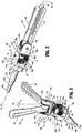
FIG. 2 is a perspective view of an end effector, according to an embodiment of the present disclosure, for use in the medical work station ofFIG. 1A , illustrating a jaw assembly thereof in a non-articulated and a closed condition; -
FIG. 3 is a perspective view of the end effector ofFIG. 2 illustrating the jaw assembly thereof in an articulated and an open condition; -
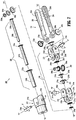
FIG. 4 is a perspective view, with parts separated, of the end effector ofFIGS. 2 and 3 ; -
FIG. 5 is a perspective view of an end effector, according to another embodiment of the present disclosure, for use in the medical work station ofFIG. 1A , illustrating a jaw assembly thereof in a non-articulated and a closed condition; -
FIG. 6 is a perspective view of the end effector ofFIG. 5 illustrating the jaw assembly thereof in an articulated and an open condition; -
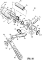
FIG. 7 is a perspective view, with parts separated, of the end effector ofFIGS. 5 and 6 ; -
FIG. 8 is a perspective view of an end effector, according to another embodiment of the present disclosure, for use in the medical work station ofFIG. 1A , illustrating a jaw assembly thereof in a non-articulated and a closed condition; -
FIG. 9 is a perspective view of the end effector ofFIG. 8 illustrating the jaw assembly thereof in an articulated and an open condition; and -
FIG. 10 is a perspective view, with parts separated, of the end effector ofFIGS. 8 and 9 . - Embodiments of the presently disclosed jaw assemblies and/or wrist assemblies are described in detail with reference to the drawings, in which like reference numerals designate identical or corresponding elements in each of the several views. As used herein the term "distal" refers to that portion of the jaw assembly and/or wrist assembly, that is farther from the user, while the term "proximal" refers to that portion of the jaw assembly and/or wrist assembly that is closer to the user.
- Referring initially to
FIGS. 1A and1B , a medical work station is shown generally aswork station 1 and generally includes a plurality ofrobot arms 2, 3; acontrol device 4; and an operating console 5 coupled withcontrol device 4. Operating console 5 includes adisplay device 6, which is set up in particular to display three-dimensional images; andmanual input devices 7, 8, by means of which a person (not shown), for example a surgeon, is able to telemanipulaterobot arms 2, 3 in a first operating mode, as known in principle to a person skilled in the art. - Each of the
robot arms 2, 3 includes a plurality of members, which are connected through joints, and an attachingdevice end effector 100, in accordance with any one of several embodiments disclosed herein, as will be described in greater detail below. -
Robot arms 2, 3 may be driven by electric drives (not shown) that are connected to controldevice 4. Control device 4 (e.g., a computer) is set up to activate the drives, in particular by means of a computer program, in such a way thatrobot arms 2, 3, their attachingdevices manual input devices 7, 8.Control device 4 may also be set up in such a way that it regulates the movement ofrobot arms 2, 3 and/or of the drives. -
Medical work station 1 is configured for use on a patient 13 lying on a patient table 12 to be treated in a minimally invasive manner by means ofend effector 100.Medical work station 1 may also include more than tworobot arms 2, 3, the additional robot arms likewise being connected to controldevice 4 and being telemanipulatable by means of operating console 5. A medical instrument or surgical tool (including an end effector 100) may also be attached to the additional robot arm. - Reference may be made to
U.S. Patent Publication No. 2012/0116416, filed on November 3, 2011 , entitled "Medical Workstation," the entire content of which is incorporated herein by reference, for a detailed discussion of the construction and operation ofmedical work station 1. -
Control device 4 may control a plurality of motors (Motor 1...n) with each motor configured to wind-up or let out a length of a cable "C" (FIG. 1B ) extending through each robot arm to endeffector 100 of the surgical tool, or to rotate a gear or a drive shaft (not shown). In use, as cables "C" are wound-up and let out, cables "C", gears or drive shafts may effect operation and/or movement of each end effector of the surgical tool. It is contemplated thatcontrol device 4 coordinates the activation of the various motors (Motor 1...n) to coordinate a winding-up or letting out a length of a respective cable "C" in order to coordinate an operation and/or movement of a respective end effector. AlthoughFIG. 1B shows a single cable "C" that is wound up or let out by a single motor, in some instances two or more cables or two ends of a single cable may be wound up or let out by a single motor. For example, in some instances, two cables or cable ends may be coupled in opposite directions to a single motor so that as the motor is activated in a first direction, one of the cables winds up while the other cable lets out. Other cable configurations may be used in different embodiments. - Turning now to
FIGS. 2-4 , an end effector for connection torobot arms 2, 3 and for manipulation bycontrol device 4, is generally designated as 100.End effector 100 includes awrist assembly 110, and ajaw assembly 130 pivotally connected towrist assembly 110.Wrist assembly 110 includes aproximal hub 112, in the form of a distally extending clevis, defining a first longitudinal axis "X1-X1."Proximal hub 112 defines a first pivot axis "Y-Y" that is oriented orthogonal to the first longitudinal axis "X1-X1." In an embodiment, first pivot axis "Y-Y" may extend through the first longitudinal axis "X1-X1."Proximal hub 112, being in the form of a clevis, includes a pair of spaced apart, opposed upright supports 112a, 112b through which first pivot axis "Y-Y" extends. -
Wrist assembly 110 further includes adistal hub assembly 116 pivotally connected toupright supports proximal hub 112.Distal hub assembly 116 includes a proximalU-shaped bracket 118 having a pair of spaced apart, opposed, proximally extending,upright supports Upright supports U-shaped bracket 118 are pivotally connected to respective upright supports 112a, 112b ofproximal hub 112, via apivot pin 114.Pivot pin 114 is disposed along first pivot axis "Y-Y". -
Distal hub assembly 116 further includes a distalU-shaped bracket 120 having a pair of spaced apart, opposed, distally extending,upright supports Upright supports U-shaped bracket 120 define a second pivot axis "Z-Z" therebetween.Backspan 120c of distalU-shaped bracket 120 is pivotally connected tobackspan 118c of proximalU-shaped bracket 118, about a second longitudinal axis "X2-X2." Second pivot axis "Z-Z" is oriented orthogonal to the first longitudinal axis "X1-X1." In an embodiment, when the first longitudinal axis "X1-X1" is parallel with the second longitudinal axis "X2-X2" (i.e.,end effector 100 is in an axially aligned orientation), second pivot axis "Z-Z" may extend through first longitudinal axis "X1-X1." - With continued reference to
FIGS. 2-4 , as mentioned above,end effector 100 includes ajaw assembly 130 that is pivotally supported on apivot pin 136 extending betweenupright supports U-shaped bracket 120 and along second pivot axis "B-B".Jaw assembly 130 includes a pair ofjaws upright supports U-shaped bracket 120. Specifically, eachjaw proximal end upright supports U-shaped bracket 120, viapivot pin 136; and a respectivedistal end distal end jaws - In accordance with the present disclosure and the present embodiment,
end effector 100 includes agear system 140 configured and adapted to transfer/transmit rotational forces generated by motors (Motor 1...n) ofcontrol device 4 into an articulation ofwrist assembly 110 along first pivot axis "Y-Y", a rotation ofjaw assembly 130 along second longitudinal axis "X2-X2", and an opening/closing ofjaw assembly 130. -
Gear system 140 includes afirst gear assembly 150 rotatably supported inproximal hub 112 ofwrist assembly 110.First gear assembly 150 includes a first orouter bevel gear 152a supported on a distal end of a first orouter drive tube 152b.Outer bevel gear 152a defines a first or relatively large diameter.Outer drive tube 152b defines a lumen therethrough having a longitudinal axis that is coaxial or parallel with the first longitudinal axis "X1-X1". A proximal end ofouter drive tube 152a may be acted upon, either directly or indirectly, by a respective motor (Motor 1...n) ofcontrol device 4 so as to be rotated about the longitudinal axis thereof. -
First gear assembly 150 also includes a second orintermediate bevel gear 154a supported on a distal end of a second orintermediate drive tube 154b.Intermediate bevel gear 154a defines a second or relatively intermediate diameter that is smaller than the diameter ofouter bevel gear 152a.Intermediate drive tube 154b defines a lumen therethrough having a longitudinal axis that is coaxial or parallel with the first longitudinal axis "X1-X1".Intermediate drive tube 154b is sized and dimensioned to be rotatably disposed within the lumen ofouter drive tube 152b. A proximal end ofintermediate drive tube 154a may be acted upon, either directly or indirectly, by a respective motor (Motor 1...n) ofcontrol device 4 so as to be rotated about the longitudinal axis thereof. -
First gear assembly 150 further also includes a third orinner bevel gear 156a supported on a distal end of a third orinner drive tube 156b.Inner bevel gear 156a defines a third or relatively small diameter that is smaller than the diameter ofintermediate bevel gear 154a.Inner drive tube 156b defines a lumen therethrough having a longitudinal axis that is coaxial or parallel with the first longitudinal axis "X1-X1".Inner drive tube 156b is sized and dimensioned to be rotatably disposed within the lumen ofintermediate drive tube 154b. A proximal end ofinner drive tube 156a may be acted upon, either directly or indirectly, by a respective motor (Motor 1...n) ofcontrol device 4 so as to be rotated about the longitudinal axis thereof. - As illustrated in
FIGS. 2-4 ,bevel gears first gear assembly 150 are arranged in a stacked and concentric configuration, whereinintermediate bevel gear 154a is stacked or disposed distal of and concentric withouter bevel gear 152a, andinner bevel gear 156a is stacked or disposed distal of and concentric withintermediate bevel gear 154a. -
Gear system 140 includes asecond gear assembly 160 rotatably supported in/on proximalU-shaped bracket 118 ofdistal hub assembly 116, and rotatably supported onpivot pin 114. Specifically,second gear assembly 160 includes a first orouter bevel gear 162a non-rotatably supported on or integrally formed in one of upright supports 118a, 118b of proximalU-shaped bracket 118.Outer bevel gear 162a ofsecond gear assembly 160 defines a first or relatively large diameter.Outer bevel gear 162a ofsecond gear assembly 160 is in meshing engagement withouter bevel gear 152a offirst gear assembly 150. -
Second gear assembly 160 also includes a second orintermediate bevel gear 164a rotatably supported onpivot pin 114.Intermediate bevel gear 164a ofsecond gear assembly 160 defines a second or intermediate diameter.Intermediate bevel gear 164a ofsecond gear assembly 160 is in meshing engagement withintermediate bevel gear 154a offirst gear assembly 150. -
Second gear assembly 160 further includes a third orinner bevel gear 166a rotatably supported onpivot pin 114.Inner bevel gear 166a ofsecond gear assembly 160 defines a third or small diameter.Inner bevel gear 166a ofsecond gear assembly 160 is in meshing engagement withinner bevel gear 156a offirst gear assembly 150. -
Bevel gears second gear assembly 160 are arranged in a stacked and concentric configuration, whereinintermediate bevel gear 164a is stacked or disposed atop and concentric withouter bevel gear 162a, andinner bevel gear 166a is stacked atop and concentric withintermediate bevel gear 164a. -
Gear system 140 includes athird gear assembly 170 rotatably supported in/on proximalU-shaped bracket 118 ofdistal hub assembly 116, specifically onbackspan 118c of proximalU-shaped bracket 118, between upright supports 118a, 118b.Third gear assembly 170 includes anintermediate bevel gear 174a keyed to or non-rotatably supported on astem 120d extending frombackspan 120c of distalU-shaped bracket 120 that extends throughbackspan 118c of proximalU-shaped bracket 118.Intermediate bevel gear 174a is axially disposed along second longitudinal axis "X2-X2".Intermediate bevel gear 174a ofthird gear assembly 170 defines an intermediate diameter.Intermediate bevel gear 174a ofthird gear assembly 170 is in meshing engagement withintermediate bevel gear 164a ofsecond gear assembly 160. -
Third gear assembly 170 further includes aninner bevel gear 176a keyed to or non-rotatably supported on astem 178b extending from ajaw bevel gear 178a rotatably disposed betweenupright supports U-shaped bracket 120.Stem 178b extends throughbackspan 120c of distalU-shaped bracket 120, throughbackspan 118c of proximalU-shaped bracket 118, and throughintermediate bevel gear 174a ofthird gear assembly 170.Inner bevel gear 176a is axially disposed along second longitudinal axis "X2-X2".Inner bevel gear 176a ofthird gear assembly 170 defines a small diameter.Inner bevel gear 176a ofthird gear assembly 170 is in meshing engagement withinner bevel gear 166a ofsecond gear assembly 160. -
Bevel gears third gear assembly 170 are arranged in a stacked and concentric configuration, whereininner bevel gear 176a is stacked or disposed proximal of and concentric withintermediate bevel gear 174a. - As illustrated in
FIGS. 2-4 ,proximal end 132a ofjaw 132 defines or non-rotatably supports abevel gear 132c, andproximal end 134a ofjaw 134 defines or non-rotatably supports abevel gear 134c. Eachbevel gear jaw bevel gear 178a. - In accordance with the present disclosure, a first gear train is defined which includes
outer bevel gear 152a offirst gear assembly 150, andouter bevel gear 162a ofsecond gear assembly 160. Also, a second gear train is defined which includesintermediate bevel gear 154a offirst gear assembly 150,intermediate bevel gear 164a ofsecond gear assembly 160, andintermediate bevel gear 174a ofthird gear assembly 170. Further, a third gear train is defined which includesinner bevel gear 156a offirst gear assembly 150,inner bevel gear 166a ofsecond gear assembly 160,inner bevel gear 176a ofthird gear assembly 170, jaw bevel gear 178, andbevel gears jaws - In operation, when the first gear train is actuated,
end effector 100 is pivoted or articulated about first pivot axis "Y-Y". Specifically, in operation, rotation ofouter tube 152b results in rotation ofouter bevel gear 152a offirst gear assembly 150, which results in rotation ofouter bevel gear 162a ofsecond gear assembly 160 to rotate proximalU-shaped bracket 118 ofdistal hub assembly 116 about first pivot axis "Y-Y" and thus pivotjaws - Also in operation, when the second gear train is actuated,
end effector 100 is rotated along second longitudinal axis "X2-X2". Specifically, in operation, rotation ofintermediate tube 154b results in rotation ofintermediate bevel gear 154a offirst gear assembly 150, which results in rotation ofintermediate bevel gear 164a ofsecond gear assembly 160, which results in rotation ofintermediate bevel gear 174a ofthird gear assembly 170 to rotate distalU-shaped bracket 120 ofdistal hub assembly 116 about second longitudinal axis "X2-X2" and thus rotatejaws - Additionally, in operation, when the third gear train is actuated,
end effector 100 actuated to open/close jaws inner tube 156b results in rotation ofinner bevel gear 156a offirst gear assembly 150, which results in rotation ofinner bevel gear 166a ofsecond gear assembly 160, which results in rotation ofinner bevel gear 176a ofthird gear assembly 170, which results in rotation ofjaw bevel gear 178a, and which results in opposed rotations ofbevel gears jaws jaws - Turning now to
FIGS. 5-7 , an end effector for connection torobot arms 2, 3 and for manipulation bycontrol device 4, in accordance with another embodiment of the present disclosure, is generally designated as 200. -
End effector 200 includes awrist assembly 210, and ajaw assembly 230 pivotally connected towrist assembly 210.Wrist assembly 210 includes aproximal hub 212, in the form of a distally extending clevis, defining a first longitudinal axis "X1-X1."Proximal hub 212 defines a first pivot axis "Y-Y" that is oriented orthogonal to the first longitudinal axis "X1-X1." In an embodiment, first pivot axis "Y-Y" may extend through the first longitudinal axis "X1-X1."Proximal hub 212, being in the form of a clevis, includes a pair of spaced apart, opposed upright supports 212a, 212b through which first pivot axis "Y-Y" extends. -
Wrist assembly 210 further includes adistal hub assembly 216 pivotally connected toupright supports proximal hub 212.Distal hub assembly 216 includes aproximal bracket 218 having a pair of spaced apart, opposed, proximally extending,upright supports backspan 218c. Proximal upright supports 218a, 218b ofproximal bracket 218 are pivotally connected to respective upright supports 212a, 212b ofproximal hub 212, via afirst pivot pin 214a.First pivot pin 214a defines a first pivot axis "Y-Y". -
Distal hub assembly 216 further includes adistal bracket 220 having a pair of spaced apart, opposed, proximally extending,upright supports backspan 220c. Proximal upright supports 220a, 220b ofdistal bracket 220 are pivotally connected to respective upright supports 218d, 218e ofproximal bracket 218, via asecond pivot pin 214b.Second pivot pin 214b defines a second pivot axis "W-W".Distal bracket 220 defines a second longitudinal axis "X2-X2." Second pivot axis "W-B" is oriented orthogonal to the first longitudinal axis "X1-X1." - With continued reference to
FIGS. 5-7 , as mentioned above,end effector 200 includes ajaw assembly 230 that is pivotally supported on athird pivot pin 214c extending between upright supports 220d, 220e ofdistal bracket 220 and along a third pivot axis "Z-Z".Jaw assembly 230 includes a pair ofjaws upright supports distal bracket 220. Specifically, eachjaw proximal end upright supports distal bracket 220, viathird pivot pin 214c; and a respectivedistal end distal end jaws - In accordance with the present disclosure and the present embodiment,
end effector 200 includes a gear system 240 (FIG. 6 ) configured and adapted to transfer/transmit rotational forces generated by motors (Motor 1...n) ofcontrol device 4 into an articulation ofwrist assembly 210 along first pivot axis "Y-Y", an articulation ofwrist assembly 210 along second pivot axis "W-W", and an opening/closing ofjaw assembly 230. -
Gear system 240 includes afirst gear assembly 250 rotatably supported inproximal hub 212 ofwrist assembly 210.First gear assembly 250 includes a first orouter bevel gear 252a supported on a distal end of a first orouter drive tube 252b.Outer bevel gear 252a defines a first or relatively large diameter.Outer drive tube 252b defines a lumen therethrough having a longitudinal axis that is coaxial or parallel with the first longitudinal axis "X1-X1". A proximal end ofouter drive tube 252a may be acted upon, either directly or indirectly, by a respective motor (Motor 1...n) ofcontrol device 4 so as to be rotated about the longitudinal axis thereof. -
First gear assembly 250 also includes a second orintermediate bevel gear 254a supported on a distal end of a second orintermediate drive tube 254b.Intermediate bevel gear 254a defines a second or relatively intermediate diameter that is smaller than the diameter ofouter bevel gear 252a.Intermediate drive tube 254b defines a lumen therethrough having a longitudinal axis that is coaxial or parallel with the first longitudinal axis "X1-X1".Intermediate drive tube 254b is sized and dimensioned to be rotatably disposed within the lumen ofouter drive tube 252b. A proximal end ofintermediate drive tube 254a may be acted upon, either directly or indirectly, by a respective motor (Motor 1...n) ofcontrol device 4 so as to be rotated about the longitudinal axis thereof. -
First gear assembly 250 further also includes a third orinner bevel gear 256a supported on a distal end of a third orinner drive tube 256b.Inner bevel gear 256a defines a third or relatively small diameter that is smaller than the diameter ofintermediate bevel gear 254a.Inner drive tube 256b defines a lumen therethrough having a longitudinal axis that is coaxial or parallel with the first longitudinal axis "X1-X1".Inner drive tube 256b is sized and dimensioned to be rotatably disposed within the lumen ofintermediate drive tube 254b. A proximal end ofinner drive tube 256a may be acted upon, either directly or indirectly, by a respective motor (Motor 1...n) ofcontrol device 4 so as to be rotated about the longitudinal axis thereof. - As illustrated in
FIGS. 5-7 ,bevel gears first gear assembly 250 are arranged in a stacked and concentric configuration, whereinintermediate bevel gear 254a is stacked or disposed distal of and concentric withouter bevel gear 252a, andinner bevel gear 256a is stacked or disposed distal of and concentric withintermediate bevel gear 254a. -
Gear system 240 includes asecond gear assembly 260 rotatably supported in/onproximal bracket 218 ofdistal hub assembly 216, and rotatably supported onfirst pivot pin 214a. Specifically,second gear assembly 260 includes a first orouter bevel gear 262a non-rotatably supported on or integrally formed in one of proximal upright supports 218a, 218b ofproximal bracket 218.Outer bevel gear 262a ofsecond gear assembly 260 defines a first or relatively large diameter.Outer bevel gear 262a ofsecond gear assembly 260 is in meshing engagement withouter bevel gear 252a offirst gear assembly 250. -
Second gear assembly 260 also includes a second orintermediate bevel gear 264a rotatably supported onfirst pivot pin 214a.Intermediate bevel gear 264a ofsecond gear assembly 260 defines a second or intermediate diameter.Intermediate bevel gear 264a ofsecond gear assembly 260 is in meshing engagement withintermediate bevel gear 254a offirst gear assembly 250. -
Second gear assembly 260 further includes a third orinner bevel gear 266a rotatably supported onfirst pivot pin 214a.Inner bevel gear 266a ofsecond gear assembly 260 defines a third or small diameter.Inner bevel gear 266a ofsecond gear assembly 260 is in meshing engagement withinner bevel gear 256a offirst gear assembly 250. -
Bevel gears second gear assembly 260 are arranged in a stacked and concentric configuration, whereinintermediate bevel gear 264a is stacked or disposed atop and concentric withouter bevel gear 262a, andinner bevel gear 266a is stacked atop and concentric withintermediate bevel gear 264a. -
Gear system 240 includes athird gear assembly 270 rotatably supported in/onproximal bracket 218 ofdistal hub assembly 216, specifically onbackspan 218c ofproximal bracket 218, between upright supports 218a, 218b and between upright supports 218d, 218e.Third gear assembly 270 includes a proximalintermediate bevel gear 274a keyed to or non-rotatably supported on astem 274c, that extends throughbackspan 218c, and which non-rotatably supports a distalintermediate bevel gear 274b. - Proximal and distal
intermediate bevel gears intermediate bevel gears third gear assembly 270 each define an intermediate diameter. Proximalintermediate bevel gear 274a ofthird gear assembly 270 is in meshing engagement withintermediate bevel gear 264a ofsecond gear assembly 260. -
Third gear assembly 270 further includes a proximalinner bevel gear 276a keyed to or non-rotatably supported on astem 276c, that extends throughstem 274c and throughbackspan 218c, and which non-rotatably supports a distalinner bevel gear 276b. Proximal and distalinner bevel gears inner bevel gears third gear assembly 270 each define a small diameter. Proximalinner bevel gear 276a ofthird gear assembly 270 is in meshing engagement withinner bevel gear 266a ofsecond gear assembly 260. -
Proximal bevel gears third gear assembly 270 are arranged in a stacked and concentric configuration, wherein proximalinner bevel gear 276a is stacked or disposed proximal of and concentric with proximalintermediate bevel gear 274a, and wherein distalinner bevel gear 276b is stacked or disposed distal of and concentric with distalintermediate bevel gear 274b. -
Gear system 240 additionally includes afourth gear assembly 280 rotatably supported in/onproximal bracket 218 ofdistal hub assembly 216, and rotatably supported onsecond pivot pin 214b. Specifically,fourth gear assembly 280 includes anintermediate bevel gear 284a rotatably supported onsecond pivot pin 214b, between distal upright supports 218d, 218e ofproximal bracket 218. Specifically,intermediate bevel gear 284a offourth gear assembly 280 is non-rotatably connected to one of distal upright supports 218d, 218e ofproximal bracket 218 or is integrally formed therewith.Intermediate bevel gear 284a offourth gear assembly 280 defines an intermediate diameter.Intermediate bevel gear 284a offourth gear assembly 280 is in meshing engagement with distalintermediate bevel gear 274b ofthird gear assembly 270. -
Fourth gear assembly 280 further includes aninner bevel gear 286a rotatably supported onsecond pivot pin 214b.Inner bevel gear 286a offourth gear assembly 280 defines a small diameter.Inner bevel gear 286a offourth gear assembly 280 is in meshing engagement withinner bevel gear 276b ofthird gear assembly 270. -
Bevel gears fourth gear assembly 280 are arranged in a stacked and concentric configuration, whereininner bevel gear 286a is stacked atop and concentric withintermediate bevel gear 284a. -
Gear system 240 includes afifth gear assembly 290 rotatably supported in/ondistal bracket 220 ofdistal hub assembly 216, specifically onbackspan 220c ofdistal bracket 220, between upright supports 220a, 220b and between upright supports 220d, 220e.Fifth gear assembly 290 includes a proximalinner bevel gear 296a keyed to or non-rotatably supported on astem 296c, that extends throughbackspan 220c, and which non-rotatably supports a distalinner bevel gear 296b that is disposed distal ofbackspan 220c ofdistal bracket 220. Proximal and distalinner bevel gears inner bevel gears fifth gear assembly 290 each define a small diameter. Proximalinner bevel gear 296a offifth gear assembly 290 is in meshing engagement withinner bevel gear 286a offourth gear assembly 280. - As illustrated in
FIGS. 5-7 ,proximal end 232a ofjaw 232 defines or non-rotatably supports abevel gear 232c, andproximal end 234a ofjaw 234 defines or non-rotatably supports abevel gear 234c. Eachbevel gear inner bevel gear 296b offifth gear assembly 290. - In accordance with the present disclosure, a first gear train is defined which includes
outer bevel gear 252a offirst gear assembly 250, andouter bevel gear 262a ofsecond gear assembly 260. Also, a second gear train is defined which includesintermediate bevel gear 254a offirst gear assembly 250,intermediate bevel gear 264a ofsecond gear assembly 260, intermediateproximal bevel gear 274a and intermediatedistal bevel gear 274b ofthird gear assembly 270, andintermediate bevel gear 284a offourth gear assembly 280. Further, a third gear train is defined which includesinner bevel gear 256a offirst gear assembly 250,inner bevel gear 266a ofsecond gear assembly 260, innerproximal bevel gear 276a and innerdistal bevel gear 276b ofthird gear assembly 270,inner bevel gear 286a offourth gear assembly 280, innerproximal bevel gear 296a and innerdistal bevel gear 296b offifth gear assembly 290, andbevel gears jaws - In operation, when the first gear train is actuated,
end effector 200 is pivoted or articulated about first pivot axis "Y-Y". Specifically, in operation, rotation ofouter tube 252b results in rotation ofouter bevel gear 252a offirst gear assembly 250, which results in rotation ofouter bevel gear 262a ofsecond gear assembly 260 to rotateproximal bracket 218 ofdistal hub assembly 216 about first pivot axis "Y-Y" and thus pivotjaws - Also in operation, when the second gear train is actuated,
end effector 200 is pivoted or articulated about second pivot axis "W-W". Specifically, in operation, rotation ofintermediate tube 254b results in rotation ofintermediate bevel gear 254a offirst gear assembly 250, which results in rotation ofintermediate bevel gear 264a ofsecond gear assembly 260, which results in rotation of intermediateproximal bevel gear 274a anddistal bevel gear 274b ofthird gear assembly 270, which results in rotation ofintermediate bevel gear 284a offourth gear assembly 280 to rotatedistal bracket 220 ofdistal hub assembly 216 about second pivot axis "W-W" and thus rotatejaws - Additionally, in operation, when the third gear train is actuated,
end effector 200 actuated to open/close jaws inner tube 256b results in rotation ofinner bevel gear 256a offirst gear assembly 250, which results in rotation ofinner bevel gear 266a ofsecond gear assembly 260, which results in rotation of innerproximal bevel gear 276a and innerdistal bevel gear 276b ofthird gear assembly 270, which results in rotation ofinner bevel gear 286a offourth gear assembly 280, which results in rotation of innerproximal bevel gear 296a anddistal bevel gear 296b offifth gear assembly 290, and which results in opposed rotations ofbevel gears jaws jaws - Turning now to
FIGS. 8-10 , an end effector for connection torobot arms 2, 3 and for manipulation bycontrol device 4, in accordance with another embodiment of the present disclosure, is generally designated as 300.End effector 300 includes awrist assembly 310, and ajaw assembly 330 pivotally connected towrist assembly 310.Wrist assembly 310 includes aproximal hub 312, in the form of a distally extending clevis, defining a first longitudinal axis "X1-X1."Proximal hub 312 defines a first pivot axis "Y-Y" that is oriented orthogonal to the first longitudinal axis "X1-X1." In an embodiment, first pivot axis "Y-Y" may extend through the first longitudinal axis "X1-X1."Proximal hub 312, being in the form of a clevis, includes a pair of spaced apart, opposed upright supports 312a, 312b through which first pivot axis "Y-Y" extends. -
Wrist assembly 310 further includes adistal hub assembly 316 pivotally connected toupright supports proximal hub 312.Distal hub assembly 316 includes a proximalU-shaped bracket 318 having a pair of spaced apart, opposed, proximally extending,upright supports Upright supports U-shaped bracket 318 are pivotally connected to respective upright supports 312a, 312b ofproximal hub 312, via a pivot pin (not shown) disposed along first pivot axis "Y-Y". -
Distal hub assembly 316 further includes a distalU-shaped bracket 320 having a pair of spaced apart, opposed, distally extending,upright supports Upright supports U-shaped bracket 320 define a second pivot axis "Z-Z" therebetween.Backspan 320c of distalU-shaped bracket 320 is pivotally connected tobackspan 318c of proximalU-shaped bracket 318, about a second longitudinal axis "X2-X2." Second pivot axis "Z-Z" is oriented orthogonal to the first longitudinal axis "X1-X1." - With continued reference to
FIGS. 8-10 , as mentioned above,end effector 300 includes ajaw assembly 330 that is pivotally supported on apivot pin 336 extending betweenupright supports U-shaped bracket 320 and along second pivot axis "B-B".Jaw assembly 330 includes a pair ofjaws upright supports U-shaped bracket 320. Specifically, eachjaw proximal end upright supports U-shaped bracket 320, viapivot pin 336; and a respectivedistal end distal end jaws - In accordance with the present disclosure and the present embodiment,
end effector 300 includes agear system 340 configured and adapted to transfer/transmit rotational forces generated by motors (Motor 1...n) ofcontrol device 4 into an articulation ofwrist assembly 310 along first pivot axis "Y-Y", a rotation ofjaw assembly 330 along second longitudinal axis "X2-X2", and an opening/closing ofjaw assembly 330. -
Gear system 340 includes abevel gear 352a supported on a distal end of anouter drive tube 352b.Outer drive tube 352b defines a lumen therethrough having a longitudinal axis that is coaxial or parallel with the first longitudinal axis "X1-X1". A proximal end ofouter drive tube 352a may be acted upon, either directly or indirectly, by a respective motor (Motor 1...n) ofcontrol device 4 so as to be rotated about the longitudinal axis thereof. -
Gear system 340 further includes afirst bevel gear 362a rotatably supported onupright support 318a of proximalU-shaped bracket 318, and asecond bevel gear 362b rotatably supported on one of upright supports 318b of proximalU-shaped bracket 318. First andsecond bevel gears bevel gear 352a. -
Gear system 340 also includes afirst bevel gear 372a keyed to or non-rotatably supported on astem 372c extending asecond bevel gear 372b, whereinstem 372c extends throughbackspan 320c of distalU-shaped bracket 320 and throughbackspan 318c of proximalU-shaped bracket 318. First andsecond bevel gears First bevel gear 372a is in meshing engagement with first andsecond bevel gears - As illustrated in
FIGS. 8-10 ,proximal end 332a ofjaw 332 defines or non-rotatably supports abevel gear 332c, andproximal end 334a ofjaw 334 defines or non-rotatably supports abevel gear 334c. Eachbevel gear second bevel gear 372b. - In accordance with the present disclosure, a gear train is defined which includes
bevel gear 352a, and first andsecond bevel gears second bevel gears bevel gears jaws end effector 300 is actuated,end effector 300 actuated to open/close jaws tube 352b results in rotation ofbevel gear 352a, which results in rotation of first andsecond bevel gears second bevel gears bevel gears jaws jaws - While bevel gears have been shown and described for incorporation into the end effectors herein described, it is contemplated and within the scope of the present disclosure that other types of gears may be used, individually or in combination with one another, such as, for example, spur gears, crown gears, worm gears, sprockets, and the like.
- With reference to
FIGS. 8-10 , a singlefirst cable 322 is at least partially wrapped around a cam plate orspool 326 and secured to at least one point thereof, or that the singlefirst cable 322 may be wrapped at least once aroundspool 326, in the manner of a capistan. Singlefirst cable 322 may include proximal ends that extend throughrobot arm 2 or 3 and operatively associated with a respective first motor and second motor (not shown) ofcontrol device 4. While a singlefirst cable 322 is shown and described, it is contemplated that a first pair of cables (not shown) including respective distal ends may be secured to opposed sides ofspool 326, or wrapped at least 180° aroundspool 326 and secured thereto, and including respective proximal ends extending throughrobot arm 2 or 3 and operatively associated with a respective first motor and second motor (not shown) ofcontrol device 4. - A single
second cable 324 is at least partially wrapped aroundspool 326 and secured to at least one point thereof, or that the singlesecond cable 324 may be wrapped at least once aroundspool 326, in the manner of a capistan. Singlesecond cable 324 may include proximal ends that extend throughrobot arm 2 or 3 and operatively associated with a respective first motor and second motor (not shown) ofcontrol device 4. While a singlesecond cable 324 is shown and described, it is contemplated that a first pair of cables (not shown) including respective distal ends may be secured to opposed sides ofspool 326, or wrapped at least 180° around spool 326and secured thereto, and including respective proximal ends extending throughrobot arm 2 or 3 and operatively associated with a respective first motor and second motor (not shown) ofcontrol device 4. -
Spool 326 is rotatably supported along first pivot axis "Y-Y" and betweenupright supports proximal hub 312. - In operation, as one proximal end of
first cable 322 orsecond cable 324 is drawn in by a corresponding motor, an other opposite end offirst cable 322 orsecond cable 324 is let out. In so doing,jaw assembly 330 may be pivoted about first pivot axis "Y-Y", in the direction of arrow "A". - In accordance with the present disclosure, end effectors that are compact in design, and yet may transmit relatively large forces or achieve a relatively large range of motion of pivoting and rotation, are contemplated and described. The gear trains disclosed herein enable transmission of relatively high loads, and may be accomplished with tight tolerances. Additionally, relatively high precision of control of movement of the end effectors is achieved.
- It will be understood that various modifications may be made to the embodiments disclosed herein. For example, while the cam pulleys disclosed herein have been shown and described as being connected to the proximal ends of the jaws, it is contemplated and within the scope of the appended claims, for the cam pulley to be operatively connected with the distal portion of the jaws. Therefore, the above description should not be construed as limiting, but merely as exemplifications of various embodiments. Those skilled in the art will envision other modifications within the scope of the claims appended thereto.
Claims (7)
- An end effector (100) connectable to a robot arm of a robotic surgical system and actuated by at least one motor of a control device of the robot surgical system, the end effector comprising:a wrist assembly (110) including:a proximal hub (112) defining a respective longitudinal axis; anda distal hub assembly (116) defining a respective longitudinal axis, the distal hub assembly includes:a proximal bracket (118) pivotally connected to the proximal hub (112), wherein the proximal bracket is U-shaped including a pair of spaced apart upright supports (118a, 118b) extending in a proximal direction that are interconnected by a backspan (118c); anda distal bracket (120) pivotally connected to the proximal bracket (118), the distal bracket being rotatable relative to the proximal bracket along the longitudinal axis of the distal hub assembly (116); anda jaw assembly (130) including a pair of jaws (132, 134) pivotally supported on the distal bracket (120), each jaw including:a proximal portion (132a, 134a) pivotally connected to the distal bracket (120); anda distal portion (132b, 134b) extending distally of the proximal portion thereof; andat least one gear train (150, 160, 170) supported in the wrist assembly, wherein the at least one gear train transmits forces from the at least one motor of the control device to at least one of the proximal bracket (118) of the wrist assembly, the distal bracket (120) of the wrist assembly and the jaw assembly (130); the at least one gear train enabling at least one of:a pivoting of the distal hub assembly (116) relative to the proximal hub (112);a rotation of the distal bracket (120) relative to the proximal bracket (118); andan opening or closing of the jaw assembly (130),wherein the at least one gear train includes a first gear train comprising:a first gear (152a) rotatably supported in the proximal hub (112), the first gear (152a) of the proximal hub being in operative communication with at least one motor of the control system; anda first gear (162a) non-rotatably supported on the proximal bracket (118) of the distal hub assembly (116), wherein the first gear (162a) of the proximal bracket defines a rotation axis that is co-axial with a pivot axis of the distal hub assembly (116) relative to the proximal hub (112), wherein the first gear (162a) of the proximal bracket is in meshing engagement with the first gear (152a) of the proximal hub;wherein the at least one gear train includes a second gear train comprising:a second gear (154a) rotatably supported in the proximal hub (112), the second gear (154a) of the proximal hub being in operative communication with at least one motor of the control system, the first gear (152a) and the second gear (154a) of the proximal hub being concentric;a second gear (164a) rotatably supported in the proximal bracket (118) of the distal hub assembly (116), wherein the first gear (162a) and the second gear (164a) of the proximal bracket are concentric; anda further second gear (174a) rotatably supported in the proximal bracket (118) of the distal hub assembly (116), wherein the further second gear (174a) defines a rotation axis that is co-axial with the longitudinal axis of the distal hub assembly (116), the further second gear (174a) being non-rotatably supported on a stem (120d) extending from the distal bracket (120) through the backspan (118c) of the proximal bracket (118),wherein the further second gear (174a) of the proximal bracket (118) is in meshing engagement with the second gear (164a) of the proximal bracket (118), and wherein the second gear (164a) of the proximal bracket (118) is in meshing engagement with the second gear (154a) of the proximal hub (112).
- The end effector according to claim 1, wherein the at least one gear train includes a third gear train comprising:a third gear (156a) rotatably supported in the proximal hub (112), the third gear (156a) of the proximal hub being in operative communication with at least one motor of the control system, the first (152a), second (154a) and third (156a) gears of the proximal hub (112) being concentric with one another;a third gear (166a) rotatably supported in the proximal bracket (118) of the distal hub assembly (116), wherein the first (162a), second (164a) and third (166a) gears of the proximal bracket (118) are concentric with one another; anda further third gear (176a) rotatably supported in the proximal bracket (118) of the distal hub assembly (116), wherein the further third gear (176a) is co-axial and concentric with the further second gear (174a) of the proximal bracket (118), the further third gear (176a) being non-rotatably supported on a stem (178b) extending from a gear (178a) rotatably supported in the distal bracket (120),wherein the further third gear (176a) of the proximal bracket (118) is in meshing engagement with the third gear (166a) of the proximal bracket (118), and wherein the third gear (116a) of the proximal bracket (118) is in meshing engagement with the third gear (156a) of the proximal hub (112).
- The end effector according to claim 2, wherein the at least one gear train includes a gear (178a) rotatably supported in the distal bracket (120) of the distal hub assembly (116), the gear (178a) of the distal bracket (120) being keyed to the further third gear (176a) of the proximal bracket (118), and wherein the proximal portion (132a, 134a) of each jaw is in meshing engagement with the gear (178a) of the distal bracket (120); and
wherein the first gear (152a) that is rotatably supported in the proximal hub (112) defines a first diameter; wherein the second gear (154a) that is rotatably supported in the proximal hub (112) defines a second diameter smaller than the first diameter; and wherein the third gear (156a) that is rotatably supported in the proximal hub (112) defines a third diameter that is smaller than the second diameter; and
wherein the first gear (162a) that is non-rotatably supported on the proximal bracket (118) defines a first diameter; wherein the second gear (164a) that is rotatably supported on the proximal bracket (118) defines a second diameter smaller than the first diameter;
and wherein the third gear (166a) that is rotatably supported on the proximal bracket (118) defines a third diameter that is smaller than the second diameter. - The end effector according to claim 2, wherein the further second gear (174a) that is rotatably supported on the proximal bracket (118) defines a diameter; and wherein the further third gear (176a) that is rotatably supported in the proximal bracket (118) defines a diameter that is smaller than the diameter of the further second gear.
- The end effector according to claim 3, wherein the first gear (162a) that is non-rotatably supported on the proximal bracket (118) and the second (164a) and third (166a) gears that are rotatably supported on the proximal bracket (118) are supported on one of the proximally extending upright supports (118a, 118b) of the proximal bracket (118); preferably wherein the further second gear (174a) and the further third gear (176a), that are rotatably supported on the proximal bracket (118), are supported on the backspan (118c) of the proximal bracket (118).
- The end effector according to claim 2, further comprising:a first drive tube (152b) extending through the proximal hub (112) and supporting the first gear (152a) on a distal end thereof, the first drive tube (152b) defining a lumen therethrough;a second drive tube (154b) extending through the proximal hub (112) and through the lumen of the first drive tube (152b), the second drive tube (154b) supporting the second gear (154a) on a distal end thereof, the second drive tube (154b) defining a lumen therethrough; anda third drive tube (156b) extending through the proximal hub (112) and through the lumen of the second drive tube (154b), the third drive tube (156b) supporting the third gear (156a) on a distal end thereof.
- The end effector according to claim 6, wherein the first gear (152a) that is rotatably supported in the proximal hub (112) defines a first diameter; wherein the second gear (154a) that is rotatably supported in the proximal hub (112) defines a second diameter smaller than the first diameter; and wherein the third gear (156a) that is rotatably supported in the proximal hub (112) defines a third diameter that is smaller than the second diameter.
Applications Claiming Priority (2)
| Application Number | Priority Date | Filing Date | Title |
|---|---|---|---|
| US201361914979P | 2013-12-12 | 2013-12-12 | |
| PCT/US2014/061863 WO2015088655A1 (en) | 2013-12-12 | 2014-10-23 | Gear train assemblies for robotic surgical systems |
Publications (3)
| Publication Number | Publication Date |
|---|---|
| EP3079609A1 EP3079609A1 (en) | 2016-10-19 |
| EP3079609A4 EP3079609A4 (en) | 2018-04-18 |
| EP3079609B1 true EP3079609B1 (en) | 2019-07-17 |
Family
ID=53371671
Family Applications (1)
| Application Number | Title | Priority Date | Filing Date |
|---|---|---|---|
| EP14870110.5A Active EP3079609B1 (en) | 2013-12-12 | 2014-10-23 | Gear train assemblies for robotic surgical systems |
Country Status (4)
| Country | Link |
|---|---|
| US (1) | US10220522B2 (en) |
| EP (1) | EP3079609B1 (en) |
| CN (2) | CN105813580B (en) |
| WO (1) | WO2015088655A1 (en) |
Families Citing this family (538)
| Publication number | Priority date | Publication date | Assignee | Title |
|---|---|---|---|---|
| US9060770B2 (en) | 2003-05-20 | 2015-06-23 | Ethicon Endo-Surgery, Inc. | Robotically-driven surgical instrument with E-beam driver |
| US20070084897A1 (en) | 2003-05-20 | 2007-04-19 | Shelton Frederick E Iv | Articulating surgical stapling instrument incorporating a two-piece e-beam firing mechanism |
| US8215531B2 (en) | 2004-07-28 | 2012-07-10 | Ethicon Endo-Surgery, Inc. | Surgical stapling instrument having a medical substance dispenser |
| US11890012B2 (en) | 2004-07-28 | 2024-02-06 | Cilag Gmbh International | Staple cartridge comprising cartridge body and attached support |
| US10159482B2 (en) | 2005-08-31 | 2018-12-25 | Ethicon Llc | Fastener cartridge assembly comprising a fixed anvil and different staple heights |
| US9237891B2 (en) | 2005-08-31 | 2016-01-19 | Ethicon Endo-Surgery, Inc. | Robotically-controlled surgical stapling devices that produce formed staples having different lengths |
| US7934630B2 (en) | 2005-08-31 | 2011-05-03 | Ethicon Endo-Surgery, Inc. | Staple cartridges for forming staples having differing formed staple heights |
| US11484312B2 (en) | 2005-08-31 | 2022-11-01 | Cilag Gmbh International | Staple cartridge comprising a staple driver arrangement |
| US7669746B2 (en) | 2005-08-31 | 2010-03-02 | Ethicon Endo-Surgery, Inc. | Staple cartridges for forming staples having differing formed staple heights |
| US11246590B2 (en) | 2005-08-31 | 2022-02-15 | Cilag Gmbh International | Staple cartridge including staple drivers having different unfired heights |
| US20070106317A1 (en) | 2005-11-09 | 2007-05-10 | Shelton Frederick E Iv | Hydraulically and electrically actuated articulation joints for surgical instruments |
| US20120292367A1 (en) | 2006-01-31 | 2012-11-22 | Ethicon Endo-Surgery, Inc. | Robotically-controlled end effector |
| US7845537B2 (en) | 2006-01-31 | 2010-12-07 | Ethicon Endo-Surgery, Inc. | Surgical instrument having recording capabilities |
| US8820603B2 (en) | 2006-01-31 | 2014-09-02 | Ethicon Endo-Surgery, Inc. | Accessing data stored in a memory of a surgical instrument |
| US11224427B2 (en) | 2006-01-31 | 2022-01-18 | Cilag Gmbh International | Surgical stapling system including a console and retraction assembly |
| US11278279B2 (en) | 2006-01-31 | 2022-03-22 | Cilag Gmbh International | Surgical instrument assembly |
| US7753904B2 (en) | 2006-01-31 | 2010-07-13 | Ethicon Endo-Surgery, Inc. | Endoscopic surgical instrument with a handle that can articulate with respect to the shaft |
| US11793518B2 (en) | 2006-01-31 | 2023-10-24 | Cilag Gmbh International | Powered surgical instruments with firing system lockout arrangements |
| US20110290856A1 (en) | 2006-01-31 | 2011-12-01 | Ethicon Endo-Surgery, Inc. | Robotically-controlled surgical instrument with force-feedback capabilities |
| US8186555B2 (en) | 2006-01-31 | 2012-05-29 | Ethicon Endo-Surgery, Inc. | Motor-driven surgical cutting and fastening instrument with mechanical closure system |
| US8708213B2 (en) | 2006-01-31 | 2014-04-29 | Ethicon Endo-Surgery, Inc. | Surgical instrument having a feedback system |
| US20110024477A1 (en) | 2009-02-06 | 2011-02-03 | Hall Steven G | Driven Surgical Stapler Improvements |
| US8992422B2 (en) | 2006-03-23 | 2015-03-31 | Ethicon Endo-Surgery, Inc. | Robotically-controlled endoscopic accessory channel |
| US8322455B2 (en) | 2006-06-27 | 2012-12-04 | Ethicon Endo-Surgery, Inc. | Manually driven surgical cutting and fastening instrument |
| US10568652B2 (en) | 2006-09-29 | 2020-02-25 | Ethicon Llc | Surgical staples having attached drivers of different heights and stapling instruments for deploying the same |
| US8652120B2 (en) | 2007-01-10 | 2014-02-18 | Ethicon Endo-Surgery, Inc. | Surgical instrument with wireless communication between control unit and sensor transponders |
| US11291441B2 (en) | 2007-01-10 | 2022-04-05 | Cilag Gmbh International | Surgical instrument with wireless communication between control unit and remote sensor |
| US8684253B2 (en) | 2007-01-10 | 2014-04-01 | Ethicon Endo-Surgery, Inc. | Surgical instrument with wireless communication between a control unit of a robotic system and remote sensor |
| US11039836B2 (en) | 2007-01-11 | 2021-06-22 | Cilag Gmbh International | Staple cartridge for use with a surgical stapling instrument |
| US8540128B2 (en) | 2007-01-11 | 2013-09-24 | Ethicon Endo-Surgery, Inc. | Surgical stapling device with a curved end effector |
| US8727197B2 (en) | 2007-03-15 | 2014-05-20 | Ethicon Endo-Surgery, Inc. | Staple cartridge cavity configuration with cooperative surgical staple |
| US8931682B2 (en) | 2007-06-04 | 2015-01-13 | Ethicon Endo-Surgery, Inc. | Robotically-controlled shaft based rotary drive systems for surgical instruments |
| US11857181B2 (en) | 2007-06-04 | 2024-01-02 | Cilag Gmbh International | Robotically-controlled shaft based rotary drive systems for surgical instruments |
| US7753245B2 (en) | 2007-06-22 | 2010-07-13 | Ethicon Endo-Surgery, Inc. | Surgical stapling instruments |
| US11849941B2 (en) | 2007-06-29 | 2023-12-26 | Cilag Gmbh International | Staple cartridge having staple cavities extending at a transverse angle relative to a longitudinal cartridge axis |
| US8573465B2 (en) | 2008-02-14 | 2013-11-05 | Ethicon Endo-Surgery, Inc. | Robotically-controlled surgical end effector system with rotary actuated closure systems |
| US7866527B2 (en) | 2008-02-14 | 2011-01-11 | Ethicon Endo-Surgery, Inc. | Surgical stapling apparatus with interlockable firing system |
| US8636736B2 (en) | 2008-02-14 | 2014-01-28 | Ethicon Endo-Surgery, Inc. | Motorized surgical cutting and fastening instrument |
| US9179912B2 (en) | 2008-02-14 | 2015-11-10 | Ethicon Endo-Surgery, Inc. | Robotically-controlled motorized surgical cutting and fastening instrument |
| US7819298B2 (en) | 2008-02-14 | 2010-10-26 | Ethicon Endo-Surgery, Inc. | Surgical stapling apparatus with control features operable with one hand |
| US8758391B2 (en) | 2008-02-14 | 2014-06-24 | Ethicon Endo-Surgery, Inc. | Interchangeable tools for surgical instruments |
| BRPI0901282A2 (en) | 2008-02-14 | 2009-11-17 | Ethicon Endo Surgery Inc | surgical cutting and fixation instrument with rf electrodes |
| US9770245B2 (en) | 2008-02-15 | 2017-09-26 | Ethicon Llc | Layer arrangements for surgical staple cartridges |
| US9386983B2 (en) | 2008-09-23 | 2016-07-12 | Ethicon Endo-Surgery, Llc | Robotically-controlled motorized surgical instrument |
| US9005230B2 (en) | 2008-09-23 | 2015-04-14 | Ethicon Endo-Surgery, Inc. | Motorized surgical instrument |
| US11648005B2 (en) | 2008-09-23 | 2023-05-16 | Cilag Gmbh International | Robotically-controlled motorized surgical instrument with an end effector |
| US8210411B2 (en) | 2008-09-23 | 2012-07-03 | Ethicon Endo-Surgery, Inc. | Motor-driven surgical cutting instrument |
| US8608045B2 (en) | 2008-10-10 | 2013-12-17 | Ethicon Endo-Sugery, Inc. | Powered surgical cutting and stapling apparatus with manually retractable firing system |
| US8517239B2 (en) | 2009-02-05 | 2013-08-27 | Ethicon Endo-Surgery, Inc. | Surgical stapling instrument comprising a magnetic element driver |
| CN102341048A (en) | 2009-02-06 | 2012-02-01 | 伊西康内外科公司 | Driven surgical stapler improvements |
| US8851354B2 (en) | 2009-12-24 | 2014-10-07 | Ethicon Endo-Surgery, Inc. | Surgical cutting instrument that analyzes tissue thickness |
| US8220688B2 (en) | 2009-12-24 | 2012-07-17 | Ethicon Endo-Surgery, Inc. | Motor-driven surgical cutting instrument with electric actuator directional control assembly |
| US8783543B2 (en) | 2010-07-30 | 2014-07-22 | Ethicon Endo-Surgery, Inc. | Tissue acquisition arrangements and methods for surgical stapling devices |
| US9016542B2 (en) | 2010-09-30 | 2015-04-28 | Ethicon Endo-Surgery, Inc. | Staple cartridge comprising compressible distortion resistant components |
| US11849952B2 (en) | 2010-09-30 | 2023-12-26 | Cilag Gmbh International | Staple cartridge comprising staples positioned within a compressible portion thereof |
| US10945731B2 (en) | 2010-09-30 | 2021-03-16 | Ethicon Llc | Tissue thickness compensator comprising controlled release and expansion |
| US11298125B2 (en) | 2010-09-30 | 2022-04-12 | Cilag Gmbh International | Tissue stapler having a thickness compensator |
| US9211120B2 (en) | 2011-04-29 | 2015-12-15 | Ethicon Endo-Surgery, Inc. | Tissue thickness compensator comprising a plurality of medicaments |
| US11812965B2 (en) | 2010-09-30 | 2023-11-14 | Cilag Gmbh International | Layer of material for a surgical end effector |
| US9629814B2 (en) | 2010-09-30 | 2017-04-25 | Ethicon Endo-Surgery, Llc | Tissue thickness compensator configured to redistribute compressive forces |
| US9386988B2 (en) | 2010-09-30 | 2016-07-12 | Ethicon End-Surgery, LLC | Retainer assembly including a tissue thickness compensator |
| US9282962B2 (en) | 2010-09-30 | 2016-03-15 | Ethicon Endo-Surgery, Llc | Adhesive film laminate |
| US8695866B2 (en) | 2010-10-01 | 2014-04-15 | Ethicon Endo-Surgery, Inc. | Surgical instrument having a power control circuit |
| WO2012049623A1 (en) | 2010-10-11 | 2012-04-19 | Ecole Polytechnique Federale De Lausanne (Epfl) | Mechanical manipulator for surgical instruments |
| CA2834649C (en) | 2011-04-29 | 2021-02-16 | Ethicon Endo-Surgery, Inc. | Staple cartridge comprising staples positioned within a compressible portion thereof |
| US11207064B2 (en) | 2011-05-27 | 2021-12-28 | Cilag Gmbh International | Automated end effector component reloading system for use with a robotic system |
| US9072535B2 (en) | 2011-05-27 | 2015-07-07 | Ethicon Endo-Surgery, Inc. | Surgical stapling instruments with rotatable staple deployment arrangements |
| CA2838637C (en) | 2011-06-10 | 2020-11-17 | Board Of Regents Of The University Of Nebraska | Methods, systems, and devices relating to surgical end effectors |
| CA3082073C (en) | 2011-07-11 | 2023-07-25 | Board Of Regents Of The University Of Nebraska | Robotic surgical devices, systems, and related methods |
| US9696700B2 (en) | 2011-07-27 | 2017-07-04 | Ecole Polytechnique Federale De Lausanne | Mechanical teleoperated device for remote manipulation |
| WO2013063674A1 (en) | 2011-11-04 | 2013-05-10 | Titan Medical Inc. | Apparatus and method for controlling an end-effector assembly |
| CA2860754C (en) | 2012-01-10 | 2020-12-29 | Shane Farritor | Methods, systems, and devices for surgical access and insertion |
| US9044230B2 (en) | 2012-02-13 | 2015-06-02 | Ethicon Endo-Surgery, Inc. | Surgical cutting and fastening instrument with apparatus for determining cartridge and firing motion status |
| CN104379068B (en) | 2012-03-28 | 2017-09-22 | 伊西康内外科公司 | Holding device assembly including tissue thickness compensation part |
| BR112014024098B1 (en) | 2012-03-28 | 2021-05-25 | Ethicon Endo-Surgery, Inc. | staple cartridge |
| BR112014024102B1 (en) | 2012-03-28 | 2022-03-03 | Ethicon Endo-Surgery, Inc | CLAMP CARTRIDGE ASSEMBLY FOR A SURGICAL INSTRUMENT AND END ACTUATOR ASSEMBLY FOR A SURGICAL INSTRUMENT |
| US9498292B2 (en) | 2012-05-01 | 2016-11-22 | Board Of Regents Of The University Of Nebraska | Single site robotic device and related systems and methods |
| US11871901B2 (en) | 2012-05-20 | 2024-01-16 | Cilag Gmbh International | Method for situational awareness for surgical network or surgical network connected device capable of adjusting function based on a sensed situation or usage |
| US9101358B2 (en) | 2012-06-15 | 2015-08-11 | Ethicon Endo-Surgery, Inc. | Articulatable surgical instrument comprising a firing drive |
| US9364220B2 (en) | 2012-06-19 | 2016-06-14 | Covidien Lp | Apparatus for endoscopic procedures |
| US9282974B2 (en) | 2012-06-28 | 2016-03-15 | Ethicon Endo-Surgery, Llc | Empty clip cartridge lockout |
| BR112014032776B1 (en) | 2012-06-28 | 2021-09-08 | Ethicon Endo-Surgery, Inc | SURGICAL INSTRUMENT SYSTEM AND SURGICAL KIT FOR USE WITH A SURGICAL INSTRUMENT SYSTEM |
| US9289256B2 (en) | 2012-06-28 | 2016-03-22 | Ethicon Endo-Surgery, Llc | Surgical end effectors having angled tissue-contacting surfaces |
| US9226751B2 (en) | 2012-06-28 | 2016-01-05 | Ethicon Endo-Surgery, Inc. | Surgical instrument system including replaceable end effectors |
| JP6290201B2 (en) | 2012-06-28 | 2018-03-07 | エシコン・エンド−サージェリィ・インコーポレイテッドEthicon Endo−Surgery,Inc. | Lockout for empty clip cartridge |
| US11278284B2 (en) | 2012-06-28 | 2022-03-22 | Cilag Gmbh International | Rotary drive arrangements for surgical instruments |
| US9204879B2 (en) | 2012-06-28 | 2015-12-08 | Ethicon Endo-Surgery, Inc. | Flexible drive member |
| US20140001231A1 (en) | 2012-06-28 | 2014-01-02 | Ethicon Endo-Surgery, Inc. | Firing system lockout arrangements for surgical instruments |
| US9402604B2 (en) | 2012-07-20 | 2016-08-02 | Covidien Lp | Apparatus for endoscopic procedures |
| JP2015526171A (en) | 2012-08-08 | 2015-09-10 | ボード オブ リージェンツ オブ ザ ユニバーシティ オブ ネブラスカ | Robotic surgical device, system and related methods |
| US9770305B2 (en) | 2012-08-08 | 2017-09-26 | Board Of Regents Of The University Of Nebraska | Robotic surgical devices, systems, and related methods |
| JP6345707B2 (en) | 2013-03-01 | 2018-06-20 | エシコン・エンド−サージェリィ・インコーポレイテッドEthicon Endo−Surgery,Inc. | Surgical instrument with soft stop |
| JP6382235B2 (en) | 2013-03-01 | 2018-08-29 | エシコン・エンド−サージェリィ・インコーポレイテッドEthicon Endo−Surgery,Inc. | Articulatable surgical instrument with a conductive path for signal communication |
| CA2905948C (en) | 2013-03-14 | 2022-01-11 | Board Of Regents Of The University Of Nebraska | Methods, systems, and devices relating to robotic surgical devices, end effectors, and controllers |
| US9332987B2 (en) | 2013-03-14 | 2016-05-10 | Ethicon Endo-Surgery, Llc | Control arrangements for a drive member of a surgical instrument |
| US9629629B2 (en) | 2013-03-14 | 2017-04-25 | Ethicon Endo-Surgey, LLC | Control systems for surgical instruments |
| US10667883B2 (en) | 2013-03-15 | 2020-06-02 | Virtual Incision Corporation | Robotic surgical devices, systems, and related methods |
| US9844368B2 (en) | 2013-04-16 | 2017-12-19 | Ethicon Llc | Surgical system comprising first and second drive systems |
| BR112015026109B1 (en) | 2013-04-16 | 2022-02-22 | Ethicon Endo-Surgery, Inc | surgical instrument |
| EP3021779A4 (en) | 2013-07-17 | 2017-08-23 | Board of Regents of the University of Nebraska | Robotic surgical devices, systems and related methods |
| JP6416260B2 (en) | 2013-08-23 | 2018-10-31 | エシコン エルエルシー | Firing member retractor for a powered surgical instrument |
| US20150053746A1 (en) | 2013-08-23 | 2015-02-26 | Ethicon Endo-Surgery, Inc. | Torque optimization for surgical instruments |
| JP6220085B2 (en) | 2014-02-03 | 2017-10-25 | ディスタルモーション エスエーDistalmotion Sa | Mechanical remote control device with replaceable distal device |
| US9962161B2 (en) | 2014-02-12 | 2018-05-08 | Ethicon Llc | Deliverable surgical instrument |
| BR112016021943B1 (en) | 2014-03-26 | 2022-06-14 | Ethicon Endo-Surgery, Llc | SURGICAL INSTRUMENT FOR USE BY AN OPERATOR IN A SURGICAL PROCEDURE |
| US9733663B2 (en) | 2014-03-26 | 2017-08-15 | Ethicon Llc | Power management through segmented circuit and variable voltage protection |
| US10004497B2 (en) | 2014-03-26 | 2018-06-26 | Ethicon Llc | Interface systems for use with surgical instruments |
| JP6636452B2 (en) | 2014-04-16 | 2020-01-29 | エシコン エルエルシーEthicon LLC | Fastener cartridge including extension having different configurations |
| BR112016023825B1 (en) | 2014-04-16 | 2022-08-02 | Ethicon Endo-Surgery, Llc | STAPLE CARTRIDGE FOR USE WITH A SURGICAL STAPLER AND STAPLE CARTRIDGE FOR USE WITH A SURGICAL INSTRUMENT |
| US20150297223A1 (en) | 2014-04-16 | 2015-10-22 | Ethicon Endo-Surgery, Inc. | Fastener cartridges including extensions having different configurations |
| JP6532889B2 (en) | 2014-04-16 | 2019-06-19 | エシコン エルエルシーEthicon LLC | Fastener cartridge assembly and staple holder cover arrangement |
| US10561422B2 (en) | 2014-04-16 | 2020-02-18 | Ethicon Llc | Fastener cartridge comprising deployable tissue engaging members |
| US10327764B2 (en) | 2014-09-26 | 2019-06-25 | Ethicon Llc | Method for creating a flexible staple line |
| WO2016030767A1 (en) | 2014-08-27 | 2016-03-03 | Distalmotion Sa | Surgical system for microsurgical techniques |
| BR112017004361B1 (en) | 2014-09-05 | 2023-04-11 | Ethicon Llc | ELECTRONIC SYSTEM FOR A SURGICAL INSTRUMENT |
| US11311294B2 (en) | 2014-09-05 | 2022-04-26 | Cilag Gmbh International | Powered medical device including measurement of closure state of jaws |
| US10111679B2 (en) | 2014-09-05 | 2018-10-30 | Ethicon Llc | Circuitry and sensors for powered medical device |
| US10105142B2 (en) | 2014-09-18 | 2018-10-23 | Ethicon Llc | Surgical stapler with plurality of cutting elements |
| US11523821B2 (en) | 2014-09-26 | 2022-12-13 | Cilag Gmbh International | Method for creating a flexible staple line |
| JP6648119B2 (en) | 2014-09-26 | 2020-02-14 | エシコン エルエルシーEthicon LLC | Surgical stapling buttress and accessory materials |
| US10076325B2 (en) | 2014-10-13 | 2018-09-18 | Ethicon Llc | Surgical stapling apparatus comprising a tissue stop |
| US9924944B2 (en) | 2014-10-16 | 2018-03-27 | Ethicon Llc | Staple cartridge comprising an adjunct material |
| US10517594B2 (en) | 2014-10-29 | 2019-12-31 | Ethicon Llc | Cartridge assemblies for surgical staplers |
| US11141153B2 (en) | 2014-10-29 | 2021-10-12 | Cilag Gmbh International | Staple cartridges comprising driver arrangements |
| US11504192B2 (en) | 2014-10-30 | 2022-11-22 | Cilag Gmbh International | Method of hub communication with surgical instrument systems |
| US9844376B2 (en) | 2014-11-06 | 2017-12-19 | Ethicon Llc | Staple cartridge comprising a releasable adjunct material |
| CA2967593C (en) | 2014-11-11 | 2024-02-27 | Board Of Regents Of The University Of Nebraska | Robotic device with compact joint design and related systems and methods |
| US10736636B2 (en) | 2014-12-10 | 2020-08-11 | Ethicon Llc | Articulatable surgical instrument system |
| US9844374B2 (en) | 2014-12-18 | 2017-12-19 | Ethicon Llc | Surgical instrument systems comprising an articulatable end effector and means for adjusting the firing stroke of a firing member |
| US10004501B2 (en) | 2014-12-18 | 2018-06-26 | Ethicon Llc | Surgical instruments with improved closure arrangements |
| US9844375B2 (en) | 2014-12-18 | 2017-12-19 | Ethicon Llc | Drive arrangements for articulatable surgical instruments |
| MX2017008108A (en) | 2014-12-18 | 2018-03-06 | Ethicon Llc | Surgical instrument with an anvil that is selectively movable about a discrete non-movable axis relative to a staple cartridge. |
| US9987000B2 (en) | 2014-12-18 | 2018-06-05 | Ethicon Llc | Surgical instrument assembly comprising a flexible articulation system |
| US10085748B2 (en) | 2014-12-18 | 2018-10-02 | Ethicon Llc | Locking arrangements for detachable shaft assemblies with articulatable surgical end effectors |
| EP3653145B1 (en) | 2014-12-19 | 2024-01-24 | DistalMotion SA | Reusable surgical instrument for minimally invasive procedures |
| EP4289385A3 (en) | 2014-12-19 | 2024-03-27 | DistalMotion SA | Surgical instrument with articulated end-effector |
| US11039820B2 (en) | 2014-12-19 | 2021-06-22 | Distalmotion Sa | Sterile interface for articulated surgical instruments |
| US10548680B2 (en) | 2014-12-19 | 2020-02-04 | Distalmotion Sa | Articulated handle for mechanical telemanipulator |
| WO2016097871A1 (en) | 2014-12-19 | 2016-06-23 | Distalmotion Sa | Docking system for mechanical telemanipulator |
| US11154301B2 (en) | 2015-02-27 | 2021-10-26 | Cilag Gmbh International | Modular stapling assembly |
| US10617412B2 (en) | 2015-03-06 | 2020-04-14 | Ethicon Llc | System for detecting the mis-insertion of a staple cartridge into a surgical stapler |
| US10245033B2 (en) | 2015-03-06 | 2019-04-02 | Ethicon Llc | Surgical instrument comprising a lockable battery housing |
| US10687806B2 (en) | 2015-03-06 | 2020-06-23 | Ethicon Llc | Adaptive tissue compression techniques to adjust closure rates for multiple tissue types |
| US10441279B2 (en) | 2015-03-06 | 2019-10-15 | Ethicon Llc | Multiple level thresholds to modify operation of powered surgical instruments |
| US9901342B2 (en) | 2015-03-06 | 2018-02-27 | Ethicon Endo-Surgery, Llc | Signal and power communication system positioned on a rotatable shaft |
| JP2020121162A (en) | 2015-03-06 | 2020-08-13 | エシコン エルエルシーEthicon LLC | Time dependent evaluation of sensor data to determine stability element, creep element and viscoelastic element of measurement |
| US9924961B2 (en) | 2015-03-06 | 2018-03-27 | Ethicon Endo-Surgery, Llc | Interactive feedback system for powered surgical instruments |
| US10548504B2 (en) | 2015-03-06 | 2020-02-04 | Ethicon Llc | Overlaid multi sensor radio frequency (RF) electrode system to measure tissue compression |
| US9993248B2 (en) | 2015-03-06 | 2018-06-12 | Ethicon Endo-Surgery, Llc | Smart sensors with local signal processing |
| US10925685B2 (en) * | 2015-03-25 | 2021-02-23 | Sony Olympus Medical Solutions Inc. | Medical observation device, surgical observation device, and medical observation system |
| US10213201B2 (en) | 2015-03-31 | 2019-02-26 | Ethicon Llc | Stapling end effector configured to compensate for an uneven gap between a first jaw and a second jaw |
| US10363055B2 (en) | 2015-04-09 | 2019-07-30 | Distalmotion Sa | Articulated hand-held instrument |
| US10568709B2 (en) | 2015-04-09 | 2020-02-25 | Distalmotion Sa | Mechanical teleoperated device for remote manipulation |
| GB2540756B (en) * | 2015-07-22 | 2021-03-31 | Cmr Surgical Ltd | Gear packaging for robot arms |
| GB2541369B (en) * | 2015-07-22 | 2021-03-31 | Cmr Surgical Ltd | Drive mechanisms for robot arms |
| JP6997075B2 (en) | 2015-07-22 | 2022-01-17 | シーエムアール サージカル リミテッド | Robot arm |
| GB201512964D0 (en) * | 2015-07-22 | 2015-09-02 | Cambridge Medical Robotics Ltd | Communication paths for robot arms |
| WO2017024081A1 (en) | 2015-08-03 | 2017-02-09 | Board Of Regents Of The University Of Nebraska | Robotic surgical devices systems and related methods |
| DE102015215469A1 (en) * | 2015-08-13 | 2017-02-16 | Richard Wolf Gmbh | Instrument, in particular medical endoscopic instrument |
| US11058425B2 (en) | 2015-08-17 | 2021-07-13 | Ethicon Llc | Implantable layers for a surgical instrument |
| US10786272B2 (en) | 2015-08-28 | 2020-09-29 | Distalmotion Sa | Surgical instrument with increased actuation force |
| US10238386B2 (en) | 2015-09-23 | 2019-03-26 | Ethicon Llc | Surgical stapler having motor control based on an electrical parameter related to a motor current |
| US10105139B2 (en) | 2015-09-23 | 2018-10-23 | Ethicon Llc | Surgical stapler having downstream current-based motor control |
| US10299878B2 (en) | 2015-09-25 | 2019-05-28 | Ethicon Llc | Implantable adjunct systems for determining adjunct skew |
| US10980539B2 (en) | 2015-09-30 | 2021-04-20 | Ethicon Llc | Implantable adjunct comprising bonded layers |
| US11890015B2 (en) | 2015-09-30 | 2024-02-06 | Cilag Gmbh International | Compressible adjunct with crossing spacer fibers |
| US10285699B2 (en) | 2015-09-30 | 2019-05-14 | Ethicon Llc | Compressible adjunct |
| US10327777B2 (en) | 2015-09-30 | 2019-06-25 | Ethicon Llc | Implantable layer comprising plastically deformed fibers |
| EP3155991B1 (en) * | 2015-10-14 | 2020-01-15 | Karl Storz SE & Co. KG | Distal head assembly for a bipolar instrument, bipolar instrument and method of assembling a distal head assembly |
| ITUB20154977A1 (en) | 2015-10-16 | 2017-04-16 | Medical Microinstruments S R L | Medical instrument and method of manufacture of said medical instrument |
| US10265068B2 (en) | 2015-12-30 | 2019-04-23 | Ethicon Llc | Surgical instruments with separable motors and motor control circuits |
| US10292704B2 (en) | 2015-12-30 | 2019-05-21 | Ethicon Llc | Mechanisms for compensating for battery pack failure in powered surgical instruments |
| US10368865B2 (en) | 2015-12-30 | 2019-08-06 | Ethicon Llc | Mechanisms for compensating for drivetrain failure in powered surgical instruments |
| US10864003B2 (en) * | 2016-02-05 | 2020-12-15 | Covidien Lp | Articulation assemblies for use with endoscopic surgical instruments |
| US11213293B2 (en) | 2016-02-09 | 2022-01-04 | Cilag Gmbh International | Articulatable surgical instruments with single articulation link arrangements |
| US20170224332A1 (en) | 2016-02-09 | 2017-08-10 | Ethicon Endo-Surgery, Llc | Surgical instruments with non-symmetrical articulation arrangements |
| BR112018016098B1 (en) | 2016-02-09 | 2023-02-23 | Ethicon Llc | SURGICAL INSTRUMENT |
| US11224426B2 (en) | 2016-02-12 | 2022-01-18 | Cilag Gmbh International | Mechanisms for compensating for drivetrain failure in powered surgical instruments |
| US10448948B2 (en) | 2016-02-12 | 2019-10-22 | Ethicon Llc | Mechanisms for compensating for drivetrain failure in powered surgical instruments |
| US10617413B2 (en) | 2016-04-01 | 2020-04-14 | Ethicon Llc | Closure system arrangements for surgical cutting and stapling devices with separate and distinct firing shafts |
| US11607239B2 (en) | 2016-04-15 | 2023-03-21 | Cilag Gmbh International | Systems and methods for controlling a surgical stapling and cutting instrument |
| US10426467B2 (en) | 2016-04-15 | 2019-10-01 | Ethicon Llc | Surgical instrument with detection sensors |
| US10492783B2 (en) | 2016-04-15 | 2019-12-03 | Ethicon, Llc | Surgical instrument with improved stop/start control during a firing motion |
| US10357247B2 (en) | 2016-04-15 | 2019-07-23 | Ethicon Llc | Surgical instrument with multiple program responses during a firing motion |
| US10335145B2 (en) | 2016-04-15 | 2019-07-02 | Ethicon Llc | Modular surgical instrument with configurable operating mode |
| US10456137B2 (en) | 2016-04-15 | 2019-10-29 | Ethicon Llc | Staple formation detection mechanisms |
| US11179150B2 (en) | 2016-04-15 | 2021-11-23 | Cilag Gmbh International | Systems and methods for controlling a surgical stapling and cutting instrument |
| US10828028B2 (en) | 2016-04-15 | 2020-11-10 | Ethicon Llc | Surgical instrument with multiple program responses during a firing motion |
| US20170296173A1 (en) | 2016-04-18 | 2017-10-19 | Ethicon Endo-Surgery, Llc | Method for operating a surgical instrument |
| US11317917B2 (en) | 2016-04-18 | 2022-05-03 | Cilag Gmbh International | Surgical stapling system comprising a lockable firing assembly |
| US10368867B2 (en) | 2016-04-18 | 2019-08-06 | Ethicon Llc | Surgical instrument comprising a lockout |
| EP4353182A2 (en) | 2016-05-18 | 2024-04-17 | Virtual Incision Corporation | Robotic surgical devices and systems |
| GB2552383B (en) * | 2016-07-22 | 2022-08-24 | Cmr Surgical Ltd | Gear packaging for robotic joints |
| EP3507065A4 (en) * | 2016-08-30 | 2020-04-29 | Board of Regents of the University of Nebraska | Robotic device with compact joint design and an additional degree of freedom and related systems and methods |
| CN109688948B (en) * | 2016-09-09 | 2022-09-02 | 直观外科手术操作公司 | Wrist structure |
| EP3548773A4 (en) | 2016-11-29 | 2020-08-05 | Virtual Incision Corporation | User controller with user presence detection and related systems and methods |
| US10722319B2 (en) | 2016-12-14 | 2020-07-28 | Virtual Incision Corporation | Releasable attachment device for coupling to medical devices and related systems and methods |
| US20180168633A1 (en) | 2016-12-21 | 2018-06-21 | Ethicon Endo-Surgery, Llc | Surgical stapling instruments and staple-forming anvils |
| US20180168625A1 (en) | 2016-12-21 | 2018-06-21 | Ethicon Endo-Surgery, Llc | Surgical stapling instruments with smart staple cartridges |
| US10856868B2 (en) | 2016-12-21 | 2020-12-08 | Ethicon Llc | Firing member pin configurations |
| US10568624B2 (en) | 2016-12-21 | 2020-02-25 | Ethicon Llc | Surgical instruments with jaws that are pivotable about a fixed axis and include separate and distinct closure and firing systems |
| US10918385B2 (en) | 2016-12-21 | 2021-02-16 | Ethicon Llc | Surgical system comprising a firing member rotatable into an articulation state to articulate an end effector of the surgical system |
| US10682138B2 (en) | 2016-12-21 | 2020-06-16 | Ethicon Llc | Bilaterally asymmetric staple forming pocket pairs |
| US20180168615A1 (en) | 2016-12-21 | 2018-06-21 | Ethicon Endo-Surgery, Llc | Method of deforming staples from two different types of staple cartridges with the same surgical stapling instrument |
| JP7010956B2 (en) | 2016-12-21 | 2022-01-26 | エシコン エルエルシー | How to staple tissue |
| US11134942B2 (en) | 2016-12-21 | 2021-10-05 | Cilag Gmbh International | Surgical stapling instruments and staple-forming anvils |
| US10588631B2 (en) | 2016-12-21 | 2020-03-17 | Ethicon Llc | Surgical instruments with positive jaw opening features |
| US11090048B2 (en) | 2016-12-21 | 2021-08-17 | Cilag Gmbh International | Method for resetting a fuse of a surgical instrument shaft |
| US10973516B2 (en) | 2016-12-21 | 2021-04-13 | Ethicon Llc | Surgical end effectors and adaptable firing members therefor |
| US10888322B2 (en) | 2016-12-21 | 2021-01-12 | Ethicon Llc | Surgical instrument comprising a cutting member |
| US10959727B2 (en) | 2016-12-21 | 2021-03-30 | Ethicon Llc | Articulatable surgical end effector with asymmetric shaft arrangement |
| MX2019007311A (en) | 2016-12-21 | 2019-11-18 | Ethicon Llc | Surgical stapling systems. |
| CN110099619B (en) | 2016-12-21 | 2022-07-15 | 爱惜康有限责任公司 | Lockout device for surgical end effector and replaceable tool assembly |
| US10695055B2 (en) | 2016-12-21 | 2020-06-30 | Ethicon Llc | Firing assembly comprising a lockout |
| US11419606B2 (en) | 2016-12-21 | 2022-08-23 | Cilag Gmbh International | Shaft assembly comprising a clutch configured to adapt the output of a rotary firing member to two different systems |
| JP6811676B2 (en) * | 2017-05-01 | 2021-01-13 | 株式会社メディカロイド | Drive member, drive mechanism, and manufacturing method of drive mechanism |
| US11058503B2 (en) | 2017-05-11 | 2021-07-13 | Distalmotion Sa | Translational instrument interface for surgical robot and surgical robot systems comprising the same |
| US11653914B2 (en) | 2017-06-20 | 2023-05-23 | Cilag Gmbh International | Systems and methods for controlling motor velocity of a surgical stapling and cutting instrument according to articulation angle of end effector |
| US11382638B2 (en) | 2017-06-20 | 2022-07-12 | Cilag Gmbh International | Closed loop feedback control of motor velocity of a surgical stapling and cutting instrument based on measured time over a specified displacement distance |
| US10646220B2 (en) | 2017-06-20 | 2020-05-12 | Ethicon Llc | Systems and methods for controlling displacement member velocity for a surgical instrument |
| US10779820B2 (en) | 2017-06-20 | 2020-09-22 | Ethicon Llc | Systems and methods for controlling motor speed according to user input for a surgical instrument |
| US11517325B2 (en) | 2017-06-20 | 2022-12-06 | Cilag Gmbh International | Closed loop feedback control of motor velocity of a surgical stapling and cutting instrument based on measured displacement distance traveled over a specified time interval |
| US10307170B2 (en) | 2017-06-20 | 2019-06-04 | Ethicon Llc | Method for closed loop control of motor velocity of a surgical stapling and cutting instrument |
| US10881399B2 (en) | 2017-06-20 | 2021-01-05 | Ethicon Llc | Techniques for adaptive control of motor velocity of a surgical stapling and cutting instrument |
| USD879808S1 (en) | 2017-06-20 | 2020-03-31 | Ethicon Llc | Display panel with graphical user interface |
| US10624633B2 (en) | 2017-06-20 | 2020-04-21 | Ethicon Llc | Systems and methods for controlling motor velocity of a surgical stapling and cutting instrument |
| US10881396B2 (en) | 2017-06-20 | 2021-01-05 | Ethicon Llc | Surgical instrument with variable duration trigger arrangement |
| US11071554B2 (en) | 2017-06-20 | 2021-07-27 | Cilag Gmbh International | Closed loop feedback control of motor velocity of a surgical stapling and cutting instrument based on magnitude of velocity error measurements |
| USD890784S1 (en) | 2017-06-20 | 2020-07-21 | Ethicon Llc | Display panel with changeable graphical user interface |
| USD879809S1 (en) | 2017-06-20 | 2020-03-31 | Ethicon Llc | Display panel with changeable graphical user interface |
| US10813639B2 (en) | 2017-06-20 | 2020-10-27 | Ethicon Llc | Closed loop feedback control of motor velocity of a surgical stapling and cutting instrument based on system conditions |
| US10980537B2 (en) | 2017-06-20 | 2021-04-20 | Ethicon Llc | Closed loop feedback control of motor velocity of a surgical stapling and cutting instrument based on measured time over a specified number of shaft rotations |
| US10888321B2 (en) | 2017-06-20 | 2021-01-12 | Ethicon Llc | Systems and methods for controlling velocity of a displacement member of a surgical stapling and cutting instrument |
| US11090046B2 (en) | 2017-06-20 | 2021-08-17 | Cilag Gmbh International | Systems and methods for controlling displacement member motion of a surgical stapling and cutting instrument |
| US10856869B2 (en) | 2017-06-27 | 2020-12-08 | Ethicon Llc | Surgical anvil arrangements |
| US11266405B2 (en) | 2017-06-27 | 2022-03-08 | Cilag Gmbh International | Surgical anvil manufacturing methods |
| US11324503B2 (en) | 2017-06-27 | 2022-05-10 | Cilag Gmbh International | Surgical firing member arrangements |
| US10772629B2 (en) | 2017-06-27 | 2020-09-15 | Ethicon Llc | Surgical anvil arrangements |
| US20180368844A1 (en) | 2017-06-27 | 2018-12-27 | Ethicon Llc | Staple forming pocket arrangements |
| US10993716B2 (en) | 2017-06-27 | 2021-05-04 | Ethicon Llc | Surgical anvil arrangements |
| US11246592B2 (en) | 2017-06-28 | 2022-02-15 | Cilag Gmbh International | Surgical instrument comprising an articulation system lockable to a frame |
| US11484310B2 (en) | 2017-06-28 | 2022-11-01 | Cilag Gmbh International | Surgical instrument comprising a shaft including a closure tube profile |
| USD906355S1 (en) | 2017-06-28 | 2020-12-29 | Ethicon Llc | Display screen or portion thereof with a graphical user interface for a surgical instrument |
| US10765427B2 (en) | 2017-06-28 | 2020-09-08 | Ethicon Llc | Method for articulating a surgical instrument |
| US11478242B2 (en) | 2017-06-28 | 2022-10-25 | Cilag Gmbh International | Jaw retainer arrangement for retaining a pivotable surgical instrument jaw in pivotable retaining engagement with a second surgical instrument jaw |
| EP3420947B1 (en) | 2017-06-28 | 2022-05-25 | Cilag GmbH International | Surgical instrument comprising selectively actuatable rotatable couplers |
| US10903685B2 (en) | 2017-06-28 | 2021-01-26 | Ethicon Llc | Surgical shaft assemblies with slip ring assemblies forming capacitive channels |
| US11259805B2 (en) | 2017-06-28 | 2022-03-01 | Cilag Gmbh International | Surgical instrument comprising firing member supports |
| US11564686B2 (en) | 2017-06-28 | 2023-01-31 | Cilag Gmbh International | Surgical shaft assemblies with flexible interfaces |
| US10716614B2 (en) | 2017-06-28 | 2020-07-21 | Ethicon Llc | Surgical shaft assemblies with slip ring assemblies with increased contact pressure |
| US10932772B2 (en) | 2017-06-29 | 2021-03-02 | Ethicon Llc | Methods for closed loop velocity control for robotic surgical instrument |
| US10898183B2 (en) | 2017-06-29 | 2021-01-26 | Ethicon Llc | Robotic surgical instrument with closed loop feedback techniques for advancement of closure member during firing |
| US11007022B2 (en) | 2017-06-29 | 2021-05-18 | Ethicon Llc | Closed loop velocity control techniques based on sensed tissue parameters for robotic surgical instrument |
| US11944300B2 (en) | 2017-08-03 | 2024-04-02 | Cilag Gmbh International | Method for operating a surgical system bailout |
| US11471155B2 (en) | 2017-08-03 | 2022-10-18 | Cilag Gmbh International | Surgical system bailout |
| US11304695B2 (en) | 2017-08-03 | 2022-04-19 | Cilag Gmbh International | Surgical system shaft interconnection |
| US10966720B2 (en) | 2017-09-01 | 2021-04-06 | RevMedica, Inc. | Surgical stapler with removable power pack |
| US10695060B2 (en) | 2017-09-01 | 2020-06-30 | RevMedica, Inc. | Loadable power pack for surgical instruments |
| US11331099B2 (en) | 2017-09-01 | 2022-05-17 | Rev Medica, Inc. | Surgical stapler with removable power pack and interchangeable battery pack |
| DE102017120793A1 (en) * | 2017-09-08 | 2019-03-14 | Richard Wolf Gmbh | Endoscopic instrument |
| US10765429B2 (en) | 2017-09-29 | 2020-09-08 | Ethicon Llc | Systems and methods for providing alerts according to the operational state of a surgical instrument |
| USD917500S1 (en) | 2017-09-29 | 2021-04-27 | Ethicon Llc | Display screen or portion thereof with graphical user interface |
| US11399829B2 (en) | 2017-09-29 | 2022-08-02 | Cilag Gmbh International | Systems and methods of initiating a power shutdown mode for a surgical instrument |
| USD907648S1 (en) | 2017-09-29 | 2021-01-12 | Ethicon Llc | Display screen or portion thereof with animated graphical user interface |
| US10729501B2 (en) | 2017-09-29 | 2020-08-04 | Ethicon Llc | Systems and methods for language selection of a surgical instrument |
| USD907647S1 (en) | 2017-09-29 | 2021-01-12 | Ethicon Llc | Display screen or portion thereof with animated graphical user interface |
| US10743872B2 (en) | 2017-09-29 | 2020-08-18 | Ethicon Llc | System and methods for controlling a display of a surgical instrument |
| US11129636B2 (en) | 2017-10-30 | 2021-09-28 | Cilag Gmbh International | Surgical instruments comprising an articulation drive that provides for high articulation angles |
| US11317919B2 (en) | 2017-10-30 | 2022-05-03 | Cilag Gmbh International | Clip applier comprising a clip crimping system |
| US11564756B2 (en) | 2017-10-30 | 2023-01-31 | Cilag Gmbh International | Method of hub communication with surgical instrument systems |
| US11510741B2 (en) | 2017-10-30 | 2022-11-29 | Cilag Gmbh International | Method for producing a surgical instrument comprising a smart electrical system |
| US11090075B2 (en) | 2017-10-30 | 2021-08-17 | Cilag Gmbh International | Articulation features for surgical end effector |
| US11291510B2 (en) | 2017-10-30 | 2022-04-05 | Cilag Gmbh International | Method of hub communication with surgical instrument systems |
| US11801098B2 (en) | 2017-10-30 | 2023-10-31 | Cilag Gmbh International | Method of hub communication with surgical instrument systems |
| EP3476328A1 (en) * | 2017-10-30 | 2019-05-01 | Ethicon LLC | Surgical instruments comprising an articulation drive that provides for high articulation angles |
| US11026687B2 (en) | 2017-10-30 | 2021-06-08 | Cilag Gmbh International | Clip applier comprising clip advancing systems |
| US11229436B2 (en) | 2017-10-30 | 2022-01-25 | Cilag Gmbh International | Surgical system comprising a surgical tool and a surgical hub |
| US11134944B2 (en) | 2017-10-30 | 2021-10-05 | Cilag Gmbh International | Surgical stapler knife motion controls |
| US11911045B2 (en) | 2017-10-30 | 2024-02-27 | Cllag GmbH International | Method for operating a powered articulating multi-clip applier |
| US11311342B2 (en) | 2017-10-30 | 2022-04-26 | Cilag Gmbh International | Method for communicating with surgical instrument systems |
| US10842490B2 (en) | 2017-10-31 | 2020-11-24 | Ethicon Llc | Cartridge body design with force reduction based on firing completion |
| US10779903B2 (en) | 2017-10-31 | 2020-09-22 | Ethicon Llc | Positive shaft rotation lock activated by jaw closure |
| US10905411B2 (en) * | 2017-11-03 | 2021-02-02 | Covidien Lp | Surgical suturing and grasping device |
| US10966718B2 (en) | 2017-12-15 | 2021-04-06 | Ethicon Llc | Dynamic clamping assemblies with improved wear characteristics for use in connection with electromechanical surgical instruments |
| US10687813B2 (en) | 2017-12-15 | 2020-06-23 | Ethicon Llc | Adapters with firing stroke sensing arrangements for use in connection with electromechanical surgical instruments |
| US11071543B2 (en) | 2017-12-15 | 2021-07-27 | Cilag Gmbh International | Surgical end effectors with clamping assemblies configured to increase jaw aperture ranges |
| US10779825B2 (en) | 2017-12-15 | 2020-09-22 | Ethicon Llc | Adapters with end effector position sensing and control arrangements for use in connection with electromechanical surgical instruments |
| US10743875B2 (en) | 2017-12-15 | 2020-08-18 | Ethicon Llc | Surgical end effectors with jaw stiffener arrangements configured to permit monitoring of firing member |
| US10869666B2 (en) | 2017-12-15 | 2020-12-22 | Ethicon Llc | Adapters with control systems for controlling multiple motors of an electromechanical surgical instrument |
| US10779826B2 (en) | 2017-12-15 | 2020-09-22 | Ethicon Llc | Methods of operating surgical end effectors |
| US11033267B2 (en) | 2017-12-15 | 2021-06-15 | Ethicon Llc | Systems and methods of controlling a clamping member firing rate of a surgical instrument |
| US11197670B2 (en) | 2017-12-15 | 2021-12-14 | Cilag Gmbh International | Surgical end effectors with pivotal jaws configured to touch at their respective distal ends when fully closed |
| US10743874B2 (en) | 2017-12-15 | 2020-08-18 | Ethicon Llc | Sealed adapters for use with electromechanical surgical instruments |
| US11006955B2 (en) | 2017-12-15 | 2021-05-18 | Ethicon Llc | End effectors with positive jaw opening features for use with adapters for electromechanical surgical instruments |
| US10828033B2 (en) | 2017-12-15 | 2020-11-10 | Ethicon Llc | Handheld electromechanical surgical instruments with improved motor control arrangements for positioning components of an adapter coupled thereto |
| US10716565B2 (en) | 2017-12-19 | 2020-07-21 | Ethicon Llc | Surgical instruments with dual articulation drivers |
| US11045270B2 (en) | 2017-12-19 | 2021-06-29 | Cilag Gmbh International | Robotic attachment comprising exterior drive actuator |
| US10835330B2 (en) | 2017-12-19 | 2020-11-17 | Ethicon Llc | Method for determining the position of a rotatable jaw of a surgical instrument attachment assembly |
| US11020112B2 (en) | 2017-12-19 | 2021-06-01 | Ethicon Llc | Surgical tools configured for interchangeable use with different controller interfaces |
| US10729509B2 (en) | 2017-12-19 | 2020-08-04 | Ethicon Llc | Surgical instrument comprising closure and firing locking mechanism |
| USD910847S1 (en) | 2017-12-19 | 2021-02-16 | Ethicon Llc | Surgical instrument assembly |
| US11311290B2 (en) | 2017-12-21 | 2022-04-26 | Cilag Gmbh International | Surgical instrument comprising an end effector dampener |
| US11179152B2 (en) | 2017-12-21 | 2021-11-23 | Cilag Gmbh International | Surgical instrument comprising a tissue grasping system |
| US11076853B2 (en) | 2017-12-21 | 2021-08-03 | Cilag Gmbh International | Systems and methods of displaying a knife position during transection for a surgical instrument |
| US11129680B2 (en) | 2017-12-21 | 2021-09-28 | Cilag Gmbh International | Surgical instrument comprising a projector |
| US11666331B2 (en) | 2017-12-28 | 2023-06-06 | Cilag Gmbh International | Systems for detecting proximity of surgical end effector to cancerous tissue |
| US11389164B2 (en) | 2017-12-28 | 2022-07-19 | Cilag Gmbh International | Method of using reinforced flexible circuits with multiple sensors to optimize performance of radio frequency devices |
| US11529187B2 (en) | 2017-12-28 | 2022-12-20 | Cilag Gmbh International | Surgical evacuation sensor arrangements |
| US11423007B2 (en) | 2017-12-28 | 2022-08-23 | Cilag Gmbh International | Adjustment of device control programs based on stratified contextual data in addition to the data |
| US11612444B2 (en) | 2017-12-28 | 2023-03-28 | Cilag Gmbh International | Adjustment of a surgical device function based on situational awareness |
| US11278281B2 (en) | 2017-12-28 | 2022-03-22 | Cilag Gmbh International | Interactive surgical system |
| US11659023B2 (en) | 2017-12-28 | 2023-05-23 | Cilag Gmbh International | Method of hub communication |
| US11864728B2 (en) | 2017-12-28 | 2024-01-09 | Cilag Gmbh International | Characterization of tissue irregularities through the use of mono-chromatic light refractivity |
| US11266468B2 (en) | 2017-12-28 | 2022-03-08 | Cilag Gmbh International | Cooperative utilization of data derived from secondary sources by intelligent surgical hubs |
| US11096693B2 (en) | 2017-12-28 | 2021-08-24 | Cilag Gmbh International | Adjustment of staple height of at least one row of staples based on the sensed tissue thickness or force in closing |
| US11576677B2 (en) | 2017-12-28 | 2023-02-14 | Cilag Gmbh International | Method of hub communication, processing, display, and cloud analytics |
| US11100631B2 (en) | 2017-12-28 | 2021-08-24 | Cilag Gmbh International | Use of laser light and red-green-blue coloration to determine properties of back scattered light |
| US11937769B2 (en) | 2017-12-28 | 2024-03-26 | Cilag Gmbh International | Method of hub communication, processing, storage and display |
| US11432885B2 (en) | 2017-12-28 | 2022-09-06 | Cilag Gmbh International | Sensing arrangements for robot-assisted surgical platforms |
| US11376002B2 (en) | 2017-12-28 | 2022-07-05 | Cilag Gmbh International | Surgical instrument cartridge sensor assemblies |
| US11273001B2 (en) | 2017-12-28 | 2022-03-15 | Cilag Gmbh International | Surgical hub and modular device response adjustment based on situational awareness |
| US11234756B2 (en) | 2017-12-28 | 2022-02-01 | Cilag Gmbh International | Powered surgical tool with predefined adjustable control algorithm for controlling end effector parameter |
| US11056244B2 (en) | 2017-12-28 | 2021-07-06 | Cilag Gmbh International | Automated data scaling, alignment, and organizing based on predefined parameters within surgical networks |
| US20190201118A1 (en) | 2017-12-28 | 2019-07-04 | Ethicon Llc | Display arrangements for robot-assisted surgical platforms |
| US11253315B2 (en) | 2017-12-28 | 2022-02-22 | Cilag Gmbh International | Increasing radio frequency to create pad-less monopolar loop |
| US11896443B2 (en) | 2017-12-28 | 2024-02-13 | Cilag Gmbh International | Control of a surgical system through a surgical barrier |
| US20190201146A1 (en) | 2017-12-28 | 2019-07-04 | Ethicon Llc | Safety systems for smart powered surgical stapling |
| US20190200981A1 (en) | 2017-12-28 | 2019-07-04 | Ethicon Llc | Method of compressing tissue within a stapling device and simultaneously displaying the location of the tissue within the jaws |
| US11589888B2 (en) | 2017-12-28 | 2023-02-28 | Cilag Gmbh International | Method for controlling smart energy devices |
| US11602393B2 (en) | 2017-12-28 | 2023-03-14 | Cilag Gmbh International | Surgical evacuation sensing and generator control |
| US11464535B2 (en) | 2017-12-28 | 2022-10-11 | Cilag Gmbh International | Detection of end effector emersion in liquid |
| US11571234B2 (en) | 2017-12-28 | 2023-02-07 | Cilag Gmbh International | Temperature control of ultrasonic end effector and control system therefor |
| US11419667B2 (en) | 2017-12-28 | 2022-08-23 | Cilag Gmbh International | Ultrasonic energy device which varies pressure applied by clamp arm to provide threshold control pressure at a cut progression location |
| US11160605B2 (en) | 2017-12-28 | 2021-11-02 | Cilag Gmbh International | Surgical evacuation sensing and motor control |
| US11857152B2 (en) | 2017-12-28 | 2024-01-02 | Cilag Gmbh International | Surgical hub spatial awareness to determine devices in operating theater |
| US11559307B2 (en) | 2017-12-28 | 2023-01-24 | Cilag Gmbh International | Method of robotic hub communication, detection, and control |
| US11464559B2 (en) | 2017-12-28 | 2022-10-11 | Cilag Gmbh International | Estimating state of ultrasonic end effector and control system therefor |
| US11818052B2 (en) | 2017-12-28 | 2023-11-14 | Cilag Gmbh International | Surgical network determination of prioritization of communication, interaction, or processing based on system or device needs |
| US11903601B2 (en) | 2017-12-28 | 2024-02-20 | Cilag Gmbh International | Surgical instrument comprising a plurality of drive systems |
| US11317937B2 (en) | 2018-03-08 | 2022-05-03 | Cilag Gmbh International | Determining the state of an ultrasonic end effector |
| US11284936B2 (en) | 2017-12-28 | 2022-03-29 | Cilag Gmbh International | Surgical instrument having a flexible electrode |
| US11179175B2 (en) | 2017-12-28 | 2021-11-23 | Cilag Gmbh International | Controlling an ultrasonic surgical instrument according to tissue location |
| US11410259B2 (en) | 2017-12-28 | 2022-08-09 | Cilag Gmbh International | Adaptive control program updates for surgical devices |
| US11446052B2 (en) | 2017-12-28 | 2022-09-20 | Cilag Gmbh International | Variation of radio frequency and ultrasonic power level in cooperation with varying clamp arm pressure to achieve predefined heat flux or power applied to tissue |
| US11896322B2 (en) | 2017-12-28 | 2024-02-13 | Cilag Gmbh International | Sensing the patient position and contact utilizing the mono-polar return pad electrode to provide situational awareness to the hub |
| US11179208B2 (en) | 2017-12-28 | 2021-11-23 | Cilag Gmbh International | Cloud-based medical analytics for security and authentication trends and reactive measures |
| US11026751B2 (en) | 2017-12-28 | 2021-06-08 | Cilag Gmbh International | Display of alignment of staple cartridge to prior linear staple line |
| US11559308B2 (en) | 2017-12-28 | 2023-01-24 | Cilag Gmbh International | Method for smart energy device infrastructure |
| US20190201139A1 (en) | 2017-12-28 | 2019-07-04 | Ethicon Llc | Communication arrangements for robot-assisted surgical platforms |
| US11832840B2 (en) | 2017-12-28 | 2023-12-05 | Cilag Gmbh International | Surgical instrument having a flexible circuit |
| US11257589B2 (en) | 2017-12-28 | 2022-02-22 | Cilag Gmbh International | Real-time analysis of comprehensive cost of all instrumentation used in surgery utilizing data fluidity to track instruments through stocking and in-house processes |
| US11076921B2 (en) | 2017-12-28 | 2021-08-03 | Cilag Gmbh International | Adaptive control program updates for surgical hubs |
| US11045591B2 (en) | 2017-12-28 | 2021-06-29 | Cilag Gmbh International | Dual in-series large and small droplet filters |
| US11744604B2 (en) | 2017-12-28 | 2023-09-05 | Cilag Gmbh International | Surgical instrument with a hardware-only control circuit |
| US11304763B2 (en) | 2017-12-28 | 2022-04-19 | Cilag Gmbh International | Image capturing of the areas outside the abdomen to improve placement and control of a surgical device in use |
| US11132462B2 (en) | 2017-12-28 | 2021-09-28 | Cilag Gmbh International | Data stripping method to interrogate patient records and create anonymized record |
| US11304720B2 (en) | 2017-12-28 | 2022-04-19 | Cilag Gmbh International | Activation of energy devices |
| US11678881B2 (en) | 2017-12-28 | 2023-06-20 | Cilag Gmbh International | Spatial awareness of surgical hubs in operating rooms |
| US11633237B2 (en) | 2017-12-28 | 2023-04-25 | Cilag Gmbh International | Usage and technique analysis of surgeon / staff performance against a baseline to optimize device utilization and performance for both current and future procedures |
| US10758310B2 (en) | 2017-12-28 | 2020-09-01 | Ethicon Llc | Wireless pairing of a surgical device with another device within a sterile surgical field based on the usage and situational awareness of devices |
| US11424027B2 (en) | 2017-12-28 | 2022-08-23 | Cilag Gmbh International | Method for operating surgical instrument systems |
| US11786245B2 (en) | 2017-12-28 | 2023-10-17 | Cilag Gmbh International | Surgical systems with prioritized data transmission capabilities |
| US11166772B2 (en) | 2017-12-28 | 2021-11-09 | Cilag Gmbh International | Surgical hub coordination of control and communication of operating room devices |
| US11291495B2 (en) | 2017-12-28 | 2022-04-05 | Cilag Gmbh International | Interruption of energy due to inadvertent capacitive coupling |
| US11311306B2 (en) | 2017-12-28 | 2022-04-26 | Cilag Gmbh International | Surgical systems for detecting end effector tissue distribution irregularities |
| US11540855B2 (en) | 2017-12-28 | 2023-01-03 | Cilag Gmbh International | Controlling activation of an ultrasonic surgical instrument according to the presence of tissue |
| US20190201039A1 (en) | 2017-12-28 | 2019-07-04 | Ethicon Llc | Situational awareness of electrosurgical systems |
| US11419630B2 (en) | 2017-12-28 | 2022-08-23 | Cilag Gmbh International | Surgical system distributed processing |
| US11109866B2 (en) | 2017-12-28 | 2021-09-07 | Cilag Gmbh International | Method for circular stapler control algorithm adjustment based on situational awareness |
| US11202570B2 (en) | 2017-12-28 | 2021-12-21 | Cilag Gmbh International | Communication hub and storage device for storing parameters and status of a surgical device to be shared with cloud based analytics systems |
| US11304699B2 (en) | 2017-12-28 | 2022-04-19 | Cilag Gmbh International | Method for adaptive control schemes for surgical network control and interaction |
| US10892995B2 (en) | 2017-12-28 | 2021-01-12 | Ethicon Llc | Surgical network determination of prioritization of communication, interaction, or processing based on system or device needs |
| US11308075B2 (en) | 2017-12-28 | 2022-04-19 | Cilag Gmbh International | Surgical network, instrument, and cloud responses based on validation of received dataset and authentication of its source and integrity |
| US11786251B2 (en) | 2017-12-28 | 2023-10-17 | Cilag Gmbh International | Method for adaptive control schemes for surgical network control and interaction |
| US11364075B2 (en) | 2017-12-28 | 2022-06-21 | Cilag Gmbh International | Radio frequency energy device for delivering combined electrical signals |
| US11324557B2 (en) | 2017-12-28 | 2022-05-10 | Cilag Gmbh International | Surgical instrument with a sensing array |
| US11832899B2 (en) | 2017-12-28 | 2023-12-05 | Cilag Gmbh International | Surgical systems with autonomously adjustable control programs |
| US11304745B2 (en) | 2017-12-28 | 2022-04-19 | Cilag Gmbh International | Surgical evacuation sensing and display |
| US11147607B2 (en) | 2017-12-28 | 2021-10-19 | Cilag Gmbh International | Bipolar combination device that automatically adjusts pressure based on energy modality |
| CN117140580A (en) * | 2018-01-05 | 2023-12-01 | 内布拉斯加大学董事会 | Single arm robotic device with compact joint design and related systems and methods |
| WO2019155383A1 (en) | 2018-02-07 | 2019-08-15 | Distalmotion Sa | Surgical robot systems comprising robotic telemanipulators and integrated laparoscopy |
| US11389188B2 (en) | 2018-03-08 | 2022-07-19 | Cilag Gmbh International | Start temperature of blade |
| US11589915B2 (en) | 2018-03-08 | 2023-02-28 | Cilag Gmbh International | In-the-jaw classifier based on a model |
| US11259830B2 (en) | 2018-03-08 | 2022-03-01 | Cilag Gmbh International | Methods for controlling temperature in ultrasonic device |
| CN108498173A (en) * | 2018-03-09 | 2018-09-07 | 深圳市精锋医疗科技有限公司 | Motion arm with rotatable end instrument, from operation equipment and operating robot |
| CN108420537A (en) * | 2018-03-09 | 2018-08-21 | 深圳市精锋医疗科技有限公司 | Motion arm with rotational end, from operation equipment and operating robot |
| CN108685616B (en) * | 2018-03-09 | 2020-04-14 | 深圳市精锋医疗科技有限公司 | Operation arm with rotatable tail end, slave operation equipment and surgical robot |
| US11207067B2 (en) | 2018-03-28 | 2021-12-28 | Cilag Gmbh International | Surgical stapling device with separate rotary driven closure and firing systems and firing member that engages both jaws while firing |
| US11471156B2 (en) | 2018-03-28 | 2022-10-18 | Cilag Gmbh International | Surgical stapling devices with improved rotary driven closure systems |
| US11278280B2 (en) | 2018-03-28 | 2022-03-22 | Cilag Gmbh International | Surgical instrument comprising a jaw closure lockout |
| US11219453B2 (en) | 2018-03-28 | 2022-01-11 | Cilag Gmbh International | Surgical stapling devices with cartridge compatible closure and firing lockout arrangements |
| US11213294B2 (en) | 2018-03-28 | 2022-01-04 | Cilag Gmbh International | Surgical instrument comprising co-operating lockout features |
| US11090047B2 (en) | 2018-03-28 | 2021-08-17 | Cilag Gmbh International | Surgical instrument comprising an adaptive control system |
| US11259806B2 (en) | 2018-03-28 | 2022-03-01 | Cilag Gmbh International | Surgical stapling devices with features for blocking advancement of a camming assembly of an incompatible cartridge installed therein |
| US11096688B2 (en) | 2018-03-28 | 2021-08-24 | Cilag Gmbh International | Rotary driven firing members with different anvil and channel engagement features |
| US11291440B2 (en) | 2018-08-20 | 2022-04-05 | Cilag Gmbh International | Method for operating a powered articulatable surgical instrument |
| US11253256B2 (en) | 2018-08-20 | 2022-02-22 | Cilag Gmbh International | Articulatable motor powered surgical instruments with dedicated articulation motor arrangements |
| US10842492B2 (en) | 2018-08-20 | 2020-11-24 | Ethicon Llc | Powered articulatable surgical instruments with clutching and locking arrangements for linking an articulation drive system to a firing drive system |
| US11207065B2 (en) | 2018-08-20 | 2021-12-28 | Cilag Gmbh International | Method for fabricating surgical stapler anvils |
| USD914878S1 (en) | 2018-08-20 | 2021-03-30 | Ethicon Llc | Surgical instrument anvil |
| US11324501B2 (en) | 2018-08-20 | 2022-05-10 | Cilag Gmbh International | Surgical stapling devices with improved closure members |
| US10856870B2 (en) | 2018-08-20 | 2020-12-08 | Ethicon Llc | Switching arrangements for motor powered articulatable surgical instruments |
| US11045192B2 (en) | 2018-08-20 | 2021-06-29 | Cilag Gmbh International | Fabricating techniques for surgical stapler anvils |
| US11083458B2 (en) | 2018-08-20 | 2021-08-10 | Cilag Gmbh International | Powered surgical instruments with clutching arrangements to convert linear drive motions to rotary drive motions |
| US10779821B2 (en) | 2018-08-20 | 2020-09-22 | Ethicon Llc | Surgical stapler anvils with tissue stop features configured to avoid tissue pinch |
| US11039834B2 (en) | 2018-08-20 | 2021-06-22 | Cilag Gmbh International | Surgical stapler anvils with staple directing protrusions and tissue stability features |
| US10912559B2 (en) | 2018-08-20 | 2021-02-09 | Ethicon Llc | Reinforced deformable anvil tip for surgical stapler anvil |
| WO2020107397A1 (en) | 2018-11-30 | 2020-06-04 | Bio-Medical Engineering (HK) Limited | Robotic arm system with gear-driven end-effector assembly |
| CN109465813A (en) * | 2018-12-07 | 2019-03-15 | 曾林旺 | A kind of mechanical arm |
| CA3125742A1 (en) | 2019-01-07 | 2020-07-16 | Virtual Incision Corporation | Robotically assisted surgical system and related devices and methods |
| US11717355B2 (en) * | 2019-01-29 | 2023-08-08 | Covidien Lp | Drive mechanisms for surgical instruments such as for use in robotic surgical systems |
| US11357503B2 (en) | 2019-02-19 | 2022-06-14 | Cilag Gmbh International | Staple cartridge retainers with frangible retention features and methods of using same |
| US11317915B2 (en) | 2019-02-19 | 2022-05-03 | Cilag Gmbh International | Universal cartridge based key feature that unlocks multiple lockout arrangements in different surgical staplers |
| US11369377B2 (en) | 2019-02-19 | 2022-06-28 | Cilag Gmbh International | Surgical stapling assembly with cartridge based retainer configured to unlock a firing lockout |
| US11291444B2 (en) | 2019-02-19 | 2022-04-05 | Cilag Gmbh International | Surgical stapling assembly with cartridge based retainer configured to unlock a closure lockout |
| US11464511B2 (en) | 2019-02-19 | 2022-10-11 | Cilag Gmbh International | Surgical staple cartridges with movable authentication key arrangements |
| US11147551B2 (en) | 2019-03-25 | 2021-10-19 | Cilag Gmbh International | Firing drive arrangements for surgical systems |
| US10759060B1 (en) * | 2019-03-25 | 2020-09-01 | The Boeing Company | Adaptive bundle gripping end effector |
| US11147553B2 (en) | 2019-03-25 | 2021-10-19 | Cilag Gmbh International | Firing drive arrangements for surgical systems |
| US11172929B2 (en) | 2019-03-25 | 2021-11-16 | Cilag Gmbh International | Articulation drive arrangements for surgical systems |
| US11696761B2 (en) | 2019-03-25 | 2023-07-11 | Cilag Gmbh International | Firing drive arrangements for surgical systems |
| CN110076746A (en) * | 2019-04-17 | 2019-08-02 | 上海电机学院 | A kind of space full angle steering driving joint device |
| US11432816B2 (en) | 2019-04-30 | 2022-09-06 | Cilag Gmbh International | Articulation pin for a surgical instrument |
| US11426251B2 (en) | 2019-04-30 | 2022-08-30 | Cilag Gmbh International | Articulation directional lights on a surgical instrument |
| US11452528B2 (en) | 2019-04-30 | 2022-09-27 | Cilag Gmbh International | Articulation actuators for a surgical instrument |
| US11253254B2 (en) | 2019-04-30 | 2022-02-22 | Cilag Gmbh International | Shaft rotation actuator on a surgical instrument |
| US11648009B2 (en) | 2019-04-30 | 2023-05-16 | Cilag Gmbh International | Rotatable jaw tip for a surgical instrument |
| US11471157B2 (en) | 2019-04-30 | 2022-10-18 | Cilag Gmbh International | Articulation control mapping for a surgical instrument |
| US11903581B2 (en) | 2019-04-30 | 2024-02-20 | Cilag Gmbh International | Methods for stapling tissue using a surgical instrument |
| USD950728S1 (en) | 2019-06-25 | 2022-05-03 | Cilag Gmbh International | Surgical staple cartridge |
| USD952144S1 (en) | 2019-06-25 | 2022-05-17 | Cilag Gmbh International | Surgical staple cartridge retainer with firing system authentication key |
| USD964564S1 (en) | 2019-06-25 | 2022-09-20 | Cilag Gmbh International | Surgical staple cartridge retainer with a closure system authentication key |
| US11497492B2 (en) | 2019-06-28 | 2022-11-15 | Cilag Gmbh International | Surgical instrument including an articulation lock |
| US11426167B2 (en) | 2019-06-28 | 2022-08-30 | Cilag Gmbh International | Mechanisms for proper anvil attachment surgical stapling head assembly |
| US11219455B2 (en) | 2019-06-28 | 2022-01-11 | Cilag Gmbh International | Surgical instrument including a lockout key |
| US11523822B2 (en) | 2019-06-28 | 2022-12-13 | Cilag Gmbh International | Battery pack including a circuit interrupter |
| US11224497B2 (en) | 2019-06-28 | 2022-01-18 | Cilag Gmbh International | Surgical systems with multiple RFID tags |
| US11478241B2 (en) | 2019-06-28 | 2022-10-25 | Cilag Gmbh International | Staple cartridge including projections |
| US11638587B2 (en) | 2019-06-28 | 2023-05-02 | Cilag Gmbh International | RFID identification systems for surgical instruments |
| US11553971B2 (en) | 2019-06-28 | 2023-01-17 | Cilag Gmbh International | Surgical RFID assemblies for display and communication |
| US11246678B2 (en) | 2019-06-28 | 2022-02-15 | Cilag Gmbh International | Surgical stapling system having a frangible RFID tag |
| US11259803B2 (en) | 2019-06-28 | 2022-03-01 | Cilag Gmbh International | Surgical stapling system having an information encryption protocol |
| US11376098B2 (en) | 2019-06-28 | 2022-07-05 | Cilag Gmbh International | Surgical instrument system comprising an RFID system |
| US11464601B2 (en) | 2019-06-28 | 2022-10-11 | Cilag Gmbh International | Surgical instrument comprising an RFID system for tracking a movable component |
| US11399837B2 (en) | 2019-06-28 | 2022-08-02 | Cilag Gmbh International | Mechanisms for motor control adjustments of a motorized surgical instrument |
| US11298127B2 (en) | 2019-06-28 | 2022-04-12 | Cilag GmbH Interational | Surgical stapling system having a lockout mechanism for an incompatible cartridge |
| US11627959B2 (en) | 2019-06-28 | 2023-04-18 | Cilag Gmbh International | Surgical instruments including manual and powered system lockouts |
| US11051807B2 (en) | 2019-06-28 | 2021-07-06 | Cilag Gmbh International | Packaging assembly including a particulate trap |
| US11291451B2 (en) | 2019-06-28 | 2022-04-05 | Cilag Gmbh International | Surgical instrument with battery compatibility verification functionality |
| US11771419B2 (en) | 2019-06-28 | 2023-10-03 | Cilag Gmbh International | Packaging for a replaceable component of a surgical stapling system |
| US11660163B2 (en) | 2019-06-28 | 2023-05-30 | Cilag Gmbh International | Surgical system with RFID tags for updating motor assembly parameters |
| US11684434B2 (en) | 2019-06-28 | 2023-06-27 | Cilag Gmbh International | Surgical RFID assemblies for instrument operational setting control |
| US11350938B2 (en) | 2019-06-28 | 2022-06-07 | Cilag Gmbh International | Surgical instrument comprising an aligned rfid sensor |
| US11298132B2 (en) | 2019-06-28 | 2022-04-12 | Cilag GmbH Inlernational | Staple cartridge including a honeycomb extension |
| EP3998960A4 (en) | 2019-07-19 | 2022-12-14 | Revmedica, Inc. | Surgical stapler with removable power pack |
| US20220371180A1 (en) * | 2019-12-16 | 2022-11-24 | Covidien Lp | Surgical robotic systems including surgical instruments with articulation |
| US11529139B2 (en) | 2019-12-19 | 2022-12-20 | Cilag Gmbh International | Motor driven surgical instrument |
| US11529137B2 (en) | 2019-12-19 | 2022-12-20 | Cilag Gmbh International | Staple cartridge comprising driver retention members |
| US11304696B2 (en) | 2019-12-19 | 2022-04-19 | Cilag Gmbh International | Surgical instrument comprising a powered articulation system |
| US11291447B2 (en) | 2019-12-19 | 2022-04-05 | Cilag Gmbh International | Stapling instrument comprising independent jaw closing and staple firing systems |
| US11576672B2 (en) | 2019-12-19 | 2023-02-14 | Cilag Gmbh International | Surgical instrument comprising a closure system including a closure member and an opening member driven by a drive screw |
| US11464512B2 (en) | 2019-12-19 | 2022-10-11 | Cilag Gmbh International | Staple cartridge comprising a curved deck surface |
| US11931033B2 (en) | 2019-12-19 | 2024-03-19 | Cilag Gmbh International | Staple cartridge comprising a latch lockout |
| US11559304B2 (en) | 2019-12-19 | 2023-01-24 | Cilag Gmbh International | Surgical instrument comprising a rapid closure mechanism |
| US11504122B2 (en) | 2019-12-19 | 2022-11-22 | Cilag Gmbh International | Surgical instrument comprising a nested firing member |
| US11701111B2 (en) | 2019-12-19 | 2023-07-18 | Cilag Gmbh International | Method for operating a surgical stapling instrument |
| US11607219B2 (en) | 2019-12-19 | 2023-03-21 | Cilag Gmbh International | Staple cartridge comprising a detachable tissue cutting knife |
| US11844520B2 (en) | 2019-12-19 | 2023-12-19 | Cilag Gmbh International | Staple cartridge comprising driver retention members |
| US11234698B2 (en) | 2019-12-19 | 2022-02-01 | Cilag Gmbh International | Stapling system comprising a clamp lockout and a firing lockout |
| US11446029B2 (en) | 2019-12-19 | 2022-09-20 | Cilag Gmbh International | Staple cartridge comprising projections extending from a curved deck surface |
| US11911032B2 (en) | 2019-12-19 | 2024-02-27 | Cilag Gmbh International | Staple cartridge comprising a seating cam |
| GB202000992D0 (en) * | 2020-01-23 | 2020-03-11 | King S College London | Actuation system for tubes of a robotic tool |
| USD967421S1 (en) | 2020-06-02 | 2022-10-18 | Cilag Gmbh International | Staple cartridge |
| USD976401S1 (en) | 2020-06-02 | 2023-01-24 | Cilag Gmbh International | Staple cartridge |
| USD975851S1 (en) | 2020-06-02 | 2023-01-17 | Cilag Gmbh International | Staple cartridge |
| USD974560S1 (en) | 2020-06-02 | 2023-01-03 | Cilag Gmbh International | Staple cartridge |
| USD975278S1 (en) | 2020-06-02 | 2023-01-10 | Cilag Gmbh International | Staple cartridge |
| USD966512S1 (en) | 2020-06-02 | 2022-10-11 | Cilag Gmbh International | Staple cartridge |
| USD975850S1 (en) | 2020-06-02 | 2023-01-17 | Cilag Gmbh International | Staple cartridge |
| US20220031320A1 (en) | 2020-07-28 | 2022-02-03 | Cilag Gmbh International | Surgical instruments with flexible firing member actuator constraint arrangements |
| US11517390B2 (en) | 2020-10-29 | 2022-12-06 | Cilag Gmbh International | Surgical instrument comprising a limited travel switch |
| US11717289B2 (en) | 2020-10-29 | 2023-08-08 | Cilag Gmbh International | Surgical instrument comprising an indicator which indicates that an articulation drive is actuatable |
| US11617577B2 (en) | 2020-10-29 | 2023-04-04 | Cilag Gmbh International | Surgical instrument comprising a sensor configured to sense whether an articulation drive of the surgical instrument is actuatable |
| USD1013170S1 (en) | 2020-10-29 | 2024-01-30 | Cilag Gmbh International | Surgical instrument assembly |
| US11452526B2 (en) | 2020-10-29 | 2022-09-27 | Cilag Gmbh International | Surgical instrument comprising a staged voltage regulation start-up system |
| US11896217B2 (en) | 2020-10-29 | 2024-02-13 | Cilag Gmbh International | Surgical instrument comprising an articulation lock |
| US11534259B2 (en) | 2020-10-29 | 2022-12-27 | Cilag Gmbh International | Surgical instrument comprising an articulation indicator |
| USD980425S1 (en) | 2020-10-29 | 2023-03-07 | Cilag Gmbh International | Surgical instrument assembly |
| US11844518B2 (en) | 2020-10-29 | 2023-12-19 | Cilag Gmbh International | Method for operating a surgical instrument |
| US11931025B2 (en) | 2020-10-29 | 2024-03-19 | Cilag Gmbh International | Surgical instrument comprising a releasable closure drive lock |
| US11779330B2 (en) | 2020-10-29 | 2023-10-10 | Cilag Gmbh International | Surgical instrument comprising a jaw alignment system |
| TWI736467B (en) * | 2020-11-11 | 2021-08-11 | 財團法人工業技術研究院 | Robotic palm and finger device thereof |
| CN112370168A (en) * | 2020-11-12 | 2021-02-19 | 山东威高手术机器人有限公司 | Minimally invasive surgery robot system |
| US11678882B2 (en) | 2020-12-02 | 2023-06-20 | Cilag Gmbh International | Surgical instruments with interactive features to remedy incidental sled movements |
| US11653915B2 (en) | 2020-12-02 | 2023-05-23 | Cilag Gmbh International | Surgical instruments with sled location detection and adjustment features |
| US11849943B2 (en) | 2020-12-02 | 2023-12-26 | Cilag Gmbh International | Surgical instrument with cartridge release mechanisms |
| US11653920B2 (en) | 2020-12-02 | 2023-05-23 | Cilag Gmbh International | Powered surgical instruments with communication interfaces through sterile barrier |
| US11744581B2 (en) | 2020-12-02 | 2023-09-05 | Cilag Gmbh International | Powered surgical instruments with multi-phase tissue treatment |
| US11737751B2 (en) | 2020-12-02 | 2023-08-29 | Cilag Gmbh International | Devices and methods of managing energy dissipated within sterile barriers of surgical instrument housings |
| US11944296B2 (en) | 2020-12-02 | 2024-04-02 | Cilag Gmbh International | Powered surgical instruments with external connectors |
| US11627960B2 (en) | 2020-12-02 | 2023-04-18 | Cilag Gmbh International | Powered surgical instruments with smart reload with separately attachable exteriorly mounted wiring connections |
| US11890010B2 (en) | 2020-12-02 | 2024-02-06 | Cllag GmbH International | Dual-sided reinforced reload for surgical instruments |
| US11749877B2 (en) | 2021-02-26 | 2023-09-05 | Cilag Gmbh International | Stapling instrument comprising a signal antenna |
| US11812964B2 (en) | 2021-02-26 | 2023-11-14 | Cilag Gmbh International | Staple cartridge comprising a power management circuit |
| US11701113B2 (en) | 2021-02-26 | 2023-07-18 | Cilag Gmbh International | Stapling instrument comprising a separate power antenna and a data transfer antenna |
| US11950779B2 (en) | 2021-02-26 | 2024-04-09 | Cilag Gmbh International | Method of powering and communicating with a staple cartridge |
| US11744583B2 (en) | 2021-02-26 | 2023-09-05 | Cilag Gmbh International | Distal communication array to tune frequency of RF systems |
| US11723657B2 (en) | 2021-02-26 | 2023-08-15 | Cilag Gmbh International | Adjustable communication based on available bandwidth and power capacity |
| US11950777B2 (en) | 2021-02-26 | 2024-04-09 | Cilag Gmbh International | Staple cartridge comprising an information access control system |
| US11730473B2 (en) | 2021-02-26 | 2023-08-22 | Cilag Gmbh International | Monitoring of manufacturing life-cycle |
| US11925349B2 (en) | 2021-02-26 | 2024-03-12 | Cilag Gmbh International | Adjustment to transfer parameters to improve available power |
| US11751869B2 (en) | 2021-02-26 | 2023-09-12 | Cilag Gmbh International | Monitoring of multiple sensors over time to detect moving characteristics of tissue |
| US11793514B2 (en) | 2021-02-26 | 2023-10-24 | Cilag Gmbh International | Staple cartridge comprising sensor array which may be embedded in cartridge body |
| US11696757B2 (en) | 2021-02-26 | 2023-07-11 | Cilag Gmbh International | Monitoring of internal systems to detect and track cartridge motion status |
| US11806011B2 (en) | 2021-03-22 | 2023-11-07 | Cilag Gmbh International | Stapling instrument comprising tissue compression systems |
| US11723658B2 (en) | 2021-03-22 | 2023-08-15 | Cilag Gmbh International | Staple cartridge comprising a firing lockout |
| US11737749B2 (en) | 2021-03-22 | 2023-08-29 | Cilag Gmbh International | Surgical stapling instrument comprising a retraction system |
| US11759202B2 (en) | 2021-03-22 | 2023-09-19 | Cilag Gmbh International | Staple cartridge comprising an implantable layer |
| US11717291B2 (en) | 2021-03-22 | 2023-08-08 | Cilag Gmbh International | Staple cartridge comprising staples configured to apply different tissue compression |
| US11826042B2 (en) | 2021-03-22 | 2023-11-28 | Cilag Gmbh International | Surgical instrument comprising a firing drive including a selectable leverage mechanism |
| US11826012B2 (en) | 2021-03-22 | 2023-11-28 | Cilag Gmbh International | Stapling instrument comprising a pulsed motor-driven firing rack |
| US11786239B2 (en) | 2021-03-24 | 2023-10-17 | Cilag Gmbh International | Surgical instrument articulation joint arrangements comprising multiple moving linkage features |
| US11849945B2 (en) | 2021-03-24 | 2023-12-26 | Cilag Gmbh International | Rotary-driven surgical stapling assembly comprising eccentrically driven firing member |
| US11832816B2 (en) | 2021-03-24 | 2023-12-05 | Cilag Gmbh International | Surgical stapling assembly comprising nonplanar staples and planar staples |
| US11793516B2 (en) | 2021-03-24 | 2023-10-24 | Cilag Gmbh International | Surgical staple cartridge comprising longitudinal support beam |
| US11857183B2 (en) | 2021-03-24 | 2024-01-02 | Cilag Gmbh International | Stapling assembly components having metal substrates and plastic bodies |
| US11896219B2 (en) | 2021-03-24 | 2024-02-13 | Cilag Gmbh International | Mating features between drivers and underside of a cartridge deck |
| US11903582B2 (en) | 2021-03-24 | 2024-02-20 | Cilag Gmbh International | Leveraging surfaces for cartridge installation |
| US11944336B2 (en) | 2021-03-24 | 2024-04-02 | Cilag Gmbh International | Joint arrangements for multi-planar alignment and support of operational drive shafts in articulatable surgical instruments |
| US11896218B2 (en) | 2021-03-24 | 2024-02-13 | Cilag Gmbh International | Method of using a powered stapling device |
| US11744603B2 (en) | 2021-03-24 | 2023-09-05 | Cilag Gmbh International | Multi-axis pivot joints for surgical instruments and methods for manufacturing same |
| US11849944B2 (en) | 2021-03-24 | 2023-12-26 | Cilag Gmbh International | Drivers for fastener cartridge assemblies having rotary drive screws |
| US11786243B2 (en) | 2021-03-24 | 2023-10-17 | Cilag Gmbh International | Firing members having flexible portions for adapting to a load during a surgical firing stroke |
| US11826047B2 (en) | 2021-05-28 | 2023-11-28 | Cilag Gmbh International | Stapling instrument comprising jaw mounts |
| US11246668B1 (en) * | 2021-07-16 | 2022-02-15 | Yijiahe (Singapore) Pte. Ltd. | Minimally invasive surgical tool with asymmetric gear assembly |
| US11877745B2 (en) | 2021-10-18 | 2024-01-23 | Cilag Gmbh International | Surgical stapling assembly having longitudinally-repeating staple leg clusters |
| US11937816B2 (en) | 2021-10-28 | 2024-03-26 | Cilag Gmbh International | Electrical lead arrangements for surgical instruments |
| US11844585B1 (en) | 2023-02-10 | 2023-12-19 | Distalmotion Sa | Surgical robotics systems and devices having a sterile restart, and methods thereof |
Family Cites Families (384)
| Publication number | Priority date | Publication date | Assignee | Title |
|---|---|---|---|---|
| US2777340A (en) | 1955-09-28 | 1957-01-15 | Leonard J Hettwer | Offset drilling attachment |
| US2957353A (en) | 1958-08-26 | 1960-10-25 | Teleflex Inc | Connector |
| US3111328A (en) | 1961-07-03 | 1963-11-19 | Rito Vincent L J Di | Multiuse adapter for manipulators |
| US3734515A (en) | 1971-01-29 | 1973-05-22 | Thor Power Tool Co | Power wrench with interchangeable adapters |
| US3695058A (en) | 1971-05-26 | 1972-10-03 | Marvin W Keith Jr | Flexible link rotatable drive coupling |
| US3759336A (en) | 1972-01-21 | 1973-09-18 | D Marcovitz | Interchangeable power operated tools |
| US4162399A (en) | 1977-09-16 | 1979-07-24 | Bei Electronics, Inc. | Optical encoder with fiber optics |
| US4606343A (en) | 1980-08-18 | 1986-08-19 | United States Surgical Corporation | Self-powered surgical fastening instrument |
| US4705038A (en) | 1985-01-23 | 1987-11-10 | Dyonics, Inc. | Surgical system for powered instruments |
| US4722685A (en) | 1985-05-30 | 1988-02-02 | Estrada Juan M De | Tool for adapting a portable lathe to treat the back molar teeth of horses |
| US4683772A (en) * | 1985-07-25 | 1987-08-04 | Westinghouse Electric Corp. | Hand gear train with three degrees of freedom |
| SE469823B (en) * | 1987-02-23 | 1993-09-27 | Univ Western Australia | Robot arm guiding mechanism |
| US4823807A (en) | 1988-02-11 | 1989-04-25 | Board Of Regents, Univ. Of Texas System | Device for non-invasive diagnosis and monitoring of articular and periarticular pathology |
| US4874181A (en) | 1988-05-31 | 1989-10-17 | Hsu Shing Wang | Coupling member for securing a drilling head to the rotatable rod of a pneumatic tool body |
| US5301061A (en) | 1989-07-27 | 1994-04-05 | Olympus Optical Co., Ltd. | Endoscope system |
| US5152744A (en) | 1990-02-07 | 1992-10-06 | Smith & Nephew Dyonics | Surgical instrument |
| EP0443576B1 (en) | 1990-02-23 | 1994-05-04 | Stefan Kerpe | Power transmission device for at least two coaxial axes in a robot |
| JP3034019B2 (en) | 1990-11-26 | 2000-04-17 | 旭光学工業株式会社 | Endoscope tip |
| US5129570A (en) | 1990-11-30 | 1992-07-14 | Ethicon, Inc. | Surgical stapler |
| US5413267A (en) | 1991-05-14 | 1995-05-09 | United States Surgical Corporation | Surgical stapler with spent cartridge sensing and lockout means |
| US5129118A (en) | 1991-07-29 | 1992-07-14 | Walmesley Mark W | Accessory tool apparatus for use on power drills |
| US5478003A (en) | 1991-10-18 | 1995-12-26 | United States Surgical Corporation | Surgical apparatus |
| US5312023A (en) | 1991-10-18 | 1994-05-17 | United States Surgical Corporation | Self contained gas powered surgical apparatus |
| US5326013A (en) | 1991-10-18 | 1994-07-05 | United States Surgical Corporation | Self contained gas powered surgical apparatus |
| US5197649A (en) | 1991-10-29 | 1993-03-30 | The Trustees Of Columbia University In The City Of New York | Gastrointestinal endoscoptic stapler |
| US5383874A (en) | 1991-11-08 | 1995-01-24 | Ep Technologies, Inc. | Systems for identifying catheters and monitoring their use |
| US5383880A (en) | 1992-01-17 | 1995-01-24 | Ethicon, Inc. | Endoscopic surgical system with sensing means |
| US5433721A (en) | 1992-01-17 | 1995-07-18 | Ethicon, Inc. | Endoscopic instrument having a torsionally stiff drive shaft for applying fasteners to tissue |
| US5350355A (en) | 1992-02-14 | 1994-09-27 | Automated Medical Instruments, Inc. | Automated surgical instrument |
| US5389098A (en) | 1992-05-19 | 1995-02-14 | Olympus Optical Co., Ltd. | Surgical device for stapling and/or fastening body tissues |
| US5658300A (en) | 1992-06-04 | 1997-08-19 | Olympus Optical Co., Ltd. | Tissue fixing surgical instrument, tissue-fixing device, and method of fixing tissues |
| US5609560A (en) | 1992-08-19 | 1997-03-11 | Olympus Optical Co., Ltd. | Medical operation device control system for controlling a operation devices accessed respectively by ID codes |
| US5662662A (en) | 1992-10-09 | 1997-09-02 | Ethicon Endo-Surgery, Inc. | Surgical instrument and method |
| US5601224A (en) | 1992-10-09 | 1997-02-11 | Ethicon, Inc. | Surgical instrument |
| US5626587A (en) | 1992-10-09 | 1997-05-06 | Ethicon Endo-Surgery, Inc. | Method for operating a surgical instrument |
| US5431323A (en) | 1992-10-09 | 1995-07-11 | Ethicon, Inc. | Endoscopic surgical instrument with pivotable and rotatable staple cartridge |
| US5400267A (en) | 1992-12-08 | 1995-03-21 | Hemostatix Corporation | Local in-device memory feature for electrically powered medical equipment |
| US5540706A (en) | 1993-01-25 | 1996-07-30 | Aust; Gilbert M. | Surgical instrument |
| US5540375A (en) | 1993-04-20 | 1996-07-30 | United States Surgical Corporation | Endoscopic stapler |
| US5467911A (en) | 1993-04-27 | 1995-11-21 | Olympus Optical Co., Ltd. | Surgical device for stapling and fastening body tissues |
| CA2124109A1 (en) | 1993-05-24 | 1994-11-25 | Mark T. Byrne | Endoscopic surgical instrument with electromagnetic sensor |
| US5542594A (en) | 1993-10-06 | 1996-08-06 | United States Surgical Corporation | Surgical stapling apparatus with biocompatible surgical fabric |
| US5487499A (en) | 1993-10-08 | 1996-01-30 | United States Surgical Corporation | Surgical apparatus for applying surgical fasteners including a counter |
| US5476379A (en) | 1993-11-04 | 1995-12-19 | Disel; Jimmy D. | Illumination system and connector assembly for a dental handpiece |
| US5782397A (en) | 1994-01-04 | 1998-07-21 | Alpha Surgical Technologies, Inc. | Stapling device |
| US6165169A (en) | 1994-03-04 | 2000-12-26 | Ep Technologies, Inc. | Systems and methods for identifying the physical, mechanical, and functional attributes of multiple electrode arrays |
| US5526822A (en) | 1994-03-24 | 1996-06-18 | Biopsys Medical, Inc. | Method and apparatus for automated biopsy and collection of soft tissue |
| US5529235A (en) | 1994-04-28 | 1996-06-25 | Ethicon Endo-Surgery, Inc. | Identification device for surgical instrument |
| US5553675A (en) | 1994-06-10 | 1996-09-10 | Minnesota Mining And Manufacturing Company | Orthopedic surgical device |
| EP0699418A1 (en) | 1994-08-05 | 1996-03-06 | United States Surgical Corporation | Self-contained powered surgical apparatus |
| US5779130A (en) | 1994-08-05 | 1998-07-14 | United States Surgical Corporation | Self-contained powered surgical apparatus |
| EP0705571A1 (en) | 1994-10-07 | 1996-04-10 | United States Surgical Corporation | Self-contained powered surgical apparatus |
| US5549637A (en) | 1994-11-10 | 1996-08-27 | Crainich; Lawrence | Articulated medical instrument |
| US5868760A (en) | 1994-12-07 | 1999-02-09 | Mcguckin, Jr.; James F. | Method and apparatus for endolumenally resectioning tissue |
| US5713505A (en) | 1996-05-13 | 1998-02-03 | Ethicon Endo-Surgery, Inc. | Articulation transmission mechanism for surgical instruments |
| US5632432A (en) | 1994-12-19 | 1997-05-27 | Ethicon Endo-Surgery, Inc. | Surgical instrument |
| US5704534A (en) | 1994-12-19 | 1998-01-06 | Ethicon Endo-Surgery, Inc. | Articulation assembly for surgical instruments |
| US6321855B1 (en) | 1994-12-29 | 2001-11-27 | George Edward Barnes | Anti-vibration adaptor |
| US5649956A (en) | 1995-06-07 | 1997-07-22 | Sri International | System and method for releasably holding a surgical instrument |
| CN1155833A (en) * | 1995-06-20 | 1997-07-30 | 伍云升 | Articulated arm for medical procedures |
| US5782396A (en) | 1995-08-28 | 1998-07-21 | United States Surgical Corporation | Surgical stapler |
| US6032849A (en) | 1995-08-28 | 2000-03-07 | United States Surgical | Surgical stapler |
| US5762256A (en) | 1995-08-28 | 1998-06-09 | United States Surgical Corporation | Surgical stapler |
| US5784542A (en) * | 1995-09-07 | 1998-07-21 | California Institute Of Technology | Decoupled six degree-of-freedom teleoperated robot system |
| CA2206156A1 (en) | 1995-09-15 | 1997-04-03 | Robert Lee Thompson | Surgical/diagnostic imaging device |
| US7141049B2 (en) | 1999-03-09 | 2006-11-28 | Thermage, Inc. | Handpiece for treatment of tissue |
| US6699177B1 (en) | 1996-02-20 | 2004-03-02 | Computer Motion, Inc. | Method and apparatus for performing minimally invasive surgical procedures |
| US5820009A (en) | 1996-02-20 | 1998-10-13 | Richard-Allan Medical Industries, Inc. | Articulated surgical instrument with improved jaw closure mechanism |
| US6010054A (en) | 1996-02-20 | 2000-01-04 | Imagyn Medical Technologies | Linear stapling instrument with improved staple cartridge |
| US5797900A (en) * | 1996-05-20 | 1998-08-25 | Intuitive Surgical, Inc. | Wrist mechanism for surgical instrument for performing minimally invasive surgery with enhanced dexterity and sensitivity |
| US6119913A (en) | 1996-06-14 | 2000-09-19 | Boston Scientific Corporation | Endoscopic stapler |
| US6017354A (en) | 1996-08-15 | 2000-01-25 | Stryker Corporation | Integrated system for powered surgical tools |
| US6129547A (en) | 1997-05-06 | 2000-10-10 | Ballard Medical Products | Oral care system |
| AU8903898A (en) | 1997-08-11 | 1999-03-01 | Paul W. Mayer | Motorized motion-canceling suture tool holder |
| US6434507B1 (en) | 1997-09-05 | 2002-08-13 | Surgical Navigation Technologies, Inc. | Medical instrument and method for use with computer-assisted image guided surgery |
| US5865361A (en) | 1997-09-23 | 1999-02-02 | United States Surgical Corporation | Surgical stapling apparatus |
| US5863159A (en) | 1997-12-12 | 1999-01-26 | Lasko; Leonard J. | Drill angle attachment coupling |
| AU2775199A (en) | 1998-02-19 | 1999-09-06 | California Institute Of Technology | Apparatus and method for providing spherical viewing during endoscopic procedures |
| US6554844B2 (en) | 1998-02-24 | 2003-04-29 | Endovia Medical, Inc. | Surgical instrument |
| US6239732B1 (en) | 1998-04-13 | 2001-05-29 | Dallas Semiconductor Corporation | One-wire device with A-to-D converter |
| US6126058A (en) | 1998-06-19 | 2000-10-03 | Scimed Life Systems, Inc. | Method and device for full thickness resectioning of an organ |
| US6256859B1 (en) | 1998-09-25 | 2001-07-10 | Sherwood Services Ag | Method of manufacturing an aspiring tool |
| US5993454A (en) | 1998-09-29 | 1999-11-30 | Stryker Corporation | Drill attachment for a surgical drill |
| US7238021B1 (en) | 1998-12-03 | 2007-07-03 | Johnson Gary E | Powered cutting surface with protective guard for equine teeth |
| US6860892B1 (en) | 1999-05-28 | 2005-03-01 | General Surgical Innovations, Inc. | Specially shaped balloon device for use in surgery and method of use |
| US7032798B2 (en) | 1999-06-02 | 2006-04-25 | Power Medical Interventions, Inc. | Electro-mechanical surgical device |
| US6793652B1 (en) | 1999-06-02 | 2004-09-21 | Power Medical Interventions, Inc. | Electro-mechanical surgical device |
| US6716233B1 (en) | 1999-06-02 | 2004-04-06 | Power Medical Interventions, Inc. | Electromechanical driver and remote surgical instrument attachment having computer assisted control capabilities |
| US8025199B2 (en) | 2004-02-23 | 2011-09-27 | Tyco Healthcare Group Lp | Surgical cutting and stapling device |
| US7951071B2 (en) | 1999-06-02 | 2011-05-31 | Tyco Healthcare Group Lp | Moisture-detecting shaft for use with an electro-mechanical surgical device |
| US6443973B1 (en) | 1999-06-02 | 2002-09-03 | Power Medical Interventions, Inc. | Electromechanical driver device for use with anastomosing, stapling, and resecting instruments |
| US6491201B1 (en) | 2000-02-22 | 2002-12-10 | Power Medical Interventions, Inc. | Fluid delivery mechanism for use with anastomosing, stapling, and resecting instruments |
| US6264087B1 (en) | 1999-07-12 | 2001-07-24 | Powermed, Inc. | Expanding parallel jaw device for use with an electromechanical driver device |
| US6981941B2 (en) | 1999-06-02 | 2006-01-03 | Power Medical Interventions | Electro-mechanical surgical device |
| US8241322B2 (en) | 2005-07-27 | 2012-08-14 | Tyco Healthcare Group Lp | Surgical device |
| US6315184B1 (en) | 1999-06-02 | 2001-11-13 | Powermed, Inc. | Stapling device for use with an electromechanical driver device for use with anastomosing, stapling, and resecting instruments |
| US6451007B1 (en) | 1999-07-29 | 2002-09-17 | Dale E. Koop | Thermal quenching of tissue |
| US6611793B1 (en) | 1999-09-07 | 2003-08-26 | Scimed Life Systems, Inc. | Systems and methods to identify and disable re-use single use devices based on detecting environmental changes |
| US6368324B1 (en) | 1999-09-24 | 2002-04-09 | Medtronic Xomed, Inc. | Powered surgical handpiece assemblies and handpiece adapter assemblies |
| US6533157B1 (en) | 2000-02-22 | 2003-03-18 | Power Medical Interventions, Inc. | Tissue stapling attachment for use with an electromechanical driver device |
| US7803151B2 (en) | 2001-12-04 | 2010-09-28 | Power Medical Interventions, Llc | System and method for calibrating a surgical instrument |
| US6488197B1 (en) | 2000-02-22 | 2002-12-03 | Power Medical Interventions, Inc. | Fluid delivery device for use with anastomosing resecting and stapling instruments |
| US8016855B2 (en) | 2002-01-08 | 2011-09-13 | Tyco Healthcare Group Lp | Surgical device |
| US7770773B2 (en) | 2005-07-27 | 2010-08-10 | Power Medical Interventions, Llc | Surgical device |
| US6348061B1 (en) | 2000-02-22 | 2002-02-19 | Powermed, Inc. | Vessel and lumen expander attachment for use with an electromechanical driver device |
| JP3897962B2 (en) | 2000-07-19 | 2007-03-28 | 株式会社モリタ製作所 | Identification-type instrument body, identification-type adapter, identification-type tube, and medical device using these |
| EP1313401A4 (en) | 2000-08-30 | 2006-09-20 | Cerebral Vascular Applic Inc | Medical instrument |
| JP4014792B2 (en) | 2000-09-29 | 2007-11-28 | 株式会社東芝 | manipulator |
| US6817508B1 (en) | 2000-10-13 | 2004-11-16 | Tyco Healthcare Group, Lp | Surgical stapling device |
| US6716226B2 (en) | 2001-06-25 | 2004-04-06 | Inscope Development, Llc | Surgical clip |
| US20050004559A1 (en) | 2003-06-03 | 2005-01-06 | Senorx, Inc. | Universal medical device control console |
| US6840938B1 (en) * | 2000-12-29 | 2005-01-11 | Intuitive Surgical, Inc. | Bipolar cauterizing instrument |
| US8313496B2 (en) | 2001-02-02 | 2012-11-20 | Lsi Solutions, Inc. | System for endoscopic suturing |
| US7699835B2 (en) | 2001-02-15 | 2010-04-20 | Hansen Medical, Inc. | Robotically controlled surgical instruments |
| US7905897B2 (en) | 2001-03-14 | 2011-03-15 | Tyco Healthcare Group Lp | Trocar device |
| US8398634B2 (en) | 2002-04-18 | 2013-03-19 | Intuitive Surgical Operations, Inc. | Wristed robotic surgical tool for pluggable end-effectors |
| AU2002254712A1 (en) | 2001-04-20 | 2002-11-05 | Power Medical Interventions, Inc. | Bipolar or ultrasonic surgical device |
| JP2005521109A (en) | 2001-06-20 | 2005-07-14 | パワー メディカル インターベンションズ,インコーポレイテッド | Method and system for integrated medical tracking |
| CN100337596C (en) | 2001-06-22 | 2007-09-19 | 机能医疗干预公司 | Electro-mechanical surgical device |
| US7044911B2 (en) | 2001-06-29 | 2006-05-16 | Philometron, Inc. | Gateway platform for biological monitoring and delivery of therapeutic compounds |
| JP4215162B2 (en) | 2001-08-08 | 2009-01-28 | ストライカー・コーポレーション | Surgical cutting accessory with internal memory |
| DE10147145C2 (en) | 2001-09-25 | 2003-12-18 | Kunz Reiner | Multi-function instrument for micro-invasive surgery |
| WO2003030743A2 (en) | 2001-10-05 | 2003-04-17 | Tyco Healthcare Group Lp | Surgical stapling device |
| US7464847B2 (en) | 2005-06-03 | 2008-12-16 | Tyco Healthcare Group Lp | Surgical stapler with timer and feedback display |
| US10285694B2 (en) | 2001-10-20 | 2019-05-14 | Covidien Lp | Surgical stapler with timer and feedback display |
| US6783533B2 (en) | 2001-11-21 | 2004-08-31 | Sythes Ag Chur | Attachable/detachable reaming head for surgical reamer |
| IL148702A (en) | 2002-03-14 | 2008-04-13 | Innoventions Inc | Insertion and retrieval system for inflatable devices |
| ES2377483T3 (en) | 2002-04-25 | 2012-03-28 | Tyco Healthcare Group Lp | Surgical instruments that include microelectromechanical systems (MEMS) |
| WO2003105702A2 (en) | 2002-06-14 | 2003-12-24 | Power Medical Interventions, Inc. | Surgical device |
| US20030038938A1 (en) | 2002-06-20 | 2003-02-27 | Jung Wayne D. | Apparatus and method for measuring optical characteristics of an object or material |
| US8182494B1 (en) | 2002-07-31 | 2012-05-22 | Cardica, Inc. | Minimally-invasive surgical system |
| US6645218B1 (en) | 2002-08-05 | 2003-11-11 | Endius Incorporated | Surgical instrument |
| US20040176751A1 (en) | 2002-08-14 | 2004-09-09 | Endovia Medical, Inc. | Robotic medical instrument system |
| WO2004030526A1 (en) | 2002-09-30 | 2004-04-15 | Power Medical Interventions, Inc. | Self-contained sterilizable surgical system |
| EP2430985B1 (en) | 2002-10-04 | 2017-06-14 | Covidien LP | Pneumatic powered surgical stapling device |
| US7559927B2 (en) | 2002-12-20 | 2009-07-14 | Medtronic Xomed, Inc. | Surgical instrument with telescoping attachment |
| JP2004208922A (en) | 2002-12-27 | 2004-07-29 | Olympus Corp | Medical apparatus, medical manipulator and control process for medical apparatus |
| US20070084897A1 (en) | 2003-05-20 | 2007-04-19 | Shelton Frederick E Iv | Articulating surgical stapling instrument incorporating a two-piece e-beam firing mechanism |
| US7044352B2 (en) | 2003-05-20 | 2006-05-16 | Ethicon Endo-Surgery, Inc. | Surgical stapling instrument having a single lockout mechanism for prevention of firing |
| US7380695B2 (en) | 2003-05-20 | 2008-06-03 | Ethicon Endo-Surgery, Inc. | Surgical stapling instrument having a single lockout mechanism for prevention of firing |
| US7140528B2 (en) | 2003-05-20 | 2006-11-28 | Ethicon Endo-Surgery, Inc. | Surgical stapling instrument having an electroactive polymer actuated single lockout mechanism for prevention of firing |
| US7143923B2 (en) | 2003-05-20 | 2006-12-05 | Ethicon Endo-Surgery, Inc. | Surgical stapling instrument having a firing lockout for an unclosed anvil |
| US7380696B2 (en) | 2003-05-20 | 2008-06-03 | Ethicon Endo-Surgery, Inc. | Articulating surgical stapling instrument incorporating a two-piece E-beam firing mechanism |
| US6988649B2 (en) | 2003-05-20 | 2006-01-24 | Ethicon Endo-Surgery, Inc. | Surgical stapling instrument having a spent cartridge lockout |
| EP2591820B1 (en) | 2003-05-21 | 2015-02-18 | The Johns Hopkins University | Devices and systems for minimally invasive surgery of the throat and other portions of mammalian body |
| ES2550808T3 (en) | 2003-06-20 | 2015-11-12 | Covidien Lp | Surgical stapling instrument |
| US7111769B2 (en) | 2003-07-09 | 2006-09-26 | Ethicon Endo-Surgery, Inc. | Surgical instrument incorporating an articulation mechanism having rotation about the longitudinal axis |
| US6981628B2 (en) | 2003-07-09 | 2006-01-03 | Ethicon Endo-Surgery, Inc. | Surgical instrument with a lateral-moving articulation control |
| US6964363B2 (en) | 2003-07-09 | 2005-11-15 | Ethicon Endo-Surgery, Inc. | Surgical stapling instrument having articulation joint support plates for supporting a firing bar |
| US7055731B2 (en) | 2003-07-09 | 2006-06-06 | Ethicon Endo-Surgery Inc. | Surgical stapling instrument incorporating a tapered firing bar for increased flexibility around the articulation joint |
| JP4398813B2 (en) | 2003-07-18 | 2010-01-13 | ヤーマン株式会社 | Skin care equipment |
| US7364061B2 (en) | 2003-09-29 | 2008-04-29 | Ethicon Endo-Surgery, Inc. | Surgical stapling instrument incorporating a multistroke firing position indicator and retraction mechanism |
| US6905057B2 (en) | 2003-09-29 | 2005-06-14 | Ethicon Endo-Surgery, Inc. | Surgical stapling instrument incorporating a firing mechanism having a linked rack transmission |
| US6959852B2 (en) | 2003-09-29 | 2005-11-01 | Ethicon Endo-Surgery, Inc. | Surgical stapling instrument with multistroke firing incorporating an anti-backup mechanism |
| US10588629B2 (en) | 2009-11-20 | 2020-03-17 | Covidien Lp | Surgical console and hand-held surgical device |
| US9055943B2 (en) | 2007-09-21 | 2015-06-16 | Covidien Lp | Hand held surgical handle assembly, surgical adapters for use between surgical handle assembly and surgical end effectors, and methods of use |
| US8968276B2 (en) | 2007-09-21 | 2015-03-03 | Covidien Lp | Hand held surgical handle assembly, surgical adapters for use between surgical handle assembly and surgical end effectors, and methods of use |
| US20090090763A1 (en) | 2007-10-05 | 2009-04-09 | Tyco Healthcare Group Lp | Powered surgical stapling device |
| AU2004281832B2 (en) | 2003-10-17 | 2010-11-18 | Covidien Lp | Surgical stapling device with independent tip rotation |
| US10022123B2 (en) | 2012-07-09 | 2018-07-17 | Covidien Lp | Surgical adapter assemblies for use between surgical handle assembly and surgical end effectors |
| US10105140B2 (en) | 2009-11-20 | 2018-10-23 | Covidien Lp | Surgical console and hand-held surgical device |
| US8806973B2 (en) | 2009-12-02 | 2014-08-19 | Covidien Lp | Adapters for use between surgical handle assembly and surgical end effector |
| US7172415B2 (en) | 2003-11-22 | 2007-02-06 | Flexi-Float, Llc | Equine dental grinding apparatus |
| DE10357105B3 (en) | 2003-12-06 | 2005-04-07 | Richard Wolf Gmbh | Medical instrument for medical applications comprises an insert and a handle detachedly connected to each other |
| US7172104B2 (en) | 2004-02-17 | 2007-02-06 | Tyco Healthcare Group Lp | Surgical stapling apparatus |
| EP1723913A1 (en) | 2004-03-10 | 2006-11-22 | Olympus Corporation | Treatment tool for surgery |
| US7059508B2 (en) | 2004-06-30 | 2006-06-13 | Ethicon Endo-Surgery, Inc. | Surgical stapling instrument incorporating an uneven multistroke firing mechanism having a rotary transmission |
| US20060142744A1 (en) | 2004-07-27 | 2006-06-29 | Dmitri Boutoussov | Identification connector for a medical laser handpiece |
| US7147138B2 (en) | 2004-07-28 | 2006-12-12 | Ethicon Endo-Surgery, Inc. | Surgical stapling instrument having an electroactive polymer actuated buttress deployment mechanism |
| US7143926B2 (en) | 2005-02-07 | 2006-12-05 | Ethicon Endo-Surgery, Inc. | Surgical stapling instrument incorporating a multi-stroke firing mechanism with return spring rotary manual retraction system |
| US7143925B2 (en) | 2004-07-28 | 2006-12-05 | Ethicon Endo-Surgery, Inc. | Surgical instrument incorporating EAP blocking lockout mechanism |
| US7487899B2 (en) | 2004-07-28 | 2009-02-10 | Ethicon Endo-Surgery, Inc. | Surgical instrument incorporating EAP complete firing system lockout mechanism |
| US7947034B2 (en) | 2004-07-30 | 2011-05-24 | Tyco Healthcare Group Lp | Flexible shaft extender and method of using same |
| US7540872B2 (en) | 2004-09-21 | 2009-06-02 | Covidien Ag | Articulating bipolar electrosurgical instrument |
| US7922719B2 (en) | 2004-10-06 | 2011-04-12 | Biodynamics, Llc | Adjustable angle pawl handle for surgical instruments |
| JP5009159B2 (en) | 2004-10-08 | 2012-08-22 | エシコン・エンド−サージェリィ・インコーポレイテッド | Ultrasonic surgical instrument |
| WO2006063156A1 (en) | 2004-12-09 | 2006-06-15 | Stryker Corporation | Wireless system for providing instrument and implant data to a surgical navigation unit |
| US20060142740A1 (en) | 2004-12-29 | 2006-06-29 | Sherman Jason T | Method and apparatus for performing a voice-assisted orthopaedic surgical procedure |
| US7822458B2 (en) | 2005-05-19 | 2010-10-26 | The Johns Hopkins University | Distal bevel-tip needle control device and algorithm |
| EP1736112B1 (en) | 2005-06-20 | 2011-08-17 | Heribert Schmid | Medical device |
| US8579176B2 (en) | 2005-07-26 | 2013-11-12 | Ethicon Endo-Surgery, Inc. | Surgical stapling and cutting device and method for using the device |
| US8627995B2 (en) | 2006-05-19 | 2014-01-14 | Ethicon Endo-Sugery, Inc. | Electrically self-powered surgical instrument with cryptographic identification of interchangeable part |
| US8038046B2 (en) | 2006-05-19 | 2011-10-18 | Ethicon Endo-Surgery, Inc. | Electrical surgical instrument with optimized power supply and drive |
| CN102988087B (en) | 2005-07-27 | 2015-09-09 | 柯惠Lp公司 | Such as the axle of electro-mechanical surgical device |
| US20070029363A1 (en) | 2005-08-07 | 2007-02-08 | Sergey Popov | Surgical apparatus with remote drive |
| US8348855B2 (en) | 2005-08-29 | 2013-01-08 | Galil Medical Ltd. | Multiple sensor device for measuring tissue temperature during thermal treatment |
| US7407078B2 (en) | 2005-09-21 | 2008-08-05 | Ehthicon Endo-Surgery, Inc. | Surgical stapling instrument having force controlled spacing end effector |
| AU2006222753B2 (en) | 2005-09-30 | 2012-09-27 | Ethicon Endo-Surgery, Inc. | Electroactive polymer-based actuation mechanism for linear surgical stapler |
| US7641091B2 (en) | 2005-10-04 | 2010-01-05 | Tyco Healthcare Group Lp | Staple drive assembly |
| US20070102472A1 (en) | 2005-11-04 | 2007-05-10 | Ethicon Endo-Surgery, Inc. | Electrosurgical stapling instrument with disposable severing / stapling unit |
| US7328828B2 (en) | 2005-11-04 | 2008-02-12 | Ethicon Endo-Surgery, Inc, | Lockout mechanisms and surgical instruments including same |
| US20070106317A1 (en) | 2005-11-09 | 2007-05-10 | Shelton Frederick E Iv | Hydraulically and electrically actuated articulation joints for surgical instruments |
| US7673780B2 (en) | 2005-11-09 | 2010-03-09 | Ethicon Endo-Surgery, Inc. | Articulation joint with improved moment arm extension for articulating an end effector of a surgical instrument |
| US7799039B2 (en) | 2005-11-09 | 2010-09-21 | Ethicon Endo-Surgery, Inc. | Surgical instrument having a hydraulically actuated end effector |
| US7246734B2 (en) | 2005-12-05 | 2007-07-24 | Ethicon Endo-Surgery, Inc. | Rotary hydraulic pump actuated multi-stroke surgical instrument |
| US8672922B2 (en) | 2005-12-20 | 2014-03-18 | Intuitive Surgical Operations, Inc. | Wireless communication in a robotic surgical system |
| US7481824B2 (en) | 2005-12-30 | 2009-01-27 | Ethicon Endo-Surgery, Inc. | Surgical instrument with bending articulation controlled articulation pivot joint |
| US7670334B2 (en) | 2006-01-10 | 2010-03-02 | Ethicon Endo-Surgery, Inc. | Surgical instrument having an articulating end effector |
| US7575144B2 (en) | 2006-01-31 | 2009-08-18 | Ethicon Endo-Surgery, Inc. | Surgical fastener and cutter with single cable actuator |
| US8708213B2 (en) | 2006-01-31 | 2014-04-29 | Ethicon Endo-Surgery, Inc. | Surgical instrument having a feedback system |
| US7464849B2 (en) | 2006-01-31 | 2008-12-16 | Ethicon Endo-Surgery, Inc. | Electro-mechanical surgical instrument with closure system and anvil alignment components |
| US8186555B2 (en) | 2006-01-31 | 2012-05-29 | Ethicon Endo-Surgery, Inc. | Motor-driven surgical cutting and fastening instrument with mechanical closure system |
| US20070175955A1 (en) | 2006-01-31 | 2007-08-02 | Shelton Frederick E Iv | Surgical cutting and fastening instrument with closure trigger locking mechanism |
| US7644848B2 (en) | 2006-01-31 | 2010-01-12 | Ethicon Endo-Surgery, Inc. | Electronic lockouts and surgical instrument including same |
| US7845537B2 (en) | 2006-01-31 | 2010-12-07 | Ethicon Endo-Surgery, Inc. | Surgical instrument having recording capabilities |
| US20070175950A1 (en) | 2006-01-31 | 2007-08-02 | Shelton Frederick E Iv | Disposable staple cartridge having an anvil with tissue locator for use with a surgical cutting and fastening instrument and modular end effector system therefor |
| US20070175951A1 (en) | 2006-01-31 | 2007-08-02 | Shelton Frederick E Iv | Gearing selector for a powered surgical cutting and fastening instrument |
| US7770775B2 (en) | 2006-01-31 | 2010-08-10 | Ethicon Endo-Surgery, Inc. | Motor-driven surgical cutting and fastening instrument with adaptive user feedback |
| US7568603B2 (en) | 2006-01-31 | 2009-08-04 | Ethicon Endo-Surgery, Inc. | Motor-driven surgical cutting and fastening instrument with articulatable end effector |
| US7422139B2 (en) | 2006-01-31 | 2008-09-09 | Ethicon Endo-Surgery, Inc. | Motor-driven surgical cutting fastening instrument with tactile position feedback |
| US7416101B2 (en) | 2006-01-31 | 2008-08-26 | Ethicon Endo-Surgery, Inc. | Motor-driven surgical cutting and fastening instrument with loading force feedback |
| US7766210B2 (en) | 2006-01-31 | 2010-08-03 | Ethicon Endo-Surgery, Inc. | Motor-driven surgical cutting and fastening instrument with user feedback system |
| US7464846B2 (en) | 2006-01-31 | 2008-12-16 | Ethicon Endo-Surgery, Inc. | Surgical instrument having a removable battery |
| US8992422B2 (en) | 2006-03-23 | 2015-03-31 | Ethicon Endo-Surgery, Inc. | Robotically-controlled endoscopic accessory channel |
| US8551076B2 (en) | 2006-06-13 | 2013-10-08 | Intuitive Surgical Operations, Inc. | Retrograde instrument |
| US20080029574A1 (en) | 2006-08-02 | 2008-02-07 | Shelton Frederick E | Pneumatically powered surgical cutting and fastening instrument with actuator at distal end |
| US7740159B2 (en) | 2006-08-02 | 2010-06-22 | Ethicon Endo-Surgery, Inc. | Pneumatically powered surgical cutting and fastening instrument with a variable control of the actuating rate of firing with mechanical power assist |
| US7441684B2 (en) | 2006-08-02 | 2008-10-28 | Ethicon Endo-Surgery, Inc. | Pneumatically powered surgical cutting and fastening instrument with audible and visual feedback features |
| JP4654165B2 (en) * | 2006-08-08 | 2011-03-16 | テルモ株式会社 | Working mechanism and manipulator |
| US9554843B2 (en) | 2006-09-01 | 2017-01-31 | Conmed Corporation | Adapter and method for converting gas-enhanced electrosurgical coagulation instrument for cutting |
| US7845535B2 (en) | 2006-10-06 | 2010-12-07 | Tyco Healthcare Group Lp | Surgical instrument having a plastic surface |
| US7967178B2 (en) | 2006-10-06 | 2011-06-28 | Tyco Healthcare Group Lp | Grasping jaw mechanism |
| US8733614B2 (en) | 2006-10-06 | 2014-05-27 | Covidien Lp | End effector identification by mechanical features |
| JP5085996B2 (en) | 2006-10-25 | 2012-11-28 | テルモ株式会社 | Manipulator system |
| US20080109012A1 (en) | 2006-11-03 | 2008-05-08 | General Electric Company | System, method and apparatus for tableside remote connections of medical instruments and systems using wireless communications |
| US8882113B2 (en) | 2006-11-09 | 2014-11-11 | Westport Medical, Inc. | Bit holders |
| US7721930B2 (en) | 2006-11-10 | 2010-05-25 | Thicon Endo-Surgery, Inc. | Disposable cartridge with adhesive for use with a stapling device |
| US7935130B2 (en) * | 2006-11-16 | 2011-05-03 | Intuitive Surgical Operations, Inc. | Two-piece end-effectors for robotic surgical tools |
| WO2008061313A1 (en) | 2006-11-24 | 2008-05-29 | Mems-Id Pty Ltd | Tagging methods and apparatus |
| US7900805B2 (en) | 2007-01-10 | 2011-03-08 | Ethicon Endo-Surgery, Inc. | Surgical instrument with enhanced battery performance |
| US7738971B2 (en) | 2007-01-10 | 2010-06-15 | Ethicon Endo-Surgery, Inc. | Post-sterilization programming of surgical instruments |
| US7721931B2 (en) | 2007-01-10 | 2010-05-25 | Ethicon Endo-Surgery, Inc. | Prevention of cartridge reuse in a surgical instrument |
| US7954682B2 (en) | 2007-01-10 | 2011-06-07 | Ethicon Endo-Surgery, Inc. | Surgical instrument with elements to communicate between control unit and end effector |
| WO2008097902A2 (en) | 2007-02-05 | 2008-08-14 | Novian Health, Inc. | Interstitial laser therapy kits and interstitial laser therapy control system |
| AU2008223389B2 (en) | 2007-03-06 | 2013-07-11 | Covidien Lp | Surgical stapling apparatus |
| US8011550B2 (en) | 2009-03-31 | 2011-09-06 | Tyco Healthcare Group Lp | Surgical stapling apparatus |
| US7422136B1 (en) | 2007-03-15 | 2008-09-09 | Tyco Healthcare Group Lp | Powered surgical stapling device |
| WO2008118481A2 (en) | 2007-03-26 | 2008-10-02 | Hansen Medical, Inc. | Robotic catheter systems and methods |
| US8056787B2 (en) | 2007-03-28 | 2011-11-15 | Ethicon Endo-Surgery, Inc. | Surgical stapling and cutting instrument with travel-indicating retraction member |
| US8893946B2 (en) | 2007-03-28 | 2014-11-25 | Ethicon Endo-Surgery, Inc. | Laparoscopic tissue thickness and clamp load measuring devices |
| JP5090045B2 (en) * | 2007-04-03 | 2012-12-05 | テルモ株式会社 | Manipulator and control method thereof |
| US20080251561A1 (en) | 2007-04-13 | 2008-10-16 | Chad Eades | Quick connect base plate for powder actuated tool |
| US8800837B2 (en) | 2007-04-13 | 2014-08-12 | Covidien Lp | Powered surgical instrument |
| US20080255413A1 (en) | 2007-04-13 | 2008-10-16 | Michael Zemlok | Powered surgical instrument |
| US7708182B2 (en) | 2007-04-17 | 2010-05-04 | Tyco Healthcare Group Lp | Flexible endoluminal surgical instrument |
| WO2008131362A2 (en) | 2007-04-20 | 2008-10-30 | Doheny Eye Institute | Personal surgical center |
| US8177776B2 (en) | 2007-04-20 | 2012-05-15 | Doheny Eye Institute | Independent surgical center |
| WO2008133956A2 (en) | 2007-04-23 | 2008-11-06 | Hansen Medical, Inc. | Robotic instrument control system |
| US7549564B2 (en) | 2007-06-22 | 2009-06-23 | Ethicon Endo-Surgery, Inc. | Surgical stapling instrument with an articulating end effector |
| US8534528B2 (en) | 2007-06-04 | 2013-09-17 | Ethicon Endo-Surgery, Inc. | Surgical instrument having a multiple rate directional switching mechanism |
| US8931682B2 (en) | 2007-06-04 | 2015-01-13 | Ethicon Endo-Surgery, Inc. | Robotically-controlled shaft based rotary drive systems for surgical instruments |
| US7510107B2 (en) | 2007-06-18 | 2009-03-31 | Ethicon Endo-Surgery, Inc. | Cable driven surgical stapling and cutting instrument with apparatus for preventing inadvertent cable disengagement |
| US9023014B2 (en) | 2007-09-21 | 2015-05-05 | Covidien Lp | Quick connect assembly for use between surgical handle assembly and surgical accessories |
| EP2197363B1 (en) | 2007-09-21 | 2016-11-02 | Covidien LP | Surgical device |
| WO2009039510A1 (en) | 2007-09-21 | 2009-03-26 | Power Medical Interventions, Inc. | Surgical device |
| US10779818B2 (en) | 2007-10-05 | 2020-09-22 | Covidien Lp | Powered surgical stapling device |
| US8517241B2 (en) | 2010-04-16 | 2013-08-27 | Covidien Lp | Hand-held surgical devices |
| US8967443B2 (en) | 2007-10-05 | 2015-03-03 | Covidien Lp | Method and apparatus for determining parameters of linear motion in a surgical instrument |
| US20130214025A1 (en) | 2007-10-05 | 2013-08-22 | Covidien Lp | Powered surgical stapling device |
| JP5403783B2 (en) | 2007-10-05 | 2014-01-29 | コヴィディエン リミテッド パートナーシップ | Surgical stapler with articulation mechanism |
| US8960520B2 (en) | 2007-10-05 | 2015-02-24 | Covidien Lp | Method and apparatus for determining parameters of linear motion in a surgical instrument |
| US7922063B2 (en) | 2007-10-31 | 2011-04-12 | Tyco Healthcare Group, Lp | Powered surgical instrument |
| US8758342B2 (en) | 2007-11-28 | 2014-06-24 | Covidien Ag | Cordless power-assisted medical cauterization and cutting device |
| WO2009073577A2 (en) | 2007-11-29 | 2009-06-11 | Surgiquest, Inc. | Surgical instruments with improved dexterity for use in minimally invasive surgical procedures |
| US20090171147A1 (en) | 2007-12-31 | 2009-07-02 | Woojin Lee | Surgical instrument |
| CA2711130C (en) | 2008-01-10 | 2016-08-30 | Power Medical Interventions, Llc | Imaging system for a surgical device |
| US8647258B2 (en) | 2008-01-10 | 2014-02-11 | Covidien Lp | Apparatus for endoscopic procedures |
| TW200934621A (en) | 2008-02-01 | 2009-08-16 | Mobiletron Electronics Co Ltd | Extended transmission rod for power tool |
| US7857185B2 (en) | 2008-02-14 | 2010-12-28 | Ethicon Endo-Surgery, Inc. | Disposable loading unit for surgical stapling apparatus |
| US7819298B2 (en) | 2008-02-14 | 2010-10-26 | Ethicon Endo-Surgery, Inc. | Surgical stapling apparatus with control features operable with one hand |
| US8758391B2 (en) | 2008-02-14 | 2014-06-24 | Ethicon Endo-Surgery, Inc. | Interchangeable tools for surgical instruments |
| US7793812B2 (en) | 2008-02-14 | 2010-09-14 | Ethicon Endo-Surgery, Inc. | Disposable motor-driven loading unit for use with a surgical cutting and stapling apparatus |
| US8657174B2 (en) | 2008-02-14 | 2014-02-25 | Ethicon Endo-Surgery, Inc. | Motorized surgical cutting and fastening instrument having handle based power source |
| US7959051B2 (en) | 2008-02-15 | 2011-06-14 | Ethicon Endo-Surgery, Inc. | Closure systems for a surgical cutting and stapling instrument |
| US20090206131A1 (en) | 2008-02-15 | 2009-08-20 | Ethicon Endo-Surgery, Inc. | End effector coupling arrangements for a surgical cutting and stapling instrument |
| US8733611B2 (en) | 2008-03-12 | 2014-05-27 | Covidien Lp | Ratcheting mechanism for surgical stapling device |
| US20090254094A1 (en) | 2008-04-08 | 2009-10-08 | Knapp Troy D | Ratcheting mechanical driver for cannulated surgical systems |
| FR2929875B1 (en) * | 2008-04-09 | 2012-01-13 | Aldebaran Robotics | MOTORIZED JOINT HAVING TWO PIVOT LINKS AND HUMANOID ROBOTS IMPLEMENTING THE ARTICULATION |
| EP2278927A2 (en) | 2008-04-25 | 2011-02-02 | Downey, Earl C. | Laparoscopic surgical instrument |
| US7922061B2 (en) | 2008-05-21 | 2011-04-12 | Ethicon Endo-Surgery, Inc. | Surgical instrument with automatically reconfigurable articulating end effector |
| US8403926B2 (en) | 2008-06-05 | 2013-03-26 | Ethicon Endo-Surgery, Inc. | Manually articulating devices |
| US9204923B2 (en) | 2008-07-16 | 2015-12-08 | Intuitive Surgical Operations, Inc. | Medical instrument electronically energized using drive cables |
| US8771270B2 (en) | 2008-07-16 | 2014-07-08 | Intuitive Surgical Operations, Inc. | Bipolar cautery instrument |
| US20100023022A1 (en) | 2008-07-25 | 2010-01-28 | Zeiner Mark S | Reloadable laparoscopic fastener deploying device with disposable cartridge use in a gastric volume reduction procedure |
| JP5575379B2 (en) | 2008-07-25 | 2014-08-20 | 東京電力株式会社 | Compressor and refrigerator |
| KR101056232B1 (en) | 2008-09-12 | 2011-08-11 | 정창욱 | Minimally invasive surgical instruments and how to use them |
| US20100069942A1 (en) | 2008-09-18 | 2010-03-18 | Ethicon Endo-Surgery, Inc. | Surgical instrument with apparatus for measuring elapsed time between actions |
| US8210411B2 (en) | 2008-09-23 | 2012-07-03 | Ethicon Endo-Surgery, Inc. | Motor-driven surgical cutting instrument |
| US9386983B2 (en) | 2008-09-23 | 2016-07-12 | Ethicon Endo-Surgery, Llc | Robotically-controlled motorized surgical instrument |
| US8372057B2 (en) | 2008-10-10 | 2013-02-12 | Coeur, Inc. | Luer lock adapter |
| US8020743B2 (en) | 2008-10-15 | 2011-09-20 | Ethicon Endo-Surgery, Inc. | Powered articulatable surgical cutting and fastening instrument with flexible drive member |
| DE102008053842B4 (en) | 2008-10-30 | 2010-08-26 | Kirchner, Hilmar O. | Surgical cutting device |
| US8517239B2 (en) | 2009-02-05 | 2013-08-27 | Ethicon Endo-Surgery, Inc. | Surgical stapling instrument comprising a magnetic element driver |
| US7967179B2 (en) | 2009-03-31 | 2011-06-28 | Tyco Healthcare Group Lp | Center cinch and release of buttress material |
| US8016178B2 (en) | 2009-03-31 | 2011-09-13 | Tyco Healthcare Group Lp | Surgical stapling apparatus |
| US8365972B2 (en) | 2009-03-31 | 2013-02-05 | Covidien Lp | Surgical stapling apparatus |
| US8348126B2 (en) | 2009-03-31 | 2013-01-08 | Covidien Lp | Crimp and release of suture holding buttress material |
| US8827134B2 (en) | 2009-06-19 | 2014-09-09 | Covidien Lp | Flexible surgical stapler with motor in the head |
| US8146790B2 (en) | 2009-07-11 | 2012-04-03 | Tyco Healthcare Group Lp | Surgical instrument with safety mechanism |
| US8314354B2 (en) | 2009-07-27 | 2012-11-20 | Apple Inc. | Accessory controller for electronic devices |
| US20110077673A1 (en) | 2009-09-29 | 2011-03-31 | Cardiovascular Systems, Inc. | Rotational atherectomy device with frictional clutch having magnetic normal force |
| ES2333509B2 (en) | 2009-10-07 | 2011-01-03 | Universidad De Cantabria | INSTRUMENT FOR ENDOSCOPIC SURGERY. |
| US8157151B2 (en) | 2009-10-15 | 2012-04-17 | Tyco Healthcare Group Lp | Staple line reinforcement for anvil and cartridge |
| US8322590B2 (en) | 2009-10-28 | 2012-12-04 | Covidien Lp | Surgical stapling instrument |
| CN102101299B (en) * | 2009-12-18 | 2012-05-23 | 财团法人工业技术研究院 | Wrist joint structure of mechanical arm |
| US8561871B2 (en) | 2009-12-31 | 2013-10-22 | Covidien Lp | Indicators for surgical staplers |
| US8376937B2 (en) | 2010-01-28 | 2013-02-19 | Warsaw Orhtopedic, Inc. | Tissue monitoring surgical retractor system |
| WO2011108840A2 (en) | 2010-03-05 | 2011-09-09 | 주식회사 이턴 | Surgical instrument, coupling structure of the surgical instrument, and method for adjusting origin point |
| KR101765727B1 (en) | 2010-09-01 | 2017-08-08 | (주)미래컴퍼니 | Coupling structure and zero point calibration method of surgical instrument |
| US8074859B2 (en) | 2010-03-31 | 2011-12-13 | Tyco Healthcare Group Lp | Surgical instrument |
| IT1399603B1 (en) * | 2010-04-26 | 2013-04-26 | Scuola Superiore Di Studi Universitari E Di Perfez | ROBOTIC SYSTEM FOR MINIMUM INVASIVE SURGERY INTERVENTIONS |
| US8562592B2 (en) | 2010-05-07 | 2013-10-22 | Ethicon Endo-Surgery, Inc. | Compound angle laparoscopic methods and devices |
| US9149324B2 (en) | 2010-07-08 | 2015-10-06 | Ethicon Endo-Surgery, Inc. | Surgical instrument comprising an articulatable end effector |
| US8968337B2 (en) | 2010-07-28 | 2015-03-03 | Covidien Lp | Articulating clip applier |
| CN101966093B (en) | 2010-09-28 | 2012-01-11 | 常州市康迪医用吻合器有限公司 | Cavity mirror surgical incision anastomat with replaceable nail bin |
| US20120080478A1 (en) * | 2010-09-30 | 2012-04-05 | Ethicon Endo-Surgery, Inc. | Surgical staple cartridges with detachable support structures and surgical stapling instruments with systems for preventing actuation motions when a cartridge is not present |
| US8292150B2 (en) | 2010-11-02 | 2012-10-23 | Tyco Healthcare Group Lp | Adapter for powered surgical devices |
| DE102010043584A1 (en) | 2010-11-08 | 2012-05-10 | Kuka Laboratories Gmbh | Medical workstation |
| US20120116368A1 (en) | 2010-11-10 | 2012-05-10 | Viola Frank J | Surgical instrument with add-on power adapter for accessory |
| US8523043B2 (en) | 2010-12-07 | 2013-09-03 | Immersion Corporation | Surgical stapler having haptic feedback |
| US8348130B2 (en) | 2010-12-10 | 2013-01-08 | Covidien Lp | Surgical apparatus including surgical buttress |
| US8936614B2 (en) | 2010-12-30 | 2015-01-20 | Covidien Lp | Combined unilateral/bilateral jaws on a surgical instrument |
| US8517242B2 (en) | 2011-01-04 | 2013-08-27 | Covidien Lp | Surgical fastener-applying apparatuses with sequential firing |
| CN102028548B (en) * | 2011-01-14 | 2012-03-07 | 哈尔滨工业大学 | Clamp-type surgical instrument for abdominal cavity minimally invasive surgery robot |
| US20120211542A1 (en) | 2011-02-23 | 2012-08-23 | Tyco Healthcare Group I.P | Controlled tissue compression systems and methods |
| US9549758B2 (en) | 2011-03-23 | 2017-01-24 | Covidien Lp | Surgical access assembly with adapter |
| CN102247182A (en) | 2011-04-29 | 2011-11-23 | 常州市康迪医用吻合器有限公司 | Electric anastomat for surgical department |
| US9017314B2 (en) | 2011-06-01 | 2015-04-28 | Covidien Lp | Surgical articulation assembly |
| US9381010B2 (en) | 2011-06-27 | 2016-07-05 | Covidien Lp | Surgical instrument with adapter for facilitating multi-direction end effector articulation |
| DE102011084499A1 (en) | 2011-10-14 | 2013-04-18 | Robert Bosch Gmbh | tool attachment |
| US8657177B2 (en) | 2011-10-25 | 2014-02-25 | Covidien Lp | Surgical apparatus and method for endoscopic surgery |
| US8899462B2 (en) | 2011-10-25 | 2014-12-02 | Covidien Lp | Apparatus for endoscopic procedures |
| US9480492B2 (en) | 2011-10-25 | 2016-11-01 | Covidien Lp | Apparatus for endoscopic procedures |
| US9492146B2 (en) | 2011-10-25 | 2016-11-15 | Covidien Lp | Apparatus for endoscopic procedures |
| US8672206B2 (en) | 2011-10-25 | 2014-03-18 | Covidien Lp | Apparatus for endoscopic procedures |
| US9113899B2 (en) | 2011-11-29 | 2015-08-25 | Covidien Lp | Coupling mechanisms for surgical instruments |
| US9168042B2 (en) | 2012-01-12 | 2015-10-27 | Covidien Lp | Circular stapling instruments |
| US9241757B2 (en) | 2012-01-13 | 2016-01-26 | Covidien Lp | System and method for performing surgical procedures with a reusable instrument module |
| WO2013158974A1 (en) * | 2012-04-20 | 2013-10-24 | Vanderbilt University | Dexterous wrists for surgical intervention |
| AU2013203675B2 (en) | 2012-05-31 | 2014-11-27 | Covidien Lp | Hand held surgical handle assembly, surgical adapters for use between surgical handle assembly and surgical end effectors, and methods of use |
| US9868198B2 (en) | 2012-06-01 | 2018-01-16 | Covidien Lp | Hand held surgical handle assembly, surgical adapters for use between surgical handle assembly and surgical loading units, and methods of use |
| US10080563B2 (en) | 2012-06-01 | 2018-09-25 | Covidien Lp | Loading unit detection assembly and surgical device for use therewith |
| US9597104B2 (en) | 2012-06-01 | 2017-03-21 | Covidien Lp | Handheld surgical handle assembly, surgical adapters for use between surgical handle assembly and surgical end effectors, and methods of use |
| US9364220B2 (en) | 2012-06-19 | 2016-06-14 | Covidien Lp | Apparatus for endoscopic procedures |
| US9839480B2 (en) | 2012-07-09 | 2017-12-12 | Covidien Lp | Surgical adapter assemblies for use between surgical handle assembly and surgical end effectors |
| US10492814B2 (en) | 2012-07-09 | 2019-12-03 | Covidien Lp | Apparatus for endoscopic procedures |
| US9402604B2 (en) | 2012-07-20 | 2016-08-02 | Covidien Lp | Apparatus for endoscopic procedures |
| US9421014B2 (en) | 2012-10-18 | 2016-08-23 | Covidien Lp | Loading unit velocity and position feedback |
| CN103029116B (en) * | 2012-12-29 | 2015-03-11 | 四川汉舟电气有限公司 | Intelligent manipulator |
| US10828019B2 (en) | 2013-01-18 | 2020-11-10 | W.L. Gore & Associates, Inc. | Sealing device and delivery system |
| US9782187B2 (en) | 2013-01-18 | 2017-10-10 | Covidien Lp | Adapter load button lockout |
| US10918364B2 (en) | 2013-01-24 | 2021-02-16 | Covidien Lp | Intelligent adapter assembly for use with an electromechanical surgical system |
| US9216013B2 (en) | 2013-02-18 | 2015-12-22 | Covidien Lp | Apparatus for endoscopic procedures |
| US9421003B2 (en) | 2013-02-18 | 2016-08-23 | Covidien Lp | Apparatus for endoscopic procedures |
| US20140246475A1 (en) | 2013-03-01 | 2014-09-04 | Ethicon Endo-Surgery, Inc. | Control methods for surgical instruments with removable implement portions |
| US9492189B2 (en) | 2013-03-13 | 2016-11-15 | Covidien Lp | Apparatus for endoscopic procedures |
| US9775610B2 (en) | 2013-04-09 | 2017-10-03 | Covidien Lp | Apparatus for endoscopic procedures |
| US9700318B2 (en) | 2013-04-09 | 2017-07-11 | Covidien Lp | Apparatus for endoscopic procedures |
| US9801646B2 (en) | 2013-05-30 | 2017-10-31 | Covidien Lp | Adapter load button decoupled from loading unit sensor |
| US9797486B2 (en) | 2013-06-20 | 2017-10-24 | Covidien Lp | Adapter direct drive with manual retraction, lockout and connection mechanisms |
| US9629633B2 (en) | 2013-07-09 | 2017-04-25 | Covidien Lp | Surgical device, surgical adapters for use between surgical handle assembly and surgical loading units, and methods of use |
| US9955966B2 (en) | 2013-09-17 | 2018-05-01 | Covidien Lp | Adapter direct drive with manual retraction, lockout, and connection mechanisms for improper use prevention |
| US10271840B2 (en) | 2013-09-18 | 2019-04-30 | Covidien Lp | Apparatus and method for differentiating between tissue and mechanical obstruction in a surgical instrument |
| US9974540B2 (en) | 2013-10-18 | 2018-05-22 | Covidien Lp | Adapter direct drive twist-lock retention mechanism |
| US9295522B2 (en) | 2013-11-08 | 2016-03-29 | Covidien Lp | Medical device adapter with wrist mechanism |
| US20150150574A1 (en) | 2013-12-04 | 2015-06-04 | Covidien Lp | Adapter direct drive push button retention mechanism |
| US10236616B2 (en) | 2013-12-04 | 2019-03-19 | Covidien Lp | Adapter assembly for interconnecting surgical devices and surgical attachments, and surgical systems thereof |
| US9918713B2 (en) | 2013-12-09 | 2018-03-20 | Covidien Lp | Adapter assembly for interconnecting electromechanical surgical devices and surgical loading units, and surgical systems thereof |
| US9808245B2 (en) | 2013-12-13 | 2017-11-07 | Covidien Lp | Coupling assembly for interconnecting an adapter assembly and a surgical device, and surgical systems thereof |
| US9839424B2 (en) | 2014-01-17 | 2017-12-12 | Covidien Lp | Electromechanical surgical assembly |
| US10164466B2 (en) | 2014-04-17 | 2018-12-25 | Covidien Lp | Non-contact surgical adapter electrical interface |
| US10080552B2 (en) | 2014-04-21 | 2018-09-25 | Covidien Lp | Adapter assembly with gimbal for interconnecting electromechanical surgical devices and surgical loading units, and surgical systems thereof |
| US9913643B2 (en) | 2014-05-09 | 2018-03-13 | Covidien Lp | Interlock assemblies for replaceable loading unit |
| US9713466B2 (en) | 2014-05-16 | 2017-07-25 | Covidien Lp | Adaptor for surgical instrument for converting rotary input to linear output |
| US9987095B2 (en) | 2014-06-26 | 2018-06-05 | Covidien Lp | Adapter assemblies for interconnecting electromechanical handle assemblies and surgical loading units |
| US10561418B2 (en) | 2014-06-26 | 2020-02-18 | Covidien Lp | Adapter assemblies for interconnecting surgical loading units and handle assemblies |
| US9839425B2 (en) | 2014-06-26 | 2017-12-12 | Covidien Lp | Adapter assembly for interconnecting electromechanical surgical devices and surgical loading units, and surgical systems thereof |
| US20150374372A1 (en) | 2014-06-26 | 2015-12-31 | Covidien Lp | Hand held surgical handle assembly, surgical adapters for use between surgical handle assembly and surgical end effectors, and methods of use |
| US9763661B2 (en) | 2014-06-26 | 2017-09-19 | Covidien Lp | Adapter assembly for interconnecting electromechanical surgical devices and surgical loading units, and surgical systems thereof |
| US10163589B2 (en) | 2014-06-26 | 2018-12-25 | Covidien Lp | Adapter assemblies for interconnecting surgical loading units and handle assemblies |
| US10603128B2 (en) | 2014-10-07 | 2020-03-31 | Covidien Lp | Handheld electromechanical surgical system |
| US10226254B2 (en) | 2014-10-21 | 2019-03-12 | Covidien Lp | Adapter, extension, and connector assemblies for surgical devices |
| US10085750B2 (en) | 2014-10-22 | 2018-10-02 | Covidien Lp | Adapter with fire rod J-hook lockout |
| US9949737B2 (en) | 2014-10-22 | 2018-04-24 | Covidien Lp | Adapter assemblies for interconnecting surgical loading units and handle assemblies |
-
2014
- 2014-10-23 CN CN201480067486.9A patent/CN105813580B/en active Active
- 2014-10-23 WO PCT/US2014/061863 patent/WO2015088655A1/en active Application Filing
- 2014-10-23 CN CN201910869819.4A patent/CN110448377A/en active Pending
- 2014-10-23 US US15/102,908 patent/US10220522B2/en active Active
- 2014-10-23 EP EP14870110.5A patent/EP3079609B1/en active Active
Non-Patent Citations (1)
| Title |
|---|
| None * |
Also Published As
| Publication number | Publication date |
|---|---|
| EP3079609A1 (en) | 2016-10-19 |
| US20160303745A1 (en) | 2016-10-20 |
| CN105813580B (en) | 2019-10-15 |
| EP3079609A4 (en) | 2018-04-18 |
| US10220522B2 (en) | 2019-03-05 |
| WO2015088655A1 (en) | 2015-06-18 |
| CN105813580A (en) | 2016-07-27 |
| CN110448377A (en) | 2019-11-15 |
Similar Documents
| Publication | Publication Date | Title |
|---|---|---|
| EP3079609B1 (en) | Gear train assemblies for robotic surgical systems | |
| EP3125785B1 (en) | Wrist and jaw assemblies for robotic surgical systems | |
| US11618171B2 (en) | Wrist and jaw assemblies for robotic surgical systems | |
| US11246614B2 (en) | Robotically controlling mechanical advantage gripping | |
| US10973600B2 (en) | Power axle wrist for robotic surgical tool | |
| CA2957750C (en) | Robotically controlling mechanical advantage gripping | |
| US10881476B2 (en) | Drive cable capstans for robotic surgical tools | |
| US20230181274A1 (en) | Robotic surgical assemblies including surgical instruments having articulatable wrist assemblies |
Legal Events
| Date | Code | Title | Description |
|---|---|---|---|
| PUAI | Public reference made under article 153(3) epc to a published international application that has entered the european phase |
Free format text: ORIGINAL CODE: 0009012 |
|
| 17P | Request for examination filed |
Effective date: 20160711 |
|
| AK | Designated contracting states |
Kind code of ref document: A1 Designated state(s): AL AT BE BG CH CY CZ DE DK EE ES FI FR GB GR HR HU IE IS IT LI LT LU LV MC MK MT NL NO PL PT RO RS SE SI SK SM TR |
|
| AX | Request for extension of the european patent |
Extension state: BA ME |
|
| DAX | Request for extension of the european patent (deleted) | ||
| A4 | Supplementary search report drawn up and despatched |
Effective date: 20180320 |
|
| RIC1 | Information provided on ipc code assigned before grant |
Ipc: B25J 15/02 20060101ALI20180314BHEP Ipc: A61B 34/00 20160101ALI20180314BHEP Ipc: B25J 9/10 20060101ALI20180314BHEP Ipc: A61B 17/29 20060101AFI20180314BHEP Ipc: A61B 17/00 20060101ALI20180314BHEP Ipc: A61B 34/30 20160101ALI20180314BHEP Ipc: B25J 17/02 20060101ALI20180314BHEP |
|
| GRAP | Despatch of communication of intention to grant a patent |
Free format text: ORIGINAL CODE: EPIDOSNIGR1 |
|
| STAA | Information on the status of an ep patent application or granted ep patent |
Free format text: STATUS: GRANT OF PATENT IS INTENDED |
|
| INTG | Intention to grant announced |
Effective date: 20190208 |
|
| GRAS | Grant fee paid |
Free format text: ORIGINAL CODE: EPIDOSNIGR3 |
|
| GRAA | (expected) grant |
Free format text: ORIGINAL CODE: 0009210 |
|
| STAA | Information on the status of an ep patent application or granted ep patent |
Free format text: STATUS: THE PATENT HAS BEEN GRANTED |
|
| AK | Designated contracting states |
Kind code of ref document: B1 Designated state(s): AL AT BE BG CH CY CZ DE DK EE ES FI FR GB GR HR HU IE IS IT LI LT LU LV MC MK MT NL NO PL PT RO RS SE SI SK SM TR |
|
| REG | Reference to a national code |
Ref country code: GB Ref legal event code: FG4D |
|
| REG | Reference to a national code |
Ref country code: CH Ref legal event code: EP |
|
| REG | Reference to a national code |
Ref country code: IE Ref legal event code: FG4D |
|
| REG | Reference to a national code |
Ref country code: DE Ref legal event code: R096 Ref document number: 602014050279 Country of ref document: DE |
|
| REG | Reference to a national code |
Ref country code: AT Ref legal event code: REF Ref document number: 1155106 Country of ref document: AT Kind code of ref document: T Effective date: 20190815 |
|
| REG | Reference to a national code |
Ref country code: NL Ref legal event code: MP Effective date: 20190717 |
|
| REG | Reference to a national code |
Ref country code: LT Ref legal event code: MG4D |
|
| REG | Reference to a national code |
Ref country code: AT Ref legal event code: MK05 Ref document number: 1155106 Country of ref document: AT Kind code of ref document: T Effective date: 20190717 |
|
| PG25 | Lapsed in a contracting state [announced via postgrant information from national office to epo] |
Ref country code: SE Free format text: LAPSE BECAUSE OF FAILURE TO SUBMIT A TRANSLATION OF THE DESCRIPTION OR TO PAY THE FEE WITHIN THE PRESCRIBED TIME-LIMIT Effective date: 20190717 Ref country code: LT Free format text: LAPSE BECAUSE OF FAILURE TO SUBMIT A TRANSLATION OF THE DESCRIPTION OR TO PAY THE FEE WITHIN THE PRESCRIBED TIME-LIMIT Effective date: 20190717 Ref country code: HR Free format text: LAPSE BECAUSE OF FAILURE TO SUBMIT A TRANSLATION OF THE DESCRIPTION OR TO PAY THE FEE WITHIN THE PRESCRIBED TIME-LIMIT Effective date: 20190717 Ref country code: PT Free format text: LAPSE BECAUSE OF FAILURE TO SUBMIT A TRANSLATION OF THE DESCRIPTION OR TO PAY THE FEE WITHIN THE PRESCRIBED TIME-LIMIT Effective date: 20191118 Ref country code: NL Free format text: LAPSE BECAUSE OF FAILURE TO SUBMIT A TRANSLATION OF THE DESCRIPTION OR TO PAY THE FEE WITHIN THE PRESCRIBED TIME-LIMIT Effective date: 20190717 Ref country code: FI Free format text: LAPSE BECAUSE OF FAILURE TO SUBMIT A TRANSLATION OF THE DESCRIPTION OR TO PAY THE FEE WITHIN THE PRESCRIBED TIME-LIMIT Effective date: 20190717 Ref country code: NO Free format text: LAPSE BECAUSE OF FAILURE TO SUBMIT A TRANSLATION OF THE DESCRIPTION OR TO PAY THE FEE WITHIN THE PRESCRIBED TIME-LIMIT Effective date: 20191017 Ref country code: BG Free format text: LAPSE BECAUSE OF FAILURE TO SUBMIT A TRANSLATION OF THE DESCRIPTION OR TO PAY THE FEE WITHIN THE PRESCRIBED TIME-LIMIT Effective date: 20191017 Ref country code: AT Free format text: LAPSE BECAUSE OF FAILURE TO SUBMIT A TRANSLATION OF THE DESCRIPTION OR TO PAY THE FEE WITHIN THE PRESCRIBED TIME-LIMIT Effective date: 20190717 |
|
| PG25 | Lapsed in a contracting state [announced via postgrant information from national office to epo] |
Ref country code: AL Free format text: LAPSE BECAUSE OF FAILURE TO SUBMIT A TRANSLATION OF THE DESCRIPTION OR TO PAY THE FEE WITHIN THE PRESCRIBED TIME-LIMIT Effective date: 20190717 Ref country code: ES Free format text: LAPSE BECAUSE OF FAILURE TO SUBMIT A TRANSLATION OF THE DESCRIPTION OR TO PAY THE FEE WITHIN THE PRESCRIBED TIME-LIMIT Effective date: 20190717 Ref country code: IS Free format text: LAPSE BECAUSE OF FAILURE TO SUBMIT A TRANSLATION OF THE DESCRIPTION OR TO PAY THE FEE WITHIN THE PRESCRIBED TIME-LIMIT Effective date: 20191117 Ref country code: RS Free format text: LAPSE BECAUSE OF FAILURE TO SUBMIT A TRANSLATION OF THE DESCRIPTION OR TO PAY THE FEE WITHIN THE PRESCRIBED TIME-LIMIT Effective date: 20190717 Ref country code: LV Free format text: LAPSE BECAUSE OF FAILURE TO SUBMIT A TRANSLATION OF THE DESCRIPTION OR TO PAY THE FEE WITHIN THE PRESCRIBED TIME-LIMIT Effective date: 20190717 Ref country code: GR Free format text: LAPSE BECAUSE OF FAILURE TO SUBMIT A TRANSLATION OF THE DESCRIPTION OR TO PAY THE FEE WITHIN THE PRESCRIBED TIME-LIMIT Effective date: 20191018 |
|
| PG25 | Lapsed in a contracting state [announced via postgrant information from national office to epo] |
Ref country code: TR Free format text: LAPSE BECAUSE OF FAILURE TO SUBMIT A TRANSLATION OF THE DESCRIPTION OR TO PAY THE FEE WITHIN THE PRESCRIBED TIME-LIMIT Effective date: 20190717 |
|
| PG25 | Lapsed in a contracting state [announced via postgrant information from national office to epo] |
Ref country code: RO Free format text: LAPSE BECAUSE OF FAILURE TO SUBMIT A TRANSLATION OF THE DESCRIPTION OR TO PAY THE FEE WITHIN THE PRESCRIBED TIME-LIMIT Effective date: 20190717 Ref country code: IT Free format text: LAPSE BECAUSE OF FAILURE TO SUBMIT A TRANSLATION OF THE DESCRIPTION OR TO PAY THE FEE WITHIN THE PRESCRIBED TIME-LIMIT Effective date: 20190717 Ref country code: DK Free format text: LAPSE BECAUSE OF FAILURE TO SUBMIT A TRANSLATION OF THE DESCRIPTION OR TO PAY THE FEE WITHIN THE PRESCRIBED TIME-LIMIT Effective date: 20190717 Ref country code: PL Free format text: LAPSE BECAUSE OF FAILURE TO SUBMIT A TRANSLATION OF THE DESCRIPTION OR TO PAY THE FEE WITHIN THE PRESCRIBED TIME-LIMIT Effective date: 20190717 Ref country code: EE Free format text: LAPSE BECAUSE OF FAILURE TO SUBMIT A TRANSLATION OF THE DESCRIPTION OR TO PAY THE FEE WITHIN THE PRESCRIBED TIME-LIMIT Effective date: 20190717 |
|
| PG25 | Lapsed in a contracting state [announced via postgrant information from national office to epo] |
Ref country code: CZ Free format text: LAPSE BECAUSE OF FAILURE TO SUBMIT A TRANSLATION OF THE DESCRIPTION OR TO PAY THE FEE WITHIN THE PRESCRIBED TIME-LIMIT Effective date: 20190717 Ref country code: MC Free format text: LAPSE BECAUSE OF FAILURE TO SUBMIT A TRANSLATION OF THE DESCRIPTION OR TO PAY THE FEE WITHIN THE PRESCRIBED TIME-LIMIT Effective date: 20190717 Ref country code: SK Free format text: LAPSE BECAUSE OF FAILURE TO SUBMIT A TRANSLATION OF THE DESCRIPTION OR TO PAY THE FEE WITHIN THE PRESCRIBED TIME-LIMIT Effective date: 20190717 Ref country code: IS Free format text: LAPSE BECAUSE OF FAILURE TO SUBMIT A TRANSLATION OF THE DESCRIPTION OR TO PAY THE FEE WITHIN THE PRESCRIBED TIME-LIMIT Effective date: 20200224 Ref country code: SM Free format text: LAPSE BECAUSE OF FAILURE TO SUBMIT A TRANSLATION OF THE DESCRIPTION OR TO PAY THE FEE WITHIN THE PRESCRIBED TIME-LIMIT Effective date: 20190717 |
|
| REG | Reference to a national code |
Ref country code: CH Ref legal event code: PL |
|
| REG | Reference to a national code |
Ref country code: DE Ref legal event code: R097 Ref document number: 602014050279 Country of ref document: DE |
|
| PLBE | No opposition filed within time limit |
Free format text: ORIGINAL CODE: 0009261 |
|
| STAA | Information on the status of an ep patent application or granted ep patent |
Free format text: STATUS: NO OPPOSITION FILED WITHIN TIME LIMIT |
|
| PG2D | Information on lapse in contracting state deleted |
Ref country code: IS |
|
| PG25 | Lapsed in a contracting state [announced via postgrant information from national office to epo] |
Ref country code: CH Free format text: LAPSE BECAUSE OF NON-PAYMENT OF DUE FEES Effective date: 20191031 Ref country code: LI Free format text: LAPSE BECAUSE OF NON-PAYMENT OF DUE FEES Effective date: 20191031 Ref country code: LU Free format text: LAPSE BECAUSE OF NON-PAYMENT OF DUE FEES Effective date: 20191023 |
|
| 26N | No opposition filed |
Effective date: 20200603 |
|
| REG | Reference to a national code |
Ref country code: BE Ref legal event code: MM Effective date: 20191031 |
|
| PG25 | Lapsed in a contracting state [announced via postgrant information from national office to epo] |
Ref country code: BE Free format text: LAPSE BECAUSE OF NON-PAYMENT OF DUE FEES Effective date: 20191031 Ref country code: SI Free format text: LAPSE BECAUSE OF FAILURE TO SUBMIT A TRANSLATION OF THE DESCRIPTION OR TO PAY THE FEE WITHIN THE PRESCRIBED TIME-LIMIT Effective date: 20190717 |
|
| PGFP | Annual fee paid to national office [announced via postgrant information from national office to epo] |
Ref country code: IE Payment date: 20200921 Year of fee payment: 7 Ref country code: GB Payment date: 20200921 Year of fee payment: 7 |
|
| PG25 | Lapsed in a contracting state [announced via postgrant information from national office to epo] |
Ref country code: CY Free format text: LAPSE BECAUSE OF FAILURE TO SUBMIT A TRANSLATION OF THE DESCRIPTION OR TO PAY THE FEE WITHIN THE PRESCRIBED TIME-LIMIT Effective date: 20190717 |
|
| PG25 | Lapsed in a contracting state [announced via postgrant information from national office to epo] |
Ref country code: HU Free format text: LAPSE BECAUSE OF FAILURE TO SUBMIT A TRANSLATION OF THE DESCRIPTION OR TO PAY THE FEE WITHIN THE PRESCRIBED TIME-LIMIT; INVALID AB INITIO Effective date: 20141023 Ref country code: MT Free format text: LAPSE BECAUSE OF FAILURE TO SUBMIT A TRANSLATION OF THE DESCRIPTION OR TO PAY THE FEE WITHIN THE PRESCRIBED TIME-LIMIT Effective date: 20190717 |
|
| GBPC | Gb: european patent ceased through non-payment of renewal fee |
Effective date: 20211023 |
|
| PG25 | Lapsed in a contracting state [announced via postgrant information from national office to epo] |
Ref country code: MK Free format text: LAPSE BECAUSE OF FAILURE TO SUBMIT A TRANSLATION OF THE DESCRIPTION OR TO PAY THE FEE WITHIN THE PRESCRIBED TIME-LIMIT Effective date: 20190717 |
|
| PG25 | Lapsed in a contracting state [announced via postgrant information from national office to epo] |
Ref country code: GB Free format text: LAPSE BECAUSE OF NON-PAYMENT OF DUE FEES Effective date: 20211023 |
|
| PG25 | Lapsed in a contracting state [announced via postgrant information from national office to epo] |
Ref country code: IE Free format text: LAPSE BECAUSE OF NON-PAYMENT OF DUE FEES Effective date: 20211023 |
|
| PGFP | Annual fee paid to national office [announced via postgrant information from national office to epo] |
Ref country code: FR Payment date: 20230920 Year of fee payment: 10 |
|
| PGFP | Annual fee paid to national office [announced via postgrant information from national office to epo] |
Ref country code: DE Payment date: 20230920 Year of fee payment: 10 |