EP3309944A1 - Dispositif de décélération du type à courants de foucault - Google Patents
Dispositif de décélération du type à courants de foucault Download PDFInfo
- Publication number
- EP3309944A1 EP3309944A1 EP16807542.2A EP16807542A EP3309944A1 EP 3309944 A1 EP3309944 A1 EP 3309944A1 EP 16807542 A EP16807542 A EP 16807542A EP 3309944 A1 EP3309944 A1 EP 3309944A1
- Authority
- EP
- European Patent Office
- Prior art keywords
- magnets
- primary
- magnetic
- magnet
- deceleration device
- Prior art date
- Legal status (The legal status is an assumption and is not a legal conclusion. Google has not performed a legal analysis and makes no representation as to the accuracy of the status listed.)
- Withdrawn
Links
Images


Classifications
-
- H—ELECTRICITY
- H02—GENERATION; CONVERSION OR DISTRIBUTION OF ELECTRIC POWER
- H02K—DYNAMO-ELECTRIC MACHINES
- H02K49/00—Dynamo-electric clutches; Dynamo-electric brakes
- H02K49/02—Dynamo-electric clutches; Dynamo-electric brakes of the asynchronous induction type
- H02K49/04—Dynamo-electric clutches; Dynamo-electric brakes of the asynchronous induction type of the eddy-current hysteresis type
- H02K49/043—Dynamo-electric clutches; Dynamo-electric brakes of the asynchronous induction type of the eddy-current hysteresis type with a radial airgap
-
- H—ELECTRICITY
- H02—GENERATION; CONVERSION OR DISTRIBUTION OF ELECTRIC POWER
- H02K—DYNAMO-ELECTRIC MACHINES
- H02K2213/00—Specific aspects, not otherwise provided for and not covered by codes H02K2201/00 - H02K2211/00
- H02K2213/09—Machines characterised by the presence of elements which are subject to variation, e.g. adjustable bearings, reconfigurable windings, variable pitch ventilators
-
- H—ELECTRICITY
- H02—GENERATION; CONVERSION OR DISTRIBUTION OF ELECTRIC POWER
- H02K—DYNAMO-ELECTRIC MACHINES
- H02K49/00—Dynamo-electric clutches; Dynamo-electric brakes
- H02K49/02—Dynamo-electric clutches; Dynamo-electric brakes of the asynchronous induction type
- H02K49/04—Dynamo-electric clutches; Dynamo-electric brakes of the asynchronous induction type of the eddy-current hysteresis type
- H02K49/046—Dynamo-electric clutches; Dynamo-electric brakes of the asynchronous induction type of the eddy-current hysteresis type with an axial airgap
Definitions
- the present invention relates to a deceleration device to be employed in a vehicle, such as a truck, a bus or the like, as an auxiliary brake, and more particularly to an eddy current deceleration device employing permanent magnets for generation of braking force.
- An eddy current deceleration device (which will hereinafter be referred to simply as a “deceleration device") employing permanent magnets (which will hereinafter be referred to simply as “magnets”) includes a brake member fixed to a rotary shaft of a vehicle.
- a brake member fixed to a rotary shaft of a vehicle.
- magnets which will hereinafter be referred to simply as "magnets”
- eddy current deceleration device in a braking state, eddy currents are generated in the surface of the brake member facing the magnets by the effect of magnetic fields of the magnets.
- braking torque in a direction opposite to the rotational direction acts, and the rotational speed of the rotary shaft gradually decreases.
- Deceleration devices are classified into a drum type and a disk type according to the configuration of the brake member where eddy currents are generated, and the magnet holder which holds the magnets and is paired with the brake member.
- deceleration devices of the drum type are often used.
- Patent Literature 1 discloses a drum-type deceleration device.
- FIG. 1 is a longitudinal sectional view of a common drum type deceleration device.
- FIG. 2 is a perspective view showing the arrangement of permanent magnets in a conventional drum type deceleration device.
- FIGS. 3 and 4 cross-sectional views showing the generation status of magnetic circuits in the conventional deceleration device.
- FIG. 3 shows a braking state
- FIG. 4 shows a non-braking state.
- a longitudinal section means a section along the rotary shaft.
- a cross section means a section perpendicular to the rotary shaft.
- the deceleration device includes a cylindrical brake drum 1, and a cylindrical magnet holding ring 2 disposed inside the brake drum 1.
- the brake drum 1 is equivalent to the brake member to be provided with braking torque, and is fixed to a rotary shaft 10 (for example, a propeller shaft, a drive shaft or the like) of a vehicle via a rotor support 6. Accordingly, the brake drum 1 rotates together with the rotary shaft 10.
- the arrow in FIG. 1 shows an example of the rotational direction of the brake drum 1.
- the brake drum 1 has a radiator fin 1a on the outer periphery.
- the radiator fin 1a functions to cool the brake drum 1 itself. In the drawings other than FIG. 1 , the radiator fin 1a is omitted.
- the magnet holding ring 2 is equivalent to the magnet holder which is paired with the brake drum 1 (brake member), and is rotatably supported by the rotary shaft 10 via a stator support 7.
- the stator support 7 is fixed to a non-rotative member (for example, a transmission cover) of the vehicle.
- a plurality of permanent magnets 3 are fixed on the outer peripheral surface of the magnet holding ring 2.
- the magnets 3 face the inner peripheral surface of the brake drum 1 with a gap, and the magnets 3 are arrayed in a circumferential direction throughout the whole circumference of a circle around the rotary shaft 10.
- the magnets 3 are laid such that the magnetic poles (the north pole and the south pole) of each of the magnets 3 are arranged in a radial direction from the axis of the rotary shaft 10 and such that the magnetic pole arrangements of circumferentially adjacent ones of the magnets 3 are opposite to each other.
- the magnet holding ring 2 is made of a ferromagnetic material.
- a plurality of ferromagnetic plate-like switches 4 are disposed in the gap between the brake drum 1 and the magnets 3.
- the plate-like switches 4 are arrayed in the circumferential direction throughout the whole circumference around the rotary shaft 10.
- the placement angles of the switches 4 are the same as the placement angles of the magnets 3.
- Both sides of the respective switches 4 are held by a switch holding ring 5.
- the switch holding ring 5 is fixed to the stator support 7.
- a drive unit such as an air cylinder, an electric actuator or the like, is connected to the switch holding ring 5.
- the magnet holding ring 2 and the magnets 3 are rotated together by operation of the drive unit.
- the deceleration device can be switched between a braking state where each of the switches 4 entirely overlaps the magnet 3 immediately below (see FIG. 3 ) and a non-braking state where each of the switches 4 lies across two adjacent magnets 3 (see FIG. 4 ).
- a switching mechanism having such a structure will hereinafter be referred to as a "single-row rotation switching mechanism”.
- the single-row rotation switching mechanism operates to keep each of the switches 4 across two adjacent magnets 3 as shown in FIG. 4 .
- the magnetic fluxes from the magnets 3 are as follows. With regard to a first magnet 3 and a second magnet 3 that are adjacent to each other, the magnetic flux outgoing from the north pole of the first magnet 3 reaches the south pole of the second magnet 3 through the switch 4 therebetween. The magnetic flux outgoing from the north pole of the second magnet 3 reaches the south pole of the first magnet 3 via the magnet holding ring 2. Thus, no magnetic circuits are generated between the magnets 3 and the brake drum 1. In this state, no braking torque acts on the brake drum 1.
- the single-row rotation switching mechanism operates to rotate the magnet holding ring 2 by an angle that is about a half of the placement angle between two adjacent magnets 3.
- each of the switches 4 is positioned to entirely overlap the magnet 3 immediately below as shown in FIG. 3 .
- the magnetic fluxes from the magnets 3 are as follows.
- the magnetic flux outgoing from the north pole of the first magnet 3 passes through the switch 4 located over the first magnet 3 and reaches the brake drum 1.
- the magnetic flux that has reached the brake drum 1 reaches the south pole of the second magnet 3 through the switch 4 located over the second magnet 3.
- the magnetic flux outgoing from the north pole of the second magnet 3 reaches the south pole of the first magnet 3 via the magnet holding ring 2.
- the circumferentially adjacent magnets 3 form a magnetic circuit across the adjacent magnets 3, the magnet holding ring 2, the switches 4 and the brake drum 1.
- Such magnetic circuits are formed throughout the whole circumference such that the directions of adjacent magnetic fluxes are opposite to each other. Then, on the brake drum 1 that is rotating together with the rotary shaft 10, braking torque in a direction opposite to the rotational direction acts.
- Patent Literature 1 Japanese Patent Application Publication No. 2004-48963
- the above-described conventional deceleration device can provide a fair amount of braking torque.
- vehicles are improving in performance.
- deceleration devices that can generate higher braking torque are strongly demanded.
- An object of the present invention is to provide an eddy current deceleration device that is capable of generating high braking torque.
- An eddy current deceleration device includes: a cylindrical brake member fixed to a rotary shaft; a plurality of permanent magnets arrayed in a circumferential direction of a circle around the rotary shaft to face an outer peripheral surface or an inner peripheral surface of the brake member with a gap; a cylindrical magnet holder holding the permanent magnets; and a switching mechanism that switches between a braking state and a non-braking state.
- the plurality of permanent magnets are located between the brake member and the magnet holder.
- the plurality of permanent magnets include primary magnets and secondary magnets that are arrayed alternatively in the circumferential direction.
- the primary magnets are laid such that magnetic poles of each of the primary magnets are arranged in a radial direction from an axis of the rotary shaft and such that two circumferentially adjacent ones of the primary magnets have opposite magnetic pole arrangements.
- the secondary magnets are laid such that magnetic poles of each of the secondary magnets are arranged in the circumferential direction. When viewed on a surface facing the brake member, north poles of the primary magnets are circumferentially adjacent to north poles of the secondary magnets, and south poles of the primary magnets are circumferentially adjacent to south poles of the secondary magnets.
- the magnetic holder is ferromagnetic.
- the eddy current deceleration device is capable of generating high braking torque.
- An eddy current deceleration device includes a cylindrical brake member, a plurality of permanent magnets, a cylindrical magnet holder, and a switching mechanism.
- the brake member is fixed to a rotary shaft.
- the plurality of permanent magnets are disposed to face the inner peripheral surface or the outer peripheral surface of the brake member with a gap and are arrayed in a circumferential direction throughout the whole circumference of a circle around the rotary shaft.
- the cylindrical magnet holder holds the plurality of magnets.
- the switching mechanism switches between a braking state and a non-braking state.
- the plurality of permanent magnets are disposed between the brake member and the magnet holder.
- the plurality of permanent magnets include primary magnets and secondary magnets that are arrayed alternatively in the circumferential direction.
- the magnetic poles of each of the primary magnets are arranged in a radial direction from the axis of the rotary shaft, and two circumferentially adjacent ones of the primary magnets have opposite magnetic pole arrangements.
- the magnetic poles of each of the secondary magnets are arranged in the circumferential direction. When viewed on the surface facing the brake member, the north poles of the primary magnets are circumferentially adjacent to the north poles of the secondary magnets, and the south poles of the primary magnets are circumferentially adjacent to the south poles of the secondary magnets.
- the magnetic holder is ferromagnetic. This deceleration device is capable of generating high braking torque.
- the north poles of the primary magnets are circumferentially adjacent to the south poles of the secondary magnets, and the south poles of the primary magnets are circumferentially adjacent to the north poles of the secondary magnets.
- a non-magnetic member may be disposed between each of the secondary magnets and the magnetic holder. This allows generation of higher braking torque.
- the secondary magnets are indirectly held by the magnet holder via the primary magnets.
- the non-magnetic member include a non-magnetic organic material, a non-magnetic inorganic material and a gas (for example, atmospheric air).
- the non-magnetic member may be non-magnetic metal (for example, aluminum, non-magnetic stainless steel or the like).
- a space may be made between each of the secondary magnets and the magnetic holder.
- the non-magnetic member may be the gas (for example, atmospheric air) in the space.
- the space between each of the secondary magnets and the magnetic holder may be a recessed portion formed in the magnet holder, at a portion facing the secondary magnet.
- each of the non-magnetic members may have a rounded-off corner in the side farther from the brake member. This prevents the magnetic flux flowing around each of the non-magnetic members from exhibiting a turbulent behavior at the corner of the non-magnetic member.
- a recessed portion is formed in the magnet holder, at each portion facing each of the secondary magnets, and the corners at the bottom of the recessed portion are rounded off.
- the dimension in the circumferential direction of the secondary magnets may decrease with decreasing distance from the brake member.
- the dimension in the circumferential direction of the primary magnets may increase with decreasing distance from the brake member.
- the deceleration device may include a specified switching mechanism.
- a first exemplary switching mechanism and a second exemplary switching mechanism will be described below.
- the first exemplary switching mechanism has the following configuration.
- the array of primary and secondary magnets is divided into a first row and a second row, each of the rows extending in the circumferential direction, and the magnet holder is divided into a first section and a second section holding the first row of magnets and the second row of magnets, respectively.
- a plurality of ferromagnetic plate-like switches are arrayed in the circumferential direction such that the placement angles of these switches are the same as the placement angles of the primary magnets.
- the first exemplary switching mechanism includes a drive unit that rotates either the first section or the section of the magnet holder, and plate-like switches.
- the array of primary and secondary magnets is divided into a first row, a second row and a third row, each of the rows extending in the circumferential direction, and the magnet holder is divided into a first section, a second section and a third section for the first row of magnets, the second row of magnets and the third row of magnets, respectively.
- a plurality of ferromagnetic plate-like switches are arrayed in the circumferential direction such that the placement angles of these switches are the same as the placement angles of the primary magnets. Either the first and the third sections of the magnet holder or the second section of the magnet holder is rotatable around the rotary shaft.
- the mechanism with this configuration serves as a switching mechanism.
- the second exemplary switching mechanism includes a drive unit that rotates either the first and the third sections of the magnet holder or the second section of the magnet holder, and plate-like switches. The use of plate-like switches provides an advantageous effect that heat generated in the brake member by eddy currents becomes less likely to be transferred to the permanent magnets.
- the switching mechanism may be operated as follows.
- the magnets In the non-braking state, the magnets may be positioned such that adjacent primary magnets in an axial direction along the axis of the rotary shaft have opposite magnetic pole arrangements and such that adjacent secondary magnets in the axial direction have opposite magnetic pole arrangements.
- the magnets In the braking state, the magnets may be positioned such that adjacent primary magnets in the axial direction have the same magnetic pole arrangement and such that adjacent secondary magnets in the axial direction have the same magnetic pole arrangement.
- the length (dimension in the circumferential direction) of each of the plate-like switches may be the same as the length of each of the primary magnets.
- the magnet holder may be movable in the axial direction along the axis of the rotary shaft, and the switching between a braking state and a non-braking state may be performed by the movement of the magnet holder.
- the switching mechanism includes a drive unit that moves the magnet holder in the axial direction.
- the length (dimension in the circumferential direction) of each of the plate-like switches may be 1.5 to 9 times the length of each of the primary magnets.
- FIG. 5 is a perspective view showing the arrangement of magnets in a deceleration device according to a first embodiment.
- FIGS. 6 and 7 are cross-sectional views showing the generation status of magnetic circuits in the deceleration device according to the first embodiment.
- FIG. 6 shows a braking state
- FIG. 7 shows a non-braking state.
- the configuration of the deceleration device according to the first embodiment is based on the configuration of the drum-type deceleration device shown in FIG. 1 .
- the parts of the deceleration device according to the first embodiment that are the same as the parts of the drum-type deceleration device shown in FIG. 1 may not be described repeatedly.
- the deceleration device according to the first embodiment includes a brake drum (brake member) 1 and a magnet holding ring (magnet holder) 2.
- the brake drum 1 is fixed to a rotary shaft, and rotates along with rotation of the rotary shaft.
- the magnet holding ring 2 is made of a ferromagnetic material.
- the plurality of magnets 3 includes primary magnets 3A and secondary magnets 3B. The primary magnets 3A and the secondary magnets 3B are arranged on the outer peripheral surface of the magnet holding ring 2.
- the primary magnets 3A and the secondary magnets 3B are alternately arranged in a circumferential direction throughout the whole circumference of a circle around the rotary shaft 10.
- one secondary magnet 3B is disposed between two circumferentially adjacent primary magnets 3A.
- the surfaces of the permanent magnets 3 may be covered by a resin or carbon sheet.
- the plurality of permanent magnets 3 held by the magnet holding ring 2 are located between the brake drum 1 and the magnet holding ring 2.
- the inner peripheral surface of the brake drum 1 and the outer peripheral surface of the magnet holding ring 2 face each other across the plurality of permanent magnets 3.
- the materials of the brake drum 1, the magnet holding ring 2, the permanent magnets 3 and plate-like switches 4 there are no limits to the materials of the brake drum 1, the magnet holding ring 2, the permanent magnets 3 and plate-like switches 4 to be described below, and the materials of these members of a conventional eddy current deceleration device may be used.
- the ferromagnetic material forming the magnet holding ring 2 may be ferromagnetic metal which will be described later.
- the primary magnets 3A are arrayed in the circumferential direction at intervals.
- Each of the secondary magnets 3B is disposed between the circumferentially arrayed primary magnets 3A.
- Each of the primary magnets 3A is laid such that the magnetic poles (the north pole and the south pole) thereof are arranged in a radial direction from the axis of the rotary shaft 10. In other words, the direction from the north pole to the south pole of one primary magnet 3A is along the radial direction.
- the magnetic pole (N-S) arrangements of two circumferentially adjacent primary magnets 3A are opposite to each other.
- Each of the secondary magnets 3B is laid such that the magnetic poles (N and S) thereof are arranged in the circumferential direction of a circle around the rotary shaft 10. In other words, the direction from the north pole to the south pole of one secondary magnet 3B is along the circumferential direction.
- the magnetic pole (N-S) arrangements of two circumferentially adjacent secondary magnets 3B are opposite to each other.
- the primary magnets 3A and the secondary magnets 3B are arranged as shown in FIG. 6 .
- the north poles of the primary magnets 3A are circumferentially adjacent to the north poles of the secondary magnets 3B, and the south poles of the primary magnets 3A are circumferentially adjacent to the south poles of the secondary magnets 3B.
- the north poles of the primary magnets 3A are circumferentially adjacent to the south poles of the secondary magnets 3B, and the south poles of the primary magnets 3A are circumferentially adjacent to the north poles of the secondary magnets 3B.
- the surface of the primary magnet 3A facing the brake drum 1 and the surface of the secondary magnet 3B facing the brake drum1 are on the same level, and the surface of the primary magnet 3A facing the magnet holding ring 2 and the surface of the secondary magnet 3B facing the magnet holding ring 2 are on the same level.
- the magnet holding ring 2 is supported by the stator support 7 and is movable in the axial direction along the axis of the rotary shaft 10.
- a drive unit such as an air cylinder, an electric actuator or the like is connected to the magnet holding ring 2.
- the magnet holding ring 2 and the magnets 3A and 3B are moved together in the axial direction by the drive unit.
- the deceleration device can be switched between the braking state where the primary magnets 3A and the secondary magnets 3B face the inner peripheral surface of the brake drum 1 (see FIG. 6 ) and the non-braking state where the primary magnets 3A and the secondary magnets 3B are pulled out from the brake drum 1 (see FIG.
- the deceleration device employs, as a switching mechanism for switching between a braking state and a non-braking state, a structure in which the magnet holding ring 2 is movable in the axial direction.
- a switching mechanism having such a structure will hereinafter be referred to as an "axial motion switching mechanism".
- the material of the brake drum 1, especially the material of the inner peripheral surface thereof to face the magnets 3A and 3B is a conductive material.
- the conductive material is, for example, a ferromagnetic metal material (for example, carbon steel, cast iron or the like), a feebly magnetic metal material (for example, ferrite stainless steel or the like) or a non-magnetic metal material (for example, aluminum alloy, austenite stainless steel, copper alloy or the like).
- the axial motion switching mechanism operates to keep the primary magnets 3A and the secondary magnets 3B outside the brake drum 1 as shown in FIG. 7 .
- the magnets 3A and 3B are kept away from the inner peripheral surface of the brake drum 1.
- the magnetic fluxes from the magnets 3A and 3B do not reach the brake drum 1. Accordingly, no magnetic circuits are generated between the magnets 3A and 3B, and the brake drum 1. Then, no eddy currents are generated in the inner peripheral surface of the brake drum 1, and no braking torque acts on the brake drum 1 that is rotating together with the rotary shaft 10.
- the axial motion switching mechanism operates to move the magnetic holding ring 2 to the inside of the brake drum 1.
- the magnets 3A and 3B are positioned to concentrically overlap the brake drum 1, and the magnets 3A and 3B are put into a state to face the inner peripheral surface of the brake drum 1.
- the magnetic fluxes from the magnets 3A and 3B are as follows.
- the magnetic flux outgoing from the north pole of the first primary magnet 3A reaches the brake drum 1 facing the first primary magnet 3A.
- the magnetic fluxes outgoing from the north poles of the secondary magnets 3B that are in contact with the first primary magnet 3A are superimposed.
- the magnetic flux that has reached the brake drum 1 reaches the south pole of the second primary magnet 3A.
- the magnetic flux outgoing from the north pole of the second primary magnet 3A reaches the south pole of the first primary magnet 3A via the magnet holding ring 2.
- the circumferentially adjacent primary magnets 3A form a strong magnetic circuit across the adjacent primary magnets 3A, the secondary magnet 3B that is in contact with the primary magnets 3A, the magnet holding ring 2 and the brake drum 1.
- Such magnetic circuits are formed throughout the whole circumference such that adjacent magnetic fluxes are in opposite directions.
- FIG. 6 schematically indicates the magnetic circuits with heavy lines and indicates the directions of magnetic fluxes with arrows on the heavy lines.
- the first embodiment does not necessarily require plate-like switches 4 shown in FIG. 1 .
- plate-like ferromagnetic pole pieces may be fixed on the surfaces of the primary magnets 3A.
- the plate-like switches 4 in the braking state, the plate-like switches 4 shall be positioned in the gap between the primary magnets 3A and the brake drum 1 to lie over the primary magnets 3A.
- the magnet holding ring 2 has grooves (recessed portions) at portions facing the secondary magnets 3B, and the grooves make spaces 2a between the secondary magnets 3B and the magnet holding ring 2. It is preferred that there are such spaces 2a between the secondary magnets 3B and the magnet holding ring 2. The reason is as follows. When spaces 2a are made between the second magnets 3B and the magnet holding ring 2, the spaces 2a are filled with atmospheric air (a non-magnetic material) and serve as non-magnetic members. Then, the magnetic fluxes from the secondary magnets 3B toward the magnet holding ring 2 are suppressed by the spaces 2a.
- atmospheric air a non-magnetic material
- the non-magnetic members are in such positions to entirely cover the surfaces of the secondary magnets 3B facing the magnet holding ring 2 and not to cover the surfaces of the primary magnets 3A facing the magnet holding ring 2. This arrangement allows the secondary magnets 3B to exert a more potent effect.
- the non-magnetic members may be substantially in the shape of a rectangular parallelepiped as shown in FIGS. 5 to 7 . More specifically, the non-magnetic members may have a shape obtained by bending a rectangular parallelepiped along the circumference of a circle around the rotary shaft.
- the length LA of the primary magnets 3A is desirably 1.5 to 9 times the length LB of the secondary magnets 3B.
- the reason is as follows. If the length LA of the primary magnets 3A is too short as compared with the length LB of the secondary magnets 3B, the principal magnetic fluxes outgoing from the primary magnets 3A will be too small, which will result in generation of low torque. On the other hand, if the length LA of the primary magnets 3A is too long as compared with the length LB of the secondary magnets 3B, the magnetic fluxes outgoing from the secondary magnets 3A to be superimposed on the principal magnetic fluxes from the primary magnets 3A will be too small, which will also result in generation of low torque.
- the length LA of the primary magnets 3A is too short or too long as compared with the length LB of the secondary magnets 3B, the generated braking torque will be low. More desirably, the length LA of the primary magnets 3A is two to four times the length LB of the secondary magnets 3B.
- the length of the magnets 3A and the length of the magnets 3B are dimensions thereof in the circumferential direction along the circumference of a circle around the rotary shaft.
- the inner peripheral surface of the brake drum 1 facing the magnets 3A and 3B is preferably plated with copper.
- the magnets 3A and 3B preferably have the greatest possible thickness within the allowable range in view of design.
- the magnetic fields of thicker magnets 3A and 3B allow generation of larger eddy currents, thereby resulting in generation of higher braking torque.
- FIG. 8 is a perspective view showing the arrangement of magnets in a deceleration device according to a second embodiment.
- FIGS. 9A to 9C show the generation status of magnetic circuits in a braking state in the deceleration device according to the second embodiment.
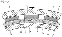
- FIGS. 10A to 10C show the generation status of magnetic circuits in a non-braking state in the deceleration device.
- FIGS. 9A and 10A are sectional views along a circumferential direction.
- FIGS. 9B and 10B are longitudinal sectional views of the deceleration devices.
- FIGS. 9C and 10C are cross-sectional views of the deceleration devices.
- the deceleration device according to the second embodiment is a modification of the first embodiment, and the second embodiment differs from the first embodiment in the switching mechanism.
- the deceleration device includes a two-row rotation switching mechanism as a switching mechanism for switching between a braking state and a non-braking state.
- the primary magnets 3A, the secondary magnets 3B and the magnet holding ring 2 are located inside the brake drum 1 at all times and are not movable in the axial direction along the axis of the rotary shaft 10.
- the array of magnets 3A and 3B is divided into a first row (C1) and a second row (C2), each of the rows extending in the circumferential direction along the circumference of a circle around the rotary shaft 10.
- the magnet holding ring 2 is divided into a first section and a second section holding the first row of magnets and the second row of magnets, respectively.
- the first row of magnets 3A and 3B and the first section of the magnet holding ring 2, and the second row of magnets 3A and 3B and the second section of the magnet holding ring 2 are located with a narrow gap in between, and are independent of each other.
- the length (dimension in the axial direction along the axis of the rotary shaft 10) of the magnets 3A in the first row is nearly equal to the length of the magnets 3A in the second row, and the length of the magnets 3B in the first row is nearly equal to the length of the magnets 3B in the second row (see FIGS. 8 , 9A , 9B , 10A and 10B ).
- a plurality of plate-like switches 4 are arrayed throughout the whole circumference of a circle around the rotary shaft 10. Unlike the array of magnets 3A, 3B and the magnetic holding ring 2, the array of switches 4 is not divided.
- the placement angles of the switches 4 are the same as the placement angles of the primary magnets 3A.
- Each of the switches 4 has a size as follows. The dimension of the switch 4 in the circumferential direction along the circumference of a circle around the rotary shaft 3 is nearly equal to that of each of the primary magnets 3A (see FIGS. 9C and 10C ).
- the dimension of the switch 4 in the axial direction along the axis of the rotary shaft 3 is nearly equal to the total of that of a primary magnet 3A in the first row and that of a primary magnet 3A in the second row (see FIGS. 9B and 10B ).
- both sides of the respective switches 4 are held by the switch holding ring 5.
- the switch holding ring 5 is fixed to the stator support 7.
- the first section of the magnetic holding ring 2 holding the first row of magnets is fixed to the rotor support 7.
- the second section of the magnetic holding ring 2 holding the second row of magnets is supported by the stator support 7 and is rotatable around the rotary shaft 10.
- a drive unit (not shown) such as an air cylinder, an electric actuator or the like is connected to the second section of the magnetic holding ring 2.
- the second section of the magnet holding ring 2 and the second row of magnets 3A and 3B are rotated together by operation of the drive unit. In this way, the deceleration device can be switched between a braking state and a non-braking state.
- a primary magnet 3A in the first row and a primary magnet 3A in the second row that have the same magnetic pole arrangement are aligned in the axial direction along the axis of the rotary shaft 10
- a secondary magnet 3B in the first row and a secondary magnet 3B in the second row that have the same magnetic pole arrangement are aligned in the axial direction (see FIGS. 9A and 9B ).
- a primary magnet 3A in the first row and a primary magnet 3A in the second row that have opposite magnetic pole arrangements are aligned in the axial direction
- a secondary magnet 3B in the first row and a secondary magnet 3B in the second row that have opposite magnetic pole arrangements are aligned in the axial direction
- the switches 4 are located over the first primary magnets 3A (see FIGS. 9C and 10C ).
- the two-row rotation switching mechanism operates to keep the magnets 3A and 3B such that a primary magnet 3A in the first row and a primary magnet 3A in the second row that have opposite magnetic pole arrangements are in alignment with each other as axially adjacent primary magnets 3A and such that a secondary magnet 3B in the first row and a secondary magnet 3B in the second row that have opposite magnetic pole arrangements are in alignment with each other as axially adjacent secondary magnets 3B, as shown in FIGS. 10A to 10C .
- the magnetic fluxes from the magnets 3A and 3B are as follows.
- a magnetic circuit as shown in FIG. 10B is formed.
- two axially adjacent primary magnets 3A a first primary magnet 3A and a second primary magnet 3A
- the magnetic flux outgoing from the north pole of the first primary magnet 3A reaches the south pole of the second primary magnet 3A via the switch 4 located over the first and the second primary magnets 3A.
- the magnetic fluxes outgoing from the north poles of the secondary magnets 3B that are in contact with the first primary magnet 3A are superimposed.
- the magnetic flux outgoing from the north pole of the second primary magnet 3A reaches the south pole of the first primary magnet 3A via the magnet holding ring 2.
- the axially adjacent primary magnets 3A form a strong magnetic circuit across the adjacent primary magnets 3A, the secondary magnet 3B that is in contact with the primary magnets 3A, the magnet holding ring 2 and the switch 4.
- Such magnetic circuits are formed throughout the whole circumference such that the directions of adjacent magnetic fluxes are opposite to each other.
- the two-row rotation switching mechanism operates to keep the magnets 3A and 3B such that a primary magnet 3A in the first row and a primary magnet 3A in the second row that have the same magnetic pole arrangement are in alignment with each other as axially adjacent primary magnets 3A and such that a secondary magnet 3A in the first row and a secondary magnet 3B in the second row that have the same magnetic pole arrangement are completely in alignment with each other as axially adjacent secondary magnets 3B.
- the magnetic fluxes from the magnets 3A and 3B are as follows.
- the magnetic flux outgoing from the north pole of the first primary magnet 3A passes through the switch 4 located over the first primary magnet 3A and reaches the brake drum 1.
- the magnetic fluxes outgoing from the north poles of the secondary magnets 3B that are in contact with the first primary magnet 3A are superimposed.
- the magnetic flux that has reached the brake drum 1 reaches the south pole of the second primary magnet 3A through the switch 4.
- the magnetic flux outgoing from the second primary magnet 3A reaches the south pole of the first primary magnet 3A via the magnet holding ring 2.
- the circumferentially adjacent primary magnets 3A form a strong magnetic circuit across the first primary magnets 3A, the secondary magnet 3B that is in contact with the primary magnets 3A, the magnet holding ring 2, the switch 4 located over the primary magnets 3A, and the brake drum 1.
- Such magnetic fields are formed throughout the whole circumference such that the directions of adjacent magnetic fluxes are opposite to each other.
- the deceleration device according to the second embodiment in the braking state, strong magnetic circuits are formed almost in the same manner as in the first embodiment. Accordingly, the deceleration device according to the second embodiment has the same advantageous effects as the first embodiment.
- the second-row rotation switching mechanism employed in the second embodiment allows the deceleration device to have a short entire length, compared with the deceleration device according to the first embodiment employing the axial motion switching mechanism. Accordingly, the second-row rotation switching mechanism is effective to downsize the device.
- the above-mentioned single-row rotation switching mechanism in which the array of magnets 3A and 3B is not divided into two rows and the magnet holding ring 2 is not divided into two sections, in the deceleration device according to the second embodiment.
- the single-row rotation switching mechanism as compared with the case where the two-row rotation switching mechanism is employed, the generation status of magnetic circuits in the braking state is almost the same, but the generation status of magnetic circuits in the non-braking state is different.
- the single-row rotation switching mechanism specifically, in the non-braking state, the switches 4 are kept in such positions that each of the switches 4 lies across two circumferentially adjacent primary magnets 3A.
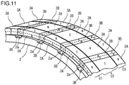
- FIG. 11 is a perspective view showing the arrangement of magnets in a deceleration device according to a third embodiment.
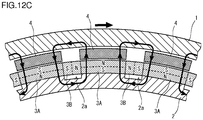
- FIGS. 12A to 12C show the generation status of magnetic circuits in a braking state in the deceleration device according to the third embodiment.
- FIGS. 13A to 13C show the generation status of magnetic circuits in a non-braking state in the deceleration device according to the third embodiment.
- FIGS. 12A and 13A are sectional views along a circumferential direction.
- FIGS. 12B and 13B are longitudinal sectional views of the deceleration device.
- FIGS. 12C and 13C are cross-sectional views of the deceleration device.
- the deceleration device according to the third embodiment is a modification of the second embodiment, and differs from the second embodiment in the switching mechanism.
- the deceleration device employs a three-row rotation switching mechanism as a switching mechanism for switching between a braking state and a non-braking state.
- the primary magnets 3A, the secondary magnets 3B and the magnet holding ring 2 are located inside the brake drum 1 at all times, and are not movable in the axial direction along the axis of the rotary shaft 10.
- the array of magnets 3A and 3B is divided into a first row (C1), a second row (C2) and a third row (C3), each of the rows extending in the circumferential direction along the circumference of the rotary shaft 10.
- the magnet holding ring 2 is divided into a first section, a second section and a third section holding the first row of magnets, the second row of magnets and the third row of magnets, respectively.
- the first row of magnets 3A and 3B and the first section of the magnet holding ring 2, the second row of magnets 3A and 3B and the second section of the magnet holding ring 2, and the third row of magnets 3A and 3B and the third section of the magnet holding ring 2 are located with narrow gaps in between, and are independent of one another.
- the length (dimension in the axial direction along the axis of the rotary shaft 10) of the primary magnets 3A in the first and the third rows is nearly equal to a half of the length of the primary magnets 3A in the second row, and the length of the secondary magnets 3B in the first and the third rows is nearly equal to a half of the length of the secondary magnets 3B in the second row (see FIGS. 11 , 12A , 12B , 13A and 13B ).
- each of the plate-like switches 4 has a size as follows.
- the dimension of the switch 4 in the circumferential direction along the circumference of the rotary shaft 10 is nearly equal to that of each of the primary magnets 3A (see FIGS. 12C and 13C ).
- the dimension of the switch 4 in the axial direction along the axis of the rotary shaft 10 is nearly equal to the total of that of a primary magnet 3A in the first row, that of a primary magnet 3A in the second row and that of a primary magnet 3A in the third row (see FIGS. 12B and 13B ).
- the first section and the third section of the magnet holding ring 2 are fixed to the stator support 7.
- the second section of the magnet holding ring 2 is supported by the stator support 7 to be rotatable around the rotary shaft 10.
- a drive unit such as an air cylinder, an electric actuator or the like is connected to the second section of the magnet holding ring 2.
- the drive unit operates to rotate the second section of the magnet holding ring 2 and the second row of magnets 3A and 3B together. Thereby, the deceleration device can be switched between a braking state and a non-braking state.
- a primary magnet 3A in the first row and a primary magnet 3A in the second row and a primary magnet 3A in the third row that have the same magnetic pole arrangement are aligned in the axial direction along the axis of the rotary shaft 10
- a secondary magnet 3B in the first row and a secondary magnet 3B in the second row and a secondary magnet 3B in the third row that have the same magnetic pole arrangement are aligned in the axial direction (see FIGS. 12A and 12B ).
- a primary magnet 3A in the first row, a primary magnet 3A in the second row and a primary magnet 3A in the third row are aligned in the axial direction such that two axially adjacent primary magnets 3A have opposite magnetic pole arrangements
- a secondary magnet 3B in the first row, a secondary magnet 3B in the second row and a secondary magnet 3B in the third row are aligned in the axial direction such that two axially adjacent secondary magnets 3B have opposite magnetic pole arrangements (see FIGS. 10A and 10B ).
- the switches 4 are located over the first primary magnets 3A (see FIGS. 12C and 13C ).
- the three-row rotation switching mechanism keeps the magnets 3A and 3B such that two axially adjacent primary magnets 3A have opposite magnetic pole arrangements and such that two axially adjacent secondary magnets 3B have opposite magnetic pole arrangements.
- the magnetic fluxes from the magnets 3A and 3B are as follows.
- the two axially adjacent primary magnets 3A, and the secondary magnet 3B that is in contact with the two primary magnets 3A form a strong magnetic circuit across the primary magnets 3A, the secondary magnet 3B, the magnetic holding ring 2 and the switch 4.
- Such magnetic circuits are formed throughout the whole circumference such that adjacent magnetic fluxes are in opposite directions.
- the magnets 3A and 3B in the second and the third rows form magnetic circuits in the same manner.
- the three-row rotation switching mechanism keeps the magnets 3A and 3B such that three axially aligned primary magnets 3A have the same magnetic pole arrangement and such that three axially aligned secondary magnets 3B have the same magnetic pole arrangement as shown in FIGS. 12A to 12C .
- the magnetic fluxes from the magnets 3A and 3B are as follows.
- the magnetic flux outgoing from the north pole of the first primary magnet 3A passes through the switch 4 located over the first primary magnet 3A and reaches the brake drum 1.
- the magnetic fluxes outgoing from the north poles of the secondary magnets 3B that are in contact with the first primary magnet 3A are superimposed.
- the magnetic flux that has reached the brake drum 1 reaches the south pole of the second primary magnet 3A through the switch 4 located over the second primary magnet 3A.
- the magnetic flux outgoing from the north pole of the second primary magnet 3A reaches the south pole of the first primary magnet 3A via the magnet holding ring 2.
- the deceleration device according to the third embodiment in the braking state and the non-braking state, magnetic circuits are formed in the same manner as in the deceleration device according to the second embodiment. Accordingly, the deceleration device according to the third embodiment has the same advantageous effects as the deceleration device according to the second embodiment.
- the magnetic fluxes from the magnets 3A and 3B in the non-braking state scatter, as compared with the case where the two-row rotation switching mechanism is employed. In the third embodiment, therefore, generation of magnetic leakage loss torque in the non-braking state can be prevented more effectively.
- the two-row rotation switching mechanism in the second embodiment may be modified as follows.
- the first section of the magnet holding ring 2 is rotatably supported by the stator support 7, and the second section of the magnet holding ring 2 is fixed to the stator support 7.
- the three-row rotation switching mechanism in the third embodiment may be modified as follows.
- the first section and the third section of the magnet holding ring 2 are rotatably supported by the stator support 7, and the second section of the magnet holding ring 2 is fixed to the stator support 7.
- the magnets 3A, 3B and the magnet holding ring 2 are located inside the brake drum 1 such that the magnets 3A and 3B face the inner peripheral surface of the brake drum 1.
- the magnets 3A, 3B and the magnet holding ring 2 may be located outside the brake drum 1 such that the magnets 3A and 3B face the outer peripheral surface of the brake drum 1. In this case, the magnets 3A and 3B are supported on the inner peripheral surface of the magnet holding ring 2.
- the non-magnetic member located between each of the secondary magnets 3B and the magnetic holding ring 2 may have a rounded-off corner on the side farther from the brake drum 1.
- FIG. 14 shows an example of such structures.
- FIG. 14 shows a section perpendicular to the rotation axis.
- the magnetic holding ring 2 shown in FIG. 14 has recessed portions (grooves) that are to become the spaces 2a, and the two corners at the bottom of each of the recessed portions are rounded-off.
- the non-magnetic member (atmospheric air) present in each of the spaces 2a has rounded-off corners at the corners 2ac on the farther side from the brake member 1.
- This structure provides an effect of preventing a magnetic flux flowing in the magnetic holding ring 2 from being interrupted by the corners of the non-magnetic member.
- the dimension in the circumferential direction of the secondary magnets 3B may decrease with decreasing distance from the brake drum 1.
- FIG. 15 shows an example of such structures.
- FIG. 15 shows a section (cross section) perpendicular to the axial direction along the rotation axis.
- each of the secondary magnets 3B is an isosceles trapezoid with the side near the brake drum 1 short, and is line symmetric with respect to a line extending radially from the rotation axis.
- the cross-sectional shape of each of the primary magnets 3A is an isosceles trapezoid with the side near the brake drum 1 long, and is line symmetric with respect to a line extending radially from the rotation axis.
- the inclined side walls of the secondary magnets 3B are pressed down by the inclined side walls of the primary magnets 3A.
- FIGS. 14 and 15 are modifications of the structure shown in FIGS. 5 to 7 .
- the structures shown in FIGS. 14 and 15 can be employed in any other deceleration device according to the present invention.
- the deceleration device according to the present invention can be effectively used as an auxiliary brake for any type of vehicle.
Landscapes
- Engineering & Computer Science (AREA)
- Power Engineering (AREA)
- Dynamo-Electric Clutches, Dynamo-Electric Brakes (AREA)
Applications Claiming Priority (2)
| Application Number | Priority Date | Filing Date | Title |
|---|---|---|---|
| JP2015119016 | 2015-06-12 | ||
| PCT/JP2016/067170 WO2016199836A1 (fr) | 2015-06-12 | 2016-06-09 | Dispositif de décélération du type à courants de foucault |
Publications (2)
| Publication Number | Publication Date |
|---|---|
| EP3309944A1 true EP3309944A1 (fr) | 2018-04-18 |
| EP3309944A4 EP3309944A4 (fr) | 2018-06-13 |
Family
ID=57503908
Family Applications (1)
| Application Number | Title | Priority Date | Filing Date |
|---|---|---|---|
| EP16807542.2A Withdrawn EP3309944A4 (fr) | 2015-06-12 | 2016-06-09 | Dispositif de décélération du type à courants de foucault |
Country Status (5)
| Country | Link |
|---|---|
| US (1) | US10756612B2 (fr) |
| EP (1) | EP3309944A4 (fr) |
| JP (1) | JP6620809B2 (fr) |
| CN (1) | CN107636943B (fr) |
| WO (1) | WO2016199836A1 (fr) |
Cited By (2)
| Publication number | Priority date | Publication date | Assignee | Title |
|---|---|---|---|---|
| FR3122405A1 (fr) * | 2021-05-03 | 2022-11-04 | Safran Landing Systems | Dispositif de freinage magnétique à courant de Foucault, roue freinée de véhicule et atterrisseur d’aéronef équipé d’une telle roue |
| FR3122404A1 (fr) * | 2021-05-03 | 2022-11-04 | Safran Landing Systems | Dispositif de freinage magnétique à courant de Foucault, roue freinée de véhicule et atterrisseur d’aéronef équipé d’une telle roue |
Families Citing this family (7)
| Publication number | Priority date | Publication date | Assignee | Title |
|---|---|---|---|---|
| CN105993119B (zh) | 2014-02-17 | 2019-06-28 | 日本制铁株式会社 | 带电力产生功能的涡流式减速装置 |
| CN203775006U (zh) * | 2014-04-11 | 2014-08-13 | 刁俊起 | 一种固定磁隙的永磁调速器 |
| CN104362829A (zh) * | 2014-12-05 | 2015-02-18 | 刁俊起 | 一种固定磁隙的永磁调速器 |
| JP6897525B2 (ja) * | 2017-11-30 | 2021-06-30 | 日本製鉄株式会社 | 渦電流式ダンパ |
| US11165326B2 (en) * | 2018-01-29 | 2021-11-02 | Nippon Steel Corporation | Eddy current decelerating apparatus |
| JP7094756B2 (ja) * | 2018-04-05 | 2022-07-04 | 株式会社免制震ディバイス | マスダンパ |
| CN114342219A (zh) * | 2019-08-28 | 2022-04-12 | 学校法人工学院大学 | 旋转电机 |
Family Cites Families (18)
| Publication number | Priority date | Publication date | Assignee | Title |
|---|---|---|---|---|
| JPH079085A (ja) | 1993-06-22 | 1995-01-13 | Masamichi Tanaka | 部分改質したアルミニウム製鋳造用中子の製造法 |
| JPH079085U (ja) * | 1993-07-05 | 1995-02-07 | 住友特殊金属株式会社 | 複合リターダ |
| JPH0992498A (ja) | 1995-09-26 | 1997-04-04 | Shin Etsu Chem Co Ltd | 挿入光源装置用磁気回路 |
| JPH1028356A (ja) * | 1996-07-10 | 1998-01-27 | Denso Corp | 回転電機の磁石式固定子の着磁方法 |
| JP2000312466A (ja) | 1999-04-26 | 2000-11-07 | Isuzu Motors Ltd | 渦電流式減速装置 |
| JP2000333389A (ja) * | 1999-05-18 | 2000-11-30 | Fujitsu General Ltd | 永久磁石電動機 |
| EP1124311B1 (fr) * | 2000-02-10 | 2009-10-21 | Sumitomo Metal Industries, Ltd | Frein à courants de Foucault |
| US6533083B1 (en) * | 2000-02-15 | 2003-03-18 | Magnetar Technologies, Inc | Eddy current braking apparatus |
| JP2002359941A (ja) * | 2001-05-30 | 2002-12-13 | Isuzu Motors Ltd | 回転電機 |
| EP1480320B1 (fr) * | 2002-02-28 | 2008-07-30 | SUMITOMO METAL INDUSTRIES, Ltd. | Reducteur de vitesse a courants de foucault |
| EP1367701B1 (fr) * | 2002-05-28 | 2009-11-04 | Isuzu Motors Limited | Ralentisseur à courant de Foucault |
| JP2004048963A (ja) | 2002-07-15 | 2004-02-12 | Sumitomo Metal Ind Ltd | 渦電流式減速装置及びそれに用いる永久磁石 |
| JP2004350427A (ja) | 2003-05-22 | 2004-12-09 | Denso Corp | 回転電機とその回転子 |
| JP3955888B2 (ja) * | 2003-12-12 | 2007-08-08 | トック・エンジニアリング株式会社 | 永久磁石式渦電流加熱装置 |
| JP2007014110A (ja) * | 2005-06-30 | 2007-01-18 | Asmo Co Ltd | 回転電機 |
| JP2007019127A (ja) * | 2005-07-06 | 2007-01-25 | Yaskawa Electric Corp | 周期磁界発生装置およびそれを用いたリニアモータ |
| JP5656719B2 (ja) | 2011-04-01 | 2015-01-21 | 三菱電機株式会社 | 永久磁石型回転電機及び永久磁石型回転電機の製造方法 |
| WO2013008284A1 (fr) * | 2011-07-08 | 2013-01-17 | 三菱電機株式会社 | Machine électrique tournante de type à aimant permanent et son procédé de fabrication |
-
2016
- 2016-06-09 EP EP16807542.2A patent/EP3309944A4/fr not_active Withdrawn
- 2016-06-09 WO PCT/JP2016/067170 patent/WO2016199836A1/fr active Application Filing
- 2016-06-09 CN CN201680033787.9A patent/CN107636943B/zh not_active Expired - Fee Related
- 2016-06-09 US US15/564,019 patent/US10756612B2/en active Active
- 2016-06-09 JP JP2017523686A patent/JP6620809B2/ja active Active
Cited By (4)
| Publication number | Priority date | Publication date | Assignee | Title |
|---|---|---|---|---|
| FR3122405A1 (fr) * | 2021-05-03 | 2022-11-04 | Safran Landing Systems | Dispositif de freinage magnétique à courant de Foucault, roue freinée de véhicule et atterrisseur d’aéronef équipé d’une telle roue |
| FR3122404A1 (fr) * | 2021-05-03 | 2022-11-04 | Safran Landing Systems | Dispositif de freinage magnétique à courant de Foucault, roue freinée de véhicule et atterrisseur d’aéronef équipé d’une telle roue |
| WO2022233863A1 (fr) * | 2021-05-03 | 2022-11-10 | Safran Landing Systems | Dispositif de freinage magnetique a courant de foucault, roue freinee de vehicule et atterrisseur d'aeronef equipe d'une telle roue |
| WO2022233865A1 (fr) * | 2021-05-03 | 2022-11-10 | Safran Landing Systems | Dispositif de freinage magnetique a courant de foucault, roue freinee de vehicule et atterrisseur d'aeronef equipe d'une telle roue |
Also Published As
| Publication number | Publication date |
|---|---|
| JPWO2016199836A1 (ja) | 2018-02-01 |
| JP6620809B2 (ja) | 2019-12-18 |
| EP3309944A4 (fr) | 2018-06-13 |
| US20180138795A1 (en) | 2018-05-17 |
| CN107636943B (zh) | 2020-02-18 |
| US10756612B2 (en) | 2020-08-25 |
| WO2016199836A1 (fr) | 2016-12-15 |
| CN107636943A (zh) | 2018-01-26 |
Similar Documents
| Publication | Publication Date | Title |
|---|---|---|
| US10756612B2 (en) | Eddy current deceleration device | |
| US20130307365A1 (en) | Automotive embedded permanent magnet rotary electric machine | |
| JP5250692B2 (ja) | 永久磁石式回転電機 | |
| EP3748824B1 (fr) | Dispositif de réduction de vitesse de type à courant de foucault | |
| JP5096756B2 (ja) | 回転電機 | |
| JP6098738B2 (ja) | 電力生成機能付き渦電流式減速装置 | |
| JP2013188075A (ja) | 永久磁石形回転電機の回転子 | |
| JP2012080608A (ja) | 回転電機のロータ | |
| JP4752414B2 (ja) | 渦電流式減速装置 | |
| JP2008017579A (ja) | 渦電流減速装置 | |
| JP2006217764A (ja) | アキシャルギャップ型回転電機 | |
| JP7290831B2 (ja) | 渦電流式減速装置 | |
| JP4752416B2 (ja) | 渦電流式減速装置 | |
| JP2020108275A (ja) | 回転電機のロータ | |
| JPWO2018116575A1 (ja) | 渦電流式減速装置 | |
| JP2004350412A (ja) | 渦電流式減速装置 | |
| JP2018121407A (ja) | アウターロータ型の回転電機 | |
| JP2005348572A (ja) | アキシャルギャップ型回転電機のロータ構造 | |
| JP2021112038A (ja) | 渦電流式減速装置 | |
| JP2007116885A (ja) | 渦電流式減速装置 | |
| JP4048778B2 (ja) | ポールピースの製造方法及びそのポールピースを用いた永久磁石式渦電流減速装置 | |
| JP6209630B2 (ja) | 回転電機の回転子 | |
| JP2005080477A (ja) | 渦電流式減速装置 | |
| JP2008029172A (ja) | 渦電流減速装置 | |
| JP2018061368A (ja) | ロータ |
Legal Events
| Date | Code | Title | Description |
|---|---|---|---|
| PUAI | Public reference made under article 153(3) epc to a published international application that has entered the european phase |
Free format text: ORIGINAL CODE: 0009012 |
|
| 17P | Request for examination filed |
Effective date: 20171129 |
|
| AK | Designated contracting states |
Kind code of ref document: A1 Designated state(s): AL AT BE BG CH CY CZ DE DK EE ES FI FR GB GR HR HU IE IS IT LI LT LU LV MC MK MT NL NO PL PT RO RS SE SI SK SM TR |
|
| AX | Request for extension of the european patent |
Extension state: BA ME |
|
| A4 | Supplementary search report drawn up and despatched |
Effective date: 20180515 |
|
| RIC1 | Information provided on ipc code assigned before grant |
Ipc: H02K 49/02 20060101AFI20180508BHEP Ipc: H02K 49/04 20060101ALI20180508BHEP |
|
| DAV | Request for validation of the european patent (deleted) | ||
| DAX | Request for extension of the european patent (deleted) | ||
| RAP1 | Party data changed (applicant data changed or rights of an application transferred) |
Owner name: NIPPON STEEL CORPORATION |
|
| 17Q | First examination report despatched |
Effective date: 20200804 |
|
| STAA | Information on the status of an ep patent application or granted ep patent |
Free format text: STATUS: THE APPLICATION HAS BEEN WITHDRAWN |
|
| 18W | Application withdrawn |
Effective date: 20200831 |