EP3260736B1 - Two-motor vehicle drive device - Google Patents
Two-motor vehicle drive device Download PDFInfo
- Publication number
- EP3260736B1 EP3260736B1 EP16752189.7A EP16752189A EP3260736B1 EP 3260736 B1 EP3260736 B1 EP 3260736B1 EP 16752189 A EP16752189 A EP 16752189A EP 3260736 B1 EP3260736 B1 EP 3260736B1
- Authority
- EP
- European Patent Office
- Prior art keywords
- motor
- shaft
- output shaft
- speed reducer
- casing
- Prior art date
- Legal status (The legal status is an assumption and is not a legal conclusion. Google has not performed a legal analysis and makes no representation as to the accuracy of the status listed.)
- Active
Links
- 239000003638 chemical reducing agent Substances 0.000 claims description 58
- 238000004891 communication Methods 0.000 claims description 8
- 238000007789 sealing Methods 0.000 claims description 3
- 238000005096 rolling process Methods 0.000 description 14
- 239000000314 lubricant Substances 0.000 description 13
- 238000005461 lubrication Methods 0.000 description 5
- 238000000034 method Methods 0.000 description 4
- 238000005192 partition Methods 0.000 description 4
- 230000007423 decrease Effects 0.000 description 3
- 230000005540 biological transmission Effects 0.000 description 2
- 230000002411 adverse Effects 0.000 description 1
- 238000013019 agitation Methods 0.000 description 1
- 239000002826 coolant Substances 0.000 description 1
- 238000001816 cooling Methods 0.000 description 1
- 230000003247 decreasing effect Effects 0.000 description 1
- 230000000694 effects Effects 0.000 description 1
- 230000008030 elimination Effects 0.000 description 1
- 238000003379 elimination reaction Methods 0.000 description 1
- 238000004519 manufacturing process Methods 0.000 description 1
- 230000000149 penetrating effect Effects 0.000 description 1
- XLYOFNOQVPJJNP-UHFFFAOYSA-N water Substances O XLYOFNOQVPJJNP-UHFFFAOYSA-N 0.000 description 1
Images


Classifications
-
- B—PERFORMING OPERATIONS; TRANSPORTING
- B60—VEHICLES IN GENERAL
- B60K—ARRANGEMENT OR MOUNTING OF PROPULSION UNITS OR OF TRANSMISSIONS IN VEHICLES; ARRANGEMENT OR MOUNTING OF PLURAL DIVERSE PRIME-MOVERS IN VEHICLES; AUXILIARY DRIVES FOR VEHICLES; INSTRUMENTATION OR DASHBOARDS FOR VEHICLES; ARRANGEMENTS IN CONNECTION WITH COOLING, AIR INTAKE, GAS EXHAUST OR FUEL SUPPLY OF PROPULSION UNITS IN VEHICLES
- B60K7/00—Disposition of motor in, or adjacent to, traction wheel
- B60K7/0007—Disposition of motor in, or adjacent to, traction wheel the motor being electric
-
- B—PERFORMING OPERATIONS; TRANSPORTING
- B60—VEHICLES IN GENERAL
- B60K—ARRANGEMENT OR MOUNTING OF PROPULSION UNITS OR OF TRANSMISSIONS IN VEHICLES; ARRANGEMENT OR MOUNTING OF PLURAL DIVERSE PRIME-MOVERS IN VEHICLES; AUXILIARY DRIVES FOR VEHICLES; INSTRUMENTATION OR DASHBOARDS FOR VEHICLES; ARRANGEMENTS IN CONNECTION WITH COOLING, AIR INTAKE, GAS EXHAUST OR FUEL SUPPLY OF PROPULSION UNITS IN VEHICLES
- B60K1/00—Arrangement or mounting of electrical propulsion units
- B60K1/02—Arrangement or mounting of electrical propulsion units comprising more than one electric motor
-
- B—PERFORMING OPERATIONS; TRANSPORTING
- B60—VEHICLES IN GENERAL
- B60K—ARRANGEMENT OR MOUNTING OF PROPULSION UNITS OR OF TRANSMISSIONS IN VEHICLES; ARRANGEMENT OR MOUNTING OF PLURAL DIVERSE PRIME-MOVERS IN VEHICLES; AUXILIARY DRIVES FOR VEHICLES; INSTRUMENTATION OR DASHBOARDS FOR VEHICLES; ARRANGEMENTS IN CONNECTION WITH COOLING, AIR INTAKE, GAS EXHAUST OR FUEL SUPPLY OF PROPULSION UNITS IN VEHICLES
- B60K17/00—Arrangement or mounting of transmissions in vehicles
- B60K17/04—Arrangement or mounting of transmissions in vehicles characterised by arrangement, location, or kind of gearing
- B60K17/043—Transmission unit disposed in on near the vehicle wheel, or between the differential gear unit and the wheel
-
- B—PERFORMING OPERATIONS; TRANSPORTING
- B60—VEHICLES IN GENERAL
- B60K—ARRANGEMENT OR MOUNTING OF PROPULSION UNITS OR OF TRANSMISSIONS IN VEHICLES; ARRANGEMENT OR MOUNTING OF PLURAL DIVERSE PRIME-MOVERS IN VEHICLES; AUXILIARY DRIVES FOR VEHICLES; INSTRUMENTATION OR DASHBOARDS FOR VEHICLES; ARRANGEMENTS IN CONNECTION WITH COOLING, AIR INTAKE, GAS EXHAUST OR FUEL SUPPLY OF PROPULSION UNITS IN VEHICLES
- B60K17/00—Arrangement or mounting of transmissions in vehicles
- B60K17/04—Arrangement or mounting of transmissions in vehicles characterised by arrangement, location, or kind of gearing
- B60K17/14—Arrangement or mounting of transmissions in vehicles characterised by arrangement, location, or kind of gearing the motor of fluid or electric gearing being disposed in or adjacent to traction wheel
-
- B—PERFORMING OPERATIONS; TRANSPORTING
- B60—VEHICLES IN GENERAL
- B60L—PROPULSION OF ELECTRICALLY-PROPELLED VEHICLES; SUPPLYING ELECTRIC POWER FOR AUXILIARY EQUIPMENT OF ELECTRICALLY-PROPELLED VEHICLES; ELECTRODYNAMIC BRAKE SYSTEMS FOR VEHICLES IN GENERAL; MAGNETIC SUSPENSION OR LEVITATION FOR VEHICLES; MONITORING OPERATING VARIABLES OF ELECTRICALLY-PROPELLED VEHICLES; ELECTRIC SAFETY DEVICES FOR ELECTRICALLY-PROPELLED VEHICLES
- B60L15/00—Methods, circuits, or devices for controlling the traction-motor speed of electrically-propelled vehicles
- B60L15/20—Methods, circuits, or devices for controlling the traction-motor speed of electrically-propelled vehicles for control of the vehicle or its driving motor to achieve a desired performance, e.g. speed, torque, programmed variation of speed
-
- F—MECHANICAL ENGINEERING; LIGHTING; HEATING; WEAPONS; BLASTING
- F16—ENGINEERING ELEMENTS AND UNITS; GENERAL MEASURES FOR PRODUCING AND MAINTAINING EFFECTIVE FUNCTIONING OF MACHINES OR INSTALLATIONS; THERMAL INSULATION IN GENERAL
- F16H—GEARING
- F16H1/00—Toothed gearings for conveying rotary motion
- F16H1/02—Toothed gearings for conveying rotary motion without gears having orbital motion
- F16H1/04—Toothed gearings for conveying rotary motion without gears having orbital motion involving only two intermeshing members
- F16H1/06—Toothed gearings for conveying rotary motion without gears having orbital motion involving only two intermeshing members with parallel axes
-
- F—MECHANICAL ENGINEERING; LIGHTING; HEATING; WEAPONS; BLASTING
- F16—ENGINEERING ELEMENTS AND UNITS; GENERAL MEASURES FOR PRODUCING AND MAINTAINING EFFECTIVE FUNCTIONING OF MACHINES OR INSTALLATIONS; THERMAL INSULATION IN GENERAL
- F16H—GEARING
- F16H57/00—General details of gearing
- F16H57/02—Gearboxes; Mounting gearing therein
- F16H57/021—Shaft support structures, e.g. partition walls, bearing eyes, casing walls or covers with bearings
-
- F—MECHANICAL ENGINEERING; LIGHTING; HEATING; WEAPONS; BLASTING
- F16—ENGINEERING ELEMENTS AND UNITS; GENERAL MEASURES FOR PRODUCING AND MAINTAINING EFFECTIVE FUNCTIONING OF MACHINES OR INSTALLATIONS; THERMAL INSULATION IN GENERAL
- F16H—GEARING
- F16H57/00—General details of gearing
- F16H57/02—Gearboxes; Mounting gearing therein
- F16H57/029—Gearboxes; Mounting gearing therein characterised by means for sealing the gearboxes, e.g. to improve airtightness
-
- F—MECHANICAL ENGINEERING; LIGHTING; HEATING; WEAPONS; BLASTING
- F16—ENGINEERING ELEMENTS AND UNITS; GENERAL MEASURES FOR PRODUCING AND MAINTAINING EFFECTIVE FUNCTIONING OF MACHINES OR INSTALLATIONS; THERMAL INSULATION IN GENERAL
- F16H—GEARING
- F16H57/00—General details of gearing
- F16H57/04—Features relating to lubrication or cooling or heating
- F16H57/042—Guidance of lubricant
- F16H57/043—Guidance of lubricant within rotary parts, e.g. axial channels or radial openings in shafts
-
- H—ELECTRICITY
- H02—GENERATION; CONVERSION OR DISTRIBUTION OF ELECTRIC POWER
- H02K—DYNAMO-ELECTRIC MACHINES
- H02K5/00—Casings; Enclosures; Supports
- H02K5/04—Casings or enclosures characterised by the shape, form or construction thereof
- H02K5/10—Casings or enclosures characterised by the shape, form or construction thereof with arrangements for protection from ingress, e.g. water or fingers
-
- H—ELECTRICITY
- H02—GENERATION; CONVERSION OR DISTRIBUTION OF ELECTRIC POWER
- H02K—DYNAMO-ELECTRIC MACHINES
- H02K7/00—Arrangements for handling mechanical energy structurally associated with dynamo-electric machines, e.g. structural association with mechanical driving motors or auxiliary dynamo-electric machines
- H02K7/003—Couplings; Details of shafts
-
- H—ELECTRICITY
- H02—GENERATION; CONVERSION OR DISTRIBUTION OF ELECTRIC POWER
- H02K—DYNAMO-ELECTRIC MACHINES
- H02K7/00—Arrangements for handling mechanical energy structurally associated with dynamo-electric machines, e.g. structural association with mechanical driving motors or auxiliary dynamo-electric machines
- H02K7/10—Structural association with clutches, brakes, gears, pulleys or mechanical starters
- H02K7/116—Structural association with clutches, brakes, gears, pulleys or mechanical starters with gears
-
- B—PERFORMING OPERATIONS; TRANSPORTING
- B60—VEHICLES IN GENERAL
- B60K—ARRANGEMENT OR MOUNTING OF PROPULSION UNITS OR OF TRANSMISSIONS IN VEHICLES; ARRANGEMENT OR MOUNTING OF PLURAL DIVERSE PRIME-MOVERS IN VEHICLES; AUXILIARY DRIVES FOR VEHICLES; INSTRUMENTATION OR DASHBOARDS FOR VEHICLES; ARRANGEMENTS IN CONNECTION WITH COOLING, AIR INTAKE, GAS EXHAUST OR FUEL SUPPLY OF PROPULSION UNITS IN VEHICLES
- B60K11/00—Arrangement in connection with cooling of propulsion units
- B60K11/02—Arrangement in connection with cooling of propulsion units with liquid cooling
-
- B—PERFORMING OPERATIONS; TRANSPORTING
- B60—VEHICLES IN GENERAL
- B60K—ARRANGEMENT OR MOUNTING OF PROPULSION UNITS OR OF TRANSMISSIONS IN VEHICLES; ARRANGEMENT OR MOUNTING OF PLURAL DIVERSE PRIME-MOVERS IN VEHICLES; AUXILIARY DRIVES FOR VEHICLES; INSTRUMENTATION OR DASHBOARDS FOR VEHICLES; ARRANGEMENTS IN CONNECTION WITH COOLING, AIR INTAKE, GAS EXHAUST OR FUEL SUPPLY OF PROPULSION UNITS IN VEHICLES
- B60K1/00—Arrangement or mounting of electrical propulsion units
- B60K2001/003—Arrangement or mounting of electrical propulsion units with means for cooling the electrical propulsion units
- B60K2001/006—Arrangement or mounting of electrical propulsion units with means for cooling the electrical propulsion units the electric motors
-
- B—PERFORMING OPERATIONS; TRANSPORTING
- B60—VEHICLES IN GENERAL
- B60K—ARRANGEMENT OR MOUNTING OF PROPULSION UNITS OR OF TRANSMISSIONS IN VEHICLES; ARRANGEMENT OR MOUNTING OF PLURAL DIVERSE PRIME-MOVERS IN VEHICLES; AUXILIARY DRIVES FOR VEHICLES; INSTRUMENTATION OR DASHBOARDS FOR VEHICLES; ARRANGEMENTS IN CONNECTION WITH COOLING, AIR INTAKE, GAS EXHAUST OR FUEL SUPPLY OF PROPULSION UNITS IN VEHICLES
- B60K7/00—Disposition of motor in, or adjacent to, traction wheel
- B60K2007/0046—Disposition of motor in, or adjacent to, traction wheel the motor moving together with the vehicle body, i.e. moving independently from the wheel axle
-
- B—PERFORMING OPERATIONS; TRANSPORTING
- B60—VEHICLES IN GENERAL
- B60K—ARRANGEMENT OR MOUNTING OF PROPULSION UNITS OR OF TRANSMISSIONS IN VEHICLES; ARRANGEMENT OR MOUNTING OF PLURAL DIVERSE PRIME-MOVERS IN VEHICLES; AUXILIARY DRIVES FOR VEHICLES; INSTRUMENTATION OR DASHBOARDS FOR VEHICLES; ARRANGEMENTS IN CONNECTION WITH COOLING, AIR INTAKE, GAS EXHAUST OR FUEL SUPPLY OF PROPULSION UNITS IN VEHICLES
- B60K7/00—Disposition of motor in, or adjacent to, traction wheel
- B60K2007/0092—Disposition of motor in, or adjacent to, traction wheel the motor axle being coaxial to the wheel axle
-
- B—PERFORMING OPERATIONS; TRANSPORTING
- B60—VEHICLES IN GENERAL
- B60Y—INDEXING SCHEME RELATING TO ASPECTS CROSS-CUTTING VEHICLE TECHNOLOGY
- B60Y2306/00—Other features of vehicle sub-units
- B60Y2306/03—Lubrication
-
- B—PERFORMING OPERATIONS; TRANSPORTING
- B60—VEHICLES IN GENERAL
- B60Y—INDEXING SCHEME RELATING TO ASPECTS CROSS-CUTTING VEHICLE TECHNOLOGY
- B60Y2410/00—Constructional features of vehicle sub-units
- B60Y2410/10—Housings
-
- Y—GENERAL TAGGING OF NEW TECHNOLOGICAL DEVELOPMENTS; GENERAL TAGGING OF CROSS-SECTIONAL TECHNOLOGIES SPANNING OVER SEVERAL SECTIONS OF THE IPC; TECHNICAL SUBJECTS COVERED BY FORMER USPC CROSS-REFERENCE ART COLLECTIONS [XRACs] AND DIGESTS
- Y02—TECHNOLOGIES OR APPLICATIONS FOR MITIGATION OR ADAPTATION AGAINST CLIMATE CHANGE
- Y02T—CLIMATE CHANGE MITIGATION TECHNOLOGIES RELATED TO TRANSPORTATION
- Y02T10/00—Road transport of goods or passengers
- Y02T10/60—Other road transportation technologies with climate change mitigation effect
- Y02T10/72—Electric energy management in electromobility
Definitions
- the present invention relates to a two-motor vehicle-driving apparatus to be mounted above vehicle springs, including two electric motors each for driving one of a left and a right driving wheels of the vehicle independently from each other, and speed reducers.
- Patent Literature 1 disclose two-motor vehicle-driving apparatuses, each composed of: two electric motors each for driving one of a left and a right driving wheels independently from each other, and speed reducers.
- a two-motor vehicle-driving apparatus of this kind which has electric motors for driving each of the left and the right driving wheels independently, provides an advantage over a case where driving power from a single electric motor is divided to left and right for driving the left and the right wheels, that the apparatus can provide two times the power and therefore the electric motors can be smaller and lighter.
- a two-motor vehicle-driving apparatus provides another advantage that unlike a one-motor vehicle-driving apparatus in which a single electric motor must drive both the left and the right driving wheels, it does not require differential gears and others for dividing the driving power from a single electric motor to left and right.
- a conventional two-motor vehicle-driving apparatus such as disclosed in Patent Literature 1 or Patent Literature 2 includes, as shown in Fig. 5 and Fig. 6 , electric motors 101L, 101R each for independently driving one of the left and right driving wheels; and speed reducers 102L, 102R each for reducing rotation speed of a corresponding one of the electric motors 101L, 101R.
- each of the speed reducers 102L, 102R is provided by a parallel-shaft gear speed reducer in which an input shaft 123 having an input gear for receiving driving power from a motor shaft 112 and an output shaft 125 for transmitting the driving power to the driving wheel via a drive shaft 116 are disposed in parallel with each other in an offset fashion.
- one or more intermediate shaft(s) 124 are provided.
- Patent Literature 2 discloses a two-motor vehicle-driving apparatus shown in Fig. 6 , where motor shafts 112 of the electric motors 101L, 101R and input shafts 123 of the speed reducers 102L, 102R are separate members from each other, each of these shafts is individually supported with bearings, and an oil seal 126 is provided between the motor shaft 112 and a casing.
- the arrangement has a problem that it increases an axial dimension of the two-motor vehicle-driving apparatus.
- the oil seals 126 are useful in preventing lubricant, which provides lubrication of gears in the speed reducers 102L, 102R, from entering inside the electric motors 101L, 101R, the oil seal 126 has an oil seal lip which makes contact with the motor shaft 112 that is a part which has the fastest rotating speed. This decreases transmission efficiency of the two-motor vehicle-driving apparatus while increasing risk for damage, such as wear and burn of the oil seal lip.
- the present invention provides a two-motor vehicle-driving apparatus including: two electric motors for driving a left and a right wheel respectively; and two speed reducers for reducing motor rotation of respective electric motors.
- the two electric motors are disposed at locations closer to the respective wheels relative to the speed reducers.
- a motor shaft of the electric motor has an axial-through hollow structure.
- the motor shaft is provided with an input gear integrally therewith at its end closer to the speed reducer, with an output shaft provided inside the hollow motor shaft coaxially therewith.
- the output shaft has an output gear integrally therewith at its end closer to the speed reducer.
- the speed reducer is provided with one or more intermediate shafts rotatably in parallel with the motor shaft and the output shaft, and the intermediate shaft(s) is (are) provided with a plurality of gears integrally therewith for engagement with the input gear of the motor shaft and with the output gear of the output shaft to transmit rotation of the motor shaft to the output shaft at a reduced speed.
- the output shaft inside the hollow motor shaft coaxially therewith as described above, it is possible to decrease the size of the speed reducer in its radial direction.
- the output shaft which is disposed inside the hollow motor shaft coaxially therewith, has its end extending out of an opening in an outboard wall of a motor casing which houses the electric motor; and sealing is provided between the output shaft and the motor casing by an oil seal, it is possible to minimize the number of oil seals to seal lubricant filled in the speed reducer, and to provide a structure where the oil seal makes contact only with the slowest rotating shaft.
- All of the gears inside the speed reducer are provided by external gears. This makes it possible to provide lubrication by splashing lubricant with gears from a bottom reservoir in an inside space of the speed reducer.
- the output shaft is formed, inside therein, with an axial oil path which has an opening on a side closer to the speed reducer (inboard side of the apparatus). Further, one or more radial oil paths are formed to provide communication between the axial oil path and an outer circumferential regions near a bearing which supports the output shaft.
- lubricant which follows wall surfaces of the speed reducer casing and enters the inside space of the output shaft, is carried centrifugally to near the bearings through the radial oil paths by the rotation of the output shaft.
- the arrangement makes it possible to prevent damage on the bearings and the oil seals which are disposed at the outboard end regions.
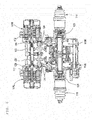
- a two-motor vehicle-driving apparatus A utilizes a structure that a speed reducer casing 20, which houses two speed reducers 2L, 2R provided side by side on left and right, is disposed at a center; and motor casings 3L, 3R of two electric motors 1L, 1R are fixed to a left side and a right side respectively of the speed reducer casing 20.
- an electric vehicle B includes a chassis 51; front wheels 52 as driving wheels; rear wheels 53; and the two-motor vehicle-driving apparatus A which drives the left and the right front wheels 52 independently from each other.
- the two-motor vehicle-driving apparatus A is mounted on the chassis 51, at a center position between the left and the right front wheels 52. Driving power from the two-motor vehicle-driving apparatus A are transmitted to the left and the right front wheels 52 via constant velocity joints 15 and drive shafts 16.
- the two-motor vehicle-driving apparatus A may be utilized in whichever of a front-wheel driving method as shown in Fig. 4 , a rear-wheel drive method and a four-wheel drive method.
- the speed reducer casing 20 which houses the two speed reducers 2L, 2R provided side by side on left and right, has a three-piece structure, including a center casing 20a, and a left and a right side casings 20bL, 20bR which are fixed to respective sides of the center casing 20a.
- the left and the right electric motors 1L, 1R in the two-motor vehicle-driving apparatus A according to the present invention are housed in the motor casings 3L, 3R.
- the motor casings 3L, 3R respectively have cylindrical motor casing main bodies 3aL, 3aR, and outboard walls 3bL, 3bR which close outboard side faces of the motor casing main bodies 3aL, 3aR.
- Each of the outboard walls 3bL, 3bR is provided with an opening 5 for an output shaft 25, which will be described later, to extend therefrom.
- inboard faces of the motor casing main bodies 3aL, 3aR, which are close to the respective speed reducers 2L, 2R are closed by the side casings 20bL, 20bR of the speed reducer casing 20.
- the motor casing main bodies 3aL, 3aR are provided with cooling piping 4, and the piping 4 is supplied with coolant from a radiator (not illustrated).
- the piping 4 constitutes so called water jacket, whereby the electric motors 1L, 1R are effectively cooled.
- the electric motors 1L, 1R are provided by radial gap motors wherein each of the motor casing main bodies 3aL, 3aR has their inner circumferential surface provided with a stator 11, and the stator 11 has its inner circumference provided with a rotor 12 at a distance.
- the rotor 12 has a motor shaft 12a at its center.
- the motor shaft 12a has an axial-through hollow structure, and each motor shaft 12a has an end penetrating corresponding one of the side casings 20bL, 20bR of the speed reducer casing 20, and inserted into the speed reducer casing 20.
- the end of the motor shaft 12a inside the speed reducer casing 20 has its outer circumferential surface provided with an input gear 23.
- the input gear 23 is formed integrally with the motor shaft 12a, at an end thereof, on an outer circumferential surface thereof; however, the input gear 23 may be fitted around the motor shaft 12a by means of splines for example.
- the motor shafts 12a are rotatably supported by the outboard walls 3bL, 3bR of the motor casings 3L, 3R and the side casings 20bL, 20bR of the speed reducer casing 20 via rolling bearings 14a, 14b ( Fig. 1 ).
- an output shaft 25 is disposed coaxially therewith.
- the output shaft 25 has a large-diameter output gear 25a inside the speed reducer casing 20, and is rotatably supported by the opening 5 in a corresponding one of the outboard walls 3bL, 3bR of the motor casings 3L, 3R and a boss portion 35 formed on both surfaces of a partition wall 21 of the center casing 20a, via rolling bearings 37a, 37b.
- the output gear 25a is spline-connected to the output shaft 25.
- an oil seal 39 is provided for sealing between the output shaft 25 and the opening 5 in each of the outboard walls 3bL, 3bR of the motor casings 3L, 3R.
- the output shaft 25 has its outboard end region fitted with a constant velocity joints 15, for transmission of driving power to the wheel 52 via a drive shaft 16.
- a support bearing 31 is provided on an inner circumferential region inside the hollow motor shaft 12a for supporting the output shaft 25 with respect to the motor shaft 12a.
- the support bearing 31 is provided by a cylindrical roller bearing. Also, in Fig. 1 , the support bearing 31 rotatably supports the output shaft 25 on an inner circumferential side of the input gear 23. The arrangement is effective in not adversely affecting the input gear 23 in terms of durability and vibration characteristics.
- the support bearing 31 is provided by a cylindrical roller bearing; however, this is not limiting.
- any of the bearings disposed in other locations may be provided by whatsoever type.
- One of the support bearing 31 and the rolling bearings 37a, 37b of the output shaft 25 may be eliminated if the elimination still ensures satisfactory support rigidity.
- Each of the speed reducers 2L, 2R is provided with one or more intermediate shafts 24 rotatably in parallel with the motor shaft 12a and the output shaft 25.
- the intermediate shaft 24 is provided with a plurality of gears integrally therewith, and these gears engage with the input gear 23 of the motor shaft 12a and the output gear 25a of the output shaft 25, to slow rotation of the motor shaft 12a before the rotation is transmitted to the output shaft 25.
- the intermediate shaft 24 is provided by a stepped gear which has, on its outer circumferential surface, a large-diameter gear 24a for engagement with the input gear 23, and a small-diameter gear 24b for engagement with the output gear 25a.
- the intermediate shaft 24 is supported, at its two ends, by a boss portion 32 formed in each surface of the partition wall 21 of the center casing 20a and by a boss portion 33 formed in each of the side casings 20bL, 20bR, via rolling bearings 34a, 34b.
- All gears inside the speed reducer casing 20 are provided by external gears, and these gears and bearings inside the speed reducer casing 20 are lubricated by splashing lubricant with gears from a bottom reservoir in the inside space of the speed reducer casing 20.
- lubricant is supplied from an axial center of the output shaft 25.
- the output shaft 25 is formed, inside thereof, with an axial oil path 6 opening at the side of the speed reducer casing 20 (inboard side of the apparatus). Further, radial oil paths 7 are formed to provide communication from the axial oil path 6 to outer circumferential regions near the rolling bearing 37a and the support bearing 31 which support the output shaft 25. Lubricant, which follows wall surfaces of the speed reducer casing and enters the inside space of the output shaft, is carried centrifugally to near the bearings through the radial oil paths by the rotation of the output shaft.
- This lubrication method by means of the axial oil paths 6 and the radial oil paths 7 makes it possible to prevent damage on the bearings and the oil seals 39 which are disposed at the outboard end regions.
- lubricant is supplied to the axial oil path 6 with flowing down on the partition wall 21 after splashed with gears from a bottom reservoir in the inside space of the speed reducer casing 20.
- An oil path which provides communication between these two spaces 9a, 9b is provided near the lowest region (Bottom Dead Center) of the stator 11.
- an axially groove 10a is provided on an outer circumference of the stator 11 or on an inner circumference of each motor casings 3L, 3R, as the path which provides communication between the spaces 9a, 9b.
- a through oil path 10b is provided in each of the side casings 20bL, 20bR which separate the motor casings 3L, 3R from the speed reducer casing 20. As shown in Fig. 2 , these through oil paths 10b are at a lower position than the lowest region (Bottom Dead Center) of the rotor 12.
- the axial grooves 10a serving as the paths which provide communication between the spaces 9a, 9b, and the through oil paths 10b which are at a lower position than the lowest point (Bottom Dead Center) of the rotors 12 allow lubricant which is supplied to the bearings and the oil seals 39 disposed at the outboard ends to move from the spaces 9a to the spaces 9b in the motor casings 3L, 3R, and then to return into the speed reducer casing 20 without being splashed by the rotor 12.
- Fig. 3 is a sectional view taken in lines III-III in Fig. 1 .
- rotation is transmitted from the input gear 23 to the large-diameter gear 24a of the intermediate shaft 24, and then from the small-diameter gear 24b of the intermediate shaft to the output gear 25a which is on the output shaft 25, whereby rotation of the electric motors 1L, 1R is slowed and transmitted to the output shafts 25, to drive the wheels 52 at a large torque.
Landscapes
- Engineering & Computer Science (AREA)
- General Engineering & Computer Science (AREA)
- Mechanical Engineering (AREA)
- Transportation (AREA)
- Chemical & Material Sciences (AREA)
- Combustion & Propulsion (AREA)
- Power Engineering (AREA)
- General Details Of Gearings (AREA)
- Connection Of Motors, Electrical Generators, Mechanical Devices, And The Like (AREA)
- Gear Transmission (AREA)
- Arrangement Or Mounting Of Propulsion Units For Vehicles (AREA)
- Electric Propulsion And Braking For Vehicles (AREA)
Applications Claiming Priority (2)
| Application Number | Priority Date | Filing Date | Title |
|---|---|---|---|
| JP2015030835A JP2016151347A (ja) | 2015-02-19 | 2015-02-19 | 2モータ車両駆動装置 |
| PCT/JP2016/051635 WO2016132800A1 (ja) | 2015-02-19 | 2016-01-21 | 2モータ車両駆動装置 |
Publications (3)
| Publication Number | Publication Date |
|---|---|
| EP3260736A1 EP3260736A1 (en) | 2017-12-27 |
| EP3260736A4 EP3260736A4 (en) | 2018-10-24 |
| EP3260736B1 true EP3260736B1 (en) | 2021-03-31 |
Family
ID=56688941
Family Applications (1)
| Application Number | Title | Priority Date | Filing Date |
|---|---|---|---|
| EP16752189.7A Active EP3260736B1 (en) | 2015-02-19 | 2016-01-21 | Two-motor vehicle drive device |
Country Status (5)
| Country | Link |
|---|---|
| US (1) | US20180015815A1 (zh) |
| EP (1) | EP3260736B1 (zh) |
| JP (1) | JP2016151347A (zh) |
| CN (1) | CN107250604A (zh) |
| WO (1) | WO2016132800A1 (zh) |
Families Citing this family (40)
| Publication number | Priority date | Publication date | Assignee | Title |
|---|---|---|---|---|
| JP6621997B2 (ja) * | 2015-04-17 | 2019-12-18 | Ntn株式会社 | 自動車用減速機付きモータ駆動装置 |
| WO2016201705A1 (en) * | 2015-06-19 | 2016-12-22 | Robert Bosch Gmbh | Electric vehicle and driving system for electric vehicle |
| JP2017047698A (ja) * | 2015-08-31 | 2017-03-09 | Ntn株式会社 | 電気自動車 |
| DE102016222844A1 (de) * | 2016-11-21 | 2018-05-24 | Audi Ag | Reibungsoptimiertes elektrisches Antriebssystem |
| CN106956579B (zh) * | 2017-05-08 | 2023-12-01 | 重庆大学 | 中空电机式电动汽车驱动切换及传动变速系统 |
| US10500941B2 (en) | 2017-08-18 | 2019-12-10 | Arvinmeritor Technology, Llc | Axle assembly having an electric motor module and a shift mechanism |
| US11273700B2 (en) * | 2017-08-18 | 2022-03-15 | Arvinmeritor Technology, Llc | Axle assembly having an electric motor module |
| US10500940B2 (en) | 2017-08-18 | 2019-12-10 | Arvinmeritor Technology, Llc | Axle assembly having an electric motor module and a gear reduction module |
| US10967927B2 (en) | 2017-09-22 | 2021-04-06 | Link Mfg., Ltd. | Mounting brackets for auxiliary suspension systems |
| JP6852810B2 (ja) * | 2017-11-17 | 2021-03-31 | アイシン・エィ・ダブリュ株式会社 | 車両用駆動装置 |
| CN111146902A (zh) * | 2018-11-03 | 2020-05-12 | 达尼克有限责任公司 | 机电驱动设备、制动系统和电池管理系统 |
| KR102111472B1 (ko) * | 2018-11-08 | 2020-05-15 | 김만식 | 전기 자동차용 감속기 |
| US10704597B2 (en) | 2018-11-30 | 2020-07-07 | Arvinmeritor Technology, Llc | Axle assembly having a bearing preload module |
| US10985635B2 (en) | 2018-11-30 | 2021-04-20 | Arvinmeritor Technology, Llc | Axle assembly having a resolver and a method of assembly |
| US10808834B2 (en) | 2018-11-30 | 2020-10-20 | Arvinmeritor Technology, Llc | Axle assembly and method of control |
| US10935120B2 (en) | 2018-11-30 | 2021-03-02 | Arvinmeritor Technology, Llc | Axle assembly having a spigot bearing assembly |
| US11038396B2 (en) | 2018-11-30 | 2021-06-15 | Arvinmeritor Technology, Llc | Axle assembly having an electric motor module and method of assembly |
| US10801602B2 (en) | 2018-11-30 | 2020-10-13 | Arvinmeritor Technology, Llc | Axle assembly having counterphase planet gears |
| US10808830B2 (en) | 2018-11-30 | 2020-10-20 | Arvinmeritor Technology, Llc | Axle assembly with multiple lubricant chambers |
| EP3663118A1 (en) * | 2018-12-04 | 2020-06-10 | AVL MTC Motortestcenter AB | Transmission arrangement for a drive system of a vehicle |
| JP2020139613A (ja) * | 2019-03-01 | 2020-09-03 | 本田技研工業株式会社 | 出力シャフト支持構造及び出力シャフトの組立方法 |
| JP7172824B2 (ja) * | 2019-04-16 | 2022-11-16 | 株式会社デンソー | 回転式アクチュエータ |
| EP3973210A1 (de) | 2019-07-09 | 2022-03-30 | hofer powertrain innovation GmbH | Doppelgetriebe |
| DE202019103771U1 (de) * | 2019-07-09 | 2020-10-13 | Hofer Powertrain Innovation Gmbh | Doppelgetriebe, insbesondere für einen elektromotorischen Antriebsstrang, mit einer Stützstruktur sowie dazugehörige Lagerbrille |
| DE202019103778U1 (de) * | 2019-07-09 | 2020-10-12 | Hofer Powertrain Innovation Gmbh | Getriebe, insbesondere verblocktes Einzelradgetriebe mit Entlüftung und verringerter Gefahr des Ölaustritts |
| EP3784929A1 (de) | 2019-07-09 | 2021-03-03 | hofer powertrain innovation GmbH | Getriebe, insbesondere twin-getriebe, und lagerbrille mit einer vorteilhaften ölschmierung durch ein mehrkammernsystem sowie geeignetes verfahren zum schmieren eines solchen getriebes |
| CN110581624A (zh) * | 2019-08-21 | 2019-12-17 | 珠海格力电器股份有限公司 | 无轴端输出电机、新能源汽车 |
| US11209072B2 (en) | 2019-10-07 | 2021-12-28 | Arvinmeritor Technology, Llc | Axle assembly having a multi-speed transmission |
| US11207976B2 (en) | 2019-10-07 | 2021-12-28 | Arvinmeritor Technology, Llc | Axle assembly having a multi-speed countershaft transmission |
| US11441644B2 (en) | 2019-10-07 | 2022-09-13 | Arvinmeritor Technology, Llc | Axle assembly having a multi-speed transmission and a drop gear set |
| US10989288B1 (en) | 2019-10-07 | 2021-04-27 | Arvinmeritor Technology, Llc | Axle assembly having a multi-speed countershaft transmission |
| US11413947B2 (en) * | 2019-12-18 | 2022-08-16 | GM Global Technology Operations LLC | Bearing and shaft arrangement for electric drive unit |
| CN111016629A (zh) * | 2019-12-31 | 2020-04-17 | 西南大学 | 中央驱动的双电机集成化动力系统 |
| CN111762010A (zh) * | 2020-07-07 | 2020-10-13 | 精进电动科技股份有限公司 | 一种双电机驱动系统 |
| DE102020122246A1 (de) | 2020-08-26 | 2022-03-03 | Schaeffler Technologies AG & Co. KG | Elektrische Maschinenanordnung |
| CN114374290A (zh) * | 2020-10-14 | 2022-04-19 | 采埃孚股份公司 | 电驱动装置 |
| US11608877B2 (en) | 2021-02-22 | 2023-03-21 | Arvinmeritor Technology, Llc | Axle assembly having a sector cam |
| US11371588B1 (en) | 2021-02-22 | 2022-06-28 | Arvinmeritor Technology, Llc | Axle assembly having a barrel cam |
| DE102021206732A1 (de) | 2021-06-29 | 2022-12-29 | Zf Friedrichshafen Ag | Antriebsanordnung für ein Fahrzeug |
| EP4366962A1 (en) * | 2021-07-08 | 2024-05-15 | Link MFG., Ltd. | Driven lift axles and associated systems and methods |
Family Cites Families (11)
| Publication number | Priority date | Publication date | Assignee | Title |
|---|---|---|---|---|
| JP4474173B2 (ja) * | 2004-02-16 | 2010-06-02 | トヨタ自動車株式会社 | 電動輪 |
| JP2007161022A (ja) * | 2005-12-12 | 2007-06-28 | Bridgestone Corp | インホイールモータシステム |
| CN200939826Y (zh) * | 2006-08-11 | 2007-08-29 | 郭广荣 | 一种双电机输出轴车桥总成 |
| DE102009033531A1 (de) * | 2009-07-10 | 2011-01-20 | Dr. Ing. H.C. F. Porsche Aktiengesellschaft | Antriebsvorrichtung für ein Kraftfahrzeug mit einer elektrische Maschinen aufweisenden Portalachse |
| JP2011240772A (ja) * | 2010-05-17 | 2011-12-01 | Ntn Corp | インホイールモータ駆動装置 |
| US9080659B2 (en) * | 2011-01-11 | 2015-07-14 | Jtekt Corporation | In-wheel motor driving device |
| JP2012228143A (ja) * | 2011-04-22 | 2012-11-15 | Aisin Aw Co Ltd | 電動車両用駆動装置 |
| EP2720352B1 (en) * | 2011-06-07 | 2019-08-07 | Honda Motor Co., Ltd. | Drive device for vehicle |
| JP5647946B2 (ja) * | 2011-06-07 | 2015-01-07 | 本田技研工業株式会社 | 車両用駆動装置 |
| JP5469700B2 (ja) * | 2012-04-02 | 2014-04-16 | Ntn株式会社 | インホイールモータ駆動装置 |
| CN204641379U (zh) * | 2015-03-05 | 2015-09-16 | 腾达电动科技镇江有限公司 | 电动车轮毂电机双轮驱动系统 |
-
2015
- 2015-02-19 JP JP2015030835A patent/JP2016151347A/ja active Pending
-
2016
- 2016-01-21 WO PCT/JP2016/051635 patent/WO2016132800A1/ja active Application Filing
- 2016-01-21 EP EP16752189.7A patent/EP3260736B1/en active Active
- 2016-01-21 CN CN201680011006.6A patent/CN107250604A/zh active Pending
- 2016-01-21 US US15/546,520 patent/US20180015815A1/en not_active Abandoned
Non-Patent Citations (1)
| Title |
|---|
| None * |
Also Published As
| Publication number | Publication date |
|---|---|
| WO2016132800A1 (ja) | 2016-08-25 |
| CN107250604A (zh) | 2017-10-13 |
| US20180015815A1 (en) | 2018-01-18 |
| JP2016151347A (ja) | 2016-08-22 |
| EP3260736A4 (en) | 2018-10-24 |
| EP3260736A1 (en) | 2017-12-27 |
Similar Documents
| Publication | Publication Date | Title |
|---|---|---|
| EP3260736B1 (en) | Two-motor vehicle drive device | |
| US11155161B2 (en) | Motor drive device for automobile and equipped with speed reducer | |
| US10378641B2 (en) | Power system | |
| US10207572B2 (en) | Two-motor vehicle drive device | |
| US10871091B2 (en) | Power system | |
| KR101949381B1 (ko) | 인휠 모터 유닛 | |
| JP6670118B2 (ja) | 車両駆動装置 | |
| JP2008184111A (ja) | 車輪駆動装置 | |
| JP6933775B2 (ja) | 車両用パワーユニット | |
| WO2017026258A1 (ja) | 車両用モータ駆動装置 | |
| JP2017141881A (ja) | 車両駆動装置 | |
| JP2016180424A (ja) | 車両駆動装置 | |
| JP2016175563A (ja) | 2モータ車両駆動装置 | |
| WO2019177104A1 (ja) | 車両駆動装置 | |
| JP2016217460A (ja) | 2モータ車両駆動装置 | |
| JP2018053996A (ja) | 2モータ車両駆動装置 | |
| JP2017061959A (ja) | 車両駆動装置 | |
| JP2018100748A (ja) | 動力装置 | |
| JP2016188651A (ja) | 2モータ車両駆動装置 | |
| JP2017057961A (ja) | 車両駆動装置 | |
| JP2017036795A (ja) | 車両用モータ駆動装置 | |
| JP2020165443A (ja) | ディファレンシャル装置及びディファレンシャル装置の製品群 | |
| JP2018048670A (ja) | 車両駆動装置 | |
| JP2021133772A (ja) | トランスアクスル | |
| JP2017057987A (ja) | 車両用モータ駆動装置 |
Legal Events
| Date | Code | Title | Description |
|---|---|---|---|
| STAA | Information on the status of an ep patent application or granted ep patent |
Free format text: STATUS: THE INTERNATIONAL PUBLICATION HAS BEEN MADE |
|
| PUAI | Public reference made under article 153(3) epc to a published international application that has entered the european phase |
Free format text: ORIGINAL CODE: 0009012 |
|
| STAA | Information on the status of an ep patent application or granted ep patent |
Free format text: STATUS: REQUEST FOR EXAMINATION WAS MADE |
|
| 17P | Request for examination filed |
Effective date: 20170802 |
|
| AK | Designated contracting states |
Kind code of ref document: A1 Designated state(s): AL AT BE BG CH CY CZ DE DK EE ES FI FR GB GR HR HU IE IS IT LI LT LU LV MC MK MT NL NO PL PT RO RS SE SI SK SM TR |
|
| AX | Request for extension of the european patent |
Extension state: BA ME |
|
| DAV | Request for validation of the european patent (deleted) | ||
| DAX | Request for extension of the european patent (deleted) | ||
| A4 | Supplementary search report drawn up and despatched |
Effective date: 20180925 |
|
| RIC1 | Information provided on ipc code assigned before grant |
Ipc: F16H 1/06 20060101ALI20180919BHEP Ipc: F16H 57/04 20100101ALI20180919BHEP Ipc: H02K 7/116 20060101ALI20180919BHEP Ipc: B60K 7/00 20060101AFI20180919BHEP Ipc: F16H 57/029 20120101ALI20180919BHEP Ipc: B60K 17/04 20060101ALI20180919BHEP Ipc: B60L 15/20 20060101ALI20180919BHEP Ipc: F16H 57/021 20120101ALI20180919BHEP |
|
| REG | Reference to a national code |
Ref country code: DE Ref legal event code: R079 Ref document number: 602016055256 Country of ref document: DE Free format text: PREVIOUS MAIN CLASS: F16H0001060000 Ipc: B60K0007000000 |
|
| GRAP | Despatch of communication of intention to grant a patent |
Free format text: ORIGINAL CODE: EPIDOSNIGR1 |
|
| STAA | Information on the status of an ep patent application or granted ep patent |
Free format text: STATUS: GRANT OF PATENT IS INTENDED |
|
| RIC1 | Information provided on ipc code assigned before grant |
Ipc: F16H 57/029 20120101ALI20201126BHEP Ipc: B60K 17/04 20060101ALI20201126BHEP Ipc: H02K 7/116 20060101ALI20201126BHEP Ipc: F16H 57/021 20120101ALI20201126BHEP Ipc: B60K 7/00 20060101AFI20201126BHEP Ipc: B60L 15/20 20060101ALI20201126BHEP Ipc: B60K 11/02 20060101ALI20201126BHEP Ipc: F16H 1/06 20060101ALI20201126BHEP Ipc: F16H 57/04 20100101ALI20201126BHEP |
|
| INTG | Intention to grant announced |
Effective date: 20201210 |
|
| GRAS | Grant fee paid |
Free format text: ORIGINAL CODE: EPIDOSNIGR3 |
|
| GRAA | (expected) grant |
Free format text: ORIGINAL CODE: 0009210 |
|
| STAA | Information on the status of an ep patent application or granted ep patent |
Free format text: STATUS: THE PATENT HAS BEEN GRANTED |
|
| AK | Designated contracting states |
Kind code of ref document: B1 Designated state(s): AL AT BE BG CH CY CZ DE DK EE ES FI FR GB GR HR HU IE IS IT LI LT LU LV MC MK MT NL NO PL PT RO RS SE SI SK SM TR |
|
| REG | Reference to a national code |
Ref country code: GB Ref legal event code: FG4D Ref country code: CH Ref legal event code: EP |
|
| REG | Reference to a national code |
Ref country code: AT Ref legal event code: REF Ref document number: 1376550 Country of ref document: AT Kind code of ref document: T Effective date: 20210415 |
|
| REG | Reference to a national code |
Ref country code: DE Ref legal event code: R096 Ref document number: 602016055256 Country of ref document: DE |
|
| REG | Reference to a national code |
Ref country code: IE Ref legal event code: FG4D |
|
| REG | Reference to a national code |
Ref country code: LT Ref legal event code: MG9D |
|
| PG25 | Lapsed in a contracting state [announced via postgrant information from national office to epo] |
Ref country code: BG Free format text: LAPSE BECAUSE OF FAILURE TO SUBMIT A TRANSLATION OF THE DESCRIPTION OR TO PAY THE FEE WITHIN THE PRESCRIBED TIME-LIMIT Effective date: 20210630 Ref country code: FI Free format text: LAPSE BECAUSE OF FAILURE TO SUBMIT A TRANSLATION OF THE DESCRIPTION OR TO PAY THE FEE WITHIN THE PRESCRIBED TIME-LIMIT Effective date: 20210331 Ref country code: HR Free format text: LAPSE BECAUSE OF FAILURE TO SUBMIT A TRANSLATION OF THE DESCRIPTION OR TO PAY THE FEE WITHIN THE PRESCRIBED TIME-LIMIT Effective date: 20210331 Ref country code: NO Free format text: LAPSE BECAUSE OF FAILURE TO SUBMIT A TRANSLATION OF THE DESCRIPTION OR TO PAY THE FEE WITHIN THE PRESCRIBED TIME-LIMIT Effective date: 20210630 |
|
| PG25 | Lapsed in a contracting state [announced via postgrant information from national office to epo] |
Ref country code: SE Free format text: LAPSE BECAUSE OF FAILURE TO SUBMIT A TRANSLATION OF THE DESCRIPTION OR TO PAY THE FEE WITHIN THE PRESCRIBED TIME-LIMIT Effective date: 20210331 Ref country code: RS Free format text: LAPSE BECAUSE OF FAILURE TO SUBMIT A TRANSLATION OF THE DESCRIPTION OR TO PAY THE FEE WITHIN THE PRESCRIBED TIME-LIMIT Effective date: 20210331 Ref country code: LV Free format text: LAPSE BECAUSE OF FAILURE TO SUBMIT A TRANSLATION OF THE DESCRIPTION OR TO PAY THE FEE WITHIN THE PRESCRIBED TIME-LIMIT Effective date: 20210331 |
|
| REG | Reference to a national code |
Ref country code: NL Ref legal event code: MP Effective date: 20210331 |
|
| REG | Reference to a national code |
Ref country code: AT Ref legal event code: MK05 Ref document number: 1376550 Country of ref document: AT Kind code of ref document: T Effective date: 20210331 |
|
| PG25 | Lapsed in a contracting state [announced via postgrant information from national office to epo] |
Ref country code: AT Free format text: LAPSE BECAUSE OF FAILURE TO SUBMIT A TRANSLATION OF THE DESCRIPTION OR TO PAY THE FEE WITHIN THE PRESCRIBED TIME-LIMIT Effective date: 20210331 Ref country code: SM Free format text: LAPSE BECAUSE OF FAILURE TO SUBMIT A TRANSLATION OF THE DESCRIPTION OR TO PAY THE FEE WITHIN THE PRESCRIBED TIME-LIMIT Effective date: 20210331 Ref country code: NL Free format text: LAPSE BECAUSE OF FAILURE TO SUBMIT A TRANSLATION OF THE DESCRIPTION OR TO PAY THE FEE WITHIN THE PRESCRIBED TIME-LIMIT Effective date: 20210331 Ref country code: LT Free format text: LAPSE BECAUSE OF FAILURE TO SUBMIT A TRANSLATION OF THE DESCRIPTION OR TO PAY THE FEE WITHIN THE PRESCRIBED TIME-LIMIT Effective date: 20210331 Ref country code: EE Free format text: LAPSE BECAUSE OF FAILURE TO SUBMIT A TRANSLATION OF THE DESCRIPTION OR TO PAY THE FEE WITHIN THE PRESCRIBED TIME-LIMIT Effective date: 20210331 Ref country code: CZ Free format text: LAPSE BECAUSE OF FAILURE TO SUBMIT A TRANSLATION OF THE DESCRIPTION OR TO PAY THE FEE WITHIN THE PRESCRIBED TIME-LIMIT Effective date: 20210331 |
|
| PG25 | Lapsed in a contracting state [announced via postgrant information from national office to epo] |
Ref country code: IS Free format text: LAPSE BECAUSE OF FAILURE TO SUBMIT A TRANSLATION OF THE DESCRIPTION OR TO PAY THE FEE WITHIN THE PRESCRIBED TIME-LIMIT Effective date: 20210731 Ref country code: RO Free format text: LAPSE BECAUSE OF FAILURE TO SUBMIT A TRANSLATION OF THE DESCRIPTION OR TO PAY THE FEE WITHIN THE PRESCRIBED TIME-LIMIT Effective date: 20210331 Ref country code: SK Free format text: LAPSE BECAUSE OF FAILURE TO SUBMIT A TRANSLATION OF THE DESCRIPTION OR TO PAY THE FEE WITHIN THE PRESCRIBED TIME-LIMIT Effective date: 20210331 Ref country code: PT Free format text: LAPSE BECAUSE OF FAILURE TO SUBMIT A TRANSLATION OF THE DESCRIPTION OR TO PAY THE FEE WITHIN THE PRESCRIBED TIME-LIMIT Effective date: 20210802 Ref country code: PL Free format text: LAPSE BECAUSE OF FAILURE TO SUBMIT A TRANSLATION OF THE DESCRIPTION OR TO PAY THE FEE WITHIN THE PRESCRIBED TIME-LIMIT Effective date: 20210331 |
|
| REG | Reference to a national code |
Ref country code: DE Ref legal event code: R097 Ref document number: 602016055256 Country of ref document: DE |
|
| PG25 | Lapsed in a contracting state [announced via postgrant information from national office to epo] |
Ref country code: DK Free format text: LAPSE BECAUSE OF FAILURE TO SUBMIT A TRANSLATION OF THE DESCRIPTION OR TO PAY THE FEE WITHIN THE PRESCRIBED TIME-LIMIT Effective date: 20210331 Ref country code: AL Free format text: LAPSE BECAUSE OF FAILURE TO SUBMIT A TRANSLATION OF THE DESCRIPTION OR TO PAY THE FEE WITHIN THE PRESCRIBED TIME-LIMIT Effective date: 20210331 Ref country code: ES Free format text: LAPSE BECAUSE OF FAILURE TO SUBMIT A TRANSLATION OF THE DESCRIPTION OR TO PAY THE FEE WITHIN THE PRESCRIBED TIME-LIMIT Effective date: 20210331 |
|
| PLBE | No opposition filed within time limit |
Free format text: ORIGINAL CODE: 0009261 |
|
| STAA | Information on the status of an ep patent application or granted ep patent |
Free format text: STATUS: NO OPPOSITION FILED WITHIN TIME LIMIT |
|
| 26N | No opposition filed |
Effective date: 20220104 |
|
| PG25 | Lapsed in a contracting state [announced via postgrant information from national office to epo] |
Ref country code: IS Free format text: LAPSE BECAUSE OF FAILURE TO SUBMIT A TRANSLATION OF THE DESCRIPTION OR TO PAY THE FEE WITHIN THE PRESCRIBED TIME-LIMIT Effective date: 20210731 |
|
| PG25 | Lapsed in a contracting state [announced via postgrant information from national office to epo] |
Ref country code: IT Free format text: LAPSE BECAUSE OF FAILURE TO SUBMIT A TRANSLATION OF THE DESCRIPTION OR TO PAY THE FEE WITHIN THE PRESCRIBED TIME-LIMIT Effective date: 20210331 |
|
| REG | Reference to a national code |
Ref country code: DE Ref legal event code: R119 Ref document number: 602016055256 Country of ref document: DE |
|
| PG25 | Lapsed in a contracting state [announced via postgrant information from national office to epo] |
Ref country code: MC Free format text: LAPSE BECAUSE OF FAILURE TO SUBMIT A TRANSLATION OF THE DESCRIPTION OR TO PAY THE FEE WITHIN THE PRESCRIBED TIME-LIMIT Effective date: 20210331 |
|
| REG | Reference to a national code |
Ref country code: CH Ref legal event code: PL |
|
| GBPC | Gb: european patent ceased through non-payment of renewal fee |
Effective date: 20220121 |
|
| REG | Reference to a national code |
Ref country code: BE Ref legal event code: MM Effective date: 20220131 |
|
| PG25 | Lapsed in a contracting state [announced via postgrant information from national office to epo] |
Ref country code: LU Free format text: LAPSE BECAUSE OF NON-PAYMENT OF DUE FEES Effective date: 20220121 Ref country code: GB Free format text: LAPSE BECAUSE OF NON-PAYMENT OF DUE FEES Effective date: 20220121 Ref country code: DE Free format text: LAPSE BECAUSE OF NON-PAYMENT OF DUE FEES Effective date: 20220802 |
|
| PG25 | Lapsed in a contracting state [announced via postgrant information from national office to epo] |
Ref country code: FR Free format text: LAPSE BECAUSE OF NON-PAYMENT OF DUE FEES Effective date: 20220131 Ref country code: BE Free format text: LAPSE BECAUSE OF NON-PAYMENT OF DUE FEES Effective date: 20220131 |
|
| PG25 | Lapsed in a contracting state [announced via postgrant information from national office to epo] |
Ref country code: LI Free format text: LAPSE BECAUSE OF NON-PAYMENT OF DUE FEES Effective date: 20220131 Ref country code: CH Free format text: LAPSE BECAUSE OF NON-PAYMENT OF DUE FEES Effective date: 20220131 |
|
| PG25 | Lapsed in a contracting state [announced via postgrant information from national office to epo] |
Ref country code: IE Free format text: LAPSE BECAUSE OF NON-PAYMENT OF DUE FEES Effective date: 20220121 |
|
| PG25 | Lapsed in a contracting state [announced via postgrant information from national office to epo] |
Ref country code: HU Free format text: LAPSE BECAUSE OF FAILURE TO SUBMIT A TRANSLATION OF THE DESCRIPTION OR TO PAY THE FEE WITHIN THE PRESCRIBED TIME-LIMIT; INVALID AB INITIO Effective date: 20160121 |
|
| PG25 | Lapsed in a contracting state [announced via postgrant information from national office to epo] |
Ref country code: MK Free format text: LAPSE BECAUSE OF FAILURE TO SUBMIT A TRANSLATION OF THE DESCRIPTION OR TO PAY THE FEE WITHIN THE PRESCRIBED TIME-LIMIT Effective date: 20210331 Ref country code: CY Free format text: LAPSE BECAUSE OF FAILURE TO SUBMIT A TRANSLATION OF THE DESCRIPTION OR TO PAY THE FEE WITHIN THE PRESCRIBED TIME-LIMIT Effective date: 20210331 |
|
| PG25 | Lapsed in a contracting state [announced via postgrant information from national office to epo] |
Ref country code: TR Free format text: LAPSE BECAUSE OF FAILURE TO SUBMIT A TRANSLATION OF THE DESCRIPTION OR TO PAY THE FEE WITHIN THE PRESCRIBED TIME-LIMIT Effective date: 20210331 |