EP3256271B1 - Stanzanordnung mit ersetzbarer stanzspitze - Google Patents
Stanzanordnung mit ersetzbarer stanzspitze Download PDFInfo
- Publication number
- EP3256271B1 EP3256271B1 EP16705635.7A EP16705635A EP3256271B1 EP 3256271 B1 EP3256271 B1 EP 3256271B1 EP 16705635 A EP16705635 A EP 16705635A EP 3256271 B1 EP3256271 B1 EP 3256271B1
- Authority
- EP
- European Patent Office
- Prior art keywords
- punch
- tip
- punch tip
- stem
- latch mechanism
- Prior art date
- Legal status (The legal status is an assumption and is not a legal conclusion. Google has not performed a legal analysis and makes no representation as to the accuracy of the status listed.)
- Active
Links
Images





Classifications
-
- B—PERFORMING OPERATIONS; TRANSPORTING
- B21—MECHANICAL METAL-WORKING WITHOUT ESSENTIALLY REMOVING MATERIAL; PUNCHING METAL
- B21D—WORKING OR PROCESSING OF SHEET METAL OR METAL TUBES, RODS OR PROFILES WITHOUT ESSENTIALLY REMOVING MATERIAL; PUNCHING METAL
- B21D28/00—Shaping by press-cutting; Perforating
- B21D28/24—Perforating, i.e. punching holes
- B21D28/34—Perforating tools; Die holders
-
- B—PERFORMING OPERATIONS; TRANSPORTING
- B21—MECHANICAL METAL-WORKING WITHOUT ESSENTIALLY REMOVING MATERIAL; PUNCHING METAL
- B21D—WORKING OR PROCESSING OF SHEET METAL OR METAL TUBES, RODS OR PROFILES WITHOUT ESSENTIALLY REMOVING MATERIAL; PUNCHING METAL
- B21D37/00—Tools as parts of machines covered by this subclass
- B21D37/14—Particular arrangements for handling and holding in place complete dies
-
- B—PERFORMING OPERATIONS; TRANSPORTING
- B26—HAND CUTTING TOOLS; CUTTING; SEVERING
- B26D—CUTTING; DETAILS COMMON TO MACHINES FOR PERFORATING, PUNCHING, CUTTING-OUT, STAMPING-OUT OR SEVERING
- B26D7/00—Details of apparatus for cutting, cutting-out, stamping-out, punching, perforating, or severing by means other than cutting
- B26D7/26—Means for mounting or adjusting the cutting member; Means for adjusting the stroke of the cutting member
- B26D7/2614—Means for mounting the cutting member
-
- B—PERFORMING OPERATIONS; TRANSPORTING
- B26—HAND CUTTING TOOLS; CUTTING; SEVERING
- B26F—PERFORATING; PUNCHING; CUTTING-OUT; STAMPING-OUT; SEVERING BY MEANS OTHER THAN CUTTING
- B26F1/00—Perforating; Punching; Cutting-out; Stamping-out; Apparatus therefor
- B26F1/02—Perforating by punching, e.g. with relatively-reciprocating punch and bed
- B26F1/14—Punching tools; Punching dies
-
- B—PERFORMING OPERATIONS; TRANSPORTING
- B30—PRESSES
- B30B—PRESSES IN GENERAL
- B30B15/00—Details of, or accessories for, presses; Auxiliary measures in connection with pressing
- B30B15/06—Platens or press rams
- B30B15/065—Press rams
Definitions
- FIG. 3A is a section view of the punch assembly, illustrating compression loading during a punching operation.
- FIG. 3B is an alternate section view of the punch assembly in FIG. 3A , illustrating strip loading during the punch retraction portion of the punch operation.
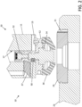
- An anti-rotation key 68 can also be provided in punch body 12, and configured to engage a corresponding slot on the inner surface of the punch guide or bushing to orient punch body 12 with respect to the punch press. Suitable keys 68 may also be provided in different locations on punch body 12 (e.g., above or below latch mechanism 50), or directly on punch tip 14.
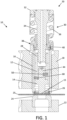
- the force required to perform a punch operation flows generally axially from (e.g., threaded) coupling 28 at the top of punch device 10, down through the punch driver (or punch body 12) to punch point 15 on working end 14W of punch tip 14.
- punch assembly 10 travels downward to punch a hole in the sheet material or workpiece, the workpiece pushes back upward against punch point 15, introducing a substantial compressive loading C between punch tip 14 and punch body 12.
- the punch loading can easily exceed several tons, depending on punch size, and the working material composition and thickness.
- compressive loading may be directed to the contact surfaces 49 defined between punch body 12 and punch tip 14, for example by maintaining clearance between stem 44 and the axial cavity in punch body 12, or other relevant coupling structures.
- the load may be directed to the interface between the top surface of the flange or ledge surfaces 49, extending circumferentially about stem 44 on punch tip 14, and complementary corresponding surfaces on the bottom surface of punch body 12, extending around the axial cavity in which stem 44 is engaged. Note that there may be some gaps along the load-bearing surfaces (e.g., due to the alignment features), but these are typically small in relation to the load-bearing surface area, in order to maintain the strength and integrity of punch device 10.
- An elastic member may also be configure to provide a bias between punch tip stem 44 and punch body 12, as described below, outside the compressive loading path.
- FIG. 8B illustrates an alternate configuration in which punch tip 14 is oriented with respect to the driver or punch body 12 via an orientation pin 64 pressed into the top surface of the punch tip 14, instead of the driver or punch body 12.
- precision alignment slot 65 is formed in the bottom of punch body 12, rather than punch tip 14.
- an axially engaged pin 64 may be provided in the bottom of punch body 12 for engagement with a corresponding slot or hole 65 in punch tip 14, as described above.
- FIG. 8C is a section view of punch apparatus 10, with an elastic bumper member 120 configured to generate bias and reduce or minimize relative motion (or "jiggle") of the punch tip insert (or punch insert) 14 with respect to the punch body (or punch driver) 12. Compression (C) and tensile (T) loadings are also illustrated, as experienced in the punching and stripping phases of press operation, respectively.
- pivot latch coupling mechanism 50 is provided with a laterally-oriented alignment pin 64 and slot 65 to provide precision angular alignment between punch tip 14 and punch body 12.
- the punch tip or insert 14 is oriented with respect to the punch driver or punch body 12 by engaging a slot 65 in the upper shank (or insert stem) 44 with a horizontal pin 64 inserted in the lateral or radial direction, from the outer side of the driver or punch body 12.
- latch mechanism 50 could also be formed with sufficient precision to provide the desired precision in angular orientation.
- Elastic bumper member 120 is provided as a rubber or plastic (polymer) member, which is positioned along punch axis A of punch assembly 10, and disposed between punch driver 12 and the upper surface of punch tip 14 (that is, within the axial cavity where the stem or tang of punch tip 14 is received in punch driver or body 12).
- One end of bumper 120 can be formed as an elongated elastic member inserted into an axial hole extending upward from the bottom cavity in punch body 12. The other end of bumper 120 contacts the upper surface of punch tip 14, in a compressive or resilient coupling or bias engagement to reduce relative motion.
- bumper member 120 can have any suitable configuration, including, but not limited to, an O-ring or resilient disk.
- Bumper member 120 can be formed of elastic materials such as plastic or rubberized polymer, or provided as a resilient (e.g., spring) bias element, which is positioned to dampen or reduce relative motion between punch driver or punch body 12 and removable punch tip or insert 14. Bumper member 120 is configured to provide sufficient resilient bias (e.g., outward bias) to reduce "jiggle," shaking, wiggling, and other motion of punch tip 14 with respect to punch body 12, e.g., due to vibration or during assembly of punch apparatus 10. At the same time, bumper member 120 can also be substantially isolated from the punch and stripping load paths C and T, as described above.
- resilient bias element e.g., outward bias
- Bumper 120 is formed a resilient member positioned between punch body 12 and the upper surface of punch tip 14, where the stem is received within the axial cavity in the bottom of the punch body (or punch driver) 12.
- bumper member 122 can be provided in a substantially compressive coupling or biasing relationship between punch body 12 and the upper surface of punch tip 14.
- punch body 12 and punch tip 14 can be provided with grooves, chamfers or other surface features configured to receive bumper member 120, and to help retain bumper member 120 in a suitable position between punch body 12 and punch tip (or punch tip insert) 14.
- FIG. 9A is a side view of punch assembly 10, showing an alternate precision alignment protrusion 110 on punch body 12, and a corresponding slot or cut-out 112 on punch tip 14.
- FIG. 9B is an isometric view of punch assembly 10 as shown in FIG. 9A .
- Complementary precision alignment features such as a machined protrusion 110 and cut-out 112 can be provided integral to or formed on the bottom end of punch body 12 and the top end of punch tip 14, respectively, e.g., parallel to punch axis A and at a maximal radial distance from the punch center.
- Complementary protrusion features 110 and cut-out features 112 can be milled flat or otherwise configured for engagement along an outer diameter or circumference of punch body 12 and punch tip 14, and adapted to allow precise angular orientation to be transferred between punch body 12 and punch tip 14, e.g., when precision cut-out 112 on punch tip 14 engages precision orientation protrusion 110 on punch body 12.
- alignment protrusion 110 and cut-out 112 can be reversed, and provided for precision alignment by similar engagement along the abutting surfaces of punch tip 14 and punch body 12, respectively.
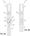
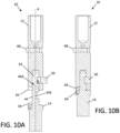
- FIG. 10A is a section view of punch assembly 10, in a disengaged position with latch 50 open to show an alternate alignment or precision orientation pin 64 and slot 65.
- FIG. 10B is an alternate section view of punch assembly 10, in an engaged position with latch 50 closed.
- Chamfer features (or a slanted cylindrical surface) on the top end 44A of punch tip stem 44 and/or the inner portion of pivot latch 50 can be configured to cam pivot latch 50 into the open position when stem 44 of punch tip 14 is pushed into axial cavity 54 in punch body 12, while torsion spring 57 resiliently urges pivot latch 50 toward the closed position.
- pivot latch 50 will rotate from the open position by force of torsion spring 57, into the closed position with the inner portion of latch 50 engaged in corresponding slot 44S in the punch insert or punch tip stem 44.
- Pivot latch 50 can further be constrained, by resilient or various means, as described in the examples below, in order to remain in either the locked or open position, and to ease operation of the latch mechanism.
- pivot latch 50 is rotated by the force of torsional spring 57 from an open or disengaged (unlocked) position into a closed or locked position inside latch pocket 55 in punch body 12. In the closed position, pivot latch 50 engages with the corresponding channel or groove 44S on punch stem (or insert stem) 44.
- FIGS. 11A and 11B are section and isometric views, respectively, of punch assembly 10 with punch body 12 suitable for use in a rail-type or single-tool punch press apparatus.
- Pivot latch 52 is shown in the closed position, with punch tip (or insert) 14 engaged within the axial cavity in punch body 12, and spring ejector 52 compressed against the top of punch tip 14.
- punch body 12 can be configured for single-tool or rail-type mounting, utilizing punch key 13 for alignment as described above with respect to FIG. 2 .
- FIGS. 11C and 11D are section and isometric views, respectively, of a rail-mount punch assembly 10 with punch tip 14 disengaged from punch body 12.
- Spring latch 50 is shown in the open or unlocked position, with punch tip 14 removed from axial cavity 54 in punch body 12 along punch axis A.
- slot 44S may be formed as a generally circular feature extending about the tang end or stem 44 of punch tip 14, as an alternative to the straight (or "D-shaped") channel embodiments described above.
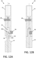
- FIG. 12A is a section view of an alternate punch assembly 10, with latch 50 disengaged to show the position of precision orientation pin 64 extending axially from the lower portion of punch body 12.
- FIG. 12B is an alternate section view of punch assembly 10, with latch 50 engaged. In this position, pin 64 fits into a complimentary slot or hole 65 formed in the top surface of punch tip 14, in order to provide precision angular alignment of punch tip 14 with respect to punch body 12 (see also, e.g., FIGS. 13C and 13D , below).
- FIGS. 13A and 13B are side and isometric views of a punch assembly 10 with a spiral groove feature 130.
- punch tip 14 is engaged within punch body 12, with latch 50 in a closed position.
- FIGS. 13C and 13D are corresponding views of the grooved punch assembly 10, with latch 50 in an open position and punch tip 14 disengaged.
- An axial alignment pin 64 extends downward from the bottom surface of punch body 12, and is configured to engage a corresponding slot or hole 65 in punch tip 14.
- spiral lubrication grooves 130 are formed on the outer diameter (OD) of punch body 12, providing more uniform fluid flow for reduced friction punch-to-guide operation.
- One or more longitudinal or vertical slots 132 can be formed in the outer diameter of punch tip 14, for air/oil flow during punching and stripping operations.
- a groove 130 may be formed around the punch tip or insert 14, in an optional geometry.
- Recess 60 can be provided to access the free end of latch 50, for manual operation between the closed and open positions.
- a torsion spring 57 or similar component can be provided to pull or pivot latch member 50 back into the closed position, with the outer surface of latch 50 in a conforming or recessed relationship within the OD of punch body 12, as described above.
- a spring element is not required, and it is possible for the punch guide to hold latch 50 in the closed position when punch tip 14 is inserted, after manually maneuvering latch open 50 and closed.
- a ball plunger, urethane member, or similar resilient bias element 45 can also be used to hold latch 50 in the open and/or closed position, e.g., in the closed position until punch assembly 10 is inserted into the punch guide.
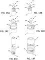
- FIGS. 14A and 14B are isometric views of a first representative punch tip 14, as described herein.
- FIGS. 14C and 14D are isometric views of a second representative punch tip 14.
- FIG. 14E is an isometric view of a representative punch body 12 for use in combination with punch tip 14 of FIGS. 14A and 14B
- FIG. 14E is a representative punch body 12 for use with punch tip 14 of FIGS. 14C and 14D .
- punch body 12 and punch tip 14 can readily be configured with various different sizes, OD's, and aspect ratios, for example as adapted for different "A" and "B" type stations on a turret press, or in a wide range of other punch tip applications.
- punch point 15 at the working end of punch tip 14 can also take on a variety of forms, such as round, oval, square, rectangular, triangular, oblong, arcuate, polyhedral, etc.
- punch tip (or insert) 14 typically extends from punch point 15 at the first end (or working end) of punch tip 14, to top 44A of stem 44, at the second (opposite) end of punch tip 14.
- One or more air/oil slots 132 can be provided along the outer diameter of punch tip 14, along with an alignment key slot or hole 65, for example a slanted or curved slot 65 extending to the outer diameter of punch tip 14 as shown.
- these elements are not required, and one or more of the air/oil slots 132 and alignment slots 65 may be absent, in some embodiments.
- a slot or channel 44S is provided in stem 44 to receive the inner portion of latch mechanism 50, when stem 44 is inserted into the punch body.
- channel 44S may be machined or formed in a middle portion of stem 44, oriented generally transvers to the punch tip axis along partial arc of stem 44, in order to engage or otherwise accommodate the inner portion of a similarly oriented latch member 50, when in the closed position.
- top end 44A of the shank or stem 44 can beveled, tapered or otherwise adapted to open latch 50 upon manual insertion into punch body 12, for example without requiring tools, with latch 50 engaging into slot 44S when stem 44 is fully inserted.
- Angular alignment can also be provided via suitable tolerance of slot 44S with respect to the inner surface of latch 50, as an alternative to using an alignment pin 64 to operate or facilitate rotation of the latch mechanism, and to engage with a corresponding hole or precision slot 65, as described above.
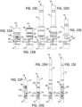
- FIGS. 15A, 15B, 15C, 15D, 15E, 15F, 15G, 15H and 15I are alternate examples of punch assembly 10.
- Punch assemblies 10 are variously adapted for use in turret press stations or rail-type punch press systems, as described herein.
- spiral lubrication grooves 130 may be variously configured on punch body 12 to provide more uniform fluid flow for reduced punch-to-guide friction, e.g., as shown in FIGS. 15A, 15D, 15F and 15I .
- Air/oil slots 132 may also be provided punch tip 14.
- the punch drivers or punch bodies 12 include connecting slots 133 that match up with slots 132 on punch tips 14, e.g., in a longitudinally aligned configuration, as shown in FIGS. 15B, 15D, 15G and 15I .
- these features are optional, and other air/oil mix flow paths from punch body 12 to punch tip 14 are encompassed.
- a punch system comprises: a punch body having a cavity therein; a punch tip comprising a punch tip stem and a working end opposite the punch tip stem along an axis of the punch tip, the punch tip stem being configured for selective engagement and disengagement within the cavity of the punch body; and a latch mechanism comprising a pivoting member configured for the selective engagement of the punch tip stem within the cavity in a closed position of the latch mechanism within the punch body, and further configured for the selective disengagement of the punch tip from the punch body in an open position of the latch mechanism extending from the punch body.
- the punch system may be configured wherein the free end of the pivoting member is configured to pivot at least partially outward of an outer circumference of the punch body in the open position, and into conforming relation within a pocket defined in the outer circumference of the punch body in the closed position.
- the punch system may be configured wherein the free end of the pivoting member is configured to be constrained within the pocket against motion from the closed position to the open position by an inner surface of a punch guide or bushing, when the punch body is disposed therein.
- the punch system may be configured wherein the punch tip stem is further configured to engage the latch mechanism in the closed position when the punch tip stem is fully inserted into the cavity.
- the punch system may be configured further comprising an ejector member disposed along an axis of the cavity, the ejector member configured to urge the punch tip out of axial engagement with the punch body when the pivot latch mechanism is manipulated from the closed position to the open position.
- the punch system may be configured further comprising a resilient outward biasing member configured for engagement between the punch body and punch tip stem when selectively engaged within the cavity.
- the punch system may be configured wherein the pivoting member is configured for precise angular orientation of the punch tip with respect to the punch body by precision engagement within a receiving feature integral to the punch tip stem.
- the punch system may be configured wherein the latch mechanism is configured to be resiliently held in one or both of the open position and the closed by a ball plunger, and/or urethane member or other resilient element; alternately by a rigid type of fastener.
Landscapes
- Engineering & Computer Science (AREA)
- Mechanical Engineering (AREA)
- Life Sciences & Earth Sciences (AREA)
- Forests & Forestry (AREA)
- Punching Or Piercing (AREA)
- Mounting, Exchange, And Manufacturing Of Dies (AREA)
- Adornments (AREA)
- Automatic Assembly (AREA)
- Perforating, Stamping-Out Or Severing By Means Other Than Cutting (AREA)
Claims (14)
- Stanzsystem (10), umfassend:einen Stanzkörper (12) der einen Hohlraum (54) darin aufweist;eine Stanzspitze (14), die einen Stanzspitzenstempel (44) und ein Arbeitsende gegenüber dem Stanzspitzenstempel (44) entlang einer Achse (A) der Stanzspitze (14) umfasst, wobei der Stanzspitzenstempel (44) dazu konfiguriert ist, innerhalb des Hohlraums (54) des Stanzkörpers (12) selektiv in Eingriff genommen und gelöst zu werden; undeinen Schließmechanismus (50), der ein Schwenkelement umfasst, das dazu konfiguriert ist, den Stanzspitzenstempel (44) innerhalb des Hohlraums (54) in einer geschlossenen Position des Schließmechanismus innerhalb des Stanzkörpers (12) selektiv in Eingriff zu nehmen, und ferner dazu konfiguriert ist, die Stanzspitze (14) in einer offen Position des Schließmechanismus (50), die sich von dem Stanzkörper (12) erstreckt, von dem Stanzkörper (12) zu lösen;wobei das Schwenkelement ein freies Ende und ein Scharnierende in Schwenkeingriff mit dem Stanzkörper (12) umfasst, wobei das freie Ende des Schwenkelements dazu konfiguriert ist, das Scharnierende zu schwenken, um einen inneren Abschnitt des freien Endes mit einem aufnehmenden Schlitz (44S), der in dem Stanzspitzenstempel (44) definiert ist, in Eingriff zu bringen, wenn sich der Schließmechanismus (50) in der geschlossenen Position befindet, und das freie Ende von dem aufnehmenden Schlitz (44S) zu lösen, wenn sich der Schließmechanismus (50) in der offenen Position befindet;wobei das Schwenkelement mit einem Federelement federbelastet ist und ein Scharnier an dem Scharnierende angeordnet und an dem Stanzkörper (12) angebracht ist, wobei das gegenüberliegende freie Ende dazu konfiguriert ist, quer zu der Achse (A) der Stanzspitze (14) um das Scharnierende zu schwenken, um die Stanzspitze (14) in Eingriff zu nehmen oder zu lösen.
- Stanzsystem nach Anspruch 1, wobei:das freie Ende des Schwenkelements dazu konfiguriert ist, in der offenen Position von einem äußeren Umfang des Stanzkörpers (12) mindestens teilweise nach außen und in der geschlossenen Position in Anpassungsbeziehung innerhalb einer Tasche (55), die in dem äußeren Umfang des Stanzkörpers (12) definiert ist, zu schwenken; oderdas freie Ende des Schwenkelements dazu konfiguriert ist, innerhalb einer Tasche (55), die in dem äußeren Umfang des Stanzkörpers (12) definiert ist, durch eine innere Fläche einer Stanzführung (16) oder eine Buchse daran gehindert zu werden, sich aus der geschlossenen Position in die offene Position zu bewegen, wenn der Stanzkörper (12) darin angeordnet ist.
- Stanzsystem nach Anspruch 1, wobei:der Stanzspitzenstempel (44) einen abgeschrägten Spitzenabschnitat umfasst, der dazu konfiguriert ist, den Schließmechanismus (50) durch manuelles Einfügen in den Hohlraum (54) des Stanzkörpers (12) aus der geschlossenen Position in die offene Position zu betätigen; oderder Stanzspitzenstempel (44) ferner dazu konfiguriert ist, den Schließmechanismus (50) in der geschlossenen Position in Eingriff zu nehmen, wenn der Stanzspitzenstempel (44) vollständig in den Hohlraum (54) eingefügt ist.
- Stanzsystem nach Anspruch 1, ferner umfassend ein Auswerfelement (52), das entlang einer Achse (A) des Hohlraums (54) angeordnet ist, wobei das Auswerfelement (52) dazu konfiguriert ist, die Stanzspitze (14) aus der axialen Ineingriffnahme mit dem Stanzkörper (12) zu drängen, wenn der Schwenkschließmechanismus (50) aus der geschlossenen Position in die offenen Position beeinflusst wird.
- Stanzsystem nach Anspruch 1, ferner umfassend ein nachgiebiges Vorspannelement nach außen, das dazu konfiguriert ist, zwischen dem Stanzkörper (12) und dem Stanzspitzenstempel (44) in Eingriff genommen zu werden, wenn es selektiv in Eingriff mit dem Hohlraum (54) steht.
- Stanzsystem nach Anspruch 1, ferner umfassend einen Präzisionsausrichtungsstift (64), der dazu konfiguriert ist, in dem Stanzkörper (12) oder der Stanzspitze (14) angeordnet zu sein, wobei der Präzisionsausrichtungsstift (64) ferner dazu konfiguriert ist, für eine präzise Winkelorientierung der Stanzspitze (14) hinsichtlich des Stanzkörpers (12) in ein entsprechendes Präzisionsausrichtungsloch oder einen entsprechenden Präzisionsausrichtungsschlitz (65), das/der in der Stanzspitze (14) oder dem Stanzkörper (12) definiert ist, in einer Längs- oder Querkonfiguration eingefügt zu werden
- Stanzsystem nach Anspruch 6, wobei ein einzelner Präzisionsausrichtungsstift (64) sowohl als Schließstift, der dazu konfiguriert ist, den Schließmechanismus (50) zu beeinflussen, als auch in doppelter Funktion als Orientierungsstift, der in das Präzisionsausrichtungsloch oder den Präzisionsausrichtungsschlitz (65) in einem oberen Flanschabschnitt der Stanzspitze (14) vorsteht, verwendet wird.
- Stanzsystem nach Anspruch 1, ferner komplementäre Präzisionsausrichtungsmerkmale umfassend, die einstückig mit dem Stanzkörper (12) und der Stanzspitze (14) sind, wobei die Präzisionsausrichtungsmerkmale zur präzisen Winkelorientierung konfiguriert sind, die zwischen dem Stanzkörper (12) und der Stanzspitze (14) zu übertragen ist, wenn sie entlang anliegender Flächen davon in Eingriff stehen.
- Stanzsystem nach Anspruch 1, wobei das Schwenkelement durch präzises Ineingriffnehmen innerhalb eines aufnehmenden Merkmals, das einstückig mit dem Stanzspitzenstempel (44) ist, zur präzisen Winkelorientierung der Stanzspitze (14) in Bezug auf den Stanzkörper (12) konfiguriert ist.
- Stanzsystem nach Anspruch 1, ferner umfassend ein Ausrichtungselement, das radial von der Stanzspitze (14) vorsteht, wobei das Ausrichtungselement dazu konfiguriert ist, eine Stanzführung (16) oder ein Gehäuse in Eingriff zu nehmen, um eine präzise Winkelorientierung der Stanzspitze (14) mit diesem bereitzustellen.
- Stanzsystem nach Anspruch 1, wobei der Schließmechanismus (50) dazu konfiguriert ist, durch einen Kugelstößel oder ein nachgiebiges Element (45) in lösbarem Eingriff in einer oder beiden der offenen Position und der geschlossenen Position gehalten zu werden.
- Stanzsystem nach Anspruch 1, ferner umfassend:das Arbeitsende der Stanzspitze, das dazu konfiguriert ist, durch eine Stanzpresse (20) betätigt zu werden;ein abgeschrägtes Spitzenelement, das dazu konfiguriert ist, den Schließmechanismus (50) zu betätigen, damit er um ein Scharnierende quer zu der Achse (A) der Stanzspitze (14) schwenkt, indem der Stanzspitzenstempel (44) in den axialen Hohlraum (54) entlang der Achse (A) der Stanzspitze (14) eingefügt wird, wobei der aufnehmende Schlitz (44S) dazu konfiguriert ist, den Schließmechanismus (50) in Eingriff zu nehmen, wenn der Stanzspitzenstempel (44) vollständig eingefügt ist; undeine Passfläche, die sich im Allgemeinen umlaufend um den Stanzspitzenstempel (44) der Stanzspitze (14) erstreckt, wobei die Passfläche dazu konfiguriert ist, während der Betätigung durch die Stanzpresse (20) eine Druckbelastung von dem Stanzkörper (12) auf das Arbeitsende zu übertragen, wobei der Stanzspitzenstempel (44) im Wesentlichen von der Druckbelastung isoliert ist.
- Stanzsystem nach Anspruch 12, wobei der aufnehmende Schlitz (44s) einen im Wesentlichen gradlinigen oder gekrümmten oder umlaufenden Kanal umfasst, der dazu konfiguriert ist, eine innere Fläche des Schließmechanismus (50) in Eingriff zu nehmen, um die Stanzspitze (14) unter Zugbelastung eines Abstreifvorgangs der Stanzpresse (20) innerhalb des Stanzkörpers (12) zu halten.
- Verfahren zum Verwenden des Stanzsystems nach Anspruch 12, umfassend Ineingriffbringen der Stanzspitze (14) mit dem Stanzkörper (12), wobei der Stanzspitzenstempel (44) in den axialen Hohlraum (54) eingefügt wird, um den Schließmechanismus (50) aus der geschlossenen Position in die offene Position zu betätigen und ferner den Schließmechanismus (50) in der geschlossenen Position in Eingriff zu nehmen, wenn der Stanzspitzenstempel (44) vollständig eingefügt ist.
Applications Claiming Priority (3)
| Application Number | Priority Date | Filing Date | Title |
|---|---|---|---|
| US201562113778P | 2015-02-09 | 2015-02-09 | |
| US14/985,863 US10646913B2 (en) | 2015-02-09 | 2015-12-31 | Punch assembly with replaceable punch tip |
| PCT/US2016/015940 WO2016130351A1 (en) | 2015-02-09 | 2016-02-01 | Punch assembly with replaceable punch tip |
Publications (3)
| Publication Number | Publication Date |
|---|---|
| EP3256271A1 EP3256271A1 (de) | 2017-12-20 |
| EP3256271C0 EP3256271C0 (de) | 2024-07-10 |
| EP3256271B1 true EP3256271B1 (de) | 2024-07-10 |
Family
ID=55646841
Family Applications (2)
| Application Number | Title | Priority Date | Filing Date |
|---|---|---|---|
| EP16705635.7A Active EP3256271B1 (de) | 2015-02-09 | 2016-02-01 | Stanzanordnung mit ersetzbarer stanzspitze |
| EP16713138.2A Active EP3256272B1 (de) | 2015-02-09 | 2016-02-09 | Stanzanordnung mit austauschbarer, durch einen kopplungsstift gesicherte stanzspitze |
Family Applications After (1)
| Application Number | Title | Priority Date | Filing Date |
|---|---|---|---|
| EP16713138.2A Active EP3256272B1 (de) | 2015-02-09 | 2016-02-09 | Stanzanordnung mit austauschbarer, durch einen kopplungsstift gesicherte stanzspitze |
Country Status (7)
| Country | Link |
|---|---|
| US (3) | US10646913B2 (de) |
| EP (2) | EP3256271B1 (de) |
| JP (2) | JP2018505061A (de) |
| CN (2) | CN107872990B (de) |
| CA (2) | CA2975287C (de) |
| MX (2) | MX390544B (de) |
| WO (2) | WO2016130351A1 (de) |
Families Citing this family (22)
| Publication number | Priority date | Publication date | Assignee | Title |
|---|---|---|---|---|
| US9321095B2 (en) * | 2010-06-30 | 2016-04-26 | General Electric Company | Apparatuses and methods for cutting porous substrates |
| US10646913B2 (en) | 2015-02-09 | 2020-05-12 | Mate Precision Tooling, Inc. | Punch assembly with replaceable punch tip |
| USD820328S1 (en) | 2015-12-31 | 2018-06-12 | Mate Precision Tooling, Inc. | Punch insert |
| USD822725S1 (en) | 2015-12-31 | 2018-07-10 | Mate Precision Tooling, Inc. | Punch insert |
| US10596614B2 (en) * | 2016-05-05 | 2020-03-24 | Swanstrom Tools Usa Inc. | Punch and die holding apparatus and method |
| US10792725B2 (en) * | 2017-06-13 | 2020-10-06 | Stolle Machinery Company, Llc | Ram assembly with removable punch mounting assembly |
| CN212793322U (zh) | 2017-08-04 | 2021-03-26 | 米沃奇电动工具公司 | 手持式冲压工具 |
| CN108858441A (zh) * | 2018-06-27 | 2018-11-23 | 和县新拓工业设计有限公司 | 一种工业打孔机用碎屑收集装置 |
| DE102018120500A1 (de) * | 2018-08-22 | 2020-02-27 | Tox Pressotechnik Gmbh & Co. Kg | Adapterelement für eine Anbringung eines Matrizenhalters an eine Werkzeugzange |
| CN109201871B (zh) * | 2018-11-28 | 2025-01-24 | 重庆长江电工工业集团有限公司 | 一种弹壳冲孔装置 |
| JP6727357B1 (ja) * | 2019-02-12 | 2020-07-22 | 株式会社アマダ | パンチハイト測定装置 |
| US12103064B2 (en) | 2019-04-08 | 2024-10-01 | E&S Enterprises Inc. | Punch assembly with interchangeable tips |
| US11235370B2 (en) | 2019-04-08 | 2022-02-01 | E&S Enterprises Inc. | Punch assembly with interchangeable tips |
| DE102019215750A1 (de) * | 2019-10-14 | 2021-04-15 | Otto Bihler Maschinenfabrik Gmbh & Co. Kg | Einstellbare Koppel für Werkzeuge der Stanz- und Umformtechnik |
| JP7373798B2 (ja) * | 2020-02-04 | 2023-11-06 | パナソニックIpマネジメント株式会社 | 打抜き装置の調整装置および打抜き装置の調整方法 |
| JP7462173B2 (ja) * | 2020-04-20 | 2024-04-05 | パナソニックIpマネジメント株式会社 | 打ち抜き装置 |
| CN111438275B (zh) * | 2020-04-26 | 2021-11-09 | 昆山圣丰电子科技有限公司 | 一种冲头可调式模具及其加工方法 |
| US12138506B2 (en) * | 2020-10-23 | 2024-11-12 | Blindside Group Pty Ltd | Fitness equipment |
| US12246369B2 (en) * | 2021-05-13 | 2025-03-11 | Accurpress America Inc. | Press brake safety latch |
| CN115138765B (zh) * | 2022-07-26 | 2024-11-26 | 深圳市常丰激光刀模有限公司 | 一种激光循环冲压模具 |
| GB2614362B (en) * | 2022-08-10 | 2024-09-18 | I Holland Ltd | A tablet punch |
| US12623327B2 (en) * | 2023-02-16 | 2026-05-12 | Jimmie Gatlin | Advanced strut marker device for precise marking on manufactured struts |
Family Cites Families (168)
| Publication number | Priority date | Publication date | Assignee | Title |
|---|---|---|---|---|
| US199715A (en) | 1878-01-29 | Improvement in punches for metal | ||
| US1806694A (en) | 1931-05-26 | Locking mechanism | ||
| US1377292A (en) | 1921-05-10 | thomas | ||
| US1179476A (en) | 1914-06-29 | 1916-04-18 | George Paul Thomas | Metal-punching machinery. |
| US1386259A (en) | 1919-12-27 | 1921-08-02 | Jourdan Louis | Nut-fastener |
| US1383414A (en) | 1920-08-07 | 1921-07-05 | Mansell Walter Henry | Nut-lock and the like |
| US1569136A (en) | 1925-03-27 | 1926-01-12 | Anthracite Separator Co | Tool holder |
| US1784911A (en) | 1927-05-06 | 1930-12-16 | Jr Michael J Schlitters | Tool-retaining device |
| US1726012A (en) | 1927-06-25 | 1929-08-27 | Bilz William Fredrick | Nail driver |
| US1910275A (en) * | 1929-07-12 | 1933-05-23 | Whitman & Barnes Inc | Tool retainer |
| US2107581A (en) | 1932-10-31 | 1938-02-08 | John H Parsons | Tool retainer |
| US1979059A (en) * | 1933-01-30 | 1934-10-30 | Wallman Carl Birger | Punch retainer |
| US2245676A (en) | 1940-06-11 | 1941-06-17 | Emil M Johnson | Tool attachment |
| US2380343A (en) * | 1944-03-06 | 1945-07-10 | Domnic V Stellin | Interchangeable punch and die and retainer for same |
| US2448817A (en) | 1944-11-11 | 1948-09-07 | Reconstruction Finance Corp | Fastening device |
| US2431566A (en) | 1945-05-23 | 1947-11-25 | John F Kopczynski | Die |
| US2420146A (en) * | 1945-09-21 | 1947-05-06 | Mueller Otto | Locking and ejecting device |
| US2614781A (en) | 1949-06-16 | 1952-10-21 | William A Engel | Aircraft seat leg release means |
| US2522440A (en) | 1949-09-22 | 1950-09-12 | Roy J Freter | Cold punching metal parts |
| US2805866A (en) | 1954-12-22 | 1957-09-10 | Arthur L Amend | Tool-locking device |
| US2801859A (en) | 1956-01-12 | 1957-08-06 | John F Kopczynski | Machine tools |
| US2893291A (en) | 1956-07-20 | 1959-07-07 | Morey Machinery Co Inc | Draw toggles for spindle male tapers of milling and the like machines |
| US2927432A (en) | 1958-03-18 | 1960-03-08 | Ibm | Hydraulic positioning device |
| US2974967A (en) | 1959-01-23 | 1961-03-14 | Robert H King | Tool holding means |
| US2955831A (en) | 1959-01-27 | 1960-10-11 | Paul I Zandberg | Bur chuck |
| US3137193A (en) * | 1960-11-04 | 1964-06-16 | Lawrence V Whistler | Punch and die mounting device |
| US3190160A (en) | 1963-04-03 | 1965-06-22 | American Drill Bushing Company | Slug shedder |
| US3289519A (en) | 1964-12-14 | 1966-12-06 | Donato L Piccone | Latch mechanism for die block of punch press |
| US3495493A (en) | 1966-04-29 | 1970-02-17 | Trumpf & Co | Cutting or stamping machine having exchangeable stamping or cutting tool |
| US3447455A (en) | 1967-09-20 | 1969-06-03 | Honeywell Inc | Print-hammer mount and fabrication method |
| US3530750A (en) | 1968-01-05 | 1970-09-29 | Houdaille Industries Inc | Punching tool assembly |
| US3548700A (en) | 1968-03-21 | 1970-12-22 | Houdaille Industries Inc | Punch holder and drive assembly |
| DE1777363C3 (de) | 1968-07-03 | 1974-03-21 | Muhr Und Bender, 5952 Attendorn | Schnellwechselfutter, insbesondere für Stanzstempel. Ausscheidung aus: 1752689 |
| JPS476475Y1 (de) | 1969-04-03 | 1972-03-07 | ||
| US3641860A (en) | 1969-11-14 | 1972-02-15 | Lawrence V Whistler Sr | Punch retainer assembly |
| US3640170A (en) | 1969-12-05 | 1972-02-08 | Arthur D Bennett | Retainer for punch and die sets |
| US3600999A (en) | 1970-02-16 | 1971-08-24 | Houdaille Industries Inc | Punching tool assembly |
| JPS476475U (de) | 1971-02-16 | 1972-09-21 | ||
| US3735993A (en) | 1971-04-26 | 1973-05-29 | W F Seibert | Self-release and reload tooling device |
| US3904816A (en) | 1971-07-28 | 1975-09-09 | Hell Rudolf | Method for the dot-by-dot and line-by-line reproduction of picture originals |
| DE2201049C3 (de) | 1972-01-11 | 1978-04-06 | Winfried 4794 Schloss Neuhaus Schneider | Mosaikdruckkopf |
| US3763730A (en) | 1972-01-27 | 1973-10-09 | O Ahlegian | Optical hole film punch |
| US3759130A (en) | 1972-04-13 | 1973-09-18 | Mate Punch And Die Co | Replaceable tip shear proof punch |
| FR2221271B1 (de) | 1973-01-04 | 1976-05-14 | Beauplat Philippe | |
| JPS555877B2 (de) | 1973-08-15 | 1980-02-12 | ||
| US4092888A (en) | 1977-07-01 | 1978-06-06 | Wilson Tool Company | Self-stripping punch and guide assembly |
| JPS5555877Y2 (de) | 1977-10-04 | 1980-12-24 | ||
| US4146239A (en) | 1977-12-14 | 1979-03-27 | The Warner & Swasey Company | Tool holder lock assembly |
| US4174648A (en) | 1978-02-01 | 1979-11-20 | Wallis Bernard J | Punch retainer |
| JPS555877A (en) | 1978-06-30 | 1980-01-17 | Eidai Kogyo Kk | Device for splintering agalmatolite or like by disc saw |
| US4273015A (en) | 1979-06-04 | 1981-06-16 | Johnson Donald R | Dome head punch |
| US4375774A (en) | 1979-12-26 | 1983-03-08 | Wilson Tool Company | Adjustable punch head |
| JPS56113039U (de) | 1980-01-31 | 1981-09-01 | ||
| JPS5945330B2 (ja) | 1981-05-16 | 1984-11-06 | 旭化成株式会社 | イワシの収容方法 |
| JPS57189625U (de) | 1981-05-26 | 1982-12-01 | ||
| JPS5823221U (ja) | 1981-07-31 | 1983-02-14 | 株式会社 アマダ | パンチ組立体 |
| US4446767A (en) | 1981-11-30 | 1984-05-08 | Wilson Tool Company | Locking ring stripper plate assembly |
| US4503741A (en) | 1982-07-26 | 1985-03-12 | The Warner & Swasey Company | Bridge type punch press |
| JPS5989626U (ja) | 1982-12-10 | 1984-06-18 | カルソニックカンセイ株式会社 | プレス金型用ポンチの出し入れ装置 |
| US4487566A (en) | 1983-07-11 | 1984-12-11 | Barna Alex J | Punching tool having interchangeable punches |
| US4526077A (en) | 1983-07-21 | 1985-07-02 | Detroit Punch & Retainer Corporation | Heavy duty punch |
| US4661888A (en) | 1984-07-03 | 1987-04-28 | Hewlett-Packard Company | Removable modular housing for RF circuits |
| JPS6122698U (ja) | 1984-07-16 | 1986-02-10 | 有限会社丸中製作所 | 金型用刻印ホルダ− |
| FR2580988B1 (fr) | 1985-04-30 | 1988-11-18 | Esswein Sa | Outil de presse a parties travaillantes interchangeables |
| JPS62109819A (ja) | 1985-11-06 | 1987-05-21 | Mitsubishi Chem Ind Ltd | 有機半導体 |
| JPS62109819U (de) | 1985-12-25 | 1987-07-13 | ||
| US4762043A (en) | 1987-03-23 | 1988-08-09 | Jacob L. Reich | Long wearing punch |
| GB8708076D0 (en) | 1987-04-03 | 1987-05-07 | British Aerospace | Nose piece adaptors |
| JPH0644492Y2 (ja) | 1987-09-25 | 1994-11-16 | 力夫 西田 | 穿孔用工具 |
| US4862782A (en) | 1988-05-02 | 1989-09-05 | Ernst Robert E | Turret punch press tool assembly |
| US5020407A (en) | 1988-05-17 | 1991-06-04 | Brinlee Charles P | Adjustable form tool head |
| DE3818001C3 (de) | 1988-05-27 | 1998-02-12 | Trumpf Gmbh & Co | Stanzmaschine mit ein- und auswechselbarem Stanzwerkzeug und mit einem Werkstückvorschub |
| US4989484A (en) | 1988-08-19 | 1991-02-05 | Mate Punch & Die Company | Punch and stripper assembly |
| FR2641486A1 (fr) | 1989-01-06 | 1990-07-13 | Weber Ernest | Outil universel de poinconnage |
| US5044244A (en) | 1990-06-29 | 1991-09-03 | Olson Charles W | Heavy duty punch |
| US5271303A (en) | 1990-07-26 | 1993-12-21 | Strippit, Inc. | Stripper plate retaining ring |
| US5146832A (en) | 1991-05-24 | 1992-09-15 | Wilson Tool International, Inc. | Connector for rigidly connecting punch tip to punch pad |
| US5131303A (en) | 1991-08-12 | 1992-07-21 | Wilson Tool International | Punch assembly |
| JPH05192717A (ja) | 1992-01-20 | 1993-08-03 | Amada Co Ltd | 金型ストリップミス防止方法 |
| CN1032050C (zh) | 1992-06-30 | 1996-06-19 | 丁志强 | 往复式人力驱动机构 |
| US5329835A (en) | 1992-10-07 | 1994-07-19 | Wilson Tool International, Inc. | Adjustable length punch set assembly |
| US5301580A (en) | 1992-10-07 | 1994-04-12 | Wilson Tool International, Inc. | Locking ring stripper plate assembly |
| US5317894A (en) | 1993-03-12 | 1994-06-07 | Rockford Products Corporation | Quick change insert system |
| CA2098235A1 (en) | 1993-06-11 | 1994-12-12 | Salomon M. Fargeon | Tooling for turret punch press |
| JPH07164070A (ja) | 1993-12-16 | 1995-06-27 | Murata Mach Ltd | パンチプレス |
| DE19508091C1 (de) | 1995-03-08 | 1996-04-18 | Mate Punch And Die Gmbh | Stanzstempeleinheit |
| US5832798A (en) | 1994-08-10 | 1998-11-10 | Mate Precision Tooling Inc. | Punch unit |
| DE19505754C1 (de) | 1995-02-20 | 1996-05-02 | Mate Punch And Die Gmbh | Stanzstempeleinheit |
| US5752424A (en) * | 1995-06-06 | 1998-05-19 | Wilson Tool International, Inc. | Releasable tool piece punch assembly |
| EP0765718B1 (de) | 1995-09-26 | 2002-01-23 | Max Co., Ltd. | Rotationslochvorrichtung |
| FR2739255B1 (fr) | 1995-09-29 | 1998-09-04 | Rhone Merieux | Composition antiparasitaire pour le traitement et la protection des animaux de compagnie |
| DE19546969A1 (de) | 1995-12-15 | 1997-06-19 | Amada Gmbh | Schnellspannvorrichtung für zumindest ein Werkzeug einer Bearbeitungsmaschine |
| US5839341A (en) | 1996-04-12 | 1998-11-24 | Mate Precision Tooling | Punch unit |
| JP3222065B2 (ja) | 1996-07-03 | 2001-10-22 | 株式会社アマダ | パンチ組立体及び板押え |
| US5746104A (en) | 1996-08-23 | 1998-05-05 | Wilmington Rubber & Gasket Co., Inc. | Two-piece hole punch |
| JP3037168U (ja) | 1996-10-24 | 1997-05-06 | ゼブラ株式会社 | インク逆流防止機構を備えたボールペン |
| US5884546A (en) | 1997-02-21 | 1999-03-23 | Mate Precision Tooling Inc. | Punch unit |
| JPH10244331A (ja) | 1997-02-25 | 1998-09-14 | Mate Precision Tooling Inc | パンチユニット |
| JPH10244327A (ja) | 1997-02-28 | 1998-09-14 | Mate Precision Tooling Inc | パンチユニット |
| US5934165A (en) | 1997-03-19 | 1999-08-10 | Strippit, Inc. | Adjustable punch assembly |
| JP3193329B2 (ja) | 1997-10-06 | 2001-07-30 | 株式会社アマダ | パンチング金型 |
| US5884544A (en) | 1997-11-18 | 1999-03-23 | Emerson Electric Co. | Scroll saw vacuum attachment assembly |
| JP3208104B2 (ja) | 1997-11-20 | 2001-09-10 | 株式会社アマダ | 上金型装置及び金型ホルダ並びに金型ユニット |
| US6082516A (en) | 1998-01-22 | 2000-07-04 | Amada Engineering & Service Co., Inc. | Variable height adjustable punch assembly having quick release stripper plate |
| US6047621A (en) | 1998-02-27 | 2000-04-11 | Elba Electronetics, Inc. | Quick change adjustable punch tool assembly and method of adjustment |
| JP3452491B2 (ja) | 1998-08-04 | 2003-09-29 | 株式会社アマダ | パンチホルダ装置 |
| US6196103B1 (en) * | 1998-08-17 | 2001-03-06 | Mate Precision Tooling Inc. | Punch guide assembly |
| JP2000317551A (ja) | 1999-05-07 | 2000-11-21 | Hidaka Seiki Kk | 金 型 |
| US6311597B1 (en) | 1999-05-24 | 2001-11-06 | Humdinger, Inc. | Self-guiding punch and die set |
| JP4598213B2 (ja) | 1999-11-05 | 2010-12-15 | 株式会社アマダ | パンチ金型 |
| US6276247B1 (en) | 2000-03-03 | 2001-08-21 | Strippit, Inc. | Adjustable punch assembly with releasable locking |
| JP2002011531A (ja) | 2000-06-30 | 2002-01-15 | Amada Co Ltd | パンチ金型 |
| JP4349762B2 (ja) | 2000-10-26 | 2009-10-21 | 株式会社アマダ | 上型装置 |
| US7900543B2 (en) | 2000-11-06 | 2011-03-08 | Amada Company, Limited | Punch press, method of replacing punch and die for punch press, and punch system |
| JP4663895B2 (ja) | 2001-03-29 | 2011-04-06 | 株式会社アマダ | 金型装置 |
| US6755110B2 (en) | 2001-06-19 | 2004-06-29 | Wilson Tool International, Inc. | Adjustable length punch assembly |
| US6782787B2 (en) | 2001-08-02 | 2004-08-31 | Wilson Tool International, Inc. | Adjustable punch having externally accessible rotation release latch |
| US6725756B2 (en) | 2001-10-23 | 2004-04-27 | L.H. Carbide Corporation | Two-piece metal punch construction |
| BE1014961A3 (nl) | 2001-11-21 | 2004-07-06 | Delmoitie Christian | Ponsgereedschap. |
| US6755103B2 (en) | 2002-02-08 | 2004-06-29 | Wilson Tool International, Inc. | Ball-lock insert assemblies |
| US6895849B2 (en) | 2002-06-07 | 2005-05-24 | Wilson Tool International, Inc. | Stripper plate retention system |
| AT411819B (de) | 2002-09-16 | 2004-06-25 | Trumpf Maschinen Austria Gmbh | Biegewerkzeug und werkzeugaufnahmevorrichtung für ein solches |
| US6895797B2 (en) | 2002-10-23 | 2005-05-24 | Mate Precision Tooling Inc | Punch assembly with feed gap maximization |
| DE10261748B4 (de) | 2002-12-30 | 2011-07-28 | Mate Precision Tooling GmbH, 61440 | Stanzwerkzeug |
| US20040200333A1 (en) | 2003-04-14 | 2004-10-14 | Seeley David E. | 360 Degree ball lock groove for a tool assembly |
| US7661288B2 (en) | 2003-07-01 | 2010-02-16 | Wilson Tool International Inc. | Press brake tool safety key assemblies |
| US7069765B2 (en) | 2003-11-14 | 2006-07-04 | Manchester Tool & Die, Inc. | Release mechanism for end forming machine |
| JP4619049B2 (ja) | 2004-06-25 | 2011-01-26 | 株式会社アマダ | パンチ金型 |
| US7698979B2 (en) | 2004-09-22 | 2010-04-20 | Amada Tool America, Inc. | Biasing assembly for a punching device |
| JP2006110605A (ja) | 2004-10-15 | 2006-04-27 | Konitsuku:Kk | パンチプレス用上金型 |
| USD526667S1 (en) | 2004-11-17 | 2006-08-15 | Seikoh Giken Co., Ltd. | Sprue cutting punch for a disc-molding die |
| JP2006142337A (ja) | 2004-11-19 | 2006-06-08 | Amada Co Ltd | パンチ金型 |
| WO2006054694A1 (ja) | 2004-11-19 | 2006-05-26 | Amada Company, Limited | パンチ金型 |
| JP4609811B2 (ja) | 2004-11-29 | 2011-01-12 | 株式会社アマダ | パンチ組立体 |
| JP2006297466A (ja) | 2005-04-22 | 2006-11-02 | Amada Co Ltd | パンチ金型 |
| US7802506B2 (en) | 2005-07-04 | 2010-09-28 | Amada Company, Limited | Upper tool device and punch therefor |
| US7159426B1 (en) | 2005-09-27 | 2007-01-09 | Gm Global Technology Operations, Inc. | Quick change assembly for hydroforming punches |
| US7658134B2 (en) | 2005-09-29 | 2010-02-09 | Mate Precision Tooling, Inc. | Punch with self-contained punch recess adjustment indexing |
| JP2007136463A (ja) | 2005-11-15 | 2007-06-07 | Komatsu Sanki Kk | プレスブレーキ用金型およびその製造方法 |
| DE102006005572B4 (de) | 2005-12-05 | 2010-06-17 | Dietz Maschinen- Und Werkzeugbau Gmbh | Stanzvorrichtung |
| JP4913400B2 (ja) | 2005-12-16 | 2012-04-11 | 株式会社アマダ | パンチ金型 |
| SI1859876T1 (sl) | 2006-05-24 | 2009-08-31 | Ernesto Malvestiti S P A | Naprava za centriranje rezilne matrice |
| JP2008183576A (ja) | 2007-01-29 | 2008-08-14 | Konitsuku:Kk | パンチング金型 |
| CN201127968Y (zh) | 2007-08-17 | 2008-10-08 | 培祐股份有限公司 | 方便调整的冲孔模具 |
| USD629025S1 (en) | 2008-03-27 | 2010-12-14 | Greenleaf Richard J | Shedder pin |
| US7954404B2 (en) | 2008-04-29 | 2011-06-07 | Mate Precision Tooling, Inc. | Punch device with adjustment subassembly as retrofit insert or as original equipment |
| US20100107823A1 (en) * | 2008-09-10 | 2010-05-06 | Ming-Chieh Wu | Hose Clamp Pliers |
| US8408111B2 (en) | 2008-11-06 | 2013-04-02 | Wilson Tool International Inc. | Adjustable punch assemblies and associated adjustment methods |
| US8327745B2 (en) | 2008-11-06 | 2012-12-11 | Wilson Tool International Inc. | Punch assemblies and methods for modifying |
| US20100180744A1 (en) | 2009-01-20 | 2010-07-22 | Nordlin William F | Quick clamping assembly for driving a knockout punch |
| JP5555877B2 (ja) | 2011-02-14 | 2014-07-23 | 株式会社ソフイア | 遊技機 |
| KR20130011462A (ko) * | 2011-07-21 | 2013-01-30 | 삼성에스디아이 주식회사 | 태양 전지 모듈 및 그 제조 방법 |
| US8707841B2 (en) | 2011-11-11 | 2014-04-29 | Wilson Tool International Inc. | Punch assemblies and universal punch therefor |
| US9409223B2 (en) | 2011-11-11 | 2016-08-09 | Wilson Tool International Inc. | Punch assemblies and universal punch therefor |
| US10265756B2 (en) | 2012-02-06 | 2019-04-23 | Mate Precision Tooling, Inc. | Punch assembly with steel punch point insert removably secured therein |
| AT511591B1 (de) | 2012-02-07 | 2013-01-15 | Trumpf Maschinen Austria Gmbh | Biegewerkzeug mit sicherheitseinrichtung |
| US8997617B2 (en) | 2012-03-14 | 2015-04-07 | Mate Precision Tooling, Inc. | Punch assembly with quick attach punch point and stripper plate removably secure thereon |
| USD690333S1 (en) | 2012-05-11 | 2013-09-24 | Wilson Tool International Inc. | Punch tool |
| USD694788S1 (en) | 2012-09-27 | 2013-12-03 | National Machinery Llc | Punch for a progressive former |
| JP6071642B2 (ja) | 2013-02-28 | 2017-02-01 | 株式会社アマダホールディングス | パンチ金型 |
| USD742441S1 (en) | 2013-05-21 | 2015-11-03 | Wilson Tool International Inc. | Punch holder |
| USD719590S1 (en) | 2013-05-21 | 2014-12-16 | Wilson Tool International Inc. | Punch |
| CN203437498U (zh) | 2013-08-26 | 2014-02-19 | 天津海鸥表业集团有限公司 | 一种可调式模具 |
| US9555456B2 (en) | 2014-04-26 | 2017-01-31 | Wilson Tool International Inc. | Dynamic clamp and tool holders therefor |
| USD744554S1 (en) | 2014-08-01 | 2015-12-01 | Wilson Tool International Inc. | Tool |
| USD755863S1 (en) | 2014-08-01 | 2016-05-10 | Wilson Tool International Inc. | Tool |
| JP6454923B2 (ja) | 2014-11-21 | 2019-01-23 | 和歌山県 | 食品検査装置 |
| US10646913B2 (en) | 2015-02-09 | 2020-05-12 | Mate Precision Tooling, Inc. | Punch assembly with replaceable punch tip |
-
2015
- 2015-12-31 US US14/985,863 patent/US10646913B2/en active Active
-
2016
- 2016-02-01 MX MX2017010155A patent/MX390544B/es unknown
- 2016-02-01 EP EP16705635.7A patent/EP3256271B1/de active Active
- 2016-02-01 CA CA2975287A patent/CA2975287C/en active Active
- 2016-02-01 JP JP2017559774A patent/JP2018505061A/ja not_active Withdrawn
- 2016-02-01 CN CN201680020843.5A patent/CN107872990B/zh active Active
- 2016-02-01 WO PCT/US2016/015940 patent/WO2016130351A1/en not_active Ceased
- 2016-02-09 CA CA2975303A patent/CA2975303A1/en not_active Abandoned
- 2016-02-09 JP JP2017560469A patent/JP2018505062A/ja active Pending
- 2016-02-09 EP EP16713138.2A patent/EP3256272B1/de active Active
- 2016-02-09 MX MX2017010154A patent/MX2017010154A/es unknown
- 2016-02-09 US US15/019,572 patent/US10328479B2/en active Active
- 2016-02-09 CN CN201680020757.4A patent/CN107771107A/zh active Pending
- 2016-02-09 WO PCT/US2016/017129 patent/WO2016130530A1/en not_active Ceased
-
2018
- 2018-01-26 US US15/881,660 patent/US10751781B2/en active Active
Also Published As
| Publication number | Publication date |
|---|---|
| WO2016130351A1 (en) | 2016-08-18 |
| CN107872990B (zh) | 2021-01-15 |
| CA2975303A1 (en) | 2016-08-18 |
| EP3256271C0 (de) | 2024-07-10 |
| US20160229078A1 (en) | 2016-08-11 |
| CN107872990A (zh) | 2018-04-03 |
| US20160228936A1 (en) | 2016-08-11 |
| MX2017010155A (es) | 2018-08-01 |
| CA2975287A1 (en) | 2016-08-18 |
| EP3256271A1 (de) | 2017-12-20 |
| US20180147617A1 (en) | 2018-05-31 |
| CA2975287C (en) | 2023-08-08 |
| JP2018505062A (ja) | 2018-02-22 |
| US10328479B2 (en) | 2019-06-25 |
| EP3256272A1 (de) | 2017-12-20 |
| MX2017010154A (es) | 2018-04-24 |
| US10751781B2 (en) | 2020-08-25 |
| WO2016130530A1 (en) | 2016-08-18 |
| JP2018505061A (ja) | 2018-02-22 |
| CN107771107A (zh) | 2018-03-06 |
| MX390544B (es) | 2025-03-20 |
| US10646913B2 (en) | 2020-05-12 |
| EP3256272B1 (de) | 2018-11-21 |
Similar Documents
| Publication | Publication Date | Title |
|---|---|---|
| US10751781B2 (en) | Punch assembly with replaceable punch tip | |
| EP1799410B1 (de) | Vorspannanordnung für eine stanzvorrichtung | |
| US9687994B2 (en) | Punch assemblies and methods for modifying | |
| EP2812164B1 (de) | Stanzwerkzeug mit lösbar darin gesichertem stahlstanzpunkteinsatz | |
| EP3002069B1 (de) | Einstellbare stanzanordnungen und zugehörige einstellverfahren | |
| EP1399279B1 (de) | Längenverstellbares stanzwerkzeug | |
| CN105102145B (zh) | 冲压设备 | |
| AU2002256179A1 (en) | Adjustable length punch assembly | |
| US12350729B2 (en) | Stamping dies and guided retainer devices for use in same | |
| EP3450044A1 (de) | Verstellbare stanz kopfmontage | |
| US20100011932A1 (en) | Cutting punch holder | |
| HK1117095A (zh) | 用於冲孔装置的偏压组件 |
Legal Events
| Date | Code | Title | Description |
|---|---|---|---|
| STAA | Information on the status of an ep patent application or granted ep patent |
Free format text: STATUS: THE INTERNATIONAL PUBLICATION HAS BEEN MADE |
|
| PUAI | Public reference made under article 153(3) epc to a published international application that has entered the european phase |
Free format text: ORIGINAL CODE: 0009012 |
|
| STAA | Information on the status of an ep patent application or granted ep patent |
Free format text: STATUS: REQUEST FOR EXAMINATION WAS MADE |
|
| 17P | Request for examination filed |
Effective date: 20170802 |
|
| AK | Designated contracting states |
Kind code of ref document: A1 Designated state(s): AL AT BE BG CH CY CZ DE DK EE ES FI FR GB GR HR HU IE IS IT LI LT LU LV MC MK MT NL NO PL PT RO RS SE SI SK SM TR |
|
| AX | Request for extension of the european patent |
Extension state: BA ME |
|
| DAV | Request for validation of the european patent (deleted) | ||
| DAX | Request for extension of the european patent (deleted) | ||
| STAA | Information on the status of an ep patent application or granted ep patent |
Free format text: STATUS: EXAMINATION IS IN PROGRESS |
|
| 17Q | First examination report despatched |
Effective date: 20210506 |
|
| RAP1 | Party data changed (applicant data changed or rights of an application transferred) |
Owner name: MATE PRECISION TECHNOLOGIES INC. |
|
| P01 | Opt-out of the competence of the unified patent court (upc) registered |
Effective date: 20230818 |
|
| GRAP | Despatch of communication of intention to grant a patent |
Free format text: ORIGINAL CODE: EPIDOSNIGR1 |
|
| STAA | Information on the status of an ep patent application or granted ep patent |
Free format text: STATUS: GRANT OF PATENT IS INTENDED |
|
| INTG | Intention to grant announced |
Effective date: 20240212 |
|
| GRAS | Grant fee paid |
Free format text: ORIGINAL CODE: EPIDOSNIGR3 |
|
| GRAA | (expected) grant |
Free format text: ORIGINAL CODE: 0009210 |
|
| STAA | Information on the status of an ep patent application or granted ep patent |
Free format text: STATUS: THE PATENT HAS BEEN GRANTED |
|
| AK | Designated contracting states |
Kind code of ref document: B1 Designated state(s): AL AT BE BG CH CY CZ DE DK EE ES FI FR GB GR HR HU IE IS IT LI LT LU LV MC MK MT NL NO PL PT RO RS SE SI SK SM TR |
|
| REG | Reference to a national code |
Ref country code: CH Ref legal event code: EP |
|
| REG | Reference to a national code |
Ref country code: DE Ref legal event code: R096 Ref document number: 602016088324 Country of ref document: DE |
|
| U01 | Request for unitary effect filed |
Effective date: 20240710 |
|
| P04 | Withdrawal of opt-out of the competence of the unified patent court (upc) registered |
Free format text: CASE NUMBER: APP_48688/2024 Effective date: 20240826 |
|
| U07 | Unitary effect registered |
Designated state(s): AT BE BG DE DK EE FI FR IT LT LU LV MT NL PT RO SE SI Effective date: 20240902 |
|
| P05 | Withdrawal of opt-out of the competence of the unified patent court (upc) changed |
Free format text: CASE NUMBER: APP_48688/2024 Effective date: 20240902 |
|
| PG25 | Lapsed in a contracting state [announced via postgrant information from national office to epo] |
Ref country code: NO Free format text: LAPSE BECAUSE OF FAILURE TO SUBMIT A TRANSLATION OF THE DESCRIPTION OR TO PAY THE FEE WITHIN THE PRESCRIBED TIME-LIMIT Effective date: 20241010 |
|
| PG25 | Lapsed in a contracting state [announced via postgrant information from national office to epo] |
Ref country code: GR Free format text: LAPSE BECAUSE OF FAILURE TO SUBMIT A TRANSLATION OF THE DESCRIPTION OR TO PAY THE FEE WITHIN THE PRESCRIBED TIME-LIMIT Effective date: 20241011 Ref country code: PL Free format text: LAPSE BECAUSE OF FAILURE TO SUBMIT A TRANSLATION OF THE DESCRIPTION OR TO PAY THE FEE WITHIN THE PRESCRIBED TIME-LIMIT Effective date: 20240710 |
|
| PG25 | Lapsed in a contracting state [announced via postgrant information from national office to epo] |
Ref country code: IS Free format text: LAPSE BECAUSE OF FAILURE TO SUBMIT A TRANSLATION OF THE DESCRIPTION OR TO PAY THE FEE WITHIN THE PRESCRIBED TIME-LIMIT Effective date: 20241110 |
|
| PG25 | Lapsed in a contracting state [announced via postgrant information from national office to epo] |
Ref country code: HR Free format text: LAPSE BECAUSE OF FAILURE TO SUBMIT A TRANSLATION OF THE DESCRIPTION OR TO PAY THE FEE WITHIN THE PRESCRIBED TIME-LIMIT Effective date: 20240710 |
|
| PG25 | Lapsed in a contracting state [announced via postgrant information from national office to epo] |
Ref country code: RS Free format text: LAPSE BECAUSE OF FAILURE TO SUBMIT A TRANSLATION OF THE DESCRIPTION OR TO PAY THE FEE WITHIN THE PRESCRIBED TIME-LIMIT Effective date: 20241010 Ref country code: ES Free format text: LAPSE BECAUSE OF FAILURE TO SUBMIT A TRANSLATION OF THE DESCRIPTION OR TO PAY THE FEE WITHIN THE PRESCRIBED TIME-LIMIT Effective date: 20240710 |
|
| PG25 | Lapsed in a contracting state [announced via postgrant information from national office to epo] |
Ref country code: RS Free format text: LAPSE BECAUSE OF FAILURE TO SUBMIT A TRANSLATION OF THE DESCRIPTION OR TO PAY THE FEE WITHIN THE PRESCRIBED TIME-LIMIT Effective date: 20241010 Ref country code: PL Free format text: LAPSE BECAUSE OF FAILURE TO SUBMIT A TRANSLATION OF THE DESCRIPTION OR TO PAY THE FEE WITHIN THE PRESCRIBED TIME-LIMIT Effective date: 20240710 Ref country code: NO Free format text: LAPSE BECAUSE OF FAILURE TO SUBMIT A TRANSLATION OF THE DESCRIPTION OR TO PAY THE FEE WITHIN THE PRESCRIBED TIME-LIMIT Effective date: 20241010 Ref country code: IS Free format text: LAPSE BECAUSE OF FAILURE TO SUBMIT A TRANSLATION OF THE DESCRIPTION OR TO PAY THE FEE WITHIN THE PRESCRIBED TIME-LIMIT Effective date: 20241110 Ref country code: HR Free format text: LAPSE BECAUSE OF FAILURE TO SUBMIT A TRANSLATION OF THE DESCRIPTION OR TO PAY THE FEE WITHIN THE PRESCRIBED TIME-LIMIT Effective date: 20240710 Ref country code: GR Free format text: LAPSE BECAUSE OF FAILURE TO SUBMIT A TRANSLATION OF THE DESCRIPTION OR TO PAY THE FEE WITHIN THE PRESCRIBED TIME-LIMIT Effective date: 20241011 Ref country code: ES Free format text: LAPSE BECAUSE OF FAILURE TO SUBMIT A TRANSLATION OF THE DESCRIPTION OR TO PAY THE FEE WITHIN THE PRESCRIBED TIME-LIMIT Effective date: 20240710 |
|
| U20 | Renewal fee for the european patent with unitary effect paid |
Year of fee payment: 10 Effective date: 20250107 |
|
| PG25 | Lapsed in a contracting state [announced via postgrant information from national office to epo] |
Ref country code: SM Free format text: LAPSE BECAUSE OF FAILURE TO SUBMIT A TRANSLATION OF THE DESCRIPTION OR TO PAY THE FEE WITHIN THE PRESCRIBED TIME-LIMIT Effective date: 20240710 |
|
| PG25 | Lapsed in a contracting state [announced via postgrant information from national office to epo] |
Ref country code: CZ Free format text: LAPSE BECAUSE OF FAILURE TO SUBMIT A TRANSLATION OF THE DESCRIPTION OR TO PAY THE FEE WITHIN THE PRESCRIBED TIME-LIMIT Effective date: 20240710 |
|
| PG25 | Lapsed in a contracting state [announced via postgrant information from national office to epo] |
Ref country code: SK Free format text: LAPSE BECAUSE OF FAILURE TO SUBMIT A TRANSLATION OF THE DESCRIPTION OR TO PAY THE FEE WITHIN THE PRESCRIBED TIME-LIMIT Effective date: 20240710 |
|
| PLBE | No opposition filed within time limit |
Free format text: ORIGINAL CODE: 0009261 |
|
| STAA | Information on the status of an ep patent application or granted ep patent |
Free format text: STATUS: NO OPPOSITION FILED WITHIN TIME LIMIT |
|
| 26N | No opposition filed |
Effective date: 20250411 |
|
| PG25 | Lapsed in a contracting state [announced via postgrant information from national office to epo] |
Ref country code: MC Free format text: LAPSE BECAUSE OF FAILURE TO SUBMIT A TRANSLATION OF THE DESCRIPTION OR TO PAY THE FEE WITHIN THE PRESCRIBED TIME-LIMIT Effective date: 20240710 |
|
| REG | Reference to a national code |
Ref country code: CH Ref legal event code: PL |
|
| PG25 | Lapsed in a contracting state [announced via postgrant information from national office to epo] |
Ref country code: CH Free format text: LAPSE BECAUSE OF NON-PAYMENT OF DUE FEES Effective date: 20250228 |
|
| PGFP | Annual fee paid to national office [announced via postgrant information from national office to epo] |
Ref country code: GB Payment date: 20251211 Year of fee payment: 11 |
|
| PG25 | Lapsed in a contracting state [announced via postgrant information from national office to epo] |
Ref country code: IE Free format text: LAPSE BECAUSE OF NON-PAYMENT OF DUE FEES Effective date: 20250201 |
|
| U20 | Renewal fee for the european patent with unitary effect paid |
Year of fee payment: 11 Effective date: 20260106 |