EP3239187B1 - Verfahren zur herstellung von aromatischem vinyl/konjugiertem dien-copolymer und hydrierungsprodukt davon - Google Patents
Verfahren zur herstellung von aromatischem vinyl/konjugiertem dien-copolymer und hydrierungsprodukt davon Download PDFInfo
- Publication number
- EP3239187B1 EP3239187B1 EP15873313.9A EP15873313A EP3239187B1 EP 3239187 B1 EP3239187 B1 EP 3239187B1 EP 15873313 A EP15873313 A EP 15873313A EP 3239187 B1 EP3239187 B1 EP 3239187B1
- Authority
- EP
- European Patent Office
- Prior art keywords
- copolymer
- solution
- solvent
- mass
- aromatic vinyl
- Prior art date
- Legal status (The legal status is an assumption and is not a legal conclusion. Google has not performed a legal analysis and makes no representation as to the accuracy of the status listed.)
- Active
Links
Images


Classifications
-
- B—PERFORMING OPERATIONS; TRANSPORTING
- B01—PHYSICAL OR CHEMICAL PROCESSES OR APPARATUS IN GENERAL
- B01J—CHEMICAL OR PHYSICAL PROCESSES, e.g. CATALYSIS OR COLLOID CHEMISTRY; THEIR RELEVANT APPARATUS
- B01J4/00—Feed or outlet devices; Feed or outlet control devices
- B01J4/001—Feed or outlet devices as such, e.g. feeding tubes
- B01J4/002—Nozzle-type elements
-
- C—CHEMISTRY; METALLURGY
- C08—ORGANIC MACROMOLECULAR COMPOUNDS; THEIR PREPARATION OR CHEMICAL WORKING-UP; COMPOSITIONS BASED THEREON
- C08F—MACROMOLECULAR COMPOUNDS OBTAINED BY REACTIONS ONLY INVOLVING CARBON-TO-CARBON UNSATURATED BONDS
- C08F2/00—Processes of polymerisation
- C08F2/04—Polymerisation in solution
- C08F2/06—Organic solvent
-
- C—CHEMISTRY; METALLURGY
- C08—ORGANIC MACROMOLECULAR COMPOUNDS; THEIR PREPARATION OR CHEMICAL WORKING-UP; COMPOSITIONS BASED THEREON
- C08F—MACROMOLECULAR COMPOUNDS OBTAINED BY REACTIONS ONLY INVOLVING CARBON-TO-CARBON UNSATURATED BONDS
- C08F212/00—Copolymers of compounds having one or more unsaturated aliphatic radicals, each having only one carbon-to-carbon double bond, and at least one being terminated by an aromatic carbocyclic ring
- C08F212/02—Monomers containing only one unsaturated aliphatic radical
- C08F212/04—Monomers containing only one unsaturated aliphatic radical containing one ring
- C08F212/06—Hydrocarbons
- C08F212/08—Styrene
-
- C—CHEMISTRY; METALLURGY
- C08—ORGANIC MACROMOLECULAR COMPOUNDS; THEIR PREPARATION OR CHEMICAL WORKING-UP; COMPOSITIONS BASED THEREON
- C08F—MACROMOLECULAR COMPOUNDS OBTAINED BY REACTIONS ONLY INVOLVING CARBON-TO-CARBON UNSATURATED BONDS
- C08F236/00—Copolymers of compounds having one or more unsaturated aliphatic radicals, at least one having two or more carbon-to-carbon double bonds
- C08F236/02—Copolymers of compounds having one or more unsaturated aliphatic radicals, at least one having two or more carbon-to-carbon double bonds the radical having only two carbon-to-carbon double bonds
- C08F236/04—Copolymers of compounds having one or more unsaturated aliphatic radicals, at least one having two or more carbon-to-carbon double bonds the radical having only two carbon-to-carbon double bonds conjugated
- C08F236/10—Copolymers of compounds having one or more unsaturated aliphatic radicals, at least one having two or more carbon-to-carbon double bonds the radical having only two carbon-to-carbon double bonds conjugated with vinyl-aromatic monomers
-
- C—CHEMISTRY; METALLURGY
- C08—ORGANIC MACROMOLECULAR COMPOUNDS; THEIR PREPARATION OR CHEMICAL WORKING-UP; COMPOSITIONS BASED THEREON
- C08F—MACROMOLECULAR COMPOUNDS OBTAINED BY REACTIONS ONLY INVOLVING CARBON-TO-CARBON UNSATURATED BONDS
- C08F297/00—Macromolecular compounds obtained by successively polymerising different monomer systems using a catalyst of the ionic or coordination type without deactivating the intermediate polymer
- C08F297/02—Macromolecular compounds obtained by successively polymerising different monomer systems using a catalyst of the ionic or coordination type without deactivating the intermediate polymer using a catalyst of the anionic type
- C08F297/04—Macromolecular compounds obtained by successively polymerising different monomer systems using a catalyst of the ionic or coordination type without deactivating the intermediate polymer using a catalyst of the anionic type polymerising vinyl aromatic monomers and conjugated dienes
-
- C—CHEMISTRY; METALLURGY
- C08—ORGANIC MACROMOLECULAR COMPOUNDS; THEIR PREPARATION OR CHEMICAL WORKING-UP; COMPOSITIONS BASED THEREON
- C08F—MACROMOLECULAR COMPOUNDS OBTAINED BY REACTIONS ONLY INVOLVING CARBON-TO-CARBON UNSATURATED BONDS
- C08F4/00—Polymerisation catalysts
- C08F4/42—Metals; Metal hydrides; Metallo-organic compounds; Use thereof as catalyst precursors
- C08F4/44—Metals; Metal hydrides; Metallo-organic compounds; Use thereof as catalyst precursors selected from light metals, zinc, cadmium, mercury, copper, silver, gold, boron, gallium, indium, thallium, rare earths or actinides
- C08F4/46—Metals; Metal hydrides; Metallo-organic compounds; Use thereof as catalyst precursors selected from light metals, zinc, cadmium, mercury, copper, silver, gold, boron, gallium, indium, thallium, rare earths or actinides selected from alkali metals
-
- C—CHEMISTRY; METALLURGY
- C08—ORGANIC MACROMOLECULAR COMPOUNDS; THEIR PREPARATION OR CHEMICAL WORKING-UP; COMPOSITIONS BASED THEREON
- C08F—MACROMOLECULAR COMPOUNDS OBTAINED BY REACTIONS ONLY INVOLVING CARBON-TO-CARBON UNSATURATED BONDS
- C08F6/00—Post-polymerisation treatments
- C08F6/06—Treatment of polymer solutions
- C08F6/12—Separation of polymers from solutions
-
- C—CHEMISTRY; METALLURGY
- C08—ORGANIC MACROMOLECULAR COMPOUNDS; THEIR PREPARATION OR CHEMICAL WORKING-UP; COMPOSITIONS BASED THEREON
- C08F—MACROMOLECULAR COMPOUNDS OBTAINED BY REACTIONS ONLY INVOLVING CARBON-TO-CARBON UNSATURATED BONDS
- C08F8/00—Chemical modification by after-treatment
- C08F8/04—Reduction, e.g. hydrogenation
-
- D—TEXTILES; PAPER
- D01—NATURAL OR MAN-MADE THREADS OR FIBRES; SPINNING
- D01F—CHEMICAL FEATURES IN THE MANUFACTURE OF ARTIFICIAL FILAMENTS, THREADS, FIBRES, BRISTLES OR RIBBONS; APPARATUS SPECIALLY ADAPTED FOR THE MANUFACTURE OF CARBON FILAMENTS
- D01F6/00—Monocomponent artificial filaments or the like of synthetic polymers; Manufacture thereof
- D01F6/78—Monocomponent artificial filaments or the like of synthetic polymers; Manufacture thereof from copolycondensation products
-
- B—PERFORMING OPERATIONS; TRANSPORTING
- B01—PHYSICAL OR CHEMICAL PROCESSES OR APPARATUS IN GENERAL
- B01J—CHEMICAL OR PHYSICAL PROCESSES, e.g. CATALYSIS OR COLLOID CHEMISTRY; THEIR RELEVANT APPARATUS
- B01J2204/00—Aspects relating to feed or outlet devices; Regulating devices for feed or outlet devices
- B01J2204/002—Aspects relating to feed or outlet devices; Regulating devices for feed or outlet devices the feeding side being of particular interest
-
- B—PERFORMING OPERATIONS; TRANSPORTING
- B01—PHYSICAL OR CHEMICAL PROCESSES OR APPARATUS IN GENERAL
- B01J—CHEMICAL OR PHYSICAL PROCESSES, e.g. CATALYSIS OR COLLOID CHEMISTRY; THEIR RELEVANT APPARATUS
- B01J2204/00—Aspects relating to feed or outlet devices; Regulating devices for feed or outlet devices
- B01J2204/007—Aspects relating to the heat-exchange of the feed or outlet devices
Definitions
- the present invention relates to a method for producing a copolymer by separating a solvent from a copolymer solution containing at least one copolymer selected from an aromatic vinyl compound-conjugated diene copolymer, a hydride of the copolymer, and a mixture thereof.
- block copolymers of a conjugated diene and an aromatic vinyl compound which are composed of a conjugated diene block mainly composed of a conjugated diene unit and an aromatic vinyl compound block mainly composed of an aromatic vinyl compound unit exhibit strength and elastic properties equal to those in conventional vulcanized rubbers, without being vulcanized, and therefore, they are widely used alone or as a composition with other thermoplastic resin or a softening agent in fields of automotive components, household electrical components, electrical wire coatings, medical components, footwear, miscellaneous goods, and so on.
- copolymers are commercially available in various shapes, such as a crumb shape (agglomerate of porous fine particles), a pellet shape, a powdered shape, etc.
- a crumb shape agglomerate of porous fine particles
- a pellet shape a pellet shape
- a powdered shape etc.
- those in a crumb shape have such a characteristic feature that due to a high specific surface area, absorption of a softening agent, such as an oil, etc., is good, so that on producing a composition, kneading is readily achieved.
- a copolymer composed of a conjugated diene and an aromatic vinyl compound can be, for example, produced by a liquid phase anionic polymerization method of using an organic alkali metal compound as a polymerization initiator in the presence of an inert gas and a hydrocarbon solvent that is inert to the polymerization initiator.
- hydrogenation of the copolymer can be carried out in the presence of a hydrogen gas, a hydrogenation catalyst, and a solvent that is inert to the hydrogenation reaction.
- the steam stripping method is a method in which a mixed liquid obtained by bringing the copolymer solution into contact with steam in the inside of a nozzle, or a suspension liquid obtained by mixing the copolymer solution with an aqueous solvent in the inside of a nozzle, is fed into a desolvation tank where hot water resides; the solvent is distilled off together with a water vapor to obtain an aqueous slurry of a crumb; subsequently, the aqueous slurry is passed through a screen to obtain a hydrated crumb; the hydrated crumb is subjected to dehydration in a mechanical compression mode using rolls, a Banbury type dehydrator, a screw extrusion type press dehydrator, or the like; and the resultant is then dried in a mixed liquid obtained by bringing the copolymer solution into contact with steam in the inside of a nozzle, or a suspension liquid obtained by mixing the copolymer solution with an aqueous solvent in the inside of a nozzle, is fed into
- the direct devolatilization method for pellet production is a method in which a highly concentrated liquid obtained by subjecting a non-copolymer solution heated to 200 to 300°C under pressure to flash concentration is mixed with water, if desired and charged in a mixing apparatus having an internal movable mixing section, such as a multi-vent extruder, etc., and a pellet is obtained while allowing the removal of the solvent to proceed.
- PTL 11 discloses a method in which a mixture prepared by mixing the copolymer solution with a heating fluid, such as water, etc., by a static mixer is heated at 60 to 250°C and then sprayed from a nozzle to obtain a powdered copolymer, and subsequently, the heating fluid component is removed by using an extruder.
- PTL 12 discloses a method for removing a hydrocarbon solvent from a hydrocarbon solvent solution of a hydrogenated block copolymer.
- PTL 13 discloses polymer manufacturing processes and, more specifically, methods for the removal of volatiles from a block copolymer having monovinyl aromatic and conjugated diene blocks.
- PTL 14 discloses a process for separating a polymer from a solution thereof with the use of a two-phase sprayer.
- PTL 15 relates to a spray dryer device for spray drying a sample dissolved in a solvent.
- a problem of the present invention is to produce a copolymer with a high oil absorption rate by separating a solvent from a copolymer solution containing the copolymer in a simple manner with a less energy consumption without requiring a dehydration ⁇ drying step.
- the present inventors made extensive and intensive investigations. As a result, it has been found that the aforementioned problem can be solved by using a specified solvent having a boiling point at atmospheric pressure (1 atm) of 30 to 100°C and discharging a heated copolymer solution at a specified linear velocity, leading to accomplishment of the present invention.
- a solvent can be removed from a copolymer solution in a simple manner with a less energy consumption without requiring a dehydration ⁇ drying step, and a copolymer with a high oil absorption rate can be industrially advantageously produced.
- the copolymer (P) which is obtained by the production method of the present invention is at least one copolymer selected from an aromatic vinyl compound-conjugated diene copolymer composed of at least one conjugated diene and at least one aromatic vinyl compound and having a weight average molecular weight of 30,000 to 500,000.
- a structure of the conjugated diene that is a constituent unit of the aromatic vinyl compound-conjugated diene copolymer is not particularly limited, it is preferred to use a conjugated diene capable of being polymerized through anionic polymerization.
- examples of a conjugated diene having 4 to 15 carbon atoms include butadiene, isoprene, 2,3-dimethyl-1,3-butadiene, 1,3-pentadiene, 2-methyl-1,3-pentadiene, 3-methyl-1,3-pentadiene, 1,3-hexadiene, 4,5-diethyl-1,3-butadiene, phenyl-1,3-butadiene, 4,5-diethyl-1,3-octadiene, 3-butyl-1,3-octadiene, 1,3-cyclohexadiene, 1,3,7-octatriene, myrcene (7-methyl-3-methyleneocta-1,6-diene), farnesene (3,7,11-trimethyl-1,3,6,10-dodecatetraene), and the like.
- These conjugated dienes may be used either alone or in combination of two or more thereof.
- examples of a conjugated diene having 4 to 8 carbon atoms which is readily industrially available, include butadiene, isoprene, 2,3-dimethyl-1,3-butadiene, 1,3-pentadiene, 2-methyl-1,3-pentadiene, 3-methyl-1,3-pentadiene, 1,3-hexadiene, 4,5-diethyl-1,3-butadiene, 4,5-diethyl-1,3-octadiene, 1,3-cyclohexadiene, 1,3,7-octatriene, and the like.
- These conjugated dienes may be used either alone or in combination of two or more thereof.
- an aromatic vinyl compound capable of being polymerized through anionic polymerization examples include styrene, ⁇ -methylstyrene, ⁇ -methyl-4-methylstyrene, 2-methylstyrene, 3-methylstyrene, 4-methylstyrene, 2,4-dimethylstyrene, 2,5-dimethylstyrene, 3,4-dimethyl styrene, 3,5-dimethyl styrene, 2-ethylstyrene, 3-ethylstyrene, 4-ethylstyrene, 4-n-propylstyrene, 4-isopropylstyrene, 4-tert-butylstyrene, 4-cyclohex
- an aromatic vinyl compound having 8 to 9 carbon atoms which is readily industrially available, include styrene, ⁇ -methylstyrene, 2-methylstyrene, 3-methylstyrene, 4-methylstyrene, and the like. These aromatic vinyl compounds may be used either alone or in combination of two or more thereof.
- styrene in view of the fact that dynamic physical properties of the polymer can be simply altered by a binding repeating sequence with the conjugated diene, styrene is more preferred.
- the binding mode is not particularly limited, and any of a block copolymer or a block copolymer having a tapered structure may be adopted.
- the binding mode of the conjugated diene in the case of butadiene, a 1,2-binding unit and a 1,4-binding unit; and in the case of isoprene, a 1,2-binding unit, a 3,4-binding unit, and a 1,4-binding unit) is not particularly limited, either.
- the block copolymer obtained by the method of the present invention is a block copolymer composed of a polymer block (b) containing at least one conjugated diene unit and a polymer block (a) containing at least one aromatic vinyl compound unit.
- a diblock copolymer represented by (a)-(b), a triblock copolymer represented by (a)-(b)-(a), a tetrablock copolymer represented by (a)-(b)-(a)-(b), and so on are preferred (in the formulae, (a) represents the aforementioned polymer block (a), and (b) represents the aforementioned polymer block (b)).
- the polymer block (b) containing at least one conjugated diene unit is one containing 50 mass% or more, preferably 70 mass% or more, and more preferably of 90 mass% or more of a constituent unit based on the conjugated diene.
- the polymer block (a) containing at least one aromatic vinyl compound unit is one containing 50 mass% or more, preferably 70 mass% or more, and more preferably 90 mass% or more of a constituent unit based on the aromatic vinyl compound.
- a constituent unit based on a monomer other than the conjugated diene may be contained; in the polymer block (a), a constituent unit based on a monomer other than the aromatic vinyl compound may be contained; and a binding mode of the constituent units in each of the polymer blocks is not particularly limited.
- the content of the constituent unit derived from at least one aromatic vinyl compound is preferably 5 to 90 mass%, more preferably 5 to 60 mass%, and still more preferably 10 to 45 mass%.
- the content of the constituent unit derived from at least one conjugated diene is preferably 10 to 95 mass%, more preferably 40 to 95 mass%, and still more preferably 55 to 90 mass%.
- the aforementioned copolymer is a block copolymer of the aforementioned polymer block (a) and the aforementioned polymer block (b), and the content of the polymer block (a) in the block copolymer is 5 to 90 mass%, preferably 5 to 60 mass%, and more preferably 10 to 45 mass%.
- the content of the polymer block (b) in the block copolymer is 10 to 95 mass%, preferably 40 to 95 mass%, and more preferably 55 to 90 mass%.
- a weight average molecular weight (Mw) of the aforementioned copolymer is 30,000 to 500,000, preferably 40,000 to 350,000. When the Mw falls within the aforementioned range, a copolymer with a less amount of the residual solvent can be produced in high volumetric efficiency by the production method of the present invention.
- the Mw of the polymer block (a) is preferably 2,500 to 400,000, more preferably 2,500 to 200,000, and still more preferably 3,000 to 100,000.
- the Mw of the polymer block (b) is preferably 10,000 to 600,000, more preferably 20,000 to 450,000, and still more preferably 30,000 to 250,000.
- a molecular weight distribution (Mw/Mn) of the aforementioned copolymer is typically in a range of 1.0 to 5.0, preferably in a range of 1.0 to 2.5, more preferably in a range of 1.0 to 1.5, and still more preferably in a range of 1.0 to 1.25.
- Mw/Mn molecular weight distribution
- the aromatic vinyl compound-conjugated diene copolymer can be produced by hydrogenation through a liquid phase anionic polymerization method of using an organic alkali metal compound as a polymerization initiator in the presence of an inert gas, a hydrogenation catalyst, and a solvent that is inert to the polymerization initiator.
- the aromatic vinyl compound-conjugated diene copolymer can be controlled to a block structure by successively adding the conjugated diene or the aromatic vinyl compound in the presence of a polymerization initiator; and can also be controlled to a tapered structure by controlling an addition rate of each of the conjugated diene and the aromatic vinyl compoundetc., by subjecting a growing terminal anion to coupling with a polyvalent organic group.
- the binding mode for example, in the case of butadiene, a 1,2-binding unit and a 1,4-binding unit; and in the case of isoprene, a 1,2-binding unit, a 3,4-binding unit, and a 1,4-binding unit
- the anionic polymerization can be terminated with a polymerization terminator which may have a function as a terminal modifier. That is, the copolymer in which such a structure is controlled can be used in the present invention.
- the inert gas examples include a nitrogen gas, an argon gas, and a helium gas.
- a nitrogen gas is economically advantageous because it is not only readily available but also inexpensive.
- organic alkali metal compound examples include organic lithium compounds, such as methyllithium, ethyllithium, propyllithium, isopropyllithium, butyllithium, sec-butyllithium, tert-butyllithium, isobutyllithium, pentyllithium, hexyllithium, butadienyllithium, cyclohexyllithium, phenyllithium, benzyllithium, p-toluyllithium, styryllithium, trimethylsilyllithium, 1,4-dilithiobutane, 1,5-dilithiopentane, 1,6-dilithiohexane, 1,10-dilithiodecane, 1,1-dilithiodiphenylene, dilithiopolybutadiene, dilithiopolyisoprene, 1,4-dilithiobenzene, 1,2-dilithio-1,
- butyllithium, sec-butyllithium, and tert-butyllithium are preferred. These may be used either alone or in combination of two or more thereof.
- the solvent which may be used for producing the aforementioned copolymer is a hydrocarbon in which water, a hydroxy compound, an alcohol, a ketone, etc. are removed, each of which deactivates the polymerization initiator.
- examples thereof include saturated aliphatic hydrocarbons, such as butane, isobutane, pentane, isopentane, 2,2,4-trimethylpentane, hexane, heptane, isoheptane, octane, isooctane, nonane, decane, cyclopentane, cyclohexane, methylcyclohexane, ethylcyclohexane, cycloheptane, methylcycloheptane, etc.; and aromatic hydrocarbons, such as benzene, toluene, ethylbenzene, propylbenzene, butylbenzene, o-xylene,
- a solvent that is suitable for separating the solvent from the copolymer solution in the production method of the present invention as mentioned later is a saturated aliphatic hydrocarbon or a saturated alicyclic hydrocarbon having a boiling point of 30 to 100°C.
- the "boiling point" as referred to in the present specification means a boiling point at atmospheric pressure (1 atm).
- the solvent is at least one selected from isopentane (27.9°C), pentane (36.1°C), cyclopentane (49.3°C), hexane (68.7°C), cyclohexane (80.7°C), isoheptane (90°C), and heptane (98.4°C). Though these solvents may be used either alone or in combination of two or more thereof, it is preferred to contain, as a main component, any one thereof in an amount of 80 mass% or more relative to the total weight of the polymerization solvent.
- the solvent is more preferably at least one selected from cyclopentane, hexane, and cyclohexane.
- the case of using such a solvent is preferred from the standpoint that the matter that the solvent's boiling point is in a range of 50 to 100°C, thereby achieving an industrially advantageous polymerization rate and the matter that the heat energy necessary for separating the solvent from the copolymer is reduced can be made compatible with each other.
- Lewis base examples include ethers, such as dimethyl ether, diethyl ether, dipropyl ether, tetrahydrofuran, 1,2-dimethoxyethane, 1,2-diethoxyethane, 1,2-diisopropoxyethane, etc.; glycol ethers, such as ethylene glycol dimethyl ether, diethylene glycol dimethyl ether, etc.; amines, such as trimethylamine, triethylamine, N,N,N',N'-tetramethylethylenediamine, N,N,N',N'-tetraethylethylenediamine, N-methyl morpholine, etc.; and the like.
- ethers such as dimethyl ether, diethyl ether, dipropyl ether, tetrahydrofuran, 1,2-dimethoxyethane, 1,2-diethoxyethane, 1,2-diisopropoxyethane, etc.
- glycol ethers such as ethylene glyco
- Lewis bases can be used either alone or in combination of two or more thereof.
- tetrahydrofuran is suitable from the standpoint of easiness of recovery of the Lewis base
- N,N,N',N'-tetramethylethylenediamine is suitable from the standpoint that the use amount can be decreased.
- Examples of the polymerization terminator which may have a function as a terminal modifier include hydrogen; water; alcohols, such as methanol, ethanol, propanol, isopropanol, butanol, heptanol, cyclohexanol, phenol, benzyl alcohol, o-cresol, m-cresol, p-cresol, ethylene glycol, propylene glycol, butanediol, glycerin, catechol, etc.; halogen compounds, such as methyl chloride, methyl bromide, methyl iodide, ethyl chloride, ethyl bromide, ethyl iodide, butyl chloride, butyl bromide, butyl iodide, benzyl chloride, benzyl bromide, benzyl iodide, trimethylsilyl fluoride, trimethylsilyl chloride, trimethylsilyl bromide,
- a hydride having been hydrogenated through a hydrogenation reaction of the aforementioned copolymer is used.
- the hydride is one which can be, for example, produced by exerting a hydrogen molecule on the aforementioned copolymer solution having been subjected to polymerization termination in the presence of a hydrogenation catalyst, and an unsaturated bond derived from the conjugated diene or an aromatic ring derived from the aromatic vinyl compound can be hydrogenated within a desired range through this hydrogenation reaction.
- Examples of the hydrogenation catalyst include ruthenium compounds, rhodium compounds, and the like.
- Examples of the ruthenium compound include halides, such as RuCl 3 , RuBr 3 , etc.; organic acid salts, such as Ru(OAc) 3 , Ru(OCOC 5 H 11 ) 3 , etc. (wherein Ac represents an acetyl group); acetylacetonate complexes, such as Ru(acac) 3 , etc.
- triphenyl phosphine complexes such as RuCl 2 (PPh 3 ) 3 , RuCl 2 (CO) 2 (PPh 3 ) 2 , RuClCp(PPh 3 ) 2 , RuClH(PPh 3 ) 3 , RuH 2 (PPh 3 ) 4 , RuClH(CO)(PPh 3 ) 3 , RuH 2 (CO)(PPh 3 ) 2 , etc.
- Cp represents a cyclopentadienyl group
- rhodium compound examples include halides, such as RhCl 3 , RhI 3 , etc.; carbonyl complexes, such as [RhCl(CO)] 2 , Rh 4 (CO) 12 , Rh 6 (CO) 16 , etc.; organic acid salts, such as Rh(OAc) 3 , [Rh(OAc) 2 ] 2 , etc. (wherein Ac represents an acetyl group); acetylacetonate complexes, such as Rh(acac) 3 , Rh(acac)(CO) 2 , etc.
- acac represents an acetylacetonate group
- cyclooctadiene complexes such as Rh(acac)(cod), [Rh(OAc)(cod)] 2 , [RhCl(cod)] 2 , etc.
- cod represents a cyclooctadienyl group
- triphenyl phosphine complexes such as RhCl(CO)(PPh 3 ) 2 , RhBr(CO)(PPh 3 ) 2 , RhH(CO)(PPh 3 ) 3 , RhCl(PPh 3 ) 3 , etc.; and the like.
- a titanium compound can also be used as the hydrogenation catalyst.
- the titanium compound include compounds obtained through activation of a halide compound, such as bis(ethylcyclopentadienyl)titanium dichloride as a Tebbe complex, CpTiCl 3 , Cp 2 TiCl 2 , CpTiBr 3 , Cp 2 TiBr 2 , Cp 2 TiF 2 , etc. (wherein Cp represents a cyclopentadienyl group), with a reducing agent; and the like.
- a halide compound such as bis(ethylcyclopentadienyl)titanium dichloride as a Tebbe complex, CpTiCl 3 , Cp 2 TiCl 2 , CpTiBr 3 , Cp 2 TiBr 2 , Cp 2 TiF 2 , etc.
- Examples of the reducing agent include alkali metal hydrides, such as lithium hydride, sodium hydride, potassium hydride, etc.; organic alkali metal compounds, such as methyllithium, ethyllithium, propyllithium, isopropyllithium, butyllithium, sec-butyllithium, tert-butyllithium, isobutyllithium, pentyllithium, hexyllithium, butadienyllithium, cyclohexyllithium, phenyllithium, benzyllithium, p-toluyllithium, methylsodium, ethylsodium, n-propylsodium, isopropyl sodium, n-butylsodium, sec-butylsodium, tert-butyl sodium, isobutyl sodium, phenylsodium, etc.; organic aluminum compounds, such as trimethylaluminum, tri
- compounds obtained through activation of a nickel compound which may contain water, or a cobalt compound which may contain water, with an organic aluminum compound can also be used as the hydrogenation catalyst.
- the nickel compound include nickel formate, nickel acetate, nickel propionate, nickel 2-ethylhexanoate, a nickel acetylacetonate complex, and the like
- examples of the cobalt compound include cobalt formate, cobalt acetate, cobalt propionate, cobalt 2-ethylhexanoate, a cobalt acetylacetonate complex, and the like
- examples of the organic aluminum compound include trimethylaluminum, triethylaluminum, tripropylaluminum, tributylaluminum, triisobutylaluminum, and the like.
- the production method of the present invention is a method for producing a copolymer (P) including separating a solvent from a copolymer (P) solution containing a copolymer (P) selected from an aromatic vinyl compound-conjugated diene copolymer obtained by the aforementioned method, wherein the copolymer (P) (12a, 19d) is a hydride of the block copolymer composed of a polymer block (b) containing at least one conjugated diene unit and a polymer block (a) containing at least one aromatic vinyl compound unit, and has a weight average molecular weight of 30,000 to 500,000,
- the aromatic vinyl compound-conjugated diene copolymer is produced as mentioned previously, and the resulting copolymer solution may be used as it is, or if desired, the resulting copolymer solution may be concentrated or diluted and then used.
- a solution prepared by once separating the solvent used for the production from the aromatic vinyl compound-conjugated diene copolymer solution by a method, for example, coagulation, etc., to form a solid and then re-dissolving the solid in a solvent suitable for separation may also be used.
- the copolymer (P) is a hydride of the aromatic vinyl compound-conjugated diene copolymer, and the hydride is produced in the presence of a solvent as mentioned previously, and the resulting solution containing the hydride or mixture may be used as it is, or if desired, the resulting solution containing the hydride or mixture may be concentrated or diluted and then used.
- a solution prepared by subjecting the solution containing the hydride to an extraction operation with an acidic aqueous solution or a basic aqueous solution as the need arises, followed by removing the catalyst component may also be used.
- a solution prepared by once separating the solvent used for the production by a method, for example, coagulation, etc., to form a solid and then re-dissolving the solid in a solvent suitable for separation may also be used.
- a mixture prepared by mixing solutions containing the same, respectively each other may be used; a mixture prepared by mixing a solution and a solid may be used; or a mixture prepared by mixing solids each other, followed by re-dissolving in a solvent suitable for separation of the solvent may be used.
- the solvent which is used for the production method of the present invention is a saturated aliphatic hydrocarbon or saturated alicyclic hydrocarbon solvent having a boiling point of 30 to 100°C at atmospheric pressure (1 atm)and is at least one selected from isopentane (27.9°C), pentane (36.1°C), cyclopentane (49.3°C), hexane (68.7°C), cyclohexane (80.7°C), isoheptane (90°C), heptane (98.4°C) (The numerical values in the parentheses are a boiling point at 1 atm.). These solvents may be used either alone or in combination of two or more thereof.
- the solvent is more preferably at least one selected from cyclopentane, hexane, and cyclohexane.
- the solvent's boiling point is in a range of 50 to 100°C, and the heat energy necessary for separating the solvent from the copolymer (P) solution can be reduced.
- a mixed solvent containing 80 mass% or more of at least one selected from cyclopentane, hexane, and cyclohexane is preferred. Cyclohexane is especially preferred as the solvent.
- Such a solvent may contain a Lewis base which is used in the polymerization reaction of the copolymer (P), a polymerization terminator which may have a function as a terminal modifier, and a hydrogenation catalyst which is used in the hydrogenation reaction within the range where the effects of the present invention are not impaired.
- a Lewis base which is used in the polymerization reaction of the copolymer (P)
- a polymerization terminator which may have a function as a terminal modifier
- a hydrogenation catalyst which is used in the hydrogenation reaction within the range where the effects of the present invention are not impaired.
- Examples of the Lewis base, the polymerization terminator, and the hydrogenation catalyst, each of which may be contained in the solvent include the same materials exemplified above for the production method of the aromatic vinyl compound-conjugated diene copolymer.
- the aforementioned solvent may also contain a solvent other than the saturated aliphatic hydrocarbon or saturated alicyclic hydrocarbon solvent having a boiling point of 30 to 100°C, which is used for the polymerization reaction and hydrogenation reaction of the copolymer (P), within the range where the effects of the present invention are not impaired.
- a solvent other than the saturated aliphatic hydrocarbon or saturated alicyclic hydrocarbon solvent having a boiling point of 30 to 100°C which is used for the polymerization reaction and hydrogenation reaction of the copolymer (P), within the range where the effects of the present invention are not impaired.
- examples of such other solvent include esters, such as methyl acetate, ethyl acetate, butyl acetate, etc.; ketones, such as butanone, acetone, etc.; and the like.
- the matter that the content of such other solvent is 5 mass% or less relative to the aforementioned solvent having a boiling point of 30 to 100°C is preferred from the viewpoint of enhancing the solvent separating
- the present invention includes a step (Step A) of regulating a solid component concentration (Ts) of the copolymer (P) solution to a range of (5 ⁇ Ts ⁇ 60) in terms of a mass%.
- Ts solid component concentration
- the Ts is more preferably in a range of (10 ⁇ Ts ⁇ 35) (mass%), and still more preferably in a range of (10 ⁇ Ts ⁇ 25) (mass%).
- the copolymer (P) solution can be used without concentrating the copolymer (P) solution, and cleaning, etc. of a concentrated liquid intermediate storage tank is not necessary, and hence, such is economically preferred.
- the copolymer (P) solution which is used in the present invention may be one containing only the copolymer (P) as the polymer component, or may be one containing other polymer than the copolymer (P) within the range where the effects of the present invention are not impaired.
- polystyrene examples include polydienes (e.g., polybutadiene, polyisoprene, polychloroprene, poly(2-ethylbutadiene), poly(2-butylbutadiene), etc.), ring-opening metathesis polymers of cycloolefins (e.g., polyoctenylene, polypentenylene, polynorbornene, etc.), polyethylene, polypropylene, polystyrene, a copolymer of ethylene and styrene, a copolymer of acrylonitrile and styrene, a copolymer of acrylonitrile, butadiene, and styrene, polyvinyl chloride, polyethylene terephthalate, polycarbonate, polyamides, polybutylene terephthalate, polyoxymethylene, polyacetal, polyphenylene ether, polyurethane, epoxy resins, polyacrylates, polyacrylate
- the content of such other polymer may be suitable so long as the solid component concentration (Ts) of a combination of the copolymer (P) and other polymer falls within the aforementioned range, it is preferably 50 mass% or less, more preferably 30 mass% or less, and still more preferably 10 mass% or less of the content of the copolymer (P).
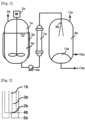
- the separation of the solvent from the copolymer (P) solution can be, for example, carried out by using an apparatus as shown in Fig. 1 . That is, a storage tank 1a is provided with a stirrer 2a, a jacket 3a, and an inert gas feed port 4a, and an immanent copolymer (P) solution 5a can be heated by using the jacket in the presence of an inert gas under pressure conditions under which the solvent does not volatilize while stirring.
- the copolymer (P) solution is fed into a pump 6a through pressurization with the inert gas.
- the copolymer (P) solution is heated to a desired temperature by a heater 7a and then discharged from a nozzle 8a.
- the pressure of the copolymer (P) solution in a section between the pump and the nozzle can be controlled by balance between a pressure increase by discharge from the pump and a pressure decrease by discharge from the nozzle.
- the nozzle 8a is connected with a takeout tank 9a, and the copolymer (P) heated to the desired temperature is discharged from the nozzle 8a in an inert gas stream. Due to the matter that the discharged copolymer (P) solution has a high temperature and a specified linear velocity, the solvent is promptly evaporated and separated from the copolymer (P).
- an inert gas at 0 to 200°C is continuously fed from an inert gas feed port 10a, and the solvent separated from the copolymer (P) solution is removed from an exhaust port 11a to the outside of the system together with the inert gas.
- a copolymer (P) 12a having been separated from the solvent is accumulated in a lower portion of the takeout tank 9a and can be continuously taken out from a transfer port 13a to the outside of the system.
- the storage tank 1a is not particularly limited with respect to a structure thereof so long as it is able to store the copolymer (P) solution in an inert gas atmosphere and has a function to feed the copolymer (P) solution into the pump; however, it is preferred that the storage tank 1a has a stirrer, a jacket, and an inert gas feed port for stable feed into the pump.
- the solid component concentration (Ts) of the copolymer (P) solution is regulated to an appropriate range as mentioned previously.
- a solution resulted from production of the copolymer (P) in the storage tank can also be used as it is.
- a stirring blade connected in the stirrer 2a is not particularly limited, and examples thereof include a maxblend blade, a fullzone blade, a paddle blade, a propeller blade, a turbine blade, a fan turbine blade, a pfaudler blade, a brumargin blade, and the like. A combination of any two or more thereof may also be used. Especially, in the case where the viscosity of the copolymer (P) solution is high, use of a maxblend blade or a fullzone blade is preferred from the standpoint of feeding the copolymer (P) solution having stable temperature and viscosity into the pump 6a. Though a stirring method may be either upper stirring or lower stirring, the upper stirring blade is preferred from the standpoint of simplifying a cleaning operation of the apparatus and a maintenance checkup.
- the jacket 3a is not particularly limited with respect to a structure thereof, and examples thereof include a full jacket type, a blowout nozzle-equipped jacket, a spiral baffle-equipped jacket, a split-coil type jacket, a two-stage type jacket, a dimple type jacket, an inner jacket, and the like. A combination of any two or more thereof may also be used. Especially, it is preferred to use a full jacket from the standpoints of a cleaning operation of the apparatus, a maintenance checkup, and apparatus costs.
- a heat transfer medium is not limited, and examples thereof include a heated oil, warm water, steam, and the like. Among them, steam is preferably used from the standpoints of easiness of temperature control, easiness of availability, and price.
- the inert gas is selected from a nitrogen gas, an argon gas, and a helium gas. Among them, a nitrogen gas is preferred in view of the fact that it is not only readily available but also inexpensive.
- a nitrogen gas is preferred in view of the fact that it is not only readily available but also inexpensive.
- the pressure of the inert gas that pressurizes the copolymer (P) solution is lower than a saturated vapor pressure of the solvent, there is a case where a long-term residual material is generated due to attachment of the copolymer (P) onto an inner wall of the storage tank and incorporated into the product.
- the case where the pressure of the inert gas is too high leads to an increase of instrument costs to be caused due to an increase of withstand pressure of the storage tank.
- a total pressure of the inside of the storage tank in a pressurized state with the inert gas is preferably in a range of 0.1 to 5.0 MPaG, and more preferably in a range of 0.5 to 3.0 MPaG.
- the "MPaG" as the pressure expression means a gauge pressure.
- the pump 6a is not particularly limited with respect to a kind thereof so long as it is a pump capable of subjecting the copolymer (P) solution to solution sending in a section between the pump and the nozzle at a discharge pressure higher than the saturated vapor pressure of the solvent, and examples thereof include a piston pump, a plunger pimp, a diaphragm pump, a gear pump, a vane pump, a screw pump, and the like.
- a plunger pump and a gear pump are preferred, and from the viewpoint of homogenizing the shape of the resulting copolymer (P), a plunger pump capable of discharging the copolymer (P) solution from the nozzle at a fixed temperature without causing a pulsating flow is more preferred for the use.
- the present invention includes a step (Step B) of heating the copolymer (P) solution obtained in the Step A such that a temperature T (°C) is in a range of ⁇ (225 - 1.9 ⁇ Ts) ⁇ T ⁇ (310 - 1.9 ⁇ Ts) ⁇ .
- Step C by discharging the copolymer (P) solution heated in the Step B from the nozzle at a linear velocity of 1 to 100 m/sec, the solvent is vaporized and separated, whereby the copolymer (P) can be obtained.
- the temperature T is preferably 130°C or higher.
- the temperature T is preferably 300°C or lower. That is, it is preferred to undergo the heating such that the temperature T (°C) is in a range of ⁇ 130 ⁇ (225 - 1.9 ⁇ Ts) ⁇ T ⁇ (310 - 1.9 ⁇ Ts) ⁇ 300 ⁇ .
- the temperature T is preferably in a range of 170 to 275°C, and in the case where the Ts is in a range of (10 ⁇ Ts ⁇ 25), the temperature T is more preferably in a range of 200 to 275°C.
- a heating method of the copolymer (P) solution is not particularly limited.
- the heating may be performed by the storage tank 1a, or the heating may be performed by the heater 7a; however, it is preferred to perform the heating under a pressure under which the solvent is not volatilized.
- a heating time is preferably within 30 minutes, and more preferably within 10 minutes.
- Examples of the heater 7a include a combustion heater, an electric heater, a heat exchange type heater, and the like, and a combination of any two or more thereof may also be used. It is preferred to use a heat exchange type heater from the standpoint of lowering the risk of a fire to be caused due to chemical leakage from a piping.
- Examples of a type to be used as the heat exchange type heater include a multi-tubular type, a hairpin type, a coil type, a double tube type, a plate type, a spiral type, and the like.
- a vertical multi-tubular type heater (shell-and-tube type heater) in which the copolymer (P) solution is allowed to pass into the tube side is preferred from the standpoint of easiness of cleaning.
- a heat transfer area of the vertical multi-tubular type heater can be set according to a temperature and a flow rate of the heat transfer medium, a flow amount of the copolymer (P) solution, and so on.
- preheating in the storage tank 1a Prior to heating to the aforementioned temperature T by the heater 7a, preheating in the storage tank 1a may be performed. As a preheating temperature of the copolymer (P) solution is made higher, the feed of the copolymer (P) solution into the pump becomes stable due to a lowering of the solution viscosity. However, when the preheating temperature is too high, decomposition or discoloration with time of the copolymer (P) is caused, and hence, the preheating temperature is preferably in a range of 30 to 140°C, and more preferably in a range of 50 to 100°C.
- the present invention includes a step (Step C) of discharging the copolymer (P) solution heated in the Step B from any one nozzle selected from a rotary wheel atomizer, a two-fluid nozzle atomizer, and a pressure nozzle atomizer at a linear velocity of 1 to 100 m/sec to atomize the copolymer (P) solution and a step of separating the solvent crom the copolymer (P) in an inert gas stream at 10 to 80°C.
- any one nozzle selected from a rotary wheel atomizer, a two-fluid nozzle atomizer, and a pressure nozzle atomizer ones incorporated into commercially available spray dryers from GEA, Inc. and so on can be used.
- the nozzle design is described in, for example, K. Masters: “Spray Drying Handbook", John Wiley and Sons, New York (1979 ), etc.
- the rotary wheel atomizer is one for cutting the heated copolymer (P) solution by shearing of a rotary disk, and the size and distribution, and so on of particles of the copolymer (P) can be controlled by a rotation rate of the rotary disk.
- the two-fluid nozzle atomizer is able to control the shape of the copolymer (P) obtained by feeding, as a high-speed gas, an inert gas or steam, or the like into the heated copolymer (P) solution from the outside.
- the two-fluid nozzle atomizer may be an internal mixing nozzle in which the inert gas or steam and the heated copolymer (P) solution are mixed under pressure prior to discharge, and the mixture is then discharged from the nozzle, or may be an external mixing nozzle in which the copolymer (P) solution is discharged from the nozzle and immediately thereafter, brought into contact with the inert gas or steam.
- the pressure atomizer is a single-fluid atomizer in which the pressure of the heated copolymer (P) solution is converted into a kinetic energy to generate a fast relative velocity against the ambient gas.
- the atomizer with a simple opening is one for jetting the liquid at a high speed through a small round-shaped hole.
- the nozzle may be a single-hole nozzle having a single channel of the heated copolymer (P) solution, or may be a multi-hole nozzle having two or more channels of the heated copolymer (P) solution.
- the copolymer (P) has such properties that it is hardly re-dissolved in a solvent vapor, and in the case of using a multi-hole nozzle, when one of the channels is once plugged, the pressure tends to increase in each channel, and on a long-term continuous operation, the shape of the obtained copolymer (P) changes with time. Accordingly, from the viewpoint of obtaining the copolymer (P) whose shape is stable in the long-term continuous operation, it is preferred to use a single-hole nozzle.
- a pressure nozzle atomizer is more preferably used in view of the matter that a heated inert gas or steam is not necessary.
- FIG. 2 A diagrammatic view of a pressure nozzle atomizer is shown in Fig. 2 .
- the pressure nozzle atomizer is configured of a stem 1b and a body 2b, and a copolymer (P) solution 3b passes through a gap between a disk of the tip of the stem 1b and a contact port 4b between the disk and the body and is subsequently discharged from a discharge port 5b into the takeout tank.
- P copolymer
- the linear velocity on discharging the copolymer (P) solution from the nozzle is defined as a maximum linear velocity in the case where the solution is considered to pass through a section between the contact port 4b of the disk with the body and the discharge port 5b.
- an opening degree of the nozzle tip can be regulated by an actuator according to an internal pressure of the piping.
- the pressure of the copolymer (P) solution immediately before it is discharged from the nozzle is preferably in a range of 0.5 to 50 MPaG, and more preferably in a range of 0.5 to 25 MPaG. So long as the pressure of the copolymer (P) solution falls within this range, the withstand pressure to be designed regarding each of the pump, the heater, and the nozzle can be decreased, and the equipment costs can be reduced.
- Examples of a shape of the disk that is a tip portion of the stem 1b include a cone, an elliptic cone, a triangular pyramid, a quadrangular pyramid, a polygonal pyramid, a cylinder, an elliptic cylinder, a triangular prism, a quadrangular prism, a polygonal prism, and the like. From the standpoint of stabilizing the dimensions of a metal worked product, those mainly composed of a conical structure are preferred.
- Examples of a channel of the body 2b include a cone, an elliptic cone, a triangular pyramid, a quadrangular pyramid, a polygonal pyramid, a cylinder, an elliptic cylinder, a triangular prism, a quadrangular prism, a polygonal prism, a curved channel, and the like. From the standpoint of stabilizing the dimensions of a metal worked product, those mainly composed of a conical structure are preferred.
- Examples of a nozzle configured of a disk having a cylindrical or conical shape, etc. and a body having a cylindrical or conical shape, etc. include nozzles 1c to 20c shown in Fig. 3 .
- Examples of the body include shapes 1c to 8c.
- the body may be in a cylindrical shape, may be in a shape of constriction structure, or may be in a curved shape.
- the width and length of the channel are not limited.
- examples of the disk include shapes 9c to 15c.
- the disk may be in a conical shape or a curved surface shape, or may be in a shape in which a part of a cone or curved shape is cut, or the cut portion is joined with another shape.
- the width and length of the channel are not limited.
- the shapes 16c to 20c each having such a structure that when closing the nozzle, the disk and the body come into good contact with each other, are preferred.
- a nozzle having such a structure by allowing the stem to move up and down, it becomes possible to control the pressure and linear velocity relative to wide-ranging viscosity and flow rate of the copolymer (P) solution.
- the aforementioned nozzle is connected with the takeout tank, and it vaporizes and separates the solvent from the copolymer (P) solution discharged from the nozzle tip and allows the copolymer (P) to drop toward the lower portion of the takeout tank, followed by taking out the copolymer (P) batchwise or continuously from the takeout tank to the outside of the system.
- the separation of the solvent is performed in an inert gas stream at 0 to 200°C.
- the takeout tank is provided with an inert gas feed port, an exhaust port of the gaseous solvent, and a carry-out port of the copolymer (P).
- the nozzle installation position and the shape of the takeout tank are not particularly limited, from the standpoints of inhibiting fusion of the discharged copolymer (P) onto the inner wall of the takeout tank and reducing the amount of the inert gas used, a cylindrical shape having an inside diameter such that the copolymer (P) discharged from the nozzle does not come into direct contact with the inner wall of the takeout tank is preferred, and it is preferred that the nozzle is installed in the center of the top of the takeout tank.
- connection positions of the inert gas feed port and the exhaust port are not particularly limited, from the standpoint of inhibiting fusion among the copolymers (P), it is preferred that the inert gas feed port is installed in the lower portion of the takeout tank, whereas the exhaust port is installed in the upper portion of the takeout tank. In addition, from the standpoint of inhibiting fusion among the copolymers (P), it is more preferred that an air hole-provided flat board as a partition board or a funnel is installed between an accumulation portion of the copolymer (P) and a vapor phase portion, and the inert gas is allowed to pass in an upflow state from the underside thereof.
- the inert gas may be fed through a usual piping, may be fed so as to generate a gas stream, or may be used by generating a gas stream in a vapor phase portion by using a stirring blade separately installed in the inside of the takeout tank.
- the inert gas which can be used herein include a nitrogen gas, an argon gas, a helium gas, and the like. Among them, a nitrogen gas is preferred in view of the matter that it is not only easily available but also inexpensive.
- a volume of the takeout tank is not particularly limited, a residence time of the inert gas is preferably 0.1 to 5 minutes, and from the viewpoints of reducing the amount of the inert gas used and inhibiting the fusion of the copolymer, it is preferred to regulate the volume of the takeout tank such that the residence time of the inert gas is in a range of 0.1 to 1 minute.
- a temperature of the inert gas is 10 to 80°C, it is preferably 10 to 50°C.
- the amount of the inert gas used is in a range of 10 to 5,000 NL, and preferably in a range of 50 to 2,000 NL in terms of an amount of the inert gas used per kg of the solvent of the copolymer (P) solution.
- the "NL" expresses a normal liter and means a volume of the inert gas at 0 MPaG and 0°C and at a humidity of 0%.
- an internal pressure of the takeout tank can be properly set, if desired, it is preferably 500 kPaG or less, and more preferably 100 kPaG or less.
- the copolymer (P) accumulated in the bottom can be transferred batchwise or continuously to the outside of the system. From the standpoint of inhibiting the fusion among the copolymers (P), it is preferred to continuously transfer the copolymer (P) by using, for example, a gas stream of an inert gas or the like, or an instrument, such as a conveyor, etc.
- the copolymer (P) may be transferred by using a gas stream of an inert gas or the like, or may be transferred by using an instrument, such as a conveyor, etc.
- the copolymer (P) is transferred together with the gaseous solvent and the inert gas
- a closed type conveyor examples include a belt conveyor, a chain conveyor, a roller conveyor, a screw conveyor, a vibrating conveyor, an elevating conveyor, and the like.
- a screw conveyor is preferred from the standpoints of easiness of cleaning and maintenance checkup.
- the screw conveyor may be of either a horizontal type or a vertical type.
- the copolymer (P) can be obtained more simply with a less energy consumption without using hot water as in the conventional steam stripping method and without requiring a dehydration/drying step.
- An amount of the residual solvent contained in the resulting copolymer (P) is typically 2 mass% or less, and more preferably 1 mass% or less.
- the copolymer (P) in a fibrous form is readily obtained.
- the copolymer (P) is a fibrous copolymer, it is low in a bulk density and excellent in oil absorptivity, as compared with copolymers in a pellet shape or a crumb shape.
- the "fibrous copolymer” as referred to in the present invention means a copolymer having a shape in which a diameter is 0.1 mm or more, a length is 1 mm or more, and a ratio of the length to the diameter is 5 times or more, and preferably 10 times or more.
- the bulk density (g/mL) of the resulting fibrous copolymer is 0.02 to 0.20 g/mL, and preferably 0.05 to 0.15 g/mL from the viewpoint of excellent oil absorptivity.
- the "bulk density” means a value obtained in a manner of filling the copolymer in a container having an already-known volume and dividing the volume including voids by the mass of the copolymer.
- an oil absorption rate that is an indicator of the oil absorptivity is 10 to 50.
- the copolymer (P) may be crushed more finely, if desire, and the copolymer (P) may be charged into an extruder to convert into a porous pellet, or may be mixed with an oil or the like to convert into an oil-extended pellet.
- the copolymer (P) obtained by the production method of the present invention can also be processed into a resin composition upon addition with other copolymer or an additive (e.g., a heat stabilizer, an ultraviolet absorber, an antioxidant, a flame retardant, a coloring agent, a lubricant, a release agent, a filler, etc.), if desired.
- an additive e.g., a heat stabilizer, an ultraviolet absorber, an antioxidant, a flame retardant, a coloring agent, a lubricant, a release agent, a filler, etc.
- Such other polymer is not particularly limited and can be properly selected according to an application.
- examples thereof include polydienes (e.g., polybutadiene, polyisoprene, polychloroprene, poly(2-ethylbutadiene), poly(2-butylbutadiene), etc.), ring-opening metathesis polymers of cycloolefins (e.g., polyoctenylene, polypentenylene, polynorbornene, etc.), polyethylene, polypropylene, polystyrene, a copolymer of ethylene and styrene, a copolymer of acrylonitrile and styrene, a copolymer of acrylonitrile, butadiene, and styrene, polyvinyl chloride, polyethylene terephthalate, polycarbonate, polyamides, polybutylene terephthalate, polyoxymethylene, polyacetal, polyphenylene ether, poly
- antioxidants examples include 2,5-di-tert-butylhydroquinone, 2,6-di-tert-butyl-p-cresol, 4,4'-thiobis(6-tert-butylphenol), 2,2'-methylene-bis(4-methyl-6-tert-butylphenol), octadecyl-3-(3',5'-di-tert-butyl-4'-hydroxyphenyl)propionate, 4,4'-thiobis(6-tert-butylphenol), 2-tert-butyl-6-(3-tert-butyl-2-hydroxy-5-methylbenzyl)-4-methylphenyl acrylate, pentaerythritol tetrakis(3-laurylthiopropionate), 2,6-di-(tert-butyl)-4-methylphenol, 2,2-methylenebis(6-tert-butyl-p-cresol), triphenyl phosphite, tris
- Examples of the flame retardant include metal salts of stannous acid, such as zinc stannate, zinc hydroxystannate, magnesium stannate, cobalt stannate, sodium stannate, potassium stannate, etc.; metal salts of boric acid, zinc borate, calcium borate, magnesium borate, etc.; antimony trioxide, antimony pentoxide, sodium antimonate, sodium oxide, tin oxide, zinc oxide, iron oxide, magnesium hydroxide, calcium hydroxide, kaolin clay, calcium carbonate, and the like.
- filler examples include silica, silica alumina, alumina, titanium oxide, zinc oxide, boron nitride, talc, mica, potassium titanate, calcium silicate, magnesium sulfate, aluminum borate, asbestos, glass beads, carbon black, graphite, molybdenum disulfide, polytetrafluoroethylene, and the like.
- the copolymer (P) which is obtained by the production method of the present invention is usable in fields of electric and electronic components, automotive components, various industrial components, daily necessities, and so on.
- the hydride of the copolymer (P) has excellent properties in impact resilience and low-temperature properties
- the hydride of the copolymer (P) is usable as a modifier for improving impact resistance, low-temperature properties, processability, and so on of thermoplastic resins, and for example, when combined with a liquid softening agent, such as an oil, etc., a plasticizer, and a thermoplastic resin, such as polypropylene, etc.
- the hydride of the copolymer (P) can be suitably used as a material for various industrial components, such as electrical wire cables, etc., automotive components, and so on.
- Isoprene manufactured by Kuraray Co., Ltd., from which moisture and a polymerization inhibitor were removed with Molecular Sieves 3A and neutral active alumina and then substituted with nitrogen, was used.
- Stabilizer-containing styrene manufactured by Wako Pure Chemical Industries, Ltd., from which moisture and a polymerization inhibitor were removed with neutral active alumina and then substituted with nitrogen, was used.
- Triisobutylaluminum manufactured by Nippon Aluminum Alkyls, Ltd. was used as it was.
- a weight average molecular weight (Mw) and a molecular weight distribution (Ma/Mn) of a polymer obtained in each of the Examples and Comparative Examples were measured by means of gel permeation chromatography (hereinafter referred to as "GPC") and expressed in terms of standard polystyrene.
- the measurement conditions are as follows.
- the 1 H-nuclear magnetic resonance spectroscopy (hereinafter abbreviated as " 1 H-NMR analysis") was performed.
- the number of double bonds (mol) before hydrogenation relative to 1 mol of styrene can be calculated from an area integrated value of a styrene site of 1 H-NMR of a copolymer not subjected to hydrogenation and an area integrated value of a conjugated diene double bond site.
- the number of double bonds (mol) after hydrogenation of a hydrogenated copolymer having been subjected to hydrogenation relative to 1 mol of styrene can be calculated.
- a difference between the number of double bonds (mol) before hydrogenation and the number of double bonds (mol) after hydrogenation is the number of hydrogenated double bonds (mol), and mol% as a proportion of the number of hydrogenated double bonds (mol) to the number of double bonds (mol) before hydrogenation was defined as the hydrogenation rate (%).
- the measurement conditions are as follows.
- a nozzle linear velocity on discharging the copolymer (P) solution was determined in the following manner.
- a conical disk is one prepared by cutting a cone having a cone angle of 11.4° and a bottom diameter of 5.58 mm at a position where the diameter is 0.42 mm, and a body is one having a shape coincident with the conical disk and being cut at a position where an opening having a diameter of 0.55 mm is formed in a tip portion thereof.
- a lifting distance of a stem is defined as a nozzle opening degree, and the nozzle opening degree H (mm) and a cross-sectional area S (mm 2 ) at which a maximum linear velocity is achieved were calculated from the structure of the pressure nozzle atomizer according to the following equations.
- the nozzle linear velocity (m/sec) was calculated from the above-obtained cross-sectional area S (mm 2 ) and a solution flow rate F (L/hr) of the copolymer (P) solution according to the following equation.
- a mass (g) after drying 10 g of an obtained fibrous copolymer at 0.1 Pa and 105°C for one hour was weighed, a mass change (g) thereof was defined as an amount (g) of the residual solvent contained in the copolymer before drying, and a mass% of the amount (g) of the residual solvent relative to 10 g of the fibrous copolymer before drying was defined as an amount (mass%) of the residual solvent.
- a diameter (mm) and a length (mm) of a fibrous copolymer obtained in each of the following Examples were measured by analyzing image digital information obtained by photographing a sample composed of a single fibrous copolymer with ADK-1100 (11 mega-pixel CCD camera), manufactured by Flovel Co., Ltd. by using Image-Pro Plus ver. 5.1, manufactured by Flovel Co., Ltd. Five samples of the fibrous copolymer having an average shape were measured, respectively, and average values thereof were adopted as a measured diameter (mm) and a measured length (mm), respectively.
- ADK-1100 11 mega-pixel CCD camera
- the copolymer was filled up to a mark of 100 mL in a 100-mL metering cylinder having an already-known mass, a difference in mass before and after filling the copolymer was considered as a mass (g) of 100 mL of the copolymer, and a value obtained by dividing the mass (g) per 100 mL of the copolymer by a volume (100 mL) was defined as the bulk density (g/mL).
- An oil absorption rate of a copolymer obtained in each of the following Examples and Comparative Examples was determined by the following method. In a 500-mL beaker, Process Oil PW90 (300 g) was charged at 25°C, and subsequently, the copolymer (10 g) was charged and allowed to stand for 30 minutes, thereby impregnating with the Process Oil PW90. This was filtered with a 200-mesh nylon-made filter cloth and allowed to stand on the filter cloth for one hour.
- a total pressure was 0.4 MPaG, and a liquid temperature was 70 to 80°C. Thereafter, 470.6 g (4.5 mol) of styrene was forcedly fed with a nitrogen gas, and the contents were polymerized for one hour. A total pressure was 0.5 MPaG, and a liquid temperature was 70 to 80°C. Thereafter, 4.00 g of a cyclohexane solution of 20.0 mmol/g of ethanol (80.0 mmol as ethanol) was forcedly fed with a nitrogen gas to terminate the polymerization, followed by cooling to 20°C. There was thus obtained a copolymer solution.
- copolymer solution A 5 g was dried at 60°C for one hour.
- the GPC analysis revealed that the copolymer A had a monomodal peak, a weight average molecular weight Mw of 44,400, and a molecular weight distribution Mw/Mn of 1.02.
- a total molar number of isoprene of the copolymer A relative to a total molar number of styrene is clear from the amounts of the chemicals charged for polymerization, whereas a molar number of the non-hydrogenated double bond derived from isoprene of the copolymer A relative to a total molar number of styrene is clear from the 1 H-NMR analysis.
- the hydrogenation rate as a proportion of the material hydrogenated with the double bond derived from isoprene was 98.7%.
- the copolymer A was a (15.0 mass% of styrene block)/(70.0 mass% of hydrogenated isoprene block)/(15.0 mass% of styrene block) copolymer, and the solution of the copolymer A contained 24.7 mass% of the copolymer A.
- the 20-liter autoclave used for the polymerization and hydrogenation was used as a storage tank 1d. Nitrogen was fed from a nitrogen feed port 2d and pressurized to 0.5 MPaG, and a copolymer solution was heated to 70°C by using a steam jacket 5d while stirring at 200 rpm with a stirrer 4d.
- a preheated copolymer solution 7d was subjected to solution sending to a plunger pump 8d, passed through an electric heater 9d heated at 240°C at a solution flow rate of 7.3 L/hr by using a pump 8d, and then discharged from a pressure nozzle atomizer 12d, thereby separating the solvent.
- the nozzle opening degree was 0.8 mm
- the nozzle linear velocity was 16.2 m/sec
- the solution pressure at a pressure gauge 10d was 3.4 MPaG
- the solution temperature at a thermometer 11d was 234°C.
- nitrogen at 27°C was fed at a rate of 23.4 NL/min, namely in a nitrogen amount of 330 NL/kg per kg of the solvent, and a gas composed of this nitrogen and the solvent vapor was exhausted from an exhaust port 16d to the outside of the system.
- the internal pressure of the takeout tank was 16 kPaG at a pressure gauge 17d, and the internal temperature of the top of the takeout tank was 89.5°C at a thermometer 18d.
- the operation was performed for 30 minutes to obtain a fibrous copolymer A 19d.
- a partition was provided at a knife gate valve 20d, and a recovery container 21d was then separated to obtain the fibrous copolymer A.
- the GPC analysis revealed that the fibrous copolymer A had a weight average molecular weight Mw of 44,400 and a molecular weight distribution Mw/Mn of 1.02, and thus, no change before and after the solvent removal was observed.
- the amount of the residual solvent was 0.43 mass%.
- the fiber of the fibrous copolymer A had a diameter of 0.12 mm and a length of 1.73 mm.
- the bulk density was 0.05 g/mL.
- the oil absorption rate was 13.3.
- a solution containing 24.7 mass% of the copolymer A was produced in the same method as in Example 1, and 3,640 g of cyclohexane was then distilled off, thereby obtaining a copolymer solution containing 34.6 mass% of the copolymer A.
- the copolymer solution was passed through the electric heater at a solution flow rate of 7.3 L/hr by using the pump and then discharged from the pressure nozzle atomizer in the same manner as in Example 1.
- the nozzle opening degree was 1.2 mm
- the nozzle linear velocity was 10.0 m/sec
- a solution pressure was 2.5 MPaG
- a solution temperature was 232°C.
- nitrogen at 27°C was fed at a rate of 23.4 NL/min, namely in a nitrogen amount of 380 NL/kg per kg of the solvent, and a gas composed of this nitrogen and the solvent vapor was exhausted from the exhaust port to the outside of the system.
- the internal pressure of the takeout tank was 17 kPaG, and the internal temperature of the top of the takeout tank was 92.5°C. The operation was performed for 30 minutes to obtain a fibrous copolymer A.
- the amount of the residual solvent was 0.93 mass%.
- the fiber of the fibrous copolymer A had a diameter of 0.11 mm and a length of 1.68 mm.
- the bulk density was 0.06 g/mL.
- the oil absorption rate was 13.5. The results are summarized in Table 1.
- a copolymer solution containing 34.6 mass% of the copolymer A was produced in the same method as in Example 2.
- the copolymer solution was passed through the electric heater at a solution flow rate of 5.8 L/hr by using the pump and then discharged from the pressure nozzle atomizer in the same manner as in Example 1.
- the nozzle opening degree was 0.93 mm
- the nozzle linear velocity was 10.8 m/sec
- the solution pressure was 3.3 MPaG
- the solution temperature was 234°C.
- nitrogen at 27°C was fed at a rate of 23.4 NL/min, namely in a nitrogen amount of 460 NL/kg per kg of the solvent, and a gas composed of this nitrogen and the solvent vapor was exhausted from the exhaust port to the outside of the system.
- the internal pressure of the takeout tank was 18 kPaG, and the internal temperature of the top of the takeout tank was 87.5°C. The operation was performed for 30 minutes to obtain a fibrous copolymer A.
- the amount of the residual solvent was 0.49 mass%.
- the fiber of the fibrous copolymer A had a diameter of 0.13 mm and a length of 2.89 mm.
- the bulk density was 0.05 g/mL.
- the oil absorption rate was 14.5. The results are summarized in Table 1.
- a copolymer solution was discharged from the pressure nozzle atomizer in the same method as in Example 3. From the inert gas feed port, nitrogen at 107°C was fed at a rate of 7.0 NL/min, namely in a nitrogen amount of 140 NL/kg per kg of the solvent, and a gas composed of this nitrogen and the solvent vapor was exhausted from the exhaust port to the outside of the system.
- the internal pressure of the takeout tank was 7 kPaG, and the internal temperature of the top of the takeout tank was 92.0°C. The operation was performed for 30 minutes to obtain a fibrous copolymer A.
- the amount of the residual solvent was 0.21 mass%.
- the fiber of the fibrous copolymer A had a diameter of 0.47 mm and a length of 200 mm or more.
- the bulk density was 0.10 g/mL.
- the oil absorption rate was 13.8. The results are summarized in Table 1.
- a solution containing 24.7 mass% of the copolymer A was produced in the same method as in Example 1, and 6,530 g of cyclohexane was then distilled off, thereby obtaining a copolymer solution containing 50.9 mass% of the copolymer A.
- the copolymer solution was passed through the electric heater at a solution flow rate of 5.0 L/hr by using the pump and then discharged from the pressure nozzle atomizer in the same manner as in Example 1.
- the nozzle opening degree was 1.94 mm
- the nozzle linear velocity was 5.8 m/sec
- the solution pressure was 3.2 MPaG
- the solution temperature was 209°C.
- nitrogen at 27°C was fed at a rate of 23.4 NL/min, namely in a nitrogen amount of 730 NL/kg per kg of the solvent, and a gas composed of this nitrogen and the solvent vapor was exhausted from the exhaust port to the outside of the system.
- the internal pressure of the takeout tank was 12 kPaG, and the internal temperature of the top of the takeout tank was 96.2°C. The operation was performed for 30 minutes to obtain a fibrous copolymer A.
- the amount of the residual solvent was 0.57 mass%.
- the fiber of the fibrous copolymer A had a diameter of 0.44 mm and a length of 4.39 mm.
- the bulk density was 0.04 g/mL.
- the oil absorption rate was 11.3. The results are summarized in Table 1.
- the apparatus was operated for 2 hours in the same method as in Example 1, thereby obtaining about 2.8 kg of a fibrous copolymer A.
- a 20-liter autoclave 5,700.0 g of pentane was charged, and subsequently, 2,500 g of the obtained fibrous copolymer A was charged.
- the contents were stirred at 200 rpm with nitrogen at a total pressure of 0.5 MPaG and a liquid temperature of 80°C for 10 hours, thereby obtaining a copolymer solution containing 30.6 mass% of the copolymer A.
- the copolymer solution was passed through the electric heater at a solution flow rate of 7.3 L/hr by using the pump and then discharged from the pressure nozzle atomizer in the same manner as in Example 1.
- the nozzle opening degree was 0.80 mm
- the nozzle linear velocity was 16.2 m/sec
- the solution pressure was 4.0 MPaG
- the solution temperature was 174°C.
- nitrogen at 33°C was fed at a rate of 23.2 NL/min, namely in a nitrogen amount of 440 NL/kg per kg of the solvent, and a gas composed of this nitrogen and the solvent vapor was exhausted from the exhaust port to the outside of the system.
- the internal pressure of the takeout tank was 39 kPaG
- the internal temperature of the top of the takeout tank was 68.2°C.
- the operation was performed for 30 minutes to obtain a fibrous copolymer A.
- the amount of the residual solvent was 0.08 mass%.
- the fiber of the fibrous copolymer A had a diameter of 0.12 mm and a length of 2.47 mm.
- the bulk density was 0.07 g/mL.
- the oil absorption rate was 12.9. The results are summarized in Table 1.
- Example 1 it is noted that the copolymer solution produced through polymerization and hydrogenation by using cyclohexane can be used for the production method of the present invention as it is.
- Example 6 even in the case of using pentane having a boiling point of 36.1°C as the solvent, by the production method of the present invention, the copolymer in which the amount of the residual solvent is low, the bulk density is small, and the oil absorption rate is excellent are obtained more simply with a less energy consumption as compared with the conventional method.
- a copolymer solution was prepared in the following manner and then subjected to the production method of the present invention.
- the copolymer B was composed of 38 mass% of a styrene block and 62 mass% of a hydrogenated isoprene block and had a hydrogenation rate of 98% or more, a weight average molecular weight Mw of 127,000, a molecular weight distribution Mw/Mn of 1.04, and a bulk density of 0.38 g/mL.
- the copolymer solution was passed through the electric heater at a solution flow rate of 5.8 L/hr by using the pump and then discharged from the pressure nozzle atomizer in the same manner as in Example 1.
- the nozzle opening degree was 1.13 mm
- the nozzle linear velocity was 8.5 m/sec
- the solution pressure was 3.3 MPaG
- the solution temperature was 222°C.
- nitrogen at 27°C was fed at a rate of 23.0 NL/min, namely in a nitrogen amount of 420 NL/kg per kg of the solvent, and a gas composed of this nitrogen and the solvent vapor was exhausted from the exhaust port to the outside of the system.
- the internal pressure of the takeout tank was 16 kPaG
- the internal temperature of the top of the takeout tank was 93.3°C. The operation was performed for 30 minutes to obtain a fibrous copolymer B.
- the amount of the residual solvent was 0.60 mass%.
- the fiber of the fibrous copolymer B had a diameter of 0.13 mm and a length of 1.36 mm.
- the bulk density was 0.09 g/mL.
- the oil absorption rate was 13.9. The results are summarized in Table 2.
- a hydrogenated triblock copolymer having a crumb shape which was obtained by producing a triblock polymer through anionic polymerization of styrene, a mixture of isoprene and butadiene, and styrene in this order and hydrogenating this, followed by steam stripping (the hydrogenated triblock copolymer will be hereinafter referred to as "copolymer C")
- a copolymer solution was prepared in the following manner and then subjected to the production method of the present invention.
- the copolymer C was composed of 30 mass% of a styrene block and 70 mass% of a hydrogenated isoprene/butadiene copolymer block and had a hydrogenation rate of 98% or more, a weight average molecular weight Mw of 88,000, a molecular weight distribution Mw/Mn of 1.03, and a bulk density of 0.28 g/mL.
- the copolymer solution was passed through the electric heater at a solution flow rate of 5.8 L/hr by using the pump and then discharged from the pressure nozzle atomizer in the same manner as in Example 1.
- the nozzle opening degree was 1.74 mm
- the nozzle linear velocity was 6.7 m/sec
- the solution pressure was 3.3 MPaG
- the solution temperature was 234°C.
- nitrogen at 27°C was fed at a rate of 23.3 NL/min, namely in a nitrogen amount of 440 NL/kg per kg of the solvent, and a gas composed of this nitrogen and the solvent vapor was exhausted from the exhaust port to the outside of the system.
- the internal pressure of the takeout tank was 13 kPaG
- the internal temperature of the top of the takeout tank was 94.0°C. The operation was performed for 30 minutes to obtain a fibrous copolymer C.
- the amount of the residual solvent was 1.61 mass%.
- the fiber of the fibrous copolymer C had a diameter of 0.16 mm and a length of 3.69 mm.
- the bulk density was 0.05 g/mL.
- the oil absorption rate was 13.4. The results are summarized in Table 2.
- a copolymer solution was prepared in the following manner and then subjected to the production method of the present invention.
- the copolymer D was composed of 34 mass% of a styrene block and 66 mass% of a hydrogenated butadiene block and had a hydrogenation rate of 98% or more, a weight average molecular weight Mw of 280,000, a molecular weight distribution Mw/Mn of 1.07, and a bulk density of 0.28 g/mL.
- the copolymer solution was passed through the electric heater at a solution flow rate of 8.2 L/hr by using the pump and then discharged from the pressure nozzle atomizer in the same manner as in Example 1.
- the nozzle opening degree was 1.14 mm
- the nozzle linear velocity was 11.9 m/sec
- the solution pressure was 3.8 MPaG
- the solution temperature was 243°C.
- nitrogen at 77°C was fed at a rate of 23.3 NL/min, namely in a nitrogen amount of 260 NL/kg per kg of the solvent, and a gas composed of this nitrogen and the solvent vapor was exhausted from the exhaust port to the outside of the system.
- the internal pressure of the takeout tank was 17 kPaG
- the internal temperature of the top of the takeout tank was 92.1°C. The operation was performed for 30 minutes to obtain a fibrous copolymer D.
- the amount of the residual solvent was 1.98 mass%.
- the fiber of the fibrous copolymer D had a diameter of 0.14 mm and a length of 200 mm or more.
- the bulk density was 0.08 g/mL.
- the oil absorption rate was 12.7. The results are summarized in Table 2.
- the bulk density of the copolymer B (in a crumb shape) was 0.38 g/mL, and as a result of measuring the oil absorption rate, it was found to be 9.8.
- the results are summarized in Table 3.
- the bulk density of the copolymer C (in a crumb shape) was 0.28 g/mL, and as a result of measuring the oil absorption rate, it was found to be 5.0.
- the results are summarized in Table 3.
- the present invention is applicable to copolymers of various molecular structures.
- the copolymers obtained by the production method of the present invention are higher in the oil absorption rate than the copolymers having a crumb shape.
Landscapes
- Chemical & Material Sciences (AREA)
- Chemical Kinetics & Catalysis (AREA)
- Organic Chemistry (AREA)
- Medicinal Chemistry (AREA)
- Polymers & Plastics (AREA)
- Health & Medical Sciences (AREA)
- Engineering & Computer Science (AREA)
- General Chemical & Material Sciences (AREA)
- Inorganic Chemistry (AREA)
- Materials Engineering (AREA)
- Textile Engineering (AREA)
- Addition Polymer Or Copolymer, Post-Treatments, Or Chemical Modifications (AREA)
- Graft Or Block Polymers (AREA)
- Compositions Of Macromolecular Compounds (AREA)
Claims (8)
- Verfahren zur Herstellung eines Copolymers (P) (12a, 19d), umfassend das Abtrennen eines Lösungsmittels, das in einer Copolymer-(P)-Lösung (5a, 7d) enthalten ist, die das Copolymer (P) (12a, 19d) enthält, um das Copolymer (P) (12a, 19d) zu erhalten, wobei das in der Copolymer-(P)-Lösung (5a, 7d), die das Copolymer (P) (12a, 19d) enthält, enthaltene Lösungsmittel mindestens eines ist, ausgewählt aus Isopentan, Pentan, Cyclopentan, Hexan, Cyclohexan, Isoheptan, und Heptan,wobei das Copolymer (P) (12a, 19d) mindestens ein Copolymer ist, ausgewählt aus einem Copolymer aus einer aromatischen Vinylverbindung und einem konjugierten Dien, zusammengesetzt aus mindestens einem konjugierten Dien und mindestens einer aromatischen Vinylverbindung,wobei das Copolymer (P) (12a, 19d) ein Hydrid des Blockcopolymers ist, das aus einem Polymerblock (b), der mindestens eine konjugierte Dieneinheit enthält, und einem Polymerblock (a), der mindestens eine aromatische Vinylverbindungseinheit enthält, zusammengesetzt ist, und ein gewichtsmittleres Molekulargewicht von 30.000 bis 500.000 aufweist,wobei der Polymerblock (b) einer ist, der 50 Massen-% oder mehr einer Bestandteileinheit, basierend auf dem konjugierten Dien, enthält, und der Gehalt des Polymerblocks (b) in dem Blockcopolymer 10 bis 95 Massen-% beträgt,wobei der Polymerblock (a), der mindestens eine aromatische Vinylverbindungseinheit enthält, einer ist, der 50 Massen-% oder mehr einer Bestandteileinheit, basierend auf der aromatischen Vinylverbindung, enthält, und der Gehalt des Polymerblocks (a) in dem Blockcopolymer 5 bis 90 Massen-% beträgt,wobei das Copolymer aus aromatischer Vinylverbindung und konjugiertem Dien durch Hydrierung mittels eines anionischen Flüssigphasen-Polymerisationsverfahrens unter Verwendung einer organischen Alkalimetallverbindung als einen Polymerisationsinitiator in Gegenwart eines Inertgases, eines Hydrierungskatalysators und eines Lösungsmittels, das gegenüber dem Polymerisationsinitiator inert ist, hergestellt wird und wobei die Copolymer-(P)-Lösung die Lösung des Copolymers aus aromatischer Vinylverbindung und konjugiertem Dien ist, oder eine Lösung, die hergestellt wird, indem das für die Herstellung verwendete Lösungsmittel einmal von der Lösung des Copolymers aus aromatischer Vinylverbindung und konjugiertem Dien durch ein Verfahren wie Koagulation abgetrennt wird, um einen Feststoff zu bilden, und dann der Feststoff in einem für die Abtrennung geeigneten Lösungsmittel wieder aufgelöst wird;wobei das Lösungsmittel ein gesättigtes aliphatisches Kohlenwasserstofflösungsmittel oder ein gesättigtes alicyclisches Kohlenwasserstofflösungsmittel ist, die jeweils einen Siedepunkt von 30 bis 100°C haben, wobei der Siedepunkt einen Siedepunkt bei einem Druck von 1 atm bedeutet, wobei das Lösungsmittel mindestens eines ist, das aus Isopentan, Pentan, Cyclopentan, Hexan, Cyclohexan, Isoheptan und Heptan ausgewählt ist; undwobei das Verfahren die folgenden Schritte A bis C umfasst:Schritt A: ein Schritt des Regulierens einer Feststoffkomponentenkonzentration (Ts) der Copolymer-(P)-Lösung (5a, 7d) auf einen Bereich von (5 ≤ Ts ≤ 60) in Bezug auf Massen-%,Schritt B: ein Schritt des Erwärmens der in Schritt A erhaltenen Copolymer-(P)-Lösung (5a, 7d), so dass eine Temperatur T (°C) in einem Bereich von {(225 - 1,9 × Ts) ≤ T ≤ (310 - 1,9 × Ts)} liegt, undSchritt C: ein Schritt des Ablassens der Copolymer-(P)-Lösung (5e), die in Schritt B erwärmt wurde und die Temperatur T aufweist, aus einer beliebigen Düse (8a, 12d), die aus einem Rotationsradzerstäuber, einem Zweiflüssigkeitsdüsenzerstäuber und einem Druckdüsenzerstäuber (12d) ausgewählt ist, mit einer linearen Geschwindigkeit von 1 bis 100 m/sec, um die Copolymer-(P)-Lösung (5a, 7d) zu zerstäuben, und ein Schritt des Abtrennens des Lösungsmittels von dem Copolymer (P) in einem Inertgasstrom bei 10 bis 80°C, wobei die Menge des verwendeten Inertgases in einem Bereich von 10 bis 5.000 NL liegt, ausgedrückt als Menge des verwendeten Inertgases pro kg des Lösungsmittels der Copolymer-(P)-Lösung, wobei NL das Volumen des Inertgases in normalen Litern bei 0 MPaG und 0°C und bei einer Feuchtigkeit von 0 % ist, wobei das Inertgas ausgewählt ist aus Stickstoffgas, Argongas und Heliumgas,wobei das durch den Schritt C erhaltene Copolymer (P) (12a, 19d) ein faseriges Copolymer ist, undwobei die Schüttdichte des in Schritt C erhaltenen Copolymers (P) (12a, 19d) 0,02 bis 0,20 g/mL beträgt und eine Ölabsorptionsrate davon von 10 bis 50 beträgt, wobei die Ölabsorptionsrate gemäß dem folgenden Verfahren bestimmt wird:
300 g Prozessöl PW90 werden in ein Becherglas (25°C) gefüllt, anschließend werden 10 g des Copolymers (P) eingefüllt und 30 Minuten lang stehen gelassen, wodurch es mit dem Prozessöl PW90 imprägniert wird; dieses wird mit einem 200-Mesh-Nylon-Filtertuch filtriert und eine Stunde lang auf dem Filtertuch stehen gelassen; danach wird eine Masse in Gramm des Copolymers (P) nach der Ölabsorption gewogen, und ein Wert, der durch Teilen dieser Masse in Gramm des Copolymers (P) nach Ölabsorption durch die Masse von 10 g des Copolymers (P) vor Ölabsorption erhalten wird, wird als die Ölabsorptionsrate definiert. - Verfahren zur Herstellung eines Copolymers (P) (12a, 19d) nach Anspruch 1, wobei das konjugierte Dien eines oder mehrere ist, ausgewählt aus der Gruppe, bestehend aus Butadien, Isopren, 2,3-Dimethyl-1,3-butadien, 1,3-Pentadien, 2-Methyl-1,3-pentadien, 3-Methyl-1,3-Pentadien, 1,3-Hexadien, 4,5-Diethyl-1,3-butadien, Phenyl-1,3-butadien, 4,5-Diethyl-1,3-octadien, 3-Butyl-1,3-octadien, 1,3-Cyclohexadien, 1,3,7-Octatrien, 7-Methyl-3-methylenocta-1,6-dien und 3,7,11-Trimethyl-1,3,6,10-dodecatetraen, und wobei die aromatische Vinylverbindung eine oder mehrere ist, ausgewählt aus der Gruppe, bestehend aus Styrol, α-Methylstyrol, α-Methyl-4-methylstyrol, 2-Methylstyrol, 3-Methylstyrol, 4-Methylstyrol, 2,4-Dimethylstyrol, 2,5-Dimethylstyrol, 3,4-Dimethylstyrol, 3,5-Dimethylstyrol, 2-Ethylstyrol, 3-Ethylstyrol, 4-Ethylstyrol, 4-n-Propylstyrol, 4-Isopropylstyrol, 4-tert-Butylstyrol, 4-Cyclohexylstyrol, 4-Dodecylstyrol, 2-Ethyl-4-benzylstyrol, 4-(4-Phenyl-n-butyl)styrol, 1-Vinylnaphthalin, 2-Vinylnaphthalin, 1,1-Diphenylethylen, N,N-Dimethyl-p-aminoethylstyrol, N,N-Diethyl-p-aminoethylstyrol, 1,2-Divinylbenzol, 1,3-Divinylbenzol, 1,4-Divinylbenzol, 1,2-Divinyl-3,4-dimethylbenzol, 2,4-Divinylbiphenyl, 1,3-Divinylnaphthalin, 1,2,4-Trivinylbenzol, 3,5,4'-Trivinylbiphenyl, 1,3,5-Trivinylnaphthalin und 1,5,6-Trivinyl-3,7-diethylnaphthalin.
- Verfahren zur Herstellung eines Copolymers (P) (12a, 19d) nach Anspruch 1 oder 2, wobei eine Molgewichtsverteilung des Blockcopolymers, welches das Copolymer (P) (12a, 19d) bildet, in einem Bereich von 1,0 bis 2,5 liegt.
- Verfahren zur Herstellung eines Copolymers (P) (12a, 19d) nach einem der Ansprüche 1 bis 3, wobei die Temperatur T (°C) im Schritt B in einem Bereich von 200 bis 275°C liegt.
- Verfahren zur Herstellung eines Copolymers (P) (12a, 19d) nach einem der Ansprüche 1 bis 4, wobei die Feststoffkomponentenkonzentration (Ts) der Copolymer-(P)-Lösung (5a, 7d) im Schritt A (10 ≤ Ts ≤ 35) in Masse-% beträgt.
- Verfahren zur Herstellung eines Copolymers (P) (12a, 19d) nach einem der Ansprüche 1 bis 5, wobei die lineare Geschwindigkeit im Schritt C von 5 bis 50 m/sec beträgt.
- Verfahren zur Herstellung eines Copolymers (P) (12a, 19d) nach einem der Ansprüche 1 bis 5, wobei die lineare Geschwindigkeit im Schritt C von 3 bis 30 m/sec beträgt.
- Verfahren zur Herstellung eines Copolymers (P) (12a, 19d) nach einem der Ansprüche 1 bis 7, wobei die Menge des Restlösungsmittels in dem durch Schritt C erhaltenen Copolymer (P) (12a, 19d) 2 Massen-% oder weniger beträgt.
Applications Claiming Priority (2)
| Application Number | Priority Date | Filing Date | Title |
|---|---|---|---|
| JP2014262847 | 2014-12-25 | ||
| PCT/JP2015/086336 WO2016104745A1 (ja) | 2014-12-25 | 2015-12-25 | 芳香族ビニル-共役ジエン共重合体及びその水素化物の製造方法 |
Publications (3)
| Publication Number | Publication Date |
|---|---|
| EP3239187A1 EP3239187A1 (de) | 2017-11-01 |
| EP3239187A4 EP3239187A4 (de) | 2018-08-22 |
| EP3239187B1 true EP3239187B1 (de) | 2024-09-04 |
Family
ID=56150757
Family Applications (1)
| Application Number | Title | Priority Date | Filing Date |
|---|---|---|---|
| EP15873313.9A Active EP3239187B1 (de) | 2014-12-25 | 2015-12-25 | Verfahren zur herstellung von aromatischem vinyl/konjugiertem dien-copolymer und hydrierungsprodukt davon |
Country Status (8)
| Country | Link |
|---|---|
| US (1) | US10000585B2 (de) |
| EP (1) | EP3239187B1 (de) |
| JP (1) | JP6566577B2 (de) |
| KR (1) | KR102467548B1 (de) |
| CN (1) | CN107108778B (de) |
| CA (1) | CA2971833C (de) |
| SG (1) | SG11201705229UA (de) |
| WO (1) | WO2016104745A1 (de) |
Families Citing this family (11)
| Publication number | Priority date | Publication date | Assignee | Title |
|---|---|---|---|---|
| JP7203092B2 (ja) * | 2018-03-28 | 2023-01-12 | 丸善石油化学株式会社 | 水素添加石油樹脂の脱臭方法及び水素添加石油樹脂の製造方法 |
| JP7141027B2 (ja) * | 2018-07-05 | 2022-09-22 | 株式会社クラレ | 成形体 |
| KR102489249B1 (ko) * | 2018-12-03 | 2023-01-17 | 주식회사 엘지화학 | 폴리페닐렌 설파이드의 제조방법 및 제조장치 |
| KR102432563B1 (ko) * | 2018-12-18 | 2022-08-16 | 주식회사 엘지화학 | 폴리페닐렌 설파이드의 제조방법 및 제조장치 |
| CN113166473B (zh) | 2018-12-21 | 2023-10-10 | 株式会社可乐丽 | 耐油膜、耐油基材和耐油纸 |
| KR102608800B1 (ko) * | 2019-08-08 | 2023-11-30 | 주식회사 엘지화학 | 폴리페닐렌 설파이드 제조 방법 및 제조 장치 |
| CN110422354B (zh) * | 2019-08-13 | 2021-02-12 | 浙江厚达智能科技股份有限公司 | 滤气式中药灌装方法 |
| WO2021221029A1 (ja) * | 2020-04-27 | 2021-11-04 | 宇部興産株式会社 | ポリブタジエン組成物及びその製造方法、ゴム組成物、タイヤ及びゴムベルト |
| KR102640782B1 (ko) * | 2020-07-16 | 2024-02-27 | 아사히 가세이 가부시키가이샤 | 랜덤 공중합체, 크럼의 제조 방법, 및 공기 타이어 |
| KR102751390B1 (ko) * | 2021-11-25 | 2025-01-07 | 주식회사 엘지화학 | 용매 재순환 시스템 |
| WO2023096120A1 (ko) * | 2021-11-25 | 2023-06-01 | 주식회사 엘지화학 | 용매 재순환 시스템 |
Citations (2)
| Publication number | Priority date | Publication date | Assignee | Title |
|---|---|---|---|---|
| GB2243307A (en) * | 1990-04-27 | 1991-10-30 | Yamato Scient Co Ltd | Organic solvent spray dryer device |
| US5283021A (en) * | 1993-06-14 | 1994-02-01 | Chi Mei Corporation | Process for removing the solvent from an elastomeric polymer solution |
Family Cites Families (24)
| Publication number | Priority date | Publication date | Assignee | Title |
|---|---|---|---|---|
| NL6501249A (de) * | 1965-02-01 | 1966-08-02 | ||
| JPH0713091B2 (ja) | 1989-01-18 | 1995-02-15 | 旭化成工業株式会社 | 重合体の脱水・乾燥方法 |
| JPH0678376B2 (ja) | 1990-07-31 | 1994-10-05 | 旭化成工業株式会社 | ブロック共重合体の製造方法 |
| JP2859515B2 (ja) | 1993-06-25 | 1999-02-17 | 住友電気工業株式会社 | 光スイッチ |
| EP0992520B1 (de) | 1998-04-28 | 2007-03-07 | Asahi Kasei Kabushiki Kaisha | Poröse trockene körnchen aus hydriertem blockcopolymer |
| US6451914B1 (en) * | 1999-04-26 | 2002-09-17 | Dyneon Gmbh & Co. Kg | Emulsion polytetrafluoroethylene micropowder additive for fiber-forming plastics |
| JP4334063B2 (ja) | 1999-06-14 | 2009-09-16 | 旭化成ケミカルズ株式会社 | ブロック共重合体の製造方法 |
| ES2267575T3 (es) * | 1999-10-28 | 2007-03-16 | Asahi Kasei Kabushiki Kaisha | Procedimiento de eliminacion de un disolvente de hidrocarburo de una solucion de copolimero bloque hidrogenado en disolvente de hidrocarburo. |
| DE60115341T2 (de) * | 2000-06-22 | 2006-07-06 | Jsr Corp. | Verfahren zur Gewinnung eines Polymers aus einer Lösung |
| US6962960B1 (en) * | 2002-01-09 | 2005-11-08 | Fina Technology, Inc. | Method for removing volatiles from a block copolymer |
| JP4001530B2 (ja) * | 2002-09-04 | 2007-10-31 | 電気化学工業株式会社 | ブロック共重合体の製造方法 |
| JP2004155851A (ja) * | 2002-11-05 | 2004-06-03 | Denki Kagaku Kogyo Kk | ブロック共重合体の製造方法 |
| JP5186920B2 (ja) * | 2005-02-18 | 2013-04-24 | Jsr株式会社 | 重合体の回収方法及び重合体 |
| JP2006241176A (ja) * | 2005-02-28 | 2006-09-14 | Nippon Zeon Co Ltd | 重合体組成物の回収方法 |
| JP5059459B2 (ja) | 2007-03-23 | 2012-10-24 | 旭化成ケミカルズ株式会社 | 組成の異なるブロック共重合体又はその水添物を含む混合物の製造方法 |
| KR100910255B1 (ko) * | 2007-10-08 | 2009-07-31 | 금호석유화학 주식회사 | 수소화된 공역디엔계 중합체의 제조방법 |
| JP5156349B2 (ja) | 2007-11-22 | 2013-03-06 | 旭化成ケミカルズ株式会社 | ブロック共重合体又はその水添物のペレットの製造方法 |
| IT1391942B1 (it) | 2008-11-14 | 2012-02-02 | Polimeri Europa Spa | Procedimento per l'ottenimento di un elastomero in fase solida a partire dalla sua soluzione polimerica |
| TWI388577B (zh) | 2008-12-30 | 2013-03-11 | Tsrc Corp | 製造高度氫化的嵌段共聚物之方法 |
| EP2368918A1 (de) | 2010-03-24 | 2011-09-28 | LANXESS Deutschland GmbH | Verfahren zur Herstellung von wasser- und lösemittelfreien Polymeren |
| JP5403830B2 (ja) * | 2010-06-24 | 2014-01-29 | ダウ グローバル テクノロジーズ エルエルシー | カルボキシル化スチレンブタジエンベースのラテックスのブレンドから製造された再分散可能なポリマー粉体 |
| TWI520769B (zh) * | 2010-09-22 | 2016-02-11 | Jsr Corp | Separating device for solid polymer, separation method of solid polymer, and method for producing rubber material |
| CN103189406B (zh) * | 2010-10-28 | 2016-01-20 | 日本弹性体株式会社 | 氢化嵌段共聚物集料及其制造方法 |
| JP5904125B2 (ja) * | 2011-01-21 | 2016-04-13 | 日本ゼオン株式会社 | 電気化学素子用電極の製造方法および電気化学素子 |
-
2015
- 2015-12-25 US US15/538,368 patent/US10000585B2/en active Active
- 2015-12-25 KR KR1020177016863A patent/KR102467548B1/ko active Active
- 2015-12-25 CN CN201580070314.1A patent/CN107108778B/zh active Active
- 2015-12-25 EP EP15873313.9A patent/EP3239187B1/de active Active
- 2015-12-25 WO PCT/JP2015/086336 patent/WO2016104745A1/ja not_active Ceased
- 2015-12-25 SG SG11201705229UA patent/SG11201705229UA/en unknown
- 2015-12-25 JP JP2016566539A patent/JP6566577B2/ja active Active
- 2015-12-25 CA CA2971833A patent/CA2971833C/en active Active
Patent Citations (2)
| Publication number | Priority date | Publication date | Assignee | Title |
|---|---|---|---|---|
| GB2243307A (en) * | 1990-04-27 | 1991-10-30 | Yamato Scient Co Ltd | Organic solvent spray dryer device |
| US5283021A (en) * | 1993-06-14 | 1994-02-01 | Chi Mei Corporation | Process for removing the solvent from an elastomeric polymer solution |
Also Published As
| Publication number | Publication date |
|---|---|
| CN107108778B (zh) | 2019-06-21 |
| US10000585B2 (en) | 2018-06-19 |
| JPWO2016104745A1 (ja) | 2017-10-12 |
| KR20170101209A (ko) | 2017-09-05 |
| JP6566577B2 (ja) | 2019-08-28 |
| CA2971833A1 (en) | 2016-06-30 |
| WO2016104745A1 (ja) | 2016-06-30 |
| SG11201705229UA (en) | 2017-07-28 |
| KR102467548B1 (ko) | 2022-11-15 |
| CN107108778A (zh) | 2017-08-29 |
| US20180002457A1 (en) | 2018-01-04 |
| CA2971833C (en) | 2023-04-04 |
| EP3239187A4 (de) | 2018-08-22 |
| EP3239187A1 (de) | 2017-11-01 |
Similar Documents
| Publication | Publication Date | Title |
|---|---|---|
| US10000585B2 (en) | Process for producing aromatic vinyl/conjugated diene copolymer and product of hydrogenation thereof | |
| JP6105336B2 (ja) | 変性共役ジエン系重合体組成物、トレッド、サイドウォール及びタイヤ | |
| HUE026810T2 (en) | Process for the preparation of modified conjugated diene polymer, modified conjugated diene polymer and modified conjugated diene polymer composition. | |
| JP6546890B2 (ja) | 水素化重合体の製造方法 | |
| CN103189406B (zh) | 氢化嵌段共聚物集料及其制造方法 | |
| JP6097537B2 (ja) | 分岐状ブタジエン系重合体の製造方法 | |
| EP3103820A1 (de) | Neuartiger anionischer polymerisierungsinitiator und verfahren zur herstellung von konjugierten dienbasierten polymeren damit | |
| WO2010131668A1 (ja) | 分岐状共役ジエン系重合体の製造方法 | |
| EP3095799A1 (de) | Verfahren zur herstellung eines neuartigen anionischen polymerisierungsinitiators und konjugatdiensystem-copolymer damit | |
| JP6203391B2 (ja) | 共役ジエン系重合体、その製造方法及びそれを含む組成物 | |
| EP3564280B1 (de) | Copolymer aus 1,3,7-octatrien und styrol und hydrid davon | |
| JPH05255408A (ja) | カルボキシル基含有共役ジエン系重合体の製造方法 | |
| JPH10218908A (ja) | テトラヒドロピラニルメタノールのアルキルエーテルの存在下での共役ジエンとビニルアレーンのアニオン共重合 | |
| CN101205268A (zh) | 氢化共轭二烯聚合物的方法及氢化触媒组合物 | |
| KR20120040702A (ko) | 불포화된 화합물의 수소화를 위한 촉매 | |
| EP2042531B1 (de) | Blockcopolymer, zusammensetzung zur harzmodifizierung und modifizierte harzzusammensetzung | |
| JP4651413B2 (ja) | ブロック共重合体の製造方法 | |
| KR20170028410A (ko) | 공액 디엔 중합체의 제조 방법 | |
| CN101829600A (zh) | 氢化触媒组合物及其氢化方法 | |
| EP3564279A1 (de) | Copolymer von 1,3,7-octatrien und isopren, hydrid davon sowie verfahren zur herstellung des besagten copolymers | |
| JPH0713091B2 (ja) | 重合体の脱水・乾燥方法 | |
| JPH0713092B2 (ja) | 重合体の乾燥法 | |
| EP3564274B1 (de) | 1,3,7-octatrien-polymer, hydrid davon und verfahren zur herstellung des besagten polymers | |
| JP6843860B2 (ja) | ヒドロキシル化ポリオレフィンの製造方法 | |
| JPH01185304A (ja) | 変性重合体の取得方法 |
Legal Events
| Date | Code | Title | Description |
|---|---|---|---|
| STAA | Information on the status of an ep patent application or granted ep patent |
Free format text: STATUS: THE INTERNATIONAL PUBLICATION HAS BEEN MADE |
|
| PUAI | Public reference made under article 153(3) epc to a published international application that has entered the european phase |
Free format text: ORIGINAL CODE: 0009012 |
|
| STAA | Information on the status of an ep patent application or granted ep patent |
Free format text: STATUS: REQUEST FOR EXAMINATION WAS MADE |
|
| 17P | Request for examination filed |
Effective date: 20170622 |
|
| AK | Designated contracting states |
Kind code of ref document: A1 Designated state(s): AL AT BE BG CH CY CZ DE DK EE ES FI FR GB GR HR HU IE IS IT LI LT LU LV MC MK MT NL NO PL PT RO RS SE SI SK SM TR |
|
| AX | Request for extension of the european patent |
Extension state: BA ME |
|
| DAV | Request for validation of the european patent (deleted) | ||
| DAX | Request for extension of the european patent (deleted) | ||
| A4 | Supplementary search report drawn up and despatched |
Effective date: 20180723 |
|
| RIC1 | Information provided on ipc code assigned before grant |
Ipc: C08F 8/04 20060101ALI20180717BHEP Ipc: C08F 212/08 20060101ALI20180717BHEP Ipc: C08F 297/04 20060101ALI20180717BHEP Ipc: C08F 4/46 20060101ALI20180717BHEP Ipc: C08F 236/10 20060101ALI20180717BHEP Ipc: B01J 4/00 20060101ALI20180717BHEP Ipc: C08F 6/12 20060101AFI20180717BHEP Ipc: D01F 6/78 20060101ALI20180717BHEP Ipc: C08F 2/06 20060101ALI20180717BHEP |
|
| STAA | Information on the status of an ep patent application or granted ep patent |
Free format text: STATUS: EXAMINATION IS IN PROGRESS |
|
| 17Q | First examination report despatched |
Effective date: 20190613 |
|
| P01 | Opt-out of the competence of the unified patent court (upc) registered |
Effective date: 20230525 |
|
| GRAP | Despatch of communication of intention to grant a patent |
Free format text: ORIGINAL CODE: EPIDOSNIGR1 |
|
| STAA | Information on the status of an ep patent application or granted ep patent |
Free format text: STATUS: GRANT OF PATENT IS INTENDED |
|
| INTG | Intention to grant announced |
Effective date: 20240415 |
|
| GRAS | Grant fee paid |
Free format text: ORIGINAL CODE: EPIDOSNIGR3 |
|
| GRAA | (expected) grant |
Free format text: ORIGINAL CODE: 0009210 |
|
| STAA | Information on the status of an ep patent application or granted ep patent |
Free format text: STATUS: THE PATENT HAS BEEN GRANTED |
|
| AK | Designated contracting states |
Kind code of ref document: B1 Designated state(s): AL AT BE BG CH CY CZ DE DK EE ES FI FR GB GR HR HU IE IS IT LI LT LU LV MC MK MT NL NO PL PT RO RS SE SI SK SM TR |
|
| REG | Reference to a national code |
Ref country code: GB Ref legal event code: FG4D |
|
| REG | Reference to a national code |
Ref country code: CH Ref legal event code: EP |
|
| REG | Reference to a national code |
Ref country code: IE Ref legal event code: FG4D |
|
| REG | Reference to a national code |
Ref country code: DE Ref legal event code: R096 Ref document number: 602015089816 Country of ref document: DE |
|
| REG | Reference to a national code |
Ref country code: LT Ref legal event code: MG9D |
|
| REG | Reference to a national code |
Ref country code: NL Ref legal event code: MP Effective date: 20240904 |
|
| PG25 | Lapsed in a contracting state [announced via postgrant information from national office to epo] |
Ref country code: NO Free format text: LAPSE BECAUSE OF FAILURE TO SUBMIT A TRANSLATION OF THE DESCRIPTION OR TO PAY THE FEE WITHIN THE PRESCRIBED TIME-LIMIT Effective date: 20241204 |
|
| PG25 | Lapsed in a contracting state [announced via postgrant information from national office to epo] |
Ref country code: PL Free format text: LAPSE BECAUSE OF FAILURE TO SUBMIT A TRANSLATION OF THE DESCRIPTION OR TO PAY THE FEE WITHIN THE PRESCRIBED TIME-LIMIT Effective date: 20240904 Ref country code: GR Free format text: LAPSE BECAUSE OF FAILURE TO SUBMIT A TRANSLATION OF THE DESCRIPTION OR TO PAY THE FEE WITHIN THE PRESCRIBED TIME-LIMIT Effective date: 20241205 Ref country code: FI Free format text: LAPSE BECAUSE OF FAILURE TO SUBMIT A TRANSLATION OF THE DESCRIPTION OR TO PAY THE FEE WITHIN THE PRESCRIBED TIME-LIMIT Effective date: 20240904 |
|
| PG25 | Lapsed in a contracting state [announced via postgrant information from national office to epo] |
Ref country code: BG Free format text: LAPSE BECAUSE OF FAILURE TO SUBMIT A TRANSLATION OF THE DESCRIPTION OR TO PAY THE FEE WITHIN THE PRESCRIBED TIME-LIMIT Effective date: 20240904 |
|
| PG25 | Lapsed in a contracting state [announced via postgrant information from national office to epo] |
Ref country code: LV Free format text: LAPSE BECAUSE OF FAILURE TO SUBMIT A TRANSLATION OF THE DESCRIPTION OR TO PAY THE FEE WITHIN THE PRESCRIBED TIME-LIMIT Effective date: 20240904 |
|
| PG25 | Lapsed in a contracting state [announced via postgrant information from national office to epo] |
Ref country code: HR Free format text: LAPSE BECAUSE OF FAILURE TO SUBMIT A TRANSLATION OF THE DESCRIPTION OR TO PAY THE FEE WITHIN THE PRESCRIBED TIME-LIMIT Effective date: 20240904 |
|
| PG25 | Lapsed in a contracting state [announced via postgrant information from national office to epo] |
Ref country code: ES Free format text: LAPSE BECAUSE OF FAILURE TO SUBMIT A TRANSLATION OF THE DESCRIPTION OR TO PAY THE FEE WITHIN THE PRESCRIBED TIME-LIMIT Effective date: 20240904 Ref country code: RS Free format text: LAPSE BECAUSE OF FAILURE TO SUBMIT A TRANSLATION OF THE DESCRIPTION OR TO PAY THE FEE WITHIN THE PRESCRIBED TIME-LIMIT Effective date: 20241204 |
|
| PG25 | Lapsed in a contracting state [announced via postgrant information from national office to epo] |
Ref country code: RS Free format text: LAPSE BECAUSE OF FAILURE TO SUBMIT A TRANSLATION OF THE DESCRIPTION OR TO PAY THE FEE WITHIN THE PRESCRIBED TIME-LIMIT Effective date: 20241204 Ref country code: PL Free format text: LAPSE BECAUSE OF FAILURE TO SUBMIT A TRANSLATION OF THE DESCRIPTION OR TO PAY THE FEE WITHIN THE PRESCRIBED TIME-LIMIT Effective date: 20240904 Ref country code: NO Free format text: LAPSE BECAUSE OF FAILURE TO SUBMIT A TRANSLATION OF THE DESCRIPTION OR TO PAY THE FEE WITHIN THE PRESCRIBED TIME-LIMIT Effective date: 20241204 Ref country code: LV Free format text: LAPSE BECAUSE OF FAILURE TO SUBMIT A TRANSLATION OF THE DESCRIPTION OR TO PAY THE FEE WITHIN THE PRESCRIBED TIME-LIMIT Effective date: 20240904 Ref country code: HR Free format text: LAPSE BECAUSE OF FAILURE TO SUBMIT A TRANSLATION OF THE DESCRIPTION OR TO PAY THE FEE WITHIN THE PRESCRIBED TIME-LIMIT Effective date: 20240904 Ref country code: GR Free format text: LAPSE BECAUSE OF FAILURE TO SUBMIT A TRANSLATION OF THE DESCRIPTION OR TO PAY THE FEE WITHIN THE PRESCRIBED TIME-LIMIT Effective date: 20241205 Ref country code: FI Free format text: LAPSE BECAUSE OF FAILURE TO SUBMIT A TRANSLATION OF THE DESCRIPTION OR TO PAY THE FEE WITHIN THE PRESCRIBED TIME-LIMIT Effective date: 20240904 Ref country code: ES Free format text: LAPSE BECAUSE OF FAILURE TO SUBMIT A TRANSLATION OF THE DESCRIPTION OR TO PAY THE FEE WITHIN THE PRESCRIBED TIME-LIMIT Effective date: 20240904 Ref country code: BG Free format text: LAPSE BECAUSE OF FAILURE TO SUBMIT A TRANSLATION OF THE DESCRIPTION OR TO PAY THE FEE WITHIN THE PRESCRIBED TIME-LIMIT Effective date: 20240904 |
|
| REG | Reference to a national code |
Ref country code: AT Ref legal event code: MK05 Ref document number: 1720328 Country of ref document: AT Kind code of ref document: T Effective date: 20240904 |
|
| PG25 | Lapsed in a contracting state [announced via postgrant information from national office to epo] |
Ref country code: NL Free format text: LAPSE BECAUSE OF FAILURE TO SUBMIT A TRANSLATION OF THE DESCRIPTION OR TO PAY THE FEE WITHIN THE PRESCRIBED TIME-LIMIT Effective date: 20240904 |
|
| PG25 | Lapsed in a contracting state [announced via postgrant information from national office to epo] |
Ref country code: IS Free format text: LAPSE BECAUSE OF FAILURE TO SUBMIT A TRANSLATION OF THE DESCRIPTION OR TO PAY THE FEE WITHIN THE PRESCRIBED TIME-LIMIT Effective date: 20250104 Ref country code: PT Free format text: LAPSE BECAUSE OF FAILURE TO SUBMIT A TRANSLATION OF THE DESCRIPTION OR TO PAY THE FEE WITHIN THE PRESCRIBED TIME-LIMIT Effective date: 20250106 |
|
| PG25 | Lapsed in a contracting state [announced via postgrant information from national office to epo] |
Ref country code: RO Free format text: LAPSE BECAUSE OF FAILURE TO SUBMIT A TRANSLATION OF THE DESCRIPTION OR TO PAY THE FEE WITHIN THE PRESCRIBED TIME-LIMIT Effective date: 20240904 Ref country code: SM Free format text: LAPSE BECAUSE OF FAILURE TO SUBMIT A TRANSLATION OF THE DESCRIPTION OR TO PAY THE FEE WITHIN THE PRESCRIBED TIME-LIMIT Effective date: 20240904 |
|
| PG25 | Lapsed in a contracting state [announced via postgrant information from national office to epo] |
Ref country code: EE Free format text: LAPSE BECAUSE OF FAILURE TO SUBMIT A TRANSLATION OF THE DESCRIPTION OR TO PAY THE FEE WITHIN THE PRESCRIBED TIME-LIMIT Effective date: 20240904 Ref country code: AT Free format text: LAPSE BECAUSE OF FAILURE TO SUBMIT A TRANSLATION OF THE DESCRIPTION OR TO PAY THE FEE WITHIN THE PRESCRIBED TIME-LIMIT Effective date: 20240904 |
|
| PG25 | Lapsed in a contracting state [announced via postgrant information from national office to epo] |
Ref country code: CZ Free format text: LAPSE BECAUSE OF FAILURE TO SUBMIT A TRANSLATION OF THE DESCRIPTION OR TO PAY THE FEE WITHIN THE PRESCRIBED TIME-LIMIT Effective date: 20240904 |
|
| PG25 | Lapsed in a contracting state [announced via postgrant information from national office to epo] |
Ref country code: SK Free format text: LAPSE BECAUSE OF FAILURE TO SUBMIT A TRANSLATION OF THE DESCRIPTION OR TO PAY THE FEE WITHIN THE PRESCRIBED TIME-LIMIT Effective date: 20240904 |
|
| REG | Reference to a national code |
Ref country code: DE Ref legal event code: R097 Ref document number: 602015089816 Country of ref document: DE |
|
| PG25 | Lapsed in a contracting state [announced via postgrant information from national office to epo] |
Ref country code: MC Free format text: LAPSE BECAUSE OF FAILURE TO SUBMIT A TRANSLATION OF THE DESCRIPTION OR TO PAY THE FEE WITHIN THE PRESCRIBED TIME-LIMIT Effective date: 20240904 |
|
| PG25 | Lapsed in a contracting state [announced via postgrant information from national office to epo] |
Ref country code: DK Free format text: LAPSE BECAUSE OF FAILURE TO SUBMIT A TRANSLATION OF THE DESCRIPTION OR TO PAY THE FEE WITHIN THE PRESCRIBED TIME-LIMIT Effective date: 20240904 |
|
| PLBE | No opposition filed within time limit |
Free format text: ORIGINAL CODE: 0009261 |
|
| STAA | Information on the status of an ep patent application or granted ep patent |
Free format text: STATUS: NO OPPOSITION FILED WITHIN TIME LIMIT |
|
| REG | Reference to a national code |
Ref country code: CH Ref legal event code: PL |
|
| 26N | No opposition filed |
Effective date: 20250605 |
|
| PG25 | Lapsed in a contracting state [announced via postgrant information from national office to epo] |
Ref country code: LU Free format text: LAPSE BECAUSE OF NON-PAYMENT OF DUE FEES Effective date: 20241225 |
|
| PG25 | Lapsed in a contracting state [announced via postgrant information from national office to epo] |
Ref country code: SE Free format text: LAPSE BECAUSE OF FAILURE TO SUBMIT A TRANSLATION OF THE DESCRIPTION OR TO PAY THE FEE WITHIN THE PRESCRIBED TIME-LIMIT Effective date: 20240904 |
|
| REG | Reference to a national code |
Ref country code: BE Ref legal event code: MM Effective date: 20241231 |
|
| PG25 | Lapsed in a contracting state [announced via postgrant information from national office to epo] |
Ref country code: BE Free format text: LAPSE BECAUSE OF NON-PAYMENT OF DUE FEES Effective date: 20241231 |
|
| PG25 | Lapsed in a contracting state [announced via postgrant information from national office to epo] |
Ref country code: CH Free format text: LAPSE BECAUSE OF NON-PAYMENT OF DUE FEES Effective date: 20241231 |
|
| PG25 | Lapsed in a contracting state [announced via postgrant information from national office to epo] |
Ref country code: IE Free format text: LAPSE BECAUSE OF NON-PAYMENT OF DUE FEES Effective date: 20241225 |
|
| PGFP | Annual fee paid to national office [announced via postgrant information from national office to epo] |
Ref country code: DE Payment date: 20251028 Year of fee payment: 11 |
|
| PGFP | Annual fee paid to national office [announced via postgrant information from national office to epo] |
Ref country code: GB Payment date: 20251114 Year of fee payment: 11 |
|
| PGFP | Annual fee paid to national office [announced via postgrant information from national office to epo] |
Ref country code: IT Payment date: 20251121 Year of fee payment: 11 |
|
| PGFP | Annual fee paid to national office [announced via postgrant information from national office to epo] |
Ref country code: FR Payment date: 20251110 Year of fee payment: 11 |