EP3190652B1 - Ensemble d'électrodes à sécurité améliorée, son procédé de fabrication et élément électrochimique comprenant l'ensemble d'électrodes - Google Patents
Ensemble d'électrodes à sécurité améliorée, son procédé de fabrication et élément électrochimique comprenant l'ensemble d'électrodes Download PDFInfo
- Publication number
- EP3190652B1 EP3190652B1 EP15868161.9A EP15868161A EP3190652B1 EP 3190652 B1 EP3190652 B1 EP 3190652B1 EP 15868161 A EP15868161 A EP 15868161A EP 3190652 B1 EP3190652 B1 EP 3190652B1
- Authority
- EP
- European Patent Office
- Prior art keywords
- coating layer
- porous coating
- electrode
- organic
- inorganic
- Prior art date
- Legal status (The legal status is an assumption and is not a legal conclusion. Google has not performed a legal analysis and makes no representation as to the accuracy of the status listed.)
- Active
Links
- 238000004519 manufacturing process Methods 0.000 title claims description 30
- 239000011247 coating layer Substances 0.000 claims description 145
- 239000010954 inorganic particle Substances 0.000 claims description 68
- 239000010410 layer Substances 0.000 claims description 48
- 239000011146 organic particle Substances 0.000 claims description 35
- 239000002002 slurry Substances 0.000 claims description 26
- 229910052744 lithium Inorganic materials 0.000 claims description 22
- WHXSMMKQMYFTQS-UHFFFAOYSA-N Lithium Chemical compound [Li] WHXSMMKQMYFTQS-UHFFFAOYSA-N 0.000 claims description 21
- 238000000576 coating method Methods 0.000 claims description 20
- 229910001416 lithium ion Inorganic materials 0.000 claims description 20
- 238000000034 method Methods 0.000 claims description 19
- HBBGRARXTFLTSG-UHFFFAOYSA-N Lithium ion Chemical compound [Li+] HBBGRARXTFLTSG-UHFFFAOYSA-N 0.000 claims description 18
- 239000011248 coating agent Substances 0.000 claims description 18
- 239000007772 electrode material Substances 0.000 claims description 16
- 239000007773 negative electrode material Substances 0.000 claims description 16
- -1 polypropylene Polymers 0.000 claims description 16
- 239000007774 positive electrode material Substances 0.000 claims description 15
- 239000000203 mixture Substances 0.000 claims description 14
- 229920001577 copolymer Polymers 0.000 claims description 10
- 239000011267 electrode slurry Substances 0.000 claims description 10
- 229920000098 polyolefin Polymers 0.000 claims description 10
- 239000011521 glass Substances 0.000 claims description 9
- 229910020294 Pb(Zr,Ti)O3 Inorganic materials 0.000 claims description 8
- PNEYBMLMFCGWSK-UHFFFAOYSA-N aluminium oxide Inorganic materials [O-2].[O-2].[O-2].[Al+3].[Al+3] PNEYBMLMFCGWSK-UHFFFAOYSA-N 0.000 claims description 7
- CPLXHLVBOLITMK-UHFFFAOYSA-N Magnesium oxide Chemical compound [Mg]=O CPLXHLVBOLITMK-UHFFFAOYSA-N 0.000 claims description 6
- MCMNRKCIXSYSNV-UHFFFAOYSA-N Zirconium dioxide Chemical compound O=[Zr]=O MCMNRKCIXSYSNV-UHFFFAOYSA-N 0.000 claims description 6
- 238000001035 drying Methods 0.000 claims description 6
- 229910001386 lithium phosphate Inorganic materials 0.000 claims description 6
- XOLBLPGZBRYERU-UHFFFAOYSA-N tin dioxide Chemical compound O=[Sn]=O XOLBLPGZBRYERU-UHFFFAOYSA-N 0.000 claims description 6
- TWQULNDIKKJZPH-UHFFFAOYSA-K trilithium;phosphate Chemical compound [Li+].[Li+].[Li+].[O-]P([O-])([O-])=O TWQULNDIKKJZPH-UHFFFAOYSA-K 0.000 claims description 6
- 230000008569 process Effects 0.000 claims description 5
- 239000012798 spherical particle Substances 0.000 claims description 5
- GWEVSGVZZGPLCZ-UHFFFAOYSA-N titanium dioxide Inorganic materials O=[Ti]=O GWEVSGVZZGPLCZ-UHFFFAOYSA-N 0.000 claims description 5
- 239000004743 Polypropylene Substances 0.000 claims description 4
- 229910052593 corundum Inorganic materials 0.000 claims description 4
- CJNBYAVZURUTKZ-UHFFFAOYSA-N hafnium(iv) oxide Chemical compound O=[Hf]=O CJNBYAVZURUTKZ-UHFFFAOYSA-N 0.000 claims description 4
- 238000003475 lamination Methods 0.000 claims description 4
- 229920001155 polypropylene Polymers 0.000 claims description 4
- 229910001845 yogo sapphire Inorganic materials 0.000 claims description 4
- MKGYHFFYERNDHK-UHFFFAOYSA-K P(=O)([O-])([O-])[O-].[Ti+4].[Li+] Chemical compound P(=O)([O-])([O-])[O-].[Ti+4].[Li+] MKGYHFFYERNDHK-UHFFFAOYSA-K 0.000 claims description 3
- PPVYRCKAOVCGRJ-UHFFFAOYSA-K P(=S)([O-])([O-])[O-].[Ge+2].[Li+] Chemical compound P(=S)([O-])([O-])[O-].[Ge+2].[Li+] PPVYRCKAOVCGRJ-UHFFFAOYSA-K 0.000 claims description 3
- 229910020343 SiS2 Inorganic materials 0.000 claims description 3
- 229910002370 SrTiO3 Inorganic materials 0.000 claims description 3
- CVJYOKLQNGVTIS-UHFFFAOYSA-K aluminum;lithium;titanium(4+);phosphate Chemical compound [Li+].[Al+3].[Ti+4].[O-]P([O-])([O-])=O CVJYOKLQNGVTIS-UHFFFAOYSA-K 0.000 claims description 3
- 229910002113 barium titanate Inorganic materials 0.000 claims description 3
- ODINCKMPIJJUCX-UHFFFAOYSA-N calcium oxide Inorganic materials [Ca]=O ODINCKMPIJJUCX-UHFFFAOYSA-N 0.000 claims description 3
- CETPSERCERDGAM-UHFFFAOYSA-N ceric oxide Chemical compound O=[Ce]=O CETPSERCERDGAM-UHFFFAOYSA-N 0.000 claims description 3
- 229910000422 cerium(IV) oxide Inorganic materials 0.000 claims description 3
- 229910000664 lithium aluminum titanium phosphates (LATP) Inorganic materials 0.000 claims description 3
- 229910000659 lithium lanthanum titanates (LLT) Inorganic materials 0.000 claims description 3
- GNRSAWUEBMWBQH-UHFFFAOYSA-N nickel(II) oxide Inorganic materials [Ni]=O GNRSAWUEBMWBQH-UHFFFAOYSA-N 0.000 claims description 3
- RUDFQVOCFDJEEF-UHFFFAOYSA-N yttrium(III) oxide Inorganic materials [O-2].[O-2].[O-2].[Y+3].[Y+3] RUDFQVOCFDJEEF-UHFFFAOYSA-N 0.000 claims description 3
- XLOMVQKBTHCTTD-UHFFFAOYSA-N zinc oxide Inorganic materials [Zn]=O XLOMVQKBTHCTTD-UHFFFAOYSA-N 0.000 claims description 3
- 239000004952 Polyamide Substances 0.000 claims description 2
- 239000004721 Polyphenylene oxide Substances 0.000 claims description 2
- 239000004793 Polystyrene Substances 0.000 claims description 2
- 229920001328 Polyvinylidene chloride Polymers 0.000 claims description 2
- 229920001903 high density polyethylene Polymers 0.000 claims description 2
- 239000004700 high-density polyethylene Substances 0.000 claims description 2
- 229920000554 ionomer Polymers 0.000 claims description 2
- 229920000092 linear low density polyethylene Polymers 0.000 claims description 2
- 239000004707 linear low-density polyethylene Substances 0.000 claims description 2
- 229920001684 low density polyethylene Polymers 0.000 claims description 2
- 239000004702 low-density polyethylene Substances 0.000 claims description 2
- 229920002492 poly(sulfone) Polymers 0.000 claims description 2
- 229920000058 polyacrylate Polymers 0.000 claims description 2
- 229920002647 polyamide Polymers 0.000 claims description 2
- 229920000515 polycarbonate Polymers 0.000 claims description 2
- 239000004417 polycarbonate Substances 0.000 claims description 2
- 229920000728 polyester Polymers 0.000 claims description 2
- 229920000306 polymethylpentene Polymers 0.000 claims description 2
- 239000011116 polymethylpentene Substances 0.000 claims description 2
- 229920006380 polyphenylene oxide Polymers 0.000 claims description 2
- 229920001296 polysiloxane Polymers 0.000 claims description 2
- 229920002223 polystyrene Polymers 0.000 claims description 2
- 229920002635 polyurethane Polymers 0.000 claims description 2
- 239000004814 polyurethane Substances 0.000 claims description 2
- 239000005033 polyvinylidene chloride Substances 0.000 claims description 2
- 229910019142 PO4 Inorganic materials 0.000 claims 2
- 229910010116 LiAlTiP Inorganic materials 0.000 claims 1
- 229910019653 Mg1/3Nb2/3 Inorganic materials 0.000 claims 1
- 229910004243 O3-PbTiO3 Inorganic materials 0.000 claims 1
- 229910004293 O3—PbTiO3 Inorganic materials 0.000 claims 1
- 229910010252 TiO3 Inorganic materials 0.000 claims 1
- 229910008593 TiyO3 Inorganic materials 0.000 claims 1
- IDBFBDSKYCUNPW-UHFFFAOYSA-N lithium nitride Chemical compound [Li]N([Li])[Li] IDBFBDSKYCUNPW-UHFFFAOYSA-N 0.000 claims 1
- 229920000642 polymer Polymers 0.000 description 37
- 239000011230 binding agent Substances 0.000 description 35
- 229940021013 electrolyte solution Drugs 0.000 description 19
- 239000008151 electrolyte solution Substances 0.000 description 18
- SECXISVLQFMRJM-UHFFFAOYSA-N N-Methylpyrrolidone Chemical compound CN1CCCC1=O SECXISVLQFMRJM-UHFFFAOYSA-N 0.000 description 16
- 239000002245 particle Substances 0.000 description 16
- 239000011148 porous material Substances 0.000 description 15
- 239000002904 solvent Substances 0.000 description 10
- 239000011149 active material Substances 0.000 description 7
- 239000010408 film Substances 0.000 description 7
- 229910020215 Pb(Mg1/3Nb2/3)O3PbTiO3 Inorganic materials 0.000 description 6
- 229910020351 Pb1-xLaxZr1-yTiyO3 Inorganic materials 0.000 description 6
- 229910020345 Pb1−xLaxZr1−yTiyO3 Inorganic materials 0.000 description 6
- CSCPPACGZOOCGX-UHFFFAOYSA-N Acetone Chemical compound CC(C)=O CSCPPACGZOOCGX-UHFFFAOYSA-N 0.000 description 5
- OKTJSMMVPCPJKN-UHFFFAOYSA-N Carbon Chemical compound [C] OKTJSMMVPCPJKN-UHFFFAOYSA-N 0.000 description 5
- 230000000052 comparative effect Effects 0.000 description 5
- 239000002131 composite material Substances 0.000 description 5
- 230000008602 contraction Effects 0.000 description 5
- 230000000694 effects Effects 0.000 description 5
- 239000003792 electrolyte Substances 0.000 description 5
- 230000006872 improvement Effects 0.000 description 5
- 150000002500 ions Chemical class 0.000 description 5
- 150000003839 salts Chemical class 0.000 description 5
- OIFBSDVPJOWBCH-UHFFFAOYSA-N Diethyl carbonate Chemical compound CCOC(=O)OCC OIFBSDVPJOWBCH-UHFFFAOYSA-N 0.000 description 4
- KMTRUDSVKNLOMY-UHFFFAOYSA-N Ethylene carbonate Chemical compound O=C1OCCO1 KMTRUDSVKNLOMY-UHFFFAOYSA-N 0.000 description 4
- PXHVJJICTQNCMI-UHFFFAOYSA-N Nickel Chemical compound [Ni] PXHVJJICTQNCMI-UHFFFAOYSA-N 0.000 description 4
- 239000002033 PVDF binder Substances 0.000 description 4
- WYURNTSHIVDZCO-UHFFFAOYSA-N Tetrahydrofuran Chemical compound C1CCOC1 WYURNTSHIVDZCO-UHFFFAOYSA-N 0.000 description 4
- 238000007599 discharging Methods 0.000 description 4
- 238000002844 melting Methods 0.000 description 4
- 230000008018 melting Effects 0.000 description 4
- 229920002981 polyvinylidene fluoride Polymers 0.000 description 4
- RUOJZAUFBMNUDX-UHFFFAOYSA-N propylene carbonate Chemical compound CC1COC(=O)O1 RUOJZAUFBMNUDX-UHFFFAOYSA-N 0.000 description 4
- 239000000243 solution Substances 0.000 description 4
- WEVYAHXRMPXWCK-UHFFFAOYSA-N Acetonitrile Chemical compound CC#N WEVYAHXRMPXWCK-UHFFFAOYSA-N 0.000 description 3
- YMWUJEATGCHHMB-UHFFFAOYSA-N Dichloromethane Chemical compound ClCCl YMWUJEATGCHHMB-UHFFFAOYSA-N 0.000 description 3
- ZMXDDKWLCZADIW-UHFFFAOYSA-N N,N-Dimethylformamide Chemical compound CN(C)C=O ZMXDDKWLCZADIW-UHFFFAOYSA-N 0.000 description 3
- 230000015556 catabolic process Effects 0.000 description 3
- 239000010949 copper Substances 0.000 description 3
- 238000006731 degradation reaction Methods 0.000 description 3
- 238000004090 dissolution Methods 0.000 description 3
- 239000004615 ingredient Substances 0.000 description 3
- 238000009830 intercalation Methods 0.000 description 3
- 230000002687 intercalation Effects 0.000 description 3
- 239000011244 liquid electrolyte Substances 0.000 description 3
- 239000000463 material Substances 0.000 description 3
- 239000003960 organic solvent Substances 0.000 description 3
- 238000010298 pulverizing process Methods 0.000 description 3
- 238000006722 reduction reaction Methods 0.000 description 3
- 239000000758 substrate Substances 0.000 description 3
- 239000010409 thin film Substances 0.000 description 3
- BHZCMUVGYXEBMY-UHFFFAOYSA-N trilithium;azanide Chemical compound [Li+].[Li+].[Li+].[NH2-] BHZCMUVGYXEBMY-UHFFFAOYSA-N 0.000 description 3
- 229910019483 (LiAlTiP)xOy Inorganic materials 0.000 description 2
- DHKHKXVYLBGOIT-UHFFFAOYSA-N 1,1-Diethoxyethane Chemical compound CCOC(C)OCC DHKHKXVYLBGOIT-UHFFFAOYSA-N 0.000 description 2
- YEJRWHAVMIAJKC-UHFFFAOYSA-N 4-Butyrolactone Chemical compound O=C1CCCO1 YEJRWHAVMIAJKC-UHFFFAOYSA-N 0.000 description 2
- HEDRZPFGACZZDS-UHFFFAOYSA-N Chloroform Chemical compound ClC(Cl)Cl HEDRZPFGACZZDS-UHFFFAOYSA-N 0.000 description 2
- RYGMFSIKBFXOCR-UHFFFAOYSA-N Copper Chemical compound [Cu] RYGMFSIKBFXOCR-UHFFFAOYSA-N 0.000 description 2
- XTHFKEDIFFGKHM-UHFFFAOYSA-N Dimethoxyethane Chemical compound COCCOC XTHFKEDIFFGKHM-UHFFFAOYSA-N 0.000 description 2
- LCGLNKUTAGEVQW-UHFFFAOYSA-N Dimethyl ether Chemical compound COC LCGLNKUTAGEVQW-UHFFFAOYSA-N 0.000 description 2
- IAZDPXIOMUYVGZ-UHFFFAOYSA-N Dimethylsulphoxide Chemical compound CS(C)=O IAZDPXIOMUYVGZ-UHFFFAOYSA-N 0.000 description 2
- 229910018413 LixAlyTiz(PO4)3 Inorganic materials 0.000 description 2
- 229910016838 LixGeyPzSw Inorganic materials 0.000 description 2
- 229910016983 LixLayTiO3 Inorganic materials 0.000 description 2
- 229910014694 LixTiy(PO4)3 Inorganic materials 0.000 description 2
- 239000002202 Polyethylene glycol Substances 0.000 description 2
- 229910052782 aluminium Inorganic materials 0.000 description 2
- XAGFODPZIPBFFR-UHFFFAOYSA-N aluminium Chemical compound [Al] XAGFODPZIPBFFR-UHFFFAOYSA-N 0.000 description 2
- 238000000498 ball milling Methods 0.000 description 2
- 239000006229 carbon black Substances 0.000 description 2
- 239000004020 conductor Substances 0.000 description 2
- 229910052802 copper Inorganic materials 0.000 description 2
- 238000013461 design Methods 0.000 description 2
- 238000003618 dip coating Methods 0.000 description 2
- VUPKGFBOKBGHFZ-UHFFFAOYSA-N dipropyl carbonate Chemical compound CCCOC(=O)OCCC VUPKGFBOKBGHFZ-UHFFFAOYSA-N 0.000 description 2
- 238000004146 energy storage Methods 0.000 description 2
- 238000005516 engineering process Methods 0.000 description 2
- JBTWLSYIZRCDFO-UHFFFAOYSA-N ethyl methyl carbonate Chemical compound CCOC(=O)OC JBTWLSYIZRCDFO-UHFFFAOYSA-N 0.000 description 2
- 238000004880 explosion Methods 0.000 description 2
- 239000011888 foil Substances 0.000 description 2
- 230000009477 glass transition Effects 0.000 description 2
- 238000002347 injection Methods 0.000 description 2
- 239000007924 injection Substances 0.000 description 2
- 229920001223 polyethylene glycol Polymers 0.000 description 2
- 229920000131 polyvinylidene Polymers 0.000 description 2
- 238000003825 pressing Methods 0.000 description 2
- 230000009467 reduction Effects 0.000 description 2
- 238000012827 research and development Methods 0.000 description 2
- 239000007787 solid Substances 0.000 description 2
- YLQBMQCUIZJEEH-UHFFFAOYSA-N tetrahydrofuran Natural products C=1C=COC=1 YLQBMQCUIZJEEH-UHFFFAOYSA-N 0.000 description 2
- XLYOFNOQVPJJNP-UHFFFAOYSA-N water Substances O XLYOFNOQVPJJNP-UHFFFAOYSA-N 0.000 description 2
- KXJGSNRAQWDDJT-UHFFFAOYSA-N 1-acetyl-5-bromo-2h-indol-3-one Chemical compound BrC1=CC=C2N(C(=O)C)CC(=O)C2=C1 KXJGSNRAQWDDJT-UHFFFAOYSA-N 0.000 description 1
- XCKPLVGWGCWOMD-YYEYMFTQSA-N 3-[[(2r,3r,4s,5r,6r)-6-[(2s,3s,4r,5r)-3,4-bis(2-cyanoethoxy)-2,5-bis(2-cyanoethoxymethyl)oxolan-2-yl]oxy-3,4,5-tris(2-cyanoethoxy)oxan-2-yl]methoxy]propanenitrile Chemical compound N#CCCO[C@H]1[C@H](OCCC#N)[C@@H](COCCC#N)O[C@@]1(COCCC#N)O[C@@H]1[C@H](OCCC#N)[C@@H](OCCC#N)[C@H](OCCC#N)[C@@H](COCCC#N)O1 XCKPLVGWGCWOMD-YYEYMFTQSA-N 0.000 description 1
- 229910001020 Au alloy Inorganic materials 0.000 description 1
- 229920002134 Carboxymethyl cellulose Polymers 0.000 description 1
- 229920008347 Cellulose acetate propionate Polymers 0.000 description 1
- 229910000881 Cu alloy Inorganic materials 0.000 description 1
- XDTMQSROBMDMFD-UHFFFAOYSA-N Cyclohexane Chemical compound C1CCCCC1 XDTMQSROBMDMFD-UHFFFAOYSA-N 0.000 description 1
- 108010010803 Gelatin Proteins 0.000 description 1
- 229910000733 Li alloy Inorganic materials 0.000 description 1
- 229910013043 Li3PO4-Li2S-SiS2 Inorganic materials 0.000 description 1
- 229910013035 Li3PO4-Li2S—SiS2 Inorganic materials 0.000 description 1
- 229910012810 Li3PO4—Li2S-SiS2 Inorganic materials 0.000 description 1
- 229910012797 Li3PO4—Li2S—SiS2 Inorganic materials 0.000 description 1
- 229910010835 LiI-Li2S-P2S5 Inorganic materials 0.000 description 1
- 229910010840 LiI—Li2S—P2S5 Inorganic materials 0.000 description 1
- 229910001290 LiPF6 Inorganic materials 0.000 description 1
- 229910000990 Ni alloy Inorganic materials 0.000 description 1
- 229910003307 Ni-Cd Inorganic materials 0.000 description 1
- 229910018095 Ni-MH Inorganic materials 0.000 description 1
- 229910018477 Ni—MH Inorganic materials 0.000 description 1
- 229920003171 Poly (ethylene oxide) Polymers 0.000 description 1
- 239000004698 Polyethylene Substances 0.000 description 1
- 229920001218 Pullulan Polymers 0.000 description 1
- 239000004373 Pullulan Substances 0.000 description 1
- 230000002159 abnormal effect Effects 0.000 description 1
- 239000002253 acid Substances 0.000 description 1
- 229920005822 acrylic binder Polymers 0.000 description 1
- 239000000654 additive Substances 0.000 description 1
- 230000000996 additive effect Effects 0.000 description 1
- 229910052783 alkali metal Inorganic materials 0.000 description 1
- 150000001450 anions Chemical class 0.000 description 1
- 239000011324 bead Substances 0.000 description 1
- 230000006399 behavior Effects 0.000 description 1
- 230000000903 blocking effect Effects 0.000 description 1
- 238000009835 boiling Methods 0.000 description 1
- 239000003990 capacitor Substances 0.000 description 1
- 229910052799 carbon Inorganic materials 0.000 description 1
- 239000001768 carboxy methyl cellulose Substances 0.000 description 1
- 235000010948 carboxy methyl cellulose Nutrition 0.000 description 1
- 239000008112 carboxymethyl-cellulose Substances 0.000 description 1
- 229920002301 cellulose acetate Polymers 0.000 description 1
- 229920006217 cellulose acetate butyrate Polymers 0.000 description 1
- 239000000919 ceramic Substances 0.000 description 1
- CKFRRHLHAJZIIN-UHFFFAOYSA-N cobalt lithium Chemical compound [Li].[Co] CKFRRHLHAJZIIN-UHFFFAOYSA-N 0.000 description 1
- 230000007547 defect Effects 0.000 description 1
- 238000009831 deintercalation Methods 0.000 description 1
- 238000011161 development Methods 0.000 description 1
- 238000010586 diagram Methods 0.000 description 1
- 238000007607 die coating method Methods 0.000 description 1
- IEJIGPNLZYLLBP-UHFFFAOYSA-N dimethyl carbonate Chemical compound COC(=O)OC IEJIGPNLZYLLBP-UHFFFAOYSA-N 0.000 description 1
- 239000006185 dispersion Substances 0.000 description 1
- 239000012153 distilled water Substances 0.000 description 1
- 238000009826 distribution Methods 0.000 description 1
- 238000007606 doctor blade method Methods 0.000 description 1
- 238000003487 electrochemical reaction Methods 0.000 description 1
- 238000011156 evaluation Methods 0.000 description 1
- 239000012467 final product Substances 0.000 description 1
- 239000000446 fuel Substances 0.000 description 1
- 229920000159 gelatin Polymers 0.000 description 1
- 239000008273 gelatin Substances 0.000 description 1
- 235000019322 gelatine Nutrition 0.000 description 1
- 235000011852 gelatine desserts Nutrition 0.000 description 1
- 238000001879 gelation Methods 0.000 description 1
- PCHJSUWPFVWCPO-UHFFFAOYSA-N gold Chemical compound [Au] PCHJSUWPFVWCPO-UHFFFAOYSA-N 0.000 description 1
- 239000010931 gold Substances 0.000 description 1
- 239000010439 graphite Substances 0.000 description 1
- 229910002804 graphite Inorganic materials 0.000 description 1
- 230000020169 heat generation Effects 0.000 description 1
- 229910010272 inorganic material Inorganic materials 0.000 description 1
- 239000011147 inorganic material Substances 0.000 description 1
- 239000001989 lithium alloy Substances 0.000 description 1
- 229910000625 lithium cobalt oxide Inorganic materials 0.000 description 1
- CASZBAVUIZZLOB-UHFFFAOYSA-N lithium iron(2+) oxygen(2-) Chemical compound [O-2].[Fe+2].[Li+] CASZBAVUIZZLOB-UHFFFAOYSA-N 0.000 description 1
- 229910002102 lithium manganese oxide Inorganic materials 0.000 description 1
- 229910003002 lithium salt Inorganic materials 0.000 description 1
- 159000000002 lithium salts Chemical class 0.000 description 1
- BFZPBUKRYWOWDV-UHFFFAOYSA-N lithium;oxido(oxo)cobalt Chemical compound [Li+].[O-][Co]=O BFZPBUKRYWOWDV-UHFFFAOYSA-N 0.000 description 1
- VLXXBCXTUVRROQ-UHFFFAOYSA-N lithium;oxido-oxo-(oxomanganiooxy)manganese Chemical compound [Li+].[O-][Mn](=O)O[Mn]=O VLXXBCXTUVRROQ-UHFFFAOYSA-N 0.000 description 1
- URIIGZKXFBNRAU-UHFFFAOYSA-N lithium;oxonickel Chemical compound [Li].[Ni]=O URIIGZKXFBNRAU-UHFFFAOYSA-N 0.000 description 1
- 230000007257 malfunction Effects 0.000 description 1
- 239000000155 melt Substances 0.000 description 1
- 238000002156 mixing Methods 0.000 description 1
- 229910052759 nickel Inorganic materials 0.000 description 1
- 239000005486 organic electrolyte Substances 0.000 description 1
- 230000003647 oxidation Effects 0.000 description 1
- 238000007254 oxidation reaction Methods 0.000 description 1
- 239000012466 permeate Substances 0.000 description 1
- 239000002006 petroleum coke Substances 0.000 description 1
- 229920001200 poly(ethylene-vinyl acetate) Polymers 0.000 description 1
- 229920003229 poly(methyl methacrylate) Polymers 0.000 description 1
- 229920005569 poly(vinylidene fluoride-co-hexafluoropropylene) Polymers 0.000 description 1
- 229920002239 polyacrylonitrile Polymers 0.000 description 1
- 229920000573 polyethylene Polymers 0.000 description 1
- 239000005518 polymer electrolyte Substances 0.000 description 1
- 239000004926 polymethyl methacrylate Substances 0.000 description 1
- 239000011118 polyvinyl acetate Substances 0.000 description 1
- 229920002689 polyvinyl acetate Polymers 0.000 description 1
- 239000004800 polyvinyl chloride Substances 0.000 description 1
- 229920000036 polyvinylpyrrolidone Polymers 0.000 description 1
- 239000001267 polyvinylpyrrolidone Substances 0.000 description 1
- 235000013855 polyvinylpyrrolidone Nutrition 0.000 description 1
- 239000000843 powder Substances 0.000 description 1
- 230000002265 prevention Effects 0.000 description 1
- 238000012545 processing Methods 0.000 description 1
- 235000019423 pullulan Nutrition 0.000 description 1
- 230000002441 reversible effect Effects 0.000 description 1
- 239000000779 smoke Substances 0.000 description 1
- 125000006850 spacer group Chemical group 0.000 description 1
- 230000008961 swelling Effects 0.000 description 1
- 230000002195 synergetic effect Effects 0.000 description 1
- 238000012546 transfer Methods 0.000 description 1
- 125000001814 trioxo-lambda(7)-chloranyloxy group Chemical group *OCl(=O)(=O)=O 0.000 description 1
- 238000004804 winding Methods 0.000 description 1
Images

Classifications
-
- H—ELECTRICITY
- H01—ELECTRIC ELEMENTS
- H01M—PROCESSES OR MEANS, e.g. BATTERIES, FOR THE DIRECT CONVERSION OF CHEMICAL ENERGY INTO ELECTRICAL ENERGY
- H01M50/00—Constructional details or processes of manufacture of the non-active parts of electrochemical cells other than fuel cells, e.g. hybrid cells
- H01M50/40—Separators; Membranes; Diaphragms; Spacing elements inside cells
- H01M50/409—Separators, membranes or diaphragms characterised by the material
- H01M50/44—Fibrous material
-
- H—ELECTRICITY
- H01—ELECTRIC ELEMENTS
- H01M—PROCESSES OR MEANS, e.g. BATTERIES, FOR THE DIRECT CONVERSION OF CHEMICAL ENERGY INTO ELECTRICAL ENERGY
- H01M4/00—Electrodes
- H01M4/02—Electrodes composed of, or comprising, active material
- H01M4/62—Selection of inactive substances as ingredients for active masses, e.g. binders, fillers
- H01M4/621—Binders
- H01M4/622—Binders being polymers
-
- H—ELECTRICITY
- H01—ELECTRIC ELEMENTS
- H01M—PROCESSES OR MEANS, e.g. BATTERIES, FOR THE DIRECT CONVERSION OF CHEMICAL ENERGY INTO ELECTRICAL ENERGY
- H01M10/00—Secondary cells; Manufacture thereof
- H01M10/05—Accumulators with non-aqueous electrolyte
- H01M10/052—Li-accumulators
-
- H—ELECTRICITY
- H01—ELECTRIC ELEMENTS
- H01M—PROCESSES OR MEANS, e.g. BATTERIES, FOR THE DIRECT CONVERSION OF CHEMICAL ENERGY INTO ELECTRICAL ENERGY
- H01M10/00—Secondary cells; Manufacture thereof
- H01M10/05—Accumulators with non-aqueous electrolyte
- H01M10/056—Accumulators with non-aqueous electrolyte characterised by the materials used as electrolytes, e.g. mixed inorganic/organic electrolytes
- H01M10/0561—Accumulators with non-aqueous electrolyte characterised by the materials used as electrolytes, e.g. mixed inorganic/organic electrolytes the electrolyte being constituted of inorganic materials only
- H01M10/0562—Solid materials
-
- H—ELECTRICITY
- H01—ELECTRIC ELEMENTS
- H01M—PROCESSES OR MEANS, e.g. BATTERIES, FOR THE DIRECT CONVERSION OF CHEMICAL ENERGY INTO ELECTRICAL ENERGY
- H01M10/00—Secondary cells; Manufacture thereof
- H01M10/05—Accumulators with non-aqueous electrolyte
- H01M10/056—Accumulators with non-aqueous electrolyte characterised by the materials used as electrolytes, e.g. mixed inorganic/organic electrolytes
- H01M10/0564—Accumulators with non-aqueous electrolyte characterised by the materials used as electrolytes, e.g. mixed inorganic/organic electrolytes the electrolyte being constituted of organic materials only
- H01M10/0565—Polymeric materials, e.g. gel-type or solid-type
-
- H—ELECTRICITY
- H01—ELECTRIC ELEMENTS
- H01M—PROCESSES OR MEANS, e.g. BATTERIES, FOR THE DIRECT CONVERSION OF CHEMICAL ENERGY INTO ELECTRICAL ENERGY
- H01M10/00—Secondary cells; Manufacture thereof
- H01M10/05—Accumulators with non-aqueous electrolyte
- H01M10/058—Construction or manufacture
-
- H—ELECTRICITY
- H01—ELECTRIC ELEMENTS
- H01M—PROCESSES OR MEANS, e.g. BATTERIES, FOR THE DIRECT CONVERSION OF CHEMICAL ENERGY INTO ELECTRICAL ENERGY
- H01M10/00—Secondary cells; Manufacture thereof
- H01M10/42—Methods or arrangements for servicing or maintenance of secondary cells or secondary half-cells
- H01M10/4235—Safety or regulating additives or arrangements in electrodes, separators or electrolyte
-
- H—ELECTRICITY
- H01—ELECTRIC ELEMENTS
- H01M—PROCESSES OR MEANS, e.g. BATTERIES, FOR THE DIRECT CONVERSION OF CHEMICAL ENERGY INTO ELECTRICAL ENERGY
- H01M4/00—Electrodes
- H01M4/02—Electrodes composed of, or comprising, active material
- H01M4/04—Processes of manufacture in general
- H01M4/0402—Methods of deposition of the material
- H01M4/0404—Methods of deposition of the material by coating on electrode collectors
-
- H—ELECTRICITY
- H01—ELECTRIC ELEMENTS
- H01M—PROCESSES OR MEANS, e.g. BATTERIES, FOR THE DIRECT CONVERSION OF CHEMICAL ENERGY INTO ELECTRICAL ENERGY
- H01M4/00—Electrodes
- H01M4/02—Electrodes composed of, or comprising, active material
- H01M4/04—Processes of manufacture in general
- H01M4/0471—Processes of manufacture in general involving thermal treatment, e.g. firing, sintering, backing particulate active material, thermal decomposition, pyrolysis
-
- H—ELECTRICITY
- H01—ELECTRIC ELEMENTS
- H01M—PROCESSES OR MEANS, e.g. BATTERIES, FOR THE DIRECT CONVERSION OF CHEMICAL ENERGY INTO ELECTRICAL ENERGY
- H01M4/00—Electrodes
- H01M4/02—Electrodes composed of, or comprising, active material
- H01M4/13—Electrodes for accumulators with non-aqueous electrolyte, e.g. for lithium-accumulators; Processes of manufacture thereof
- H01M4/139—Processes of manufacture
-
- H—ELECTRICITY
- H01—ELECTRIC ELEMENTS
- H01M—PROCESSES OR MEANS, e.g. BATTERIES, FOR THE DIRECT CONVERSION OF CHEMICAL ENERGY INTO ELECTRICAL ENERGY
- H01M50/00—Constructional details or processes of manufacture of the non-active parts of electrochemical cells other than fuel cells, e.g. hybrid cells
- H01M50/40—Separators; Membranes; Diaphragms; Spacing elements inside cells
- H01M50/409—Separators, membranes or diaphragms characterised by the material
- H01M50/411—Organic material
- H01M50/414—Synthetic resins, e.g. thermoplastics or thermosetting resins
- H01M50/417—Polyolefins
-
- H—ELECTRICITY
- H01—ELECTRIC ELEMENTS
- H01M—PROCESSES OR MEANS, e.g. BATTERIES, FOR THE DIRECT CONVERSION OF CHEMICAL ENERGY INTO ELECTRICAL ENERGY
- H01M50/00—Constructional details or processes of manufacture of the non-active parts of electrochemical cells other than fuel cells, e.g. hybrid cells
- H01M50/40—Separators; Membranes; Diaphragms; Spacing elements inside cells
- H01M50/409—Separators, membranes or diaphragms characterised by the material
- H01M50/411—Organic material
- H01M50/414—Synthetic resins, e.g. thermoplastics or thermosetting resins
- H01M50/42—Acrylic resins
-
- H—ELECTRICITY
- H01—ELECTRIC ELEMENTS
- H01M—PROCESSES OR MEANS, e.g. BATTERIES, FOR THE DIRECT CONVERSION OF CHEMICAL ENERGY INTO ELECTRICAL ENERGY
- H01M50/00—Constructional details or processes of manufacture of the non-active parts of electrochemical cells other than fuel cells, e.g. hybrid cells
- H01M50/40—Separators; Membranes; Diaphragms; Spacing elements inside cells
- H01M50/409—Separators, membranes or diaphragms characterised by the material
- H01M50/411—Organic material
- H01M50/414—Synthetic resins, e.g. thermoplastics or thermosetting resins
- H01M50/426—Fluorocarbon polymers
-
- H—ELECTRICITY
- H01—ELECTRIC ELEMENTS
- H01M—PROCESSES OR MEANS, e.g. BATTERIES, FOR THE DIRECT CONVERSION OF CHEMICAL ENERGY INTO ELECTRICAL ENERGY
- H01M50/00—Constructional details or processes of manufacture of the non-active parts of electrochemical cells other than fuel cells, e.g. hybrid cells
- H01M50/40—Separators; Membranes; Diaphragms; Spacing elements inside cells
- H01M50/409—Separators, membranes or diaphragms characterised by the material
- H01M50/431—Inorganic material
- H01M50/434—Ceramics
-
- H—ELECTRICITY
- H01—ELECTRIC ELEMENTS
- H01M—PROCESSES OR MEANS, e.g. BATTERIES, FOR THE DIRECT CONVERSION OF CHEMICAL ENERGY INTO ELECTRICAL ENERGY
- H01M50/00—Constructional details or processes of manufacture of the non-active parts of electrochemical cells other than fuel cells, e.g. hybrid cells
- H01M50/40—Separators; Membranes; Diaphragms; Spacing elements inside cells
- H01M50/409—Separators, membranes or diaphragms characterised by the material
- H01M50/443—Particulate material
-
- H—ELECTRICITY
- H01—ELECTRIC ELEMENTS
- H01M—PROCESSES OR MEANS, e.g. BATTERIES, FOR THE DIRECT CONVERSION OF CHEMICAL ENERGY INTO ELECTRICAL ENERGY
- H01M50/00—Constructional details or processes of manufacture of the non-active parts of electrochemical cells other than fuel cells, e.g. hybrid cells
- H01M50/40—Separators; Membranes; Diaphragms; Spacing elements inside cells
- H01M50/409—Separators, membranes or diaphragms characterised by the material
- H01M50/449—Separators, membranes or diaphragms characterised by the material having a layered structure
- H01M50/451—Separators, membranes or diaphragms characterised by the material having a layered structure comprising layers of only organic material and layers containing inorganic material
-
- H—ELECTRICITY
- H01—ELECTRIC ELEMENTS
- H01M—PROCESSES OR MEANS, e.g. BATTERIES, FOR THE DIRECT CONVERSION OF CHEMICAL ENERGY INTO ELECTRICAL ENERGY
- H01M50/00—Constructional details or processes of manufacture of the non-active parts of electrochemical cells other than fuel cells, e.g. hybrid cells
- H01M50/40—Separators; Membranes; Diaphragms; Spacing elements inside cells
- H01M50/46—Separators, membranes or diaphragms characterised by their combination with electrodes
- H01M50/461—Separators, membranes or diaphragms characterised by their combination with electrodes with adhesive layers between electrodes and separators
-
- H—ELECTRICITY
- H01—ELECTRIC ELEMENTS
- H01M—PROCESSES OR MEANS, e.g. BATTERIES, FOR THE DIRECT CONVERSION OF CHEMICAL ENERGY INTO ELECTRICAL ENERGY
- H01M10/00—Secondary cells; Manufacture thereof
- H01M10/05—Accumulators with non-aqueous electrolyte
- H01M10/052—Li-accumulators
- H01M10/0525—Rocking-chair batteries, i.e. batteries with lithium insertion or intercalation in both electrodes; Lithium-ion batteries
-
- H—ELECTRICITY
- H01—ELECTRIC ELEMENTS
- H01M—PROCESSES OR MEANS, e.g. BATTERIES, FOR THE DIRECT CONVERSION OF CHEMICAL ENERGY INTO ELECTRICAL ENERGY
- H01M50/00—Constructional details or processes of manufacture of the non-active parts of electrochemical cells other than fuel cells, e.g. hybrid cells
- H01M50/40—Separators; Membranes; Diaphragms; Spacing elements inside cells
- H01M50/489—Separators, membranes, diaphragms or spacing elements inside the cells, characterised by their physical properties, e.g. swelling degree, hydrophilicity or shut down properties
- H01M50/491—Porosity
-
- Y—GENERAL TAGGING OF NEW TECHNOLOGICAL DEVELOPMENTS; GENERAL TAGGING OF CROSS-SECTIONAL TECHNOLOGIES SPANNING OVER SEVERAL SECTIONS OF THE IPC; TECHNICAL SUBJECTS COVERED BY FORMER USPC CROSS-REFERENCE ART COLLECTIONS [XRACs] AND DIGESTS
- Y02—TECHNOLOGIES OR APPLICATIONS FOR MITIGATION OR ADAPTATION AGAINST CLIMATE CHANGE
- Y02E—REDUCTION OF GREENHOUSE GAS [GHG] EMISSIONS, RELATED TO ENERGY GENERATION, TRANSMISSION OR DISTRIBUTION
- Y02E60/00—Enabling technologies; Technologies with a potential or indirect contribution to GHG emissions mitigation
- Y02E60/10—Energy storage using batteries
-
- Y—GENERAL TAGGING OF NEW TECHNOLOGICAL DEVELOPMENTS; GENERAL TAGGING OF CROSS-SECTIONAL TECHNOLOGIES SPANNING OVER SEVERAL SECTIONS OF THE IPC; TECHNICAL SUBJECTS COVERED BY FORMER USPC CROSS-REFERENCE ART COLLECTIONS [XRACs] AND DIGESTS
- Y02—TECHNOLOGIES OR APPLICATIONS FOR MITIGATION OR ADAPTATION AGAINST CLIMATE CHANGE
- Y02P—CLIMATE CHANGE MITIGATION TECHNOLOGIES IN THE PRODUCTION OR PROCESSING OF GOODS
- Y02P70/00—Climate change mitigation technologies in the production process for final industrial or consumer products
- Y02P70/50—Manufacturing or production processes characterised by the final manufactured product
Definitions
- the present invention relates to an electrode assembly with improved safety, a manufacturing method therefor and an electrochemical device including the electrode assembly, and more particularly, to an electrode assembly with improved heat resistance and safety at high temperature in which an inorganic porous coating layer is formed on the surface of an electrode active material layer of one of a positive electrode and a negative electrode and an organic porous coating layer is formed on the surface of the other electrode active material layer, and the porous coating layer acts as a separator, eliminating the need for a separator, and an a manufacturing method therefor and an electrochemical device including the electrode assembly.
- lithium ion batteries developed in the early 1990's have drawn particular attention due to their advantages in terms of higher operating voltages and much higher energy densities than traditional batteries using an aqueous electrolyte solution, for example, Ni-MH, Ni-Cd, and lead-acid batteries.
- aqueous electrolyte solution for example, Ni-MH, Ni-Cd, and lead-acid batteries.
- lithium ion batteries have safety issues, such as fires and explosions, caused by the use of organic electrolytes, and their disadvantage is complex manufacturing.
- lithium ion batteries and lithium ion polymer batteries generally have a polyolefin based separator to prevent a short circuit between a positive electrode and a negative electrode.
- the downside of the polyolefin based separator is that the separator returns to its original size by thermal contraction at high temperature due to the properties of the separator material, for example, the properties of polyolefins that generally melt at 200°C or less and processing properties, for example, property to undergo a stretching process for adjusting the pore size and porosity. Accordingly, when battery temperature increases due to internal/external impacts, the separator contracts or melts and there is a high likelihood that a short circuit will occur between positive and negative electrodes, hence the batteries have a high risk of explosions caused by emission of electrical energy.
- WO 2014/071144 A1 discloses an integrated electrode separator consisting of an electrode coated with a porous coating, whereby the porous coating is an organic porous coating or an inorganic porous coating.
- US 2012/034509 A1 discloses an electrochemical device that comprises an electrode assembly that includes a cathode, an anode and a porous separator that includes a monolayer-type polyolefin-based microporous film and a porous coating layer made of inorganic particles with average diameter of 0.001-10 ⁇ m and having a dielectric constant of 5 or more.
- US 2012/196191 A1 discloses an electrochemical device that comprises an electrode assembly that includes a cathode, an anode and a separator, whereby the separator is composed of two layers: an organic porous substrate and a porous coating layer made of inorganic particles with a dielectric constant of 5 or more.
- DE 11 2011 105 969 T5 discloses an electrochemical device that comprises an electrode assembly that has stacked in sequential order: a positive current collector; a positive active material layer; a porous inorganic coating; a porous organic coating; a negative active material layer, and a negative current collector, whereby the inorganic porous coating is coated on the negative electrode before the assembly of the electrodes.
- US 2012/231321 A1 discloses an electrochemical device that comprises an electrode assembly that includes a cathode, and anode an a porous bilayer separator, whereby the separator is composed of two layers: a porous substrate and a porous coating layer made of inorganic ceramic particles and is sandwiched between the two electrodes.
- US 2010/316903 A1 discloses an electrochemical device that comprises an electrode assembly that includes a cathode, an anode and a porous separator that includes a monolayer-type polyolefin-based porous film and a porous coating layer made of inorganic particles having a dielectric constant of 5 or more.
- the present disclosure is directed to providing an electrode assembly that is tightly adhered at the electrode interface, is less likely to have thermal contraction, and provides a shut down function, and a manufacturing method therefor and an electrochemical device including the electrode assembly.
- an electrode assembly comprising: a positive electrode composed of a positive electrode current collector, a positive electrode active material layer, and a porous coating layer stacked in a sequential order; and a negative electrode composed of a negative electrode current collector, a negative electrode active material layer, and a porous coating layer stacked in a sequential order, wherein one of the porous coating layer at the positive electrode and the porous coating layer at the negative electrode is an organic porous coating layer, and the other is an inorganic porous coating layer, and wherein the organic porous coating layer is free of inorganic particles and includes spherical particles formed from at least one selected from the group consisting of high density polyethylene, low density polyethylene, linear low density polyethylene, polypropylene, high crystalline polypropylene, polyethylene-propylene copolymer, polyethylene-butylene copolymer, polyethylene-hexene copolymer, polyethylene-octene copolymer, polystyrene-butylene-st
- the organic porous coating layer may be formed in an amount of between 0.1 and 7 g/m 2 over the entire surface of the active material layer of the positive electrode or the negative electrode.
- the organic porous coating layer is formed with a uniform thickness in an amount of between 0.1 and 7 g/m 2 over the entire surface of the active material layer of the positive electrode or the negative electrode, to shut down the battery in the event of abnormal heat generation.
- the inorganic porous coating layer may include inorganic particles having a dielectric constant of 5 or higher, inorganic particles having an ability to transport lithium ions, or their mixtures.
- the inorganic particles having a dielectric constant of 5 or higher may be BaTiO 3 , Pb(Zr,Ti)O 3 (PZT), Pb 1-x La x Zr 1-y Ti y O 3 (PLZT), PB(Mg 1/3 Nb 2/3 )O 3 -PbTiO 3 (PMN-PT), hafnia (HfO 2 ), SrTiO 3 , SnO 2 , CeO 2 , MgO, NiO, CaO, ZnO, ZrO 2 , Y 2 O 3 , Al 2 O 3 , TiO 2 , or their mixtures.
- the inorganic particles having an ability to transport lithium ions may be lithium phosphate (Li 3 PO 4 ), lithium titanium phosphate (Li x Ti y (PO 4 ) 3 , 0 ⁇ x ⁇ 2, 0 ⁇ y ⁇ 3), lithium aluminum titanium phosphate (Li x Al y Ti z (PO 4 ) 3 , 0 ⁇ x ⁇ 2, 0 ⁇ y ⁇ 1, 0 ⁇ z ⁇ 3), (LiAlTiP) x Oy based glass (0 ⁇ x ⁇ 4, 0 ⁇ y ⁇ 13), lithium lanthanum titanate (Li x La y TiO 3 , 0 ⁇ x ⁇ 2, 0 ⁇ y ⁇ 3), lithium germanium thiophosphate (Li x Ge y P z S w , 0 ⁇ x ⁇ 4, 0 ⁇ y ⁇ 1, 0 ⁇ z ⁇ 1, 0 ⁇ w ⁇ 5),
- the inorganic porous coating layer may be formed in an amount of between 1 and 30 g/m 2 on a surface of the electrode.
- the inorganic particles may have a diameter in a range of between 0.1 and 1.0 ⁇ m, and the organic particles may have a diameter in a range of between 0.05 and 1.0 ⁇ m.
- an electrochemical device including the aforesaid electrode assembly, and the electrochemical device may be a lithium secondary battery.
- a method for manufacturing an electrode assembly comprising: (a) applying a mixed electrode slurry to a current collector to manufacture an electrode; (b) preparing a slurry including inorganic particles, and coating the slurry on a surface of an electrode active material layer of the electrode and drying to form an inorganic porous coating layer; (c) applying a mixed electrode slurry to a current collector to manufacture another electrode; (d) preparing a slurry including organic particles, free of inorganic particles, and that includes spherical particles, and coating the slurry on a surface of an electrode active material layer of the other electrode and drying to form an organic porous coating layer; and e) stacking the electrodes such that the inorganic porous coating layer and the organic porous coating layer face each other.
- a lamination process may be performed at a temperature in the range of between 30 and 150°C and a pressure in the range of between 98,000 and 490,000 N/cm 2 for bonding between the porous coating layer and the electrode.
- the electrode assembly according to the present disclosure eliminates the need for a general separator because the electrode acts as a separator.
- the mechanical properties and ionic conductivity of the inorganic porous coating layer and the organic porous coating layer are superior, contributing to the performance improvement of electrochemical devices.
- an electrode assembly in which an inorganic porous coating layer or an organic porous coating layer are formed on the surface of each of a positive electrode and a negative electrode and the inorganic porous coating layer and the organic porous coating layer are assembled facing each other, and an electrochemical device including the electrode assembly.
- an electrode assembly A is considered, and it is configured such that a negative electrode active material layer 2 is formed on a negative electrode current collector 1, an organic porous coating layer 3 is formed on the surface of the negative electrode active material layer 2, a positive electrode active material layer 2' is formed on a positive electrode current collector 1', an inorganic porous coating layer 3' is formed on the surface of the positive electrode active material layer 2', and the organic porous coating layer 3 and the inorganic porous coating layer 3' face each other.
- the present disclosure provides a method for manufacturing an electrode assembly according to claim 9.
- the electrode assembly according to the present disclosure is characterized by providing an integrated electrode of new concept integrating the function of a general separator serving as a spacer which allows ions to pass through while preventing the electronic contact between the positive electrode and the negative electrode and the function of an electrode where reversible lithium intercalation and deintercalation takes place.
- the electrode assembly of an integrated separator/electrode type has an inorganic porous coating layer or an organic porous coating layer formed on the surface of the positive electrode having the positive electrode active material layer.
- an inorganic porous coating layer is formed on the surface of the positive electrode active material layer
- an organic porous coating layer is formed on the surface of the negative electrode active material layer
- an inorganic porous coating layer is formed on the surface of the negative electrode active material layer.
- the inorganic porous coating layer and the organic porous coating layer face each other.
- the organic porous coating layer and the inorganic porous coating layer formed on the surface of the active material layers of each of the positive electrode and the negative electrode may be stacked facing each other without forming a separate binder layer.
- the organic porous coating layer is free of inorganic particles. If inorganic particles are included in the organic porous coating layer, the battery does not fully shut down when overheated, failing to ensure safety and causing a reduction in bonding with the inorganic porous coating layer.
- the inorganic porous coating layer may have a uniform pore structure in which inorganic particles are packed closely and held together by organic binder polymer to form 'interstitial volume' structure between the inorganic particles.
- the organic porous coating layer has a uniform pore structure because interstitial volume structure is formed between organic particles.
- the organic porous coating is free of inorganic particles, and one of the components that make up the organic porous coating layer is organic particles.
- the organic particles shut down by pore blocking when the temperature of the battery is abnormally high.
- the organic particles preferably has a melting point of between 100 and 180°C. If the organic particles have a melting point of less than 100°C. the shutdown temperature of the organic porous coating layer is too low, and when an electrochemical device is repeatedly used, an unintentional shut down takes place, causing an increase of impedance. On the contrary, if the melting point of the organic particles is higher than 180°C, the shut down function is not fully obtained, and thermal runaway occurs when the temperature increases.
- the organic particles have a particle shape having the mean particle size D50 of 0.01 ⁇ 5.0 ⁇ m, more preferably the mean particle size D50 of 0.03 ⁇ 3.0 ⁇ m, and particularly preferably the mean particle size D50 of 0.05 ⁇ 1.0 ⁇ m, in terms of allowing an electrolyte solution to penetrate into the organic particles as an active material layer and preventing the impedance increase.
- the particle shape is spherical in terms of allowing for a uniform pore structure due to 'interstitial volume' structure formed between organic particles packed closely and held together by organic binder polymer.
- 'spherical' does not refer to only a perfect spherical shape, and encompasses a particle shape which is close to a spherical shape or capable of forming 'interstitial volumes' or pores. Furthermore, to maintain the particle shape even after applied on the electrode, the organic particles should not be swollen or dispersed in an organic solvent.
- the organic porous coating layer may be formed over the entire electrode surface in an amount of between 0.1 and 7 g/m 2 , and when the amount used lies within the numerical range, it is possible to ensure safety of the battery at high temperature while not causing significant degradation of the battery performance.
- the organic porous coating layer and the inorganic porous coating layer are coated on the active material layers of each of the positive electrode and the negative electrode such that the organic porous coating layer and the inorganic porous coating layer face each other.
- the inorganic particles are not particularly limited so long as they can prevent a short circuit between the negative electrode and the positive electrode and are electrochemically stable. That is, the inorganic particles that can be used in the present disclosure are not particularly limited if they do not cause any oxidation and/or reduction reaction in the operating voltage range (for example, 0 ⁇ 5V for Li/Li + ) of the battery used. Particularly, the use of inorganic particles having the ability to transport ions increases ionic conductivity in electrochemical devices, contributing to the performance improvement, and accordingly, those having ionic conductivity that is as high as possible are desirable.
- the inorganic particles having high density are difficult to disperse in the coating process and have a problem of increased weight in the manufacture of the battery, and accordingly, those having density that is as low as possible are desirable.
- the use of an inorganic material having a high dielectric constant contributes to the increase in dissolution rate of electrolyte salts, for example, lithium salts, in a liquid electrolyte, thereby increasing ionic conductivity of an electrolyte solution.
- the inorganic particles are preferably inorganic particles having a dielectric constant of 5 or higher, inorganic particles having the ability to transport lithium ions, or their mixtures.
- Non-limiting examples of the inorganic particles having a dielectric constant of 5 or higher include BaTiO3, Pb(Zr,Ti)O 3 (PZT), Pb 1-x La x Zr 1-y Ti y O 3 (PLZT), PB(Mg 1/3 Nb 2/3 )O 3 -PbTiO 3 (PMN-PT), hafnia (HfO 2 ), SrTiO 3 , SnO 2 , CeO 2 , MgO, NiO, CaO, ZnO, ZrO 2 , Y 2 O 3 , Al 2 O 3 , TiO 2 , or their mixtures.
- the inorganic particles having the ability to transport lithium ions as used herein refer to inorganic particles which contain lithium atoms but do not store lithium, and have a function to move lithium ions, and because the inorganic particles having the ability to transport lithium ions can transfer and move lithium ions due to a kind of defect present in the particle structure, it is possible to improve lithium ionic conductivity in the battery, contributing to the improvement of the battery performance.
- Non-limiting examples of the inorganic particles having the ability to transport lithium ions include lithium phosphate (Li 3 PO 4 ), lithium titanium phosphate (Li x Ti y (PO 4 ) 3 , 0 ⁇ x ⁇ 2, 0 ⁇ y ⁇ 3), lithium aluminum titanium phosphate (Li x Al y Ti z (PO 4 ) 3 , 0 ⁇ x ⁇ 2, 0 ⁇ y ⁇ 1, 0 ⁇ z ⁇ 3), (LiAlTiP) x O y based glass (0 ⁇ x ⁇ 4, 0 ⁇ y ⁇ 13) such as 14Li 2 O-9Al 2 O 3 -38TiO 2 -39P 2 O 5 , lithium lanthanum titanate (Li x La y TiO 3 , 0 ⁇ x ⁇ 2, 0 ⁇ y ⁇ 3), lithium germanium thiophosphate (Li x Ge y P z S w , 0
- the inorganic particles having high dielectric properties i.e., Pb(Zr,Ti)O 3 (PZT), Pb 1-x La x Zr 1-y Ti y O 3 (PLZT), PB(Mg 1/3 Nb 2/3 )O 3 -PbTiO 3 (PMN-PT), and hafnia (HfO 2 ) exhibit high dielectric properties of a dielectric constant of 100 or higher, as well as piezoelectricity that is the appearance of a potential difference across two surfaces due to electric charge generated when stretched or compressed by the application of predetermined pressure, thereby preventing the occurrence of an internal short circuit between two electrodes caused by external impacts, ultimately contributing to the improvement of safety of the battery. Furthermore, when the high dielectric constant inorganic particles and the inorganic particles having the ability to transport lithium ions are used in combination, their synergistic effect can be greatly magnified.
- the size of the inorganic particles preferably ranges from 0.001 to 10 ⁇ m or from 0.1 to 1.0 ⁇ m if possible.
- the size of the inorganic particles is less than the lower limit, dispersion reduces, making it difficult to adjust the properties of the porous coating layer, and when the size of the inorganic particles exceeds the upper limit, a porous coating layer formed with the same solids content is thicker and has poorer mechanical properties, and there is a high probability that an internal short circuit will occur during charging or discharging of the battery due to too large pore size due to too large pore size.
- the inorganic porous coating layer may be formed on the electrode surface in an amount of between 1 and 30 g/m 2 , and it is possible to ensure safety of the battery at high temperature while not causing significant degradation of the battery performance within the range.
- One of the components that make up the organic porous coating layer and/or the inorganic porous coating layer may include organic binder polymer commonly used in the art.
- the organic binder polymer When put in a solvent, the organic binder polymer is swollen or dispersed to form bonds between the inorganic particles, between the organic particles, between the inorganic particles and the electrode current collector, or between the organic particles and the electrode current collector.
- the organic binder polymer may include organic binder polymers whose glass transition temperature T g is as low as possible, and preferably those having the glass transition temperature in the range of between -200 and 200°C. This is because it can improve the mechanical properties of a final coating layer such as flexibility and elasticity.
- the organic binder polymer acts as a binder to connect and immobilize between the inorganic particles, between the organic particles, between the surfaces of the inorganic particles/organic particles and the electrode active material particles, and some pores in the electrode, thereby preventing the degradation of the mechanical properties of the electrode finally manufactured.
- the organic binder polymer does not need to have the ability to transport ions, but the use of the organic binder polymer having the ability to transport ions can further improve the performance of electrochemical devices. Accordingly, the organic binder polymer preferably has a dielectric constant that is as high as possible.
- the organic binder polymer may have a property to exhibit high degree of swelling in an electrolyte solution by gelation when swollen in a liquid electrolyte solution.
- Non-limiting examples of the organic binder polymer that can be used in the present disclosure include polyethylene oxide, polyvinylidene fluoride, polyvinylidene fluoride-hexafluoropropylene, polyvinylidene fluoride-trichloroethylene, polymethylmethacrylate, polyacrylonitrile, polyacrylonitrile-styrene copolymer, polyvinylchloride (PVC), polyvinylpyrrolidone, polyvinylacetate, polyethylene vinyl acetate copolymer, gelatin, cyanoethylpullulan, cyanoethylpolyvinylalcohol, cyanoethylcellulose, cyanoethylsucrose, pullulan, cellulose acetate, cellulose acetate butyrate, cellulose acetate propionate, polyethyleneglycol, glyme, polyethyleneglycol dimethylether, carboxymethyl cellulose, or their mixtures.
- PVC polyvin
- composition of the inorganic particles/organic particles and the organic binder polymer in the inorganic porous coating layer or the organic porous coating layer formed on the electrode according to the present disclosure can be adjusted based on the thickness and structure of a final coating layer. More specifically, it is preferred to adjust the ingredient ratio of the inorganic particles/organic particles and the organic binder polymer within the weight ratio range of between 10:90 and 99:1, preferably the weight ratio range of between 50:50 and 98:2.
- a porous coating layer may be formed in which bonds are formed between the inorganic particles or the organic particles without using organic binder polymer according to the manufacturing method and/or the use of the battery.
- the thickness of a porous coating layer formed by coating an inorganic particle slurry/organic particle slurry on the electrode surface is no limitation on the thickness of a porous coating layer formed by coating an inorganic particle slurry/organic particle slurry on the electrode surface, but the thickness of the porous coating layer can be adjusted in consideration of the battery performance, and thickness adjustment is independently accomplished in each of the positive electrode and the negative electrode.
- the present disclosure preferably adjusts the thickness of the coating layer within the range of between 1 and 100 ⁇ m, and more preferably the range of between 1 and 30 ⁇ m.
- the pore size and porosity of the porous coating layer is an important factor affecting ionic conductivity adjustment.
- the pore size and porosity of the porous coating layer preferably ranges from 0.001 to 10 ⁇ m, and from 10 to 95%, respectively.
- the porous coating layer formed on the electrode according to the present disclosure may further include additive.
- manufacturing method includes (a) applying a mixed electrode slurry to a current collector to manufacture an electrode, (b) preparing a slurry for forming a porous coating layer including inorganic particles, and coating the slurry on the surface of one electrode active material layer and drying to form an inorganic porous coating layer, (c) applying a mixed electrode slurry to a current collector to manufacture another electrode, (d) preparing a slurry for forming a porous coating layer including organic particles, free of inorganic particles, and that includes spherical particles, and coating the slurry on the surface of the other electrode active material layer and drying to form an organic porous coating layer, and (e) stacking the electrodes such that the inorganic porous coating layer and the organic porous coating layer formed on the electrodes face each other.
- a lamination process may be performed before the step (e) if necessary, to form bonds between the porous coating layer and the electrode.
- the lamination is performed at temperature in the range of between 30 and 150°C and/or pressure in the range of between 98,000 and 490,000 N/cm 2 .
- the solvent used in the porous coating layer slurry preferably has a solubility index similar to that of organic binder polymer to use, and a low boiling point. This is because it achieves uniform mixing, and facilitates the subsequent removal of the solvent.
- Non-limiting examples of the solvent include acetone, tetrahydrofuran, methylene chloride, chloroform, dimethylformamide, N-methyl-2-pyrrolidone (NMP), cyclohexane, water, or their mixtures.
- an optimal pulverization time is from 1 to 20 hours, and the pulverized inorganic particles/organic particles preferably have the aforesaid particle size.
- the pulverization method includes common methods, and particularly preferably a ball mill method.
- a method for coating the inorganic porous coating layer slurry or the organic porous coating layer slurry on the surface of each electrode active material layer includes common methods known in the art, for example, dip coating, die coating, roll coating, comma coating, or their combinations.
- the porous coating layer slurry may be applied after the solvent in the electrode active material layer is fully dried, or the porous coating layer slurry may be applied when the active material layer is sticky due to the solvent remaining in the electrode active material layer, to ensure stronger bonds between the active material layer and the porous coating layer.
- an electrochemical device including a positive electrode, a negative electrode, and an electrolyte solution
- an electrochemical device including an electrode assembly composed of electrodes having a porous coating layer of inorganic particles/organic particles as an alternative to a separator on the surface of each of the positive electrode and the negative electrode.
- the electrochemical device includes any type of device that undergoes electrochemical reactions, for example, any type of primary battery, secondary battery, fuel cell, solar cell, or capacitor.
- an electrochemical device In a method for manufacturing an electrochemical device according to the invention using the electrodes manufactured as described above, a general separator is not used and only electrodes having a porous coating layer manufactured as described above are used, and an electrochemical device may be manufactured by assembling the electrodes through a winding or stacking process and injecting an electrolyte solution.
- the electrode having the porous coating layer according to the present disclosure is not limited to a particular type, and may include electrodes manufactured such that an electrode active material is bonded to an electrode current collector by common methods known in the art.
- the electrode active material non-limiting examples of the positive electrode active material include common positive electrode active materials used in the positive electrode of conventional electrochemical devices, and particularly preferably lithium intercalation materials such as lithium manganese oxide, lithium cobalt oxide, lithium nickel oxide, lithium iron oxide, or composite oxide thereof.
- Non-limiting examples of the negative electrode active material include common negative electrode active materials used in the negative electrode of conventional electrochemical devices, and particularly preferably lithium intercalation materials such as lithium metal or lithium alloy, carbon, petroleum coke, activated carbon, graphite, or other carbons.
- lithium intercalation materials such as lithium metal or lithium alloy, carbon, petroleum coke, activated carbon, graphite, or other carbons.
- Non-limiting examples of the positive electrode current collector include foils manufactured by aluminum, nickel or their combinations
- non-limiting examples of the negative electrode current collector include foils manufactured by copper, gold, nickel or copper alloy, or their combinations.
- the electrolyte solution that can be used in the present disclosure includes, but is not limited to, electrolyte solutions in which a salt is dissolved or dissociated in an organic solvent, the salt having a structure represented by, for example, A + B - , wherein A + is an alkali metal cation such as Li + , Na + , K + , or their combinations, and B - is an anion such as PF 6 - , BF 4 - , Cl - , Br - , I - , ClO4 - , ASF 6 - , CH 3 CO 2 - , CF 3 SO 3 - , N(CF 3 SO 2 ) 2 - , C(CF 2 SO 2 ) 3 - , or their combinations, and the organic solvent includes propylene carbonate (PC), ethylene carbonate (EC), diethyl carbonate (DEC), dimethyl carbonate (DMC), dipropyl carbonate (DPC), dimethyl sulfoxide, aceton
- the injection of the electrolyte solution may be performed in any suitable step of a manufacturing process of an electrochemical device based on a manufacturing process and required properties of a final product. That is, the injection of the electrolyte solution may be performed before assembly of the electrochemical device or in the final step of assembly of the electrochemical device.
- the electrode itself acts as a separator, eliminating the need for a separate separator used in conventional batteries.
- An electrochemical device manufactured by the method is preferably a lithium secondary battery, and the lithium secondary battery includes lithium metal secondary batteries, lithium ion secondary batteries, lithium polymer secondary batteries, or lithium ion polymer secondary batteries.
- 96 weight% of carbon powder as a negative electrode active material 3 weight% of polyvinylidene fluoride (PVdF) as a binder, and 1 weight% of carbon black as a conducting material were added to a solvent, N-methyl-2-pyrrolidone (NMP), to prepare a mixed negative electrode slurry.
- the mixed negative electrode slurry was applied to a negative electrode current collector of copper (Cu) thin film with 10 ⁇ m thickness, and dried to manufacture a negative electrode having a negative electrode active material layer, followed by roll pressing.
- PVdF-CTFE polyvinylidene fluoride-chlorotrifluoroethylene copolymer
- the particle size of alumina in the prepared slurry can be controlled based on the size (particle size distribution) of beads used in the ball mill and the ball mill time, and in example 1, alumina was pulverized with the particle size of about 500 nm to prepare a slurry forming an inorganic porous coating layer. Subsequently, the slurry for forming an inorganic porous coating layer was coated on the surface of the positive electrode active material layer by a dip coating method, such that about 2g/m 2 of inorganic particles were formed on the positive electrode active material layer.
- the organic porous coating layer of the negative electrode and the inorganic porous coating layer of the positive electrode manufactured as described above were assembled using a stacking method such that they face each other, and a general polyolefin based separator was not used.
- EC ethylene carbonate
- PC propylene carbonate
- DEC diethyl carbonate
- a lithium secondary battery was manufactured by the same method as example 1.
- an electrode and a battery were manufactured by the same method as example 1.
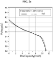
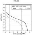
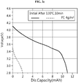
- lithium secondary battery having the battery capacity of 11.0 mAh prepared in examples 1 and 2 and comparative example 1 capacity was measured during charging and discharging at the discharge rate of 0.2C at room temperature, and its results were plotted as solid line graphs in FIGS. 2a to 2c . From this, it could be seen that the lithium secondary batteries of examples 1 and 2 and comparative example 1 all achieved the design level of capacity.
- the lithium secondary batteries were kept at 130°C for 30 minutes, and after then, were discharged discharge rate of 0.2C again.
- the lithium secondary batteries of examples 1 and 2 showed improved safety even when exposed to high temperature environment because charging and discharging was limited by a desired shut down effect, but it could be seen that the lithium secondary battery of comparative example 1 showed similar charging/discharging behaviors to those of room temperature (solid line graph) at high temperature (dashed line graph) of FIG. 2a , and safety of the lithium secondary battery was not improved.
Landscapes
- Chemical & Material Sciences (AREA)
- Chemical Kinetics & Catalysis (AREA)
- Electrochemistry (AREA)
- General Chemical & Material Sciences (AREA)
- Engineering & Computer Science (AREA)
- Manufacturing & Machinery (AREA)
- Inorganic Chemistry (AREA)
- Condensed Matter Physics & Semiconductors (AREA)
- Physics & Mathematics (AREA)
- General Physics & Mathematics (AREA)
- Materials Engineering (AREA)
- Dispersion Chemistry (AREA)
- Ceramic Engineering (AREA)
- Battery Electrode And Active Subsutance (AREA)
- Secondary Cells (AREA)
- Electric Double-Layer Capacitors Or The Like (AREA)
- Cell Separators (AREA)
Claims (10)
- Ensemble électrode comprenant :une électrode positive composée d'un collecteur de courant d'électrode positive, d'une couche de matériau actif d'électrode positive et d'une couche de revêtement poreux, empilés dans un ordre séquentiel ; etune électrode négative composée d'un collecteur de courant d'électrode négative, d'une couche de matériau actif d'électrode négative et d'une couche de revêtement poreux, empilés dans un ordre séquentiel,caractérisé en ce que soit la couche de revêtement poreux à l'électrode positive, soit la couche de revêtement poreux à l'électrode négative est une couche de revêtement poreux organique, et l'autre est une couche de revêtement poreux inorganique, etdans lequel la couche de revêtement poreux organique est exempte de particules inorganiques et inclut des particules sphériques formées à partir d'au moins un élément sélectionné dans le groupe constitué de polyéthylène haute densité, polyéthylène faible densité, polyéthylène faible densité linéaire, polypropylène, polypropylène hautement cristallin, copolymère de polyéthylène-propylène, copolymère de polyéthylène-butylène, copolymère de polyéthylène-hexène, copolymère de polyéthylène-octène, copolymère de polystyrène-butylène-styrène, copolymère de polystyrène-éthylène-butylène-styrène, polystyrène, oxyde de polyphénylène, polysulfone, polycarbonate, polyester, polyamide, polyuréthane, polyacrylate, chlorure de polyvinylidène, polysiloxane, ionomère de polyoléfine, pentène polyméthylique, oligocyclopentadiène hydrogéné (HOCP), et leurs dérivés,la couche de revêtement poreux organique et la couche de revêtement poreux inorganique sont face l'une à l'autre.
- Ensemble électrode selon la revendication 1, dans lequel la couche de revêtement poreux organique est revêtue dans une quantité comprise entre 0,1 et 7 g/m2 sur une surface de la couche de matériau actif d'électrode.
- Ensemble électrode selon la revendication 1, dans lequel la couche de revêtement poreux inorganique inclut des particules inorganiques ayant une constante diélectrique égale ou supérieure à 5, les particules inorganiques ayant une capacité de transporter des ions de lithium, ou leurs mélanges.
- Ensemble électrode selon la revendication 3, dans lequel les particules inorganiques ayant une constante diélectrique égale ou supérieure à 5 sont BaTiO3, Pb(Zr,Ti)O3 (PZT), Pb1-xLaxZr1-yTiyO3 (PLZT), PB(Mg1/3Nb2/3O3 - PbTiO3(PMN-PT), hafnia (HfO2), SrTiO3, SnO2, CeO2, MgO, NiO, CaO, ZnO, ZrO2, Y2O3, Al2O3, TiO2, ou leurs mélanges.
- Ensemble électrode selon la revendication 3, dans lequel les particules inorganiques ayant une capacité à transporter des ions de lithium sont
phosphate de lithium (Li3PO4),
phosphate de lithium titane (LixTiv(PO4)3, 0 < x < 2, 0 < y < 3),
phosphate de lithium aluminium titane (LixAlvTiz(PO4)3, 0 < x < 2, 0 < y < 1, 0 < z < 3),
verre à base de (LiAlTiP)xOv (0 < x < 4, 0 < y < 13),
titanate de lithium lanthane (LixLavTiO3, 0 < x < 2, 0 < y < 3),
thiophosphate de lithium germanium (LixGevPzSw, 0 < x < 4, 0 < y < 1, 0 < z < 1, 0 < w < 5),
nitrure de lithium (LixNy, 0 < x < 4, 0 < y < 2),
verre à base de SiS2 (LixSiySz, 0 < x < 3, 0 < y < 3, 0 < z < 4),
verre à base de P2S5 (LixPvSz, 0 < x < 3, 0 < y < 3, 0 < z < 7),
ou leurs mélanges. - Ensemble électrode selon la revendication 1, dans lequel la couche de revêtement poreux inorganique est revêtue dans une quantité comprise entre 1 et 30 g/m2, sur une surface de la couche de matériau actif d'électrode.
- Dispositif électrochimique comprenant l'ensemble électrode défini dans l'une quelconque des revendications 1 à 6,
- Dispositif électrochimique selon la revendication 7, dans lequel le dispositif électrochimique est une batterie rechargeable au lithium.
- Procédé de fabrication d'un ensemble électrode selon la revendication 1, consistant à :(a) appliquer une suspension d'électrode mélangée à un collecteur de courant pour fabriquer une électrode ;(b) préparer une suspension incluant des particules inorganiques, et enduire la suspension sur une surface d'une couche de matériau actif d'électrode de l'électrode et sécher pour former une couche de revêtement poreux inorganique ;(c) appliquer une suspension d'électrode mélangée à un collecteur de courant pour fabriquer une autre électrode ;(d) préparer une suspension incluant des particules organiques, exempte de particules inorganiques, et qui inclut des particules sphériques, et enduire la suspension sur une surface d'une couche de matériau actif d'électrode de l'autre électrode et sécher pour former une couche de revêtement poreux organique ; ete) empiler les électrodes de telle sorte que la couche de revêtement poreux inorganique et la couche de revêtement poreux organique sont face l'une à l'autre.
- Procédé de fabrication d'un ensemble électrode selon la revendication 9, dans lequel après l'étape (b) ou (d) et avant l'étape (e), un processus de stratification est effectué à une température comprise entre 30 et 150°C et à une pression comprise entre 98 000 et 490 000 N/cm2 pour une liaison entre la couche de revêtement poreux et l'électrode.
Priority Applications (1)
| Application Number | Priority Date | Filing Date | Title |
|---|---|---|---|
| PL15868161T PL3190652T3 (pl) | 2014-12-08 | 2015-12-08 | Zespół elektrod o ulepszonym bezpieczeństwie, sposób jego wytwarzania i element elektrochemiczny obejmujący zespół elektrod |
Applications Claiming Priority (2)
| Application Number | Priority Date | Filing Date | Title |
|---|---|---|---|
| KR20140175285 | 2014-12-08 | ||
| PCT/KR2015/013378 WO2016093589A1 (fr) | 2014-12-08 | 2015-12-08 | Ensemble d'électrodes à sécurité améliorée, son procédé de fabrication et élément électrochimique comprenant l'ensemble d'électrodes |
Publications (3)
| Publication Number | Publication Date |
|---|---|
| EP3190652A1 EP3190652A1 (fr) | 2017-07-12 |
| EP3190652A4 EP3190652A4 (fr) | 2017-09-13 |
| EP3190652B1 true EP3190652B1 (fr) | 2019-08-14 |
Family
ID=56107703
Family Applications (1)
| Application Number | Title | Priority Date | Filing Date |
|---|---|---|---|
| EP15868161.9A Active EP3190652B1 (fr) | 2014-12-08 | 2015-12-08 | Ensemble d'électrodes à sécurité améliorée, son procédé de fabrication et élément électrochimique comprenant l'ensemble d'électrodes |
Country Status (7)
| Country | Link |
|---|---|
| US (1) | US10629913B2 (fr) |
| EP (1) | EP3190652B1 (fr) |
| JP (1) | JP6461328B2 (fr) |
| KR (1) | KR101734328B1 (fr) |
| CN (1) | CN107004808B (fr) |
| PL (1) | PL3190652T3 (fr) |
| WO (1) | WO2016093589A1 (fr) |
Families Citing this family (26)
| Publication number | Priority date | Publication date | Assignee | Title |
|---|---|---|---|---|
| CN107623098A (zh) * | 2016-07-15 | 2018-01-23 | 万向二三股份公司 | 一种锂离子电池安全涂层、其应用及锂离子电池 |
| DE102016008918B4 (de) * | 2016-07-21 | 2023-08-03 | Mercedes-Benz Group AG | Elektrode, elektrochemischer Energiespeicher mit einer Elektrode und Verfahren zur Herstellung einer Elektrode |
| CN106848383A (zh) * | 2017-03-06 | 2017-06-13 | 曙鹏科技(深圳)有限公司 | 一种高安全性的锂离子电池及其制备方法 |
| CN107424849B (zh) * | 2017-06-30 | 2019-05-03 | 南京邮电大学 | 一种以ps微球为电极间隔材料制备透明超级电容器的方法 |
| JP6783735B2 (ja) * | 2017-09-19 | 2020-11-11 | 株式会社東芝 | リチウムイオン二次電池用の電極群、二次電池、電池パック及び車両 |
| CN108023125A (zh) * | 2017-11-27 | 2018-05-11 | 覃晓捷 | 一种提高锂离子电池电化学性能的制备方法 |
| CN107732292A (zh) * | 2017-11-28 | 2018-02-23 | 覃晓捷 | 一种锂离子电池及其提高电化学性能的处理方法 |
| KR102270120B1 (ko) * | 2017-12-01 | 2021-06-28 | 주식회사 엘지에너지솔루션 | 전극 및 전극조립체 |
| WO2019108017A1 (fr) | 2017-12-01 | 2019-06-06 | 주식회사 엘지화학 | Électrode et ensemble d'électrodes |
| CN110165292B (zh) * | 2018-02-13 | 2021-02-12 | 北京卫蓝新能源科技有限公司 | 一种改性nasicon型固态电解质片及其制备方法 |
| WO2019183865A1 (fr) * | 2018-03-29 | 2019-10-03 | 深圳前海优容科技有限公司 | Élément de batterie et son procédé de fabrication, batterie et dispositif électronique |
| KR102500240B1 (ko) * | 2018-06-29 | 2023-02-16 | 주식회사 엘지에너지솔루션 | 전극 조립체 제조방법 |
| US10784505B2 (en) | 2018-08-09 | 2020-09-22 | Toyota Motor Engineering & Manufacturing North America, Inc. | Air stable lithium sulfide cathode compositions, methods for producing them, and solid-state lithium batteries incorporating the same |
| KR102279515B1 (ko) | 2018-09-03 | 2021-07-20 | 삼성에스디아이 주식회사 | 리튬 이차 전지용 분리막 및 이를 포함하는 리튬 이차 전지 |
| CN109461869B (zh) * | 2018-11-04 | 2021-10-15 | 苏州华骞时代新能源科技有限公司 | 一种复合隔膜及其制备方法 |
| DE102018221983B4 (de) * | 2018-12-17 | 2023-07-27 | Vitesco Technologies Germany Gmbh | Verfahren zur Herstellung einer Elektrolytschicht auf einer Kathodenschicht und diese enthaltende Batteriezelle |
| CN111326736B (zh) * | 2018-12-17 | 2021-05-28 | 宁德时代新能源科技股份有限公司 | 锂金属电池 |
| EP3951917A4 (fr) * | 2019-03-26 | 2022-06-22 | Panasonic Intellectual Property Management Co., Ltd. | Batterie rechargeable |
| CN109802083B (zh) * | 2019-03-29 | 2022-02-01 | 宁德新能源科技有限公司 | 电化学装置 |
| CN112993220B (zh) * | 2019-12-17 | 2022-08-19 | 山东海科创新研究院有限公司 | 一种用于锂离子电池正负极片的功能涂层浆料及其制备方法、锂离子电池 |
| EP4020650A4 (fr) * | 2020-03-04 | 2023-02-15 | Ningde Amperex Technology Limited | Dispositif électrochimique et dispositif électronique le comprenant |
| EP4131539A4 (fr) * | 2020-03-27 | 2023-07-19 | Amperex Technology Limited | Dispositif électrochimique |
| CN111564661A (zh) * | 2020-06-24 | 2020-08-21 | 天能帅福得能源股份有限公司 | 一种高安全性的锂离子电池 |
| CN112002939B (zh) * | 2020-08-31 | 2021-10-15 | 成都新柯力化工科技有限公司 | 一种锂电池固体电解质的清洁制备方法 |
| CN112331873A (zh) * | 2020-11-11 | 2021-02-05 | 河北零点新能源科技有限公司 | 一种改善锂电池温升的制作方法 |
| WO2024043660A1 (fr) * | 2022-08-22 | 2024-02-29 | 주식회사 엘지화학 | Électrode pour batterie secondaire au lithium et batterie secondaire au lithium |
Family Cites Families (24)
| Publication number | Priority date | Publication date | Assignee | Title |
|---|---|---|---|---|
| ATE310321T1 (de) * | 1995-06-28 | 2005-12-15 | Ube Industries | Nichtwässrige sekundärbatterie |
| JP2001135359A (ja) * | 1999-08-24 | 2001-05-18 | Japan Storage Battery Co Ltd | 非水電解質電池 |
| KR100467705B1 (ko) * | 2002-11-02 | 2005-01-24 | 삼성에스디아이 주식회사 | 무기 보호막을 갖는 세퍼레이타 및 이를 채용한 리튬 전지 |
| TWI258238B (en) | 2003-11-05 | 2006-07-11 | Lg Chemical Ltd | Functional polymer film-coated electrode and electrochemical device using the same |
| KR100666821B1 (ko) * | 2004-02-07 | 2007-01-09 | 주식회사 엘지화학 | 유/무기 복합 다공성 코팅층이 형성된 전극 및 이를포함하는 전기 화학 소자 |
| KR100790280B1 (ko) * | 2004-03-30 | 2008-01-02 | 마쯔시다덴기산교 가부시키가이샤 | 비수전해액 2차 전지 |
| WO2005112150A1 (fr) | 2004-05-14 | 2005-11-24 | Matsushita Electric Industrial Co., Ltd. | Batterie secondaire ionique au lithium et procede de fabrication de ladite batterie |
| JP5077864B2 (ja) | 2004-05-14 | 2012-11-21 | パナソニック株式会社 | リチウムイオン二次電池とその製造法 |
| JP2006100051A (ja) | 2004-09-29 | 2006-04-13 | Hitachi Maxell Ltd | 非水二次電池およびその製造方法 |
| KR100791791B1 (ko) | 2006-03-10 | 2008-01-04 | 주식회사 엘지화학 | 다공성 활성층이 코팅된 전극, 그 제조방법 및 이를 구비한전기화학소자 |
| JP5394610B2 (ja) * | 2007-02-20 | 2014-01-22 | パナソニック株式会社 | 非水電解質二次電池 |
| KR101002161B1 (ko) | 2007-11-29 | 2010-12-17 | 주식회사 엘지화학 | 다공성 코팅층이 형성된 세퍼레이터, 그 제조방법 및 이를 구비한 전기화학소자 |
| KR101040482B1 (ko) | 2008-03-04 | 2011-06-09 | 주식회사 엘지화학 | 다공성 코팅층이 코팅된 세퍼레이터 및 이를 구비한 전기화학소자 |
| JP5689800B2 (ja) * | 2008-09-03 | 2015-03-25 | エルジー・ケム・リミテッド | 多孔性コーティング層を備えたセパレータ及びこれを備えた電気化学素子 |
| JP5742512B2 (ja) | 2010-06-28 | 2015-07-01 | 株式会社村田製作所 | 蓄電デバイスの製造方法 |
| CN103238249B (zh) | 2010-11-30 | 2016-09-21 | 株式会社Lg化学 | 锂二次电池 |
| US20120231321A1 (en) | 2011-03-11 | 2012-09-13 | GM Global Technology Operations LLC | Integral bi-layer separator-electrode construction for lithium-ion batteries |
| KR101453037B1 (ko) | 2011-03-23 | 2014-10-21 | 주식회사 엘지화학 | 전극조립체 및 이의 제조방법 |
| CN103155216A (zh) * | 2011-10-03 | 2013-06-12 | 日立麦克赛尔株式会社 | 耐热性多孔质膜、非水电池用隔膜以及非水电池 |
| JP5659996B2 (ja) | 2011-10-06 | 2015-01-28 | トヨタ自動車株式会社 | リチウムイオン二次電池の製造方法 |
| DE112011105969T5 (de) * | 2011-12-19 | 2014-09-25 | Toyota Jidosha Kabushiki Kaisha | Lithiumsekundärbatterie |
| KR101683212B1 (ko) | 2012-02-07 | 2016-12-06 | 삼성에스디아이 주식회사 | 리튬 이차 전지의 제조 방법 |
| KR101454830B1 (ko) * | 2012-09-24 | 2014-10-28 | 주식회사 엘지화학 | 리튬 이차전지용 세퍼레이터의 제조방법, 그 방법에 의해 제조된 세퍼레이터, 및 이를 포함하는 리튬 이차전지 |
| CA2878079C (fr) * | 2012-11-02 | 2022-07-19 | Arkema Inc. | Assemblages de separateurs d'electrodes integres fluoropolymere pour desbatteries au lithium-ion |
-
2015
- 2015-12-08 US US15/517,690 patent/US10629913B2/en active Active
- 2015-12-08 PL PL15868161T patent/PL3190652T3/pl unknown
- 2015-12-08 WO PCT/KR2015/013378 patent/WO2016093589A1/fr active Application Filing
- 2015-12-08 EP EP15868161.9A patent/EP3190652B1/fr active Active
- 2015-12-08 KR KR1020150174286A patent/KR101734328B1/ko active IP Right Grant
- 2015-12-08 CN CN201580058072.4A patent/CN107004808B/zh active Active
- 2015-12-08 JP JP2017519476A patent/JP6461328B2/ja active Active
Non-Patent Citations (1)
| Title |
|---|
| None * |
Also Published As
| Publication number | Publication date |
|---|---|
| US10629913B2 (en) | 2020-04-21 |
| EP3190652A4 (fr) | 2017-09-13 |
| KR20160069493A (ko) | 2016-06-16 |
| KR101734328B1 (ko) | 2017-05-11 |
| EP3190652A1 (fr) | 2017-07-12 |
| JP2018503933A (ja) | 2018-02-08 |
| CN107004808B (zh) | 2019-11-12 |
| US20170309915A1 (en) | 2017-10-26 |
| WO2016093589A1 (fr) | 2016-06-16 |
| JP6461328B2 (ja) | 2019-01-30 |
| CN107004808A (zh) | 2017-08-01 |
| PL3190652T3 (pl) | 2020-02-28 |
Similar Documents
| Publication | Publication Date | Title |
|---|---|---|
| EP3190652B1 (fr) | Ensemble d'électrodes à sécurité améliorée, son procédé de fabrication et élément électrochimique comprenant l'ensemble d'électrodes | |
| JP5883762B2 (ja) | 有機無機複合多孔性高分子フィルム | |
| KR101040482B1 (ko) | 다공성 코팅층이 코팅된 세퍼레이터 및 이를 구비한 전기화학소자 | |
| US9368777B2 (en) | Electrochemical device with improved cycle characteristics | |
| KR100983438B1 (ko) | 다공성 코팅층이 형성된 세퍼레이터 및 이를 구비한전기화학소자 | |
| EP2750219A1 (fr) | Procédé de fabrication d'un séparateur, séparateur formé par ledit procédé et dispositif électrochimique présentant ledit séparateur | |
| KR20060041649A (ko) | 유/무기 복합 다공성 코팅층이 형성된 전극 및 이를포함하는 전기 화학 소자 | |
| KR100999309B1 (ko) | 다공성 코팅층이 형성된 세퍼레이터 및 이를 구비한전기화학소자 | |
| KR101596491B1 (ko) | 사이클 특성이 개선된 전기화학소자 | |
| KR20220009917A (ko) | 전지 셀 및 이의 제조방법 | |
| JP5902692B6 (ja) | サイクル特性が改善した電気化学素子 |
Legal Events
| Date | Code | Title | Description |
|---|---|---|---|
| STAA | Information on the status of an ep patent application or granted ep patent |
Free format text: STATUS: THE INTERNATIONAL PUBLICATION HAS BEEN MADE |
|
| PUAI | Public reference made under article 153(3) epc to a published international application that has entered the european phase |
Free format text: ORIGINAL CODE: 0009012 |
|
| STAA | Information on the status of an ep patent application or granted ep patent |
Free format text: STATUS: REQUEST FOR EXAMINATION WAS MADE |
|
| 17P | Request for examination filed |
Effective date: 20170404 |
|
| AK | Designated contracting states |
Kind code of ref document: A1 Designated state(s): AL AT BE BG CH CY CZ DE DK EE ES FI FR GB GR HR HU IE IS IT LI LT LU LV MC MK MT NL NO PL PT RO RS SE SI SK SM TR |
|
| AX | Request for extension of the european patent |
Extension state: BA ME |
|
| A4 | Supplementary search report drawn up and despatched |
Effective date: 20170816 |
|
| RIC1 | Information provided on ipc code assigned before grant |
Ipc: H01M 10/052 20100101ALI20170809BHEP Ipc: H01M 2/16 20060101ALI20170809BHEP Ipc: H01M 4/13 20100101ALI20170809BHEP Ipc: H01M 4/04 20060101ALI20170809BHEP Ipc: H01M 4/139 20100101ALI20170809BHEP Ipc: H01M 10/0562 20100101ALI20170809BHEP Ipc: H01M 10/0565 20100101ALI20170809BHEP Ipc: H01M 10/42 20060101ALI20170809BHEP Ipc: H01M 10/058 20100101ALI20170809BHEP Ipc: H01M 10/04 20060101AFI20170809BHEP |
|
| STAA | Information on the status of an ep patent application or granted ep patent |
Free format text: STATUS: EXAMINATION IS IN PROGRESS |
|
| DAV | Request for validation of the european patent (deleted) | ||
| DAX | Request for extension of the european patent (deleted) | ||
| 17Q | First examination report despatched |
Effective date: 20180312 |
|
| REG | Reference to a national code |
Ref country code: DE Ref legal event code: R079 Ref document number: 602015036057 Country of ref document: DE Free format text: PREVIOUS MAIN CLASS: H01M0010040000 Ipc: H01M0004620000 |
|
| GRAP | Despatch of communication of intention to grant a patent |
Free format text: ORIGINAL CODE: EPIDOSNIGR1 |
|
| STAA | Information on the status of an ep patent application or granted ep patent |
Free format text: STATUS: GRANT OF PATENT IS INTENDED |
|
| GRAJ | Information related to disapproval of communication of intention to grant by the applicant or resumption of examination proceedings by the epo deleted |
Free format text: ORIGINAL CODE: EPIDOSDIGR1 |
|
| RIC1 | Information provided on ipc code assigned before grant |
Ipc: H01M 4/139 20100101ALI20190430BHEP Ipc: H01M 4/04 20060101ALI20190430BHEP Ipc: H01M 10/058 20100101ALI20190430BHEP Ipc: H01M 4/62 20060101AFI20190430BHEP Ipc: H01M 10/0562 20100101ALI20190430BHEP Ipc: H01M 10/0565 20100101ALI20190430BHEP Ipc: H01M 10/0525 20100101ALI20190430BHEP Ipc: H01M 4/13 20100101ALI20190430BHEP Ipc: H01M 10/052 20100101ALI20190430BHEP Ipc: H01M 2/16 20060101ALI20190430BHEP Ipc: H01M 10/42 20060101ALI20190430BHEP Ipc: H01M 10/04 20060101ALI20190430BHEP |
|
| GRAP | Despatch of communication of intention to grant a patent |
Free format text: ORIGINAL CODE: EPIDOSNIGR1 |
|
| INTG | Intention to grant announced |
Effective date: 20190520 |
|
| INTG | Intention to grant announced |
Effective date: 20190607 |
|
| GRAS | Grant fee paid |
Free format text: ORIGINAL CODE: EPIDOSNIGR3 |
|
| GRAA | (expected) grant |
Free format text: ORIGINAL CODE: 0009210 |
|
| STAA | Information on the status of an ep patent application or granted ep patent |
Free format text: STATUS: THE PATENT HAS BEEN GRANTED |
|
| AK | Designated contracting states |
Kind code of ref document: B1 Designated state(s): AL AT BE BG CH CY CZ DE DK EE ES FI FR GB GR HR HU IE IS IT LI LT LU LV MC MK MT NL NO PL PT RO RS SE SI SK SM TR |
|
| REG | Reference to a national code |
Ref country code: GB Ref legal event code: FG4D |
|
| REG | Reference to a national code |
Ref country code: CH Ref legal event code: EP Ref country code: AT Ref legal event code: REF Ref document number: 1168091 Country of ref document: AT Kind code of ref document: T Effective date: 20190815 |
|
| REG | Reference to a national code |
Ref country code: IE Ref legal event code: FG4D |
|
| REG | Reference to a national code |
Ref country code: DE Ref legal event code: R096 Ref document number: 602015036057 Country of ref document: DE |
|
| REG | Reference to a national code |
Ref country code: NL Ref legal event code: MP Effective date: 20190814 |
|
| REG | Reference to a national code |
Ref country code: LT Ref legal event code: MG4D |
|
| PG25 | Lapsed in a contracting state [announced via postgrant information from national office to epo] |
Ref country code: FI Free format text: LAPSE BECAUSE OF FAILURE TO SUBMIT A TRANSLATION OF THE DESCRIPTION OR TO PAY THE FEE WITHIN THE PRESCRIBED TIME-LIMIT Effective date: 20190814 Ref country code: BG Free format text: LAPSE BECAUSE OF FAILURE TO SUBMIT A TRANSLATION OF THE DESCRIPTION OR TO PAY THE FEE WITHIN THE PRESCRIBED TIME-LIMIT Effective date: 20191114 Ref country code: SE Free format text: LAPSE BECAUSE OF FAILURE TO SUBMIT A TRANSLATION OF THE DESCRIPTION OR TO PAY THE FEE WITHIN THE PRESCRIBED TIME-LIMIT Effective date: 20190814 Ref country code: NO Free format text: LAPSE BECAUSE OF FAILURE TO SUBMIT A TRANSLATION OF THE DESCRIPTION OR TO PAY THE FEE WITHIN THE PRESCRIBED TIME-LIMIT Effective date: 20191114 Ref country code: NL Free format text: LAPSE BECAUSE OF FAILURE TO SUBMIT A TRANSLATION OF THE DESCRIPTION OR TO PAY THE FEE WITHIN THE PRESCRIBED TIME-LIMIT Effective date: 20190814 Ref country code: LT Free format text: LAPSE BECAUSE OF FAILURE TO SUBMIT A TRANSLATION OF THE DESCRIPTION OR TO PAY THE FEE WITHIN THE PRESCRIBED TIME-LIMIT Effective date: 20190814 Ref country code: PT Free format text: LAPSE BECAUSE OF FAILURE TO SUBMIT A TRANSLATION OF THE DESCRIPTION OR TO PAY THE FEE WITHIN THE PRESCRIBED TIME-LIMIT Effective date: 20191216 Ref country code: HR Free format text: LAPSE BECAUSE OF FAILURE TO SUBMIT A TRANSLATION OF THE DESCRIPTION OR TO PAY THE FEE WITHIN THE PRESCRIBED TIME-LIMIT Effective date: 20190814 |
|
| REG | Reference to a national code |
Ref country code: AT Ref legal event code: MK05 Ref document number: 1168091 Country of ref document: AT Kind code of ref document: T Effective date: 20190814 |
|
| PG25 | Lapsed in a contracting state [announced via postgrant information from national office to epo] |
Ref country code: IS Free format text: LAPSE BECAUSE OF FAILURE TO SUBMIT A TRANSLATION OF THE DESCRIPTION OR TO PAY THE FEE WITHIN THE PRESCRIBED TIME-LIMIT Effective date: 20191214 Ref country code: RS Free format text: LAPSE BECAUSE OF FAILURE TO SUBMIT A TRANSLATION OF THE DESCRIPTION OR TO PAY THE FEE WITHIN THE PRESCRIBED TIME-LIMIT Effective date: 20190814 Ref country code: GR Free format text: LAPSE BECAUSE OF FAILURE TO SUBMIT A TRANSLATION OF THE DESCRIPTION OR TO PAY THE FEE WITHIN THE PRESCRIBED TIME-LIMIT Effective date: 20191115 Ref country code: ES Free format text: LAPSE BECAUSE OF FAILURE TO SUBMIT A TRANSLATION OF THE DESCRIPTION OR TO PAY THE FEE WITHIN THE PRESCRIBED TIME-LIMIT Effective date: 20190814 Ref country code: AL Free format text: LAPSE BECAUSE OF FAILURE TO SUBMIT A TRANSLATION OF THE DESCRIPTION OR TO PAY THE FEE WITHIN THE PRESCRIBED TIME-LIMIT Effective date: 20190814 Ref country code: LV Free format text: LAPSE BECAUSE OF FAILURE TO SUBMIT A TRANSLATION OF THE DESCRIPTION OR TO PAY THE FEE WITHIN THE PRESCRIBED TIME-LIMIT Effective date: 20190814 |
|
| PG25 | Lapsed in a contracting state [announced via postgrant information from national office to epo] |
Ref country code: TR Free format text: LAPSE BECAUSE OF FAILURE TO SUBMIT A TRANSLATION OF THE DESCRIPTION OR TO PAY THE FEE WITHIN THE PRESCRIBED TIME-LIMIT Effective date: 20190814 |
|
| PG25 | Lapsed in a contracting state [announced via postgrant information from national office to epo] |
Ref country code: IT Free format text: LAPSE BECAUSE OF FAILURE TO SUBMIT A TRANSLATION OF THE DESCRIPTION OR TO PAY THE FEE WITHIN THE PRESCRIBED TIME-LIMIT Effective date: 20190814 Ref country code: EE Free format text: LAPSE BECAUSE OF FAILURE TO SUBMIT A TRANSLATION OF THE DESCRIPTION OR TO PAY THE FEE WITHIN THE PRESCRIBED TIME-LIMIT Effective date: 20190814 Ref country code: DK Free format text: LAPSE BECAUSE OF FAILURE TO SUBMIT A TRANSLATION OF THE DESCRIPTION OR TO PAY THE FEE WITHIN THE PRESCRIBED TIME-LIMIT Effective date: 20190814 Ref country code: AT Free format text: LAPSE BECAUSE OF FAILURE TO SUBMIT A TRANSLATION OF THE DESCRIPTION OR TO PAY THE FEE WITHIN THE PRESCRIBED TIME-LIMIT Effective date: 20190814 Ref country code: RO Free format text: LAPSE BECAUSE OF FAILURE TO SUBMIT A TRANSLATION OF THE DESCRIPTION OR TO PAY THE FEE WITHIN THE PRESCRIBED TIME-LIMIT Effective date: 20190814 |
|
| PG25 | Lapsed in a contracting state [announced via postgrant information from national office to epo] |
Ref country code: SK Free format text: LAPSE BECAUSE OF FAILURE TO SUBMIT A TRANSLATION OF THE DESCRIPTION OR TO PAY THE FEE WITHIN THE PRESCRIBED TIME-LIMIT Effective date: 20190814 Ref country code: CZ Free format text: LAPSE BECAUSE OF FAILURE TO SUBMIT A TRANSLATION OF THE DESCRIPTION OR TO PAY THE FEE WITHIN THE PRESCRIBED TIME-LIMIT Effective date: 20190814 Ref country code: SM Free format text: LAPSE BECAUSE OF FAILURE TO SUBMIT A TRANSLATION OF THE DESCRIPTION OR TO PAY THE FEE WITHIN THE PRESCRIBED TIME-LIMIT Effective date: 20190814 Ref country code: IS Free format text: LAPSE BECAUSE OF FAILURE TO SUBMIT A TRANSLATION OF THE DESCRIPTION OR TO PAY THE FEE WITHIN THE PRESCRIBED TIME-LIMIT Effective date: 20200224 |
|
| REG | Reference to a national code |
Ref country code: DE Ref legal event code: R097 Ref document number: 602015036057 Country of ref document: DE |
|
| PLBE | No opposition filed within time limit |
Free format text: ORIGINAL CODE: 0009261 |
|
| STAA | Information on the status of an ep patent application or granted ep patent |
Free format text: STATUS: NO OPPOSITION FILED WITHIN TIME LIMIT |
|
| PG2D | Information on lapse in contracting state deleted |
Ref country code: IS |
|
| REG | Reference to a national code |
Ref country code: CH Ref legal event code: PL |
|
| 26N | No opposition filed |
Effective date: 20200603 |
|
| REG | Reference to a national code |
Ref country code: BE Ref legal event code: MM Effective date: 20191231 |
|
| PG25 | Lapsed in a contracting state [announced via postgrant information from national office to epo] |
Ref country code: SI Free format text: LAPSE BECAUSE OF FAILURE TO SUBMIT A TRANSLATION OF THE DESCRIPTION OR TO PAY THE FEE WITHIN THE PRESCRIBED TIME-LIMIT Effective date: 20190814 Ref country code: MC Free format text: LAPSE BECAUSE OF FAILURE TO SUBMIT A TRANSLATION OF THE DESCRIPTION OR TO PAY THE FEE WITHIN THE PRESCRIBED TIME-LIMIT Effective date: 20190814 |
|
| PG25 | Lapsed in a contracting state [announced via postgrant information from national office to epo] |
Ref country code: LU Free format text: LAPSE BECAUSE OF NON-PAYMENT OF DUE FEES Effective date: 20191208 Ref country code: IE Free format text: LAPSE BECAUSE OF NON-PAYMENT OF DUE FEES Effective date: 20191208 |
|
| PG25 | Lapsed in a contracting state [announced via postgrant information from national office to epo] |
Ref country code: BE Free format text: LAPSE BECAUSE OF NON-PAYMENT OF DUE FEES Effective date: 20191231 Ref country code: CH Free format text: LAPSE BECAUSE OF NON-PAYMENT OF DUE FEES Effective date: 20191231 Ref country code: LI Free format text: LAPSE BECAUSE OF NON-PAYMENT OF DUE FEES Effective date: 20191231 |
|
| PG25 | Lapsed in a contracting state [announced via postgrant information from national office to epo] |
Ref country code: CY Free format text: LAPSE BECAUSE OF FAILURE TO SUBMIT A TRANSLATION OF THE DESCRIPTION OR TO PAY THE FEE WITHIN THE PRESCRIBED TIME-LIMIT Effective date: 20190814 |
|
| PG25 | Lapsed in a contracting state [announced via postgrant information from national office to epo] |
Ref country code: HU Free format text: LAPSE BECAUSE OF FAILURE TO SUBMIT A TRANSLATION OF THE DESCRIPTION OR TO PAY THE FEE WITHIN THE PRESCRIBED TIME-LIMIT; INVALID AB INITIO Effective date: 20151208 Ref country code: MT Free format text: LAPSE BECAUSE OF FAILURE TO SUBMIT A TRANSLATION OF THE DESCRIPTION OR TO PAY THE FEE WITHIN THE PRESCRIBED TIME-LIMIT Effective date: 20190814 |
|
| PG25 | Lapsed in a contracting state [announced via postgrant information from national office to epo] |
Ref country code: MK Free format text: LAPSE BECAUSE OF FAILURE TO SUBMIT A TRANSLATION OF THE DESCRIPTION OR TO PAY THE FEE WITHIN THE PRESCRIBED TIME-LIMIT Effective date: 20190814 |
|
| P01 | Opt-out of the competence of the unified patent court (upc) registered |
Effective date: 20230323 |
|
| REG | Reference to a national code |
Ref country code: DE Ref legal event code: R081 Ref document number: 602015036057 Country of ref document: DE Owner name: LG ENERGY SOLUTION, LTD., KR Free format text: FORMER OWNER: LG CHEM, LTD., SEOUL, KR |
|
| REG | Reference to a national code |
Ref country code: GB Ref legal event code: 732E Free format text: REGISTERED BETWEEN 20230824 AND 20230831 |
|
| PGFP | Annual fee paid to national office [announced via postgrant information from national office to epo] |
Ref country code: GB Payment date: 20231120 Year of fee payment: 9 |
|
| PGFP | Annual fee paid to national office [announced via postgrant information from national office to epo] |
Ref country code: FR Payment date: 20231121 Year of fee payment: 9 Ref country code: DE Payment date: 20231120 Year of fee payment: 9 |
|
| PGFP | Annual fee paid to national office [announced via postgrant information from national office to epo] |
Ref country code: PL Payment date: 20231122 Year of fee payment: 9 |