EP3175301B1 - Cleaning blade, image forming apparatus, and process cartridge - Google Patents
Cleaning blade, image forming apparatus, and process cartridge Download PDFInfo
- Publication number
- EP3175301B1 EP3175301B1 EP15828136.0A EP15828136A EP3175301B1 EP 3175301 B1 EP3175301 B1 EP 3175301B1 EP 15828136 A EP15828136 A EP 15828136A EP 3175301 B1 EP3175301 B1 EP 3175301B1
- Authority
- EP
- European Patent Office
- Prior art keywords
- layer
- cleaning
- edge
- cleaning blade
- line portion
- Prior art date
- Legal status (The legal status is an assumption and is not a legal conclusion. Google has not performed a legal analysis and makes no representation as to the accuracy of the status listed.)
- Active
Links
Images


Classifications
-
- G—PHYSICS
- G03—PHOTOGRAPHY; CINEMATOGRAPHY; ANALOGOUS TECHNIQUES USING WAVES OTHER THAN OPTICAL WAVES; ELECTROGRAPHY; HOLOGRAPHY
- G03G—ELECTROGRAPHY; ELECTROPHOTOGRAPHY; MAGNETOGRAPHY
- G03G21/00—Arrangements not provided for by groups G03G13/00 - G03G19/00, e.g. cleaning, elimination of residual charge
- G03G21/0005—Arrangements not provided for by groups G03G13/00 - G03G19/00, e.g. cleaning, elimination of residual charge for removing solid developer or debris from the electrographic recording medium
- G03G21/0011—Arrangements not provided for by groups G03G13/00 - G03G19/00, e.g. cleaning, elimination of residual charge for removing solid developer or debris from the electrographic recording medium using a blade; Details of cleaning blades, e.g. blade shape, layer forming
- G03G21/0017—Details relating to the internal structure or chemical composition of the blades
-
- G—PHYSICS
- G03—PHOTOGRAPHY; CINEMATOGRAPHY; ANALOGOUS TECHNIQUES USING WAVES OTHER THAN OPTICAL WAVES; ELECTROGRAPHY; HOLOGRAPHY
- G03G—ELECTROGRAPHY; ELECTROPHOTOGRAPHY; MAGNETOGRAPHY
- G03G21/00—Arrangements not provided for by groups G03G13/00 - G03G19/00, e.g. cleaning, elimination of residual charge
- G03G21/16—Mechanical means for facilitating the maintenance of the apparatus, e.g. modular arrangements
- G03G21/18—Mechanical means for facilitating the maintenance of the apparatus, e.g. modular arrangements using a processing cartridge, whereby the process cartridge comprises at least two image processing means in a single unit
- G03G21/1803—Arrangements or disposition of the complete process cartridge or parts thereof
- G03G21/1814—Details of parts of process cartridge, e.g. for charging, transfer, cleaning, developing
-
- G—PHYSICS
- G03—PHOTOGRAPHY; CINEMATOGRAPHY; ANALOGOUS TECHNIQUES USING WAVES OTHER THAN OPTICAL WAVES; ELECTROGRAPHY; HOLOGRAPHY
- G03G—ELECTROGRAPHY; ELECTROPHOTOGRAPHY; MAGNETOGRAPHY
- G03G2215/00—Apparatus for electrophotographic processes
- G03G2215/01—Apparatus for electrophotographic processes for producing multicoloured copies
- G03G2215/0103—Plural electrographic recording members
- G03G2215/0119—Linear arrangement adjacent plural transfer points
- G03G2215/0122—Linear arrangement adjacent plural transfer points primary transfer to an intermediate transfer belt
- G03G2215/0125—Linear arrangement adjacent plural transfer points primary transfer to an intermediate transfer belt the linear arrangement being horizontal or slanted
- G03G2215/0132—Linear arrangement adjacent plural transfer points primary transfer to an intermediate transfer belt the linear arrangement being horizontal or slanted vertical medium transport path at the secondary transfer
Definitions
- the present invention relates to a cleaning blade, an electrophotographic image forming apparatus using the cleaning blade, and a process cartridge detachably mounted in the image forming apparatus.
- a cleaning blade serving as a cleaning unit.
- a strip-shaped blade member is used as this cleaning blade, because such a blade member generally has a simple structure and shows excellent cleaning performance.
- a cleaning blade of a blade cleaning system the blade member is supported by a supporting member that is made of a material having high rigidity such as a metal and is fixed to the main frame of a cleaning device, and the edge line portion of the blade member is pressed against the peripheral surface of an image bearer, to remove adhering matter adhering to the image bearer.
- a cleaning blade of a blade cleaning system has a simple structure, is inexpensive, and excels in adhering matter removal performance. Accordingly, such cleaning blades are widely used.
- JP 2014-066767 A discloses a cleaning blade that includes a blade member having a double-layer stack structure formed with elastic members having different characteristics from each other.
- the edge line portion of the edge layer to be brought into contact with an image bearer as the cleaning target member is impregnated with a resin, and the surface of the impregnated edge line portion is further coated with a surface layer having a relatively high degree of hardness, so that the hardness of the edge line portion is increased.
- the hardness of the edge line portion is increased with the impregnated portion and the surface layer. Accordingly, deformation at the edge line portion becomes smaller, and an increase in the contact area can be prevented.
- the contact pressure can be set at a high value, and cleaning performance can be improved.
- the inventors observed the contact pressure that was applied to an image bearer by a blade member over a long period of time. As a result, the inventors discovered that the blade member was permanently deformed into a curved shape, or permanent deformation occurred. The contact state varied from the initial contact state, the contact pressure became lower, and there was a possibility of defective cleaning.
- a blade for an electro-photographic device whose edge and base are constituted by different materials, wherein such blade for an electro-photographic device is characterized in that at least the edge is made of ester polyurethane and the base other than the edge is made of ether polyurethane.
- EP 2 233 979 A1 relates to an image forming apparatus and process cartridge.
- an image forming apparatus including electrophotographic photoreceptor, a charging unit, an electrostatic latent image forming unit, a developing unit, and a residual toner removing unit, the surface protective layer of the electrophotographic photoreceptor having a surface free energy of 10 mN/m to 30 mN/m, the toner in the developing unit includes silica, and the residual toner removing unit including a blade member including a base layer and an edge layer having a type A durometer hardness of from HsA 75 to HsA 90 at 23°C, the hardness of the edge layer being higher than the hardness of the base layer.
- EP 2 749 964 A1 relates to an image forming apparatus, process cartridge, and image forming method.
- An image forming apparatus including: an image bearing member; a charging unit; an exposure unit; a developing unit; a transfer unit; a fixing unit; and a cleaning unit including a cleaning blade
- the charging unit includes a charging roller that is brought into contact with the image bearing member for charging, the charging roller abutting the image bearing member at a pressing force of 10 mN/cm to 1,000 mN/cm
- the cleaning blade includes an elastic member that abuts the surface of the image bearing member to remove a residue attached to the surface of the image bearing member, and wherein an abutment part of the elastic member, which abuts the surface of the image bearing member, includes a cured product of an ultraviolet curable composition containing a (meth)acrylate compound having an alicyclic structure having 6 or more carbon atoms in a molecule.
- JP 2011-203303 A relates to a cleaning blade and image forming apparatus.
- the cleaning blade has a two-layer structure of a cleaning layer directing the side of the photoreceptor and a rear face layer directing the rear side for the photoreceptor.
- the rear face layer and the cleaning layer are integrally molded, and surface roughness Ra of the cleaning layer is 0.12 ⁇ m or less.
- JP 2013-076970 A relates to a cleaning blade, image forming apparatus, and process cartridge.
- the elastic blade is urethane rubber that is 0°C or higher in tan ⁇ peak temperature and 5° or higher in an amount of change in JIS-A hardness from 23°C to 10°C.
- a portion of the elastic blade which portion includes the leading end ridge part is impregnated with UV curable resin with a Martens hardness of 250 to 500 N/mm and an elastic power of 75% or less.
- the surface of the elastic blade including the leading end ridge part is provided with a surface layer with a thickness of 1 ⁇ m or less, the surface layer being harder than the elastic blade.
- JP 2010-139737 A relates to an elastic rubber member made of polyurethane for cleaning blade for electrophotography, and cleaning blade.
- An elastic rubber member made of polyurethane for the cleaning blade for electrophotography comprises an edge layer and a backup layer.
- the edge layer is made of polyurethane using 1,5-naphthalene diisocyanate (NDI) as an isocyanate component and having a hardness of ⁇ 80° (JIS-A)
- the backup layer is made of polyurethane using an isocyanate component other than NDI and having a hardness of ⁇ 80°.
- JP 2010-262158 A relates to an image forming apparatus.
- JP 2010-230705 A relates to a cleaning device and image forming apparatus using the same.
- the cleaning device includes the cleaning blade that comes into contact with the surface of a member to be cleaned to remove a residue remaining on the surface of the member to be cleaned, and that includes multiple layers, wherein the leading end of the cleaning blade shifts in a separating direction from the surface of the member to be cleaned due to a difference in thermal expansion property among the multiple layers when temperature rises.
- JP H 09-127846 A relates to a blade for electrophotographic device.
- the cleaning device includes the cleaning blade that comes into contact with the surface of a member to be cleaned to remove a residue remaining on the surface of the member to be cleaned, and that includes multiple layers, wherein the leading end of the cleaning blade shifts in a separating direction from the surface of the member to be cleaned due to a difference in thermal expansion property among the multiple layers when temperature rises.
- JP 2004-046145 A relates to a blade member.
- the rubber elastic body In the blade member provided with a rubber elastic body 12 which is used by bringing its tip part into contact with a member to be contacted, the rubber elastic body consists of polyurethane rubber and at least the surface of the tip part of the rubber elastic body is coated with surface treatment layers formed by a surface treatment solution containing at least one polymer selected from fluorine group polymers and silicon group polymers and isocyanate component, a surface treatment solution containing carbon black, the above polymer and an isocyanate component.
- JP 2004-233818 A relates to a blade for electronic camera and its manufacturing method. The blade for the electronic camera is supported by a plate type holder and used while the blade is in contact with a contacted member.
- the blade is formed of an elastic body using a urethane rubber composition and a contact part of the blade has (A) a silicon layer which contains silicon being reduced from the surface layer of the contact part toward an inner side and (B) a hardened layer as a surface layer of the silicon layer.
- an excellent effect to improve cleaning performance while reducing permanent deformation of a blade member over time can be achieved.
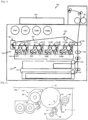
- Fig. 1 is a schematic diagram illustrating the structure of a printer 100 according to this embodiment.
- the printer 100 is designed to form full-color images, and includes an image forming unit 120, an intermediate transfer device 160, and a sheet feeding unit 130.
- the subscripts Y, C, M, and Bk indicate that the components are made for yellow, cyan, magenta, and black, respectively.
- a process cartridge 121Y for yellow toner, a process cartridge 121C for cyan toner, a process cartridge 121M for magenta toner, and a process cartridge 121Bk for black toner are provided.
- These process cartridges 121 (Y, C, M, and Bk) are substantially arranged in a straight horizontal line.
- the process cartridges 121 (Y, C, M, and Bk) are integrally and detachably mounted in the printer 100.
- the intermediate transfer device 160 includes an endless intermediate transfer belt 162 supported by supporting rollers, primary transfer rollers 161 (Y, C, M, and Bk), and a secondary transfer roller 165.
- the intermediate transfer belt 162 extends in the moving direction of the surfaces of the respective drum-shaped photoconductors 10 (Y, C, M, and Bk) serving as latent image bearers that are provided on the respective process cartridges 121 (Y, C, M, and Bk) and performs surface movement.
- the intermediate transfer belt 162 performs surface movement in synchronization with movement of the surfaces of the photoconductors 10 (Y, C, M, and Bk).
- the respective primary transfer rollers 161 (Y, C, M, and Bk) are placed along the inner peripheral surface of the intermediate transfer belt 162, and the surface of the intermediate transfer belt 162 is weakly pressed against the surfaces of the respective photoconductors 10 (Y, C, M, and Bk) by virtue of these primary transfer rollers 161 (Y, C, M, and Bk).
- the structure and operations to form toner images on the respective photoconductors 10 (Y, C, M, and Bk) and transfer the toner images onto the intermediate transfer belt 162 are substantially the same between the respective process cartridges 121 (Y, C, M, and Bk).
- the primary transfer rollers 161 (Y, C, and M) corresponding to the three color process cartridges 121 (Y, C, and M) is equipped with a swinging mechanism (not shown) that causes these three color process cartridges 121 (Y, C, and M) to swing vertically.
- the swinging mechanism operates such that the intermediate transfer belt 162 is not brought into contact with the photoconductors 10 (Y, C, and M) when no color images are formed.
- toner cartridges 159 (Y, C, M, and Bk) corresponding to the respective process cartridges 121 (Y, C, M, and Bk) are aligned substantially in the horizontal direction.
- An exposure device 140 that forms an electrostatic latent image by irradiating the surfaces of charged photoconductors 10 (Y, C, M, and Bk) with laser light is placed below the process cartridges 121 (Y, C, M, and Bk).
- the sheet feeding unit 130 is placed below the exposure device 140.
- the sheet feeding unit 130 includes sheet feeding cassettes 131 that house transfer paper sheets as recording media, and sheet feeding rollers 132.
- a transfer paper sheet is fed to the secondary transfer nip portion between the intermediate transfer belt 162 and the secondary transfer roller 165 via a pair of registration rollers 133 at a predetermined time.
- a fixing device 30 is placed downstream of the secondary transfer nip portion in the transfer paper conveyance direction, and paper ejection rollers and an ejected paper housing unit 135 that houses ejected transfer paper sheets are placed downstream of the fixing device 30 in the transfer paper conveyance direction.
- Fig. 2 is a diagram schematically illustrating an example structure of a process cartridge 121 in the printer 100. Since the structures of the respective process cartridges 121 (Y, C, M, and Bk) are substantially the same, the structure of operation of a process cartridge 121 will be described below while omitting the color-indicating alphabets Y, C, M, and Bk.
- the process cartridge 121 includes a drum-shaped photoconductor 10, a cleaning device 1 placed in the vicinity of the photoconductor 10, a charging unit 40, and a developing unit 50.
- the cleaning device 1 presses the edge line portion 61 of a cleaning blade 5 against the surface of the photoconductor 10.
- the cleaning blade 5 is a strip-shaped elastic member that is long in the direction of the rotational axis of the photoconductor 10.
- the edge line portion 61 is an edge line that extends in a direction perpendicular to the direction of rotation of the photoconductor.
- the charging unit 40 is formed mainly with a charging roller 41 facing the photoconductor 10, and a charging roller cleaner 42 that rotates in contact with the charging roller 41.
- the developing unit (developing device) 50 supplies toner to the surface of the photoconductor 10 and turns an electrostatic latent image into a visible image, and includes a developing roller 51 as a developer bearer that bears a developer (carrier, toner) on its surface.
- the developing unit 50 is formed mainly with this developing roller 51, a stirring screw 52 that conveys the developer housed in a developer container unit while stirring the developer, and a supplying screw 53 that conveys the stirred developer while supplying the stirred developer to the developing roller 51.
- Each of the four process cartridges 121 having the above described structure can be individually detached and exchanged for a new one by a maintenance engineer or a user.
- each of the photoconductor 10, the charging unit 40, the developing unit 50, and the cleaning device 1 can be individually exchanged for a new one.
- Each process cartridge 121 may include a toner waste tank that houses transfer residual toner collected by the cleaning device 1. In this case, if the toner waste tank can be individually detached and exchanged for a new one in each process cartridge 121, a higher level of user-friendliness is achieved.
- the printer 100 receives a printing instruction from an operation panel (not shown) or an external device such as a personal computer.
- each photoconductor 10 is rotated in the moving direction (the rotational direction) indicated by an arrow A in Fig. 2 , and the surface of each photoconductor 10 is uniformly charged with a predetermined polarity by the charging roller 41 of the charging unit 40.
- the exposure device 140 irradiates the charged photoconductors 10 with laser beams for the respective colors that are optically modulated in accordance with input color image data, and thus forms electrostatic latent images for the respective colors on the surfaces of the respective photoconductors 10.
- Developers of the respective colors are supplied to the respective electrostatic latent images from the developing rollers 51 of the developing units 50 for the respective colors, and the electrostatic latent images in the respective colors are developed with the developers for the respective colors and are turned into visible images that are toner images corresponding to the respective colors.
- a transfer voltage of the polarity that is the opposite of the polarity of the toner is then applied to the primary transfer rollers 161, so that a primary transfer field is formed between each photoconductor 10 and each corresponding primary transfer roller 161, with the intermediate transfer belt 162 being interposed.
- the primary transfer rollers 161 weakly presses against the intermediate transfer belt 162, so that primary transfer nips are formed.
- a transfer paper sheet stored in a sheet feeding cassette 131 is fed to the stacked toner image transferred onto the intermediate transfer belt 162 by the primary transfer via the corresponding sheet feeding roller 132, the pair of registration rollers 133, and the like.
- a transfer voltage of the polarity that is opposite to the polarity of the toner is then applied to the secondary transfer roller 165, so that a secondary transfer field is formed between the intermediate transfer belt 162 and the secondary transfer roller 165, with the transfer paper sheet being interposed, and the stacked toner image is transferred onto the transfer paper sheet.
- the transfer paper sheet onto which the stacked toner image has been transferred is sent to the fixing device 30, and fixing is performed with heat and pressure.
- the transfer paper sheet onto which the toner image has been fixed is ejected to the ejected paper housing unit 135 by the paper ejection rollers. Meanwhile, the transfer residual toner remaining on each respective photoconductor 10 after the primary transfer is scraped off and removed with the cleaning blade 5 of each corresponding cleaning device 1.
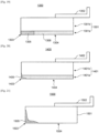
- FIGs. 3A and 3B are schematic diagrams for explaining a conventional cleaning blade.
- a conventional cleaning blade 200 includes a single-layer blade member 201 in which the entire strip-shaped member is formed with a uniform elastic member, and a supporting member 202 that fixes the blade member 201 to the main frame of the cleaning device and is made of a material having high rigidity, such as a metal.
- the blade member 201 is fixed to one end of the supporting member 202 with an adhesive agent or the like, and the other end of the supporting member 202 is cantilevered by the main frame of the cleaning device.
- the blade member 201 removes adhering matter such as transfer residual toner or a toner additive adhering to the surface of the photoconductor.
- the blade member 201 of a cleaning blade is expected to be in contact with the surface of a photoconductor with a high contact pressure so as to achieve excellent removal performance, and the initial contact state is required to be maintained to achieve stable removal performance over a long period of time.
- the single-layer blade member 201 in which the entire blade member is made of a uniform elastic material it is difficult to increase the contact pressure and maintain the initial contact state at the same time. The reasons for this are as follows.
- a single-layer blade member 201 made of an elastic material having a relatively high degree of hardness such as urethane rubber when used, deformation of the edge line portion 203 in contact with an image bearer is small, and increases in the contact area can be restrained. Accordingly, the contact pressure can be made higher, and the cleaning performance can be improved.
- an elastic material having a high degree of hardness generally has a high permanent elongation rate. The blade member 201 is brought into contact with a photoconductor and is bent, with the edge line portion 203 being pressed against the circumferential surface of the photoconductor.
- the blade member 201 made of the elastic material having a high permanent elongation rate is in contact with the photoconductor over a long period of time, the blade member 201 is permanently deformed in a bent shape, or permanent deformation occurs. As a result, the contact state becomes different from the initial contact state, causing defective cleaning.
- another conventional cleaning blade 300 includes: a blade member 301 having a double-layer stack structure formed with an edge layer 301a that is the layer to be in contact with a photoconductor (not shown), and a backup layer 301b stacked on the back surface of the edge layer 301a; and a supporting member 302.
- the edge layer 301a is made of a urethane rubber having a high degree of hardness and a high permanent elongation rate
- the backup layer 301b is made of a urethane rubber having a low degree of hardness and a low permanent elongation rate.
- a single-layer blade member is too rigid to be sufficiently bent when being brought into contact with a photoconductor.
- the cleaning blade cannot adequately cope with unevenness or the like of the surface of the photoconductor, and the cleaning properties are degraded.
- the backup layer 301b has reasonable elasticity, and the edge layer 301a including the edge line portion has an increased degree of hardness. Accordingly, the cleaning blade can appropriately cope with unevenness or the like of the surface of the photoconductor, and excellent cleaning properties can be guaranteed.
- the blade member 301 having such a double-layer structure deformation of the edge line portion 303 in contact with the photoconductor as the member to be cleaned is small, and increase in the contact area can be restrained. Accordingly, the contact pressure can be made higher.
- the degree of hardness of the backup layer 301b not in contact with the photoconductor is low, and the rate of permanent elongation of the backup layer 301b is low. Accordingly, permanent deformation does not occur as easily as that in the above described single-layer blade member 201 having a high degree of hardness, and the initial contact state can be maintained.
- the strength of the elastic material of the edge layer 301a is further increased so as to improve cleaning performance by reducing adhesion of the toner additive to the surface of the photoconductor and to the charging roller, there is a limit to the increase in the strength in the case of the double-layer blade member 301.
- the permanent elongation of the edge layer 301a using an elastic material having a higher degree of strength becomes dominant.
- a decrease in permanent elongation can be corrected by reducing the thickness of the edge layer 301a by a possible amount.
- the strength of the elastic material used as the edge layer 301a cannot be made infinitely higher, and there is a limit to the increase in the strength of the elastic material due to the relationship with permanent deformation. Therefore, with a double-layer blade member, there is a limit to the increase in the strength of the edge line portion for improving cleaning performance by reducing adhesion of the toner additive to the surface of a photoconductor and to the charging roller.
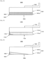
- Figs. 5A and 5B are schematic diagrams for explaining yet another conventional cleaning blade.
- Fig. 6 is a schematic diagram for explaining an impregnation treatment.
- Fig. 7 is a schematic diagram for explaining deformation of the blade member when a cleaning blade is brought into contact with a photoconductor.
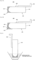
- the conventional cleaning blade 400 shown in Figs. 5A and 5B includes a strip-shaped single-layer blade member 401, and a supporting member 402 that fixes the blade member 401 to the main frame of the cleaning device and is made of a material having high rigidity, such as a metal.
- the single-layer urethane rubber blade member 401 is impregnated with acrylic resin or isocyanate resin, and an impregnated portion 404 is formed, as shown in Fig. 5A .
- coating is performed on part of or all of the impregnated portion 404, and a surface layer 407 is formed, as shown in Fig. 5B .
- the impregnation treatment is performed by immersing the blade member 401 of the cleaning blade 400 in an impregnating coating solution perpendicularly to the liquid level of the impregnating coating solution.
- the impregnation treatment may be performed by brush coating, spray coating, dip coating, or the like.
- the impregnated portion 404 having the elastic material strength increased through the impregnation treatment is formed in a portion including the edge line portion 403, and in the photoconductor-facing surface 405 and the non-photoconductor-facing surface 406 that are adjacent to each other across the edge line portion 403.
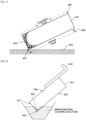
- the cleaning blade 400 is deformed such that the portion of the photoconductor-facing surface 405 expands and the portion of the non-photoconductor-facing surface 406 contracts. In this manner, the cleaning blade 400 evenly comes into contact with the photoconductor 408.
- the non-photoconductor-facing surface 406 other than the edge line portion 403 has its strength increased by the impregnation treatment. Therefore, as shown in Fig. 7 , the portion of the photoconductor-facing surface 405 does not easily expand, the portion of the non-photoconductor-facing surface 406 does not easily contract, and the edge line portion 403 does not easily bend. As a result, the contact with the photoconductor 408 becomes uneven, and the uneven contact causes degradation in cleaning performance. Also, as shown in Fig.
- Fig. 8 which is a schematic diagram for explaining another impregnation treatment
- an impregnated portion 504 is formed on an edge line portion 503 and part of a cut surface 507 formed to be interposed between a photoconductor-facing surface 505 and a non-photoconductor-facing surface 506 and continue to the both surfaces, and the non-photoconductor-facing surface 506 is not immersed in the impregnating coating solution, as shown in Fig. 9 .
- the portion of the non-photoconductor-facing surface 506 is deformed so as to sufficiently contract, and the portion of the photoconductor-facing surface 505 is deformed so as to sufficiently expand. Accordingly, the flexibility of the edge line portion 503 is maintained. In this manner, the contact with a photoconductor (not shown) as the member to be cleaned becomes uniform, and a sufficient effect to increase the strength of the edge line portion 503 is achieved. Thus, cleaning performance can be improved by reducing adhesion of the toner additive to the surface of the photoconductor and to the charging roller.
- the impregnated portion 504 is formed on the portions of the edge line portion 503 and the cut surface 507 but is not formed on the portion of the non-photoconductor-facing surface 506 as in the cleaning blade 500 shown in Fig. 9 .
- the single-layer blade member 501 needs to be made of an elastic material that has a low rate of permanent elongation and a relatively low degree of hardness, as described above.
- the amount of impregnation needs to be made larger than that in a case where an elastic material having a high degree of hardness is used as the base material. Therefore, the impregnation time needs to be made longer, or the concentration of the impregnating coating solution needs to be made higher. This results in an increase in cost due to the elongated production time, or an increase in the cost of the impregnating coating solution due to the increased concentration of the impregnating coating solution.
- Fig. 10 is a schematic diagram for explaining a cleaning blade having a double-layer blade member. It should be noted that any impregnation treatment has not been performed on the blade member shown in Fig. 10 .
- the principal characteristics of Experiment 1 are shown in Table 1.
- the edge layer 601a of the blade member 601 is made of a urethane rubber having a high Young's modulus (16.1 MPa) (high strength), so as to improve cleaning performance, reduce adhesion of the toner additive to the surface of a photoconductor, and reduce staining of the charging roller.
- Young's modulus (16.1 MPa) high strength
- the urethane rubber used as the edge layer 601a which is a single layer, has a permanent elongation rate of 3.2%, as shown in Table 1. Since the rate of permanent elongation is higher than 3.0%, permanent deformation becomes a problem in a cleaning blade having a single-layer blade member.
- a urethane rubber that has a low Young's modulus (6.5 MPa) (low strength) and a permanent elongation rate of 0.5% is used as the backup layer 601b to realize a double-layer structure. As a result, the permanent elongation rate of the entire blade member 601 becomes 1.4%, which is not higher than 3.0% and does not cause the problem of permanent deformation.
- Fig. 11 is a schematic diagram for explaining a cleaning blade having a double-layer blade member. It should be noted that any impregnation treatment has not been performed on the blade member shown in Fig. 11 .
- the film thicknesses and the sizes of the respective layers are the same as those of the cleaning blade used in Experiment 1.
- the principal characteristics of Experiment 2 are shown in Table 2.
- the edge layer 701a of the blade member 701 is made of a high-hardness urethane rubber having an even higher Young's modulus (28.5 MPa) than that in Experiment 1, so as to improve cleaning performance, reduce adhesion of the additive to the surface of a photoconductor, and reduce staining of the charging roller more effectively than in Experiment 1.
- the urethane rubber used as the edge layer 701a which is a single layer, has a permanent elongation rate of 8.3%, which is much higher than 3.0%, as shown in Table 2.
- the permanent elongation rate of the entire blade member 701 is 4.3%, which is higher than 3.0% and causes the problem of permanent deformation. This is supposedly because the permanent elongation rate of the edge layer 701a is higher than that of the backup layer 701b, and the permanent elongation of the edge layer 701a becomes dominant in the permanent elongation of the entire blade member, as described above.
- Fig. 12 is a schematic diagram for explaining a cleaning blade having a double-layer blade member. It should be noted that any impregnation treatment has not been performed on the blade member shown in Fig. 12 .
- the principal characteristics of Experiment 3 are shown in Table 3.
- the portion of a photoconductor-facing surface 804 is formed with a first edge layer 805 as the cleaning layer and a second edge layer 806 as the edge layer.
- the first edge layer 805 is formed in a portion including an edge line portion 803, and becomes gradually thicker in the direction toward the edge line portion 803.
- the first edge layer 805 is made of an elastic material that has a Young's modulus of 28.5 Mpa and a permanent elongation rate of 8.3%, which is not desirable in terms of permanent elongation.
- the proportion of the portion of the first edge layer 805 to the photoconductor-facing surface 804 is lower than that of the portion of the second edge layer 806.
- the permanent elongation of the second edge layer 806 is dominant in the permanent elongation of the entire blade member, and the permanent elongation rate of the entire blade member is 1.4%, which is not higher than 3.0%.
- permanent deformation over time can be reduced, and high cleaning performance can be maintained over a long period of time by virtue of the effect to reduce adhesion of the toner additive to the surface of a photoconductor and the effect to reduce staining of the charging roller.
- the first edge layer (the cleaning layer) is made of an elastic material having a high Young's modulus.
- the elastic power of this material is 39.6%. Normally, when the Young's modulus of an elastic material is made larger, the value of the elastic power thereof tends to become smaller.
- the elastic power is a value indicating a relation between elastic workload and plastic workload, and indicates plastic deformability of the material. In a cleaning blade, the plastic deformability of the edge line portion to be in contact with a photoconductor greatly affects toner removal performance.
- edge line portion of a cleaning blade has a high degree of plastic deformability
- part of the edge line of the cleaning blade is once deformed downstream in the photoconductor moving direction by the frictional force between the cleaning blade and the photoconductor.
- the original edge shape is not easily restored, and toner easily escapes through the site.
- a streaky abnormal image is obtained due to defective cleaning that is caused by the streaky toner escape. Since toner easily continues to escape through the same site, part of the edge line portion becomes locally worn.
- Such degradation of cleaning properties due to a low elastic power occurs notably in low-temperature environments.
- the edge line of each blade was observed with a microscope, and the deformation amount generated by plastic deformation was calculated.
- the plastic deformation amounts of the edge lines are shown below in Table 4.
- the cleaning blade 3-1 having an elastic power of 39.6% was hardly deformed.
- the maximum plastic deformation amounts of the cleaning blades 3-2 and 3-3 were 0.8 ⁇ m and 1.1 ⁇ m, respectively.
- Fig. 15 is a schematic diagram for explaining a cleaning blade having a double-layer blade member. It should be noted that any impregnation treatment has not been performed on the blade member shown in Fig. 15 .
- the principal characteristics of Experiment 5 are shown in Table 5.
- a cleaning blade 900 that includes the double-layer blade member 901 shown in Fig. 15 , the portion of a photoconductor-facing surface 904 is formed with a first edge layer 905 and a second edge layer 906.
- the first edge layer 905 is formed near an edge line portion 903, and becomes gradually thicker in the direction toward the edge line portion 903.
- the Young's modulus of the first edge layer 905 is 16.1 MPa, which is lower than that of the first edge layer 805 shown in Fig. 12 , and the strength of the portion including the edge line portion 903 is not sufficient. Therefore, the cleaning performance is poorer than that of the cleaning blade 800 shown in Fig.
- the proportion of the portion of the second edge layer 906 to the photoconductor-facing surface 804 is higher than that of the portion of the first edge layer 905. Therefore, the permanent elongation due to the Young's modulus of the second edge layer 906 is dominant, and cleaning performance is degraded due to permanent deformation over time.
- the degree of hardness (strength or Young's modulus) of the edge line portion needs to be made higher, so as to realize excellent cleaning performance through a reduction of adhesion of the additive to the photoconductor surface and a reduction of staining of the charging roller.
- the first edge layer is provided most upstream in the photoconductor moving direction, and the second edge layer is provided downstream of the first edge portion. Also, the first edge layer has the highest Young's modulus.
- the second edge layer has a lower Young's modulus than that of the first edge layer
- the backup layer has a lower Young's modulus than that of the second edge layer.
- the backup layer is in contact with the side of the first edge layer and/or the second edge layer opposite to the side of the second edge layer and the edge line portion facing the photoconductor.
- a first edge layer 1005 is formed in a portion including an edge line portion 1003, and the film thickness thereof may become gradually thicker in the direction toward the edge line portion 1003.
- a first edge layer 1105 is formed in a portion including an edge line portion 1103, and may be formed over an edge 1101a and a backup layer 1101b.
- a first edge layer 1205 and a second edge layer 1206 may be formed so that the film thickness of each of the edge layers 1205 and 1206 becomes gradually thicker in the direction toward an edge line portion 1203.
- the portion of the photoconductor-facing surface 1304 of an edge layer 1301a may be formed with a first edge layer 1305 that is made of a high-hardness elastic material and is located in a portion including an edge line portion 1303, and a second edge layer 1306 made of a low-hardness elastic material.
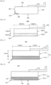
- Fig. 20 is a schematic diagram for explaining the example of a cleaning blade.
- the cleaning blade 1400 of the example shown in Fig. 20 includes a double-layer blade member 1401 formed with an edge layer 1401a and a backup layer 1401b that are made of elastic materials having different degrees of hardness from each other, and a supporting member 1402 that fixes the blade member 1401 to the main frame of the cleaning device and is made of a material having high rigidity, such as a metal.
- the blade member 1401 is fixed to one end of the supporting member 1402 with an adhesive agent or the like, and the other end of the supporting member 1402 is cantilevered by the main frame of the cleaning device.
- an impregnation treatment is performed, so that a region extending from the edge layer 1401a to the backup layer 1401b in a portion including an edge line portion 1403 is impregnated with resin.
- an impregnated portion 1405 as the cleaning layer is formed.
- a portion including the edge line portion 1403 is impregnated with acrylic resin or the like, so that the impregnated portion 1405 has a degree of hardness increased through ultraviolet curing.
- the principal characteristics of the cleaning blade of this example are shown below in Table 6.
- the degrees of Martens hardness [N/mm 2 ] in Table 5 are characteristic values for comparing the impregnated portion subjected to the impregnation treatment with the edge layer and the backup layer.
- the impregnated portion 1405 shown in Fig. 20 is an impregnated portion extending approximately 100 ⁇ m along the photoconductor-facing surface 1404 from the edge line portion 1403. Since this is an extremely narrow region, it is difficult to detect changes in macroscopic characteristics such as a Young's modulus before and after the impregnation treatment. Therefore, there are no numerical values that represent minute changes in hardness and indicate the effect of the impregnation treatment.
- Fig. 21 is a schematic diagram for explaining a comparative example of a cleaning blade.
- the cleaning blade 1500 of the comparative example shown in Fig. 21 includes a strip-shaped single-layer blade member 1501, and a supporting member 1502 that fixes the blade member 1501 to the main frame of the cleaning device and is made of a material having high rigidity, such as a metal.
- an impregnation treatment is performed on a portion including an edge line portion 1503, to form an impregnated portion 1505.
- the portion including the edge line portion 1503 is impregnated with an impregnating coating solution such as acrylic resin, so that the impregnated portion 1505 has a degree of hardness increased through ultraviolet curing.
- the principal characteristics of the cleaning blade of this example are shown below in Table 7.
- the cleaning blade 1400 shown in Fig. 20 and the cleaning blade 1500 shown in Fig. 21 are immersed in and impregnated with the same impregnating coating solution, but require different impregnation treatment periods to obtain the target Martens hardness (at a site 20 ⁇ m away from the edge line portion, for example). If the Young's modulus of the rubber member prior to the impregnation treatment is low or the Martens hardness is low, a long impregnation treatment period is required to achieve the target Martens hardness, and the impregnated region becomes wider. Also, the high-hardness region expands outside the region surrounding the edge line portion. Therefore, as the high-strength region becomes larger, the contact portion of the blade member is not evenly brought into contact with the surface of a photoconductor as the member to be cleaned, and cleaning performance is degraded.
- an impregnated portion 1605 may be formed by performing the impregnation treatment only on the portion of the edge line portion 1603 of an edge layer 1601a while not performing the impregnation treatment on the portion of a backup layer 1601b.
- an impregnated portion 1705 may be formed by performing the impregnation treatment on a portion that extends from an edge layer 1701a to a backup layer 1701b and includes an edge line portion 1703. As shown in Fig.
- an edge layer 1801a in a cleaning blade 1800 that is a third modification, may be designed so that the film thickness thereof becomes gradually greater in the direction toward an edge line portion 1803, and an impregnated portion 1805 may be formed by performing the impregnation treatment only on a portion of the edge layer 1801a including the edge line portion 1803.
- an edge layer 1901a in a cleaning blade 1900 that is a fourth modification, may be designed such that the film thickness thereof becomes gradually greater in the direction toward an edge line portion 1903, and an impregnated portion 1905 may be formed by performing the impregnation treatment only on a portion that extends from the edge layer 1901a to a backup layer 1901b and includes the edge line portion 1903.
- the impregnation treatment is performed on a portion including the edge line portion of a double-layer blade member, so that the double-layer blade member includes at least an edge layer, a backup layer, and an impregnated portion (the cleaning layer). Accordingly, permanent deformation over time can be reduced more effectively than in a single-layer blade member having the impregnation treatment performed on a portion including the edge line portion, and excellent cleaning performance can be maintained through a reduction of adhesion of the toner additive to the surface of a photoconductor and a reduction of staining of the charging roller more effectively than in the single-layer blade member.
- the impregnation treatment for impregnating the cleaning blade 5 shown in Fig. 2 with an ultraviolet curable resin can be performed by brush coating, spray coating, dip coating, or the like.
- the ultraviolet curable resin for impregnation is preferably a material that has a Martens hardness of 250 to 500 N/mm 2 , and an elastic power of 75% or lower, or more preferably, an elastic power of 50 to 75%.
- the Martens hardness and the elastic power of the ultraviolet curable resin for impregnation are the results of measurement carried out on a resin film that was formed on a glass substrate and had a thickness of 5 to 10 ⁇ m.
- the Martens hardness as the hardness of the ultraviolet curable resin was measured with a microhardness measurement instrument, HM-2000, manufactured by Fischer Instruments K.K. Specifically, the ultraviolet curable resin is applied onto a glass substrate so that the thickness becomes 20 ⁇ m. A Vickers indenter is pushed into the applied ultraviolet curable resin with a force of 9.8 mN in 30 seconds, and is kept therein for five seconds. The Vickers indenter is then pulled out with a force of 9.8 mN in 30 seconds. Measurement is carried out in this manner. The elastic power is a characteristic value that is calculated, as described below, from the total stress obtained at the time of the Martens hardness measurement.
- the elastic power is a characteristic value defined by the expression, Welast/Wplast ⁇ 100% (see Fig. 26 ).
- a higher elastic power means smaller hysteresis loss (plastic deformation) or greater rubbery characteristics. If the elastic power is too low, the ultraviolet curable resin is more like glass than rubber.
- the Martens hardness of the portion in the vicinity of the edge line portion 61 shown in Fig. 2 is the Martens hardness measured when the cleaning blade 5 was impregnated with an ultraviolet curable resin, and differs from the Martens hardness of the above described ultraviolet curable resin.
- the ultraviolet curable resin for the impregnation treatment is preferably a material having high hardness and high elasticity, such as an acrylate or methacrylate having a tricyclodecane or adamantane skeleton.
- the toner removal performance is greatly improved, and the wear of the cleaning blade is reduced. Accordingly, excellent cleaning performance can be maintained over a long period of time. Also, the coefficient of friction between the cleaning blade and the photoconductor is reduced, and the wear of the photoconductor is reduced. Accordingly, the life of the photoconductor and the life of the image forming apparatus can be prolonged. Further, as the cleaning blade does not rub the toner additive or the like against the surface of the photoconductor, any abnormal image with blanks is not generated.
- the acrylate or methacrylate having a tricyclodecane or adamantane skeleton is preferable, because the special structure of a tricyclodecane or adamantane skeleton can compensate for shortage of cross-linking points, even if the number of functional groups is small.
- Examples of acrylates or methacrylates having a tricyclodecane or adamantane skeleton include tricyclodecane dimethanol diacrylate, 1,3-adamantane dimethanol diacrylate, 1,3-adamantane dimethanol dimethacrylate, 1,3,5-adamantane trimethanol triacrylate, and 1,3,5-adamantane trimethanol trimethacrylate. A mixture of two or more of these materials may be used.
- the number of functional groups of the acrylate or methacrylate having a tricyclodecane or adamantane skeleton is preferably one to six, and more preferably, two to four. If the number of functional groups is one, the cross-linked structure is weak. If the number of functional groups is five or greater, steric hindrance might occur. Therefore, it is preferable to mix acrylates or methacrylates having different numbers of functional groups.
- the molecular weight of the acrylate or methacrylate having a tricyclodecane or adamantane skeleton is preferably 500 or smaller. If the molecular weight is 500 or greater, the molecular size becomes larger. As a result, the cleaning blade is not easily impregnated with the ultraviolet curable resin, and it becomes difficult to achieve a higher degree of hardness.
- An acrylate monomer of 100 to 1500 in molecular weight may be mixed with the impregnating coating solution for impregnating the cleaning blade 5 with an ultraviolet curable resin by brush coating, spray coating, dip coating, or the like.
- acrylate monomers include dipentaerythritol hexaacrylate, pentaerythritol tetraacrylate, pentaerythritol triacrylate, pentaerythritol ethoxy tetraacrylate, trimethylol propane triacrylate, trimethylol propane ethoxy triacrylate, 1,6-hexanediol diacrylate, ethoxylated bisphenol A diacrylate, propoxylated ethoxylated bisphenol A diacrylate, 1,4-butanediol diacrylate, 1,5-pentanediol diacrylate, 1,6-hexanediol diacrylate, 1,7-heptanediol diacrylate, 1,
- the diluent for the impregnating coating solution can solve an ultraviolet curable resin, and preferably has a low boiling point. Particularly, the boiling point is not higher than 160°C, or more preferably, not higher than 100°C.
- diluting solvents that can be used herein are organic solvents including: hydrocarbon-based solvents such as toluene and xylene; esters such as ethyl acetate, n-butyl acetate, methyl cellosolve acetate, and propylene glycol monomethyl ether acetate; ketones such as methyl ethyl ketone, methyl isobutyl ketone, diisobutyl ketone, cyclohexanone, and cyclopentanone; ethers such as ethylene glycol monomethyl ether, ethylene glycol monoethyl ether, and propylene glycol monomethyl ether; alcohols such as ethanol, propanol, 1-butanol, isopropy
- the above diluent has the effect to facilitate impregnation at the time of coating.
- the above diluent might degrade physical properties and wear resistance, such as when a residual solvent exists in the rubber, and the rubber remains expanded and does not return to its original thickness.
- drying is conducted by heating so as to remove the residual solvent, the physical properties of the rubber are changed, and the cleaning properties might be degraded.
- a low-temperature fixing toner that has a glass transition temperature (Tg) of 40 to 60°C is used so as to save energy in the fixing device 30 of the image forming apparatus.
- the toner of this embodiment is a polyester resin as a binder resin that satisfies the following conditions: 1) the glass transition temperature (Tg) is 39 to 65°C, and 2) the value (Mw/Tg) obtained by dividing the weight-average molecular weight (Mw) of the THF soluble portion by the glass transition temperature (Tg/°C) is 40 to 120.
- the polyester resin In the conventionally-used polyester resin, Mw tends to drop rapidly as Tg becomes lower than 65°C. Therefore, it is difficult for the conventionally-used polyester resin to excel in low-temperature fixability, hot-offset resistance, and heat-resistant preservability. If Tg of the polyester resin is lower than 39°C, the heat-resistant preservability cannot be improved, no matter how well Mw is adjusted. Therefore, the range of Tg that can keep the physical properties of the toner in balance is 39 to 65°C, and the range of the value of Mw/Tg is 40 to 120. As long as the value of Mw/Tg stays within the above range, the polyester resin has such Tg as to maintain excellent heat-resistant preservability, and the molecular weight can also be reduced.
- Mw and Tg are measured by the technique described below, and the unit of Tg in the value of Mw/Tg is°C.
- the glass transition temperature (Tg) is measured at a temperature rise rate of 10°C/min with Rigaku THRMOFLEX TG8110, manufactured by Rigaku Corporation.
- the molecular weight is measured by GPC (gel permeation chromatography) as follows. A column is steadied in a heat chamber at 40°C, and THF is applied as the solvent at a flow rate of 1 ml/min to the column at the temperature. Measurement is then carried out by injecting 50 to 200 ⁇ l of a THF sample solution of a resin adjusted to a sample density of 0.05 to 0.6 wt.%. When the molecular weight of a sample is measured, the molecular weight distribution of the sample is calculated from the relation between the logarithmic value of the created calibration curve and the count number obtained from several kinds of monodisperse polystyrene standard samples.
- GPC gel permeation chromatography
- the appropriate standard polystyrene samples for creating a calibration curve are at least ten standard polystyrene samples, which are manufactured by Pressure-Chemical Co. or Tosoh Corporation, and have molecular weights of 6 ⁇ 102, 2.1 ⁇ 103, 4 ⁇ 103, 1.75 ⁇ 104, 5.1 ⁇ 104, 1.1 ⁇ 105, 3.9 ⁇ 105, 8.6 ⁇ 105, 2 ⁇ 106, and 4.48 ⁇ 106, for example.
- an RI (refractive index) detector is used as the detector.
- the chemical structure of the polyester resin that satisfies the above conditions preferably has the following features. Specifically, the molar ratio (benzene ring skeleton/1,4-cyclohexylene skeleton) between the benzene ring skeleton and the 1,4-cyclohexylene skeleton in the polyester resin is 2.0 to 15.0, and the molar ratio (benzene skeleton/double-end ester-bond alkylene skeleton) between the benzene skeleton and the alkylene skeleton having ester bonds at both ends is 3.0 or higher.
- the glass transition temperature (Tg) of the polyester resin is governed mainly by its chemical structure, and Tg tends to become higher as the benzene ring skeleton extends longer or the content of the benzene ring skeleton becomes larger. Also, Tg tends to become lower, as the alkylene skeleton becomes longer or the content of the alkylene skeleton becomes larger. Therefore, if the content of the benzene ring skeleton is large, the hot-offset resistance and the heat-resistant preservability are improved, but the low-temperature fixability are degraded. If the content of the alkylene skeleton is large, the low-temperature fixability is advantageously improved, but the hot-offset resistance and the heat-resistant preservability is adversely affected. Meanwhile, with an appropriate amount of the 1,4-cyclohexylene skeleton, the weight-average molecular weight of the resin can be adjusted while Tg is maintained. Accordingly, the low-temperature fixability can be further improved.
- the ranges of the molar ratio (benzene ring skeleton/1,4-cyclohexylene skeleton) and the molar ratio (benzene skeleton/double-end ester-bond alkylene skeleton) are specified as described above. If the molar ratio (benzene ring skeleton/ 1,4-cyclohexylene skeleton) is lower than 2.0, the polyester resin becomes brittle, and the toner loses its durability. If the molar ratio (benzene ring skeleton/ 1,4-cyclohexylene skeleton) is higher than 15.0, it becomes difficult to reduce the molecular weight while maintaining the glass transition temperature, and therefore, low-temperature fixability cannot be achieved. Further, if the molar ratio (benzene skeleton/double-end ester-bond alkylene skeleton) is lower than 3.0, it is difficult to maintain heat-resistant preservability.
- the molar ratio (benzene ring skeleton/1,4-cyclohexylene skeleton) and the molar ratio (benzene skeleton/double-end ester-bond alkylene skeleton) can be calculated from the raw-material composition ratio between polyprotic carboxylic acid and polyhydric alcohol, which are the raw materials of the resin.
- these molar ratios can be calculated by carrying out 1H-NMR (nuclear magnetic resonance) measurement on the generated resin.
- Mw of the THF soluble portion of the polyester resin is preferably set at 2,000 to 7,800 in the present invention. If Mw is less than 2,000, the oligomer component increases. Therefore, even if the chemical structure is controlled as described above, the heat-resistant preservability is degraded. If Mw exceeds 7,800, the melting temperature becomes higher, and the low-temperature fixability is degraded.
- the toner characteristics such as low-temperature fixability, hot-offset resistance, heat-resistant preservability, and charging stability can also be improved by adjusting the acid value of the polyester resin to 1.0 to 50.0 KOHmg/g.
- the low-temperature fixing toner of this embodiment can be manufactured by using the above described polyester resin as the binder resin, and mixing therein a polymer (hereinafter referred to as the "prepolymer") having parts that are reactive with a compound containing active hydrogen groups as described later in detail.
- a polymer hereinafter referred to as the "prepolymer”
- this prepolymer is mixed with a compound containing active hydrogen groups, elongation or a cross-linking reaction can be caused during the toner manufacturing process, and the above toner characteristics can be improved.
- the acid value of the polyester resin exceeds 50.0 KOHmg/g, the elongation or the cross-linking reaction of the prepolymer becomes insufficient, and the hot-offset resistance is adversely affected. If the acid value is smaller than 1.0 KOHmg/g, the elongation or the cross-linking reaction of the prepolymer is easily facilitated, and a problem is caused in production stability.
- the acid value of the polyester resin is measured by a method compliant with JIS K0070. However, if a sample is not dissolved, dioxane or THF is used as the solvent, for example. Further study indicates that not only the acid value of the polyester resin but also the acid value of the toner is critical in maintaining low-temperature fixability and hot-offset resistance.
- the acid value of the toner is preferably 0.5 to 40.0 KOHmg/ g. If the acid value of the toner exceeds 40.0 KOHmg/g, the elongation or the cross-linking reaction of the prepolymer becomes insufficient, and the hot-offset resistance is adversely affected.
- the acid value is smaller than 0.5 KOHmg/g, the elongation or the cross-linking reaction of the prepolymer is easily facilitated, and a problem is caused in production stability.
- the acid value of the toner can be measured in the same manner as the measurement of the acid value of the polyester resin.
- the glass transition temperature of the toner is preferably 40 to 60°C. If the glass transition temperature is lower than 40°C, toner blocking in the developing machine or filming on the photoconductor easily occurs. If the glass transition temperature exceeds 60°C, the low-temperature fixability is easily degraded.
- the glass transition temperature of the toner can be measured in the same manner as the measurement of the glass transition temperature of the polyester resin.
- the volume-average particle diameter (Dv) of the toner is preferably 3 to 8 ⁇ m, and more preferably, the ratio (Dv/Dn) of the volume-average particle diameter (Dv) to the number-average particle diameter (Dn) is in a range of 1.00 to 1.25.
- Dv/Dn is specified in this manner, a toner having high resolution and high image quality can be obtained. So as to obtain an image with even higher quality, Dv is preferably set at 3 to 7 ⁇ m, Dv/Dn is preferably set at 1.00 to 1.20, and the number of particles of 3 ⁇ m or smaller is preferably set at 1 to 10 in percentage.
- Dv is set at 3 to 6 ⁇ m
- Dv/Dn is set at 1.00 to 1.15.
- Such a toner excels in heat-resistant preservability, low-temperature fixability, and hot-offset resistance. Particularly, such a toner excels in image glossiness when used in a full-color copying machine or the like. Further, in a two-component developer, even if the toner is supplied and consumed over a long period of time, variations in the particle diameter of the toner in the developer become smaller. Even if the toner is stirred in the developing device over a long period of time, preferred stable developing properties can be achieved.
- the average particle size and the granularity distribution of the toner were measured with a Coulter counter Type TA-II, to which an interface that outputs a number distribution and a volume distribution (manufactured by the Institute of Japanese Union of Engineers) and a PC9801 personal computer (manufactured by NEC Corporation) were connected.
- the weight-average molecular weight (Mw) of the THF soluble portion was 2,900, the acid value was 5 KOHmg/g, and the glass transition temperature (Tg) was 43°C.
- the ratio (Mw/Tg) between the weight-average molecular weight and the glass transition temperature was 67.
- the molar ratio between the benzene ring skeleton and the 1,4-cyclohexylene skeleton was 9.5, and the molar ratio between the benzene ring skeleton and double-end ester-bond alkylene skeleton was 3.2.
- polyester resin (PE2) was then obtained in the same manner as in Example Preparation 1.
- Mw weight-average molecular weight
- THF glass transition temperature
- Tg glass transition temperature
- the molar ratio between the benzene ring skeleton and the 1,4-cyclohexylene skeleton was 13.5, and the molar ratio between the benzene ring skeleton and double-end ester-bond alkylene skeleton was 27.0.
- a polyester resin (PE3) was then obtained in the same manner as in Example Preparation 1.
- the weight-average molecular weight (Mw) of the THF soluble portion was 3,300
- the acid value was 7 KOHmg/g
- the glass transition temperature (Tg) was 43°C.
- the ratio (Mw/Tg) between the weight-average molecular weight and the glass transition temperature was 77.
- the molar ratio between the benzene ring skeleton and the 1,4-cyclohexylene skeleton was 5.6, and the molar ratio between the benzene ring skeleton and double-end ester-bond alkylene skeleton was 7.5.
- a polyester resin (PE4) was then obtained in the same manner as in Example Preparation 1.
- the weight-average molecular weight (Mw) of the THF soluble portion was 6,500
- the acid value was 28 KOHmg/g
- the glass transition temperature (Tg) was 62°C.
- the ratio (Mw/Tg) between the weight-average molecular weight and the glass transition temperature was 105.
- the molar ratio between the benzene ring skeleton and the 1,4-cyclohexylene skeleton was 2.7, and the molar ratio between the benzene ring skeleton and double-end ester-bond alkylene skeleton was 35.7.
- polyester resins (PE1) through (PE4) used in the toners (I) through (IV) are shown below in Table 8.
- a polyester resin (PE5) was then obtained in the same manner as in Example Preparation 1.
- the weight-average molecular weight (Mw) of the THF soluble portion was 2,500
- the acid value was 9 KOHmg/g
- the glass transition temperature (Tg) was 35°C.
- the ratio (Mw/Tg) between the weight-average molecular weight and the glass transition temperature was 71.
- the molar ratio between the benzene ring skeleton and the 1,4-cyclohexylene skeleton was 18.5, and the molar ratio between the benzene ring skeleton and double-end ester-bond alkylene skeleton was 4.8.
- a polyester resin (PE6) was then obtained in the same manner as in Example Preparation 1.
- the weight-average molecular weight (Mw) of the THF soluble portion was 5,700
- the acid value was 18 KOHmg/g
- the glass transition temperature (Tg) was 45°C.
- the ratio (Mw/Tg) between the weight-average molecular weight and the glass transition temperature was 127.
- the molar ratio between the benzene ring skeleton and the 1,4-cyclohexylene skeleton was 2.4, and the molar ratio between the benzene ring skeleton and double-end ester-bond alkylene skeleton was 2.6.
- a polyester resin (PE7) was then obtained in the same manner as in Example Preparation 1.
- the weight-average molecular weight (Mw) of the THF soluble portion was 5,000
- the acid value was 11 KOHmg/g
- the glass transition temperature (Tg) was 41°C.
- the ratio (Mw/Tg) between the weight-average molecular weight and the glass transition temperature was 122.
- the molar ratio between the benzene ring skeleton and the 1,4-cyclohexylene skeleton was 10.8, and the molar ratio between the benzene ring skeleton and double-end ester-bond alkylene skeleton was 2.6.
- polyester resins (PE5) through (PE7) used in the toners (V) through (VII) are shown below in Table 9.
- the fixing temperature was varied, to determine a cold offset temperature (the lower fixing temperature limit) and a hod offset temperature (a hot-offset-resistant temperature).
- the lower fixing temperature limit of a conventional low-temperature fixing toner is approximately 140 to 150°C.
- the conditions under which low-temperature fixability was evaluated are as follows.
- the linear velocity of paper sheet feeding is 120 to 150 mm/sec, the surface pressure was 1.2 kgf/cm 2 , and the nip width was 3 mm.
- the linear velocity of paper sheet feeding was 50 mm/sec
- the surface pressure was 2.0 kgf/cm 2
- the nip width was 4.5 mm.
- the toners (I) through (IV), (VI), and (VII) having glass transition temperatures (Tg) between 40°C and 61°C achieved excellent low-temperature fixability, high hot-offset resistances, and excellent heat-resistant preservability.
- the toner (V) having a lower glass transition temperature (Tg) than 40°C was excellent in low-temperature fixability and hot-offset resistance, but was poor in heat-resistant preservability, as indicated by "E” in the column of heat-resistant preservability.
- a cleaning blade 1400 is formed with a blade member 1401 having a stack structure of elastic materials having different degrees of hardness from each other, the edge line portion 1403 of the blade member 1401 being brought into contact with the surface of a cleaning target member such as a photoconductor 10 performing surface movement, the blade member 1401 removing adhering matter from the surface of the photoconductor 10.
- the cleaning layer including the edge line portion 1403 is impregnated with a resin or is made of an elastic material having a high degree of hardness, and the permanent elongation rate of the entire blade member is set at 3.0% or lower.
- the cleaning layer including the edge line portion 1403 is impregnated with a resin or is made of an elastic material having a high degree of hardness. Also, the permanent elongation rates of the edge layer 1401a, the backup layer 1401b, and the edge line portion 1403 are combined, so that the permanent elongation rate of the entire blade member is set at 3.0% or lower.
- the deformation of the edge line portion 1403 brought into contact with the photoconductor 10 is small, an increase in the contact area can be prevented, and the contact pressure can be increased. Further, permanent deformation over time can be effectively reduced.
- the backup layer 1401b bonded to the edge layer 1401a in contact with the photoconductor 10 has a lower degree of hardness and a lower permanent elongation rate than the edge layer 1401a and the edge line portion 1403, and accordingly, permanent deformation over time is reduced in the entire blade member.
- the permanent elongation rate of the entire blade member is set at 3.0% or lower, permanent deformation can be made smaller than that in the cleaning blade disclosed in Patent Document 1, even if the blade member 1401 stays in contact with the photoconductor 10 over a long period of time. Accordingly, the initial contact state can be maintained.
- the cleaning layer including the edge line portion 1403 of the blade member 1401 is subjected to the impregnation treatment to obtain a higher degree of hardness, or the cleaning layer is made of an elastic material having a high degree of hardness, so that the degree of hardness of the edge line portion 1403 is made higher than those of the edge layer 1401a and the backup layer 1401b, and the contact pressure can be set at a high value. Accordingly, when the edge line portion 1403 is brought into contact with the photoconductor 10, the deformation of the edge line portion 1403 is small, an increase of the contact area can be prevented, and cleaning performance can be improved.
- the blade member 1401 includes: the cleaning layer such as an impregnated portion 1405 including the edge line portion 1403; the edge layer 1401a having a surface facing the surface of the photoconductor 10; and the backup layer 1401b having a non-photoconductor-facing surface opposite to the photoconductor-facing surface 1404, and the degrees of hardness of the elastic materials of the impregnated portion 1405, the edge layer 1401a, and the backup layer 1401b differ from one another.
- the cleaning layer such as an impregnated portion 1405 including the edge line portion 1403
- the edge layer 1401a having a surface facing the surface of the photoconductor 10
- the backup layer 1401b having a non-photoconductor-facing surface opposite to the photoconductor-facing surface 1404
- the degrees of hardness of the elastic materials of the impregnated portion 1405, the edge layer 1401a, and the backup layer 1401b differ from one another.
- a blade member is formed with a double-layer stack structure including at least an edge layer and a backup layer, and the edge line portion 1403 is made to have a higher degree of hardness through an impregnation treatment as described above in an example of the embodiment.
- this blade member differs from a single-layer blade member in which the edge line portion is made to have a higher degree of hardness through an impregnation treatment. Accordingly, an increase in cost due to a prolonged production time or an increase in cost of the impregnating coating solution due to an increase in the concentration of the impregnating coating solution, and permanent deformation over time can be prevented. At the same time, excellent cleaning performance can be maintained over a long period of time.
- the Young's modulus of the elastic material of the impregnated portion 1405 is higher than those of the edge layer 1401a and the backup layer 1401b.
- the Young's modulus of the impregnated portion 1405 including the edge line portion 1403 is made higher than those of the edge layer 1401a and the backup layer 1401b, and accordingly, the contact pressure with which the edge line portion 1403 is to be brought into contact with the image bearer can be set at a high value, as described above in an example of the embodiment.
- the Young's modulus of the elastic material of the impregnated portion 1405 is higher than that of the edge layer 1401a, and the Young's modulus of the elastic material of the edge layer 1401a is higher than that of the backup layer 1401b.
- the Young's modulus of the edge line portion 1403 is made higher than those of the edge layer 1401a and the backup layer 1401b, and accordingly, the contact pressure can be set at a high value, as described above in an example of the embodiment.
- the backup layer 1401b has a lower Young's modulus and a lower permanent elongation rate than those of the edge layer 1401a, permanent deformation over time can be reduced in the entire blade member. Accordingly, even if the blade member 1401 is kept in contact with the photoconductor 10 over a long period of time, permanent deformation does not easily occur, and the initial contact state can be maintained.
- the elastic power of the portion in the vicinity of the edge line portion of the cleaning layer is 40% or higher.
- a cross-linked structure is formed with an ultraviolet curable resin containing at least an acrylate or methacrylate having a tricyclodecane or adamantane skeleton.
- the toner removal performance is greatly improved, the wear of the cleaning blade is reduced, and excellent cleaning performance can be maintained over a long period of time, as mentioned above in the description of the embodiment.
- the coefficient of friction between the cleaning blade and the photoconductor is reduced, and the wear of the photoconductor is reduced. Accordingly, the life of the photoconductor and the life of the image forming apparatus can be prolonged. Further, as the cleaning blade does not rub the toner additive or the like against the surface of the photoconductor, any abnormal image with blanks is not generated.
- the number of functional groups of the acrylate or methacrylate having a tricyclodecane or adamantane skeleton is one to six.
- the hardness of the edge line portion of the blade member can be further increased. Accordingly, too large deformation of the edge line portion of the blade member can be prevented, the contact pressure can be made higher, and permanent deformation can be reduced. At the same time, excellent cleaning performance can be maintained over a long period of time, as mentioned above in the description of the embodiment.
- the acrylate or methacrylate having the tricyclodecane or adamantane skeleton has a molecular weight of 500 or smaller.
- the molecular weight of the acrylate or methacrylate having the tricyclodecane or adamantane skeleton is 500 or smaller. Accordingly, the molecular size becomes smaller, and impregnating the cleaning blade becomes easier, facilitating an increase in hardness, as mentioned above in the description of the embodiment.
- an acrylate monomer having the molecular weight of 100 to 1500 is mixed with the acrylate or methacrylate having a tricyclodecane or adamantane skeleton.
- an acrylate monomer having a molecular weight of 100 to 1500 is mixed with the acrylate or methacrylate having the tricyclodecane or adamantane skeleton, so that the blade member can be impregnated with a resin by brush coating, spray coating, dip coating, or the like, as mentioned above in the description of the embodiment.
- An image forming apparatus includes: an image bearer such as a photoconductor 10; and a cleaning member that is in contact with the surface of the image bearer to remove adhering matter adhering to the surface of the image bearer.
- an image formed on the image bearer is eventually transferred onto a recording medium, and the cleaning blade of any of (Mode A) through (Mode I) is used as the cleaning member.
- the image bearer can be properly cleaned over a long period of time, and excellent image formation can be performed, as mentioned above in the description of the embodiment.
- a process cartridge 121 that is detachably attached to an image forming apparatus includes: an image bearer such as a photoconductor 10; and a cleaning member that is in contact with the surface of the image bearer to remove adhering matter adhering to the surface of the image bearer.
- an image bearer such as a photoconductor 10
- a cleaning member that is in contact with the surface of the image bearer to remove adhering matter adhering to the surface of the image bearer.
- the cleaning blade of any of (Mode A) through (Mode I) is used as the cleaning member.
- cleaning performance can be improved while permanent deformation of the blade member over time is reduced, as mentioned above in the description of the embodiment. Also, with the form of a process cartridge, higher operability can be achieved.
Landscapes
- Physics & Mathematics (AREA)
- General Physics & Mathematics (AREA)
- Engineering & Computer Science (AREA)
- Computer Vision & Pattern Recognition (AREA)
- Cleaning In Electrography (AREA)
Applications Claiming Priority (3)
| Application Number | Priority Date | Filing Date | Title |
|---|---|---|---|
| JP2014156878 | 2014-07-31 | ||
| JP2014215194A JP2016035550A (ja) | 2014-07-31 | 2014-10-22 | クリーニングブレード、画像形成装置及びプロセスカートリッジ |
| PCT/JP2015/003867 WO2016017184A1 (en) | 2014-07-31 | 2015-07-31 | Cleaning blade, image forming apparatus, and process cartridge |
Publications (3)
| Publication Number | Publication Date |
|---|---|
| EP3175301A1 EP3175301A1 (en) | 2017-06-07 |
| EP3175301A4 EP3175301A4 (en) | 2017-08-09 |
| EP3175301B1 true EP3175301B1 (en) | 2025-06-18 |
Family
ID=55217093
Family Applications (1)
| Application Number | Title | Priority Date | Filing Date |
|---|---|---|---|
| EP15828136.0A Active EP3175301B1 (en) | 2014-07-31 | 2015-07-31 | Cleaning blade, image forming apparatus, and process cartridge |
Country Status (6)
Families Citing this family (9)
| Publication number | Priority date | Publication date | Assignee | Title |
|---|---|---|---|---|
| JP6833412B2 (ja) * | 2016-09-01 | 2021-02-24 | キヤノン株式会社 | クリーニングブレード及び画像形成装置 |
| JP2018132736A (ja) * | 2017-02-17 | 2018-08-23 | 株式会社リコー | クリーニングブレード、プロセスカートリッジ及び画像形成装置 |
| US20180373198A1 (en) * | 2017-06-26 | 2018-12-27 | Hiroshi Mizusawa | Process cartridge and image forming apparatus |
| JP7206743B2 (ja) * | 2018-09-25 | 2023-01-18 | 富士フイルムビジネスイノベーション株式会社 | クリーニングブレード、クリーニング装置、プロセスカートリッジ、及び画像形成装置 |
| CN109642039B (zh) * | 2018-11-28 | 2021-08-17 | 深圳创怡兴实业有限公司 | 橡胶刮板及其制备方法 |
| JP7388161B2 (ja) | 2019-12-06 | 2023-11-29 | 株式会社リコー | 画像形成装置および画像形成方法 |
| JP7456254B2 (ja) | 2020-04-15 | 2024-03-27 | 株式会社リコー | 画像形成装置 |
| JP2022164315A (ja) | 2021-04-16 | 2022-10-27 | 株式会社リコー | クリーニングブレード、画像形成装置、プロセスカートリッジ |
| JP2023105448A (ja) | 2022-01-19 | 2023-07-31 | 株式会社リコー | 画像形成装置 |
Citations (4)
| Publication number | Priority date | Publication date | Assignee | Title |
|---|---|---|---|---|
| JPH09127846A (ja) * | 1995-11-06 | 1997-05-16 | Bando Chem Ind Ltd | 電子写真装置用ブレード体 |
| JP2004046145A (ja) * | 2002-05-22 | 2004-02-12 | Hokushin Ind Inc | ブレード部材 |
| JP2004233818A (ja) * | 2003-01-31 | 2004-08-19 | Tokai Rubber Ind Ltd | 電子写真機用ブレードおよびその製法 |
| US20100247188A1 (en) * | 2009-03-25 | 2010-09-30 | Fuji Xerox Co., Ltd. | Cleaning device and image forming apparatus using the same |
Family Cites Families (25)
| Publication number | Priority date | Publication date | Assignee | Title |
|---|---|---|---|---|
| EP1463860A1 (en) | 2002-01-11 | 2004-10-06 | S.D. Warren Services Company | Composite doctor blades |
| JP2007041202A (ja) * | 2005-08-02 | 2007-02-15 | Ricoh Co Ltd | 転写評価装置、これを用いた画像形成方法および画像形成装置 |
| JP5060730B2 (ja) * | 2006-02-09 | 2012-10-31 | 株式会社ブリヂストン | 導電性ローラ及びそれを備えた画像形成装置 |
| JP4818945B2 (ja) * | 2007-01-29 | 2011-11-16 | バンドー化学株式会社 | 電子写真装置用ブレード及びその製造方法 |
| JP5319170B2 (ja) * | 2008-06-11 | 2013-10-16 | バンドー化学株式会社 | クリーニングブレード及びその製造方法 |
| JP5436846B2 (ja) * | 2008-12-11 | 2014-03-05 | バンドー化学株式会社 | 電子写真用クリーニングブレード用のポリウレタン製弾性ゴム部材及びクリーニングブレード |
| JP5304218B2 (ja) * | 2008-12-18 | 2013-10-02 | 株式会社リコー | 画像形成装置 |
| JP4900413B2 (ja) | 2009-03-27 | 2012-03-21 | 富士ゼロックス株式会社 | 画像形成装置、及びプロセスカートリッジ |
| JP2010262158A (ja) * | 2009-05-08 | 2010-11-18 | Oki Data Corp | 画像形成装置 |
| JP5516936B2 (ja) * | 2009-07-23 | 2014-06-11 | 株式会社リコー | 画像形成装置 |
| JP5482278B2 (ja) * | 2010-02-17 | 2014-05-07 | 株式会社リコー | 電子写真感光体、画像形成装置および画像形成用プロセスカートリッジ |
| JP5633775B2 (ja) | 2010-03-18 | 2014-12-03 | 株式会社リコー | クリーニング装置、並びに、これを備える画像形成装置、プロセスカートリッジ、中間転写ユニット及び記録体搬送ユニット |
| JP2011197311A (ja) * | 2010-03-18 | 2011-10-06 | Ricoh Co Ltd | クリーニング装置、並びに、これを備える画像形成装置、プロセスカートリッジ、中間転写ユニット及び記録体搬送ユニット |
| JP5310619B2 (ja) | 2010-03-19 | 2013-10-09 | コニカミノルタ株式会社 | 画像形成装置 |
| JP2011203303A (ja) * | 2010-03-24 | 2011-10-13 | Fuji Xerox Co Ltd | クリーニングブレードおよび画像形成装置 |
| JP5910939B2 (ja) * | 2011-09-12 | 2016-04-27 | 株式会社リコー | クリーニングブレード、画像形成装置、プロセスカートリッジ |
| JP2013064899A (ja) | 2011-09-19 | 2013-04-11 | Ricoh Co Ltd | 画像形成装置 |
| JP2014066767A (ja) | 2012-09-24 | 2014-04-17 | Ricoh Co Ltd | クリーニングブレードおよび画像形成装置 |
| JP6007702B2 (ja) * | 2012-09-25 | 2016-10-12 | 富士ゼロックス株式会社 | クリーニングブレード、クリーニング装置、プロセスカートリッジ、および画像形成装置 |
| EP2903377B1 (en) | 2012-09-26 | 2017-08-02 | Kyocera Corporation | Mobile communication system |
| JP6128424B2 (ja) | 2012-10-25 | 2017-05-17 | 株式会社リコー | 画像形成装置及びプロセスカートリッジ |
| JP6032549B2 (ja) | 2012-12-11 | 2016-11-30 | 株式会社リコー | 画像形成装置 |
| JP6149669B2 (ja) | 2012-12-26 | 2017-06-21 | 株式会社リコー | クリーニングブレード、画像形成装置、プロセスカートリッジ、及び画像形成方法 |
| JP2014224960A (ja) | 2013-01-10 | 2014-12-04 | 株式会社リコー | クリーニング装置、プロセスカートリッジ、及び画像形成装置 |
| JP6332730B2 (ja) | 2013-05-17 | 2018-05-30 | 株式会社リコー | クリーニングブレード、画像形成装置およびプロセスカートリッジ |
-
2014
- 2014-10-22 JP JP2014215194A patent/JP2016035550A/ja active Pending
-
2015
- 2015-07-31 EP EP15828136.0A patent/EP3175301B1/en active Active
- 2015-07-31 RU RU2017102678A patent/RU2665337C1/ru active
- 2015-07-31 CN CN201580040938.9A patent/CN106662836A/zh active Pending
- 2015-07-31 US US15/324,513 patent/US10031466B2/en active Active
- 2015-07-31 WO PCT/JP2015/003867 patent/WO2016017184A1/en active IP Right Grant
Patent Citations (4)
| Publication number | Priority date | Publication date | Assignee | Title |
|---|---|---|---|---|
| JPH09127846A (ja) * | 1995-11-06 | 1997-05-16 | Bando Chem Ind Ltd | 電子写真装置用ブレード体 |
| JP2004046145A (ja) * | 2002-05-22 | 2004-02-12 | Hokushin Ind Inc | ブレード部材 |
| JP2004233818A (ja) * | 2003-01-31 | 2004-08-19 | Tokai Rubber Ind Ltd | 電子写真機用ブレードおよびその製法 |
| US20100247188A1 (en) * | 2009-03-25 | 2010-09-30 | Fuji Xerox Co., Ltd. | Cleaning device and image forming apparatus using the same |
Also Published As
| Publication number | Publication date |
|---|---|
| WO2016017184A1 (en) | 2016-02-04 |
| US10031466B2 (en) | 2018-07-24 |
| JP2016035550A (ja) | 2016-03-17 |
| RU2665337C1 (ru) | 2018-08-29 |
| US20170199493A1 (en) | 2017-07-13 |
| EP3175301A1 (en) | 2017-06-07 |
| EP3175301A4 (en) | 2017-08-09 |
| CN106662836A (zh) | 2017-05-10 |
Similar Documents
| Publication | Publication Date | Title |
|---|---|---|
| EP3175301B1 (en) | Cleaning blade, image forming apparatus, and process cartridge | |
| US9170557B2 (en) | Cleaning blade, image forming apparatus, and process cartridge | |
| EP2879003B1 (en) | Cleaning blade, image forming apparatus, and process cartridge | |
| EP1835352B1 (en) | Toner, process cartridge, and image forming method | |
| KR101600228B1 (ko) | 현상 장치 및 전자 사진 화상 형성 장치 | |
| US7903998B2 (en) | Image forming apparatus | |
| JP5709065B2 (ja) | トナー、該トナーを用いた現像剤、画像形成装置 | |
| EP2749964B1 (en) | Image forming apparatus, process cartridge, and image forming method | |
| KR101878086B1 (ko) | 토너, 현상제, 및 화상 형성 장치 | |
| EP1624349A2 (en) | Toner, fixer and image forming apparatus | |
| JP6323755B2 (ja) | ブレード部材、画像形成装置およびプロセスカートリッジ | |
| JP6387701B2 (ja) | 画像形成装置及びプロセスカートリッジ | |
| JP2020148893A (ja) | 画像形成装置及び画像形成方法 | |
| CN114631063A (zh) | 显影装置、电子照相处理盒和电子照相图像形成设备 | |
| US9244423B2 (en) | Cleaning blade, and image forming apparatus and process cartridge using the cleaning blade | |
| JP5252302B2 (ja) | 現像ローラ、並びにこれを用いた現像装置、プロセスカートリッジ及び画像形成装置 | |
| US9726995B2 (en) | Brilliant toner, electrostatic charge image developer, and toner cartridge | |
| JP2010164812A (ja) | 1成分画像形成装置 | |
| JP2017021256A (ja) | 画像形成方法 | |
| JP2016173386A (ja) | クリーニングブレード、プロセスカートリッジ及び画像形成装置 | |
| JP6443746B2 (ja) | クリーニングブレード、プロセスカートリッジ、及び画像形成装置 | |
| US12292706B2 (en) | Image forming apparatus and image forming method | |
| EP4239412A1 (en) | Toner, developer, toner housing unit, image forming apparatus, and method of forming image | |
| WO2022219979A1 (en) | Cleaning blade, image forming apparatus, and process cartridge | |
| JP7180423B2 (ja) | 画像形成方法、画像形成装置およびプロセスカートリッジ |
Legal Events
| Date | Code | Title | Description |
|---|---|---|---|
| STAA | Information on the status of an ep patent application or granted ep patent |
Free format text: STATUS: THE INTERNATIONAL PUBLICATION HAS BEEN MADE |
|
| 17P | Request for examination filed |
Effective date: 20170112 |
|
| AK | Designated contracting states |
Kind code of ref document: A1 Designated state(s): AL AT BE BG CH CY CZ DE DK EE ES FI FR GB GR HR HU IE IS IT LI LT LU LV MC MK MT NL NO PL PT RO RS SE SI SK SM TR |
|
| AX | Request for extension of the european patent |
Extension state: BA ME |
|
| PUAI | Public reference made under article 153(3) epc to a published international application that has entered the european phase |
Free format text: ORIGINAL CODE: 0009012 |
|
| STAA | Information on the status of an ep patent application or granted ep patent |
Free format text: STATUS: REQUEST FOR EXAMINATION WAS MADE |
|
| A4 | Supplementary search report drawn up and despatched |
Effective date: 20170712 |
|
| RIC1 | Information provided on ipc code assigned before grant |
Ipc: G03G 21/00 20060101AFI20170706BHEP Ipc: G03G 15/00 20060101ALI20170706BHEP |
|
| DAV | Request for validation of the european patent (deleted) | ||
| DAX | Request for extension of the european patent (deleted) | ||
| STAA | Information on the status of an ep patent application or granted ep patent |
Free format text: STATUS: EXAMINATION IS IN PROGRESS |
|
| 17Q | First examination report despatched |
Effective date: 20210430 |
|
| STAA | Information on the status of an ep patent application or granted ep patent |
Free format text: STATUS: EXAMINATION IS IN PROGRESS |
|
| GRAP | Despatch of communication of intention to grant a patent |
Free format text: ORIGINAL CODE: EPIDOSNIGR1 |
|
| STAA | Information on the status of an ep patent application or granted ep patent |
Free format text: STATUS: GRANT OF PATENT IS INTENDED |
|
| INTG | Intention to grant announced |
Effective date: 20250124 |
|
| GRAS | Grant fee paid |
Free format text: ORIGINAL CODE: EPIDOSNIGR3 |
|
| GRAA | (expected) grant |
Free format text: ORIGINAL CODE: 0009210 |
|
| STAA | Information on the status of an ep patent application or granted ep patent |
Free format text: STATUS: THE PATENT HAS BEEN GRANTED |
|
| P01 | Opt-out of the competence of the unified patent court (upc) registered |
Free format text: CASE NUMBER: APP_17612/2025 Effective date: 20250410 |
|
| AK | Designated contracting states |
Kind code of ref document: B1 Designated state(s): AL AT BE BG CH CY CZ DE DK EE ES FI FR GB GR HR HU IE IS IT LI LT LU LV MC MK MT NL NO PL PT RO RS SE SI SK SM TR |
|
| REG | Reference to a national code |
Ref country code: GB Ref legal event code: FG4D |
|
| REG | Reference to a national code |
Ref country code: CH Ref legal event code: EP |
|
| REG | Reference to a national code |
Ref country code: DE Ref legal event code: R096 Ref document number: 602015091845 Country of ref document: DE |
|
| REG | Reference to a national code |
Ref country code: CH Ref legal event code: EP |
|
| REG | Reference to a national code |
Ref country code: IE Ref legal event code: FG4D |
|
| PGFP | Annual fee paid to national office [announced via postgrant information from national office to epo] |
Ref country code: NL Payment date: 20250721 Year of fee payment: 11 |