EP3132964B1 - Multifunktionsbetriebswerkzeug, armlehnenbetriebsvorrichtung und arbeitsfahrzeug - Google Patents
Multifunktionsbetriebswerkzeug, armlehnenbetriebsvorrichtung und arbeitsfahrzeug Download PDFInfo
- Publication number
- EP3132964B1 EP3132964B1 EP16193594.5A EP16193594A EP3132964B1 EP 3132964 B1 EP3132964 B1 EP 3132964B1 EP 16193594 A EP16193594 A EP 16193594A EP 3132964 B1 EP3132964 B1 EP 3132964B1
- Authority
- EP
- European Patent Office
- Prior art keywords
- operator
- grip part
- operation tool
- multifunction
- switch
- Prior art date
- Legal status (The legal status is an assumption and is not a legal conclusion. Google has not performed a legal analysis and makes no representation as to the accuracy of the status listed.)
- Active
Links
Images


Classifications
-
- B—PERFORMING OPERATIONS; TRANSPORTING
- B60—VEHICLES IN GENERAL
- B60K—ARRANGEMENT OR MOUNTING OF PROPULSION UNITS OR OF TRANSMISSIONS IN VEHICLES; ARRANGEMENT OR MOUNTING OF PLURAL DIVERSE PRIME-MOVERS IN VEHICLES; AUXILIARY DRIVES FOR VEHICLES; INSTRUMENTATION OR DASHBOARDS FOR VEHICLES; ARRANGEMENTS IN CONNECTION WITH COOLING, AIR INTAKE, GAS EXHAUST OR FUEL SUPPLY OF PROPULSION UNITS IN VEHICLES
- B60K26/00—Arrangements or mounting of propulsion unit control devices in vehicles
- B60K26/02—Arrangements or mounting of propulsion unit control devices in vehicles of initiating means or elements
-
- A—HUMAN NECESSITIES
- A01—AGRICULTURE; FORESTRY; ANIMAL HUSBANDRY; HUNTING; TRAPPING; FISHING
- A01B—SOIL WORKING IN AGRICULTURE OR FORESTRY; PARTS, DETAILS, OR ACCESSORIES OF AGRICULTURAL MACHINES OR IMPLEMENTS, IN GENERAL
- A01B71/00—Construction or arrangement of setting or adjusting mechanisms, of implement or tool drive or of power take-off; Means for protecting parts against dust, or the like; Adapting machine elements to or for agricultural purposes
- A01B71/02—Setting or adjusting mechanisms
-
- B—PERFORMING OPERATIONS; TRANSPORTING
- B60—VEHICLES IN GENERAL
- B60K—ARRANGEMENT OR MOUNTING OF PROPULSION UNITS OR OF TRANSMISSIONS IN VEHICLES; ARRANGEMENT OR MOUNTING OF PLURAL DIVERSE PRIME-MOVERS IN VEHICLES; AUXILIARY DRIVES FOR VEHICLES; INSTRUMENTATION OR DASHBOARDS FOR VEHICLES; ARRANGEMENTS IN CONNECTION WITH COOLING, AIR INTAKE, GAS EXHAUST OR FUEL SUPPLY OF PROPULSION UNITS IN VEHICLES
- B60K20/00—Arrangement or mounting of change-speed gearing control devices in vehicles
- B60K20/02—Arrangement or mounting of change-speed gearing control devices in vehicles of initiating means
- B60K20/08—Dashboard means
-
- B—PERFORMING OPERATIONS; TRANSPORTING
- B60—VEHICLES IN GENERAL
- B60K—ARRANGEMENT OR MOUNTING OF PROPULSION UNITS OR OF TRANSMISSIONS IN VEHICLES; ARRANGEMENT OR MOUNTING OF PLURAL DIVERSE PRIME-MOVERS IN VEHICLES; AUXILIARY DRIVES FOR VEHICLES; INSTRUMENTATION OR DASHBOARDS FOR VEHICLES; ARRANGEMENTS IN CONNECTION WITH COOLING, AIR INTAKE, GAS EXHAUST OR FUEL SUPPLY OF PROPULSION UNITS IN VEHICLES
- B60K26/00—Arrangements or mounting of propulsion unit control devices in vehicles
- B60K26/04—Arrangements or mounting of propulsion unit control devices in vehicles of means connecting initiating means or elements to propulsion unit
-
- F—MECHANICAL ENGINEERING; LIGHTING; HEATING; WEAPONS; BLASTING
- F16—ENGINEERING ELEMENTS AND UNITS; GENERAL MEASURES FOR PRODUCING AND MAINTAINING EFFECTIVE FUNCTIONING OF MACHINES OR INSTALLATIONS; THERMAL INSULATION IN GENERAL
- F16H—GEARING
- F16H59/00—Control inputs to control units of change-speed-, or reversing-gearings for conveying rotary motion
- F16H59/02—Selector apparatus
- F16H59/0278—Constructional features of the selector lever, e.g. grip parts, mounting or manufacturing
-
- G—PHYSICS
- G05—CONTROLLING; REGULATING
- G05G—CONTROL DEVICES OR SYSTEMS INSOFAR AS CHARACTERISED BY MECHANICAL FEATURES ONLY
- G05G1/00—Controlling members, e.g. knobs or handles; Assemblies or arrangements thereof; Indicating position of controlling members
- G05G1/04—Controlling members for hand actuation by pivoting movement, e.g. levers
- G05G1/06—Details of their grip parts
-
- G—PHYSICS
- G05—CONTROLLING; REGULATING
- G05G—CONTROL DEVICES OR SYSTEMS INSOFAR AS CHARACTERISED BY MECHANICAL FEATURES ONLY
- G05G1/00—Controlling members, e.g. knobs or handles; Assemblies or arrangements thereof; Indicating position of controlling members
- G05G1/58—Rests or guides for relevant parts of the operator's body
- G05G1/62—Arm rests
-
- G—PHYSICS
- G05—CONTROLLING; REGULATING
- G05G—CONTROL DEVICES OR SYSTEMS INSOFAR AS CHARACTERISED BY MECHANICAL FEATURES ONLY
- G05G9/00—Manually-actuated control mechanisms provided with one single controlling member co-operating with two or more controlled members, e.g. selectively, simultaneously
- G05G9/02—Manually-actuated control mechanisms provided with one single controlling member co-operating with two or more controlled members, e.g. selectively, simultaneously the controlling member being movable in different independent ways, movement in each individual way actuating one controlled member only
- G05G9/04—Manually-actuated control mechanisms provided with one single controlling member co-operating with two or more controlled members, e.g. selectively, simultaneously the controlling member being movable in different independent ways, movement in each individual way actuating one controlled member only in which movement in two or more ways can occur simultaneously
- G05G9/047—Manually-actuated control mechanisms provided with one single controlling member co-operating with two or more controlled members, e.g. selectively, simultaneously the controlling member being movable in different independent ways, movement in each individual way actuating one controlled member only in which movement in two or more ways can occur simultaneously the controlling member being movable by hand about orthogonal axes, e.g. joysticks
- G05G9/04785—Manually-actuated control mechanisms provided with one single controlling member co-operating with two or more controlled members, e.g. selectively, simultaneously the controlling member being movable in different independent ways, movement in each individual way actuating one controlled member only in which movement in two or more ways can occur simultaneously the controlling member being movable by hand about orthogonal axes, e.g. joysticks the controlling member being the operating part of a switch arrangement
-
- B—PERFORMING OPERATIONS; TRANSPORTING
- B60—VEHICLES IN GENERAL
- B60K—ARRANGEMENT OR MOUNTING OF PROPULSION UNITS OR OF TRANSMISSIONS IN VEHICLES; ARRANGEMENT OR MOUNTING OF PLURAL DIVERSE PRIME-MOVERS IN VEHICLES; AUXILIARY DRIVES FOR VEHICLES; INSTRUMENTATION OR DASHBOARDS FOR VEHICLES; ARRANGEMENTS IN CONNECTION WITH COOLING, AIR INTAKE, GAS EXHAUST OR FUEL SUPPLY OF PROPULSION UNITS IN VEHICLES
- B60K20/00—Arrangement or mounting of change-speed gearing control devices in vehicles
- B60K20/02—Arrangement or mounting of change-speed gearing control devices in vehicles of initiating means
-
- B—PERFORMING OPERATIONS; TRANSPORTING
- B60—VEHICLES IN GENERAL
- B60K—ARRANGEMENT OR MOUNTING OF PROPULSION UNITS OR OF TRANSMISSIONS IN VEHICLES; ARRANGEMENT OR MOUNTING OF PLURAL DIVERSE PRIME-MOVERS IN VEHICLES; AUXILIARY DRIVES FOR VEHICLES; INSTRUMENTATION OR DASHBOARDS FOR VEHICLES; ARRANGEMENTS IN CONNECTION WITH COOLING, AIR INTAKE, GAS EXHAUST OR FUEL SUPPLY OF PROPULSION UNITS IN VEHICLES
- B60K26/00—Arrangements or mounting of propulsion unit control devices in vehicles
- B60K26/02—Arrangements or mounting of propulsion unit control devices in vehicles of initiating means or elements
- B60K2026/029—Joystick type control devices for acceleration
-
- B—PERFORMING OPERATIONS; TRANSPORTING
- B60—VEHICLES IN GENERAL
- B60Y—INDEXING SCHEME RELATING TO ASPECTS CROSS-CUTTING VEHICLE TECHNOLOGY
- B60Y2200/00—Type of vehicle
- B60Y2200/20—Off-Road Vehicles
- B60Y2200/22—Agricultural vehicles
- B60Y2200/221—Tractors
-
- B—PERFORMING OPERATIONS; TRANSPORTING
- B60—VEHICLES IN GENERAL
- B60Y—INDEXING SCHEME RELATING TO ASPECTS CROSS-CUTTING VEHICLE TECHNOLOGY
- B60Y2200/00—Type of vehicle
- B60Y2200/40—Special vehicles
- B60Y2200/41—Construction vehicles, e.g. graders, excavators
- B60Y2200/415—Wheel loaders
-
- E—FIXED CONSTRUCTIONS
- E02—HYDRAULIC ENGINEERING; FOUNDATIONS; SOIL SHIFTING
- E02F—DREDGING; SOIL-SHIFTING
- E02F9/00—Component parts of dredgers or soil-shifting machines, not restricted to one of the kinds covered by groups E02F3/00 - E02F7/00
- E02F9/20—Drives; Control devices
- E02F9/2004—Control mechanisms, e.g. control levers
-
- F—MECHANICAL ENGINEERING; LIGHTING; HEATING; WEAPONS; BLASTING
- F16—ENGINEERING ELEMENTS AND UNITS; GENERAL MEASURES FOR PRODUCING AND MAINTAINING EFFECTIVE FUNCTIONING OF MACHINES OR INSTALLATIONS; THERMAL INSULATION IN GENERAL
- F16H—GEARING
- F16H59/00—Control inputs to control units of change-speed-, or reversing-gearings for conveying rotary motion
- F16H59/02—Selector apparatus
- F16H59/0278—Constructional features of the selector lever, e.g. grip parts, mounting or manufacturing
- F16H2059/0282—Lever handles with lock mechanisms, e.g. for allowing selection of reverse gear or releasing lever from park position
-
- G—PHYSICS
- G05—CONTROLLING; REGULATING
- G05G—CONTROL DEVICES OR SYSTEMS INSOFAR AS CHARACTERISED BY MECHANICAL FEATURES ONLY
- G05G9/00—Manually-actuated control mechanisms provided with one single controlling member co-operating with two or more controlled members, e.g. selectively, simultaneously
- G05G9/02—Manually-actuated control mechanisms provided with one single controlling member co-operating with two or more controlled members, e.g. selectively, simultaneously the controlling member being movable in different independent ways, movement in each individual way actuating one controlled member only
- G05G9/04—Manually-actuated control mechanisms provided with one single controlling member co-operating with two or more controlled members, e.g. selectively, simultaneously the controlling member being movable in different independent ways, movement in each individual way actuating one controlled member only in which movement in two or more ways can occur simultaneously
- G05G9/047—Manually-actuated control mechanisms provided with one single controlling member co-operating with two or more controlled members, e.g. selectively, simultaneously the controlling member being movable in different independent ways, movement in each individual way actuating one controlled member only in which movement in two or more ways can occur simultaneously the controlling member being movable by hand about orthogonal axes, e.g. joysticks
- G05G2009/04774—Manually-actuated control mechanisms provided with one single controlling member co-operating with two or more controlled members, e.g. selectively, simultaneously the controlling member being movable in different independent ways, movement in each individual way actuating one controlled member only in which movement in two or more ways can occur simultaneously the controlling member being movable by hand about orthogonal axes, e.g. joysticks with additional switches or sensors on the handle
-
- G—PHYSICS
- G05—CONTROLLING; REGULATING
- G05G—CONTROL DEVICES OR SYSTEMS INSOFAR AS CHARACTERISED BY MECHANICAL FEATURES ONLY
- G05G9/00—Manually-actuated control mechanisms provided with one single controlling member co-operating with two or more controlled members, e.g. selectively, simultaneously
- G05G9/02—Manually-actuated control mechanisms provided with one single controlling member co-operating with two or more controlled members, e.g. selectively, simultaneously the controlling member being movable in different independent ways, movement in each individual way actuating one controlled member only
- G05G9/04—Manually-actuated control mechanisms provided with one single controlling member co-operating with two or more controlled members, e.g. selectively, simultaneously the controlling member being movable in different independent ways, movement in each individual way actuating one controlled member only in which movement in two or more ways can occur simultaneously
- G05G9/047—Manually-actuated control mechanisms provided with one single controlling member co-operating with two or more controlled members, e.g. selectively, simultaneously the controlling member being movable in different independent ways, movement in each individual way actuating one controlled member only in which movement in two or more ways can occur simultaneously the controlling member being movable by hand about orthogonal axes, e.g. joysticks
- G05G9/04785—Manually-actuated control mechanisms provided with one single controlling member co-operating with two or more controlled members, e.g. selectively, simultaneously the controlling member being movable in different independent ways, movement in each individual way actuating one controlled member only in which movement in two or more ways can occur simultaneously the controlling member being movable by hand about orthogonal axes, e.g. joysticks the controlling member being the operating part of a switch arrangement
- G05G9/04788—Manually-actuated control mechanisms provided with one single controlling member co-operating with two or more controlled members, e.g. selectively, simultaneously the controlling member being movable in different independent ways, movement in each individual way actuating one controlled member only in which movement in two or more ways can occur simultaneously the controlling member being movable by hand about orthogonal axes, e.g. joysticks the controlling member being the operating part of a switch arrangement comprising additional control elements
Definitions
- the present invention relates to a multifunction operation tool controlling a work apparatus and a transmission that changes a traveling speed, which are provided to a work vehicle, and also relates to an armrest operation device provided with the multifunction operation tool.
- An armrest operation device controlling a work vehicle is disclosed in U.S. Patent Application Publication No. US 2005/0133292 A1 .
- a transmission control lever protruding upward is arranged forward of an arm resting on an armrest, and a traveling speed of the vehicle can be adjusted by gripping the transmission control lever with the fingers of the arm resting on the armrest and performing a swinging operation.
- a button to upshift the transmission, a button to downshift the transmission, and a button (switch) to shift the transmission into a park position are arranged on a lateral surface of the transmission control lever.
- a driver can operate the above-noted button group with the thumb of the hand gripping the transmission control lever.
- the transmission control lever has a shape of an upright cylinder, and because three buttons are aligned vertically on the lateral surface thereof, the driver is made to grip the transmission control lever from a side. Selecting and operating specific buttons in such a state imposes a burden on the driver's hand when continued.
- an armrest operation device similar to that disclosed in U.S. Patent Application Publication No. US 2005/0133292 A1 is disclosed in European Patent Application Publication No. EP 2 277 736 A1 .
- a grip operator having a shape of a mouse (such as used as an input device for computers and the like) is arranged forward of the arm resting on the armrest.
- a surface of the grip operator is formed by combining a plurality of convex surfaces, and an outer surface of the grip operator includes a top surface forming a rest surface to rest a palm and an operation-related lateral surface on which a plurality of button groups is arranged.
- the transmission can be upshifted/downshifted and the work apparatus can be lifted/ lowered.
- the rest surface and the operation-related lateral surface form one convex surface.Thus, when the palm rests on the rest surface, the thumb naturally comes into contact with the operation-related lateral surface. For this reason, an operator who rests a hand on the rest surface must take care not to press any unnecessary buttons. This imposes a burden on the operator and reduces an advantage of relaxing the hand by resting the hand on the rest surface.
- EP 0712062 A2 discloses a multifunction operation tool configured to control a work vehicle with speed changing capability which has an engine, wheels, and a transmission configured to transmit power of the engine to the wheels; the multifunction operation tool comprising: a swing body swingably supported at least in a front-back direction of a vehicle body for implementing acceleration control and deceleration control; a grip body arranged on a free end portion of the swing body; a grip part formed on the grip body and having a convex surface and an upright lateral surface, the convex surface being arranged on a first lateral area of the grip body with respect to a lateral direction of the work vehicle, and the upright lateral surface being arranged on a second lateral area of the grip body opposite to the first lateral area with respect to a lateral direction of the work vehicle; an operator-facing surface arranged on the second lateral area of the grip body and extending from an end of the upright lateral surface; and at least one or more operation switches arranged on at least one of the upright lateral surface and the operator
- a multifunction operation tool providing a comfortable and burden-free operation experience and an armrest operation device provided with the multifunction operation tool are desired.
- the object is achieved by a multifunction operation tool having features placed in the appended claim 1.
- Advantageous effects can be achieved by the appended dependent claims.
- a first aspect of the present invention provides a multifunction operation tool configured to control a work vehicle with speed changing capability which has an engine, wheels, and a transmission configured to transmit power of the engine to the wheels;
- the multifunction operation tool comprising: a swing body swingably supported at least in a front-back direction of a vehicle body for implementing acceleration control and deceleration control; a grip body arranged on a free end portion of the swing body; a grip part formed on the grip body and having a convex surface and an upright lateral surface, the convex surface being arranged on a first lateral area of the grip body with respect to a lateral direction of the work vehicle, and the upright lateral surface being arranged on a second lateral area of the grip body opposite to the first lateral area with respect to a lateral direction of the work vehicle; an operator-facing surface arranged on the second lateral area of the grip body and extending from an end of the upright lateral surface; and at least one or more operation switches arranged on at least one of the upright lateral surface and
- a space defined by the upright lateral surface and the operator-facing surface is created on one side of the grip part which an operator grips with a palm, and the thumb of the hand gripping or resting on the grip part is in substantially a dangling position.
- the thumb may move within this space with relative freedom; thus, this space is hereafter referred to as the thumb space.
- the operation switch groups are arranged on the upright lateral surface and the operator-facing surface, a desired operation switch can be appropriately operated by only slightly moving the thumb within the thumb space. When not operating, the thumb may stand by in a natural (comfortable) position within the thumb space, thereby reducing inconvenience such as carelessly operating an operation switch.
- the convex surface is preferably shaped so that a palm gripping the grip part easily covers the convex surface. As a result, the palm can be fitted to the grip part and be kept stable.
- the operator-facing surface preferably includes a surface that is substantially flat or very slightly convex.
- the operation switch groups can be arranged with favorable operability.
- the at least one or more operation switches are arranged on the back surface of the grip part, as well as on the convex surface.
- the back surface is an opposite surface of the grip part with respect to the convex surface.
- the grip body preferably includes the grip part and an extension part extending from a left side of the grip part with respect to the traveling direction of the work vehicle.
- the grip body is more preferably formed by separately molding the grip part and the extension part and afterwards connecting the grip part and the extension part. As a result, the grip body is more easily manufactured.
- shuttle button and shuttle permission switch are configured to enable a specific function when both switches are operated simultaneously with each other.
- the thumb When the palm rests on the grip part, the thumb is positioned in the thumb space defined by the upright lateral surface and the operator-facing surface, and the middle finger and the index finger are positioned on an opposite lateral surface of the grip body with respect to the upright lateral surface. For this reason, operation switches are preferably arranged on the lateral surface facing the middle finger and the index finger.
- a joint structure mechanism of the hand which enables the thumb and the middle finger (or the index finger) to jointly and easily grip an object, can be effectively utilized.
- the at least one or more operation switches include the travel operation switch group having the shuttle switch which switches between forward travel and reverse travel and is arranged on the operator-facing surface.
- the shuttle switch preferably has an arrow shape. As a result, the operator can recognize at a glance in which direction the work vehicle is to travel, and the shuttle switch is clearly distinguished from other switches.
- the travel operation switch group further includes a shuttle permission switch which enables/disables a function of the shuttle switch and is arranged on an opposite lateral surface of the grip body with respect to the upright lateral surface or on the back surface of the grip part.
- the shuttle switch which switches between forward travel and reverse travel is an operation switch that is frequently operated in conjunction with the acceleration/deceleration operation of the vehicle. Further, because the shuttle switch switches between forward travel and reverse travel, which are significant changes in the state of the vehicle, the operator must operate the shuttle switch with sufficient care. In order to cause the operator to exercise such care, it is preferable that the shuttle permission switch is provided in addition to the shuttle switch, and switching between forward travel and reverse travel is achieved by operating both switches. Moreover, it is preferable to arrange the shuttle permission switch on the opposite lateral surface with respect to the upright lateral surface. Thereby, operation of the two switches can be performed by a natural movement of the fingers of the hand resting on the grip part so as to enhance operability.
- the shuttle permission switch is a specific function switch.
- the swing body is configured such that forward swinging movement of the swing body generates an input signal so as to accelerate the work vehicle, and rearward swinging movement of the swing body generates an input signal so as to decelerate the work vehicle.
- This configuration gives an operator natural driving feeling.
- the operator is generally a driver of the work vehicle to be controlled by the multifunction operation tool.
- the basic operational function of the multifunction operation tool is accelerating the vehicle by the swing operation in the forward direction and decelerating the vehicle in the swing operation in the rearward direction.
- Such operations are performed by swinging the palm resting on the grip part in the front-back direction (traveling direction of the vehicle).
- the thumb of the hand resting on the grip part is in a relatively free state; thus, the operation switches arranged on the upright lateral surface and/or the operator-facing surface can be smoothly operated by the thumb.
- the grip part has a hypothenar rest extended outwardly from a lower portion of the grip part.
- the lower portion of the grip part is at least lower than the top surface of the convex surface.
- the lower portion of the grip part can be a bottom portion or a middle portion of the grip part, for example.
- the position of the lower portion from which the hypothenar rest extends outwardly is adjusted such that the palm of the hand of an operator can rest on the convex surface.
- the hypothenar rest prevents the palm resting on the grip part from slipping downward, the grip part having a convex surface. Thus, the operator can comfortably rest the palm on the grip part for an extended period of time.
- a protrusion width of the hypothenar rest is preferably wide enough to substantially rest a little finger. As a result, the multifunction operation tool can be prevented from becoming excessively large.
- the grip part is configured such that the convex surface can support the palm of a hand of an operator and the hypothenar rest can support the hypothenar of the hand of the operator.
- the operator can comfortably rest the palm on the grip part for an extended period of time.
- the grip part is further configured such that the upright lateral surface can meet the thumb of the hand of the operator.
- the thumb of the hand resting on the grip part is in a relatively free state.
- the operation switches arranged on the upright lateral surface can be smoothly operated by the thumb.
- the hypothenar rest outwardly extends from at least part of the bottom fringe of the convex surface.
- the at least one or more operation switches have at least one of (i), (ii), and (iii):
- the thumb of the hand resting on the grip part is in a relatively free state.
- the operation switches arranged on the operator-facing surface can be smoothly operated by the thumb.
- operation switches which are frequently operated at the same time as, or following, the acceleration/deceleration operation of the vehicle are arranged on the upright lateral surface or the operator-facing surface.
- the grip part is adjacent to the operator-facing surface with respect to the lateral direction of the vehicle body.
- the thumb of the hand resting on the convex surface of the grip part can comfortably reach to and operate a switch arranged on the operator-facing surface.
- the grip part and the operator-facing surface are arranged so as to form a difference in level of top surfaces.
- the thumb of the hand resting on the convex surface of the grip part can comfortably reach to and operate a switch arranged on the operator-facing surface.
- the upright lateral surface is arranged to connect the top surfaces of the grip part and the operator-facing surface.
- the grip part is adjacent to the operator-facing surface, the grip part and the operator-facing surface are arranged so as to form a difference in level of top surfaces, and the upright lateral surface is arranged to connect the top surfaces of the grip part and the operator-facing surface.
- One switch is arranged on the operator-facing surface or the upright lateral surface.
- the other switch is arranged on the opposite lateral surface of the grip part with respect to the upright lateral surface.
- the shuttle button is arranged on substantially an upper half of the operator-facing surface, in a position closest to the vertical lateral surface.
- an armrest operation device comprising any one of the multifunction operation tools above; and an armrest support base having a front area, a middle area, and a rear area oriented in a front/back direction of the vehicle body, wherein the multifunction operation tool is arranged in the front area and the middle area includes an engine control switch group and a work vehicle hydraulic control switch group.
- the present invention is not only directed to the above-noted multifunction operation tool but is also directed to the armrest operation device provided with the multifunction operation tool.
- an integrally configured armrest support base is preferably provided in the armrest operation device according to the present invention provided with the above-noted multifunction operation tool.
- the armrest support base is preferably divided into a front area, a middle area, and a rear area in the front/back direction of the vehicle body.
- the multifunction operation tool is preferably arranged in the front area.
- An armrest base is preferably arranged in the rear area.
- An engine control switch group and a work vehicle hydraulic control switch group are preferably arranged in the middle area.
- the multifunction operation tool In the armrest operation device, burden on the arm is reduced by resting the palm (of the arm resting on the armrest base) on the grip part of the multifunction operation tool, and the multifunction operation tool can be comfortably operated using the palm, thumb, and fingers.
- various switch groups are arranged in the middle area between the armrest base and the multifunction operation tool, thereby enabling a concentrated arrangement of the operation switch groups and reducing wiring costs.
- Another preferred embodiment of the present invention provides a work vehicle comprising an engine; wheels; a transmission configured to transmit power of the engine to the wheels; and any one of the multifunction operation tools mentioned above.
- a multifunction operation tool controlling a work vehicle with speed changing capability
- the multifunction operation tool comprising: a swing body portion swingably supported at least in a front-back direction of a vehicle body for implementing acceleration control and deceleration control; a grip body arranged on an upper end of the swing body portion; said grip body comprising: a convex grip surface; a vertical lateral surface; and an operator-facing surface extending to the vertical lateral surface; and operation switches, wherein at least one operation switch is arranged on the vertical lateral surface and two or more operation switches are arranged on the operator-facing surface.
- a multifunction operation tool controlling a work vehicle with speed changing capability
- the multifunction operation tool comprising: a swing body portion swingably supported at least in a front-back direction of a vehicle body for implementing acceleration control and deceleration control; a grip body arranged on an upper end of the swing body portion; said grip body comprising: an upward facing convex grip surface; a vertical lateral surface; and an operator-facing surface extending to the vertical lateral surface and being angled with respect to an imaginary horizontal surface; and operation switches, wherein at least one operation switch is arranged on the vertical lateral surface and two or more operation switches are arranged on the operator-facing surface.
- the vertical lateral surface is not necessarily exact vertical.
- the vertical lateral surface and the convex surface are formed such that, while the palm of the hand of an operator rests on the convex surface, his thumb has comfortable access to the vertical lateral surface.
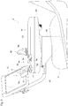
- Fig. 1 illustrates an armrest operation device 4 including an armrest base 40 and a multifunction operation tool 5 swingably supported about a swing axis P1.
- the multifunction operation tool 5 is used to control a work vehicle having a work apparatus and a transmission to change traveling speed, such as a tractor and a front loader.
- the multifunction operation tool 5 substantially includes a grip body 5A and a swing body 5B.
- the swing body 5B is formed as an arm member that swings about the swing axis P1.
- the present embodiment is configured such that causing the swing body 5B to swing in a first direction from a swing neutral position, in which the swing body 5B is substantially vertical, accelerates the vehicle, and causing the swing body 5B to swing in a second direction decelerates the vehicle.
- the grip body 5A is provided on a free end side of the swing body 5B. As illustrated in Fig. 1 , the grip body 5A is configured by a grip part 50 that is formed in a right side area, here substantially a right half area, and an extension part 51 (where operation switch groups 9 are arranged) that is formed in a left side area, here substantially a left half area.
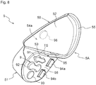
- An outer peripheral surface of the grip body 5A is defined by a convex surface 52, a vertical lateral surface 53, a back surface 54a (see Fig. 7 ), and a bottom surface 54b (see Fig. 7 ).
- the convex surface 52 is shaped so that a palm gripping the grip part 50 easily covers the convex surface 52.
- the vertical lateral surface 53 is a surface which extends substantially perpendicularly with respect to a left edge of the convex surface 52.
- a tongue piece protruding outward is formed as a hypothenar rest 55 on a bottom edge of the grip part 50, that is, on at least a portion of a boundary area between the bottom surface 54b and the convex surface 52.
- the hypothenar rest 55 is shaped to hold the hypothenar of a hand resting on the grip part 50 so that the palm does not slip downward.
- a top surface of the extension part 51 has a surface that is substantially flat or very slightly convex. Because in actual application the top surface of the extension part 51 is arranged so as to face an operator, the extension part 51 is hereafter also referred to as an operator-facing surface 56.
- the operator-facing surface 56 has a shape that extends in a left direction from a bottom edge of the vertical lateral surface 53 of the grip part 50, with the grip part 50 and the extension part 51 connected and the operator-facing surface 56 and the vertical lateral surface 53 intersecting substantially perpendicular to each other.
- a space defined by the operator-facing surface 56 and the vertical lateral surface 53 is large enough that the thumb of the hand resting on the grip part 50 can move freely to a certain extent. For this reason, this space is referred to as a thumb space TS.
- At least one operation switch (including buttons and levers and the like) that belongs to the operation switch groups 9 is arranged on the vertical lateral surface 53 and the operator-facing surface 56.
- the operation switch groups 9 include a travel operation switch group which changes a speed change stage in the transmission and a work operation switch group which controls the work apparatus.
- travel operation switches that belong to the travel operation switch group and work operation switches that belong to the work operation switch group are arranged in an intermingled manner on the operator-facing surface 56.
- Operation switches that belong to the travel operation switch group are arranged on the vertical lateral surface 53, and these operation switches are basically arranged so as to be easily operated with the thumb of the hand resting on the grip part 50.
- Operation switches that belong to the travel operation switch group are also arranged on the back surface 54a of the grip part 50 so as to be easily operated with the middle finger or the index finger of the hand resting on the grip part 50.
- the armrest operation device 4 includes an armrest support base 4A which serves as a mounting base.
- the armrest support base 4A is divided into a front area, a middle area, and a rear area.
- the multifunction operation tool 5 is provided in the front area, and the armrest base 40 on which the operator rests an arm is provided in the rear area.
- An engine control switch group, a work vehicle hydraulic control switch group, and the like are arranged in the front area (other than the installation position of the multifunction operation tool 5) and the middle area.
- the armrest operation device 4 is integrally mounted in an area from a side of a driver's seat of the work vehicle to a front side thereof.
- FIG. 2 is a side view of a tractor that is an example of the work vehicle provided with such an armrest operation device.
- an engine 20 is mounted on a front portion of a vehicle body 1 of the tractor and a transmission 22 is mounted rearward of the engine 20, the vehicle body 1 being supported by front wheels 2a and rear wheels 2b.
- a rotary tilling apparatus as a work apparatus 3 is provided so as to be vertically movable via a link mechanism 30.
- the tractor is a four-wheel-drive vehicle in which the power of the engine 20 is transmitted to the front wheels 2a and the rear wheels 2b via a transmission mechanism for traveling built into the transmission 22. Further, the power of the engine 20 is also transmitted to the work apparatus 3 via a PTO shaft 31 that protrudes rearward from the transmission 22.
- the engine 20 is covered by a hood 21.
- a cabin 10 is supported by the vehicle body 1 rearward of the hood 21 and above the transmission 22.
- An interior of the cabin 10 acts as a driving space.
- a steering handle 11 is provided in a front portion of the driving space to steer the front wheels 2a and a driver's seat 12 is provided in a rear portion of the driving space between a left/right pair of rear wheel fenders 15.
- the armrest operation device 4 having the multifunction operation tool 5 is provided from one side of the driver's seat 12 toward the front thereof.
- a display 13 which visually notifies a driver of various information is provided on a front side of the armrest operation device 4.
- the armrest operation device 4 includes the armrest support base 4A which is fixed to a mounting bracket 4B, the mounting bracket 4B being fixed to a support frame not shown in the drawings.
- a support rod or member 4C which inclines upward while extending forward, is fixed to the mounting bracket 4B, and the display 13 (such as a liquid crystal panel and the like) is mounted on a forefront end of the support rod 4C.
- the display 13 allows an input operation to be performed via a touch panel and can accept various operation inputs by the driver.
- the armrest operation device 4 can be divided into a front area 4a, a middle area 4b, and a rear area 4c in a plan view.
- the cushioned armrest base 40 on which a driver's arm rests is provided in the rear area 4c.
- the multifunction operation tool 5 (described in detail below) is provided in substantially a left half of the front area 4a.
- a first operation switch group 9a and a second operation switch group 9b are arranged as the operation switch groups 9.
- a third operation switch group 9c, a fourth operation switch group 9d, and a fifth operation switch group 9e are arranged as the operation switch groups 9.
- operation switches having various forms such as a button, a switch, a dial, a lever, and a joystick are provided.
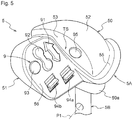
- Figs. 5 through 8 illustrate the multifunction operation tool 5 viewed from various directions.
- the multifunction operation tool 5 is intended for right-hand operation.
- the grip body 5A of the multifunction operation tool 5 is mounted to the swing body 5B that swings about the swing axis P1, the swing axis P1 extending in substantially a transverse direction of the vehicle body 1.
- the swing body 5B is fitted into a bush part 59 formed on the bottom surface 54b of the grip body 5A.
- a skirt 59a is formed around a periphery of a bottom end of the bush part 59.
- the skirt 59a serves as a guide member to a swing port formed on the armrest support base 4A and also as a dust-preventing member.
- the grip body 5A is configured by the grip part 50 and the extension part 51 extending from the left side of the grip part 50.
- the grip part 50 and the extension part 51 are integrally formed.
- a configuration in which the grip part 50 and the extension part 51 are formed separately and then joined together is also possible.
- the grip part 50 in a plan view has a slightly modified 1/8 circle shape, with the top surface of the grip part 50 being the convex surface 52 and the bottom surface 54b being substantially flat.
- the back surface 54a is a substantially flat surface shared with the extension part 51 (see Fig. 7 ).
- the convex surface 52 has a curved shape to accommodate a depression created by a palm when the fingers are bent slightly inward.
- the left lateral surface of the grip part 50 is formed into the substantially flat vertical lateral surface 53.
- the thumb space TS which allows free movement of the thumb is created between the vertical lateral surface 53 and the substantially flat operator-facing surface 56, the operator-facing surface 56 being formed on the top surface of the extension part 51.
- An angle between the vertical lateral surface 53 and the operator-facing surface 56 is approximately 110 degrees.
- a twist angle of the operator-facing surface 56 with respect to the grip part 50 is defined such that the operator-facing surface 56 faces a line of vision of the driver sitting in the driver's seat 12.
- the hypothenar rest 55 protruding in a tongue piece shape is formed from the right bottom edge of the grip part 50 to a boundary edge between the vertical lateral surface 53 and the operator-facing surface 56.
- the protrusion width of the hypothenar rest 55 is wide enough to substantially rest a little finger.
- the transmission 22 has six auxiliary speed change units and four main speed change units, and the main speed change units are speed change units in which impact generated by switching speed change stages is inhibited by appropriate hydraulic control. Twenty-four stages of speed changes are achieved by combining the speed change stages of the auxiliary speed change units and the main speed change units.
- This switching of speed change stages that is, upshift and downshift, is executed by the grip part 50 swinging about the swing axis P1, and ultimately by swinging of the swing body 5B. That is, upshift is executed by displacing the grip part 50 forward while resting the palm on the grip part 50 and downshift is executed by displacing the grip part 50 rearward while resting the palm on the grip part 50.
- a shuttle button 91 and a speed change ratio fixing button 93 that belong to a travel-related operation switch group 9, and an up/down button 92 and two hydraulic control switches 94a and 94b that belong to a work-related operation switch group 9, are provided on the operator-facing surface 56.
- the shuttle button 91 is arranged on substantially an upper half (front half) of the operator-facing surface 56, in a position closest to the vertical lateral surface 53.
- the up/down button 92 is arranged next to the shuttle button 91 on a left side and the speed change ratio fixing button 93 is arranged further left of the shuttle button 91.
- the hydraulic control switches 94a and 94b are arranged side by side on substantially a lower half (front half) of the operator-facing surface 56.
- a speed change auxiliary button 95 is arranged on the vertical lateral surface 53.
- a shuttle auxiliary button 96 is arranged on the back surface 54a of the grip part 50. The shuttle auxiliary button 96 can be easily operated with the index finger or the middle finger of the hand whose palm is resting on the convex surface 52 of the grip part 50.
- the shuttle button 91 switches the transmission 22 to forward travel when an upward arrow portion of the shuttle button 91 is pressed along with the shuttle auxiliary button 96, and switches the transmission 22 to reverse travel when a downward arrow portion of the shuttle button 91 is pressed along with the shuttle auxiliary button 96. That is, forward travel and reverse travel of the tractor can be selected by pressing the shuttle button 91 with the thumb while pressing the shuttle auxiliary button 96 with the middle finger or the index finger (a ring finger or the little finger is also possible).
- the transmission 22 adopted in the present embodiment has main speed change units, in which impact generated by switching speed change stages is inhibited by appropriate hydraulic control, and ordinary synchromesh-type auxiliary speed change units. Therefore, it is preferable that a speed change stage changing operation involving four speed change stages of only the main speed change units without involving the auxiliary speed change units, and a speed change stage changing operation involving the auxiliary speed change units, are each implemented with the difference therebetween in mind.
- the speed change stage changing operation involving only the main speed change units without involving the auxiliary speed change units is enabled even without pressing the speed change auxiliary button 95; however, the speed change stage changing operation involving the auxiliary speed change units is disabled when the speed change auxiliary button 95 is not pressed.
- the speed change stage changing operation involving the auxiliary speed change units must be implemented while pressing the speed change auxiliary button 95. In this instance, the grip part 50 is displaced forward or rearward by the palm while pressing the speed change auxiliary button 95 with the thumb.
- an appropriate speed change ratio according to a vehicle speed can be set by a transmission controller that controls the transmission 22.
- the speed change ratio fixing button 93 is configured as a button that forcibly fixates the speed change ratio and can issue a command to the transmission controller to maintain the speed change ratio of the transmission 22 even when the vehicle speed decreases due to brake operation and the like.
- the up/down button 92 is divided into an upper button and a lower button. Pressing the upper button of the up/down button 92 causes the work apparatus 3 to be lifted and pressing the lower button of the up/down button 92 causes the work apparatus 3 to be lowered.
- the hydraulic control switches 94a and 94b control valves of hydraulic piping connected to the work apparatus 3.
- the present invention can also be applied to various work vehicles including agricultural vehicles such as combines and rice transplanters, and construction vehicles such as front loaders and backhoes.
Claims (12)
- Multifunktionsbedienungswerkzeug (5), das konfiguriert ist, ein Arbeitsfahrzeug mit einer Geschwindigkeitsänderungsfähigkeit zu steuern, das einen Motor (20), Räder (2a, 2b) und ein Getriebe (22) aufweist, das konfiguriert ist, Leistung des Motors (20) zu den Rädern (2a, 2b) zu übertragen;
wobei das Multifunktionsbedienungswerkzeug (5) aufweist:einen Schwenkkörper (5B), der mindestens in eine Längsrichtung eines Fahrzeugaufbaus zum Ausführen einer Beschleunigungssteuerung und Verlangsamungssteuerung schwenkbar gehalten wird;einen Griffkörper (5A), der an einem freien Endabschnitt des Schwenkkörpers (5B) angeordnet ist;einen Griffteil (50), der am Griffkörper (5A) ausgebildet ist und eine konvexe Fläche (52) und eine aufrechte Seitenfläche (53) aufweist,wobei die konvexe Fläche (52) bezüglich einer Querrichtung des Arbeitsfahrzeugs an einem ersten Seitenbereich des Griffkörpers (5A) angeordnet ist, undwobei die aufrechte Seitenfläche (53) bezüglich einer Querrichtung des Arbeitsfahrzeugs an einem zweiten Seitenbereich des Griffkörpers angeordnet ist, der dem ersten Seitenbereich gegenüberliegt;eine zum Bediener weisende Fläche (56), die am zweiten Seitenbereich des Griffkörpers (5A) angeordnet ist und sich von einem Ende der aufrechten Seitenfläche (53) erstreckt; undmindestens einen oder mehrere Bedienungsschalter, die an mindestens einer der aufrechten Seitenfläche (53) und der zum Bediener weisenden Fläche (56) angeordnet sind;dadurch gekennzeichnet, dassder mindestens eine oder die mehreren Bedienungsschalter eine Fahrbetriebsschaltergruppe aufweisen, die einen Kippknopf (91) aufweist, der konfiguriert ist, zwischen einer Vorwärtsfahrt und Rückwärtsfahrt umzuschalten, wobei der Kippknopf (91) auf der zum Bediener weisenden Fläche (56) oder der aufrechten Seitenfläche (53) angeordnet ist;die Fahrbetriebsschaltergruppe ferner einen Freigabekippschalter (96) aufweist, der eine Funktion des Kippknopfes (91) freigibt/sperrt und auf einer bezüglich der aufrechten Seitenfläche (53) gegenüberliegenden Seitenfläche des Griffkörpers (5A) oder auf der Rückseite (54a) des Griffteils (50) angeordnet ist;der Kippknopf (91) konfiguriert ist, das Getriebe (22) in die Vorwärtsfahrt zu schalten, wenn ein Aufwärtspfeilabschnitt des Kippknopfes (91) zusammen mit dem Freigabekippschalter (96) gedrückt wird, und das Getriebe (22) in die Rückwärtsfahrt zu schalten, wenn ein Abwärtspfeilabschnitt des Kippknopfes (91) zusammen mit dem Freigabekippschalter (96) gedrückt wird. - Multifunktionsbedienungswerkzeug nach Anspruch 1, wobei der Kippknopf (91) an einer oberen Hälfte der zum Bediener weisenden Fläche (56) an einer zur vertikalen Seitenfläche (53) nächstgelegenen Position angeordnet ist.
- Multifunktionsbedienungswerkzeug nach einem der Ansprüche 1 bis 2, wobei der Griffteil (50) eine Kleinfingerballenauflage (55) aufweist, die von einem unteren Abschnitt des Griffteils (50) nach außen vorsteht.
- Multifunktionsbedienungswerkzeug nach Anspruch 3, wobei der Griffteil (50) so konfiguriert ist, dass die konvexe Fläche (52) die Handfläche einer Hand eines Bedieners halten kann und die Kleinfingerballenauflage (55) den Kleinfingerballen der Hand des Bedieners halten kann.
- Multifunktionsbedienungswerkzeug nach Anspruch 4, wobei der Griffteil (50) ferner so konfiguriert ist, dass die aufrechte Seitenfläche (53) auf den Daumen der Hand des Bedieners treffen kann.
- Multifunktionsbedienungswerkzeug nach einem der Ansprüche 3 bis 5, wobei sich die Kleinfingerballenauflage (55) von mindestens einem Teil des unteren Rands der konvexen Fläche (52) nach außen erstreckt.
- Multifunktionsbedienungswerkzeug nach einem der Ansprüche 1 bis 6, wobei der mindestens eine oder die mehreren Bedienungsschalter mindestens einen aufweisen von:einen Fahrbetriebsschalter, der mit einem Getriebe (22) des Arbeitsfahrzeugs gekoppelt ist oder dessen Steuerung bereitstellt;einen Arbeitsbetriebsschalter, der mit einer Arbeitsvorrichtung des Arbeitsfahrzeugs gekoppelt ist oder deren Steuerung bereitstellt; undmindestens einen Fahrbetriebsschalter und mindestens einen Arbeitsbetriebsschalter, die auf der zum Bediener weisenden Fläche (56) angeordnet sind.
- Multifunktionsbedienungswerkzeug nach einem der Ansprüche 1 bis 7, wobei der Griffteil (50) bezüglich der Querrichtung des Fahrzeugaufbaus zu der zum Bediener weisenden Fläche (56) benachbart ist.
- Multifunktionsbedienungswerkzeug nach einem der Ansprüche 1 bis 8, wobei der Griffteil (50) und die zum Bediener weisende Fläche (56) so angeordnet sind, dass sie einen Höhenunterschied der Oberseiten bilden.
- Multifunktionsbedienungswerkzeug nach einem der Ansprüche 1 bis 9, wobei die aufrechte Seitenfläche (53) so angeordnet ist, dass sie die Oberseiten des Griffteils (50) und der zum Bediener weisenden Fläche (56) verbindet.
- Armlehnen-Bedienungsvorrichtung, die aufweist:das Multifunktionsbedienungswerkzeug nach einem der Ansprüche 1 bis 10; undeine Armlehnen-Grundträger, der einen vorderen Bereich, einen mittleren Bereich und einen hinteren Bereich aufweist, die in eine Längsrichtung des Fahrzeugaufbaus ausgerichtet sind,wobei das Multifunktionsbedienungswerkzeug im vorderen Bereich angeordnet ist und der mittlere Bereich eine motorsteuerschaltergruppe und eine Arbeitsfahrzeug-Hydrauliksteuerschaltergruppe aufweist.
- Arbeitsfahrzeug, das aufweist:einen Motor (20);Räder (2a, 2b);ein Getriebe (22), das konfiguriert ist, Leistung des Motors (20) zu den Rädern (2a, 2b) zu übertragen; undeine Multifunktionsbedienungswerkzeug (5) nach einem der Ansprüche 1 bis 10.
Applications Claiming Priority (2)
| Application Number | Priority Date | Filing Date | Title |
|---|---|---|---|
| JP2014140589A JP6317202B2 (ja) | 2014-07-08 | 2014-07-08 | 多機能操作具及びアームレスト操作装置 |
| EP15161510.1A EP2965937B1 (de) | 2014-07-08 | 2015-03-27 | Multifunktions-Bedienungswerkzeug und Armlehne Betriebseinrichtung |
Related Parent Applications (2)
| Application Number | Title | Priority Date | Filing Date |
|---|---|---|---|
| EP15161510.1A Division EP2965937B1 (de) | 2014-07-08 | 2015-03-27 | Multifunktions-Bedienungswerkzeug und Armlehne Betriebseinrichtung |
| EP15161510.1A Division-Into EP2965937B1 (de) | 2014-07-08 | 2015-03-27 | Multifunktions-Bedienungswerkzeug und Armlehne Betriebseinrichtung |
Publications (3)
| Publication Number | Publication Date |
|---|---|
| EP3132964A2 EP3132964A2 (de) | 2017-02-22 |
| EP3132964A3 EP3132964A3 (de) | 2017-03-29 |
| EP3132964B1 true EP3132964B1 (de) | 2019-10-02 |
Family
ID=52780922
Family Applications (3)
| Application Number | Title | Priority Date | Filing Date |
|---|---|---|---|
| EP15161510.1A Active EP2965937B1 (de) | 2014-07-08 | 2015-03-27 | Multifunktions-Bedienungswerkzeug und Armlehne Betriebseinrichtung |
| EP16193594.5A Active EP3132964B1 (de) | 2014-07-08 | 2015-03-27 | Multifunktionsbetriebswerkzeug, armlehnenbetriebsvorrichtung und arbeitsfahrzeug |
| EP16193595.2A Active EP3132963B1 (de) | 2014-07-08 | 2015-03-27 | Nutzfahrzeug |
Family Applications Before (1)
| Application Number | Title | Priority Date | Filing Date |
|---|---|---|---|
| EP15161510.1A Active EP2965937B1 (de) | 2014-07-08 | 2015-03-27 | Multifunktions-Bedienungswerkzeug und Armlehne Betriebseinrichtung |
Family Applications After (1)
| Application Number | Title | Priority Date | Filing Date |
|---|---|---|---|
| EP16193595.2A Active EP3132963B1 (de) | 2014-07-08 | 2015-03-27 | Nutzfahrzeug |
Country Status (3)
| Country | Link |
|---|---|
| US (1) | US9315103B2 (de) |
| EP (3) | EP2965937B1 (de) |
| JP (1) | JP6317202B2 (de) |
Families Citing this family (30)
| Publication number | Priority date | Publication date | Assignee | Title |
|---|---|---|---|---|
| DE102013012176A1 (de) * | 2013-07-22 | 2015-01-22 | Jungheinrich Aktiengesellschaft | Bedienelement für ein Flurförderzeug |
| CN105452976B (zh) * | 2013-08-09 | 2017-09-01 | 洋马株式会社 | 作业车辆 |
| KR101565047B1 (ko) * | 2014-08-12 | 2015-11-02 | 현대자동차주식회사 | 스티어링 휠 및 악셀 페달 통합 구조를 갖는 컨트롤 보드 |
| WO2017024008A1 (en) * | 2015-08-03 | 2017-02-09 | Clark Equipment Company | Joystick controller for power machine |
| USD771152S1 (en) * | 2015-09-02 | 2016-11-08 | The Charles Machine Works, Inc. | Joystick |
| USD777803S1 (en) * | 2015-10-22 | 2017-01-31 | Deere & Company | Control device |
| EP3411325B1 (de) | 2016-02-05 | 2022-09-28 | Crown Equipment Corporation | Steuerungselemente für materialhandhabungsfahrzeuge |
| WO2017141420A1 (ja) * | 2016-02-19 | 2017-08-24 | 株式会社小松製作所 | 作業車両の操作装置 |
| JP6517724B2 (ja) * | 2016-04-08 | 2019-05-22 | ミネベアミツミ株式会社 | 面状照明装置 |
| GB201617661D0 (en) | 2016-10-19 | 2016-11-30 | Agco International Gmbh | A control lever for a vehicle |
| KR102375140B1 (ko) * | 2017-05-10 | 2022-03-16 | 현대자동차주식회사 | 차량용 변속 레버 장치 |
| US20180363272A1 (en) * | 2017-06-20 | 2018-12-20 | KUBOTA DEUTSCHLAND GmbH | Working machine |
| JP6410162B1 (ja) * | 2017-07-24 | 2018-10-24 | 有限会社 波多野巌松堂書店 | 運転支援装置、運転支援方法およびプログラム |
| US10691157B2 (en) | 2017-11-24 | 2020-06-23 | Komatsu Ltd. | Operation lever and work vehicle |
| EP3815983A4 (de) * | 2018-06-29 | 2022-03-09 | Kubota Corporation | Arbeitsmaschine |
| US10591948B1 (en) * | 2018-08-30 | 2020-03-17 | Essex Industries, Inc. | Collective control system for a rotorcraft |
| KR20210039455A (ko) * | 2018-08-30 | 2021-04-09 | 에섹스 인더스트리스, 아이엔씨. | 회전익기용 콜렉티브 제어 시스템 |
| JP7163158B2 (ja) * | 2018-12-06 | 2022-10-31 | 株式会社クボタ | 作業車両の操作レバー及び作業車両 |
| JP7126933B2 (ja) * | 2018-12-06 | 2022-08-29 | 株式会社クボタ | 作業車両 |
| JP7126934B2 (ja) * | 2018-12-06 | 2022-08-29 | 株式会社クボタ | 作業車両の操作レバー及び作業車両 |
| JP7346251B2 (ja) * | 2018-12-06 | 2023-09-19 | 株式会社クボタ | 作業車両の操作レバー及び作業車両 |
| EP3663128B1 (de) | 2018-12-06 | 2023-10-04 | Kubota Corporation | Nutzfahrzeug |
| US11314274B2 (en) | 2018-12-06 | 2022-04-26 | Kubota Corporation | Operation lever for working vehicle and working vehicle |
| JP7433845B2 (ja) * | 2018-12-06 | 2024-02-20 | 株式会社クボタ | 作業車両 |
| JP7226096B2 (ja) | 2019-05-24 | 2023-02-21 | マツダ株式会社 | 車両の制御装置 |
| EP3819154B1 (de) | 2019-11-08 | 2022-10-12 | Kubota Corporation | Nutzfahrzeug |
| JP7366697B2 (ja) * | 2019-11-08 | 2023-10-23 | 株式会社クボタ | 作業車両 |
| JP7275006B2 (ja) * | 2019-11-08 | 2023-05-17 | 株式会社クボタ | 作業車両 |
| US11866909B2 (en) * | 2020-11-04 | 2024-01-09 | Caterpillar Inc. | Machine control component with input device to control machine display |
| WO2023127735A1 (ja) * | 2021-12-28 | 2023-07-06 | 株式会社クボタ | 操作装置および作業車両 |
Family Cites Families (20)
| Publication number | Priority date | Publication date | Assignee | Title |
|---|---|---|---|---|
| DE4341834C1 (de) | 1993-12-08 | 1995-04-20 | Claas Ohg | Landmaschine, insbesondere Mähdrescher, mit Multiprozessor-Leitvorrichtung |
| EP0943976B1 (de) | 1994-11-08 | 2001-10-04 | Jungheinrich Aktiengesellschaft | Handbetätigte Stellvorrichtung für einen Bedienungsstand bzw. -sitz |
| DE19624463A1 (de) | 1996-06-19 | 1998-01-02 | Fendt Xaver Gmbh & Co | Steuereinrichtung für Nutzfahrzeuge, insbesondere für landwirtschaftliche nutzbare Schlepper |
| US5924515A (en) | 1997-03-17 | 1999-07-20 | New Holland North America, Inc. | Operator seat sliding control console |
| FR2776968B1 (fr) * | 1998-04-06 | 2000-05-26 | Renault Agriculture | Console ergonomique de commande pour un vehicule utilitaire |
| US6148593A (en) | 1998-06-17 | 2000-11-21 | New Holland North America, Inc. | Multifunctional handle for controlling an agricultural combine |
| JP2000071801A (ja) * | 1998-06-19 | 2000-03-07 | Komatsu Ltd | 作業車両の操向操作レバ― |
| JP2002073187A (ja) * | 2000-09-01 | 2002-03-12 | Komatsu Ltd | 作業車両の操縦装置 |
| DE10140975A1 (de) | 2001-08-27 | 2003-03-20 | Claas Selbstfahr Erntemasch | Vorrichtung zum Steuern eines landwirtschaftlichen Fahrzeugs |
| JP2003184132A (ja) * | 2001-12-25 | 2003-07-03 | Hitachi Constr Mach Co Ltd | 建設機械の操作レバー装置 |
| DE10350407A1 (de) | 2003-10-28 | 2005-05-25 | Deere & Company, Moline | Vorrichtung zum Bedienen eines Fahrzeugs |
| US7178623B2 (en) | 2003-12-19 | 2007-02-20 | Caterpillar Inc | Operator control assembly |
| DE102006018537B4 (de) | 2006-04-21 | 2013-11-07 | Grammer Aktiengesellschaft | Steuerkonsole an einer Armlehne eines Fahrzeugsitzes |
| US20090139360A1 (en) * | 2007-11-30 | 2009-06-04 | Caterpillar Inc | Joystick attachment |
| DE102008044174A1 (de) | 2008-11-28 | 2010-06-02 | Deere & Company, Moline | Bediensystem für ein Kraftfahrzeug |
| DE102009034154A1 (de) | 2009-07-20 | 2011-02-03 | Claas Selbstfahrende Erntemaschinen Gmbh | Multifunktionsgriff |
| JP5602604B2 (ja) * | 2010-12-02 | 2014-10-08 | 三菱農機株式会社 | 作業用走行車の変速操作具 |
| JP2012139133A (ja) * | 2010-12-28 | 2012-07-26 | Mitsubishi Agricultural Machinery Co Ltd | 乗用移植機 |
| FI123894B (fi) | 2011-02-25 | 2013-12-13 | Ponsse Oyj | Ohjainväline |
| US8770887B1 (en) * | 2013-01-18 | 2014-07-08 | Waacker Neuson Production Americas LLC | Vibratory compacting roller machine and operator control therefor |
-
2014
- 2014-07-08 JP JP2014140589A patent/JP6317202B2/ja active Active
-
2015
- 2015-03-20 US US14/664,004 patent/US9315103B2/en active Active
- 2015-03-27 EP EP15161510.1A patent/EP2965937B1/de active Active
- 2015-03-27 EP EP16193594.5A patent/EP3132964B1/de active Active
- 2015-03-27 EP EP16193595.2A patent/EP3132963B1/de active Active
Non-Patent Citations (1)
| Title |
|---|
| None * |
Also Published As
| Publication number | Publication date |
|---|---|
| EP3132964A2 (de) | 2017-02-22 |
| US9315103B2 (en) | 2016-04-19 |
| EP3132963A3 (de) | 2017-03-29 |
| EP2965937A1 (de) | 2016-01-13 |
| EP3132963A2 (de) | 2017-02-22 |
| EP2965937B1 (de) | 2017-06-21 |
| US20160009174A1 (en) | 2016-01-14 |
| EP3132964A3 (de) | 2017-03-29 |
| JP6317202B2 (ja) | 2018-04-25 |
| JP2016016739A (ja) | 2016-02-01 |
| EP3132963B1 (de) | 2019-07-10 |
Similar Documents
| Publication | Publication Date | Title |
|---|---|---|
| EP3132964B1 (de) | Multifunktionsbetriebswerkzeug, armlehnenbetriebsvorrichtung und arbeitsfahrzeug | |
| JP6234342B2 (ja) | 操作制御システム | |
| US20050034549A1 (en) | Device for interactive control with the hand of an operator | |
| WO2015019943A1 (ja) | 作業車両 | |
| US9725090B2 (en) | Speed control for working vehicle | |
| KR20120033219A (ko) | 작업차 | |
| EP2965938B1 (de) | Drehzahlregelung für arbeitsfahrzeug | |
| JP6305265B2 (ja) | 走行作業車 | |
| US11573591B2 (en) | Machine joystick with ergonomic features | |
| US11414832B2 (en) | Work vehicle | |
| JP6843199B2 (ja) | 作業車 | |
| JP6584566B2 (ja) | 多機能操作具、アームレスト操作装置、及び作業車 | |
| JP4245410B2 (ja) | 田植機の操作スイッチ | |
| US11614766B2 (en) | Machine joystick with comfort and accessibility features | |
| WO2023100602A1 (ja) | キャブ及び作業機械 | |
| JP2007011495A (ja) | 作業車の操作部 | |
| USH1908H (en) | Lever bank for heavy vehicle | |
| JP3653020B2 (ja) | 建設機械の操作レバー装置 | |
| CN117739109A (zh) | 作业车辆 | |
| JPS62100212A (ja) | コンバインにおける操作装置 | |
| JP2018020744A (ja) | トラクタ | |
| JPH10291429A (ja) | トラクタの変速操作装置 | |
| JPH10278617A (ja) | トラクタの変速操作装置 | |
| JPH10324168A (ja) | 走行車両の操作部材 | |
| JP2012003640A (ja) | 農業用トラクタ |
Legal Events
| Date | Code | Title | Description |
|---|---|---|---|
| PUAI | Public reference made under article 153(3) epc to a published international application that has entered the european phase |
Free format text: ORIGINAL CODE: 0009012 |
|
| STAA | Information on the status of an ep patent application or granted ep patent |
Free format text: STATUS: THE APPLICATION HAS BEEN PUBLISHED |
|
| AC | Divisional application: reference to earlier application |
Ref document number: 2965937 Country of ref document: EP Kind code of ref document: P |
|
| AK | Designated contracting states |
Kind code of ref document: A2 Designated state(s): AL AT BE BG CH CY CZ DE DK EE ES FI FR GB GR HR HU IE IS IT LI LT LU LV MC MK MT NL NO PL PT RO RS SE SI SK SM TR |
|
| PUAL | Search report despatched |
Free format text: ORIGINAL CODE: 0009013 |
|
| AK | Designated contracting states |
Kind code of ref document: A3 Designated state(s): AL AT BE BG CH CY CZ DE DK EE ES FI FR GB GR HR HU IE IS IT LI LT LU LV MC MK MT NL NO PL PT RO RS SE SI SK SM TR |
|
| RIC1 | Information provided on ipc code assigned before grant |
Ipc: B60W 30/18 20120101ALI20170222BHEP Ipc: B60K 26/02 20060101AFI20170222BHEP Ipc: B60W 30/14 20060101ALI20170222BHEP |
|
| STAA | Information on the status of an ep patent application or granted ep patent |
Free format text: STATUS: REQUEST FOR EXAMINATION WAS MADE |
|
| 17P | Request for examination filed |
Effective date: 20170829 |
|
| RBV | Designated contracting states (corrected) |
Designated state(s): AL AT BE BG CH CY CZ DE DK EE ES FI FR GB GR HR HU IE IS IT LI LT LU LV MC MK MT NL NO PL PT RO RS SE SI SK SM TR |
|
| GRAP | Despatch of communication of intention to grant a patent |
Free format text: ORIGINAL CODE: EPIDOSNIGR1 |
|
| STAA | Information on the status of an ep patent application or granted ep patent |
Free format text: STATUS: GRANT OF PATENT IS INTENDED |
|
| INTG | Intention to grant announced |
Effective date: 20190604 |
|
| GRAS | Grant fee paid |
Free format text: ORIGINAL CODE: EPIDOSNIGR3 |
|
| GRAA | (expected) grant |
Free format text: ORIGINAL CODE: 0009210 |
|
| STAA | Information on the status of an ep patent application or granted ep patent |
Free format text: STATUS: THE PATENT HAS BEEN GRANTED |
|
| AC | Divisional application: reference to earlier application |
Ref document number: 2965937 Country of ref document: EP Kind code of ref document: P |
|
| AK | Designated contracting states |
Kind code of ref document: B1 Designated state(s): AL AT BE BG CH CY CZ DE DK EE ES FI FR GB GR HR HU IE IS IT LI LT LU LV MC MK MT NL NO PL PT RO RS SE SI SK SM TR |
|
| REG | Reference to a national code |
Ref country code: GB Ref legal event code: FG4D |
|
| REG | Reference to a national code |
Ref country code: CH Ref legal event code: EP Ref country code: AT Ref legal event code: REF Ref document number: 1185806 Country of ref document: AT Kind code of ref document: T Effective date: 20191015 |
|
| REG | Reference to a national code |
Ref country code: DE Ref legal event code: R096 Ref document number: 602015039316 Country of ref document: DE |
|
| REG | Reference to a national code |
Ref country code: IE Ref legal event code: FG4D |
|
| REG | Reference to a national code |
Ref country code: NL Ref legal event code: MP Effective date: 20191002 |
|
| REG | Reference to a national code |
Ref country code: LT Ref legal event code: MG4D |
|
| REG | Reference to a national code |
Ref country code: AT Ref legal event code: MK05 Ref document number: 1185806 Country of ref document: AT Kind code of ref document: T Effective date: 20191002 |
|
| PG25 | Lapsed in a contracting state [announced via postgrant information from national office to epo] |
Ref country code: LT Free format text: LAPSE BECAUSE OF FAILURE TO SUBMIT A TRANSLATION OF THE DESCRIPTION OR TO PAY THE FEE WITHIN THE PRESCRIBED TIME-LIMIT Effective date: 20191002 Ref country code: NL Free format text: LAPSE BECAUSE OF FAILURE TO SUBMIT A TRANSLATION OF THE DESCRIPTION OR TO PAY THE FEE WITHIN THE PRESCRIBED TIME-LIMIT Effective date: 20191002 Ref country code: BG Free format text: LAPSE BECAUSE OF FAILURE TO SUBMIT A TRANSLATION OF THE DESCRIPTION OR TO PAY THE FEE WITHIN THE PRESCRIBED TIME-LIMIT Effective date: 20200102 Ref country code: SE Free format text: LAPSE BECAUSE OF FAILURE TO SUBMIT A TRANSLATION OF THE DESCRIPTION OR TO PAY THE FEE WITHIN THE PRESCRIBED TIME-LIMIT Effective date: 20191002 Ref country code: PT Free format text: LAPSE BECAUSE OF FAILURE TO SUBMIT A TRANSLATION OF THE DESCRIPTION OR TO PAY THE FEE WITHIN THE PRESCRIBED TIME-LIMIT Effective date: 20200203 Ref country code: FI Free format text: LAPSE BECAUSE OF FAILURE TO SUBMIT A TRANSLATION OF THE DESCRIPTION OR TO PAY THE FEE WITHIN THE PRESCRIBED TIME-LIMIT Effective date: 20191002 Ref country code: AT Free format text: LAPSE BECAUSE OF FAILURE TO SUBMIT A TRANSLATION OF THE DESCRIPTION OR TO PAY THE FEE WITHIN THE PRESCRIBED TIME-LIMIT Effective date: 20191002 Ref country code: LV Free format text: LAPSE BECAUSE OF FAILURE TO SUBMIT A TRANSLATION OF THE DESCRIPTION OR TO PAY THE FEE WITHIN THE PRESCRIBED TIME-LIMIT Effective date: 20191002 Ref country code: ES Free format text: LAPSE BECAUSE OF FAILURE TO SUBMIT A TRANSLATION OF THE DESCRIPTION OR TO PAY THE FEE WITHIN THE PRESCRIBED TIME-LIMIT Effective date: 20191002 Ref country code: NO Free format text: LAPSE BECAUSE OF FAILURE TO SUBMIT A TRANSLATION OF THE DESCRIPTION OR TO PAY THE FEE WITHIN THE PRESCRIBED TIME-LIMIT Effective date: 20200102 Ref country code: GR Free format text: LAPSE BECAUSE OF FAILURE TO SUBMIT A TRANSLATION OF THE DESCRIPTION OR TO PAY THE FEE WITHIN THE PRESCRIBED TIME-LIMIT Effective date: 20200103 Ref country code: PL Free format text: LAPSE BECAUSE OF FAILURE TO SUBMIT A TRANSLATION OF THE DESCRIPTION OR TO PAY THE FEE WITHIN THE PRESCRIBED TIME-LIMIT Effective date: 20191002 |
|
| PG25 | Lapsed in a contracting state [announced via postgrant information from national office to epo] |
Ref country code: IS Free format text: LAPSE BECAUSE OF FAILURE TO SUBMIT A TRANSLATION OF THE DESCRIPTION OR TO PAY THE FEE WITHIN THE PRESCRIBED TIME-LIMIT Effective date: 20200224 Ref country code: RS Free format text: LAPSE BECAUSE OF FAILURE TO SUBMIT A TRANSLATION OF THE DESCRIPTION OR TO PAY THE FEE WITHIN THE PRESCRIBED TIME-LIMIT Effective date: 20191002 Ref country code: HR Free format text: LAPSE BECAUSE OF FAILURE TO SUBMIT A TRANSLATION OF THE DESCRIPTION OR TO PAY THE FEE WITHIN THE PRESCRIBED TIME-LIMIT Effective date: 20191002 Ref country code: CZ Free format text: LAPSE BECAUSE OF FAILURE TO SUBMIT A TRANSLATION OF THE DESCRIPTION OR TO PAY THE FEE WITHIN THE PRESCRIBED TIME-LIMIT Effective date: 20191002 |
|
| PG25 | Lapsed in a contracting state [announced via postgrant information from national office to epo] |
Ref country code: AL Free format text: LAPSE BECAUSE OF FAILURE TO SUBMIT A TRANSLATION OF THE DESCRIPTION OR TO PAY THE FEE WITHIN THE PRESCRIBED TIME-LIMIT Effective date: 20191002 |
|
| REG | Reference to a national code |
Ref country code: DE Ref legal event code: R097 Ref document number: 602015039316 Country of ref document: DE |
|
| PG2D | Information on lapse in contracting state deleted |
Ref country code: IS |
|
| PG25 | Lapsed in a contracting state [announced via postgrant information from national office to epo] |
Ref country code: RO Free format text: LAPSE BECAUSE OF FAILURE TO SUBMIT A TRANSLATION OF THE DESCRIPTION OR TO PAY THE FEE WITHIN THE PRESCRIBED TIME-LIMIT Effective date: 20191002 Ref country code: EE Free format text: LAPSE BECAUSE OF FAILURE TO SUBMIT A TRANSLATION OF THE DESCRIPTION OR TO PAY THE FEE WITHIN THE PRESCRIBED TIME-LIMIT Effective date: 20191002 Ref country code: DK Free format text: LAPSE BECAUSE OF FAILURE TO SUBMIT A TRANSLATION OF THE DESCRIPTION OR TO PAY THE FEE WITHIN THE PRESCRIBED TIME-LIMIT Effective date: 20191002 Ref country code: IS Free format text: LAPSE BECAUSE OF FAILURE TO SUBMIT A TRANSLATION OF THE DESCRIPTION OR TO PAY THE FEE WITHIN THE PRESCRIBED TIME-LIMIT Effective date: 20200202 |
|
| PLBE | No opposition filed within time limit |
Free format text: ORIGINAL CODE: 0009261 |
|
| STAA | Information on the status of an ep patent application or granted ep patent |
Free format text: STATUS: NO OPPOSITION FILED WITHIN TIME LIMIT |
|
| PG25 | Lapsed in a contracting state [announced via postgrant information from national office to epo] |
Ref country code: SM Free format text: LAPSE BECAUSE OF FAILURE TO SUBMIT A TRANSLATION OF THE DESCRIPTION OR TO PAY THE FEE WITHIN THE PRESCRIBED TIME-LIMIT Effective date: 20191002 Ref country code: SK Free format text: LAPSE BECAUSE OF FAILURE TO SUBMIT A TRANSLATION OF THE DESCRIPTION OR TO PAY THE FEE WITHIN THE PRESCRIBED TIME-LIMIT Effective date: 20191002 Ref country code: IT Free format text: LAPSE BECAUSE OF FAILURE TO SUBMIT A TRANSLATION OF THE DESCRIPTION OR TO PAY THE FEE WITHIN THE PRESCRIBED TIME-LIMIT Effective date: 20191002 |
|
| 26N | No opposition filed |
Effective date: 20200703 |
|
| REG | Reference to a national code |
Ref country code: DE Ref legal event code: R119 Ref document number: 602015039316 Country of ref document: DE |
|
| PG25 | Lapsed in a contracting state [announced via postgrant information from national office to epo] |
Ref country code: MC Free format text: LAPSE BECAUSE OF FAILURE TO SUBMIT A TRANSLATION OF THE DESCRIPTION OR TO PAY THE FEE WITHIN THE PRESCRIBED TIME-LIMIT Effective date: 20191002 |
|
| REG | Reference to a national code |
Ref country code: CH Ref legal event code: PL |
|
| PG25 | Lapsed in a contracting state [announced via postgrant information from national office to epo] |
Ref country code: SI Free format text: LAPSE BECAUSE OF FAILURE TO SUBMIT A TRANSLATION OF THE DESCRIPTION OR TO PAY THE FEE WITHIN THE PRESCRIBED TIME-LIMIT Effective date: 20191002 |
|
| REG | Reference to a national code |
Ref country code: BE Ref legal event code: MM Effective date: 20200331 |
|
| PG25 | Lapsed in a contracting state [announced via postgrant information from national office to epo] |
Ref country code: LU Free format text: LAPSE BECAUSE OF NON-PAYMENT OF DUE FEES Effective date: 20200327 |
|
| PG25 | Lapsed in a contracting state [announced via postgrant information from national office to epo] |
Ref country code: LI Free format text: LAPSE BECAUSE OF NON-PAYMENT OF DUE FEES Effective date: 20200331 Ref country code: IE Free format text: LAPSE BECAUSE OF NON-PAYMENT OF DUE FEES Effective date: 20200327 Ref country code: DE Free format text: LAPSE BECAUSE OF NON-PAYMENT OF DUE FEES Effective date: 20201001 Ref country code: CH Free format text: LAPSE BECAUSE OF NON-PAYMENT OF DUE FEES Effective date: 20200331 |
|
| PG25 | Lapsed in a contracting state [announced via postgrant information from national office to epo] |
Ref country code: BE Free format text: LAPSE BECAUSE OF NON-PAYMENT OF DUE FEES Effective date: 20200331 |
|
| GBPC | Gb: european patent ceased through non-payment of renewal fee |
Effective date: 20200327 |
|
| PG25 | Lapsed in a contracting state [announced via postgrant information from national office to epo] |
Ref country code: GB Free format text: LAPSE BECAUSE OF NON-PAYMENT OF DUE FEES Effective date: 20200327 |
|
| PG25 | Lapsed in a contracting state [announced via postgrant information from national office to epo] |
Ref country code: TR Free format text: LAPSE BECAUSE OF FAILURE TO SUBMIT A TRANSLATION OF THE DESCRIPTION OR TO PAY THE FEE WITHIN THE PRESCRIBED TIME-LIMIT Effective date: 20191002 Ref country code: MT Free format text: LAPSE BECAUSE OF FAILURE TO SUBMIT A TRANSLATION OF THE DESCRIPTION OR TO PAY THE FEE WITHIN THE PRESCRIBED TIME-LIMIT Effective date: 20191002 Ref country code: CY Free format text: LAPSE BECAUSE OF FAILURE TO SUBMIT A TRANSLATION OF THE DESCRIPTION OR TO PAY THE FEE WITHIN THE PRESCRIBED TIME-LIMIT Effective date: 20191002 |
|
| PG25 | Lapsed in a contracting state [announced via postgrant information from national office to epo] |
Ref country code: MK Free format text: LAPSE BECAUSE OF FAILURE TO SUBMIT A TRANSLATION OF THE DESCRIPTION OR TO PAY THE FEE WITHIN THE PRESCRIBED TIME-LIMIT Effective date: 20191002 |
|
| PGFP | Annual fee paid to national office [announced via postgrant information from national office to epo] |
Ref country code: FR Payment date: 20230208 Year of fee payment: 9 |