EP3129672B2 - Scheibenbremsbelag, feder für scheibenbremszange und scheibenbremszangenanordnung - Google Patents
Scheibenbremsbelag, feder für scheibenbremszange und scheibenbremszangenanordnung Download PDFInfo
- Publication number
- EP3129672B2 EP3129672B2 EP15721858.7A EP15721858A EP3129672B2 EP 3129672 B2 EP3129672 B2 EP 3129672B2 EP 15721858 A EP15721858 A EP 15721858A EP 3129672 B2 EP3129672 B2 EP 3129672B2
- Authority
- EP
- European Patent Office
- Prior art keywords
- pad
- spring
- thrust
- caliper
- brake
- Prior art date
- Legal status (The legal status is an assumption and is not a legal conclusion. Google has not performed a legal analysis and makes no representation as to the accuracy of the status listed.)
- Active
Links
Images


Classifications
-
- F—MECHANICAL ENGINEERING; LIGHTING; HEATING; WEAPONS; BLASTING
- F16—ENGINEERING ELEMENTS AND UNITS; GENERAL MEASURES FOR PRODUCING AND MAINTAINING EFFECTIVE FUNCTIONING OF MACHINES OR INSTALLATIONS; THERMAL INSULATION IN GENERAL
- F16D—COUPLINGS FOR TRANSMITTING ROTATION; CLUTCHES; BRAKES
- F16D65/00—Parts or details
- F16D65/02—Braking members; Mounting thereof
- F16D65/04—Bands, shoes or pads; Pivots or supporting members therefor
- F16D65/092—Bands, shoes or pads; Pivots or supporting members therefor for axially-engaging brakes, e.g. disc brakes
- F16D65/095—Pivots or supporting members therefor
- F16D65/097—Resilient means interposed between pads and supporting members or other brake parts
- F16D65/0973—Resilient means interposed between pads and supporting members or other brake parts not subjected to brake forces
- F16D65/0974—Resilient means interposed between pads and supporting members or other brake parts not subjected to brake forces acting on or in the vicinity of the pad rim in a direction substantially transverse to the brake disc axis
- F16D65/0977—Springs made from sheet metal
-
- F—MECHANICAL ENGINEERING; LIGHTING; HEATING; WEAPONS; BLASTING
- F16—ENGINEERING ELEMENTS AND UNITS; GENERAL MEASURES FOR PRODUCING AND MAINTAINING EFFECTIVE FUNCTIONING OF MACHINES OR INSTALLATIONS; THERMAL INSULATION IN GENERAL
- F16D—COUPLINGS FOR TRANSMITTING ROTATION; CLUTCHES; BRAKES
- F16D55/00—Brakes with substantially-radial braking surfaces pressed together in axial direction, e.g. disc brakes
- F16D55/02—Brakes with substantially-radial braking surfaces pressed together in axial direction, e.g. disc brakes with axially-movable discs or pads pressed against axially-located rotating members
- F16D55/22—Brakes with substantially-radial braking surfaces pressed together in axial direction, e.g. disc brakes with axially-movable discs or pads pressed against axially-located rotating members by clamping an axially-located rotating disc between movable braking members, e.g. movable brake discs or brake pads
- F16D55/224—Brakes with substantially-radial braking surfaces pressed together in axial direction, e.g. disc brakes with axially-movable discs or pads pressed against axially-located rotating members by clamping an axially-located rotating disc between movable braking members, e.g. movable brake discs or brake pads with a common actuating member for the braking members
- F16D55/225—Brakes with substantially-radial braking surfaces pressed together in axial direction, e.g. disc brakes with axially-movable discs or pads pressed against axially-located rotating members by clamping an axially-located rotating disc between movable braking members, e.g. movable brake discs or brake pads with a common actuating member for the braking members the braking members being brake pads
- F16D55/226—Brakes with substantially-radial braking surfaces pressed together in axial direction, e.g. disc brakes with axially-movable discs or pads pressed against axially-located rotating members by clamping an axially-located rotating disc between movable braking members, e.g. movable brake discs or brake pads with a common actuating member for the braking members the braking members being brake pads in which the common actuating member is moved axially, e.g. floating caliper disc brakes
- F16D55/2265—Brakes with substantially-radial braking surfaces pressed together in axial direction, e.g. disc brakes with axially-movable discs or pads pressed against axially-located rotating members by clamping an axially-located rotating disc between movable braking members, e.g. movable brake discs or brake pads with a common actuating member for the braking members the braking members being brake pads in which the common actuating member is moved axially, e.g. floating caliper disc brakes the axial movement being guided by one or more pins engaging bores in the brake support or the brake housing
-
- F—MECHANICAL ENGINEERING; LIGHTING; HEATING; WEAPONS; BLASTING
- F16—ENGINEERING ELEMENTS AND UNITS; GENERAL MEASURES FOR PRODUCING AND MAINTAINING EFFECTIVE FUNCTIONING OF MACHINES OR INSTALLATIONS; THERMAL INSULATION IN GENERAL
- F16D—COUPLINGS FOR TRANSMITTING ROTATION; CLUTCHES; BRAKES
- F16D65/00—Parts or details
- F16D65/0006—Noise or vibration control
-
- F—MECHANICAL ENGINEERING; LIGHTING; HEATING; WEAPONS; BLASTING
- F16—ENGINEERING ELEMENTS AND UNITS; GENERAL MEASURES FOR PRODUCING AND MAINTAINING EFFECTIVE FUNCTIONING OF MACHINES OR INSTALLATIONS; THERMAL INSULATION IN GENERAL
- F16D—COUPLINGS FOR TRANSMITTING ROTATION; CLUTCHES; BRAKES
- F16D65/00—Parts or details
- F16D65/02—Braking members; Mounting thereof
- F16D65/04—Bands, shoes or pads; Pivots or supporting members therefor
- F16D65/092—Bands, shoes or pads; Pivots or supporting members therefor for axially-engaging brakes, e.g. disc brakes
- F16D65/095—Pivots or supporting members therefor
- F16D65/097—Resilient means interposed between pads and supporting members or other brake parts
- F16D65/0971—Resilient means interposed between pads and supporting members or other brake parts transmitting brake actuation force, e.g. elements interposed between brake piston and pad
-
- F—MECHANICAL ENGINEERING; LIGHTING; HEATING; WEAPONS; BLASTING
- F16—ENGINEERING ELEMENTS AND UNITS; GENERAL MEASURES FOR PRODUCING AND MAINTAINING EFFECTIVE FUNCTIONING OF MACHINES OR INSTALLATIONS; THERMAL INSULATION IN GENERAL
- F16D—COUPLINGS FOR TRANSMITTING ROTATION; CLUTCHES; BRAKES
- F16D65/00—Parts or details
- F16D65/02—Braking members; Mounting thereof
- F16D65/12—Discs; Drums for disc brakes
-
- F—MECHANICAL ENGINEERING; LIGHTING; HEATING; WEAPONS; BLASTING
- F16—ENGINEERING ELEMENTS AND UNITS; GENERAL MEASURES FOR PRODUCING AND MAINTAINING EFFECTIVE FUNCTIONING OF MACHINES OR INSTALLATIONS; THERMAL INSULATION IN GENERAL
- F16D—COUPLINGS FOR TRANSMITTING ROTATION; CLUTCHES; BRAKES
- F16D65/00—Parts or details
- F16D65/14—Actuating mechanisms for brakes; Means for initiating operation at a predetermined position
-
- F—MECHANICAL ENGINEERING; LIGHTING; HEATING; WEAPONS; BLASTING
- F16—ENGINEERING ELEMENTS AND UNITS; GENERAL MEASURES FOR PRODUCING AND MAINTAINING EFFECTIVE FUNCTIONING OF MACHINES OR INSTALLATIONS; THERMAL INSULATION IN GENERAL
- F16D—COUPLINGS FOR TRANSMITTING ROTATION; CLUTCHES; BRAKES
- F16D55/00—Brakes with substantially-radial braking surfaces pressed together in axial direction, e.g. disc brakes
- F16D2055/0004—Parts or details of disc brakes
- F16D2055/0041—Resilient elements interposed directly between the actuating member and the brake support, e.g. anti-rattle springs
-
- F—MECHANICAL ENGINEERING; LIGHTING; HEATING; WEAPONS; BLASTING
- F16—ENGINEERING ELEMENTS AND UNITS; GENERAL MEASURES FOR PRODUCING AND MAINTAINING EFFECTIVE FUNCTIONING OF MACHINES OR INSTALLATIONS; THERMAL INSULATION IN GENERAL
- F16D—COUPLINGS FOR TRANSMITTING ROTATION; CLUTCHES; BRAKES
- F16D2121/00—Type of actuator operation force
- F16D2121/02—Fluid pressure
- F16D2121/04—Fluid pressure acting on a piston-type actuator, e.g. for liquid pressure
-
- F—MECHANICAL ENGINEERING; LIGHTING; HEATING; WEAPONS; BLASTING
- F16—ENGINEERING ELEMENTS AND UNITS; GENERAL MEASURES FOR PRODUCING AND MAINTAINING EFFECTIVE FUNCTIONING OF MACHINES OR INSTALLATIONS; THERMAL INSULATION IN GENERAL
- F16D—COUPLINGS FOR TRANSMITTING ROTATION; CLUTCHES; BRAKES
- F16D2121/00—Type of actuator operation force
- F16D2121/02—Fluid pressure
- F16D2121/08—Fluid pressure acting on a membrane-type actuator, e.g. for gas pressure
-
- F—MECHANICAL ENGINEERING; LIGHTING; HEATING; WEAPONS; BLASTING
- F16—ENGINEERING ELEMENTS AND UNITS; GENERAL MEASURES FOR PRODUCING AND MAINTAINING EFFECTIVE FUNCTIONING OF MACHINES OR INSTALLATIONS; THERMAL INSULATION IN GENERAL
- F16D—COUPLINGS FOR TRANSMITTING ROTATION; CLUTCHES; BRAKES
- F16D2121/00—Type of actuator operation force
- F16D2121/18—Electric or magnetic
- F16D2121/24—Electric or magnetic using motors
Definitions
- the present invention relates to a pad for a disc brake caliper, a spring for a disc brake and a disc brake caliper assembly comprising such pad and such spring.
- the invention relates to a brake pad of the disc brake which constitutes a new type of pad differing from pads resting on the caliper body and pads suspended on pins.
- such springs also exert a thrust action on the pads in a tangential direction, in order to support the pad, in particular the pad plate on a dedicated support surface provided in the caliper body. This support is ensured on the working side of the pad in the forward gear of the vehicle, so as to bring the pad into position to discharge the braking action exerted on the brake disc on the caliper body, preventing the sensation of a settling and abutment stroke between the brake pad plate and the caliper at the beginning of the braking action of the vehicle.
- the document US2010252370A1 by KNORR BREMSE SYSTEME shows a disc brake pad holder in particular for a commercial vehicle, in which the brake pads are placed on both sides of a brake disc. These pads are pressed by a respective pad spring pressed by an overlying stop element or clip constrained to the caliper body, which extends in the axial direction of the brake disc.
- This known solution presses the pad in a radial direction resting on a protuberance of the caliper body which obstructs the seat or pocket which the pad is housed in, creating difficulties in the ventilation and cooling of the housing area of the pad and of the thrust means, in this case the cylinder - hydraulic piston units. Furthermore, this known solution acts on the pad compressing it between the spring, placed radially on the outside, and its distant support, placed radially inside, facilitating jamming of the sliding of the pad on its support at the moment in which, pushed by the spring, it moves away from the disc.
- the brake pad hung or suspended, so as to move closer together the constraint, in this case a suspension pin of the pad, and the spring.
- JP2002276703A belonging to TOKICO LTD discloses a disc brake with a caliper body having pairs of cylinder - piston units arranged in opposite positions with the interposition of a brake disc rotor, provided with a bridge portion which straddles the rotor and having a pair of brake pads slidingly suspended from a pad pin also positioned to bridge an inner open part of the caliper body bridge and having a spring which presses each brake pad inwards in a radial direction of the disc in the manner of a cover and covers a part of the opening; the spring cover is provided with a part resting on the pad pin and is formed of a tape.
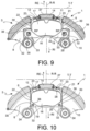
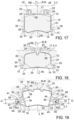
- FIG. 15 A similar solution, albeit simplified, is shown in figure 15 .
- a pair of pads 11, 12 is placed facing a disc 2 of a disc brake 3, suspended from a pin pad 51.
- a spring 52 presses the brake pads, in particular the plates of the pads away from the disc.
- the disc 2 during its operation tends to deform more in its annular portion further away from the rotation axis, i.e. from its constraint to the wheel hub of the vehicle, determining a deformation or axial vibration of said outer annular portion, in figure 15 shown by the dotted line, which moves the disc 2 towards the pads 11, 12, sometimes resulting in an undesirable contact which generates an undesirable residual braking torque which leads to a slight deceleration of the vehicle, vibration and sometimes annoying noises if not whistling.
- the pads are still guided axially, i.e. parallel to the rotation axis of the associable brake disc, by pins or guides which slide in suitable holes made in the support plates of said pads.
- the thrust exerted by the springs of the prior art is not aligned with said axial guides of the pads. This determines a friction action between the pins and the relative holes which, together with the axial thrust exerted by the plates, generates a torque on said pad.
- This torque tends to make the pad rotate distancing its radially innermost portion with negative effects both in terms of retraction and in terms of wear of said pads.
- anomalous consumption also affects the efficiency of braking and can generate the occurrence of vibrations and noise during said braking.
- the contrasting need is strongly felt to distance the pad as little as possible from the friction surfaces of the disc to have a braking device ready or reactive to the braking request by the driver.
- the objective of the present invention is therefore to devise and make available a brake pad for a disc brake of new conception which, despite being suspended does not rotate, moving further away from the disc in the axial direction at its radially innermost portion.
- a further objective of the present invention is to devise and make available a brake pad for a disc brake of new conception which is pulled in the radial direction by the action of an elastic device associated thereto, at least for most of its radial extension.
- a spring for example but not necessarily a shaped leaf spring
- the present invention also relates to a caliper assembly of a disc brake according to the appended claim 9 , and a method of distancing the brake pads from the brake disc according to claim 8 .
- This proposed solution creates a new type of pad which, while being suspended, is pulled radially outwards.
- this new type of pad is elastically suspended from a spring device, avoiding resting on the caliper body on the same side of the plate edge where the elastic action of the spring device is applied.
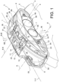
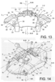
- reference numeral 1 globally denotes a disc brake caliper, comprising a caliper body 8 having a pair of half-bodies or half-calipers 9, 10 adapted to define a housing compartment 11 for a portion of an associable brake disc 2.
- the half-calipers 9, 10 are positioned on opposite sides to the housing compartment 11 in an axial direction X-X parallel to the rotation axis of the associable brake disc. Said axial direction X-X is also parallel to the direction of movement of the thrust pistons of the pads of the caliper 1, as well as the rotation axis A-A of the disc 2.
- the half-calipers 9, 10 may be separate from each other and joined for example by mechanical coupling means, or the half-calipers 9, 10 may be made in one piece, i.e. by making a caliper body 8 of the monobloc type.
- each half-caliper 9, 10 is made of aluminium or of an aluminium alloy.
- Said caliper 1 has elongated elements 53, 54 substantially facing the disc, for example an elongated element on the vehicle side 53 and an elongated element on the wheel side 54, joined together by end bridges 55, 56.
- the caliper body 8 may be fixed or floating, i.e. fitted with thrust means in both the half-calipers 9, 10, or have thrust means only on one side of the disc and associated with a portion of the caliper body, or floating, sliding on guides or pins on a second portion of the caliper body or bracket.
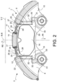
- the housing compartment 11 delimited by the caliper body 8 is configured to house at least one pair of pads 12, 13 positioned on opposite sides to said housing compartment 11, in the axial direction X-X.
- the housing compartment 11, is the shape of a sector of a disc and is radially delimited, according to another embodiment, by a central connecting bridge 14 of the half-calipers 9, 10 .
- the axial direction X-X is taken to mean a direction parallel to the rotation axis A-A of the disc 2, while the radial direction R-R is taken to mean a direction perpendicular to the axial direction X-X and directed towards the rotation axis of the associable brake disc.
- the circumferential or tangential direction T-T is taken to mean a direction in any point orthogonal to said axial direction X-X and said radial direction R-R.
- the pads 12,13 comprise a support plate 15 and a friction portion 16 suitable for exerting a friction force on the associable brake disc, in particular on opposite friction surfaces 4, 5 of the brake disc 3.
- the support plate 15 and the friction portion 16 may be made in separate parts, preferably in different materials, subsequently assembled together, or the pads 12, 13 may also be made in one piece.
- each half-caliper 9, 10 is provided with at least one housing seat for a piston suitable to press a brake pad 12; 13 against the associable brake disc 2, in the axial direction X-X.
- Each half-caliper 9, 10 may comprise a plurality of housing seats and relative pistons housed therein.
- the housing seat of a piston is of the type passing through the half-caliper 9, 10 i.e. extending between an inner wall of the half-caliper 6 facing the housing compartment 11 and an outer wall 7 of the half-caliper 9, 10, axially opposite said housing compartment 11.
- said housing seat is typically a cylindrical seat having an axis of symmetry parallel to said axial direction X-X.
- the half-caliper 9, 10 comprises a hollow cup-shaped insert 57 provided with a closed bottom 58 positioned on the outer wall 59 of the half-caliper.
- Said insert is made of metal, for example steel, or other materials, such as carbon, ceramic and/or plastic reinforced with carbon and the like.
- the pads 12, 13 comprise a support plate 15 and a friction portion 16 suitable for exerting a friction force on the associable brake disc.
- the support plate 15 and the friction portion 16 may be made in separate parts, preferably in different materials, subsequently assembled together, or the pads 12, 13 may also be made in one piece.
- the present invention applies to any type of pad and/or caliper body: it therefore also applies to calipers 1 having two or more pads for each half-caliper 9,10.
- the thrust means are for example a cylinder-piston group.
- the piston 61 is preferably hydraulically driven, but the drive can also be pneumatic or electromechanical.
- the piston 61 preferably has a cylindrical geometry.
- the piston 61 interfaces with the support plate 15 of the pad 12,13 so as to press the friction portion 16 against the associable brake disc.
- the support plate 15 comprises at least one guide hole 36 which receives in sliding coupling at least one axial guide 34 or 35 for the pad 12, 13.
- the guide hole 36 is positioned at a radial end of the caliper body 8, on the opposite side to the connecting bridges 55 and 56 and/or 14, with respect to the piston 61.
- the guide hole 36 receives the axial guide 34 or 35 with clearance so as to allow the axial sliding of the pads relative to said guide.
- the guide hole 36 is preferably counter-shaped to the axial guide 34 or 35.
- a brake pad 12, 13 of the brake disc 2 comprises a support plate 15 to rest on the friction surfaces 4, 5 of a brake disc 2 having a thrust surface 18 to receive the thrust of at least one piston 61, or equivalent thrust means 60, and a friction surface 19 to which a friction portion 16 is associated, associated with said support plate 15 to rest on a friction surface 4, 5 of said brake disc 2.
- Said disc brake defines an axial direction X-X parallel to the direction of rotation of the brake disc 2, a radial direction R-R orthogonal to said axial direction X-X and incident with it and a tangential or circumferential direction, T-T orthogonal to said axial direction X-X and said radial direction R-R.
- Said radial direction R-R defines an inward surface RI, when directed towards the axial direction coinciding with the rotation axis of the disc A-A, and an outward surface RE, when directed towards the opposite direction away from the axial direction coinciding with the rotation axis of the brake disc A-A.
- said pad comprises a support plate edge which delimits said thrust surface 18 and friction surface 19.
- said thrust plate edge 17 comprises an upper edge portion 28, substantially facing or directed outwards in said radial direction R-R.
- Said thrust plate edge 17 comprises a lower edge portion 20, substantially facing or directed inwards in said radial direction R-R.
- Said thrust plate edge 17 comprises two lateral edge portions 21, 22 opposite each other and substantially facing or directed in the tangential direction T-T, said lateral edge portions 21, 22 each comprise a lower lateral edge sub-portion 30, next to the lower edge portion 20, which extends by an extension less than or equal to a third of the longitudinal extension of said lateral edge portion 21, 22.
- said upper edge portion 28 of said thrust plate edge 17 comprises at least one tab 23 forming a seat 24, open or closed.
- a portion of the support plate 15 which is delimited by said lower lateral edge sub-portion 30, and/or by said lower edge portion 20, comprises a lower portion resting on the caliper body 31 support plate 15 defining a caliper support surface 32 resting on the support plate 15 of the caliper body 8 to exert a reaction to the thrust component of the spring device 27.
- said caliper support surface substantially faces, or has a sense, in the outward sense RE of said radial direction R-R to rest the pad directly or indirectly on the caliper body 8, so that said pad is pulled radially outwards substantially in its entire radial extension in an outward sense RE.
- the pad is pulled outwardly, or the pad is pulled radially.
- said caliper support surface 32 is made inside said support plate 15 which delimits said lower lateral edge sub-portion 30, and/or said lower edge portion 20, in the manner of an open seat or alternatively a slotted hole, and substantially faces, or has a sense, in the outward sense RE of said radial direction R-R, to rest on a reaction device associated with the caliper body 8, for example a pad support pin 34 or a pad support screw 35.
- said spring surface 25 is an undercut surface with respect to the upper edge portion 28.
- said tab 23 forming said open or closed seat 24 defining said spring surface 25 is a bracket which protrudes in a cantilever from said support plate 15.
- said support plate 15 is an axial-symmetric shape with respect to a median line parallel to the radial direction R-R.
- said spring surface 25 comprises at least one inclined portion with respect to the tangential direction T-T which extends, moving away from said tangential direction T-T, for example a line passing through the plate edge, going towards the outward radial sense RE, opening an angle A towards the radial direction R-R between 30 DEG and 50 DEG, preferably 45 DEG.
- said lower edge portion 20 is devoid of any spring surface 25 to receive the influence of a spring device 27.
- said lower lateral edge sub-portion 30 is devoid of any spring surface 25 to receive the influence of a spring device 27.
- said tab 23 forming said open or closed seat 24 defining said spring surface25 is placed in proximity of the edge between said upper edge portion 28 and said lateral edge portion 21 and/or 22.
- said spring surface 25 is facing said upper edge portion 28 positioned alongside the portion of friction material 16.
- said seat 24 defining said spring surface 25 is a closed seat, for example in the shape of a slot.
- said lower support portion of the caliper body 31 support plate 15 defining the caliper support surface 32 resting on the support plate of the caliper body 8, to exert a reaction to the thrust component having a radially outward sense RE of the stressing action of the spring device 27, is made in a support tab 33.
- said support tab 33 protrudes in a tangential direction T-T away from said friction portion 16.
- said support tab 33 protrudes in a tangential direction T-T away from said friction portion 16 substantially at or below the radially innermost portion of the friction portion 16.
- said support tab 33 forms a cantilever bracket defining externally to itself the caliper support surface 32 resting on the support plate of the caliper body 8.
- said support surface 32 is made as a slot 36 for supporting a portion of a pin 34 or screw 35, constrained to the caliper body.
- said eyelet profiles 38 have a substantially rectangular or square shape with a rounded top outer corner 41, a bottom outer corner 42, a bottom inner corner 43 and a top inner corner 44.
- a rounded top outer corner 41, 42, 43, 44 form said eyelet contact portions 40.
- said eyelet profiles 38 of each eyelet 36 have only one of said eyelet contact portions 40 positioned at said rounded bottom outer corner 42.
- the ratio between the height H of each eyelet 36 and the radius of eyelet curvature Ro of said single contact portion of eyelet 40 is in the range 2 to 2.1.
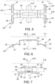
- a spring device 27 for a brake pad pulled outwards 12; 13 of the type described above comprises a spring body 45 of the spring device.
- said spring device body 45 comprises a coupling portion 46 to detachably couple the spring device 27 to the caliper body 8, for example, but not necessarily to the central bridge 14.
- said pad thrust portion 47 comprises at least one thrust surface 48, which in the operating position, is directed substantially in the outward radial direction RE.
- said thrust surface 48 is sloping passing towards the outside of the device in the axial direction X-X, proving inclined going towards the outside of the spring device 27 in the axial direction X-X, lowering itself in the inner radial direction RI gradually as it moves away.
- said spring device 27 extends longitudinally in the tangential direction T-T and has an axially symmetrical shape with respect to a centreline S-S, parallel to the tangential direction T-T, wherein said thrust surface 48 is made in an end portion 49 of the spring device 27 which moves away from said centreline S-S.
- said thrust surface 48 lowers moving away from said centreline S-S sloping in the axial direction X-X towards the inward radial direction RI.
- said thrust surface 48 is inclined in the axial direction X-X going towards the inward radial direction RI opening an angle B from 5 to 15 DEG, preferably 10 DEG.
- said thrust surface 48 is at least two sloping surfaces to influence the same pad 11, 12 in two separate positions.
- said at least two sloping surfaces 48 are placed at the axial and tangential ends of the spring device 27.
- said spring device 27 is a leaf spring, for example a shaped leaf spring.
- said leaf spring 27 is a spring in a single piece.
- said coupling portion 46 is adapted to couple to a central connecting bridge 14 of the caliper body 8 to connect in a substantially axial direction the two caliper half-bodies 9, 10.
- said coupling portion 46 externally radially embraces a portion of said central connecting bridge 14.
- said coupling portion 46 snap couples to undercut portions of said central connecting bridge 14.
- said spring device comprises elastic arms 50 which connect said pad thrust portions 47 to said coupling portion 46.
- a method of moving a brake pad 12, 13 of a disc brake assembly 3 away from a brake disc 2 will be described below.
- said pad 12, 13 comprises a plate 15 provided with a plate edge 17 and a friction portion 16.
- Said method comprises at least the steps of:
- said at least one pad is stressed by at least one spring device 27 only in the vicinity of an upper edge portion 28 of the support plate edge 17.
- said at least one pad 12; 13 is pulled radially between at least one application position of an elastic stress in the vicinity of its upper edge 28 and a support portion on the caliper body 8 in proximity of a lower edge portion 20 and/or a lower lateral edge sub-portion 30 of a portion of lateral edge 21; 22 of the support plate edge 17.
- a brake disc assembly 3 is described below which comprises a brake disc caliper 1 which houses at least one pad 12, 13 as described above.
- said assembly 1 comprises in addition to the pad as described above, a spring device as described above.
- the pad, the spring and the assembly described above it is possible to satisfy the need expressed to reduce the residual torque determined by the undesired contact of the pad with the brake disc, especially of the residual torque determined by accidental and unwanted contact of the radially outward annular portion of the disc which, being distant from its constraint (the hat attached to the stub axle of the vehicle), deforms more in the axial direction X-X, widening in the axial direction. Thanks to the proposed solutions the disc is prevented from interfering with the friction portion of the brake pad.
- the spring device described above it is possible to provide a spring, a shaped leaf spring, which makes it possible to influence the pads associated to the caliper body of a disc brake and which makes it possible to press the pads away from the disc of the disc brake, avoiding creating annoying vibrations and high frequency noises or whistling and preventing the pads from vibrating against the braking surfaces of the disc, remaining in proximity of the disc even when the braking action is not required creating an unwanted residual braking torque.
- the new and inventive concept of resting the pad described herein is characterised in that the spring pulls the brake pads towards the outside of the disc and that contrast elements, such as supports, prevent the translation of the pad in such direction (planes, pins or sliding screws). Contrary to the prior solutions the arm which radially separates the point of application of the spring on the brake pad from the point where the pad rests on the caliper body i.e. the radial arm on which the spring works is very broad, permitting the use of less rigid springs for the same load, with, among others, the following benefits:
- Another advantage of this solution is the reduction of residual torque due to the fact that the pads move away by effect of the spring starting from the radially outermost part, right where the disc deforms most, contrary to what happens with the suspended pads of the solutions of the prior art ( fig.15 ).
Landscapes
- Engineering & Computer Science (AREA)
- General Engineering & Computer Science (AREA)
- Mechanical Engineering (AREA)
- Braking Arrangements (AREA)
Claims (9)
- Belag (12, 13) einer Scheibenbremse (2) zum Anliegen an den Reibflächen (4, 5) einer Bremsscheibe (2), wobei die Bremsscheibe eine axiale Richtung (X-X) parallel zu der Rotationsrichtung der Bremsscheibe (2), eine radiale Richtung (R-R) orthogonal zu der axialen Richtung (X-X) und sie schneidend und eine tangentiale oder umfängliche Richtung (T-T) orthogonal zu der axialen Richtung (X-X) und der radialen Richtung (R-R) definiert, wobei die radiale Richtung (R-R) einen nach innen gerichteten Sinn (RI) definiert, wenn sie in Richtung mit der Rotationsachse der Scheibe (A-A) zusammenfallenden axialen Richtung gerichtet ist, sowie einen nach außen gerichteten Sinn (RE), wenn sie in Richtung der entgegengesetzten Richtung weg von der mit der Rotationsachse der Bremsscheibe (A-A) zusammenfallenden axialen Richtung gerichtet ist, wobei der Bremsbelag (12, 13) eine Trageplatte (15) mit einer Schubfläche (18) zum Aufnehmen des Schubs von wenigstens einem Kolben umfasst, sowie eine Reibfläche (19), welcher ein Reibabschnitt (16) zugeordnet ist, welcher der Trageplatte (15) zugeordnet ist, um an einer Reibfläche (4, 5) der Bremsscheibe (2) anzuliegen, wobei der Belag einen Trageplatten-Rand (17) umfasst, welcher die Schubfläche (18) und Reibfläche (19) begrenzt, wobei der Schubflächen-Rand (17) einen oberen Randabschnitt (28) umfasst, welcher im Wesentlichen in Richtung nach Außen im Sinne nach außen (RE) der radialen Richtung (R-R) weist oder gerichtet ist, wobei der Schubplatten-Rand (17) einen oberen Randabschnitt (20) umfasst, welcher im Wesentlichen im Sinne nach innen (RI) der radialen Richtung (R-R) weist oder gerichtet ist, wobei der Schubplatten-Rand (17) zwei laterale Randabschnitte (21, 22) einander gegenüber und im Wesentlichen in die tangentiale Richtung (T-T) weisend oder gerichtet umfasst, wobei die lateralen Randabschnitte (21, 22) jeweils einen unteren lateralen Rand-Unterabschnitt (30) neben dem unteren Randabschnitt (20) umfassen, welcher sich um eine Erstreckung erstreckt, welche kleiner oder gleich einem Drittel der longitudinalen Erstreckung des lateralen Randabschnitts (21, 22) ist, wobei:- der obere Randabschnitt (28) des Schubplatten-Rands (17) wenigstens einen Streifen (23) umfasst, welcher einen Sitz (24) offen oder geschlossen bildet und eine Federfläche (25) definiert, welche im Wesentlichen in dem Sinne nach innen (RI) der radialen Richtung (R-R) weist oder gerichtet ist, um einen Schubabschnitt (26) einer Federvorrichtung (27) aufzunehmen und zu tragen, welche dazu eingerichtet ist, den Bremsbelag mit wenigstens einer Schubkomponente zu drücken, welche in dem Sinne nach Außen (RE) der radialen Richtung (R-R) gerichtet ist,
wobei entlang des gesamten oberen Randabschnitts (28) kein oberer Trageabschnitt des Sattelkörpers (8) vorliegt, wobei das Tragen der Platte oder des Belags durch den Sattelkörper (8) erhaben verhindert wird, um eine Reaktion auf die Schubkomponente mit einem Sinne nach außen (RE) der radialen Richtung (R-R) auf die Lastwirkung der Federvorrichtung (27) auszuüben; und wobei- ein Abschnitt der Trageplatte (15), welcher von dem unteren lateralen Rand-Unterabschnitt (30) und/oder von dem unteren Randabschnitt (20) begrenzt ist, einen unteren Sattelkörper-Trageabschnitt (31) der Platte (15) umfasst, wobei eine Sattel-Tragefläche (32) definiert ist, welche die Platte (15) an dem Sattelkörper (8) trägt, um eine Reaktion auf die Schubkomponente der Federvorrichtung (27) auszuüben; und wobei- die Sattel-Tragefläche (32) im Wesentlichen in dem Sinne nach außen (RE) der radialen Richtung (R-R) weist oder einen Sinn aufweist, um direkt oder indirekt an dem Sattelkörper (8) anzuliegen,so dass der Belag im Wesentlichen in seiner gesamten radialen Erstreckung radial nach außen gezogen wird, in dem Sinne nach außen (RE);dadurch gekennzeichnet, dass der obere Rand (28) zwei Streifen (23) pro Feder umfasst; und wobeientlang der gesamten longitudinalen Erstreckung des oberen Rands (28) keine anderen Streifen vorliegen mit Ausnahme von Vertiefungen oder Aufnahmen für Abnutzungssensoren des Reibabschnitts (16) des Belags (14; 15);wobei die Trageplatte (15) eine achsensymmetrische Form bezüglich einer Mittellinie parallel zu der radialen Richtung (R-R) ist. - Belag (12, 13) einer Scheibenbremse (2) nach Anspruch 1, wobei die Sattel-Tragefläche (32) entlang dem unteren lateralen Rand-Unterabschnitt (30) und/oder dem unteren Randabschnitt (20) gebildet ist und im Wesentlichen in dem Sinne nach außen (RE) der radialen Richtung (R-R) weist oder einen Sinn aufweist, um an dem Sattelkörper (8) anzuliegen;- wobei die Sattel-Tragefläche (32) innerhalb der Trageplatte (15) gebildet ist, welche den unteren lateralen Rand-Unterabschnitt (30) und/oder den unteren Randabschnitt (20) in der Weise eines offenen Sitzes oder alternativ einer Öse begrenzt, und im Wesentlichen in dem Sinne nach außen (RE) der radialen Richtung (R-R) weist oder einen Sinn aufweist, um an einer Reaktionsvorrichtung anzuliegen, welche dem Sattelkörper (8) zugeordnet ist;- wobei die Federfläche (25) eine hinterschnittene Fläche bezüglich des oberen Randabschnitts (28) ist und/oder wobei- der Streifen (23), welcher den offenen oder geschlossenen Sitz (24) bildet, welcher die Federfläche (25) definiert, eine Klammer ist, welche in einer Auskragung von der Trageplatte (15) vorsteht, und/oder wobei- über den oberen Randabschnitt (28) lediglich Streifen (23), welche den offenen oder geschlossenen Sitz (24) bilden, welcher die Federfläche (25) definiert, vorliegen, wobei andere Streifen vermieden werden.
- Belag (12, 13) einer Scheibenbremse (2) nach einem der vorhergehenden Ansprüche, wobei:- die beiden Streifen (23) zueinander hin gefaltet sind, so dass die beiden Sitze (24) zueinander weisen; oder wobei- die beiden Streifen (23) in entgegengesetzte Richtungen gefaltet sind, so dass die beiden Sitze (24) einander entgegengesetzt sind.
- Belag (12, 13) einer Scheibenbremse (2) nach einem der vorhergehenden Ansprüche, wobei:- die Federfläche (25) wenigstens einen Teil umfasst, welcher in eine tangentiale Richtung (T-T) gerichtet ist; oder wobei- die Federfläche (25) wenigstens einen geneigten Abschnitt bezüglich der tangentialen Richtung (T-T) umfasst, welcher sich von der tangentialen Richtung (T-T) weg bewegt und in Richtung der radialen Richtung nach außen (RE) läuft, wobei ein Winkel (A) in Richtung der radialen Richtung (R-R) zwischen 30 Grad und 50 Grad, vorzugsweise 45 Grad, geöffnet ist; und/oder wobei- der untere Randabschnitt (20) frei von jeglicher Federfläche (25) ist; und/oder wobei- der untere laterale Rand-Unterabschnitt (30) frei von jeglicher Federfläche (25) ist; und/oder wobei- der Streifen (23), welcher den offenen oder geschlossenen Sitz (24) bildet, welcher die Federfläche (25) definiert, in der Nähe des Rands zwischen dem oberen Randabschnitt (28) und dem lateralen Randabschnitt (21 und/oder 22) platziert ist; und/oder wobei- die Federfläche (25) zu dem oberen Randabschnitt (28) weist, welcher längsseits des Abschnitts von Reibmaterial (16) positioniert ist; oder wobei- der Sitz (24), welcher die Federfläche (25) definiert, ein geschlossener Sitz ist, beispielsweise in der Form einer Aussparung.
- Belag (12, 13) einer Scheibenbremse (2) nach einem der vorhergehenden Ansprüche, wobei:- der untere Sattelkörper-Trageabschnitt (31) der Platte (15), welcher eine Sattel-Tragefläche (32) definiert, welche die Platte (15) an dem Sattelkörper (8) trägt, um eine Reaktion auf die Schubkomponente, welche eine Richtung nach radial außen (RE) aufweist, der Lastwirkung der Federvorrichtung (27) auszuüben, in einem Tragestreifen (33) gebildet ist; und wobei- der Tragestreifen (33) in einer Auskragung von dem unteren lateralen Rand-Unterabschnitt (30) oder dem unteren Randabschnitt (20) vorsteht; und/oder wobei- der Tragestreifen (33) in einer tangentialen Richtung (T-T) weg von dem Reibabschnitt (16) vorsteht; und/oder wobei- der Tragestreifen (33) eine Auskragungsklammer bildet, welche außerhalb von sich die Sattel-Tragefläche (32) definiert, welche die Trageplatte des Sattelkörpers (8) trägt; oder wobei- der Tragestreifen (33) eine Auskragungsklammer bildet, welche intern oder teilweise intern oder in einem Hinterschnitt die Sattel-Tragefläche (32) definiert, welche die Tragefläche des Sattelkörpers (8) trägt; oder wobei- die Tragefläche (32) als eine Aussparung (36) zum Tragen eines Abschnitts eines Stifts (34) oder einer Schraube (35) gebildet ist; oder wobei- der Belag (14 und/oder 15) mit einer oder mehreren Aussparungen oder Ösen (36) zum Aufnehmen entsprechender Stifte (34; 35) des Sattels (8) bereitgestellt ist, wobei die Stifte (34; 35) Stiftprofile (37) definieren und die Ösen (36) Ösenprofile (38) definieren, wobei die Stiftprofile (37) einen oder mehrere gekrümmte Stift-Kontaktabschnitte (39) mit Stift-Krümmungsradien (Rp) aufweisen und die Ösenprofile (38) einen oder mehrere gekrümmte Ösen-Kontaktabschnitte (40) mit Ösen-Krümmungsradien (Ro) aufweisen, so dass der Kontakt zwischen dem Belag (14 und/oder 15) und den Stiften (34; 35) wenigstens teilweise an den Stift- (39) und Ösen- (40) Kontaktabschnitten stattfinden kann, wobei die Ösen-Krümmungsradien (Ro) größer sind als die Stift-Krümmungsradien (Rp); oder wobei- die Ösenprofile (38) eine im Wesentlichen rechteckige oder quadratische Form mit einer abgerundeten oberen äußeren Ecke (41), einer unteren äußeren Ecke (42), einer unteren inneren Ecke (43) und einer oberen inneren Ecke (44) aufweisen, wobei eine oder mehrere der abgerundeten Ecken (41, 42, 43, 44) die Ösen-Kontaktabschnitte (40) bilden; und/oder wobei die Ösenprofile (38) von jeder Öse (36) lediglich einen der Ösen-Kontaktabschnitte (40) aufweisen, welcher an der abgerundeten unteren äußeren Ecke (42) positioniert ist; und wobei- das Verhältnis zwischen der Höhe (H) von jeder Öse (36) und dem Radius der Ösenkrümmung (Ro) des einzelnen Ösen-Kontaktabschnitts (40) im Bereich von 2 bis 2,1 liegt.
- Federvorrichtung (27) für einen Bremsbelag nach einem der Ansprüche 1 bis 5, welche nach außen (12; 13) gezogen ist, umfassend:- einen Federvorrichtungs-Körper (45);- wobei der Federvorrichtungs-Körper (45) einen Kopplungsabschnitt (46) umfasst, um die Federvorrichtung (27) lösbar an den Sattelkörper (8) zu koppeln;- wobei der Federvorrichtungs-Körper (45) einen Belag-Schubabschnitt (47) zum Beeinflussen des Belags (13, 14) umfasst, indem er ihn in Richtung der radialen Richtung nach außen (RE) zieht, und um ihn wenigstens weg von einer Bremsscheibe (2) zu beeinflussen;
wobei- der Belag-Schubabschnitt (47) wenigstens eine Schubfläche (48) umfasst, welche in der Betriebsposition im Wesentlichen in die radiale Richtung nach außen (RE) gerichtet ist, wobei- die Schubfläche (48) in Richtung der Außenseite der Vorrichtung verlaufend in der axialen Richtung (X-X) abfällt, wobei sie als in Richtung der Außenseite der Federvorrichtung (27) in der axialen Richtung (X-X) laufend geneigt gezeigt ist, in der radialen Richtung nach innen (RI) graduell absinkend, wenn sie sich entfernt;
dadurch gekennzeichnet, dass- die Federvorrichtung (27) eine Blattfeder-Vorrichtung ist; und wobei- die Blattfeder (27) eine Feder in einem einzelnen Stück ist. - Federvorrichtung (27) nach Anspruch 6, wobei in Betriebsbedingungen- die Federvorrichtung (27) sich longitudinal in die tangentiale Richtung (T-T) erstreckt und eine achsensymmetrische Form bezüglich einer Mittellinie (S-S) parallel zu der tangentialen Richtung (T-T) aufweist, wobei die Schubfläche (48) in einem Endabschnitt (49) der Vorrichtungsfeder (27) gebildet ist, welcher sich von der Mittellinie (S-S) weg bewegt, und wobei die Schubfläche (48) sich weg von der Mittellinie (S-S) bewegend absinkt, in der axialen Richtung (X-X) in Richtung der radialen Richtung nach innen (RI) abfallend; und/oder wobei- die Schubfläche (48) in der axialen Richtung (X-X) in Richtung der radialen Richtung nach innen (RI) laufend geneigt ist, wobei ein Winkel B von 5 bis 15 Grad, vorzugsweise 10 Grad, geöffnet ist;- die Schubfläche (48) wenigstens zwei abfallende Flächen ist, um denselben Belag (11, 12) in zwei separaten Positionen zu beeinflussen; und wobei- die wenigstens zwei abfallenden Flächen (48) an den axialen und tangentialen Enden der Federvorrichtung (27) platziert sind; und/oder wobei- der Kopplungsabschnitt (46) dazu eingerichtet ist, mit einer zentralen Verbindungsbrücke (14) des Sattelkörpers (8) zu koppeln, um die beiden Sattel-Halbkörper (9, 10) in einer im Wesentlichen axialen Richtung zu verbinden; und/oder wobei- die Federvorrichtung elastische Arme (50) umfasst, welche die Belag-Schubabschnitte (47) mit dem Kopplungsabschnitt (46) verbinden.
- Verfahren zum Bewegen eines Bremsbelags (12, 13) nach einem der Ansprüche 1 bis 5 einer Scheibenbremsen-Anordnung (3) weg von einer Bremsscheibe (2), wobei der Belag (12, 13) eine Platte (15) umfasst, welche mit einem Plattenrand (17) und einem Reibabschnitt (16) bereitgestellt ist, wobei das Verfahren die Schritte umfasst:- Belasten von wenigstens einem Belag mittels wenigstens einer Federvorrichtung (27) in die radiale Richtung nach außen (RE), Ausüben der Wirkung in der Nähe eines oberen Randabschnitts (28) des Trageplatten-Rands (17);- Verhindern eines Entgegenwirkens der Wirkung der Federvorrichtung (27), wobei der Belag (12, 13) an dem Sattelkörper (8) in der Nähe eines oberen Randabschnitts (28) anliegt;- Entgegenwirken der Wirkung der Federvorrichtung (27), wobei der Belag (12, 13) an dem Sattelkörper (8) lediglich in der Nähe eines unteren Randabschnitts (20) und/oder eines unteren lateralen Rand-Unterabschnitts (30) eines lateralen Randabschnitts (21; 22) des Trageplatten-Rands (17) anliegt.
- Bremsscheiben-Anordnung (3), umfassend einen Bremsscheiben-Sattel (1), welcher einen Bremsbelag (12, 13) nach einem der Ansprüche 1 bis 5 aufnimmt; und/oder wobei die Anordnung (1) ferner eine Federvorrichtung nach einem der Ansprüche 6 und 7 umfasst.
Applications Claiming Priority (2)
| Application Number | Priority Date | Filing Date | Title |
|---|---|---|---|
| ITMI20140657 | 2014-04-08 | ||
| PCT/IB2015/052549 WO2015155708A1 (en) | 2014-04-08 | 2015-04-08 | Disc brake pad, spring for disc brake caliper and disk brake caliper assembly |
Publications (3)
| Publication Number | Publication Date |
|---|---|
| EP3129672A1 EP3129672A1 (de) | 2017-02-15 |
| EP3129672B1 EP3129672B1 (de) | 2018-04-11 |
| EP3129672B2 true EP3129672B2 (de) | 2024-09-18 |
Family
ID=50981715
Family Applications (1)
| Application Number | Title | Priority Date | Filing Date |
|---|---|---|---|
| EP15721858.7A Active EP3129672B2 (de) | 2014-04-08 | 2015-04-08 | Scheibenbremsbelag, feder für scheibenbremszange und scheibenbremszangenanordnung |
Country Status (4)
| Country | Link |
|---|---|
| US (1) | US10316912B2 (de) |
| EP (1) | EP3129672B2 (de) |
| CN (1) | CN106460975B (de) |
| WO (1) | WO2015155708A1 (de) |
Families Citing this family (38)
| Publication number | Priority date | Publication date | Assignee | Title |
|---|---|---|---|---|
| EP3175134B1 (de) * | 2014-08-01 | 2018-03-21 | Freni Brembo S.p.A. | Bremsbelagfeder zur beeinflussung der bremsbeläge eines scheibenbremssattels |
| EP3023666B2 (de) | 2014-11-20 | 2022-09-14 | Meritor Heavy Vehicle Braking Systems (UK) Limited | Scheibenbremsanordnung |
| DE102015121942A1 (de) * | 2015-12-16 | 2017-06-22 | Knorr-Bremse Systeme für Nutzfahrzeuge GmbH | Scheibenbremse für ein Nutzfahrzeug sowie Bremsbelag für eine Scheibenbremse |
| DE102015122563A1 (de) * | 2015-12-22 | 2017-06-22 | Bpw Bergische Achsen Kg | Bremsbelag für eine Scheibenbremse, Scheibenbremse, Niederhalter für Bremsbeläge einer Scheibenbremse |
| ITUB20159344A1 (it) | 2015-12-23 | 2017-06-23 | Freni Brembo Spa | Molla a lamina per pinza freno e corpo pinza comprendente detta molla |
| US10012277B2 (en) * | 2016-08-10 | 2018-07-03 | E&G Corporation, LLc | Bracket for brake caliper cover |
| IT201600130800A1 (it) | 2016-12-23 | 2018-06-23 | Freni Brembo Spa | Dispositivo a molla per freno a disco, assieme di pastiglia e molla e pinza freno |
| US10113599B2 (en) * | 2017-02-07 | 2018-10-30 | Edwin Beachy | Retaining bracket for disc brake caliper and kit including the same |
| KR101908011B1 (ko) * | 2017-03-23 | 2018-10-16 | 주식회사 만도 | 차량용 디스크브레이크 |
| USD864062S1 (en) * | 2017-04-13 | 2019-10-22 | Freni Brembo S.P.A. | Disc brake caliper |
| JP1603869S (de) * | 2017-04-13 | 2018-05-14 | ||
| US10591003B2 (en) * | 2017-06-16 | 2020-03-17 | Polaris Industries Inc. | Brake assembly shield and scraper |
| US20190120308A1 (en) * | 2017-10-19 | 2019-04-25 | Hb Performance Systems, Inc. | Anti-rattle spring for brake caliper assembly |
| DE102018002886A1 (de) * | 2018-04-10 | 2019-10-10 | Lucas Automotive Gmbh | Bremsbelaganordnung für eine Scheibenbremse einer Fahrzeugbremsanlage |
| IT201800006504A1 (it) * | 2018-06-20 | 2019-12-20 | Molla per pastiglie d’attrito in una pinza per freno a disco | |
| IT201800006505A1 (it) * | 2018-06-20 | 2019-12-20 | Molla per pastiglie d’attrito in una pinza per freno a disco | |
| IT201800006498A1 (it) * | 2018-06-20 | 2019-12-20 | Molla per pastiglie d'attrito in una pinza per freno a disco | |
| DE102018007286A1 (de) * | 2018-09-14 | 2020-03-19 | Lucas Automotive Gmbh | Scheibenbremse für eine Fahrzeugbremsanlage |
| IT201800020581A1 (it) | 2018-12-20 | 2020-06-20 | Freni Brembo Spa | Assieme di pastiglia e molla per freno a disco e pinza freno |
| IT201800020572A1 (it) * | 2018-12-20 | 2020-06-20 | Freni Brembo Spa | Assieme di pastiglia e molla per una pinza freno |
| IT201800020401A1 (it) * | 2018-12-20 | 2020-06-20 | Freni Brembo Spa | Molla ritorno pastiglie per un corpo pinza di freno a disco |
| USD931171S1 (en) * | 2019-03-27 | 2021-09-21 | Freni Brembo S.P.A. | Brake caliper |
| CN113710918B (zh) * | 2019-04-12 | 2024-12-17 | 沃尔沃卡车集团 | 用于车辆的制动衬块、制动装置、制动系统和车辆 |
| IT201900006965A1 (it) * | 2019-05-17 | 2020-11-17 | Freni Brembo Spa | Corpo pinza per una pinza freno |
| USD922280S1 (en) * | 2019-08-02 | 2021-06-15 | Mando Corporation | Dust reduction device for an automobile |
| KR102749391B1 (ko) * | 2019-12-06 | 2025-01-02 | 현대모비스 주식회사 | 캘리퍼 브레이크용 패드 스프링 |
| CN110905945B (zh) * | 2019-12-11 | 2021-10-26 | 隆中控股集团股份有限公司 | 一种轮毂盘总成或制动盘的拆换方法 |
| WO2021164877A1 (en) | 2020-02-20 | 2021-08-26 | Volvo Truck Corporation | Brake pad retainer system, brake pad and vehicle |
| JP7456885B2 (ja) | 2020-08-07 | 2024-03-27 | 曙ブレーキ工業株式会社 | ディスクブレーキ装置 |
| JP7476027B2 (ja) | 2020-08-07 | 2024-04-30 | 曙ブレーキ工業株式会社 | ディスクブレーキ用パッド |
| CN115596784A (zh) * | 2021-06-28 | 2023-01-13 | 比亚迪股份有限公司(Cn) | 用于制动器的弹性件以及制动器 |
| JP7618512B2 (ja) | 2021-07-07 | 2025-01-21 | 曙ブレーキ工業株式会社 | ディスクブレーキ装置用パッドクリップ及びディスクブレーキ装置 |
| CN117677781B (zh) * | 2021-07-28 | 2024-07-16 | 日本轻金属株式会社 | 活塞收容体 |
| KR20230101430A (ko) * | 2021-12-29 | 2023-07-06 | 현대모비스 주식회사 | 브레이크 장치용 패드 라이너 |
| CN217440641U (zh) * | 2022-04-29 | 2022-09-16 | 蔚来汽车科技(安徽)有限公司 | 制动钳组件、制动器及车辆 |
| IT202300004659A1 (it) * | 2023-03-13 | 2024-09-13 | Brembo Spa | Molla di riposizionamento, assieme di pinza freno e molla di riposizionamento |
| CN116906479B (zh) * | 2023-08-21 | 2026-02-24 | 采埃孚汽车系统(武汉)有限公司 | 摩擦片磨损检测装置和制动卡钳总成 |
| IT202300022947A1 (it) * | 2023-10-31 | 2025-05-01 | Brembo Spa | Molla a nastro sagomata per disporsi a cavaliere di un disco freno |
Citations (16)
| Publication number | Priority date | Publication date | Assignee | Title |
|---|---|---|---|---|
| US3899052A (en) † | 1974-05-20 | 1975-08-12 | Bendix Corp | Disc brake |
| FR2323920A2 (fr) † | 1975-09-12 | 1977-04-08 | Ferodo Sa | Perfectionnements apportes aux organes de freins |
| DE2845959A1 (de) † | 1978-10-21 | 1980-04-30 | Teves Gmbh Alfred | Scheibenbremse |
| JPS57167538A (en) † | 1981-04-03 | 1982-10-15 | Nissan Motor Co Ltd | Disc brake |
| US4773511A (en) † | 1986-06-04 | 1988-09-27 | Lucas Industries Public Limited Company | Hold-down leaf spring for the brake lining backplate of a disc brake or for the pressure distributor plate which abuts the brake lining backplate |
| WO1993012358A1 (en) † | 1991-12-10 | 1993-06-24 | Ferodo Limited | Brake pad |
| JPH10299799A (ja) † | 1997-04-24 | 1998-11-10 | Hitachi Chem Co Ltd | ディスクパッド |
| US20030042085A1 (en) † | 2001-09-06 | 2003-03-06 | Dong-Hoon Kang | Automobile brake caliper for reducing noise |
| JP2008032125A (ja) † | 2006-07-28 | 2008-02-14 | Hitachi Ltd | ディスクブレーキ |
| US20090283372A1 (en) † | 2006-12-20 | 2009-11-19 | Toyota Jidosha Kabushiki Kaisha | Disc brake device |
| DE102008051236A1 (de) † | 2008-10-10 | 2010-04-15 | Lucas Automotive Gmbh | Scheibenbremse für eine Kraftfahrzeugbremsanlage und Belaghaltefederanordnung hierfür |
| JP2010101463A (ja) † | 2008-10-27 | 2010-05-06 | Akebono Brake Ind Co Ltd | ディスクブレーキ |
| JP2011163444A (ja) † | 2010-02-09 | 2011-08-25 | Nissin Kogyo Co Ltd | 車両用ディスクブレーキ |
| WO2011151235A1 (de) † | 2010-06-02 | 2011-12-08 | Continental Teves Ag & Co. Ohg | Festsattelbremse und bremsbelag für eine festsattelbremse |
| US20120298457A1 (en) † | 2010-05-20 | 2012-11-29 | Advics Co., Ltd. | Disc brake apparatus |
| EP2871381A1 (de) † | 2013-11-07 | 2015-05-13 | Akebono Brake Industry Co., Ltd. | Auflagefeder für Scheibenbremse |
Family Cites Families (39)
| Publication number | Priority date | Publication date | Assignee | Title |
|---|---|---|---|---|
| US4046232A (en) | 1974-03-28 | 1977-09-06 | General Motors Corporation | Disc brake sliding caliper assembly with brake pads of a common pattern, and method of construction |
| AU6759981A (en) * | 1980-03-01 | 1981-09-10 | Lucas Industries Limited | Disc brakes and friction pad assemblies therefor |
| US4460067A (en) | 1981-02-20 | 1984-07-17 | Toyota Jidosha Kogyo Kabushiki Kaisha | Pad-wear-limit warning device for disc brake |
| JPS5857528A (ja) | 1981-09-29 | 1983-04-05 | Nissan Motor Co Ltd | デイスクブレ−キ |
| DE3139942A1 (de) * | 1981-10-08 | 1983-04-28 | Alfred Teves Gmbh, 6000 Frankfurt | Bremsbackenanordnung |
| JPS5899527A (ja) | 1981-12-07 | 1983-06-13 | Akebono Brake Ind Co Ltd | インテグラルナックルタイプのサポート部を有するデイスクブレーキの仮組体構造 |
| FR2582763B1 (fr) * | 1985-05-30 | 1987-07-24 | Bendix France | Ressort de plaque de poussee pour frein a disque |
| GB2178807B (en) * | 1985-08-02 | 1989-01-18 | Automotive Products Plc | A disc brake caliper assembly |
| US4844206A (en) | 1987-12-18 | 1989-07-04 | Allied-Signal Inc. | Dual disk brake |
| DE3804846C2 (de) * | 1988-02-17 | 1995-04-27 | Westfalia Becorit Ind Tech | Hydraulisch entsperrbares Rückschlagventil, insbesondere für hydraulische Ausbausysteme |
| DE3910154C2 (de) * | 1989-03-29 | 1998-07-02 | Perrot Bremse Gmbh Deutsche | Blattfederanordnung zum Niederhalten der Bremsbelagträger in einer Scheibenbremse |
| DE4020287A1 (de) | 1990-06-26 | 1992-01-02 | Knorr Bremse Ag | Belaghalterung in scheibenbremsen fuer strassenfahrzeuge, insbesondere nutzfahrzeuge |
| DE9013699U1 (de) | 1990-10-01 | 1992-02-13 | Lucas Industries P.L.C., Birmingham, West Midlands | Scheibenbremse und Bremsbackenpaar für eine solche |
| WO1992017713A1 (de) | 1991-04-04 | 1992-10-15 | Alfred Teves Gmbh | Festsattel-teilbelagscheibenbremse |
| FR2704036B1 (fr) * | 1993-04-15 | 1995-06-09 | Alliedsignal Europ Services | Frein a disque utilisant un patin tire a appui permanent. |
| JPH07158669A (ja) | 1993-12-07 | 1995-06-20 | Nissin Kogyo Kk | 車両用ディスクブレーキ |
| JPH07229526A (ja) | 1994-02-21 | 1995-08-29 | Suzuki Motor Corp | ピンスライド式ブレーキキャリパー |
| DE4426603A1 (de) | 1994-07-27 | 1996-02-01 | Perrot Bremsen Gmbh | Vorrichtung zum Halten eines Bremsbelages in einer Scheibenbremse |
| JP3871746B2 (ja) * | 1996-10-23 | 2007-01-24 | 曙ブレーキ工業株式会社 | ディスクブレーキ用パッドクリップ |
| US6247560B1 (en) | 1996-12-12 | 2001-06-19 | Federal-Mogul Technology Limited | Slidable brake disc system |
| US5875873A (en) | 1997-05-05 | 1999-03-02 | Meritor Heavy Vehicle Systems, Llc | Air disc brake anti-rattle design |
| FR2800140B1 (fr) | 1999-10-26 | 2002-01-11 | Bosch Gmbh Robert | Ressort de guidage d'elements de friction et frein a disque comportant au moins un tel ressort |
| JP4552173B2 (ja) | 2001-03-21 | 2010-09-29 | 日立オートモティブシステムズ株式会社 | ディスクブレーキ |
| ATE290177T1 (de) * | 2001-10-31 | 2005-03-15 | Freni Brembo Spa | Blattfederelement zum verspannen von scheibenbremsbelägen |
| DE10222110B4 (de) * | 2002-05-17 | 2006-02-09 | Federal-Mogul Friction Products Gmbh | Bremsbelag mit Schutzlippe für Scheibenbremse |
| JP2004176868A (ja) | 2002-11-28 | 2004-06-24 | Advics:Kk | ディスクブレーキ |
| GB0301799D0 (en) | 2003-01-25 | 2003-02-26 | Meritor Heavy Vehicle Braking | Disc brake pad hold down spring and backplate |
| GB0302186D0 (en) * | 2003-01-30 | 2003-03-05 | Meritor Heavy Vehicle Braking | A disc brake pad spring |
| EP1709341B1 (de) | 2003-12-30 | 2010-10-13 | Freni Brembo S.p.A. | Bremsbelag, federelement und bremssattel für eine scheibenbremse |
| JP4492271B2 (ja) | 2004-09-22 | 2010-06-30 | 株式会社アドヴィックス | パッド吊下げ型のディスクブレーキ |
| JP4745803B2 (ja) | 2005-11-28 | 2011-08-10 | 日立オートモティブシステムズ株式会社 | ディスクブレーキ |
| ITTO20060253A1 (it) * | 2006-04-05 | 2007-10-06 | Raicam S P A | Freno a tamburo |
| DE102007046945B4 (de) * | 2007-10-01 | 2009-07-16 | Knorr-Bremse Systeme für Nutzfahrzeuge GmbH | Bremsbelaghalterung und Bremsbelag einer Scheibenbremse |
| DE102007049981B4 (de) * | 2007-10-18 | 2009-07-30 | Knorr-Bremse Systeme für Nutzfahrzeuge GmbH | Bremsbelag einer Scheibenbremse |
| IT1396961B1 (it) * | 2009-12-24 | 2012-12-20 | Freni Brembo Spa | Corpo pinza di un freno a disco |
| ITMI20111693A1 (it) * | 2011-09-20 | 2013-03-21 | Freni Brembo Spa | Corpo pinza per freno a disco |
| CN106536961B (zh) * | 2014-05-27 | 2019-01-29 | 福乐尼·乐姆宝公开有限公司 | 盘式制动器的卡钳的弹簧 |
| EP3023666B2 (de) * | 2014-11-20 | 2022-09-14 | Meritor Heavy Vehicle Braking Systems (UK) Limited | Scheibenbremsanordnung |
| US9726243B2 (en) * | 2015-03-20 | 2017-08-08 | Bendix Spicer Foundation Brake Llc | Disc brake pad retention system and mounting method |
-
2015
- 2015-04-08 US US15/302,923 patent/US10316912B2/en active Active
- 2015-04-08 WO PCT/IB2015/052549 patent/WO2015155708A1/en not_active Ceased
- 2015-04-08 EP EP15721858.7A patent/EP3129672B2/de active Active
- 2015-04-08 CN CN201580030481.3A patent/CN106460975B/zh active Active
Patent Citations (16)
| Publication number | Priority date | Publication date | Assignee | Title |
|---|---|---|---|---|
| US3899052A (en) † | 1974-05-20 | 1975-08-12 | Bendix Corp | Disc brake |
| FR2323920A2 (fr) † | 1975-09-12 | 1977-04-08 | Ferodo Sa | Perfectionnements apportes aux organes de freins |
| DE2845959A1 (de) † | 1978-10-21 | 1980-04-30 | Teves Gmbh Alfred | Scheibenbremse |
| JPS57167538A (en) † | 1981-04-03 | 1982-10-15 | Nissan Motor Co Ltd | Disc brake |
| US4773511A (en) † | 1986-06-04 | 1988-09-27 | Lucas Industries Public Limited Company | Hold-down leaf spring for the brake lining backplate of a disc brake or for the pressure distributor plate which abuts the brake lining backplate |
| WO1993012358A1 (en) † | 1991-12-10 | 1993-06-24 | Ferodo Limited | Brake pad |
| JPH10299799A (ja) † | 1997-04-24 | 1998-11-10 | Hitachi Chem Co Ltd | ディスクパッド |
| US20030042085A1 (en) † | 2001-09-06 | 2003-03-06 | Dong-Hoon Kang | Automobile brake caliper for reducing noise |
| JP2008032125A (ja) † | 2006-07-28 | 2008-02-14 | Hitachi Ltd | ディスクブレーキ |
| US20090283372A1 (en) † | 2006-12-20 | 2009-11-19 | Toyota Jidosha Kabushiki Kaisha | Disc brake device |
| DE102008051236A1 (de) † | 2008-10-10 | 2010-04-15 | Lucas Automotive Gmbh | Scheibenbremse für eine Kraftfahrzeugbremsanlage und Belaghaltefederanordnung hierfür |
| JP2010101463A (ja) † | 2008-10-27 | 2010-05-06 | Akebono Brake Ind Co Ltd | ディスクブレーキ |
| JP2011163444A (ja) † | 2010-02-09 | 2011-08-25 | Nissin Kogyo Co Ltd | 車両用ディスクブレーキ |
| US20120298457A1 (en) † | 2010-05-20 | 2012-11-29 | Advics Co., Ltd. | Disc brake apparatus |
| WO2011151235A1 (de) † | 2010-06-02 | 2011-12-08 | Continental Teves Ag & Co. Ohg | Festsattelbremse und bremsbelag für eine festsattelbremse |
| EP2871381A1 (de) † | 2013-11-07 | 2015-05-13 | Akebono Brake Industry Co., Ltd. | Auflagefeder für Scheibenbremse |
Also Published As
| Publication number | Publication date |
|---|---|
| US20170037916A1 (en) | 2017-02-09 |
| EP3129672B1 (de) | 2018-04-11 |
| CN106460975B (zh) | 2019-06-18 |
| US10316912B2 (en) | 2019-06-11 |
| WO2015155708A1 (en) | 2015-10-15 |
| EP3129672A1 (de) | 2017-02-15 |
| CN106460975A (zh) | 2017-02-22 |
Similar Documents
| Publication | Publication Date | Title |
|---|---|---|
| EP3129672B2 (de) | Scheibenbremsbelag, feder für scheibenbremszange und scheibenbremszangenanordnung | |
| AU2013218112B2 (en) | Pad retention system of a disc brake of a motor vehicle | |
| US10844917B2 (en) | Brake caliper | |
| US9897152B2 (en) | Wear optimized pad design | |
| US7458447B2 (en) | Disc brake assembly | |
| US20040168868A1 (en) | Disc brake pad backplate assembly | |
| US8205724B2 (en) | Disc brake device | |
| CN113195922A (zh) | 用于盘式制动器卡钳本体的衬垫回位弹簧 | |
| US20130192939A1 (en) | Brake spring for a disc brake | |
| US7810617B2 (en) | Friction element and disc brake | |
| JP2017521616A (ja) | ブレーキ・ディスクから離れるようパッドを移動させるデバイスを備えたアッセンブリ | |
| EP3652459B1 (de) | Bremssattel und mindestens eine belaganordnung | |
| EP3899305B1 (de) | Sattelkörper und bremssattel mit einem solchen sattelkörper | |
| CN113950587B (zh) | 卡钳本体、制动卡钳和盘式制动器 | |
| US12571439B2 (en) | Caliper brake | |
| WO2019106570A1 (en) | Brake caliper thrust device, brake caliper and manufacturing method | |
| ITPD20120214A1 (it) | Pinza di freno a disco | |
| CN100552251C (zh) | 可固定在轮毂上的制动盘 | |
| US8079448B2 (en) | Axle shaft including an electromechanically or pneumatically actuated disc brake | |
| CN110446876B (zh) | 磨损优化的垫设计 | |
| IT201800005504A1 (it) | Assieme di pastiglia e molla per freno a disco, pinza freno e metodo di assemblaggio | |
| JPS58166142A (ja) | ドラムブレ−キ用ホイ−ルシリンダ |
Legal Events
| Date | Code | Title | Description |
|---|---|---|---|
| STAA | Information on the status of an ep patent application or granted ep patent |
Free format text: STATUS: THE INTERNATIONAL PUBLICATION HAS BEEN MADE |
|
| PUAI | Public reference made under article 153(3) epc to a published international application that has entered the european phase |
Free format text: ORIGINAL CODE: 0009012 |
|
| STAA | Information on the status of an ep patent application or granted ep patent |
Free format text: STATUS: REQUEST FOR EXAMINATION WAS MADE |
|
| 17P | Request for examination filed |
Effective date: 20161010 |
|
| AK | Designated contracting states |
Kind code of ref document: A1 Designated state(s): AL AT BE BG CH CY CZ DE DK EE ES FI FR GB GR HR HU IE IS IT LI LT LU LV MC MK MT NL NO PL PT RO RS SE SI SK SM TR |
|
| AX | Request for extension of the european patent |
Extension state: BA ME |
|
| DAV | Request for validation of the european patent (deleted) | ||
| DAX | Request for extension of the european patent (deleted) | ||
| GRAP | Despatch of communication of intention to grant a patent |
Free format text: ORIGINAL CODE: EPIDOSNIGR1 |
|
| STAA | Information on the status of an ep patent application or granted ep patent |
Free format text: STATUS: GRANT OF PATENT IS INTENDED |
|
| INTG | Intention to grant announced |
Effective date: 20171031 |
|
| GRAS | Grant fee paid |
Free format text: ORIGINAL CODE: EPIDOSNIGR3 |
|
| GRAA | (expected) grant |
Free format text: ORIGINAL CODE: 0009210 |
|
| STAA | Information on the status of an ep patent application or granted ep patent |
Free format text: STATUS: THE PATENT HAS BEEN GRANTED |
|
| AK | Designated contracting states |
Kind code of ref document: B1 Designated state(s): AL AT BE BG CH CY CZ DE DK EE ES FI FR GB GR HR HU IE IS IT LI LT LU LV MC MK MT NL NO PL PT RO RS SE SI SK SM TR |
|
| REG | Reference to a national code |
Ref country code: GB Ref legal event code: FG4D |
|
| REG | Reference to a national code |
Ref country code: CH Ref legal event code: EP |
|
| REG | Reference to a national code |
Ref country code: AT Ref legal event code: REF Ref document number: 988363 Country of ref document: AT Kind code of ref document: T Effective date: 20180415 |
|
| REG | Reference to a national code |
Ref country code: IE Ref legal event code: FG4D |
|
| REG | Reference to a national code |
Ref country code: DE Ref legal event code: R096 Ref document number: 602015009894 Country of ref document: DE |
|
| REG | Reference to a national code |
Ref country code: NL Ref legal event code: MP Effective date: 20180411 |
|
| REG | Reference to a national code |
Ref country code: LT Ref legal event code: MG4D |
|
| PG25 | Lapsed in a contracting state [announced via postgrant information from national office to epo] |
Ref country code: NL Free format text: LAPSE BECAUSE OF FAILURE TO SUBMIT A TRANSLATION OF THE DESCRIPTION OR TO PAY THE FEE WITHIN THE PRESCRIBED TIME-LIMIT Effective date: 20180411 |
|
| PG25 | Lapsed in a contracting state [announced via postgrant information from national office to epo] |
Ref country code: FI Free format text: LAPSE BECAUSE OF FAILURE TO SUBMIT A TRANSLATION OF THE DESCRIPTION OR TO PAY THE FEE WITHIN THE PRESCRIBED TIME-LIMIT Effective date: 20180411 Ref country code: NO Free format text: LAPSE BECAUSE OF FAILURE TO SUBMIT A TRANSLATION OF THE DESCRIPTION OR TO PAY THE FEE WITHIN THE PRESCRIBED TIME-LIMIT Effective date: 20180711 Ref country code: BG Free format text: LAPSE BECAUSE OF FAILURE TO SUBMIT A TRANSLATION OF THE DESCRIPTION OR TO PAY THE FEE WITHIN THE PRESCRIBED TIME-LIMIT Effective date: 20180711 Ref country code: ES Free format text: LAPSE BECAUSE OF FAILURE TO SUBMIT A TRANSLATION OF THE DESCRIPTION OR TO PAY THE FEE WITHIN THE PRESCRIBED TIME-LIMIT Effective date: 20180411 Ref country code: SE Free format text: LAPSE BECAUSE OF FAILURE TO SUBMIT A TRANSLATION OF THE DESCRIPTION OR TO PAY THE FEE WITHIN THE PRESCRIBED TIME-LIMIT Effective date: 20180411 Ref country code: AL Free format text: LAPSE BECAUSE OF FAILURE TO SUBMIT A TRANSLATION OF THE DESCRIPTION OR TO PAY THE FEE WITHIN THE PRESCRIBED TIME-LIMIT Effective date: 20180411 Ref country code: LT Free format text: LAPSE BECAUSE OF FAILURE TO SUBMIT A TRANSLATION OF THE DESCRIPTION OR TO PAY THE FEE WITHIN THE PRESCRIBED TIME-LIMIT Effective date: 20180411 Ref country code: PL Free format text: LAPSE BECAUSE OF FAILURE TO SUBMIT A TRANSLATION OF THE DESCRIPTION OR TO PAY THE FEE WITHIN THE PRESCRIBED TIME-LIMIT Effective date: 20180411 |
|
| PG25 | Lapsed in a contracting state [announced via postgrant information from national office to epo] |
Ref country code: LV Free format text: LAPSE BECAUSE OF FAILURE TO SUBMIT A TRANSLATION OF THE DESCRIPTION OR TO PAY THE FEE WITHIN THE PRESCRIBED TIME-LIMIT Effective date: 20180411 Ref country code: GR Free format text: LAPSE BECAUSE OF FAILURE TO SUBMIT A TRANSLATION OF THE DESCRIPTION OR TO PAY THE FEE WITHIN THE PRESCRIBED TIME-LIMIT Effective date: 20180712 Ref country code: HR Free format text: LAPSE BECAUSE OF FAILURE TO SUBMIT A TRANSLATION OF THE DESCRIPTION OR TO PAY THE FEE WITHIN THE PRESCRIBED TIME-LIMIT Effective date: 20180411 Ref country code: RS Free format text: LAPSE BECAUSE OF FAILURE TO SUBMIT A TRANSLATION OF THE DESCRIPTION OR TO PAY THE FEE WITHIN THE PRESCRIBED TIME-LIMIT Effective date: 20180411 |
|
| REG | Reference to a national code |
Ref country code: AT Ref legal event code: MK05 Ref document number: 988363 Country of ref document: AT Kind code of ref document: T Effective date: 20180411 |
|
| PG25 | Lapsed in a contracting state [announced via postgrant information from national office to epo] |
Ref country code: PT Free format text: LAPSE BECAUSE OF FAILURE TO SUBMIT A TRANSLATION OF THE DESCRIPTION OR TO PAY THE FEE WITHIN THE PRESCRIBED TIME-LIMIT Effective date: 20180813 |
|
| REG | Reference to a national code |
Ref country code: DE Ref legal event code: R026 Ref document number: 602015009894 Country of ref document: DE |
|
| PLBI | Opposition filed |
Free format text: ORIGINAL CODE: 0009260 |
|
| PLAX | Notice of opposition and request to file observation + time limit sent |
Free format text: ORIGINAL CODE: EPIDOSNOBS2 |
|
| PG25 | Lapsed in a contracting state [announced via postgrant information from national office to epo] |
Ref country code: DK Free format text: LAPSE BECAUSE OF FAILURE TO SUBMIT A TRANSLATION OF THE DESCRIPTION OR TO PAY THE FEE WITHIN THE PRESCRIBED TIME-LIMIT Effective date: 20180411 Ref country code: AT Free format text: LAPSE BECAUSE OF FAILURE TO SUBMIT A TRANSLATION OF THE DESCRIPTION OR TO PAY THE FEE WITHIN THE PRESCRIBED TIME-LIMIT Effective date: 20180411 Ref country code: EE Free format text: LAPSE BECAUSE OF FAILURE TO SUBMIT A TRANSLATION OF THE DESCRIPTION OR TO PAY THE FEE WITHIN THE PRESCRIBED TIME-LIMIT Effective date: 20180411 Ref country code: RO Free format text: LAPSE BECAUSE OF FAILURE TO SUBMIT A TRANSLATION OF THE DESCRIPTION OR TO PAY THE FEE WITHIN THE PRESCRIBED TIME-LIMIT Effective date: 20180411 Ref country code: CZ Free format text: LAPSE BECAUSE OF FAILURE TO SUBMIT A TRANSLATION OF THE DESCRIPTION OR TO PAY THE FEE WITHIN THE PRESCRIBED TIME-LIMIT Effective date: 20180411 Ref country code: SK Free format text: LAPSE BECAUSE OF FAILURE TO SUBMIT A TRANSLATION OF THE DESCRIPTION OR TO PAY THE FEE WITHIN THE PRESCRIBED TIME-LIMIT Effective date: 20180411 |
|
| 26 | Opposition filed |
Opponent name: VRI-VERBAND DER REIBBELAGINDUSTRIE E.V. Effective date: 20190111 |
|
| PG25 | Lapsed in a contracting state [announced via postgrant information from national office to epo] |
Ref country code: SM Free format text: LAPSE BECAUSE OF FAILURE TO SUBMIT A TRANSLATION OF THE DESCRIPTION OR TO PAY THE FEE WITHIN THE PRESCRIBED TIME-LIMIT Effective date: 20180411 |
|
| PLBB | Reply of patent proprietor to notice(s) of opposition received |
Free format text: ORIGINAL CODE: EPIDOSNOBS3 |
|
| PG25 | Lapsed in a contracting state [announced via postgrant information from national office to epo] |
Ref country code: SI Free format text: LAPSE BECAUSE OF FAILURE TO SUBMIT A TRANSLATION OF THE DESCRIPTION OR TO PAY THE FEE WITHIN THE PRESCRIBED TIME-LIMIT Effective date: 20180411 |
|
| REG | Reference to a national code |
Ref country code: CH Ref legal event code: PL |
|
| REG | Reference to a national code |
Ref country code: BE Ref legal event code: MM Effective date: 20190430 |
|
| GBPC | Gb: european patent ceased through non-payment of renewal fee |
Effective date: 20190408 |
|
| PG25 | Lapsed in a contracting state [announced via postgrant information from national office to epo] |
Ref country code: LU Free format text: LAPSE BECAUSE OF NON-PAYMENT OF DUE FEES Effective date: 20190408 Ref country code: MC Free format text: LAPSE BECAUSE OF FAILURE TO SUBMIT A TRANSLATION OF THE DESCRIPTION OR TO PAY THE FEE WITHIN THE PRESCRIBED TIME-LIMIT Effective date: 20180411 |
|
| PG25 | Lapsed in a contracting state [announced via postgrant information from national office to epo] |
Ref country code: GB Free format text: LAPSE BECAUSE OF NON-PAYMENT OF DUE FEES Effective date: 20190408 Ref country code: CH Free format text: LAPSE BECAUSE OF NON-PAYMENT OF DUE FEES Effective date: 20190430 Ref country code: LI Free format text: LAPSE BECAUSE OF NON-PAYMENT OF DUE FEES Effective date: 20190430 |
|
| PG25 | Lapsed in a contracting state [announced via postgrant information from national office to epo] |
Ref country code: FR Free format text: LAPSE BECAUSE OF NON-PAYMENT OF DUE FEES Effective date: 20190430 Ref country code: BE Free format text: LAPSE BECAUSE OF NON-PAYMENT OF DUE FEES Effective date: 20190430 |
|
| PG25 | Lapsed in a contracting state [announced via postgrant information from national office to epo] |
Ref country code: TR Free format text: LAPSE BECAUSE OF FAILURE TO SUBMIT A TRANSLATION OF THE DESCRIPTION OR TO PAY THE FEE WITHIN THE PRESCRIBED TIME-LIMIT Effective date: 20180411 |
|
| PG25 | Lapsed in a contracting state [announced via postgrant information from national office to epo] |
Ref country code: IE Free format text: LAPSE BECAUSE OF NON-PAYMENT OF DUE FEES Effective date: 20190408 |
|
| PG25 | Lapsed in a contracting state [announced via postgrant information from national office to epo] |
Ref country code: CY Free format text: LAPSE BECAUSE OF FAILURE TO SUBMIT A TRANSLATION OF THE DESCRIPTION OR TO PAY THE FEE WITHIN THE PRESCRIBED TIME-LIMIT Effective date: 20180411 |
|
| PG25 | Lapsed in a contracting state [announced via postgrant information from national office to epo] |
Ref country code: IS Free format text: LAPSE BECAUSE OF FAILURE TO SUBMIT A TRANSLATION OF THE DESCRIPTION OR TO PAY THE FEE WITHIN THE PRESCRIBED TIME-LIMIT Effective date: 20180811 |
|
| RAP4 | Party data changed (patent owner data changed or rights of a patent transferred) |
Owner name: BREMBO S.P.A. |
|
| PG25 | Lapsed in a contracting state [announced via postgrant information from national office to epo] |
Ref country code: MT Free format text: LAPSE BECAUSE OF FAILURE TO SUBMIT A TRANSLATION OF THE DESCRIPTION OR TO PAY THE FEE WITHIN THE PRESCRIBED TIME-LIMIT Effective date: 20180411 Ref country code: HU Free format text: LAPSE BECAUSE OF FAILURE TO SUBMIT A TRANSLATION OF THE DESCRIPTION OR TO PAY THE FEE WITHIN THE PRESCRIBED TIME-LIMIT; INVALID AB INITIO Effective date: 20150408 |
|
| RAP4 | Party data changed (patent owner data changed or rights of a patent transferred) |
Owner name: BREMBO S.P.A. |
|
| PG25 | Lapsed in a contracting state [announced via postgrant information from national office to epo] |
Ref country code: MK Free format text: LAPSE BECAUSE OF FAILURE TO SUBMIT A TRANSLATION OF THE DESCRIPTION OR TO PAY THE FEE WITHIN THE PRESCRIBED TIME-LIMIT Effective date: 20180411 |
|
| APBM | Appeal reference recorded |
Free format text: ORIGINAL CODE: EPIDOSNREFNO |
|
| APBP | Date of receipt of notice of appeal recorded |
Free format text: ORIGINAL CODE: EPIDOSNNOA2O |
|
| APAH | Appeal reference modified |
Free format text: ORIGINAL CODE: EPIDOSCREFNO |
|
| APBQ | Date of receipt of statement of grounds of appeal recorded |
Free format text: ORIGINAL CODE: EPIDOSNNOA3O |
|
| REG | Reference to a national code |
Ref country code: DE Ref legal event code: R081 Ref document number: 602015009894 Country of ref document: DE Owner name: BREMBO S.P.A., CURNO, IT Free format text: FORMER OWNER: FRENI BREMBO S.P.A., CURNO, BERGAMO, IT |
|
| P01 | Opt-out of the competence of the unified patent court (upc) registered |
Effective date: 20230526 |
|
| APBU | Appeal procedure closed |
Free format text: ORIGINAL CODE: EPIDOSNNOA9O |
|
| APAN | Information on closure of appeal procedure modified |
Free format text: ORIGINAL CODE: EPIDOSCNOA9O |
|
| PUAH | Patent maintained in amended form |
Free format text: ORIGINAL CODE: 0009272 |
|
| STAA | Information on the status of an ep patent application or granted ep patent |
Free format text: STATUS: PATENT MAINTAINED AS AMENDED |
|
| 27A | Patent maintained in amended form |
Effective date: 20240918 |
|
| AK | Designated contracting states |
Kind code of ref document: B2 Designated state(s): AL AT BE BG CH CY CZ DE DK EE ES FI FR GB GR HR HU IE IS IT LI LT LU LV MC MK MT NL NO PL PT RO RS SE SI SK SM TR |
|
| REG | Reference to a national code |
Ref country code: DE Ref legal event code: R102 Ref document number: 602015009894 Country of ref document: DE |
|
| PGFP | Annual fee paid to national office [announced via postgrant information from national office to epo] |
Ref country code: IT Payment date: 20250325 Year of fee payment: 11 |
|
| PGFP | Annual fee paid to national office [announced via postgrant information from national office to epo] |
Ref country code: DE Payment date: 20250424 Year of fee payment: 11 |