EP3067437B1 - Improved vacuum coating method - Google Patents
Improved vacuum coating method Download PDFInfo
- Publication number
- EP3067437B1 EP3067437B1 EP16159684.6A EP16159684A EP3067437B1 EP 3067437 B1 EP3067437 B1 EP 3067437B1 EP 16159684 A EP16159684 A EP 16159684A EP 3067437 B1 EP3067437 B1 EP 3067437B1
- Authority
- EP
- European Patent Office
- Prior art keywords
- web
- oxygen
- metal
- width
- aluminium
- Prior art date
- Legal status (The legal status is an assumption and is not a legal conclusion. Google has not performed a legal analysis and makes no representation as to the accuracy of the status listed.)
- Active
Links
Images



Classifications
-
- C—CHEMISTRY; METALLURGY
- C23—COATING METALLIC MATERIAL; COATING MATERIAL WITH METALLIC MATERIAL; CHEMICAL SURFACE TREATMENT; DIFFUSION TREATMENT OF METALLIC MATERIAL; COATING BY VACUUM EVAPORATION, BY SPUTTERING, BY ION IMPLANTATION OR BY CHEMICAL VAPOUR DEPOSITION, IN GENERAL; INHIBITING CORROSION OF METALLIC MATERIAL OR INCRUSTATION IN GENERAL
- C23C—COATING METALLIC MATERIAL; COATING MATERIAL WITH METALLIC MATERIAL; SURFACE TREATMENT OF METALLIC MATERIAL BY DIFFUSION INTO THE SURFACE, BY CHEMICAL CONVERSION OR SUBSTITUTION; COATING BY VACUUM EVAPORATION, BY SPUTTERING, BY ION IMPLANTATION OR BY CHEMICAL VAPOUR DEPOSITION, IN GENERAL
- C23C14/00—Coating by vacuum evaporation, by sputtering or by ion implantation of the coating forming material
- C23C14/0021—Reactive sputtering or evaporation
-
- C—CHEMISTRY; METALLURGY
- C23—COATING METALLIC MATERIAL; COATING MATERIAL WITH METALLIC MATERIAL; CHEMICAL SURFACE TREATMENT; DIFFUSION TREATMENT OF METALLIC MATERIAL; COATING BY VACUUM EVAPORATION, BY SPUTTERING, BY ION IMPLANTATION OR BY CHEMICAL VAPOUR DEPOSITION, IN GENERAL; INHIBITING CORROSION OF METALLIC MATERIAL OR INCRUSTATION IN GENERAL
- C23C—COATING METALLIC MATERIAL; COATING MATERIAL WITH METALLIC MATERIAL; SURFACE TREATMENT OF METALLIC MATERIAL BY DIFFUSION INTO THE SURFACE, BY CHEMICAL CONVERSION OR SUBSTITUTION; COATING BY VACUUM EVAPORATION, BY SPUTTERING, BY ION IMPLANTATION OR BY CHEMICAL VAPOUR DEPOSITION, IN GENERAL
- C23C14/00—Coating by vacuum evaporation, by sputtering or by ion implantation of the coating forming material
- C23C14/0015—Coating by vacuum evaporation, by sputtering or by ion implantation of the coating forming material characterized by the colour of the layer
-
- C—CHEMISTRY; METALLURGY
- C23—COATING METALLIC MATERIAL; COATING MATERIAL WITH METALLIC MATERIAL; CHEMICAL SURFACE TREATMENT; DIFFUSION TREATMENT OF METALLIC MATERIAL; COATING BY VACUUM EVAPORATION, BY SPUTTERING, BY ION IMPLANTATION OR BY CHEMICAL VAPOUR DEPOSITION, IN GENERAL; INHIBITING CORROSION OF METALLIC MATERIAL OR INCRUSTATION IN GENERAL
- C23C—COATING METALLIC MATERIAL; COATING MATERIAL WITH METALLIC MATERIAL; SURFACE TREATMENT OF METALLIC MATERIAL BY DIFFUSION INTO THE SURFACE, BY CHEMICAL CONVERSION OR SUBSTITUTION; COATING BY VACUUM EVAPORATION, BY SPUTTERING, BY ION IMPLANTATION OR BY CHEMICAL VAPOUR DEPOSITION, IN GENERAL
- C23C14/00—Coating by vacuum evaporation, by sputtering or by ion implantation of the coating forming material
- C23C14/02—Pretreatment of the material to be coated
- C23C14/024—Deposition of sublayers, e.g. to promote adhesion of the coating
-
- C—CHEMISTRY; METALLURGY
- C23—COATING METALLIC MATERIAL; COATING MATERIAL WITH METALLIC MATERIAL; CHEMICAL SURFACE TREATMENT; DIFFUSION TREATMENT OF METALLIC MATERIAL; COATING BY VACUUM EVAPORATION, BY SPUTTERING, BY ION IMPLANTATION OR BY CHEMICAL VAPOUR DEPOSITION, IN GENERAL; INHIBITING CORROSION OF METALLIC MATERIAL OR INCRUSTATION IN GENERAL
- C23C—COATING METALLIC MATERIAL; COATING MATERIAL WITH METALLIC MATERIAL; SURFACE TREATMENT OF METALLIC MATERIAL BY DIFFUSION INTO THE SURFACE, BY CHEMICAL CONVERSION OR SUBSTITUTION; COATING BY VACUUM EVAPORATION, BY SPUTTERING, BY ION IMPLANTATION OR BY CHEMICAL VAPOUR DEPOSITION, IN GENERAL
- C23C14/00—Coating by vacuum evaporation, by sputtering or by ion implantation of the coating forming material
- C23C14/06—Coating by vacuum evaporation, by sputtering or by ion implantation of the coating forming material characterised by the coating material
- C23C14/08—Oxides
- C23C14/081—Oxides of aluminium, magnesium or beryllium
-
- C—CHEMISTRY; METALLURGY
- C23—COATING METALLIC MATERIAL; COATING MATERIAL WITH METALLIC MATERIAL; CHEMICAL SURFACE TREATMENT; DIFFUSION TREATMENT OF METALLIC MATERIAL; COATING BY VACUUM EVAPORATION, BY SPUTTERING, BY ION IMPLANTATION OR BY CHEMICAL VAPOUR DEPOSITION, IN GENERAL; INHIBITING CORROSION OF METALLIC MATERIAL OR INCRUSTATION IN GENERAL
- C23C—COATING METALLIC MATERIAL; COATING MATERIAL WITH METALLIC MATERIAL; SURFACE TREATMENT OF METALLIC MATERIAL BY DIFFUSION INTO THE SURFACE, BY CHEMICAL CONVERSION OR SUBSTITUTION; COATING BY VACUUM EVAPORATION, BY SPUTTERING, BY ION IMPLANTATION OR BY CHEMICAL VAPOUR DEPOSITION, IN GENERAL
- C23C14/00—Coating by vacuum evaporation, by sputtering or by ion implantation of the coating forming material
- C23C14/06—Coating by vacuum evaporation, by sputtering or by ion implantation of the coating forming material characterised by the coating material
- C23C14/14—Metallic material, boron or silicon
- C23C14/20—Metallic material, boron or silicon on organic substrates
-
- C—CHEMISTRY; METALLURGY
- C23—COATING METALLIC MATERIAL; COATING MATERIAL WITH METALLIC MATERIAL; CHEMICAL SURFACE TREATMENT; DIFFUSION TREATMENT OF METALLIC MATERIAL; COATING BY VACUUM EVAPORATION, BY SPUTTERING, BY ION IMPLANTATION OR BY CHEMICAL VAPOUR DEPOSITION, IN GENERAL; INHIBITING CORROSION OF METALLIC MATERIAL OR INCRUSTATION IN GENERAL
- C23C—COATING METALLIC MATERIAL; COATING MATERIAL WITH METALLIC MATERIAL; SURFACE TREATMENT OF METALLIC MATERIAL BY DIFFUSION INTO THE SURFACE, BY CHEMICAL CONVERSION OR SUBSTITUTION; COATING BY VACUUM EVAPORATION, BY SPUTTERING, BY ION IMPLANTATION OR BY CHEMICAL VAPOUR DEPOSITION, IN GENERAL
- C23C14/00—Coating by vacuum evaporation, by sputtering or by ion implantation of the coating forming material
- C23C14/22—Coating by vacuum evaporation, by sputtering or by ion implantation of the coating forming material characterised by the process of coating
- C23C14/24—Vacuum evaporation
-
- C—CHEMISTRY; METALLURGY
- C23—COATING METALLIC MATERIAL; COATING MATERIAL WITH METALLIC MATERIAL; CHEMICAL SURFACE TREATMENT; DIFFUSION TREATMENT OF METALLIC MATERIAL; COATING BY VACUUM EVAPORATION, BY SPUTTERING, BY ION IMPLANTATION OR BY CHEMICAL VAPOUR DEPOSITION, IN GENERAL; INHIBITING CORROSION OF METALLIC MATERIAL OR INCRUSTATION IN GENERAL
- C23C—COATING METALLIC MATERIAL; COATING MATERIAL WITH METALLIC MATERIAL; SURFACE TREATMENT OF METALLIC MATERIAL BY DIFFUSION INTO THE SURFACE, BY CHEMICAL CONVERSION OR SUBSTITUTION; COATING BY VACUUM EVAPORATION, BY SPUTTERING, BY ION IMPLANTATION OR BY CHEMICAL VAPOUR DEPOSITION, IN GENERAL
- C23C14/00—Coating by vacuum evaporation, by sputtering or by ion implantation of the coating forming material
- C23C14/22—Coating by vacuum evaporation, by sputtering or by ion implantation of the coating forming material characterised by the process of coating
- C23C14/56—Apparatus specially adapted for continuous coating; Arrangements for maintaining the vacuum, e.g. vacuum locks
- C23C14/562—Apparatus specially adapted for continuous coating; Arrangements for maintaining the vacuum, e.g. vacuum locks for coating elongated substrates
Definitions
- the invention relates to methods of operating a vacuum coater.
- One of the objects of the invention is to greatly improve the metal adhesion to the web providing an improved quality of the finished product, enabling the final metallised film to be used for higher margin packaging structures and applications. Further objects of the invention will become apparent in the detailed aspects of the following sections and will be apparent to the person skilled in the art of vacuum coating.
- JP2013234364 D1 discloses a system for depositing fully transparent aluminium oxide layers consequently the configuration and structure of the coater differ fundamentally from those proposed in this application.
- JP S62 228461 A A generic method of operating a vacuum coater for coating a web with a succession of aluminium oxide and aluminium metal is known from JP S62 228461 A .
- the invention provides a method of operating a vacuum coater as defined in claim 1.
- the approach reverses conventional thinking by increasing adhesion of the metal layer whilst achieving an opaque coating.
- the prior art approaches seek to only produce transparent coatings of Aluminium oxide and simply fail to even consider the problem of poor adhesion and how this might be solved.
- This configuration is particularly advantageous because it provides a metallised coated substrate with the high adhesion which enables its use for higher margin packaging structures.
- the position of the oxygen injector in particular allows for the creation of an oxygen rich metal oxide layer between the web surface and the remaining depth of the metal layer which may increase the adhesion to levels greater than 5N/15mm.
- the webs have experienced no chemical pre-treatments to achieve the vastly improved adhesion properties. This approach therefore offers a much more straightforward process to achieve high adhesion of opaque coating on webs.
- the resulting coated webs also benefit from high surface tension which is retained over extended periods of time thus also in preferred embodiments avoiding the requirement of a primer when inks and adhesives are applied to the coated webs in further post-coating manufacturing processes.
- embodiments of the invention provide a single pass in-line in-vacuum technique achieving extremely high metal adhesion between the underlying web substrate and the aluminium vacuum deposited layer.
- the position of the oxygen injector also improves the optical uniformity and manages to obtain sufficient metal opacity which may be required for providing a UV light barrier to light sensitive products for which the packaging may be used.
- the surface tension of the coated web is much greater for a coated web according to the inventive coating method than one which would not be formed in this manner.
- the Dyne level of the surface of the coated web in accordance to the invention is at least 10% higher and often 20% higher.
- a coated web produced with only an opaque layer of metal would achieve a Dyne level of 40-45 whereas the Dyne level of a coated web of the invention would achieve a Dyne level of 55 (1 Dyne is 1 mN/m). Over time, at least a 10% superior Dyne level is also maintained.
- such improvements have been established using a web of cast polypropylene (CPP) and a flow rate between 350 and 450 scm 3 of oxygen when the selected metal was aluminium.
- the Dyne level is approximately 20% higher following the inventive method even after a period of 85 days.
- the web may be of a standard commodity grade film such as Corona, PE (Polyethylene), plain PET (Polyethylene terephthalate) or OPP/CPP (Polypropylene / Cast Polypropylene).
- the web may also be an aluminium foil.
- a further advantage of the particular configuration is that the bond strength between the metallised film surface and a further laminating layer is increased.
- the web is laminated after said deposition.
- the bond strength between the metal surface of the metallised film and a laminated layer is also increased.
- the deposited layer of metal oxide is thinner than the deposited layer of metal.
- the thickness of the metal oxide layer is 5 to 15 nm and/or the thickness of the metal layer is 15 to 45 nm.
- the metal is aluminium.
- the thickness of metal oxide is about 1/3 of the total thickness of the deposit whilst the thickness of the metal is about 2/3 of the total thickness of the deposit.
- the deposited metal layer is at least 60% of the depth of the combined depth of the metal oxide layer and said metal layer.
- the oxygen injector is positioned at a tangent to said drum.
- This configuration is particularly advantageous because, in use, this specific location provides an advantageous location for a metal oxide layer to form to provide advantageous metal adhesion levels. Moreover, this position is important as it prevents an increase in pressure.
- the vacuum coater comprises a shutter between the oxygen injector and the deposition source. This configuration is particularly advantageous because the shutter can prevent the nozzle of the oxygen injector from becoming blocked by deposition from the deposition material.
- the shutter is displaceable to regulate the aperture for the passage of the evaporated metal.
- the oxygen injector comprises a plurality of outlets.
- This configuration is particularly advantageous because it enables the oxygen to be injected directly on to the substrate with maximum uniformity and control.
- the plurality of outlets are distributed across the entire width of the web. This configuration is particularly advantageous because it enables the oxygen to be injected evenly directly on to the substrate for the entire width of the substrate to produce a high level of uniformity.
- outlets are formed of individual pipes at a pitch of 100mm. This configuration is particularly advantageous because the results have shown that this size provides an advantageous oxygen flow rate for forming the oxygen rich metal oxide layer.
- the oxygen flow rate is also advantageous to minimise 'film curl' based on the internal stress in the coating.
- the oxygen injector comprises a slit extending widthwise to distribute oxygen across at least part of the width of the web.
- the oxygen injector is wedge-shaped in cross-section and the oxygen exits the injector through an aperture located at the narrowing extremity of the wedge. This configuration is particularly advantageous in terms of increasing the velocity of the oxygen exiting the injector. It also allows the oxygen to be appropriately directed onto the web.
- the flow rate of oxygen is within the range of 300-500 scm 3 (standard centimetre cubed) per minute per 100 mm of the web's width.
- This configuration is particularly advantageous because it achieves a relatively thin oxygen-rich metal oxide layer which in combination with the outer metal layer combines both high adhesion and opacity.
- the flow rate of oxygen is within the range of 350-400 scm 3 per minute per 100mm of the web's width. This configuration is particularly advantageous because it promotes both high levels of metal adhesion and the amount of oxygen being injected for each increment provides uniformity.
- the gas volumetric flow has been developed and characterised to specifically understand its effective operating window.
- the web comprises polyethylene (PE).
- the web comprises polyethylene terephthalate (PET).
- PET polyethylene terephthalate
- the web comprises biaxially oriented polypropylene (BOPP).
- BOPP biaxially oriented polypropylene
- the web comprises cast polypropylene (CPP).
- CPP cast polypropylene
- the flow rate of oxygen is within the range of 200-600 scm 3 per minute per 100mm of the web's width and the web comprises polyethylene terephthalate (PET).
- PET polyethylene terephthalate
- the web is coated to achieve an optical density (OD) of between 2.2 and 2.6 and the flow rate of oxygen is within the range of 200 and 400 scm 3 per minute per 100mm of the web's width.
- the web is coated to achieve an optical density (OD) of between 2.2 and 2.6 and the flow rate of oxygen is within the range of 275 and 325 scm 3 per minute per 100mm of the web's width.
- the web is coated to achieve an optical density (OD) of 2.4 and the flow rate of oxygen is 300 scm 3 per minute per 100mm of the web's width.
- the web is coated to achieve an optical density (OD) of between 2.6 and 3 and the flow rate of oxygen is within the range of 325 and 425 scm 3 per minute per 100mm of the web's width.
- the web is coated to achieve an optical density (OD) of 2.8 and the flow rate of oxygen is between 375 and 425 scm 3 per minute per 100mm of the web's width.
- the web is coated to achieve an optical density (OD) of between 3 and 3.4 and the flow rate of oxygen is within the range of 400 and 500 scm 3 per minute per 100mm of the web's width.
- OD optical density
- the web is coated to achieve an optical density (OD) of 3.2 and the flow rate of oxygen is between 450 and 500 scm 3 per minute per 100mm of the web's width.
- the flow rate of oxygen is within the range of 100-300 scm 3 per minute per 100mm of the web's width and the web comprises biaxially oriented polypropylene (BOPP).
- BOPP biaxially oriented polypropylene
- the web is coated to achieve an optical density (OD) of between 2 and 2.4 and the flow rate of oxygen is within the range of 150 and 200 scm 3 per minute per 100mm of the web's width.
- OD optical density
- the web is coated to achieve an optical density (OD) of 2.2 and the flow rate of oxygen is within the range of 150 and 200 scm 3 per minute per 100mm of the web's width.
- the flow rate of oxygen is within the range of 300-500 scm3 per minute per 100mm of the web's width and the web comprises cast polypropylene (CPP).
- CPP cast polypropylene
- the web is coated to achieve an optical density (OD) of between 2 and 2.4 and the flow rate of oxygen is within the range of 300 and 500 scm 3 per minute per 100mm of the web's width.
- the web is coated to achieve an optical density (OD) of 2.2 and the flow rate of oxygen is within the range of 350 and 450 scm 3 per minute per 100mm of the web's width.
- the flow rate of oxygen is within the range of 300-700 scm3 per minute per 100 mm of the web's width.
- the claimed method is particularly advantageous because it provides a metallised coated substrate with advantageously high metal adhesion which enables its use for higher margin packaging structures.
- the position of the oxygen injector in particular allows for the creation of an oxygen rich metal oxide layer between the web surface and the remaining depth of the metal layer, which potentially increases the adhesion to levels greater than 5N/15mm whilst achieving advantageous opacity.
- this configuration simplifies the overall process as there is just one step rather than multiple steps.
- the position of the oxygen injector also improves the optical uniformity.
- the method comprises the step of injecting oxygen onto said web before any metal oxide is deposited onto said web.
- the method comprises the step of depositing a layer of metal oxide and a layer of metal; wherein the layer of metal oxide is thinner than the layer of metal.
- the invention provides a method of operating a vacuum coater comprising the step of injecting oxygen at a tangent to the drum.
- This configuration is particularly advantageous because, in use, this specific location provides improvements in metal adhesion levels whilst allowing the coating to achieve high levels of opacity. Moreover, this position is important as it prevents an increase in pressure within the vacuum.
- Figure 1 shows an embodiment of the vacuum coater viewed from the inside of the vacuum deposition chamber 1.
- the web sheet 2 to be deposited with metal is stretched over roller 3 which is located partially within the vacuum deposition chamber and partially within the main body of the metal coater 4.
- the web is a polymeric web.
- the web is a metallic web such as aluminium foil.
- an oxygen injector 5 comprises a plurality of individual pipe outlets 6 which deliver the oxygen directly onto the web 2 as it is transported around the roller 3.
- the oxygen injector outlets are located closely contiguous to the web sheet as shown in Figure 1 .
- the pipe outlets have a pitch of 100mm.
- Figure 1 also shows the location of the oxygen injector tangential to the lowest mid-point of the roller 3.
- the pipe outlets may be oriented in a line which would be parallel to this tangent but offset upwards.
- Arrows 21 and 22 show the direction that the web moves in when the vacuum coater is in use.
- the location of the oxygen injector 5 within the vacuum deposition chamber allows the web to be exposed to oxygen both prior to and during the metal deposition and therefore creates an oxygen-rich metal oxide layer between the web surface and a remaining depth of deposited metal. As the web is displaced the oxygen is used up by the aluminium thus allowing an aluminium layer to be deposited over said oxide layer.
- the carefully restricted quantities of oxygen injecting in combination with the location of its injection are particularly advantageous in achieving this effect. Resulting from this approach as has been detailed above both high adhesion and improvements in surface tension may be achieved in most embodiments.
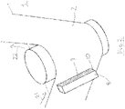
- Figure 2 shows an alternative embodiment of the invention wherein the oxygen injector outlet is a single wedge - shaped bar 8 with an aperture 9 located at the narrowing edge 10.
- the oxygen exits the outlet though aperture 9 directly onto the web sheet 2.
- the location of the oxygen injector is at the entrance of the web to the vacuum deposition chamber 1.
- the location of the injectors is optimised dependent on the aperture of the coater which defines the extent of the evaporated metal cloud.
- the injectors inject at or just before the boundary of the metal cloud.
- both the position of the injectors and the size of the aperture may be varied. Respective actuators may be provided to displace these as appropriate.
- Figure 3 shows a schematic side view of the vacuum coater. Two seals 11 and 12 can be seen either side of the main roller 3 immediately adjacent to it. The location of the deposition source 14 is shown below the roller 3.
- the oxygen injector 5 is closely contiguous with one of said seals and can be seen to be substantially tangential to the lowest mid-point of the roller 3 or slightly offset but parallel to the tangent as described in certain preceding embodiments.
- Figure 4 shows the same view including a static shield or a displaceable shutter 15 which, in use, prevents the oxygen injector nozzle from becoming blocked by deposits from the aluminium cloud.
- the shutter also acts to shield the deposition source to a greater or lesser extent.
- the shutter 15 is located at a position in which it extends past the oxygen injector. In this way it is able to prevent blockage of the nozzles.
- the oxygen is deposited on to the web sheet at its interface both immediately prior to and during the metal deposition within the vacuum chamber. This creates an oxygen rich metal oxide layer between the web surface and the remaining depth of the metal layer.
- the remaining depth of the metal layer is typically 10-60nm.
- the flow rate of oxygen is within the range of 300-700 scm 3 per minute per 100 mm of the web's width.
- the flow rate of oxygen is within the range of 300-500 scm 3 per minute per 100 mm of the web's width.
- the flow rate of oxygen may be within the range of 350-400scm 3 per minute per 100mm of the web's width.
- the amount of oxygen used in combination with the position of the oxygen injector has a negligible effect on the vacuum level.
- the invention can be used in conjunction with plasma pretreatment techniques to further increase metal adhesion.
- the plasma pre-treater may be provided in an unwind region prior to the film entering the deposition channel.
- the web comprises polyethylene terephthalate (PET).
- PET polyethylene terephthalate
- the web comprises biaxially oriented polypropylene (BOPP).
- BOPP biaxially oriented polypropylene
- the web comprises cast polypropylene (CPP).
- CPP cast polypropylene
- the flow rate of oxygen is within the range of 200-600 scm 3 per minute per 100mm of the web's width and the web comprises polyethylene terephthalate (PET).
- PET polyethylene terephthalate
- the web is coated to achieve an optical density (OD) of between 2.2 and 2.6 and the flow rate of oxygen is within the range of 200 and 400 scm 3 per minute per 100mm of the web's width.
- OD optical density
- the web is coated to achieve an optical density (OD) of between 2.2 and 2.6 and the flow rate of oxygen is within the range of 275 and 325 scm 3 per minute per 100mm of the web's width.
- OD optical density
- the web is coated to achieve an optical density (OD) of 2.4 and the flow rate of oxygen is 300 scm 3 per minute per 100mm of the web's width.
- the web is coated to achieve an optical density (OD) of between 2.6 and 3 and the flow rate of oxygen is within the range of 325 and 425 scm 3 per minute per 100mm of the web's width.
- the web is coated to achieve an optical density (OD) of 2.8 and the flow rate of oxygen is between 375 and 425 scm 3 per minute per 100mm of the web's width.
- the web is coated to achieve an optical density (OD) of between 3 and 3.4 and the flow rate of oxygen is within the range of 400 and 500 scm 3 per minute per 100mm of the web's width.
- OD optical density
- the web is coated to achieve an optical density (OD) of 3.2 and the flow rate of oxygen is between 450 and 500 scm 3 per minute per 100mm of the web's width.
- the flow rate of oxygen is within the range of 100-300 scm 3 per minute per 100mm of the web's width and the web comprises biaxially oriented polypropylene (BOPP).
- BOPP biaxially oriented polypropylene
- the web is coated to achieve an optical density (OD) of between 2 and 2.4 and the flow rate of oxygen is within the range of 150 and 200 scm 3 per minute per 100mm of the web's width.
- OD optical density
- the web is coated to achieve an optical density (OD) of 2.2 and the flow rate of oxygen is within the range of 150 and 200 scm 3 per minute per 100mm of the web's width.
- the flow rate of oxygen is within the range of 300-500 scm3 per minute per 100mm of the web's width and the web comprises cast polypropylene (CPP).
- CPP cast polypropylene
- the web is coated to achieve an optical density (OD) of between 2 and 2.4 and the flow rate of oxygen is within the range of 300 and 500 scm 3 per minute per 100mm of the web's width.
- OD optical density
- the web is coated to achieve an optical density (OD) of 2.2 and the flow rate of oxygen is within the range of 350 and 450 scm 3 per minute per 100mm of the web's width.
Landscapes
- Chemical & Material Sciences (AREA)
- Chemical Kinetics & Catalysis (AREA)
- Engineering & Computer Science (AREA)
- Materials Engineering (AREA)
- Mechanical Engineering (AREA)
- Metallurgy (AREA)
- Organic Chemistry (AREA)
- Physical Vapour Deposition (AREA)
- Laminated Bodies (AREA)
Priority Applications (1)
| Application Number | Priority Date | Filing Date | Title |
|---|---|---|---|
| EP21170452.3A EP3879000A1 (en) | 2015-03-10 | 2016-03-10 | Coated web, vacuum coater and methods |
Applications Claiming Priority (2)
| Application Number | Priority Date | Filing Date | Title |
|---|---|---|---|
| GB1504061.1A GB2536252B (en) | 2015-03-10 | 2015-03-10 | Method of operating a vacuum coater for coating a web |
| GBGB1511671.8A GB201511671D0 (en) | 2015-03-10 | 2015-07-03 | Improved Vacuum coater |
Related Child Applications (2)
| Application Number | Title | Priority Date | Filing Date |
|---|---|---|---|
| EP21170452.3A Division EP3879000A1 (en) | 2015-03-10 | 2016-03-10 | Coated web, vacuum coater and methods |
| EP21170452.3A Division-Into EP3879000A1 (en) | 2015-03-10 | 2016-03-10 | Coated web, vacuum coater and methods |
Publications (2)
| Publication Number | Publication Date |
|---|---|
| EP3067437A1 EP3067437A1 (en) | 2016-09-14 |
| EP3067437B1 true EP3067437B1 (en) | 2022-11-23 |
Family
ID=52998706
Family Applications (2)
| Application Number | Title | Priority Date | Filing Date |
|---|---|---|---|
| EP16159684.6A Active EP3067437B1 (en) | 2015-03-10 | 2016-03-10 | Improved vacuum coating method |
| EP21170452.3A Pending EP3879000A1 (en) | 2015-03-10 | 2016-03-10 | Coated web, vacuum coater and methods |
Family Applications After (1)
| Application Number | Title | Priority Date | Filing Date |
|---|---|---|---|
| EP21170452.3A Pending EP3879000A1 (en) | 2015-03-10 | 2016-03-10 | Coated web, vacuum coater and methods |
Country Status (4)
| Country | Link |
|---|---|
| EP (2) | EP3067437B1 (pl) |
| ES (1) | ES2934134T3 (pl) |
| GB (3) | GB2536252B (pl) |
| PL (1) | PL3067437T3 (pl) |
Cited By (1)
| Publication number | Priority date | Publication date | Assignee | Title |
|---|---|---|---|---|
| WO2024115618A1 (de) | 2022-12-01 | 2024-06-06 | Huhtamaki Flexible Packaging Germany Gmbh & Co. Kg | Laminat, insbesondere zur herstellung von verpackungen, verwendung des laminats zur herstellung einer verpackung sowie aus dem laminat hergestellte verpackung und verfahren zur herstellung des laminats |
Families Citing this family (2)
| Publication number | Priority date | Publication date | Assignee | Title |
|---|---|---|---|---|
| PL3419044T3 (pl) * | 2017-06-22 | 2023-06-12 | Bobst Manchester Limited | Maszyna do pepvd |
| CN111041446A (zh) * | 2019-12-31 | 2020-04-21 | 广东铭丰包装材料有限公司 | 一种镀铝机的送气装置 |
Citations (2)
| Publication number | Priority date | Publication date | Assignee | Title |
|---|---|---|---|---|
| JPS62228461A (ja) * | 1986-03-31 | 1987-10-07 | Toyo Metaraijingu Kk | 金属蒸着フイルムおよびその製造方法 |
| JP2009197340A (ja) * | 2008-02-19 | 2009-09-03 | Toray Ind Inc | 金銀糸用金属蒸着ポリエステルフィルムおよび金銀糸 |
Family Cites Families (21)
| Publication number | Priority date | Publication date | Assignee | Title |
|---|---|---|---|---|
| JPS5788531A (en) * | 1980-11-20 | 1982-06-02 | Matsushita Electric Ind Co Ltd | Manufacture for magnetic recording medium |
| JPS5927954A (ja) | 1982-08-10 | 1984-02-14 | Nippon Hodo Co Ltd | 舗装用アスフアルトの改質材料 |
| CA1235808A (en) * | 1984-03-22 | 1988-04-26 | Tetsuo Oka | Vertical magnetic recording medium and process for preparation thereof |
| JPS6126941A (ja) * | 1984-07-17 | 1986-02-06 | Mitsubishi Electric Corp | 磁気記録媒体の製造方法 |
| JPH0699798B2 (ja) * | 1985-10-29 | 1994-12-07 | 東洋メタライジング株式会社 | 透明ガス遮断性フイルムの製造方法 |
| JPH0798868B2 (ja) | 1992-03-26 | 1995-10-25 | 三菱化学株式会社 | 繊維強化ポリプロピレン樹脂シートの製造方法 |
| JP3331622B2 (ja) * | 1992-06-05 | 2002-10-07 | 東レ株式会社 | 透明ガスバリア性フィルムの製造方法 |
| JPH064862A (ja) * | 1992-06-23 | 1994-01-14 | Matsushita Electric Ind Co Ltd | 磁気記録媒体の製造方法 |
| JPH0798868A (ja) * | 1993-09-30 | 1995-04-11 | Kao Corp | 磁気記録媒体の製造装置 |
| JP3173549B2 (ja) * | 1994-06-17 | 2001-06-04 | 松下電器産業株式会社 | 磁気記録媒体の製造方法 |
| US5759710A (en) * | 1994-08-18 | 1998-06-02 | Matsushita Electric Industrial Co., Ltd. | Magnetic recording medium with a magnetic layer having a specific oxygen signal strength profile in the thickness direction |
| JPH1053868A (ja) * | 1996-08-07 | 1998-02-24 | Kao Corp | 薄膜形成装置 |
| JPH1091958A (ja) * | 1996-09-19 | 1998-04-10 | Kao Corp | 磁気記録媒体の製造方法 |
| JP3076774B2 (ja) * | 1997-05-29 | 2000-08-14 | 株式会社麗光 | 透明なバリアフィルムとその製造方法 |
| US6652998B2 (en) * | 2000-06-26 | 2003-11-25 | Jvc Victor Company Of Japan, Ltd. | Producing method of thin film magnetic tape and the thin film magnetic tape |
| EP1522606B1 (de) * | 2003-10-10 | 2009-12-09 | Fraunhofer-Gesellschaft zur Förderung der angewandten Forschung e.V. | Verfahren zur Beschichtung von bandförmigem Material mit schwarzem Aluminiumoxid |
| JP2007270251A (ja) * | 2006-03-31 | 2007-10-18 | Toray Ind Inc | 多層薄膜付き積層体の製造方法および製造装置 |
| JP5239483B2 (ja) * | 2008-04-28 | 2013-07-17 | 東レ株式会社 | 金属酸化物薄膜付きシートの製造方法および製造装置 |
| KR20140029470A (ko) * | 2011-04-29 | 2014-03-10 | 어플라이드 머티어리얼스, 인코포레이티드 | 코팅 프로세스에서 가요성 기판을 패시베이팅하기 위한 디바이스들 및 방법들 |
| JP2013189701A (ja) * | 2012-02-14 | 2013-09-26 | Tokyo Electron Ltd | 成膜装置 |
| JP2013234364A (ja) * | 2012-05-09 | 2013-11-21 | Mitsubishi Plastics Inc | ガスバリア性フィルムの製造方法 |
-
2015
- 2015-03-10 GB GB1504061.1A patent/GB2536252B/en active Active
- 2015-03-10 GB GB1801583.4A patent/GB2559685B/en active Active
- 2015-07-03 GB GBGB1511671.8A patent/GB201511671D0/en not_active Ceased
-
2016
- 2016-03-10 PL PL16159684.6T patent/PL3067437T3/pl unknown
- 2016-03-10 ES ES16159684T patent/ES2934134T3/es active Active
- 2016-03-10 EP EP16159684.6A patent/EP3067437B1/en active Active
- 2016-03-10 EP EP21170452.3A patent/EP3879000A1/en active Pending
Patent Citations (2)
| Publication number | Priority date | Publication date | Assignee | Title |
|---|---|---|---|---|
| JPS62228461A (ja) * | 1986-03-31 | 1987-10-07 | Toyo Metaraijingu Kk | 金属蒸着フイルムおよびその製造方法 |
| JP2009197340A (ja) * | 2008-02-19 | 2009-09-03 | Toray Ind Inc | 金銀糸用金属蒸着ポリエステルフィルムおよび金銀糸 |
Cited By (2)
| Publication number | Priority date | Publication date | Assignee | Title |
|---|---|---|---|---|
| WO2024115618A1 (de) | 2022-12-01 | 2024-06-06 | Huhtamaki Flexible Packaging Germany Gmbh & Co. Kg | Laminat, insbesondere zur herstellung von verpackungen, verwendung des laminats zur herstellung einer verpackung sowie aus dem laminat hergestellte verpackung und verfahren zur herstellung des laminats |
| WO2024115617A1 (de) | 2022-12-01 | 2024-06-06 | Huhtamaki Flexible Packaging Germany Gmbh & Co. Kg | Laminat, insbesondere zur herstellung von verpackungen, verwendung des laminats zur herstellung einer verpackung sowie aus dem laminat hergestellte verpackung und verfahren zur herstellung des laminats |
Also Published As
| Publication number | Publication date |
|---|---|
| EP3879000A1 (en) | 2021-09-15 |
| GB201511671D0 (en) | 2015-08-19 |
| GB2536252B (en) | 2018-10-10 |
| GB2536252A (en) | 2016-09-14 |
| GB201504061D0 (en) | 2015-04-22 |
| GB2559685A (en) | 2018-08-15 |
| GB201801583D0 (en) | 2018-03-14 |
| ES2934134T3 (es) | 2023-02-17 |
| EP3067437A1 (en) | 2016-09-14 |
| GB2559685B (en) | 2019-06-12 |
| PL3067437T3 (pl) | 2023-05-15 |
Similar Documents
| Publication | Publication Date | Title |
|---|---|---|
| EP3441503B1 (en) | Devices and methods for passivating a flexible substrate in a coating process | |
| EP3067437A1 (en) | Improved vacuum coater | |
| EP1797217A1 (de) | Verfahren und vorrichtung zum aufbringen einer elektrischen leitfähigen transparenten beschichtung auf ein substrat | |
| DE112011103584T5 (de) | Plasma-CVD-Gerät | |
| CN101688306B (zh) | 用于在共用等离子涂覆区沉积多种涂覆材料的装置与方法 | |
| EP2818572B1 (en) | Evaporation apparatus with gas supply | |
| EP3491161B1 (en) | Deposition apparatus | |
| KR101831291B1 (ko) | 금속증착장치 | |
| US20130149445A1 (en) | Method for producing a strong bond between a polymer substrate and an inorganic layer | |
| GB2527622A (en) | Vacuum coaters and methods of operating a vacuum coater | |
| KR102830873B1 (ko) | 원자층 증착 장치 | |
| US9368749B2 (en) | Patterned multilayered stack, and system and method for making the same | |
| EP2990502B1 (en) | Vacuum coaters and methods of operating a vacuum coater | |
| JP4366693B2 (ja) | バー塗布方法 | |
| US20080173388A1 (en) | Method for making an architectural laminate | |
| WO2022135724A1 (en) | Method of treating a coated flexible substrate for packaging applications | |
| KR101664099B1 (ko) | 도금 장치 및 도금 방법 | |
| KR20150037261A (ko) | 막 형성 장치 | |
| DE10113030A1 (de) | Plasmabeschichtungsverfahren und Vorrichtung zur Durchführung des Verfahrens | |
| KR20170138098A (ko) | 스퍼터링 증착장치 |
Legal Events
| Date | Code | Title | Description |
|---|---|---|---|
| PUAI | Public reference made under article 153(3) epc to a published international application that has entered the european phase |
Free format text: ORIGINAL CODE: 0009012 |
|
| AK | Designated contracting states |
Kind code of ref document: A1 Designated state(s): AL AT BE BG CH CY CZ DE DK EE ES FI FR GB GR HR HU IE IS IT LI LT LU LV MC MK MT NL NO PL PT RO RS SE SI SK SM TR |
|
| AX | Request for extension of the european patent |
Extension state: BA ME |
|
| STAA | Information on the status of an ep patent application or granted ep patent |
Free format text: STATUS: REQUEST FOR EXAMINATION WAS MADE |
|
| 17P | Request for examination filed |
Effective date: 20170314 |
|
| RBV | Designated contracting states (corrected) |
Designated state(s): AL AT BE BG CH CY CZ DE DK EE ES FI FR GB GR HR HU IE IS IT LI LT LU LV MC MK MT NL NO PL PT RO RS SE SI SK SM TR |
|
| STAA | Information on the status of an ep patent application or granted ep patent |
Free format text: STATUS: EXAMINATION IS IN PROGRESS |
|
| 17Q | First examination report despatched |
Effective date: 20190416 |
|
| GRAP | Despatch of communication of intention to grant a patent |
Free format text: ORIGINAL CODE: EPIDOSNIGR1 |
|
| STAA | Information on the status of an ep patent application or granted ep patent |
Free format text: STATUS: GRANT OF PATENT IS INTENDED |
|
| GRAS | Grant fee paid |
Free format text: ORIGINAL CODE: EPIDOSNIGR3 |
|
| INTG | Intention to grant announced |
Effective date: 20220915 |
|
| GRAA | (expected) grant |
Free format text: ORIGINAL CODE: 0009210 |
|
| STAA | Information on the status of an ep patent application or granted ep patent |
Free format text: STATUS: THE PATENT HAS BEEN GRANTED |
|
| AK | Designated contracting states |
Kind code of ref document: B1 Designated state(s): AL AT BE BG CH CY CZ DE DK EE ES FI FR GB GR HR HU IE IS IT LI LT LU LV MC MK MT NL NO PL PT RO RS SE SI SK SM TR |
|
| REG | Reference to a national code |
Ref country code: GB Ref legal event code: FG4D |
|
| REG | Reference to a national code |
Ref country code: CH Ref legal event code: EP |
|
| REG | Reference to a national code |
Ref country code: AT Ref legal event code: REF Ref document number: 1533182 Country of ref document: AT Kind code of ref document: T Effective date: 20221215 Ref country code: DE Ref legal event code: R096 Ref document number: 602016076434 Country of ref document: DE |
|
| REG | Reference to a national code |
Ref country code: RO Ref legal event code: EPE Ref country code: IE Ref legal event code: FG4D |
|
| REG | Reference to a national code |
Ref country code: ES Ref legal event code: FG2A Ref document number: 2934134 Country of ref document: ES Kind code of ref document: T3 Effective date: 20230217 |
|
| REG | Reference to a national code |
Ref country code: LT Ref legal event code: MG9D |
|
| REG | Reference to a national code |
Ref country code: NL Ref legal event code: MP Effective date: 20221123 |
|
| REG | Reference to a national code |
Ref country code: AT Ref legal event code: MK05 Ref document number: 1533182 Country of ref document: AT Kind code of ref document: T Effective date: 20221123 |
|
| PG25 | Lapsed in a contracting state [announced via postgrant information from national office to epo] |
Ref country code: SE Free format text: LAPSE BECAUSE OF FAILURE TO SUBMIT A TRANSLATION OF THE DESCRIPTION OR TO PAY THE FEE WITHIN THE PRESCRIBED TIME-LIMIT Effective date: 20221123 Ref country code: PT Free format text: LAPSE BECAUSE OF FAILURE TO SUBMIT A TRANSLATION OF THE DESCRIPTION OR TO PAY THE FEE WITHIN THE PRESCRIBED TIME-LIMIT Effective date: 20230323 Ref country code: NO Free format text: LAPSE BECAUSE OF FAILURE TO SUBMIT A TRANSLATION OF THE DESCRIPTION OR TO PAY THE FEE WITHIN THE PRESCRIBED TIME-LIMIT Effective date: 20230223 Ref country code: LT Free format text: LAPSE BECAUSE OF FAILURE TO SUBMIT A TRANSLATION OF THE DESCRIPTION OR TO PAY THE FEE WITHIN THE PRESCRIBED TIME-LIMIT Effective date: 20221123 Ref country code: FI Free format text: LAPSE BECAUSE OF FAILURE TO SUBMIT A TRANSLATION OF THE DESCRIPTION OR TO PAY THE FEE WITHIN THE PRESCRIBED TIME-LIMIT Effective date: 20221123 Ref country code: AT Free format text: LAPSE BECAUSE OF FAILURE TO SUBMIT A TRANSLATION OF THE DESCRIPTION OR TO PAY THE FEE WITHIN THE PRESCRIBED TIME-LIMIT Effective date: 20221123 |
|
| PG25 | Lapsed in a contracting state [announced via postgrant information from national office to epo] |
Ref country code: RS Free format text: LAPSE BECAUSE OF FAILURE TO SUBMIT A TRANSLATION OF THE DESCRIPTION OR TO PAY THE FEE WITHIN THE PRESCRIBED TIME-LIMIT Effective date: 20221123 Ref country code: LV Free format text: LAPSE BECAUSE OF FAILURE TO SUBMIT A TRANSLATION OF THE DESCRIPTION OR TO PAY THE FEE WITHIN THE PRESCRIBED TIME-LIMIT Effective date: 20221123 Ref country code: IS Free format text: LAPSE BECAUSE OF FAILURE TO SUBMIT A TRANSLATION OF THE DESCRIPTION OR TO PAY THE FEE WITHIN THE PRESCRIBED TIME-LIMIT Effective date: 20230323 Ref country code: HR Free format text: LAPSE BECAUSE OF FAILURE TO SUBMIT A TRANSLATION OF THE DESCRIPTION OR TO PAY THE FEE WITHIN THE PRESCRIBED TIME-LIMIT Effective date: 20221123 Ref country code: GR Free format text: LAPSE BECAUSE OF FAILURE TO SUBMIT A TRANSLATION OF THE DESCRIPTION OR TO PAY THE FEE WITHIN THE PRESCRIBED TIME-LIMIT Effective date: 20230224 |
|
| P01 | Opt-out of the competence of the unified patent court (upc) registered |
Effective date: 20230519 |
|
| PG25 | Lapsed in a contracting state [announced via postgrant information from national office to epo] |
Ref country code: NL Free format text: LAPSE BECAUSE OF FAILURE TO SUBMIT A TRANSLATION OF THE DESCRIPTION OR TO PAY THE FEE WITHIN THE PRESCRIBED TIME-LIMIT Effective date: 20221123 |
|
| PG25 | Lapsed in a contracting state [announced via postgrant information from national office to epo] |
Ref country code: SM Free format text: LAPSE BECAUSE OF FAILURE TO SUBMIT A TRANSLATION OF THE DESCRIPTION OR TO PAY THE FEE WITHIN THE PRESCRIBED TIME-LIMIT Effective date: 20221123 Ref country code: EE Free format text: LAPSE BECAUSE OF FAILURE TO SUBMIT A TRANSLATION OF THE DESCRIPTION OR TO PAY THE FEE WITHIN THE PRESCRIBED TIME-LIMIT Effective date: 20221123 Ref country code: DK Free format text: LAPSE BECAUSE OF FAILURE TO SUBMIT A TRANSLATION OF THE DESCRIPTION OR TO PAY THE FEE WITHIN THE PRESCRIBED TIME-LIMIT Effective date: 20221123 Ref country code: CZ Free format text: LAPSE BECAUSE OF FAILURE TO SUBMIT A TRANSLATION OF THE DESCRIPTION OR TO PAY THE FEE WITHIN THE PRESCRIBED TIME-LIMIT Effective date: 20221123 |
|
| REG | Reference to a national code |
Ref country code: DE Ref legal event code: R097 Ref document number: 602016076434 Country of ref document: DE |
|
| PG25 | Lapsed in a contracting state [announced via postgrant information from national office to epo] |
Ref country code: SK Free format text: LAPSE BECAUSE OF FAILURE TO SUBMIT A TRANSLATION OF THE DESCRIPTION OR TO PAY THE FEE WITHIN THE PRESCRIBED TIME-LIMIT Effective date: 20221123 Ref country code: AL Free format text: LAPSE BECAUSE OF FAILURE TO SUBMIT A TRANSLATION OF THE DESCRIPTION OR TO PAY THE FEE WITHIN THE PRESCRIBED TIME-LIMIT Effective date: 20221123 |
|
| PLBE | No opposition filed within time limit |
Free format text: ORIGINAL CODE: 0009261 |
|
| STAA | Information on the status of an ep patent application or granted ep patent |
Free format text: STATUS: NO OPPOSITION FILED WITHIN TIME LIMIT |
|
| PG25 | Lapsed in a contracting state [announced via postgrant information from national office to epo] |
Ref country code: MC Free format text: LAPSE BECAUSE OF FAILURE TO SUBMIT A TRANSLATION OF THE DESCRIPTION OR TO PAY THE FEE WITHIN THE PRESCRIBED TIME-LIMIT Effective date: 20221123 |
|
| REG | Reference to a national code |
Ref country code: CH Ref legal event code: PL |
|
| 26N | No opposition filed |
Effective date: 20230824 |
|
| PG25 | Lapsed in a contracting state [announced via postgrant information from national office to epo] |
Ref country code: SI Free format text: LAPSE BECAUSE OF FAILURE TO SUBMIT A TRANSLATION OF THE DESCRIPTION OR TO PAY THE FEE WITHIN THE PRESCRIBED TIME-LIMIT Effective date: 20221123 |
|
| REG | Reference to a national code |
Ref country code: BE Ref legal event code: MM Effective date: 20230331 |
|
| PG25 | Lapsed in a contracting state [announced via postgrant information from national office to epo] |
Ref country code: LU Free format text: LAPSE BECAUSE OF NON-PAYMENT OF DUE FEES Effective date: 20230310 |
|
| REG | Reference to a national code |
Ref country code: IE Ref legal event code: MM4A |
|
| PG25 | Lapsed in a contracting state [announced via postgrant information from national office to epo] |
Ref country code: LI Free format text: LAPSE BECAUSE OF NON-PAYMENT OF DUE FEES Effective date: 20230331 Ref country code: IE Free format text: LAPSE BECAUSE OF NON-PAYMENT OF DUE FEES Effective date: 20230310 Ref country code: FR Free format text: LAPSE BECAUSE OF NON-PAYMENT OF DUE FEES Effective date: 20230331 Ref country code: CH Free format text: LAPSE BECAUSE OF NON-PAYMENT OF DUE FEES Effective date: 20230331 |
|
| PG25 | Lapsed in a contracting state [announced via postgrant information from national office to epo] |
Ref country code: BE Free format text: LAPSE BECAUSE OF NON-PAYMENT OF DUE FEES Effective date: 20230331 |
|
| PG25 | Lapsed in a contracting state [announced via postgrant information from national office to epo] |
Ref country code: BG Free format text: LAPSE BECAUSE OF FAILURE TO SUBMIT A TRANSLATION OF THE DESCRIPTION OR TO PAY THE FEE WITHIN THE PRESCRIBED TIME-LIMIT Effective date: 20221123 |
|
| PG25 | Lapsed in a contracting state [announced via postgrant information from national office to epo] |
Ref country code: BG Free format text: LAPSE BECAUSE OF FAILURE TO SUBMIT A TRANSLATION OF THE DESCRIPTION OR TO PAY THE FEE WITHIN THE PRESCRIBED TIME-LIMIT Effective date: 20221123 |
|
| PGFP | Annual fee paid to national office [announced via postgrant information from national office to epo] |
Ref country code: ES Payment date: 20250410 Year of fee payment: 10 |
|
| PG25 | Lapsed in a contracting state [announced via postgrant information from national office to epo] |
Ref country code: CY Free format text: LAPSE BECAUSE OF FAILURE TO SUBMIT A TRANSLATION OF THE DESCRIPTION OR TO PAY THE FEE WITHIN THE PRESCRIBED TIME-LIMIT; INVALID AB INITIO Effective date: 20160310 |
|
| PG25 | Lapsed in a contracting state [announced via postgrant information from national office to epo] |
Ref country code: HU Free format text: LAPSE BECAUSE OF FAILURE TO SUBMIT A TRANSLATION OF THE DESCRIPTION OR TO PAY THE FEE WITHIN THE PRESCRIBED TIME-LIMIT; INVALID AB INITIO Effective date: 20160310 |
|
| PG25 | Lapsed in a contracting state [announced via postgrant information from national office to epo] |
Ref country code: TR Free format text: LAPSE BECAUSE OF FAILURE TO SUBMIT A TRANSLATION OF THE DESCRIPTION OR TO PAY THE FEE WITHIN THE PRESCRIBED TIME-LIMIT Effective date: 20221123 |
|
| PGFP | Annual fee paid to national office [announced via postgrant information from national office to epo] |
Ref country code: GB Payment date: 20260324 Year of fee payment: 11 |
|
| PGFP | Annual fee paid to national office [announced via postgrant information from national office to epo] |
Ref country code: DE Payment date: 20260319 Year of fee payment: 11 |
|
| PGFP | Annual fee paid to national office [announced via postgrant information from national office to epo] |
Ref country code: RO Payment date: 20260303 Year of fee payment: 11 Ref country code: IT Payment date: 20260324 Year of fee payment: 11 |
|
| PGFP | Annual fee paid to national office [announced via postgrant information from national office to epo] |
Ref country code: PL Payment date: 20260227 Year of fee payment: 11 |