EP3065990B1 - Fusspodest und arbeitstisch mit einem fusspodest - Google Patents
Fusspodest und arbeitstisch mit einem fusspodest Download PDFInfo
- Publication number
- EP3065990B1 EP3065990B1 EP14700856.9A EP14700856A EP3065990B1 EP 3065990 B1 EP3065990 B1 EP 3065990B1 EP 14700856 A EP14700856 A EP 14700856A EP 3065990 B1 EP3065990 B1 EP 3065990B1
- Authority
- EP
- European Patent Office
- Prior art keywords
- foot
- foot platform
- foot rest
- desk
- plate
- Prior art date
- Legal status (The legal status is an assumption and is not a legal conclusion. Google has not performed a legal analysis and makes no representation as to the accuracy of the status listed.)
- Active
Links
Images


Classifications
-
- A—HUMAN NECESSITIES
- A47—FURNITURE; DOMESTIC ARTICLES OR APPLIANCES; COFFEE MILLS; SPICE MILLS; SUCTION CLEANERS IN GENERAL
- A47B—TABLES; DESKS; OFFICE FURNITURE; CABINETS; DRAWERS; GENERAL DETAILS OF FURNITURE
- A47B83/00—Combinations comprising two or more pieces of furniture of different kinds
- A47B83/001—Office desks or work-stations combined with other pieces of furniture, e.g. work space management systems
-
- A—HUMAN NECESSITIES
- A47—FURNITURE; DOMESTIC ARTICLES OR APPLIANCES; COFFEE MILLS; SPICE MILLS; SUCTION CLEANERS IN GENERAL
- A47C—CHAIRS; SOFAS; BEDS
- A47C16/00—Stand-alone rests or supports for feet, legs, arms, back or head
- A47C16/02—Footstools; Foot-rests; Leg-rests
- A47C16/025—Footstools; Foot-rests; Leg-rests adjustable, swivelling, rocking
-
- B—PERFORMING OPERATIONS; TRANSPORTING
- B60—VEHICLES IN GENERAL
- B60N—SEATS SPECIALLY ADAPTED FOR VEHICLES; VEHICLE PASSENGER ACCOMMODATION NOT OTHERWISE PROVIDED FOR
- B60N3/00—Arrangements or adaptations of other passenger fittings, not otherwise provided for
- B60N3/06—Arrangements or adaptations of other passenger fittings, not otherwise provided for of footrests
- B60N3/063—Arrangements or adaptations of other passenger fittings, not otherwise provided for of footrests with adjustment systems
-
- B—PERFORMING OPERATIONS; TRANSPORTING
- B61—RAILWAYS
- B61C—LOCOMOTIVES; MOTOR RAILCARS
- B61C17/00—Arrangement or disposition of parts; Details or accessories not otherwise provided for; Use of control gear and control systems
- B61C17/04—Arrangement or disposition of driving cabins, footplates or engine rooms; Ventilation thereof
-
- A—HUMAN NECESSITIES
- A47—FURNITURE; DOMESTIC ARTICLES OR APPLIANCES; COFFEE MILLS; SPICE MILLS; SUCTION CLEANERS IN GENERAL
- A47B—TABLES; DESKS; OFFICE FURNITURE; CABINETS; DRAWERS; GENERAL DETAILS OF FURNITURE
- A47B2200/00—General construction of tables or desks
- A47B2200/0084—Accessories for tables or desks
- A47B2200/0097—Foot rest being part of desk
Definitions
- Such equipment includes a possibility of adjusting the height of the seat, so that the respective operator can put himself in an optimal position for performing work or operating a system or a vehicle.
- a special feature of places for driving vehicles is that, in addition to the ergonomic requirements, the view into the open is also subject to requirements. The relationship between the driver's eyes and windows that allow a view of the outside is not freely selectable. As a result, the seat height and the height of the control panel cannot be changed arbitrarily.
- a foot pedestal is often part of a particularly well ergonomically equipped workplace. Particularly in the case of workplaces with changing staffing, this simple version is insufficient because people have legs of different lengths. That is why foot platforms are common equipped so that they can be individually adjusted by the respective operator.
- the invention is based on the object of proposing a foot pedestal which can be easily and optimally adjusted with simple means.
- a major advantage of the foot pedestal according to the invention is seen in the fact that it can be operated comfortably with simple means, because by actuating the remotely operable locking device the effect of the spring on the foot set plate is released, whereby the foot set plate swings upwards until it passes through the feet of the respective operator is held in the desired, optimal pivot position; by releasing the locking device, the foot set plate is then fixed in this swivel position. This procedure is so little demanding that it can be carried out by an operator without significant distraction even during the actual work.
- the foot platform according to the invention does not require any auxiliary energy.
- the spring can be designed differently; it is considered to be particularly advantageous if the spring is a gas spring.
- the locking element can be designed like a snap or as a spring-loaded plunger.
- the latching means have a friction lining which is fastened to the housing in the pivoting direction of the foot set plate, and the locking device is a spring-loaded friction element in such an arrangement that it can be guided from the side against the friction lining.
- the locking device of the foot platform according to the invention advantageously has a Bowden cable because Bowden cables are widely used and can therefore be used inexpensively.
- the invention further relates to a work table of a work station with a foot pedestal and has the task of designing such a work table with regard to the foot pedestal so that the foot pedestal can be adjusted in the seat position of an operator in a convenient manner in the respectively desired position with respect to the foot support plate.
- the foot platform described above is positioned according to the invention below the work table and the locking device is fastened to the work table in an easily accessible manner at its end used by the foot set plate.
- This work table is advantageous insofar as an operator in a seated position occupies the foot pedestal in a simple manner by actuating the locking device under the action of the spring into a respectively optimal pivot position can set what can be done without interrupting work and without any significant distraction from work.
- the work table according to the invention can be used at different work stations, including operator stations of different types of vehicles. It is considered to be particularly advantageous if the work table is the control desk of a driver's cab of a rail vehicle and the foot pedestal is attached to the floor of the driver's cab as well as the locking device its end facing away from the pedestal is attached laterally at the front in the upper region of a niche of the operating console which accommodates the pedestal.
- the illustrated embodiment of a work table according to the invention is a control panel 1 of a rail vehicle, which is otherwise not shown.
- the control panel is equipped with two workstations, each with a seat 2; to gain a better insight is the one in the Figure 1 right seat removed.
- Each workplace is provided with a niche 3, which is located below the work desk 1.
- a foot platform 4 is accommodated or fastened in the niche 3.
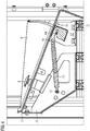
- the foot platform 4 has a pivotable means of a hinge 5 (see Figure 4 ) arranged foot plate 6.
- the foot set plate 6 is provided with a plurality of actuation switches 7 and 8 and 9 (cf. Fig.2 ) in the form of foot switches.
- the foot platform 4 has a housing 10 which is fastened in its lower region to a rail 11 of the rail vehicle.
- a gas spring 12 is attached to the housing 10 with its one end 13 pivotably below the foot plate 6; another end 14 of the gas spring 12 engages at the bottom of the foot set plate 6 and thus exerts a torque in the direction of the arrow 15 on the foot set plate 6.
- a perforated plate 17 with a plurality of holes 18 is fastened to the side of the housing 10 in the direction of the pivoting movement of the foot settling plate 6, so that it lies next to the foot settling plate 6 Figure 4 only schematically shown, spring-loaded locking element 19 of a locking device intervene in order to lock the foot set plate 6 in a found, optimal position.
- the locking element 19 can be part of a locking device in the form of a Bowden cable 20, such as Figure 2 shows.
- the Bowden cable 20 is connected at its end 21 remote from the foot set plate 6 to an actuating device 22, which is designed here as a shift lever.
Landscapes
- Engineering & Computer Science (AREA)
- Transportation (AREA)
- Mechanical Engineering (AREA)
- Automation & Control Theory (AREA)
- Passenger Equipment (AREA)
Description
- Aus der deutschen Gebrauchsmusterschrift
DE 200 00 612 U1 ist ein Sitzmöbel mit einem Hocker bekannt. Der Hocker weist die Merkmale des Oberbegriffs des Patentanspruchs 1 auf. - Aus der Internet-Veröffentlichung "http://www.chv-verkehrstechnik.de/de/leistungsangebot/fusspodeste.html" ist ein mechanisches Fußpodest bekannt, das hinsichtlich seiner Füßeabsetzplatte durch eine Gasfeder angetrieben ist und das eine Fernbetätigungseinrichtung aufweist, jedoch handelt es sich bei diesem bekannten Fußpodest um ein Podest mit einer schlittenartig unter Einsatz eines Stirnradgetriebes verstellbaren Füßeabsetzplatte.
- Für Arbeitsplätze, an denen eine Bedienungsperson arbeitsbedingt für eine längere Zeitdauer ununterbrochen auf einem Sitz verweilen muss, ist es wichtig, solche Arbeitsplätze so auszugestalten, dass sie ergonomisch optimal für die jeweilige Bedienungsperson eingerichtet sind. Zu einer solchen Ausrüstung gehört eine Möglichkeit zur Höhenanpassung des Sitzes, so dass sich die jeweilige Bedienungsperson in eine zur Verrichtung einer Arbeit oder einer Bedienung einer Anlage oder eines Fahrzeugs optimale Position versetzen kann. Eine Besonderheit bei Plätzen zum Führen von Fahrzeugen ist, dass neben den ergonomischen Anforderungen auch die Sicht ins Freie Anforderungen unterliegt. Der Bezug zwischen Augen des Fahrzeugführers und Fenstern, die den Blick ins Freie ermöglichen, ist nicht frei wählbar. Als Folge kann die Sitzhöhe und die Höhe des Bedienpults nicht beliebig verändert werden.
- Zu einer besonders gut ergonomisch ausgestatteten Ausrüstung des Arbeitsplatzes gehört häufig auch ein Fußpodest. Insbesondere bei Arbeitsplätzen mit wechselnder Besetzung ist dieses in einfacher Ausführung unzureichend, weil Menschen unterschiedlich lange Beine haben. Deshalb sind Fußpodeste häufig so ausgerüstet, dass sie von der jeweiligen Bedienungsperson individuell einstellbar sind.
- So ist es bekannt, ein Fußpodest für den Führerstand in einem Schienenfahrzeug mit einer schwenkbaren Füßeabsetzplatte auszurüsten, die in einer Schwenkposition, die zu der jeweiligen Bedienungsperson passt, von Hand eingestellt werden kann. Ein ähnliches Fußpodest ist durch die
EP-A1-0 008 753 bekannt. - Dies hat den Nachteil, dass sich die jeweilige Bedienungsperson ihre optimale Schwenkposition der Füßeabsetzplatte merken muss, um nach einer Arbeitsaufnahme im Führerstand das Fußpodest entsprechend einzustellen, oder probieren muss, bis eine optimale Schwenkposition der Füßeabsetzplatte erreicht ist.
- Der Erfindung liegt die Aufgabe zu Grunde, ein Fußpodest vorzuschlagen, das mit einfachen Mitteln bequem optimal einstellbar ist.
- Zur Lösung dieser Aufgabe ist ein Fußpodest mit den Merkmalen gemäß Patentanspruch 1 vorgesehen.
- Ein wesentlicher Vorteil des erfindungsgemäßen Fußpodestes wird darin gesehen, dass es mit einfachen Mitteln komfortabel betätigt werden kann, weil durch Betätigung der fernbetätigbaren Arretiereinrichtung die Wirkung der Feder auf die Füßeabsetzplatte freigegeben wird, wodurch die Füßeabsetzplatte soweit nach oben schwenkt, bis sie durch die Füße der jeweiligen Bedienungsperson in der gewünschten, optimalen Schwenkposition festgehalten wird; durch Freigabe der Arretiereinrichtung wird die Füßeabsetzplatte anschließend in dieser Schwenkposition festgelegt. Diese Prozedur ist so wenig anspruchsvoll, dass sie von einer Bedienungsperson ohne wesentliche Ablenkung auch während der eigentlichen Tätigkeit durchgeführt werden kann. Außerdem benötigt das erfindungsgemäße Fußpodest keine Hilfsenergie.
- Bei dem erfindungsgemäßen Fußpodest kann die Feder unterschiedlich ausgebildet sein; als besonders vorteilhaft wird es angesehen, wenn die Feder eine Gasfeder ist.
- Das Verriegelungselement kann nach Art eines Schnappers oder als federbelasteter Stößel ausgeführt sein.
- Als vorteilhaft erscheint es ferner, die Lochplatte seitlich neben der Füßeabsetzplatte an dem Gehäuse anzubringen, weil dies mit einem relativ geringen konstruktiven Aufwand zu verwirklichen ist.
- Ferner kann es vorteilhaft sein, wenn die Rastmittel einen Reibbelag aufweisen, der in Schwenkrichtung der Füßeabsetzplatte an dem Gehäuse befestigt ist, und die Arretiereinrichtung ein federbelastetes Reibelement in einer derartiges Anordnung ist, dass es von der Seite her gegen den Reibbelag führbar ist.
- Die Arretiereinrichtung des erfindungsgemäßen Fußpodestes weist vorteilhafterweise einen Bowdenzug auf, weil Bowdenzüge weit verbreitet sind und daher kostengünstig eingesetzt werden können.
- Die Erfindung betrifft ferner einen Arbeitstisch eines Arbeitsplatzes mit einem Fußpodest und stellt sich die Aufgabe, einen solchen Arbeitstisch hinsichtlich des Fußpodestes so auszugestalten, dass das Fußpodest in der Sitzposition einer Bedienungsperson in bequemer Weise in der jeweils gewünschten Position hinsichtlich der Füßeabsetzplatte einstellbar ist.
- Zur Lösung dieser Aufgabe ist erfindungsgemäß das oben beschriebene Fußpodest unterhalb des Arbeitstisches positioniert und die Arretierungseinrichtung ist an ihrem von der Füßeabsetzplatte angewendeten Ende an dem Arbeitstisch leicht zugänglich befestigt.
- Vorteilhaft ist dieser Arbeitstisch insofern, als eine Bedienungsperson in einer eingenommenen Sitzposition das Fußpodest in einfacher Weise durch Betätigung der Arretiereinrichtung unter der Wirkung der Feder in eine jeweils optimale Schwenkposition einstellen kann, was ohne Arbeitsunterbrechung und ohne nennenswerte Ablenkung von der Arbeit erfolgen kann.
- Der erfindungsgemäße Arbeitstisch kann an unterschiedlichen Arbeitsplätzen zum Einsatz gelangen, so auch bei Bedienplätzen von Fahrzeugen unterschiedlicher Art. Als besonders vorteilhaft wird es angesehen, wenn der Arbeitstisch das Bedienungspult eines Führerstand eines Schienenfahrzeugs ist und das Fußpodest am Boden des Führerstands befestigt ist sowie die Arretiereinrichtung mit ihrem von dem Fußpodest abgewendeten Ende seitlich vorn im oberen Bereich einer das Fußpodest aufnehmenden Nische des Bedienungspults befestigt ist.
- Zur weiteren Erläuterung der Erfindung ist in
- Figur 1
- eine Schrägansicht auf ein Ausführungsbeispiel eines Arbeitstisches in Form eines Bedienungspults im Führerstand eines Schienenfahrzeugs mit einem Ausführungsbeispiel des erfindungsgemäßen Fußpodests, in
- Figur 2
- eine weitere Ansicht des Arbeitstisches nach
Figur 1 mit abgenommenen Wandverkleidungen in einer Nische des Arbeitstisches, in - Figur 3
- eine Schrägansicht auf eine Lochplatte der Rastmittel und in
- Figur 4
- eine Seitenansicht auf dasselbe Ausführungsbeispiels des Fußpodests gezeigt.
- Bei dem in
Figur 1 gezeigten Ausführungsbeispiel eines erfindungsgemäßen Arbeitstisches handelt es sich um ein Bedienungspult 1 eines im Übrigen nicht dargestellten Schienenfahrzeugs. Wie dieFigur 1 im Einzelnen zeigt, ist das Bedienungspult mit zwei Arbeitsplätzen ausgerüstet, zu denen jeweils ein Sitz 2 gehört; zur Gewinnung eines besseren Einblicks ist der an dem in derFigur 1 rechten Arbeitsplatz befindliche Sitz entfernt. Jeder Arbeitsplatz ist mit einer Nische 3 versehen, die sich unterhalb des Arbeitspultes 1 befindet. In der Nische 3 ist ein Fußpodest 4 untergebracht bzw. befestigt. - Das Fußpodest 4 weist eine schwenkbar mittels eines Scharniers 5 (siehe
Fig.4 ) angeordnete Füßeabsetzplatte 6 auf. Die Füßeabsetzplatte 6 ist mit mehreren Betätigungsschaltern 7 und 8 sowie 9 (vgl.Fig.2 ) in Form von Fußschaltern ausgerüstet. - Wie insbesondere
Figur 4 zeigt, weist das Fußpodest 4 ein Gehäuse 10 auf, das in seinem unteren Bereich an einer Schiene 11 des Schienenfahrzeugs befestigt ist. Wie dieFigur 4 ferner zeigt, ist unterhalb der Füßeabsetzplatte 6 eine Gasfeder 12 am Gehäuse 10 mit ihrem einen Ende 13 schwenkbar befestigt; ein anderes Ende 14 der Gasfeder 12 greift unten an der Füßeabsetzplatte 6 an und übt somit auf die Füßeabsetzplatte 6 ein Drehmoment in Richtung des Pfeiles 15 aus. - Um die Wirkung der Gasfeder 12 zu kontrollieren, ist seitlich neben der Füßeabsetzplatte 6 eine Lochplatte 17 mit mehreren Löchern 18 am Gehäuse 10 in Richtung der Schwenkbewegung der Füßeabsetzplatte 6 befestigt, liegt also neben der Füßeabsetzplatte 6. In diese Löcher 18 kann ein in der
Figur 4 nur schematisch dargestelltes, federbelastetes Verriegelungselement 19 einer Arretiereinrichtung eingreifen, um die Füßeabsetzplatte 6 in einer gefundenen, optimalen Position zu arretieren. - Das Verriegelungselement 19 kann Bestandteil einer in Form eines Bowdenzuges 20 ausgeführten Arretiereinrichtung sein, wie
Figur 2 zeigt. Dabei ist der Bowdenzug 20 an seinem von der Füßeabsetzplatte 6 entfernten Ende 21 mit einer Betätigungseinrichtung 22 verbunden, die hier als Schalthebel ausgeführt ist.
Claims (7)
- Fußpodest (4) mit- einem schwenkbar gelagerten Fußabsetzelement, das sich an seiner Unterseite auf einer Feder (12) abstützt, mit- mechanischen Rastmitteln (17) zur Arretierung des Fußabsetzelements in einer Schwenkposition, und- einer fern betätigbaren mechanischen Arretiereinrichtung (19) an dem Fußabsetzelement zum Eingriff in die mechanischen Rastmittel (17),
dadurch gekennzeichnet, dass- das Fußabsetzelement eine Füßeabsetzplatte (6) ist, die schwenkbar an einem Gehäuse (10) des Fußpodests (4) gelagert ist,- die Rastmittel eine Lochplatte (17) aufweisen, die in Schwenkrichtung der Füßeabsetzplatte (6) an dem Gehäuse (10) befestigt ist, und- die Arretiereinrichtung ein federbelastetes Verriegelungselement (19) in einer derartigen Anordnung an der Füßeabsetzplatte (6) enthält, dass es von der Seite her in die Löcher (18) der Lochplatte (17) einführbar ist. - Fußpodest nach Anspruch 1,
dadurch gekennzeichnet, dass
die Feder eine Gasfeder (12) ist. - Fußpodest nach Anspruch 1 oder 2,
dadurch gekennzeichnet, dass
die Lochplatte (17) seitlich neben der Füßeabsetzplatte (6) an dem Gehäuse (10) angebracht ist. - Fußpodest nach einem der voranstehenden Ansprüche,
dadurch gekennzeichnet, dass
die Rastmittel einen Reibbelag aufweisen, der in Schwenkrichtung der Füßeabsetzplatte an dem Gehäuse befestigt ist, und die Arretiereinrichtung ein federbelastetes Reibelement in einer derartiges Anordnung ist, dass es von der Seite her gegen den Reibbelag führbar ist. - Fußpodest nach einem der voranstehenden Ansprüche,
dadurch gekennzeichnet, dass
die Arretiereinrichtung einen Bowdenzug (20) weist. - Arbeitstisch (1) eines Arbeitsplatzes mit einem Fußpodest (4) nach einem der vorangehenden Ansprüche,
dadurch gekennzeichnet, dass
das Fußpodest (4) unterhalb des Arbeitstisches (1) positioniert ist und die Arretiereinrichtung (22) an ihrem von der Füßeabsetzplatte abgewendeten Ende an dem Arbeitstisch (1) leicht zugänglich befestigt ist. - Arbeitstisch nach Anspruch 6,
dadurch gekennzeichnet, dass
der Arbeitstisch das Bedienungspult (1) eines Führerstands eines Schienenfahrzeugs ist und
das Fußpodest (4) am Boden des Führerstands befestigt ist und die Arretiereinrichtung (22) mit ihrem von dem Fußpodest (4) abgewendeten Ende (21) seitlich vorn im oberen Bereich einer das Fußpodest (4) aufnehmenden Nische (3) des Bedienungspults (1) befestigt ist.
Priority Applications (1)
| Application Number | Priority Date | Filing Date | Title |
|---|---|---|---|
| PL14700856T PL3065990T3 (pl) | 2014-01-15 | 2014-01-15 | Podest dla stóp i stół roboczy z podestem dla stóp |
Applications Claiming Priority (1)
| Application Number | Priority Date | Filing Date | Title |
|---|---|---|---|
| PCT/EP2014/050688 WO2015106807A1 (de) | 2014-01-15 | 2014-01-15 | Fusspodest und arbeitstisch mit einem fusspodest |
Publications (2)
| Publication Number | Publication Date |
|---|---|
| EP3065990A1 EP3065990A1 (de) | 2016-09-14 |
| EP3065990B1 true EP3065990B1 (de) | 2019-12-25 |
Family
ID=49998253
Family Applications (1)
| Application Number | Title | Priority Date | Filing Date |
|---|---|---|---|
| EP14700856.9A Active EP3065990B1 (de) | 2014-01-15 | 2014-01-15 | Fusspodest und arbeitstisch mit einem fusspodest |
Country Status (5)
| Country | Link |
|---|---|
| US (1) | US9924795B2 (de) |
| EP (1) | EP3065990B1 (de) |
| ES (1) | ES2776164T3 (de) |
| PL (1) | PL3065990T3 (de) |
| WO (1) | WO2015106807A1 (de) |
Cited By (1)
| Publication number | Priority date | Publication date | Assignee | Title |
|---|---|---|---|---|
| EP4029756A1 (de) | 2021-01-15 | 2022-07-20 | TEVER Technik GmbH & Co. KG | Fusspodest mit höhenverstellbarer trittplatte zum führen eines fahrzeugs |
Families Citing this family (6)
| Publication number | Priority date | Publication date | Assignee | Title |
|---|---|---|---|---|
| US8002332B2 (en) | 2007-01-30 | 2011-08-23 | Zephyros, Inc. | Structural mounting insert |
| CN108202652B (zh) * | 2016-12-16 | 2019-06-11 | 北汽福田汽车股份有限公司 | 一种可调式歇脚板总成及具有其的车辆 |
| JP6933485B2 (ja) * | 2017-03-31 | 2021-09-08 | 株式会社総合車両製作所 | 鉄道車両の運転台構造及び運転台の構築方法 |
| CN107901928B (zh) * | 2017-11-08 | 2020-03-06 | 中车长春轨道客车股份有限公司 | 一种城市轨道车辆可调节式司机脚踏 |
| DE102018207035A1 (de) * | 2018-05-07 | 2019-11-07 | Siemens Aktiengesellschaft | Modulares Fußpodest für einen Führerstand eines Schienenfahrzeugs |
| CN113665598B (zh) * | 2020-05-13 | 2023-01-24 | 中车唐山机车车辆有限公司 | 用于脚踏装置的按钮组件,脚踏装置及轨道列车 |
Family Cites Families (15)
| Publication number | Priority date | Publication date | Assignee | Title |
|---|---|---|---|---|
| US640891A (en) * | 1899-10-19 | 1900-01-09 | Mamie G Read | Footboard for vehicles. |
| US2528331A (en) * | 1948-12-24 | 1950-10-31 | Alfred B Bell | Tiltably adjustable foot and leg rest |
| US2566498A (en) * | 1950-08-25 | 1951-09-04 | Joseph A Revercomb | Leg and foot rest |
| DE1810771A1 (de) * | 1968-11-25 | 1970-05-27 | Dr Robert Gaertner | Vorrichtung zum Hochlegen der Beine |
| US3784135A (en) * | 1972-03-07 | 1974-01-08 | Eastman Kodak Co | Elevation mechanism |
| DE2838654C2 (de) | 1978-09-05 | 1982-12-09 | Alfred 8000 München Lemmer | Fußstütze |
| DE7929349U1 (de) | 1979-10-17 | 1980-03-06 | C. & H. Leuthaeusser Inh. Hilmar Leuthaeusser, 8631 Wiesenfeld | Hoehenverstellbare fusstuetze |
| US5374102A (en) * | 1993-03-30 | 1994-12-20 | Baultar Inc. | Chair assembly for vehicle |
| JPH09263168A (ja) * | 1996-01-23 | 1997-10-07 | Araco Corp | 足置台 |
| DE19615532C1 (de) | 1996-04-19 | 1997-06-19 | Bosch Gmbh Robert | Höhenverstellbare Fußauflage, insbesondere für Montagetische |
| DE20000612U1 (de) | 2000-01-15 | 2000-03-30 | Frank, Wolfgang, 71540 Murrhardt | Sitzmöbel |
| FR2960834A1 (fr) * | 2010-06-04 | 2011-12-09 | Peugeot Citroen Automobiles Sa | Repose pied integre dans le plancher d'un vehicule automobile |
| US8757580B2 (en) * | 2010-11-09 | 2014-06-24 | Tever Technik GmbH & Co. KG. | Height-adjustable pedestal |
| US20130220168A1 (en) | 2010-11-09 | 2013-08-29 | Tever Technik Vertriebs- und Beteiligungs-GmbH & Co. Beratungs KG | Height-Adjustable Pedestal for a Vehicle |
| DE102012216561B3 (de) | 2012-09-17 | 2013-12-24 | GSI Manufaktur GmbH | Fußstütze für ein Schienenfahrzeug |
-
2014
- 2014-01-15 ES ES14700856T patent/ES2776164T3/es active Active
- 2014-01-15 EP EP14700856.9A patent/EP3065990B1/de active Active
- 2014-01-15 PL PL14700856T patent/PL3065990T3/pl unknown
- 2014-01-15 US US15/111,832 patent/US9924795B2/en not_active Expired - Fee Related
- 2014-01-15 WO PCT/EP2014/050688 patent/WO2015106807A1/de not_active Ceased
Non-Patent Citations (1)
| Title |
|---|
| None * |
Cited By (2)
| Publication number | Priority date | Publication date | Assignee | Title |
|---|---|---|---|---|
| EP4029756A1 (de) | 2021-01-15 | 2022-07-20 | TEVER Technik GmbH & Co. KG | Fusspodest mit höhenverstellbarer trittplatte zum führen eines fahrzeugs |
| DE102021005953A1 (de) | 2021-01-15 | 2022-07-21 | TE-V-ER Technik GmbH & Co. KG | Fußpodest mit höhenverstellbarer Trittplatte zum Führen eines Fahrzeugs |
Also Published As
| Publication number | Publication date |
|---|---|
| ES2776164T3 (es) | 2020-07-29 |
| EP3065990A1 (de) | 2016-09-14 |
| PL3065990T3 (pl) | 2020-06-29 |
| WO2015106807A1 (de) | 2015-07-23 |
| US9924795B2 (en) | 2018-03-27 |
| US20160338490A1 (en) | 2016-11-24 |
Similar Documents
| Publication | Publication Date | Title |
|---|---|---|
| WO2015106807A1 (de) | Fusspodest und arbeitstisch mit einem fusspodest | |
| AT12802U1 (de) | Haltevorrichtung für einen baulaser | |
| DE10322795B3 (de) | Sitzmöbel mit ausschwenkbarer Fußstütze | |
| EP3764844B1 (de) | Stuhlführung | |
| DE102005029235B4 (de) | Armlehne für einen Fahrzeugsitz und Fahrzeugsitz | |
| DE202009002535U1 (de) | Schwimmbeckenüberdachung | |
| EP0401465A2 (de) | Küchenarbeitseinheit | |
| DE102011109668A1 (de) | Sitzmöbel mit verstellbarer Kopfstütze | |
| DE102019133319A1 (de) | Unterflurinstallationsbauteil | |
| AT11940U1 (de) | Vorrichtung zum steuern von arbeitsgeräten | |
| EP2941148B1 (de) | Korpuspositionierung bei einem möbelmodul | |
| EP2200900B1 (de) | Arbeitsstation zur integration in ein luftfahrzeug, insbesondere helikopter | |
| DE102008018929A1 (de) | Freistehende Bedienstelle zur Steuerung eines Bearbeitungszentrums | |
| DE69818616T2 (de) | Anordnung für einen ausnehmbaren und in Längsrichtung verstellbaren Sitz im Innenraum eines Kraftfahrzeuges | |
| DE10244328A1 (de) | Verfahrbares Tischmodul für ein Fahrzeug, insbesondere für ein Kraftfahrzeug | |
| DE202011106262U1 (de) | Duschsitz | |
| EP1736393B1 (de) | Tragbock, insbesondere für Langmaterial | |
| DE102009056524B4 (de) | Stehplatz-Sitzplatz-Kombination | |
| DE102010020561A1 (de) | Verstellvorrichtung zum Verstellen einer Rückenlehne eines Fahrzeugssitzes | |
| DE10357162B4 (de) | Sitz-Vorrichtung | |
| DE102008040509A1 (de) | Duschvorrichtung | |
| DE10137386C1 (de) | Sicherheitsvorrichtung für Armaturen | |
| DE202015102277U1 (de) | Befestigungselement | |
| DE102022005080A1 (de) | Einrichtung zur Unterstützung eines Operateurs | |
| DE102023112884A1 (de) | Technik zur Ausstattung einer Nutzfahrzeugkabine mit mehreren Einrichtungsgegenständen |
Legal Events
| Date | Code | Title | Description |
|---|---|---|---|
| PUAI | Public reference made under article 153(3) epc to a published international application that has entered the european phase |
Free format text: ORIGINAL CODE: 0009012 |
|
| 17P | Request for examination filed |
Effective date: 20160606 |
|
| AK | Designated contracting states |
Kind code of ref document: A1 Designated state(s): AL AT BE BG CH CY CZ DE DK EE ES FI FR GB GR HR HU IE IS IT LI LT LU LV MC MK MT NL NO PL PT RO RS SE SI SK SM TR |
|
| AX | Request for extension of the european patent |
Extension state: BA ME |
|
| DAX | Request for extension of the european patent (deleted) | ||
| RAP1 | Party data changed (applicant data changed or rights of an application transferred) |
Owner name: SIEMENS AKTIENGESELLSCHAFT |
|
| RAP1 | Party data changed (applicant data changed or rights of an application transferred) |
Owner name: SIEMENS MOBILITY GMBH |
|
| GRAP | Despatch of communication of intention to grant a patent |
Free format text: ORIGINAL CODE: EPIDOSNIGR1 |
|
| STAA | Information on the status of an ep patent application or granted ep patent |
Free format text: STATUS: GRANT OF PATENT IS INTENDED |
|
| INTG | Intention to grant announced |
Effective date: 20190827 |
|
| GRAS | Grant fee paid |
Free format text: ORIGINAL CODE: EPIDOSNIGR3 |
|
| GRAA | (expected) grant |
Free format text: ORIGINAL CODE: 0009210 |
|
| STAA | Information on the status of an ep patent application or granted ep patent |
Free format text: STATUS: THE PATENT HAS BEEN GRANTED |
|
| AK | Designated contracting states |
Kind code of ref document: B1 Designated state(s): AL AT BE BG CH CY CZ DE DK EE ES FI FR GB GR HR HU IE IS IT LI LT LU LV MC MK MT NL NO PL PT RO RS SE SI SK SM TR |
|
| REG | Reference to a national code |
Ref country code: GB Ref legal event code: FG4D Free format text: NOT ENGLISH |
|
| REG | Reference to a national code |
Ref country code: CH Ref legal event code: EP |
|
| REG | Reference to a national code |
Ref country code: AT Ref legal event code: REF Ref document number: 1216818 Country of ref document: AT Kind code of ref document: T Effective date: 20200115 |
|
| REG | Reference to a national code |
Ref country code: DE Ref legal event code: R096 Ref document number: 502014013324 Country of ref document: DE |
|
| REG | Reference to a national code |
Ref country code: IE Ref legal event code: FG4D Free format text: LANGUAGE OF EP DOCUMENT: GERMAN |
|
| REG | Reference to a national code |
Ref country code: CH Ref legal event code: NV Representative=s name: SIEMENS SCHWEIZ AG, CH |
|
| REG | Reference to a national code |
Ref country code: NL Ref legal event code: MP Effective date: 20191225 |
|
| PG25 | Lapsed in a contracting state [announced via postgrant information from national office to epo] |
Ref country code: LV Free format text: LAPSE BECAUSE OF FAILURE TO SUBMIT A TRANSLATION OF THE DESCRIPTION OR TO PAY THE FEE WITHIN THE PRESCRIBED TIME-LIMIT Effective date: 20191225 Ref country code: SE Free format text: LAPSE BECAUSE OF FAILURE TO SUBMIT A TRANSLATION OF THE DESCRIPTION OR TO PAY THE FEE WITHIN THE PRESCRIBED TIME-LIMIT Effective date: 20191225 Ref country code: LT Free format text: LAPSE BECAUSE OF FAILURE TO SUBMIT A TRANSLATION OF THE DESCRIPTION OR TO PAY THE FEE WITHIN THE PRESCRIBED TIME-LIMIT Effective date: 20191225 Ref country code: GR Free format text: LAPSE BECAUSE OF FAILURE TO SUBMIT A TRANSLATION OF THE DESCRIPTION OR TO PAY THE FEE WITHIN THE PRESCRIBED TIME-LIMIT Effective date: 20200326 Ref country code: NO Free format text: LAPSE BECAUSE OF FAILURE TO SUBMIT A TRANSLATION OF THE DESCRIPTION OR TO PAY THE FEE WITHIN THE PRESCRIBED TIME-LIMIT Effective date: 20200325 Ref country code: FI Free format text: LAPSE BECAUSE OF FAILURE TO SUBMIT A TRANSLATION OF THE DESCRIPTION OR TO PAY THE FEE WITHIN THE PRESCRIBED TIME-LIMIT Effective date: 20191225 Ref country code: BG Free format text: LAPSE BECAUSE OF FAILURE TO SUBMIT A TRANSLATION OF THE DESCRIPTION OR TO PAY THE FEE WITHIN THE PRESCRIBED TIME-LIMIT Effective date: 20200325 |
|
| REG | Reference to a national code |
Ref country code: LT Ref legal event code: MG4D |
|
| PG25 | Lapsed in a contracting state [announced via postgrant information from national office to epo] |
Ref country code: HR Free format text: LAPSE BECAUSE OF FAILURE TO SUBMIT A TRANSLATION OF THE DESCRIPTION OR TO PAY THE FEE WITHIN THE PRESCRIBED TIME-LIMIT Effective date: 20191225 Ref country code: RS Free format text: LAPSE BECAUSE OF FAILURE TO SUBMIT A TRANSLATION OF THE DESCRIPTION OR TO PAY THE FEE WITHIN THE PRESCRIBED TIME-LIMIT Effective date: 20191225 |
|
| PG25 | Lapsed in a contracting state [announced via postgrant information from national office to epo] |
Ref country code: AL Free format text: LAPSE BECAUSE OF FAILURE TO SUBMIT A TRANSLATION OF THE DESCRIPTION OR TO PAY THE FEE WITHIN THE PRESCRIBED TIME-LIMIT Effective date: 20191225 |
|
| REG | Reference to a national code |
Ref country code: ES Ref legal event code: FG2A Ref document number: 2776164 Country of ref document: ES Kind code of ref document: T3 Effective date: 20200729 |
|
| PG25 | Lapsed in a contracting state [announced via postgrant information from national office to epo] |
Ref country code: RO Free format text: LAPSE BECAUSE OF FAILURE TO SUBMIT A TRANSLATION OF THE DESCRIPTION OR TO PAY THE FEE WITHIN THE PRESCRIBED TIME-LIMIT Effective date: 20191225 Ref country code: EE Free format text: LAPSE BECAUSE OF FAILURE TO SUBMIT A TRANSLATION OF THE DESCRIPTION OR TO PAY THE FEE WITHIN THE PRESCRIBED TIME-LIMIT Effective date: 20191225 Ref country code: NL Free format text: LAPSE BECAUSE OF FAILURE TO SUBMIT A TRANSLATION OF THE DESCRIPTION OR TO PAY THE FEE WITHIN THE PRESCRIBED TIME-LIMIT Effective date: 20191225 Ref country code: PT Free format text: LAPSE BECAUSE OF FAILURE TO SUBMIT A TRANSLATION OF THE DESCRIPTION OR TO PAY THE FEE WITHIN THE PRESCRIBED TIME-LIMIT Effective date: 20200520 |
|
| PG25 | Lapsed in a contracting state [announced via postgrant information from national office to epo] |
Ref country code: IS Free format text: LAPSE BECAUSE OF FAILURE TO SUBMIT A TRANSLATION OF THE DESCRIPTION OR TO PAY THE FEE WITHIN THE PRESCRIBED TIME-LIMIT Effective date: 20200425 Ref country code: SK Free format text: LAPSE BECAUSE OF FAILURE TO SUBMIT A TRANSLATION OF THE DESCRIPTION OR TO PAY THE FEE WITHIN THE PRESCRIBED TIME-LIMIT Effective date: 20191225 Ref country code: SM Free format text: LAPSE BECAUSE OF FAILURE TO SUBMIT A TRANSLATION OF THE DESCRIPTION OR TO PAY THE FEE WITHIN THE PRESCRIBED TIME-LIMIT Effective date: 20191225 |
|
| REG | Reference to a national code |
Ref country code: DE Ref legal event code: R097 Ref document number: 502014013324 Country of ref document: DE |
|
| PG25 | Lapsed in a contracting state [announced via postgrant information from national office to epo] |
Ref country code: MC Free format text: LAPSE BECAUSE OF FAILURE TO SUBMIT A TRANSLATION OF THE DESCRIPTION OR TO PAY THE FEE WITHIN THE PRESCRIBED TIME-LIMIT Effective date: 20191225 |
|
| REG | Reference to a national code |
Ref country code: BE Ref legal event code: MM Effective date: 20200131 |
|
| PG25 | Lapsed in a contracting state [announced via postgrant information from national office to epo] |
Ref country code: DK Free format text: LAPSE BECAUSE OF FAILURE TO SUBMIT A TRANSLATION OF THE DESCRIPTION OR TO PAY THE FEE WITHIN THE PRESCRIBED TIME-LIMIT Effective date: 20191225 Ref country code: LU Free format text: LAPSE BECAUSE OF NON-PAYMENT OF DUE FEES Effective date: 20200115 |
|
| PLBE | No opposition filed within time limit |
Free format text: ORIGINAL CODE: 0009261 |
|
| STAA | Information on the status of an ep patent application or granted ep patent |
Free format text: STATUS: NO OPPOSITION FILED WITHIN TIME LIMIT |
|
| PG25 | Lapsed in a contracting state [announced via postgrant information from national office to epo] |
Ref country code: SI Free format text: LAPSE BECAUSE OF FAILURE TO SUBMIT A TRANSLATION OF THE DESCRIPTION OR TO PAY THE FEE WITHIN THE PRESCRIBED TIME-LIMIT Effective date: 20191225 Ref country code: BE Free format text: LAPSE BECAUSE OF NON-PAYMENT OF DUE FEES Effective date: 20200131 |
|
| 26N | No opposition filed |
Effective date: 20200928 |
|
| PG25 | Lapsed in a contracting state [announced via postgrant information from national office to epo] |
Ref country code: IE Free format text: LAPSE BECAUSE OF NON-PAYMENT OF DUE FEES Effective date: 20200115 |
|
| REG | Reference to a national code |
Ref country code: AT Ref legal event code: MM01 Ref document number: 1216818 Country of ref document: AT Kind code of ref document: T Effective date: 20200115 |
|
| GBPC | Gb: european patent ceased through non-payment of renewal fee |
Effective date: 20200325 |
|
| PG25 | Lapsed in a contracting state [announced via postgrant information from national office to epo] |
Ref country code: GB Free format text: LAPSE BECAUSE OF NON-PAYMENT OF DUE FEES Effective date: 20200325 |
|
| PG25 | Lapsed in a contracting state [announced via postgrant information from national office to epo] |
Ref country code: AT Free format text: LAPSE BECAUSE OF NON-PAYMENT OF DUE FEES Effective date: 20200115 |
|
| PG25 | Lapsed in a contracting state [announced via postgrant information from national office to epo] |
Ref country code: TR Free format text: LAPSE BECAUSE OF FAILURE TO SUBMIT A TRANSLATION OF THE DESCRIPTION OR TO PAY THE FEE WITHIN THE PRESCRIBED TIME-LIMIT Effective date: 20191225 Ref country code: MT Free format text: LAPSE BECAUSE OF FAILURE TO SUBMIT A TRANSLATION OF THE DESCRIPTION OR TO PAY THE FEE WITHIN THE PRESCRIBED TIME-LIMIT Effective date: 20191225 Ref country code: CY Free format text: LAPSE BECAUSE OF FAILURE TO SUBMIT A TRANSLATION OF THE DESCRIPTION OR TO PAY THE FEE WITHIN THE PRESCRIBED TIME-LIMIT Effective date: 20191225 |
|
| PG25 | Lapsed in a contracting state [announced via postgrant information from national office to epo] |
Ref country code: MK Free format text: LAPSE BECAUSE OF FAILURE TO SUBMIT A TRANSLATION OF THE DESCRIPTION OR TO PAY THE FEE WITHIN THE PRESCRIBED TIME-LIMIT Effective date: 20191225 |
|
| PGFP | Annual fee paid to national office [announced via postgrant information from national office to epo] |
Ref country code: PL Payment date: 20240104 Year of fee payment: 11 Ref country code: IT Payment date: 20240124 Year of fee payment: 11 |
|
| PGFP | Annual fee paid to national office [announced via postgrant information from national office to epo] |
Ref country code: CH Payment date: 20240408 Year of fee payment: 11 |
|
| REG | Reference to a national code |
Ref country code: DE Ref legal event code: R081 Ref document number: 502014013324 Country of ref document: DE Owner name: SIEMENS MOBILITY GMBH, DE Free format text: FORMER OWNER: SIEMENS MOBILITY GMBH, 81739 MUENCHEN, DE |
|
| REG | Reference to a national code |
Ref country code: CH Ref legal event code: PL |
|
| PG25 | Lapsed in a contracting state [announced via postgrant information from national office to epo] |
Ref country code: CH Free format text: LAPSE BECAUSE OF NON-PAYMENT OF DUE FEES Effective date: 20250131 |
|
| PG25 | Lapsed in a contracting state [announced via postgrant information from national office to epo] |
Ref country code: IT Free format text: LAPSE BECAUSE OF NON-PAYMENT OF DUE FEES Effective date: 20250115 |
|
| PGFP | Annual fee paid to national office [announced via postgrant information from national office to epo] |
Ref country code: DE Payment date: 20260320 Year of fee payment: 13 |
|
| PGFP | Annual fee paid to national office [announced via postgrant information from national office to epo] |
Ref country code: FR Payment date: 20260122 Year of fee payment: 13 |
|
| PGFP | Annual fee paid to national office [announced via postgrant information from national office to epo] |
Ref country code: CZ Payment date: 20260109 Year of fee payment: 13 |
|
| PGFP | Annual fee paid to national office [announced via postgrant information from national office to epo] |
Ref country code: ES Payment date: 20260420 Year of fee payment: 13 |
|
| PG25 | Lapsed in a contracting state [announced via postgrant information from national office to epo] |
Ref country code: PL Free format text: LAPSE BECAUSE OF NON-PAYMENT OF DUE FEES Effective date: 20250115 |