EP3056321B1 - Loading/unloading robot - Google Patents
Loading/unloading robot Download PDFInfo
- Publication number
- EP3056321B1 EP3056321B1 EP16162163.6A EP16162163A EP3056321B1 EP 3056321 B1 EP3056321 B1 EP 3056321B1 EP 16162163 A EP16162163 A EP 16162163A EP 3056321 B1 EP3056321 B1 EP 3056321B1
- Authority
- EP
- European Patent Office
- Prior art keywords
- loading
- unloading
- arm
- head portion
- rotational axis
- Prior art date
- Legal status (The legal status is an assumption and is not a legal conclusion. Google has not performed a legal analysis and makes no representation as to the accuracy of the status listed.)
- Active
Links
Images
Classifications
-
- H—ELECTRICITY
- H10—SEMICONDUCTOR DEVICES; ELECTRIC SOLID-STATE DEVICES NOT OTHERWISE PROVIDED FOR
- H10P—GENERIC PROCESSES OR APPARATUS FOR THE MANUFACTURE OR TREATMENT OF DEVICES COVERED BY CLASS H10
- H10P72/00—Handling or holding of wafers, substrates or devices during manufacture or treatment thereof
- H10P72/30—Handling or holding of wafers, substrates or devices during manufacture or treatment thereof for conveying, e.g. between different workstations
- H10P72/33—Handling or holding of wafers, substrates or devices during manufacture or treatment thereof for conveying, e.g. between different workstations into and out of processing chamber
- H10P72/3302—Mechanical parts of transfer devices
-
- B—PERFORMING OPERATIONS; TRANSPORTING
- B25—HAND TOOLS; PORTABLE POWER-DRIVEN TOOLS; MANIPULATORS
- B25J—MANIPULATORS; CHAMBERS PROVIDED WITH MANIPULATION DEVICES
- B25J18/00—Arms
- B25J18/02—Arms extensible
- B25J18/04—Arms extensible rotatable
-
- B—PERFORMING OPERATIONS; TRANSPORTING
- B25—HAND TOOLS; PORTABLE POWER-DRIVEN TOOLS; MANIPULATORS
- B25J—MANIPULATORS; CHAMBERS PROVIDED WITH MANIPULATION DEVICES
- B25J11/00—Manipulators not otherwise provided for
- B25J11/0095—Manipulators transporting wafers
-
- B—PERFORMING OPERATIONS; TRANSPORTING
- B25—HAND TOOLS; PORTABLE POWER-DRIVEN TOOLS; MANIPULATORS
- B25J—MANIPULATORS; CHAMBERS PROVIDED WITH MANIPULATION DEVICES
- B25J9/00—Program-controlled manipulators
- B25J9/02—Program-controlled manipulators characterised by movement of the arms, e.g. cartesian coordinate type
- B25J9/04—Program-controlled manipulators characterised by movement of the arms, e.g. cartesian coordinate type by rotating at least one arm, excluding the head movement itself, e.g. cylindrical coordinate type or polar coordinate type
- B25J9/041—Cylindrical coordinate type
- B25J9/042—Cylindrical coordinate type comprising an articulated arm
- B25J9/043—Cylindrical coordinate type comprising an articulated arm double selective compliance articulated robot arms [SCARA]
-
- H—ELECTRICITY
- H10—SEMICONDUCTOR DEVICES; ELECTRIC SOLID-STATE DEVICES NOT OTHERWISE PROVIDED FOR
- H10P—GENERIC PROCESSES OR APPARATUS FOR THE MANUFACTURE OR TREATMENT OF DEVICES COVERED BY CLASS H10
- H10P72/00—Handling or holding of wafers, substrates or devices during manufacture or treatment thereof
- H10P72/70—Handling or holding of wafers, substrates or devices during manufacture or treatment thereof for supporting or gripping
- H10P72/76—Handling or holding of wafers, substrates or devices during manufacture or treatment thereof for supporting or gripping using mechanical means, e.g. clamps or pinches
- H10P72/7602—Handling or holding of wafers, substrates or devices during manufacture or treatment thereof for supporting or gripping using mechanical means, e.g. clamps or pinches the wafers being placed on a robot blade or gripped by a gripper for conveyance
-
- Y—GENERAL TAGGING OF NEW TECHNOLOGICAL DEVELOPMENTS; GENERAL TAGGING OF CROSS-SECTIONAL TECHNOLOGIES SPANNING OVER SEVERAL SECTIONS OF THE IPC; TECHNICAL SUBJECTS COVERED BY FORMER USPC CROSS-REFERENCE ART COLLECTIONS [XRACs] AND DIGESTS
- Y10—TECHNICAL SUBJECTS COVERED BY FORMER USPC
- Y10S—TECHNICAL SUBJECTS COVERED BY FORMER USPC CROSS-REFERENCE ART COLLECTIONS [XRACs] AND DIGESTS
- Y10S414/00—Material or article handling
- Y10S414/135—Associated with semiconductor wafer handling
- Y10S414/141—Associated with semiconductor wafer handling includes means for gripping wafer
Definitions
- the present invention relates to a loading/unloading robot for conveying a material in the form of a thin plate (such as a panel, sheet, or wafer) which is a material of a digital device, and more specifically to a loading/unloading robot according to the preamble of appended claim 1.
- a loading/unloading robot is a wafer conveying robot (see Patent Document 1) including a support table capable of being raised and lowered, a first arm portion rotatably supported on the support table, a second arm portion rotatably supported on the first arm portion, an arm revolving mechanism incorporated into the first arm portion, two double-link arms provided on the second arm portion, and a double-link arm revolving mechanism incorporated into the second arm portion.
- Such wafer conveying robot has a construction where the double-link arm is mounted on the front end of a two-jointed arm of a SCARA (Selective Compliance Assembly Robot Arm)-type robot (see Paragraph 0033 of Patent Document 1) and the front end of the arm of the SCARA-type robot is capable of moving to an arbitrary position within a circle produced by extending the arm.
- SCARA Selective Compliance Assembly Robot Arm
- this wafer conveying robot is intended to enable the double-link arms to move to an arbitrary predetermined position using the shortest distance.
- Patent Document 1 Japanese Laid-Open Patent Publication No. 2010-82742
- US 2005/0079043 discloses a two-arm transfer robot comprising an arm including a base-end portion, a front portion, and a stepped portion that integrally joins the base-end portion and the front portion.
- the present invention has an object of providing a loading/unloading robot constructed to allow higher design freedom for robot design and to make the robot operate more simply.
- the present invention provides a loading/unloading robot as defined in appended claim 1.
- the object to be loaded and unloaded may be loaded into and unloaded from a loading/unloading destination where loading/unloading is possible by moving the object to be loaded and unloaded forward and backward
- the base portion may be a rotational axis positioning unit that revolves to produce a state where the rotational axis of the head portion is positioned on a loading/unloading line that passes through a center of a predetermined loading/unloading destination
- the arm may move a loading/unloading hand attached to a front end portion of the arm forward and backward in the forward/backward direction
- the head portion may be a forward/backward direction deciding unit that is operable when the rotational axis of the head portion has been positioned on the loading/unloading line, to rotate so that a forward/backward movement line, which is a movement path of the rotational axis of the loading/unloading hand, is positioned on the loading/unloading line.
- the support unit may include a controller that causes the base portion to revolve so that the rotational axis of the head portion is positioned on a loading/unloading line of a predetermined loading/unloading destination and is operable in a state where the rotational axis of the head portion has been positioned on the loading/unloading line, to cause the head portion to revolve so that the forward/backward movement line of the loading/unloading hand is positioned on the loading/unloading line.
- the loading/unloading robot may load and unload the object to be loaded and unloaded into or from one out of a plurality of loading/unloading destinations disposed so that the loading/unloading lines pass through a range of revolution of a rotational axis position of the base portion.
- the loading/unloading robot may load and unload the object to be loaded and unloaded into or from one out of a plurality of loading/unloading destinations disposed so that there is at least one intersection where the loading/unloading lines intersect one another and each intersection is a position inside the range of revolution.
- the loading/unloading robot may load and unload the object to be loaded and unloaded into or from one of the plurality of loading/unloading destinations that are disposed in a state where each intersection is a position on a line of revolution of the rotational axis position of the base portion.
- a loading/unloading robot is used to load and unload a panel material (loaded/unloaded object) in the form of a thin plate used to manufacture a liquid crystal panel.
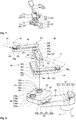
- the loading/unloading robot 10 includes a support unit 20 installed so as to be capable of being raised and lowered, an arm unit 40 (41, 51) attached to the support unit, and a hand unit 60 attached to the arm unit 40.
- the support unit 20 includes a pillar portion 21 installed so as to be capable of being raised and lowered, a base portion 22 fixed to the pillar portion 21, and a head portion 23 attached to the base portion 22.
- the pillar portion 21 is capable of being raised and lowered in the vertical direction and is also capable of rotating (revolving) around a vertical axis a1 of the pillar portion 21.
- the base portion 22 that is integrally fixed to the pillar portion 21 is also raised or lowered and rotates (revolves).
- the base portion 22 extends horizontally from a rear portion fixed to the pillar portion 21 and at a front portion of the base portion 22, the head portion 23 is supported so as to be rotatable around a second rotational axis a2 (see FIG. 2 ).
- a revolution axis portion including the revolution axis a1 is disposed at the rear portion of the base portion 22 and a second rotational axis portion including the second rotational axis a2 is disposed at the front portion of the base portion 22.
- the center distance (i.e., radius of revolution of the base portion) L1 (see FIG. 3B ) from the vertical axis (revolution axis) a1 of the base portion 22 to the second rotational axis a2 matches an intersection separation distance L5 (see FIG. 4A ) described later.
- the head portion 23 is attached to the base portion 22 so as to be rotatable around the second rotational axis a2.
- rear portions 42a, 52a of left and right arms 41, 51, described later, that construct an arm unit 40 are attached to the head portion 23 so as to be rotatable around axes of rotation a3.
- the head portion 23 has a second rotational axis portion with the second rotational axis a2 disposed at the rear portion of the head portion 23 and a third rotational axis portion with the third axes of rotation a3 disposed at a front portion of the head portion 23.
- the center distance (i.e., rotational radius of the head portion) L2 from the second rotational axis a2 of the head portion 23 to the third rotation axes a3 that are the axes where the arms are supported is shorter than the center distance L1 from the vertical axis a1 of the base portion 22 to the second rotational axis a2.
- the arm unit 40 includes multi-jointed arms 41, 51 that form a left-right pair.
- the right arm (one arm) 41 disposed on the right side (one side) includes a first right arm (rear arm) 42 that is rotatably attached to the head portion 23 and a second right arm (front arm) 43 that is rotatably attached to the first arm 42.
- the first arm 42 is rotatably attached to the third rotational axis portion of the head portion 23 that is provided with the right-side third rotational axis a3.
- a rear portion of the second arm 43 is rotatably attached to the front portion of the first arm 42.
- Operation of the right arm 41 is controlled by a controller (not shown) described later so that a front end portion 43a of the second arm 43 positioned at the front end of the right arm 41 moves in a straight line.
- a hand supporting axis a4 at the front end portion 43a of the right arm 41 is moved forward and backward (linear movement) along a straight line m1 in a forward/backward direction GB that passes above the head portion 23.
- the left arm (other arm) 51 disposed on the left side that is the other side includes a first left arm 52 that is rotatably attached to the head portion 23 and a second left arm 53 that is rotatably attached to the first arm 52.
- the first arm 52 is rotatably attached to a third rotational axis portion provided with the left-side third rotational axis a3, and movement of a front end portion 53a of the left arm 51 is controlled by a controller so as to move forward and backward along a straight line m2 in the forward/backward direction GB that passes the head portion 23.
- the construction and operation of the left arm 51 exhibit left/right symmetry with the right arm 41.
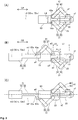
- center distance L3 (see FIG. 3A ) between the rotational axes a3, a3 of both arms 41, 51 is shorter than the center distance L1 (see FIG. 3B ) from the vertical axis a1 of the head portion 23 to the second rotational axis a2.
- the center distance L4 in the forward/backward direction from the second rotational axis a2 of the head portion 23 to each third rotational axis a3 of the respective arms is shorter than the center distance L3 between the third rotational axes a3, a3 of both arms.
- the forward/backward direction GB is a direction that is set using the head portion 23 as a reference and in the present embodiment is the horizontal direction which is perpendicular to a straight line that joins both axes of rotation a3 of the head portion 23.
- the front end portions 43a, 53a of the respective arms 41, 51 described above always move forward and backward with respect to the head portion 23 on predetermined straight lines m1, m2.
- the arms 41, 51 that carry out simple operations in this way are easy to control and can be controlled with superior stability.
- the hand unit 60 includes an upper hand (loading/unloading hand) 61 attached to the right arm 41 and a lower hand 71 attached to the left arm 51.
- the upper hand 61 is equipped with an upper rod portion 62 attached to the second arm 43 of the right arm 41 and an upper hand portion 63 attached to a front end of the upper rod portion 62.
- the upper rod portion 62 is rotatably attached to the front end portion 43a of the second arm 43 and is controlled by a driving mechanism 80 (see FIG. 2 ) and a controller (not shown) so that the orientation of the length direction of the upper rod portion 62 is always in the forward/backward direction GB. Accordingly, the upper hand 61 moves in the forward/backward direction GB in a state where the length direction of the upper rod portion 62 is always oriented in the forward/backward direction GB.
- the upper rod portion 62 is also provided with an offset portion 62a at a base-end part of the upper rod portion 62, and moves forward and backward along a straight line m3 in the forward/backward direction GB so as to pass directly above the second rotational axis a2 of the head portion 23.
- the lower hand 71 is constructed with left/right symmetry with respect to the upper hand 61 (see FIG. 3C ).
- corresponding members have been assigned corresponding reference numerals (as examples, the first arm of the left arm 51 that corresponds to the first arm 42 of the right arm 41 has been assigned the reference numeral "52", the rear portion of the first arm 52 on the left that corresponds to the rear portion 42a of the first arm 42 on the right has been assigned the reference numeral "52a", and the lower hand that corresponds to the upper hand 61 has been assigned the reference numeral "71") and description of such corresponding members is omitted here.
- a forward/backward movement line 72m (see FIG. 5A ) that matches a forward/backward movement path where a lower rod portion 72 moves along the straight line m3 is positioned directly below a forward/backward movement line 62m that matches a forward/backward movement path where the upper rod portion 62 moves along the straight line m3 and the forward/backward movement lines 62m, 72m are parallel.
- the loading/unloading robot 10 is also equipped with the driving mechanism 80, which realizes movement such as raising and lowering of the pillar portion 21 of the support unit 20, revolution of the base portion 22, rotation of the head portion 23, and forward and backward movement of the arm unit 40 and the hand unit 60, and a controller (not shown) for controlling the driving mechanism 80.
- the driving mechanism 80 which realizes movement such as raising and lowering of the pillar portion 21 of the support unit 20, revolution of the base portion 22, rotation of the head portion 23, and forward and backward movement of the arm unit 40 and the hand unit 60, and a controller (not shown) for controlling the driving mechanism 80.
- the driving mechanism 80 is equipped with a base revolving mechanism 81 that revolves the base portion 22, a head rotating mechanism 82 that revolves the head portion 23, a right extending/retracting mechanism 83 that bends and extends the right arm 41 to cause the upper hand 61 to move forward and backward, and a left extending/retracting mechanism 84 that bends and extends the left arm 51 to cause the lower hand 71 to move forward and backward.
- the base revolving mechanism 81 is equipped with a revolution reducer 81a that is interposed in a revolution axis portion that supports the base portion 22 so as to be capable of revolution with respect to the pillar portion 21, a revolution motor 81b that is incorporated in the base portion 22, and a belt 81d that transmits a rotational force of the revolution motor 81b to a driving side pulley 81c of the revolution reducer 81a. Since the driven side of the revolution reducer 81a is fixed to the pillar portion 21, when the revolution motor 81b inside the base portion 22 is operated, the base portion 22 revolves.
- the head rotating mechanism 82 is equipped with a rotation reducer 82a that is interposed in a rotational axis portion that supports the head portion 23 so as to be able to revolve with respect to the base portion 22, a rotation motor 82b that is incorporated in the base portion 22, and a belt 82d that transmits a rotational force of the rotation motor 82b to a driving side pulley 82c of the rotation reducer 82a. Since the driven side of the rotation reducer 82a is fixed to the head portion, when the rotation motor 82b in the base portion 22 is operated, the head portion 23 revolves.
- the right extending/retracting mechanism 83 is equipped with a rotation reducer 83a that is interposed in a third rotational axis portion that supports the first arm 42 of the right arm 41 so as to be rotatable with respect to the head portion 23, a rotation motor 83b that is incorporated in the head portion 23, a belt 83d that transmits a rotational force of the rotation motor 83b to a driving side pulley 83c of the rotation reducer 83a, and an extending/bending power transmitting portion 85 that causes the right arm 41 to extend and bend together when a driven-side rotational shaft 83e of the rotation reducer 83a rotates.
- the extending/bending power transmitting portion 85 includes a first rotational shaft 85a that supports the rear portion of the first arm 42 so as to be rotatable with respect to the head portion 23, a second rotational shaft 85b that supports the second arm 43 so as to be rotatable with respect to the first arm 42, and a third rotational shaft 85c that supports the upper hand 61 so as to be rotatable with respect to the second arm 43.
- the first rotational shaft 85a is integrally connected to the driven-side rotational shaft 83e of the rotation reducer 83a and a driving pulley 85d is installed inside the first arm 42 at an end portion thereof.
- Intermediate pulleys 85e, 85f are attached to both ends of the second rotational shaft 85b that are respectively positioned inside the first arm 42 and the second arm 43.
- a driven pulley 85g is attached to an end portion of the third rotational shaft 85c positioned inside the second arm 43, and an upper hand 61-side end portion of the third rotational shaft 85c is rotatably connected to the upper hand 61.
- the driving pulley 85d and the intermediate pulley 85e are therefore caused to move together by a belt 85h and the intermediate pulley 85f and the driven pulley 85g are caused move together by a belt 85i.
- the rotation motor 83b when the rotation motor 83b is operated, the rotation of the motor is transmitted via the rotation reducer 83a to the first rotational shaft 85a of the extending/bending power transmitting portion 85, the right arm 41 bends or extends, and the upper hand 61 moves forward or backward.
- the diameters of the pulleys 85d to 85g of the extending/bending power transmitting portion 85 are set so that the third rotational shaft 85c at the front end (the rear portion of the upper hand 61) of the second arm 43 moves in a straight line in the forward/backward direction GB when the right arm 41 bends or extends. Accordingly, by operating the rotating motor 83b, it is possible to move the upper hand 61 forward and backward in the forward/backward direction GB.
- the construction and operation of the left extending/retracting mechanism 84 for moving the lower hand 71 forward and backward when the left arm 51 bends and extends exhibit left/right symmetry with the right extending/retracting mechanism 83.
- corresponding members have been assigned corresponding reference numerals (as examples, the left rotation reducer that corresponds to the right rotation reducer 83a has been assigned the reference numeral "84a" and the first rotational shaft of an extending/bending power transmitting portion 86 on the left that corresponds to the first rotational shaft 85a of the extending/bending power transmitting portion 85 on the right has been assigned the reference numeral "86a") and description of such corresponding members is omitted here.
- the controller carries out control that realizes the operations described later in this specification, which for example includes posture control to place the loading/unloading robot 10 into a predetermined posture, panel receiving operation control, panel interchanging operation control, and panel unloading operation control. Note that the driving mechanism and the controller are well-known and detailed description thereof is omitted here.
- the loading/unloading robot 10 is used in a panel processing apparatus that processes a panel material P (hereinafter, simply "panel P") that is to be conveyed.
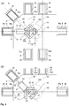
- a panel supplying unit 90 equipped with a supply port 90p for panels, panel processing units 91 to 95 equipped with panel loading/unloading ports 91p to 95p, and an unloading port 96p that is the unloading destination of panels P that have been processed are installed at positions adjacent to the loading/unloading robot 10 so that the loading/unloading robot 10 is surrounded by the respective ports (i.e., the destinations for loading and unloading panels).
- the loading/unloading robot 10 is disposed inside a chamber or an EFEM (Equipment Front End Module) and the respective ports are connected to such chamber or EFEM.
- Panel processing apparatuses that have such ports and the loading/unloading robot 10 construct a panel loading/unloading system S where favorable operation is possible at the panel processing apparatuses.
- a rack R on which a panel P to be loaded or unloaded is placed is installed in each of the panel supplying unit 90, the panel processing units 91 to 95, and the panel unloading unit 96.
- the racks R installed in the present embodiment are single-story racks, it is also possible to use multistory racks where a plurality of panels P can be placed in the up-down direction. It is also possible to use wire trays or semiconductor wafer containers as the racks R.
- the panels P are loaded into and unloaded from the respective ports 90p to 96p via openings (not shown) that face the loading/unloading robot side. Via the ports 90p to 96p, it is possible to linearly load and unload the panels P into and from the racks R installed in the panel supplying unit 90 and the like.
- FIG. 4A shows linear loading/unloading lines S1 to S4 that pass through the centers of the respective ports 90p to 96p.
- the ports 90p to 96p are all disposed so that the loading/unloading lines S1 to S4 all pass inside a range of a line of revolution 22S of the second rotational axis a2 of the base portion 22.
- a port layout is used where there is at least one intersection where the loading/unloading lines of the respective ports intersect one another.
- first intersection X1 where the loading/unloading line S1 of the supply port 90p (unloading port 96p), the loading/unloading line S2 of the first panel loading/unloading port 91p, and the loading/unloading line S3 of the second panel loading/unloading port 92p (the fifth panel loading/unloading port 95p) intersect.
- second intersection X2 where the loading/unloading line S4 of the third panel loading/unloading port 93p (the fourth panel loading/unloading port 94p) and the loading/unloading line S1 of the unloading port 96p intersect.
- intersections X1, X2 are both positioned inside the range of the line of revolution 22S mentioned above.
- the respective intersections X1, X2 are positioned in the range of revolution so as to be positioned on the line of revolution 22S (arc of revolution).
- the intersection separation distance L5 from the raising/lowering axis a1 of the base portion 22 to the respective intersections X1, X2 matches the center distance (the radius of revolution of the base portion) L1 (see FIG. 3B ) from the vertical axis (axis of revolution) a1 of the base portion 22 to the second rotational axis a2.
- the operation of the loading/unloading robot 10 will be described for a case where a panel P that has been received at the panel supplying unit 90 (see FIG. 4A ) is processed by the first panel processing unit 91.
- the operation of the loading/unloading robot 10 will be explained with a state where a panel P being processed is present in the first panel processing unit 91 and panels have not been loaded on the upper hand 61 or the lower hand 71 of the loading/unloading robot 10 as a starting point.
- the posture of the loading/unloading robot 10 is placed in a posture where it is capable of receiving a panel from the panel supplying unit 90 (posture control). More specifically, first the base portion 22 is revolved and the second rotational axis a2 at the front end of the base portion 22 is positioned on the loading/unloading line S1 of the supply port 90p (see FIG. 4A ). The base portion 22 also aligns the forward/backward movement lines m3 (see FIGS. 3A to 3C ) of both rod portions 62, 72 with the loading/unloading line S1 of the supply port 90p (see FIG. 4A ). That is, posture control is carried out to produce a state where the base portion 22 and the head portion 23 face the panel supplying unit 90.
- the pillar portion 21 is raised or lowered so that the height of a hand (here, the lower hand 71) that has advanced toward the supply port 90p is at a position in the height direction where it is possible for the hand to advance below the rack R that holds the panel P inside the panel supplying unit 90.
- a hand here, the lower hand 71
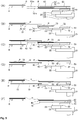
- the lower hand 71 is moved forward inside the panel supplying unit 90 and a lower hand portion 73 is positioned below the panel P to be processed inside the panel supplying unit 90 (see the dot-dot-dash line in FIG. 4A ).
- the pillar portion 21 is raised to raise the lower hand portion 73 and after the lower hand portion 73 has received the panel P, the lower hand portion 73 is moved backward (control of panel receiving operation). By doing so, reception of the panel P is completed and a state where it is possible to revolve the loading/unloading robot 10 or to rotate the hand unit is achieved.
- the posture of the loading/unloading robot 10 is placed in a posture where it is possible to interchange the panels P at the first panel processing unit 91. More specifically, the head portion 23 is rotated (swung) to the right by 45° so that the forward/backward movement lines m3 (see FIGS. 3A to 3C ) of both rod portions 62, 72 are aligned with the loading/unloading line S2 of the first panel loading/unloading port 91p (see FIG. 4B ).
- the pillar portion 21 is raised or lowered so that the height of the upper hand 61 (i.e., the hand that is to advance toward the first panel processing unit 91 first) is placed at a position in the height direction where the upper hand 61 is capable of advancing below a rack R that holds a processed panel P inside the first panel processing unit 91 (see FIG. 5A ). Once this state is reached, it is possible for the upper hand 61 to linearly move in the forward/backward direction GB and load into and unload from the first panel loading/unloading port 91p.
- the upper hand 61 is moved forward inside the first panel loading/unloading port 91p and an upper hand portion 63 is positioned below the processed panel P (see FIG. 5B ).
- the pillar portion 21 is raised to raise the upper hand portion 63 so that the processed panel P is received by the upper hand portion 63 (see FIG. 5C ).
- the height of the lower hand portion 73 (the height of the forward/backward movement line 72m) holding the panel P to be processed is set at a height where the lower hand portion 73 is capable of advancing above the rack R inside the first panel processing unit 91.
- the lower hand 71 is moved forward inside the first panel loading/unloading port 91p and the lower hand portion 73 is positioned above the rack R (see FIG. 5D ).
- the pillar portion 21 is then lowered to lower the lower hand portion 73 and the panel P to be processed (i.e., the unprocessed panel P) placed on the lower hand portion 73 is placed on the rack R inside the first panel processing unit 91 (see FIG. 5E ).
- the lower hand 71 is moved backward (control of panel interchanging operation). By doing so, the interchanging operation of panels is completed (see FIG. 5F ), and it becomes possible to revolve the loading/unloading robot 10 and to rotate the hand unit 60.
- the head portion 23 may be rotated further to the right by 45° (making a total of 90°) or the base portion 22 may be revolved to the right by 45° with the head portion 23 as it is and then the lower hand 71 and the upper hand 61 may be moved forward and backward.
- the base portion 22 that is a means for positioning the second rotational axis a2 of the head portion 23 that is directly supported on the base portion 22 differs completely in object, function, and movement to the respective joints that construct a multi-jointed arm.
- the respective joints of a multi-jointed arm normally make complex movements to position the front end of the multi-jointed arm at a desired position.
- the revolution operation described above is unnecessary secondly because the supply port 90p of the panel supplying unit 90 (see FIG. 4A ) and the first panel loading/unloading port 91p of the first panel processing unit 91 are disposed so that the loading/unloading line S1 of the supply port 90p and the loading/unloading line S2 of the first panel loading/unloading port 91p intersect, and additionally the supply port 90p and the first panel loading/unloading port 91p are disposed so that such intersection X1 is positioned on the arc of revolution 22S.
- the intersection separation distance L5 from the raising/lowering axis a1 of the base portion 22 to the respective intersections X1, X2 matches the center distance from the vertical axis a1 of the base portion 22 to the second rotational axis a2 (see FIG. 3B ).
- this construction makes it possible to position the second rotational axis a2 of the base portion 22 on a plurality of loading/unloading lines in a single operation by merely positioning the second rotational axis a2 of the base portion 22 at a predetermined intersection.
- the revolution operation described above is unnecessary because the base portion 22 is constructed so as to be rotatable around the second rotational axis a2 and, in a state where the second rotational axis a2 has been positioned on a loading/unloading line (for example, S1), is also a means for deciding the orientation of the forward/backward movement lines m3 of the hands 61, 71 so that the forward/backward movement lines m3 of the hands 61, 71 are positioned on a desired loading/unloading line (for example, S2).
- a loading/unloading line for example, S1
- the left and right arms 41, 51 are constructed so as to move with respect to the head portion 23 only in the predetermined forward/backward direction GB. Accordingly, operation control of the left and right arms is simple and it is possible to easily realize a stabilized forward/backward movement operation.
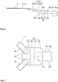
- a loading/unloading robot 11 includes the support unit 20 installed so as to be capable of being raised and lowered, the arm unit 40 that is attached to the support unit 20, and the hand unit 60 that is attached to the arm unit 40, but differs to the loading/unloading robot 10 according to the first embodiment in the construction of the head portion (see FIG. 6 ). Since the remaining construction is the same as the loading/unloading robot 10 according to the first embodiment, detailed description of the head portion is omitted here. Constructions that are the same have been assigned the same reference numerals and description thereof is omitted.
- a head portion 33 of the loading/unloading robot 11 includes a base-end portion 34 rotatably supported on the base portion 22, a front portion 35 that rotatably supports the first arms 42, 52 of the arm unit 40, and a stepped portion 36 that integrally joins the base-end portion 34 and the front portion 35.
- the base-end portion 34 of the head portion 33 is supported on the base portion 22 in a state so as to be rotatable around the second rotational axis a2.
- a head portion installation surface 22a of the base portion 22 that supports the head portion 33 is provided on the upper surface of a front portion of the base portion 22.
- base-end portions 42a,52a of the first arms 42, 52 of the left and right arms 41, 51 are attached so as to be rotatable around the axes of rotation a3.
- An arm installation surface 35a that supports base-end portions of the left and right arms 42, 52 is provided on the upper surface of the front portion 35 of the head portion 33.
- the height of the arm installation surface 35a of the head portion 33 may be flush with or higher than the height of the upper surface of the base portion 22, the arm installation surface 35a should preferably be lower than the upper surface of the base portion 22.
- the upper surface (arm installation surface) 35a of the front portion 35 of the head portion 33 is positioned lower than the upper surface (head portion installation surface) of the head base-end portion 34 and the height of a lower surface 35b of the head front portion 35 is positioned lower than the head portion installation surface 22a.
- the position in the height direction of the first arms 42, 52 of the arm unit 40 is set low and the positions in the height direction of the hands 61, 71 attached to the front ends of the left and right arms 41, 51 can be set lower.
- the loading/unloading robot 11 is disposed inside a vacuum chamber or an EFEM (Equipment Front End Module) for example, it is possible to reduce the volume of the chamber or the EFEM, which makes it possible to reduce the processing time at the start of the process and to shorten the restoration time during maintenance and the like.
- EFEM Equipment Front End Module
- the head portion 33 includes a rotation restricting member 37 that restricts the range of rotation of the head portion 33. Accordingly, if the head portion 33 rotates in the clockwise direction r, for example, the rotation restricting member 37 on the right side (the upper side in FIG. 7 ) of the head portion 23 strikes a side surface 22b of the base portion 22, thereby restricting rotation of the head portion 33.
- the rotatable range of the head portion 33 in the present embodiment is set at a range of around ⁇ 90° (in reality, 87°) based on a line that joins the raising/lowering axis a1 of the base portion 22 and the second rotational axis a2.
- the range of rotation of the head portion 33 can be arbitrarily set in a range of 0° to 90° according to the shape of the rotation restricting member 37 and/or the shape of the side surface 22b of the base portion 22.
- loading/unloading robot according to the present invention is not limited to the robots in the above embodiments.
- the present invention further includes loading/unloading robots that have been modified without departing from the scope of the present invention as defined in the patent claims.
- the hand unit 60 is moved back and forth by the multi-jointed arms 41, 51 that are freely capable of bending and extending, it is also possible to move the hand unit 60 using a slide mechanism realized using a slider or the like.
- intersection separation distance L5 (see FIG. 4A ) matches the center distance L1 (see FIG. 3B ) from the vertical axis a1 of the base portion 22 to the second rotational axis a2 in the first embodiment, the intersection separation distance L5 may be shorter than the center distance L1.
- revolution motor 81b of the base revolving mechanism 81 of the driving mechanism 80 is installed in the base portion 22 in the first embodiment described above, the revolution motor 81b may be installed in the pillar portion 21, and although the rotation motor 82b of the head rotating mechanism 82 is installed in the base portion 22, the rotation motor 82b may be installed in the head portion 23.
- rotation restricting member 37 of the head portion 33 is provided on the head portion 33 side in the loading/unloading robot 11 according to the second embodiment described above, a rotation restricting member may be provided on the base portion 22 side or rotation restricting members may be provided on both the base portion 22 and the head portion 23.
- the rotatable range of the head portion 33 may be a range of ⁇ 45° with respect to a segment that joins the raising/lowering axis a1 and the second rotational axis a2 of the base portion 22.
Landscapes
- Engineering & Computer Science (AREA)
- Robotics (AREA)
- Mechanical Engineering (AREA)
- Manipulator (AREA)
- Container, Conveyance, Adherence, Positioning, Of Wafer (AREA)
Applications Claiming Priority (2)
| Application Number | Priority Date | Filing Date | Title |
|---|---|---|---|
| JP2012222551A JP5990359B2 (ja) | 2012-10-04 | 2012-10-04 | 搬入出ロボット |
| EP13187347.3A EP2716416B1 (en) | 2012-10-04 | 2013-10-04 | Loading/unloading robot |
Related Parent Applications (2)
| Application Number | Title | Priority Date | Filing Date |
|---|---|---|---|
| EP13187347.3A Division EP2716416B1 (en) | 2012-10-04 | 2013-10-04 | Loading/unloading robot |
| EP13187347.3A Division-Into EP2716416B1 (en) | 2012-10-04 | 2013-10-04 | Loading/unloading robot |
Publications (3)
| Publication Number | Publication Date |
|---|---|
| EP3056321A2 EP3056321A2 (en) | 2016-08-17 |
| EP3056321A3 EP3056321A3 (en) | 2017-03-01 |
| EP3056321B1 true EP3056321B1 (en) | 2019-07-03 |
Family
ID=49354445
Family Applications (2)
| Application Number | Title | Priority Date | Filing Date |
|---|---|---|---|
| EP16162163.6A Active EP3056321B1 (en) | 2012-10-04 | 2013-10-04 | Loading/unloading robot |
| EP13187347.3A Active EP2716416B1 (en) | 2012-10-04 | 2013-10-04 | Loading/unloading robot |
Family Applications After (1)
| Application Number | Title | Priority Date | Filing Date |
|---|---|---|---|
| EP13187347.3A Active EP2716416B1 (en) | 2012-10-04 | 2013-10-04 | Loading/unloading robot |
Country Status (6)
| Country | Link |
|---|---|
| US (1) | US9174346B2 (cg-RX-API-DMAC7.html) |
| EP (2) | EP3056321B1 (cg-RX-API-DMAC7.html) |
| JP (1) | JP5990359B2 (cg-RX-API-DMAC7.html) |
| KR (1) | KR101580718B1 (cg-RX-API-DMAC7.html) |
| CN (1) | CN103707285B (cg-RX-API-DMAC7.html) |
| TW (1) | TWI529045B (cg-RX-API-DMAC7.html) |
Families Citing this family (20)
| Publication number | Priority date | Publication date | Assignee | Title |
|---|---|---|---|---|
| JP6411852B2 (ja) | 2014-10-07 | 2018-10-24 | 平田機工株式会社 | 搬送装置、搬送システム及び搬送方法 |
| WO2016056119A1 (ja) * | 2014-10-10 | 2016-04-14 | 川崎重工業株式会社 | 基板搬送ロボットおよびその運転方法 |
| WO2016172003A1 (en) * | 2015-04-20 | 2016-10-27 | Applied Materials, Inc. | Buffer chamber wafer heating mechanism and supporting robot |
| JP6487267B2 (ja) * | 2015-04-27 | 2019-03-20 | 日本電産サンキョー株式会社 | 製造システム |
| JP6487266B2 (ja) | 2015-04-27 | 2019-03-20 | 日本電産サンキョー株式会社 | 製造システム |
| JP6594177B2 (ja) * | 2015-11-24 | 2019-10-23 | 平田機工株式会社 | ハンド部材およびハンド |
| CN107378982A (zh) * | 2017-09-12 | 2017-11-24 | 李从宾 | 一种智能机器人抓取装置 |
| TWI758595B (zh) * | 2018-03-31 | 2022-03-21 | 日商平田機工股份有限公司 | 腔室構造 |
| JP7183635B2 (ja) | 2018-08-31 | 2022-12-06 | 東京エレクトロン株式会社 | 基板搬送機構、基板処理装置及び基板搬送方法 |
| JP7225613B2 (ja) * | 2018-09-03 | 2023-02-21 | 東京エレクトロン株式会社 | 基板搬送機構、基板処理装置及び基板搬送方法 |
| JP7409800B2 (ja) * | 2019-08-09 | 2024-01-09 | 川崎重工業株式会社 | ロボット制御装置、ロボット、及びロボット制御方法 |
| TWI703079B (zh) * | 2019-11-21 | 2020-09-01 | 辛耘企業股份有限公司 | 輸送裝置 |
| KR102272535B1 (ko) * | 2020-12-14 | 2021-07-05 | (주)볼타오토메이션 | 반송로봇용 듀얼타입의 반송암모듈 |
| KR102348261B1 (ko) * | 2021-05-31 | 2022-01-10 | (주) 티로보틱스 | 진공 챔버에서 기판을 이송하기 위한 기판 이송 로봇 |
| KR102307687B1 (ko) * | 2021-06-25 | 2021-10-05 | (주) 티로보틱스 | 기판 이송 로봇을 진공 챔버 내에서 주행하기 위한 주행 로봇 |
| KR102307690B1 (ko) * | 2021-06-25 | 2021-10-05 | (주) 티로보틱스 | 진공 챔버에서 기판을 이송하기 위한 기판 이송 로봇 |
| KR102396650B1 (ko) * | 2021-07-21 | 2022-05-12 | 주식회사 싸이맥스 | 3절 링크 대기형 로봇 |
| CN114043464B (zh) * | 2021-11-26 | 2023-11-03 | 四川建安工业有限责任公司 | 可伸缩式机械手 |
| WO2023188181A1 (ja) * | 2022-03-30 | 2023-10-05 | 平田機工株式会社 | 基板搬送システム及び移載ロボット |
| WO2023188177A1 (ja) * | 2022-03-30 | 2023-10-05 | 平田機工株式会社 | 基板搬送システム及び移載ロボット制御装置 |
Family Cites Families (20)
| Publication number | Priority date | Publication date | Assignee | Title |
|---|---|---|---|---|
| US4585387A (en) * | 1983-10-11 | 1986-04-29 | William Jayne | Robot arm |
| JPH03154736A (ja) * | 1989-11-10 | 1991-07-02 | Hitachi Ltd | 移動体のストツパ機構 |
| JPH0549293U (ja) * | 1991-11-29 | 1993-06-29 | ぺんてる株式会社 | ロボットア−ムのストッパ装置 |
| JPH0650778U (ja) * | 1992-12-24 | 1994-07-12 | 株式会社ダイフク | アーム回動式作業装置 |
| JPH08172121A (ja) * | 1994-12-20 | 1996-07-02 | Hitachi Ltd | 基板搬送装置 |
| US5993142A (en) * | 1997-07-10 | 1999-11-30 | Genmark Automation, Inc. | Robot having multiple degrees of freedom in an isolated environment |
| JPH11188671A (ja) * | 1997-12-26 | 1999-07-13 | Daihen Corp | 2アーム方式の搬送用ロボット装置 |
| JPH11300659A (ja) * | 1998-04-24 | 1999-11-02 | Mecs Corp | 薄型基板搬送多関節ロボット |
| JP2000000786A (ja) * | 1998-06-16 | 2000-01-07 | Komatsu Ltd | 同期制御装置 |
| JP2000077499A (ja) | 1998-09-03 | 2000-03-14 | Dainippon Screen Mfg Co Ltd | 基板処理装置 |
| US6297611B1 (en) * | 2000-07-06 | 2001-10-02 | Genmark Automation | Robot having independent end effector linkage motion |
| TW550651B (en) * | 2001-08-08 | 2003-09-01 | Tokyo Electron Ltd | Substrate conveying apparatus, substrate processing system, and substrate conveying method |
| JP4411025B2 (ja) * | 2003-07-11 | 2010-02-10 | 株式会社ダイヘン | 2アーム式搬送ロボット |
| JP4959427B2 (ja) * | 2007-06-05 | 2012-06-20 | 日本電産サンキョー株式会社 | 産業用ロボット |
| JP5059729B2 (ja) * | 2008-09-30 | 2012-10-31 | 株式会社日立ハイテクコントロールシステムズ | ウェーハ搬送ロボット及びウェーハ搬送装置 |
| US8757345B2 (en) * | 2009-04-29 | 2014-06-24 | Novellus Systems, Inc. | Magnetic rotational hardstop for robot |
| JP2011119556A (ja) * | 2009-12-07 | 2011-06-16 | Yaskawa Electric Corp | 水平多関節ロボットおよびそれを備えた搬送装置 |
| JP5071514B2 (ja) * | 2010-04-21 | 2012-11-14 | 株式会社安川電機 | 水平多関節ロボットおよびそれを備えた基板搬送システム |
| JP5578973B2 (ja) * | 2010-07-16 | 2014-08-27 | 日本電産サンキョー株式会社 | 産業用ロボット |
| JP5565345B2 (ja) * | 2011-03-07 | 2014-08-06 | 株式会社安川電機 | 搬送ロボット |
-
2012
- 2012-10-04 JP JP2012222551A patent/JP5990359B2/ja active Active
-
2013
- 2013-09-29 CN CN201310455928.4A patent/CN103707285B/zh active Active
- 2013-10-03 TW TW102135815A patent/TWI529045B/zh active
- 2013-10-04 EP EP16162163.6A patent/EP3056321B1/en active Active
- 2013-10-04 US US14/046,485 patent/US9174346B2/en active Active
- 2013-10-04 KR KR1020130118383A patent/KR101580718B1/ko active Active
- 2013-10-04 EP EP13187347.3A patent/EP2716416B1/en active Active
Non-Patent Citations (1)
| Title |
|---|
| None * |
Also Published As
| Publication number | Publication date |
|---|---|
| CN103707285A (zh) | 2014-04-09 |
| US9174346B2 (en) | 2015-11-03 |
| TWI529045B (zh) | 2016-04-11 |
| US20140099180A1 (en) | 2014-04-10 |
| EP3056321A3 (en) | 2017-03-01 |
| EP3056321A2 (en) | 2016-08-17 |
| KR101580718B1 (ko) | 2015-12-28 |
| JP5990359B2 (ja) | 2016-09-14 |
| EP2716416A2 (en) | 2014-04-09 |
| EP2716416A3 (en) | 2014-11-12 |
| JP2014073558A (ja) | 2014-04-24 |
| CN103707285B (zh) | 2016-06-29 |
| TW201424961A (zh) | 2014-07-01 |
| EP2716416B1 (en) | 2016-04-27 |
| KR20140044278A (ko) | 2014-04-14 |
Similar Documents
| Publication | Publication Date | Title |
|---|---|---|
| EP3056321B1 (en) | Loading/unloading robot | |
| JP6766227B2 (ja) | 双腕ロボット | |
| JP4411025B2 (ja) | 2アーム式搬送ロボット | |
| KR101429827B1 (ko) | 반송 시스템 | |
| KR101820037B1 (ko) | 기판 반송 장치 | |
| US8136422B2 (en) | Articulated robot | |
| JP2002158272A (ja) | ダブルアーム基板搬送装置 | |
| JP2008272864A (ja) | 産業用ロボット及び集合処理装置 | |
| JP2005039047A (ja) | 多関節ロボット | |
| KR20110039455A (ko) | 판상 워크의 이송 설비 및 이송 방법 | |
| JP2009028847A (ja) | 搬送装置 | |
| TWI488791B (zh) | 搬運器裝置 | |
| TW200414297A (en) | Apparatus for vacuum treating two dimensionally extended substrates and method for manufacturing such substrates | |
| TW201617192A (zh) | 機器人及機器人系統 | |
| JP5263945B2 (ja) | ダブルアーム型ロボット | |
| JP2004288720A (ja) | 基板搬送装置及び基板処理装置 | |
| CN107534008A (zh) | 晶片交换器 | |
| US20130209201A1 (en) | Carrier device | |
| JP2005150575A (ja) | ダブルアーム型ロボット | |
| JP2011025358A (ja) | 生産システム | |
| CN116157239A (zh) | 运送装置以及机器人系统 | |
| KR102758778B1 (ko) | 반송 로봇 및 이것을 구비한 작업물 반송 시스템 | |
| KR100760200B1 (ko) | 반송로봇 |
Legal Events
| Date | Code | Title | Description |
|---|---|---|---|
| PUAI | Public reference made under article 153(3) epc to a published international application that has entered the european phase |
Free format text: ORIGINAL CODE: 0009012 |
|
| AC | Divisional application: reference to earlier application |
Ref document number: 2716416 Country of ref document: EP Kind code of ref document: P |
|
| AK | Designated contracting states |
Kind code of ref document: A2 Designated state(s): AL AT BE BG CH CY CZ DE DK EE ES FI FR GB GR HR HU IE IS IT LI LT LU LV MC MK MT NL NO PL PT RO RS SE SI SK SM TR |
|
| PUAL | Search report despatched |
Free format text: ORIGINAL CODE: 0009013 |
|
| AK | Designated contracting states |
Kind code of ref document: A3 Designated state(s): AL AT BE BG CH CY CZ DE DK EE ES FI FR GB GR HR HU IE IS IT LI LT LU LV MC MK MT NL NO PL PT RO RS SE SI SK SM TR |
|
| RIC1 | Information provided on ipc code assigned before grant |
Ipc: B25J 9/04 20060101AFI20170126BHEP |
|
| STAA | Information on the status of an ep patent application or granted ep patent |
Free format text: STATUS: REQUEST FOR EXAMINATION WAS MADE |
|
| 17P | Request for examination filed |
Effective date: 20170829 |
|
| RBV | Designated contracting states (corrected) |
Designated state(s): AL AT BE BG CH CY CZ DE DK EE ES FI FR GB GR HR HU IE IS IT LI LT LU LV MC MK MT NL NO PL PT RO RS SE SI SK SM TR |
|
| GRAP | Despatch of communication of intention to grant a patent |
Free format text: ORIGINAL CODE: EPIDOSNIGR1 |
|
| STAA | Information on the status of an ep patent application or granted ep patent |
Free format text: STATUS: GRANT OF PATENT IS INTENDED |
|
| INTG | Intention to grant announced |
Effective date: 20190128 |
|
| GRAS | Grant fee paid |
Free format text: ORIGINAL CODE: EPIDOSNIGR3 |
|
| GRAA | (expected) grant |
Free format text: ORIGINAL CODE: 0009210 |
|
| STAA | Information on the status of an ep patent application or granted ep patent |
Free format text: STATUS: THE PATENT HAS BEEN GRANTED |
|
| AC | Divisional application: reference to earlier application |
Ref document number: 2716416 Country of ref document: EP Kind code of ref document: P |
|
| AK | Designated contracting states |
Kind code of ref document: B1 Designated state(s): AL AT BE BG CH CY CZ DE DK EE ES FI FR GB GR HR HU IE IS IT LI LT LU LV MC MK MT NL NO PL PT RO RS SE SI SK SM TR |
|
| REG | Reference to a national code |
Ref country code: GB Ref legal event code: FG4D |
|
| REG | Reference to a national code |
Ref country code: CH Ref legal event code: EP Ref country code: AT Ref legal event code: REF Ref document number: 1150408 Country of ref document: AT Kind code of ref document: T Effective date: 20190715 |
|
| REG | Reference to a national code |
Ref country code: IE Ref legal event code: FG4D |
|
| REG | Reference to a national code |
Ref country code: CH Ref legal event code: NV Representative=s name: VALIPAT S.A. C/O BOVARD SA NEUCHATEL, CH |
|
| REG | Reference to a national code |
Ref country code: DE Ref legal event code: R096 Ref document number: 602013057543 Country of ref document: DE |
|
| REG | Reference to a national code |
Ref country code: NL Ref legal event code: FP |
|
| REG | Reference to a national code |
Ref country code: LT Ref legal event code: MG4D |
|
| REG | Reference to a national code |
Ref country code: AT Ref legal event code: MK05 Ref document number: 1150408 Country of ref document: AT Kind code of ref document: T Effective date: 20190703 |
|
| PG25 | Lapsed in a contracting state [announced via postgrant information from national office to epo] |
Ref country code: LT Free format text: LAPSE BECAUSE OF FAILURE TO SUBMIT A TRANSLATION OF THE DESCRIPTION OR TO PAY THE FEE WITHIN THE PRESCRIBED TIME-LIMIT Effective date: 20190703 Ref country code: FI Free format text: LAPSE BECAUSE OF FAILURE TO SUBMIT A TRANSLATION OF THE DESCRIPTION OR TO PAY THE FEE WITHIN THE PRESCRIBED TIME-LIMIT Effective date: 20190703 Ref country code: PT Free format text: LAPSE BECAUSE OF FAILURE TO SUBMIT A TRANSLATION OF THE DESCRIPTION OR TO PAY THE FEE WITHIN THE PRESCRIBED TIME-LIMIT Effective date: 20191104 Ref country code: SE Free format text: LAPSE BECAUSE OF FAILURE TO SUBMIT A TRANSLATION OF THE DESCRIPTION OR TO PAY THE FEE WITHIN THE PRESCRIBED TIME-LIMIT Effective date: 20190703 Ref country code: HR Free format text: LAPSE BECAUSE OF FAILURE TO SUBMIT A TRANSLATION OF THE DESCRIPTION OR TO PAY THE FEE WITHIN THE PRESCRIBED TIME-LIMIT Effective date: 20190703 Ref country code: CZ Free format text: LAPSE BECAUSE OF FAILURE TO SUBMIT A TRANSLATION OF THE DESCRIPTION OR TO PAY THE FEE WITHIN THE PRESCRIBED TIME-LIMIT Effective date: 20190703 Ref country code: BG Free format text: LAPSE BECAUSE OF FAILURE TO SUBMIT A TRANSLATION OF THE DESCRIPTION OR TO PAY THE FEE WITHIN THE PRESCRIBED TIME-LIMIT Effective date: 20191003 Ref country code: NO Free format text: LAPSE BECAUSE OF FAILURE TO SUBMIT A TRANSLATION OF THE DESCRIPTION OR TO PAY THE FEE WITHIN THE PRESCRIBED TIME-LIMIT Effective date: 20191003 Ref country code: AT Free format text: LAPSE BECAUSE OF FAILURE TO SUBMIT A TRANSLATION OF THE DESCRIPTION OR TO PAY THE FEE WITHIN THE PRESCRIBED TIME-LIMIT Effective date: 20190703 |
|
| PG25 | Lapsed in a contracting state [announced via postgrant information from national office to epo] |
Ref country code: IS Free format text: LAPSE BECAUSE OF FAILURE TO SUBMIT A TRANSLATION OF THE DESCRIPTION OR TO PAY THE FEE WITHIN THE PRESCRIBED TIME-LIMIT Effective date: 20191103 Ref country code: ES Free format text: LAPSE BECAUSE OF FAILURE TO SUBMIT A TRANSLATION OF THE DESCRIPTION OR TO PAY THE FEE WITHIN THE PRESCRIBED TIME-LIMIT Effective date: 20190703 Ref country code: AL Free format text: LAPSE BECAUSE OF FAILURE TO SUBMIT A TRANSLATION OF THE DESCRIPTION OR TO PAY THE FEE WITHIN THE PRESCRIBED TIME-LIMIT Effective date: 20190703 Ref country code: GR Free format text: LAPSE BECAUSE OF FAILURE TO SUBMIT A TRANSLATION OF THE DESCRIPTION OR TO PAY THE FEE WITHIN THE PRESCRIBED TIME-LIMIT Effective date: 20191004 Ref country code: LV Free format text: LAPSE BECAUSE OF FAILURE TO SUBMIT A TRANSLATION OF THE DESCRIPTION OR TO PAY THE FEE WITHIN THE PRESCRIBED TIME-LIMIT Effective date: 20190703 Ref country code: RS Free format text: LAPSE BECAUSE OF FAILURE TO SUBMIT A TRANSLATION OF THE DESCRIPTION OR TO PAY THE FEE WITHIN THE PRESCRIBED TIME-LIMIT Effective date: 20190703 |
|
| PG25 | Lapsed in a contracting state [announced via postgrant information from national office to epo] |
Ref country code: TR Free format text: LAPSE BECAUSE OF FAILURE TO SUBMIT A TRANSLATION OF THE DESCRIPTION OR TO PAY THE FEE WITHIN THE PRESCRIBED TIME-LIMIT Effective date: 20190703 |
|
| PG25 | Lapsed in a contracting state [announced via postgrant information from national office to epo] |
Ref country code: DK Free format text: LAPSE BECAUSE OF FAILURE TO SUBMIT A TRANSLATION OF THE DESCRIPTION OR TO PAY THE FEE WITHIN THE PRESCRIBED TIME-LIMIT Effective date: 20190703 Ref country code: EE Free format text: LAPSE BECAUSE OF FAILURE TO SUBMIT A TRANSLATION OF THE DESCRIPTION OR TO PAY THE FEE WITHIN THE PRESCRIBED TIME-LIMIT Effective date: 20190703 Ref country code: PL Free format text: LAPSE BECAUSE OF FAILURE TO SUBMIT A TRANSLATION OF THE DESCRIPTION OR TO PAY THE FEE WITHIN THE PRESCRIBED TIME-LIMIT Effective date: 20190703 Ref country code: RO Free format text: LAPSE BECAUSE OF FAILURE TO SUBMIT A TRANSLATION OF THE DESCRIPTION OR TO PAY THE FEE WITHIN THE PRESCRIBED TIME-LIMIT Effective date: 20190703 Ref country code: IT Free format text: LAPSE BECAUSE OF FAILURE TO SUBMIT A TRANSLATION OF THE DESCRIPTION OR TO PAY THE FEE WITHIN THE PRESCRIBED TIME-LIMIT Effective date: 20190703 |
|
| PG25 | Lapsed in a contracting state [announced via postgrant information from national office to epo] |
Ref country code: SM Free format text: LAPSE BECAUSE OF FAILURE TO SUBMIT A TRANSLATION OF THE DESCRIPTION OR TO PAY THE FEE WITHIN THE PRESCRIBED TIME-LIMIT Effective date: 20190703 Ref country code: IS Free format text: LAPSE BECAUSE OF FAILURE TO SUBMIT A TRANSLATION OF THE DESCRIPTION OR TO PAY THE FEE WITHIN THE PRESCRIBED TIME-LIMIT Effective date: 20200224 Ref country code: SK Free format text: LAPSE BECAUSE OF FAILURE TO SUBMIT A TRANSLATION OF THE DESCRIPTION OR TO PAY THE FEE WITHIN THE PRESCRIBED TIME-LIMIT Effective date: 20190703 Ref country code: MC Free format text: LAPSE BECAUSE OF FAILURE TO SUBMIT A TRANSLATION OF THE DESCRIPTION OR TO PAY THE FEE WITHIN THE PRESCRIBED TIME-LIMIT Effective date: 20190703 |
|
| REG | Reference to a national code |
Ref country code: DE Ref legal event code: R097 Ref document number: 602013057543 Country of ref document: DE |
|
| PLBE | No opposition filed within time limit |
Free format text: ORIGINAL CODE: 0009261 |
|
| STAA | Information on the status of an ep patent application or granted ep patent |
Free format text: STATUS: NO OPPOSITION FILED WITHIN TIME LIMIT |
|
| PG2D | Information on lapse in contracting state deleted |
Ref country code: IS |
|
| PG25 | Lapsed in a contracting state [announced via postgrant information from national office to epo] |
Ref country code: LU Free format text: LAPSE BECAUSE OF NON-PAYMENT OF DUE FEES Effective date: 20191004 |
|
| 26N | No opposition filed |
Effective date: 20200603 |
|
| REG | Reference to a national code |
Ref country code: BE Ref legal event code: MM Effective date: 20191031 |
|
| PG25 | Lapsed in a contracting state [announced via postgrant information from national office to epo] |
Ref country code: SI Free format text: LAPSE BECAUSE OF FAILURE TO SUBMIT A TRANSLATION OF THE DESCRIPTION OR TO PAY THE FEE WITHIN THE PRESCRIBED TIME-LIMIT Effective date: 20190703 Ref country code: BE Free format text: LAPSE BECAUSE OF NON-PAYMENT OF DUE FEES Effective date: 20191031 |
|
| GBPC | Gb: european patent ceased through non-payment of renewal fee |
Effective date: 20191004 |
|
| PG25 | Lapsed in a contracting state [announced via postgrant information from national office to epo] |
Ref country code: GB Free format text: LAPSE BECAUSE OF NON-PAYMENT OF DUE FEES Effective date: 20191004 Ref country code: FR Free format text: LAPSE BECAUSE OF NON-PAYMENT OF DUE FEES Effective date: 20191031 Ref country code: IE Free format text: LAPSE BECAUSE OF NON-PAYMENT OF DUE FEES Effective date: 20191004 |
|
| PG25 | Lapsed in a contracting state [announced via postgrant information from national office to epo] |
Ref country code: CY Free format text: LAPSE BECAUSE OF FAILURE TO SUBMIT A TRANSLATION OF THE DESCRIPTION OR TO PAY THE FEE WITHIN THE PRESCRIBED TIME-LIMIT Effective date: 20190703 |
|
| PG25 | Lapsed in a contracting state [announced via postgrant information from national office to epo] |
Ref country code: HU Free format text: LAPSE BECAUSE OF FAILURE TO SUBMIT A TRANSLATION OF THE DESCRIPTION OR TO PAY THE FEE WITHIN THE PRESCRIBED TIME-LIMIT; INVALID AB INITIO Effective date: 20131004 Ref country code: MT Free format text: LAPSE BECAUSE OF FAILURE TO SUBMIT A TRANSLATION OF THE DESCRIPTION OR TO PAY THE FEE WITHIN THE PRESCRIBED TIME-LIMIT Effective date: 20190703 |
|
| PG25 | Lapsed in a contracting state [announced via postgrant information from national office to epo] |
Ref country code: MK Free format text: LAPSE BECAUSE OF FAILURE TO SUBMIT A TRANSLATION OF THE DESCRIPTION OR TO PAY THE FEE WITHIN THE PRESCRIBED TIME-LIMIT Effective date: 20190703 |
|
| PGFP | Annual fee paid to national office [announced via postgrant information from national office to epo] |
Ref country code: NL Payment date: 20250912 Year of fee payment: 13 |
|
| REG | Reference to a national code |
Ref country code: CH Ref legal event code: U11 Free format text: ST27 STATUS EVENT CODE: U-0-0-U10-U11 (AS PROVIDED BY THE NATIONAL OFFICE) Effective date: 20251101 |
|
| PGFP | Annual fee paid to national office [announced via postgrant information from national office to epo] |
Ref country code: DE Payment date: 20250902 Year of fee payment: 13 |
|
| PGFP | Annual fee paid to national office [announced via postgrant information from national office to epo] |
Ref country code: CH Payment date: 20251101 Year of fee payment: 13 |