EP3046813B1 - Fügeverfahren - Google Patents
Fügeverfahren Download PDFInfo
- Publication number
- EP3046813B1 EP3046813B1 EP14756051.0A EP14756051A EP3046813B1 EP 3046813 B1 EP3046813 B1 EP 3046813B1 EP 14756051 A EP14756051 A EP 14756051A EP 3046813 B1 EP3046813 B1 EP 3046813B1
- Authority
- EP
- European Patent Office
- Prior art keywords
- joining
- adhesive
- regions
- region
- surface parts
- Prior art date
- Legal status (The legal status is an assumption and is not a legal conclusion. Google has not performed a legal analysis and makes no representation as to the accuracy of the status listed.)
- Active
Links
Images


Classifications
-
- B—PERFORMING OPERATIONS; TRANSPORTING
- B60—VEHICLES IN GENERAL
- B60S—SERVICING, CLEANING, REPAIRING, SUPPORTING, LIFTING, OR MANOEUVRING OF VEHICLES, NOT OTHERWISE PROVIDED FOR
- B60S5/00—Servicing, maintaining, repairing, or refitting of vehicles
-
- B—PERFORMING OPERATIONS; TRANSPORTING
- B23—MACHINE TOOLS; METAL-WORKING NOT OTHERWISE PROVIDED FOR
- B23P—METAL-WORKING NOT OTHERWISE PROVIDED FOR; COMBINED OPERATIONS; UNIVERSAL MACHINE TOOLS
- B23P11/00—Connecting or disconnecting metal parts or objects by metal-working techniques not otherwise provided for
-
- B—PERFORMING OPERATIONS; TRANSPORTING
- B62—LAND VEHICLES FOR TRAVELLING OTHERWISE THAN ON RAILS
- B62D—MOTOR VEHICLES; TRAILERS
- B62D27/00—Connections between superstructure or understructure sub-units
- B62D27/02—Connections between superstructure or understructure sub-units rigid
- B62D27/026—Connections by glue bonding
-
- F—MECHANICAL ENGINEERING; LIGHTING; HEATING; WEAPONS; BLASTING
- F16—ENGINEERING ELEMENTS AND UNITS; GENERAL MEASURES FOR PRODUCING AND MAINTAINING EFFECTIVE FUNCTIONING OF MACHINES OR INSTALLATIONS; THERMAL INSULATION IN GENERAL
- F16B—DEVICES FOR FASTENING OR SECURING CONSTRUCTIONAL ELEMENTS OR MACHINE PARTS TOGETHER, e.g. NAILS, BOLTS, CIRCLIPS, CLAMPS, CLIPS OR WEDGES; JOINTS OR JOINTING
- F16B11/00—Connecting constructional elements or machine parts by sticking or pressing them together, e.g. cold pressure welding
- F16B11/006—Connecting constructional elements or machine parts by sticking or pressing them together, e.g. cold pressure welding by gluing
Definitions
- the invention relates to a method for joining surfaces, in particular of sheet metal.
- a joining method can be used for repairing metallic surfaces, in particular vehicle bodies.
- the DE19633911 a repair method of a divisible sill having an inner and an outer profile.
- the outer profile covers the inner profile of the vehicle outside and serves as a deformable protective element for the inner profile and protects it from damage in light to moderate collisions.
- the DE19633911 For this purpose, a repair method of such a sill before, which has the replacement of the outer profile to the content, it being also provided that outer and inner profile to glue together.
- DE19831982A1 again relates to a method for the connection of sheet metal components, wherein first at a plurality of spaced stapling points, a mechanical fixation is achieved and then a bonding in the region of the connecting surfaces is performed.
- a damaged part for example, of a vehicle body is cut out, wherein a spare part is connected by means of a hybrid bonding with the remaining vehicle body.
- chemically curing adhesives are used in flowable form, which have a low initial strength, so that a mechanical fixing of the replacement part is necessary. So will the Bonding often combined with thermal or mechanical joining methods, which is known under the term hybrid bonding.
- Typical bonding techniques include spot welding, clinching, blind riveting, punch riveting, and special bolting techniques.
- the object of the invention is therefore to provide an improved method for joining metallic surfaces.
- the basic idea of the invention is a method for joining a first and a second surface part, each having an outer side and an inner side, wherein in a first step, a deposition is provided at both opposite joining regions of the surface parts, wherein the depositions are designed such that the level of the Outside in the region of these deposits below the level of the outside of the adjacent areas of the respective surface parts, wherein in a further step, the two surface parts are positioned using an adhesive to each other so that both deposits together form a trough, either in a first embodiment of a the joining regions overlap the respective other joining region and wherein the adhesive is provided directly between the overlapping joining regions, or wherein in a second embodiment a joining aid is used, each of which defines the joining regions of the surface elements At least partially overlapped ile, wherein the adhesive is provided in each case between the joining areas of both surface parts and the joining aid, wherein in a further step in the first embodiment, a mechanical joint in the trough between the joining areas used or in the second embodiment when using a joining aid a
- the invention therefore relates to a multi-stage method for joining a first and a second surface part, each having an outer side and an inner side, wherein in a first step, a deposition is provided at both opposite joining regions of the surface parts.
- a deposition is provided at both opposite joining regions of the surface parts.
- each deposition of the joining regions is implemented as a continuous deposition of the surface part, that is to say in particular without interruptions.
- the deposits are preferably designed such that the level of the outside in the region of these deposits is below the level of the outside of the adjacent areas of the respective surface parts.
- the two surface parts are positioned using an adhesive such that both deposits form a trough, wherein in the above first embodiment, one of the joining regions overlaps the other joining region and wherein the adhesive is provided directly between the overlapping joining regions of the surface parts or wherein in the second embodiment described above, a joining aid is used, which at least partially overlaps the joining regions of the surface parts, wherein the adhesive is provided in each case between the joining regions of both surface parts and the joining aid.
- the adhesive is therefore provided between the outside of the one surface part in the region of the offset and the inside of the second surface part in the region of the deposition, wherein it is particularly conceivable to position the adhesive before positioning on one of these two areas or even on both areas.
- the adhesive between the joining aid and depending on the positioning of the joining aid with respect to the surface parts in each case on the opposite of the joining aid of the outer or inner sides of both surface parts in the area their depositions are provided, wherein it is particularly conceivable to position the adhesive before positioning on one of these two areas, on the Assistance or even a combination of these areas.
- all the surfaces in contact with the adhesive are ground and / or cleaned.
- a mechanical joint in the region of the trough between the joining regions or when using a joining aid between the joining regions and the joining aid for providing a mounting connection is also used.
- the joining regions are directly connected to each other by means of the mechanical joint. This can happen on the one hand by, for example, a clamping connection.
- both joining regions can each be connected to the joining aid by means of a clamping connection.
- openings or holes in the joining aid and corresponding openings or bores in the joint areas in order to mechanically connect both surface parts, for example by means of a rivet connection or screw connection with the joining aid.
- an arrangement of the surface parts has shown such that between the opposite joining regions a distance or gap is provided, through which a connecting means, such as a screw or a rivet can be introduced into a designated opening or hole in the joining aid, wherein the head of the connecting means allows a fixation of the joining areas or with respect to the joining aid, without having to be provided in the surface part of an opening or bore.
- a mechanical joint may preferentially remove leaking adhesive.
- the adhesive may preferably be cured. This can be done depending on the type of adhesive, for example, by heat, by the evaporation of a solvent or by a chemical reaction, especially when using a multi-component adhesive.
- a suitable body adhesive can be used. Also at this time preferably a cleaning of the joint can be done and / or equipment with a corrosion inhibitor.
- the trough is filled with a filler to allow leveling to the level of the outside of the adjacent areas of the respective surface parts.
- a filler to allow leveling to the level of the outside of the adjacent areas of the respective surface parts.
- the adhesive is preferably cured or hardened so that a secure connection and fixation of the components to be joined can be made possible.
- complete curing in the sense of through hardening can also take place if the trough is already filled with the filling compound or together with the hardening of the filling material located in the trough.
- a body-filling compound in particular a two-component epoxy resin system, preferably having slightly expansive properties, is used as the filling compound.
- the curing of the filling compound can take place, which can be done for example by means of heat depending on the type of filling material.
- a heating device is used, which is designed such that it can adapt to the contour of the outside. Conceivable here is in particular a heating pad. Other possibilities are in particular the use of a radiant heater or an infrared radiator.
- At least one metallic surface part is used, the joining region of which is machined on the face side in the region of the deposition before wetting by an adhesive by a cold forming process.
- the Area to understand the free edge of said joining area is in particular the Area to understand the free edge of said joining area.
- This can be done, for example, by denature of this area, whereby in particular the sharpness of said edge can be broken and / or the entire machined area can be compacted.
- the densified structure of the surface resulting from the cold forming may be irregular and wavy in nature.
- the surface thus produced can prevent solid particles of the adhesive and / or the filling material from aligning on a straight, sharp edge.
- the risk of later visibility of the edge can be further reduced by the irregular arrangement.
- cold or hot forging can be used, provided that they lead to the same result.
- the use of two metallic surface parts is particularly advantageous, wherein both joining regions are machined frontally in the region of the settling prior to wetting by an adhesive by a cold forming process, in particular as described in detail above.
- two metallic surface parts are used, wherein only one joining region is machined on the face side in the region of deposition before wetting by an adhesive by a cold forming process, in particular as described in detail above.
- a cold forming process in particular as described in detail above.
- the trough and the areas of the surface parts defining the trough and optionally parts of the joining aid and remaining parts of the mechanical joint, such as rivets or screws are preferably provided with corrosion protection after curing of the adhesive and before introduction of the filling compound.
- the corrosion protection can be used even with incompletely cured adhesive, which can save time.
- a corrosion inhibitor for example, a coating, as used in the EP975439B1 is disclosed, which thus complements the present disclosure. Such coatings can be impregnated, for example, in cloths and thus serve as a quick and easy method for the pretreatment of metals.
- Another advantage is the equipment of the joining aid and / or at least one surface part at the respective joining region with at least one opening in order to provide an engagement region for the mechanical joint.
- the same openings for example, be drilled or punched, for example, immediately before the joining.
- a plurality of openings are used, wherein the distance between the openings of a surface part and / or the joining aid, preferably the distance between the adjacent edges of adjacent openings in the range of 15mm to 50mm.
- Another advantage is the use of a deposition of at least one surface part whose depth is in the range between the simple to triple surface part strength.
- Another advantage is the use of a deposition of at least one surface part whose transition at its Absetzkante has a radius in the range of 0.5 mm to 6 mm.
- the radius is dependent on the thickness of the surface part which is discontinued and is in a range between the simple thickness of the surface part to six times the thickness of the surface part.
- the settling edge of both preferred regions is preferably the edge at which deposition begins on the surface portion and settles from the original level of the surface portion.
- a deposition of at least one surface part has only one step or alternatively multiple steps.
- the depth of the step is in a range of one to two times the thickness of the corresponding surface part.
- the deposition has also proven to be expedient to equip the deposition with a slope.
- the slope has an angle in the range of 1 ° to 10 °.
- a multi-component adhesive is used for the bonding of the surface parts.
- the advantage of multi-component adhesives is the defined through-hardening with sufficient mixing of the components.
- a two-component epoxy-based adhesive has proved to be particularly advantageous.
- the use of a multi-component body adhesive has proven to be expedient.
- a two-component body adhesive which is used as a solvent-free high performance adhesive, especially in the body repair for bonding body parts such as roof and side walls is used.
- a bond and at the same time a seal can be made possible without the use of a primer in one operation.
- a multi-component filling compound is used.
- the use of a two-component epoxy-based filler has proved to be particularly advantageous.
- the filling material has slightly expansive properties and / or no or at least only a slight shrinkage.
- a two-component filling compound as described in particular in the EP167201A1 is described, which thus complements the present disclosure, containing on the one hand an epoxy component containing at least one liquid at room temperature epoxy resin having at least 2 epoxy groups per molecule, at least one reactive diluent, fillers and / or light fillers and propellants and optionally pigments, and on the other hand.
- a hardener component containing at least one aliphatic polyaminoamide, at least one polyamino adduct based on triethylenetetramine, fillers and / or light fillers and blowing agents wherein the ratio of polyaminoamide to polyamino adduct 1.5: 1 to 3: 1 has.
- Another advantage is the use of the method according to the invention as a repair method in the body area, wherein one of the surface parts is a part of the body and the other surface part is a spare part, which is connected to the body.
- the subject of the present invention is also a joint or a connection region, which has been produced by a process of claim 1, in particular including the preceding features.
- a further basic idea of the present invention is the provision of a connecting region of a first and a second surface part, each having an outer side and an inner side, in particular by means of the above-described method, wherein both surface parts at joining regions have settlements, wherein the surface parts are positioned such that the form either of two depositions a trough, wherein either one of the joining regions overlaps the other joining region and wherein an adhesive is provided directly between the overlapping joining regions or wherein a joining aid is used, which at least partially overlaps the joining regions of the surface parts, wherein the adhesive between each the joint areas of both surface parts and the joining aid is provided; wherein the trough is filled with a filling material.
- connection region still has parts of a mechanical joint as described above, in particular an opening or bore in one or both surface parts and / or the joining aid.
- the connecting region can also have a complete mechanical joint, wherein the part of the mechanical joint located in the depression is preferably covered by means of the filling material.
- connection area may have all the features mentioned in the above method.
- the method according to the invention can generally be used for joining surfaces, in particular made of sheet metal.
- the method according to the invention is used by way of example as a repair method for motor vehicle bodies. Shown is a partial view of a vehicle body, in which a damaged example, for example by an accident part has already been separated from the rest, preferably undamaged body to use for the damaged part of a spare part and connect to the body can. Since a body made of sheet steel is machined in the illustrated embodiment, the undamaged body part is characterized as a body panel 10 that spare part turn as a replacement sheet 20. Nevertheless, the use of a method according to the invention in other materials is conceivable, in particular light metals, plastics or composite materials.
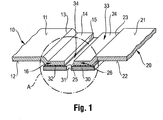
- FIG. 1 shows a sectional view of a structure consisting of a body panel 10 as a first surface part and a replacement plate 20 as a second surface part during the joining by means of the method according to the invention. Accordingly, the inventive method is not yet completed.
- a defective surface part has been separated and removed from the body panel 10 so that the body panel 10 has a free edge 15.
- a replacement for the defective surface part is to represent the replacement part 20, which is to be connected by means of the method according to the invention with the body panel 10.
- the body panel 10 has an outer side 11 and an inner side 12.
- the replacement part 20 has an outer side 21 and an inner side 22.
- the outside 11 was provided with a surface layer, not shown, in particular including a paint, the same was already removed from the shown part of the body panel 10.
- the body panel 10 has a deposition 14, which extends from a Absetzkante 13 in the direction of the free edge 15. After separating the damaged part, the body panel 10 has been deposited in one step by means of a Absetzzange so that the level of the outside 11 in the region of this offset 14 below the level of the outside 11 of the adjacent areas, ie the original level of the body part 10 lies.
- the Absetzkante 13 has a radius of 1mm
- the depth of the offset 14 is preferably at least the simple thickness of the body panel 10, in the present embodiment, about the simple strength.
- the frontal, lying in the direction of the free edge 15 region of the body panel 10 has been processed by a cold forming process. In the embodiment shown, this area has been designed to increase the strength of this area and / or reduce ductility and to break the sharpness of the free edge 15.
- the replacement plate 20 in turn, also has a free edge 25, which extends corresponding to the free edge 15 of the body panel 10 and in the illustrated position of the exchange plate 10 of the free edge 15 opposite.
- a corresponding extension is preferably to be understood as meaning a profile or a shape such that both edges 15, 25 preferably extend over the entire length at a more or less constant distance from one another, so that they are spaced apart in regions Arrangement of body panel 10 and replacement plate 20 to each other a regular gap 34 between the two free edges 15, 25 is present.
- the replacement plate 20 has a deposition 24, which extends from a Absetzkante 23 in the direction of the free edge 25.
- the replacement sheet 20 has been discontinued in one step by means of a Absetzzange so that the level of the outer side 21 in the region of this offset 24 below the level of the outside 21 of adjacent areas, ie the original level of the body part 20 is located.
- the Absetzkante 23 has also here a radius of 1 mm, the depth of the offset 24 is preferably at least the simple thickness of the replacement plate 20, in the present embodiment, approximately the simple strength.
- body panel 10 and replacement plate 20 are positioned to each other such that between the free edges 15, 25, a gap 34 is provided.
- the depositions 14, 24 together form a trough 33, the part of which may also be the gap 34, provided that it is not by a in FIG. 1 not shown connecting means is filled.
- the illustrated positioning of the body panel 10 and the replacement plate 20 is carried out using an adhesive 32 and a connection shoe 30 as a joining aid.
- the connecting shoe 30 in the present exemplary embodiment is a sheet metal sheet part which is dimensioned such that, in the position of the body panel 10 and the replacement panel 20, it is approximately as large as the total area of the two deployments 14, 24
- the connection shoe 30 comes to rest on the inner sides 12, 22 in the region of the shoulders 14, 24 of the body panel 10 and the replacement plate 20, wherein a layer of adhesive 32 is provided between the connection shoe 30 and the inner sides 12, 22 is. Therefore, the region of the deposits 14 of the body panel 10 is also identified as the joining region 16 of the body panel 10, the region of the offset 24 of the replacement metal sheet 20 also as the joining region 26 of the replacement metal sheet 20.
- connection shoe 30 As adhesive 32, a two-component epoxy-based body adhesive is used, as in particular in the WO2011048022 is described. The adhesive was applied to the surface of the connection shoe 30 prior to the placement of the connection shoe 30.
- the connecting shoe 30 is used as a joining aid, which at least partially overlaps the joining areas 16, 26 of the body panel 10 or the replacement panel 20, wherein the adhesive 32 in the positioning shown is between the joining areas 16, 26 and the connecting shoe 30 is provided.
- the method according to the invention provides for the provision of a mechanical joint for providing a mounting connection.
- the connecting shoe 30 is equipped in the present embodiment with a plurality of holes 31 to provide an attack area for a mechanical connection means, ie for the mechanical joint.
- the holes 31 are arranged such that they lie in the positioning of the components shown to each other within the gap 34 between the free edges 15, 25 and are accessible through the gap 34.
- the gap 34 and / or the Holes 31 preferably designed such that the gap is slightly larger than the diameter of the bores 31, preferably such that each bore 31 is freely accessible through the gap 34 by means of a mechanical connection means.
- the distance between the individual holes 31 to each other in the illustrated embodiment is 35mm and is generally in the range of 15mm to 50mm for the implementation of the method according to the invention.
- FIG. 2 shows a sectional view of a detail A of the construction of FIG. 1 in a further process step.
- the connection shoe 30 has been shown somewhat narrower than in FIG. 1 .
- the size of the sheet-driving screw 35 is selected such that an external thread 37 provided on the sheet-driving screw 35 does not touch the free edges 15, 25 in the region of the gap 34, but cuts into the wall of a bore 31 of the connection shoe 30. In this way, can be dispensed with an equipment of the bore 31 with an internal thread.
- a washer 38 has been provided which is dimensioned such that a screw head 36 presses the washer 38 when screwing the sheet driving screw 35 on the outer sides 11, 21 of both depositions 14, 24 to the inside of the joining areas 16th , 26 of the body panel 10 and thebuiltbleches 20 and the connecting shoe 30 with the adhesive 32 to provide a mounting connection compress, in particular to allow hardening of the adhesive 32 and a secure material connection of the parts to each other by means of the adhesive 32.
- the washer 38 other suitable power transmission means can be used, in particular suitable bracket or bridge-shaped components.
- the adhesive 32 is cured, wherein the use of, for example, an infrared radiator or a corresponding heating pad for heating the structure may prove useful.
- FIG. 3 shows a sectional side view of the structure FIG. 1 after completion of the method according to the invention, ie a connection region according to the invention.
- the adhesive 32 is in FIG. 2 shown lead screw 35 and the washer 38 has been removed.
- the bore 31 and the gap 34 have been freed from residues of adhesive 32.
- the outer side 11, 21 in particular in the region of the joining regions 16, 26 and the free edges 15, 25 have been treated at the gap 34 with a corrosion protection.
- a coating are suitable, as in the EP975439B1 is disclosed, which thus complements the present disclosure.
- Such coatings can be impregnated, for example, in cloths and thus serve as a quick and easy method for the pretreatment of metals.
- the wipes make pretreatment easier and faster turnaround times.
- the trough 33, the gap 34 and preferably also the bores 31 are then filled free of air using a filling compound 39, to a level balance, in particular the trough 33 to the level of the outside 11, 21 of the adjacent areas with respect to the settlements 14, 24 of the body panel 10 and the replacement sheet 20 to allow.
- a filling compound 39 which is used as a body filling compound for repairing bodywork damage and which is particularly suitable in the EP1672010A1 is described.
- the product can be processed at room temperature and then cured with an infrared heat source at preferably 60 to 80 degrees Celsius.
- the use of, for example, a heat source for heating the structure has proven to be useful, in the illustrated embodiment, a not shown heating pad has been used, which can adapt to the contour of the structure, the necessary curing temperature for the required curing time Provides its heat in the direction of the sheet metal parts 10, 20, so that the environment is not significantly heated. This has proven to be particularly advantageous because it is protected by the covering of the filling compound 39 during the hardening process against mechanical and other influences.
- another heat source can be used for curing the filling compound 39, such as, for example, a heating or infrared radiator.
- the outer surface of the filling compound 39 and the adjacent regions of the outer sides 11, 21 have already been processed in the embodiment shown and in particular painted, resulting in a surface layer 40 result.
- usual operations are used, such as grinding, filling, filling, priming, painting with a basecoat and painting with a clearcoat.
- FIG. 4 shows a sectional side view of a variant of a structure after completion of the method according to the invention, ie an alternative connection region according to the invention.
- the method used here is basically comparable to the method which with the FIG. 3 has shown construction.
- the body part 10 as the first surface part and the replacement part 20 have been connected or joined together as a second surface part here as well.
- Both the body part 10, and the replacement part 20 have also been provided with deposits 14, 24, wherein the radius of the deposition at the respective Absetzkanten 13, 23 is 2mm, so that the level of the outer sides 11, 21 in the region of these settlements 14th , 24 is below the level of the outside 11, 21 of the adjacent areas of the respective surface parts.
- the deposition of the 14 Body part 10 has approximately a depth of twice the thickness of the body panel 10, the offset 24 of the replacement part 20 again only a depth of about the simple thickness of the replacement plate 20.
- Both body panel 10, and replacement plate 20 have the same strength.
- the different depth of the recesses 14, 24 is explained in the illustrated positioning of the body panel 10 and the replacement plate 20 to each other.
- Both plates 10, 20 overlap one another such that the joining region 26 of the replacement plate 20 with the inner side 22 lies on the outer side 11 of the joining region 16 of the body panel 10, so that both depressions 14, 24 also form a depression 33 here.
- For cohesive connection of both sheets 10, 20 is in the space between the overlapping joining portions 16, 26 of the adhesive 32, also here preferably described above two-component epoxy-based body adhesive provided. In contrast to the embodiment of the FIGS. 1 to 3 Accordingly, no connection shoe is used here as a joining aid.
- the corresponding frontal, lying in the direction of the respective free edges 15, 25 regions of the respective joining regions 16, 26 of the body panel 10 and theandbleches 20 were further, preferably after settling and after the positioning shown using the adhesive 32 by a cold forming process, namely edited by Dengeln.
- the two joining areas 16, 26 have been provided with holes 17, 27 corresponding to one another in the position shown. These are to be understood to mean bores 17, 27, preferably of the same diameter, which are arranged concentrically with one another in the overlapping state of the joining areas 16, 26 shown. In each case, a plurality of holes 17, 27 are provided, preferably at a distance of 20mm each bore 17, 27 to the next of the same plate 10, 20.
- the holes 17, 27 are used to provide a mechanical joint in the trough 33 to provide a mounting connection for the curing of the adhesive 32, wherein in the illustrated embodiment, a rivet 42 is used.
- the rivet 42 extends with a rivet shank 44 through the bore 27, the replacement plate 20 and the bore 17 of the underlying body panel 10, wherein a setting head 43 of the rivet 42 rests on the outer side 21 of the joining region 26 of the replacement plate 20 and a closing head 45
- the rivet 42 presses the overlapping joining regions 16, 26 together, in particular to enable curing of the adhesive 32 and a secure cohesive connection of the sheets 10, 20 to each other by means of the adhesive 32.
- any adhesive 32 that might leak is preferably wiped.
- the adhesive 32 has been cured as described above.
- a further difference from the exemplary embodiment described above is that the rivet 42 has not been removed from the bores 17, 27 in particular after the curing of the adhesive 32. Rather, the setting head 43 and the immediately adjacent regions of the outside 21 of the joining region 26 are preferably provided with an adhesive 41 immediately after the fastening, in particular in order to be able to provide corrosion protection.
- the above-described two-component epoxy-based body adhesive can be used, so that preferably the adhesive 32 and the adhesive 41 can be cured together. After curing of the adhesives 32, 41, the outer side 11, 21 has been treated, in particular in the region of the joining regions 16, with a corrosion protection, for example with a coating, as described in US Pat EP975439B1 is disclosed.
- the trough 33 is further filled air-free subsequently using the filling compound 39 described above, to allow leveling in particular of the trough 33 to the level of the outside 11, 21 of the adjacent areas of the body panel 10 and the replacement plate 20.
- the outer surface of the filling compound 39 and the adjacent regions of the outer sides 11, 21 have been processed and in particular painted as described above, which results in a surface layer 40.
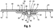
- FIG. 5 shows a sectional side view of another variant of a structure after completion of the method according to the invention, ie an alternative connection region according to the invention.
- the method for producing the illustrated construction of body panel 10 and replacement panel 20 corresponds to the method of construction FIG. 4 , so that reference is made to the above description, the extent to which the description of FIG. 5 illustrated embodiment added.
- One difference, however, is the configuration of the offset 14 of the body panel 10, which has a step 19, so that the deposition 14 is divided into two regions of different depths.
- the front region opens into the free edge 15 and has a depth which corresponds to twice the thickness of the body panel 10.
- This area represents the joining region 16 of the body panel 10, on the outer side 11 of the joining region 26 of the replacement plate 20 is positioned in the position shown, again an adhesive 32 between the joining regions 16, 26 is provided. Accordingly, in this first region of the offset 14, the joining regions 16, 26 overlap. On the side facing away from the free edge 15, said first region of the offset 14 terminates in the step 19 and transitions into a second region which, just like the offset 24 of the replacement plate 20, only has a depth corresponding to the simple thickness of the body panel 10. Both body panel 10, as well as replacement plate 20 have the same strength.
- the outer side 21 of the joining region 26 of the replacement plate 20 is therefore approximately in one plane with the outer side 11 of the joining region 16 of the second Range of deposition 14 of the body panel 10.
- FIG. 6 shows a sectional side view of a third variant of a structure after completion of the method according to the invention, ie an alternative connection region according to the invention.
- the method for producing the illustrated structure of body panel 10 and replacement plate 20 corresponds to the method of construction of the FIGS. 1 to 3 , so that reference is made to the above description, the extent to which the description of FIG. 6 illustrated embodiment added.
- a difference is the design of the settlements 14, 24 of the body panel 10 and the replacement sheet 20.
- the angle of the bevels 19, 29 to the corresponding output levels of the outer sides 11, 21 of the sheets 10, 20 is in the illustrated embodiment in each case 3 °. Generally, angles in the range of 1 ° to 10 ° are preferably used for the same slopes.
- a rivet 42 is used, which extends with its rivet shank 44 through the gap 34 lying between the two opposite free edges 15, 25 and extends through the bore 31 of the connecting shoe 30.
- the setting head 43 is in the installed state on the outer sides 11, 21 of the depositions 14, 24, so the outer sides 11, 21 of the joining areas 16, 26 of the body panel 10 and thefoundbleches 20 on.
- the closing head 45 in turn is positioned on the underside of the connecting shoe 30 such that the joining regions 16, 26 and the connecting shoe 30 are compressed to provide a mounting connection, in particular curing of the adhesive 32 and secure bonding of the parts to each other by means of the adhesive 32 to ensure.
- the rivet 42 remains in its position and is poured by means of the filling compound 39 after the above-described processing.
- the outer surface of the filling compound 39 and the adjacent regions of the outer sides 11, 21 have also been processed and, in particular, painted, as described above, resulting in a surface layer 40.
- 10 body sheet 29 slope 11 outside 30
- Parker screw 17 drilling 36 screw head 18 step 37 external thread 19 slope 38 washer 20 replacement sheet 39 filling compound 21 outside 40 surface layer 22 inside 41 adhesive 23 offset edge 42 rivet 24 deposition 43 setting head 25 free edge 44 rivet 26 joining area 45 closing head 27 drilling
Landscapes
- Engineering & Computer Science (AREA)
- Mechanical Engineering (AREA)
- General Engineering & Computer Science (AREA)
- Chemical & Material Sciences (AREA)
- Combustion & Propulsion (AREA)
- Transportation (AREA)
- Adhesives Or Adhesive Processes (AREA)
- Standing Axle, Rod, Or Tube Structures Coupled By Welding, Adhesion, Or Deposition (AREA)
- Connection Of Plates (AREA)
- Vehicle Cleaning, Maintenance, Repair, Refitting, And Outriggers (AREA)
Applications Claiming Priority (2)
| Application Number | Priority Date | Filing Date | Title |
|---|---|---|---|
| DE102013218495.6A DE102013218495A1 (de) | 2013-09-16 | 2013-09-16 | Fügeverfahren |
| PCT/EP2014/068241 WO2015036251A1 (de) | 2013-09-16 | 2014-08-28 | Fügeverfahren |
Publications (2)
| Publication Number | Publication Date |
|---|---|
| EP3046813A1 EP3046813A1 (de) | 2016-07-27 |
| EP3046813B1 true EP3046813B1 (de) | 2018-02-14 |
Family
ID=51422082
Family Applications (1)
| Application Number | Title | Priority Date | Filing Date |
|---|---|---|---|
| EP14756051.0A Active EP3046813B1 (de) | 2013-09-16 | 2014-08-28 | Fügeverfahren |
Country Status (9)
| Country | Link |
|---|---|
| US (1) | US10279784B2 (enExample) |
| EP (1) | EP3046813B1 (enExample) |
| JP (1) | JP6559140B2 (enExample) |
| KR (1) | KR101803217B1 (enExample) |
| CN (1) | CN105531163B (enExample) |
| AU (1) | AU2014320608B2 (enExample) |
| DE (1) | DE102013218495A1 (enExample) |
| ES (1) | ES2668703T3 (enExample) |
| WO (1) | WO2015036251A1 (enExample) |
Families Citing this family (16)
| Publication number | Priority date | Publication date | Assignee | Title |
|---|---|---|---|---|
| EP2860407B1 (de) * | 2013-10-08 | 2017-01-18 | MAGNA STEYR Fahrzeugtechnik AG & Co KG | Strukturbauteil |
| JP6109271B2 (ja) * | 2015-02-06 | 2017-04-05 | 株式会社神戸製鋼所 | 接合構造体、及び接合構造体の製造方法 |
| US10584727B2 (en) * | 2016-11-03 | 2020-03-10 | Ford Global Technologies, Llc | Multi-material restrainer joint |
| CN108216378B (zh) * | 2016-12-21 | 2022-01-14 | 丰田自动车株式会社 | 车辆面板结构 |
| WO2018234082A1 (de) * | 2017-06-22 | 2018-12-27 | Sika Technology Ag | Verbindung von elementen in kraftfahrzeugen |
| EP3428045A1 (de) * | 2017-07-13 | 2019-01-16 | Sika Technology Ag | Einkomponentiger hitzehärtender epoxidklebstoff hoher auswaschbeständigkeit |
| DE102017116116A1 (de) * | 2017-07-18 | 2019-01-24 | Webasto SE | Anordnung für ein Fahrzeugdach, Fahrzeugdach für ein Kraftfahrzeug und Verfahren zum Herstellen einer Anordnung für ein Fahrzeugdach |
| DE102017121975A1 (de) * | 2017-09-22 | 2019-03-28 | GEDIA Gebrüder Dingerkus GmbH | Verfahren zur Herstellung von Bauteilen aus Metallblech |
| US10864682B2 (en) | 2018-03-05 | 2020-12-15 | GM Global Technology Operations LLC | Method of joining of polymeric composites |
| CN109131593B (zh) * | 2018-07-23 | 2021-07-23 | 北京长城华冠汽车科技股份有限公司 | 地板及包括该地板的汽车 |
| EP3622846B1 (fr) * | 2018-09-14 | 2025-06-18 | Comadur S.A. | Procede d'assemblage d'au moins deux elements |
| JP7229850B2 (ja) * | 2019-05-20 | 2023-02-28 | 株式会社神戸製鋼所 | 車両用サイドドアの製造方法、ドア用部品及びサイドドア |
| EP3835036A1 (de) * | 2019-12-13 | 2021-06-16 | Sika Technology Ag | Vorfixierung zweier substrate |
| DE102020117015A1 (de) * | 2020-06-29 | 2021-12-30 | Man Truck & Bus Se | Reparaturverfahren für ein Karosserieteil und Absetzwerkzeug mit Spindeltrieb |
| DE102022117396A1 (de) * | 2022-07-12 | 2024-01-18 | Bayerische Motoren Werke Aktiengesellschaft | Bauteilverbund für eine Karosserie eines Kraftwagens sowie Verfahren zu dessen Herstellung |
| CN115415235B (zh) * | 2022-07-26 | 2024-06-14 | 沪东中华造船(集团)有限公司 | 一种用于薄膜罐不锈钢封板预粘连的处理方法 |
Family Cites Families (32)
| Publication number | Priority date | Publication date | Assignee | Title |
|---|---|---|---|---|
| DE1575156B2 (de) * | 1967-05-26 | 1972-10-19 | Hertel, Heinrich, Prof. Dr.-Ing., 1000 Berlin | Ausbildung einer kraefte uebertragenden klebeverbindung plattenfoermiger bauteile, z b blechen |
| US3655424A (en) * | 1968-05-24 | 1972-04-11 | Massachusetts Inst Technology | Adhesive tape |
| US4219980A (en) * | 1977-08-26 | 1980-09-02 | Rockwell International Corporation | Reinforced composite structure and method of fabrication thereof |
| JPS58156518U (ja) * | 1982-04-12 | 1983-10-19 | 株式会社日立製作所 | 集塵機 |
| NL190750C (nl) | 1984-06-21 | 1994-08-01 | Unilever Nv | Nikkelaluminaat katalysator, de bereiding daarvan en het hydrogeneren van onverzadigde organische verbindingen daarmee. |
| SE8505003L (sv) * | 1985-10-23 | 1987-04-24 | Folksam Auto Ab | Overlappslimfog |
| DE4120844C1 (enExample) | 1991-06-25 | 1992-11-12 | Audi Ag, 8070 Ingolstadt, De | |
| CN1121879A (zh) * | 1994-05-13 | 1996-05-08 | 陈运华 | 汽车车身外壳整形方法及专用夹板 |
| JPH08121442A (ja) * | 1994-10-26 | 1996-05-14 | Mitsubishi Electric Corp | 接着接合体及びその接合方法並びにリベット |
| DE19633911A1 (de) | 1996-08-22 | 1998-02-26 | Bayerische Motoren Werke Ag | Verfahren zur Reparatur einer Fahrzeugkarosserie |
| US5958511A (en) | 1997-04-18 | 1999-09-28 | Henkel Corporation | Process for touching up pretreated metal surfaces |
| DE19748786C2 (de) * | 1997-11-05 | 1999-10-21 | Daimler Chrysler Ag | Klebeverbindung von Blechteilen |
| JP2945383B1 (ja) * | 1998-06-05 | 1999-09-06 | 大東京火災海上保険株式会社 | 車輛修理方法 |
| DE19831982C2 (de) * | 1998-07-16 | 2003-04-10 | Daimler Chrysler Ag | Verfahren zur Verbindung von Blechbauteilen |
| WO2000032352A1 (en) * | 1998-11-27 | 2000-06-08 | Super Line Co., Ltd. | Sheet metal repair method, sheet metal repair tool, and sheet-like member fixing device |
| JP3187782B2 (ja) * | 1998-12-16 | 2001-07-11 | 有限会社オレンジプロダクションリミテッド | 金属板の接合方法 |
| TW470716B (en) * | 2000-09-20 | 2002-01-01 | Takao Motohashi | Sheet metal working methods for vehicles |
| JP2002193080A (ja) * | 2000-12-28 | 2002-07-10 | Super Line:Kk | 板金接合方法 |
| WO2003004327A1 (en) * | 2001-07-03 | 2003-01-16 | Lord Corporation | Procedure for repairing vehicle bodies with adhesively bonded replacement panels |
| US20030159264A1 (en) * | 2002-02-22 | 2003-08-28 | The Dow Chemical Company | Automotive roof module and method of assembly of the module to an automotive vehicle |
| DE10329231B3 (de) * | 2003-06-28 | 2005-03-24 | Forschungszentrum Karlsruhe Gmbh | Verbindung zwischen zwei Blechen |
| JP2005342739A (ja) * | 2004-06-01 | 2005-12-15 | Nissan Motor Co Ltd | 金属板の接合方法および接合構造 |
| JP2006103242A (ja) * | 2004-10-07 | 2006-04-20 | Meguro Kagaku Kogyo Kk | ポリプロピレン樹脂部の補修方法 |
| DE102004060783A1 (de) | 2004-12-17 | 2006-06-29 | Henkel Kgaa | 2 K Versteifungsmaterial für Außenhautanwendungen |
| US9189960B2 (en) * | 2006-05-31 | 2015-11-17 | Manheim Investments, Inc. | Computer-based technology for aiding the repair of motor vehicles |
| JP5155859B2 (ja) * | 2006-07-05 | 2013-03-06 | 川真田 博康 | 金属板の接合方法 |
| JP2008138851A (ja) * | 2006-12-05 | 2008-06-19 | Fukui Byora Co Ltd | ブラインドリベット |
| US8181327B2 (en) * | 2008-02-08 | 2012-05-22 | Zephyros, Inc | Mechanical method for improving bond joint strength |
| DE102009045903A1 (de) | 2009-10-21 | 2011-04-28 | Henkel Ag & Co. Kgaa | Schlagzähe, bei Raumtemperatur härtende zweikomponentige Masse auf Epoxidbasis |
| WO2012149379A2 (en) * | 2011-04-28 | 2012-11-01 | Zin Technologies, Inc. | Bonded and stitched composite structure |
| US10471910B2 (en) * | 2014-12-18 | 2019-11-12 | Faurecia Interior Systems, Inc. | Vehicle interior panel with sculpted surface |
| US10584727B2 (en) * | 2016-11-03 | 2020-03-10 | Ford Global Technologies, Llc | Multi-material restrainer joint |
-
2013
- 2013-09-16 DE DE102013218495.6A patent/DE102013218495A1/de not_active Ceased
-
2014
- 2014-08-28 CN CN201480050693.3A patent/CN105531163B/zh active Active
- 2014-08-28 EP EP14756051.0A patent/EP3046813B1/de active Active
- 2014-08-28 KR KR1020167009957A patent/KR101803217B1/ko not_active Expired - Fee Related
- 2014-08-28 JP JP2016541872A patent/JP6559140B2/ja not_active Expired - Fee Related
- 2014-08-28 WO PCT/EP2014/068241 patent/WO2015036251A1/de not_active Ceased
- 2014-08-28 ES ES14756051.0T patent/ES2668703T3/es active Active
- 2014-08-28 AU AU2014320608A patent/AU2014320608B2/en not_active Ceased
-
2016
- 2016-03-14 US US15/069,359 patent/US10279784B2/en active Active
Also Published As
| Publication number | Publication date |
|---|---|
| DE102013218495A1 (de) | 2015-03-19 |
| KR101803217B1 (ko) | 2017-11-29 |
| AU2014320608B2 (en) | 2017-12-14 |
| KR20160057459A (ko) | 2016-05-23 |
| US10279784B2 (en) | 2019-05-07 |
| ES2668703T3 (es) | 2018-05-21 |
| JP6559140B2 (ja) | 2019-08-14 |
| JP2016536212A (ja) | 2016-11-24 |
| WO2015036251A1 (de) | 2015-03-19 |
| US20160193988A1 (en) | 2016-07-07 |
| CN105531163A (zh) | 2016-04-27 |
| EP3046813A1 (de) | 2016-07-27 |
| CN105531163B (zh) | 2018-07-10 |
| AU2014320608A1 (en) | 2016-04-07 |
Similar Documents
| Publication | Publication Date | Title |
|---|---|---|
| EP3046813B1 (de) | Fügeverfahren | |
| WO2011141339A1 (de) | Biegeverfahren und biegevorrichtung | |
| EP2893201B1 (de) | Verfahren zum herstellen einer bördelnaht | |
| EP2360036A1 (de) | Kraftfahrzeugbauteil und Verfahren zu seiner Herstellung | |
| EP2480444B1 (de) | Kraftfahrzeug mit miteinander verbundenen aussenhautbauteilen sowie ein verfahren zur verbindung von aussenhautbauteilen | |
| DE102008000517B4 (de) | Verfahren zum druckdichten Fügen eines metallischen Lenkgetriebegehäuses mit einem Kunststoffgehäusedeckel | |
| DE102006056489A1 (de) | Verfahren zur Herstellung eines Stahl-/Aluminium-Verbundbauteils | |
| DE102013108702B4 (de) | Verfahren zum Verbinden eines Sandwichbleches mit einem metallischen Bauteil und Karosserieteil mit einem Sandwichblech als Außenblech und einem metallischen Bauteil | |
| DE102007062087A1 (de) | Hybridfügeverfahren für Überlappverbindungen | |
| DE102018131052B4 (de) | Verfahren zur Herstellung eines Bauteilverbunds und Kraftfahrzeug | |
| DE102009043854A1 (de) | Geklebte Blechteilanordnung mit integrierter Versiegelung | |
| DE102015100968A1 (de) | Verfahren zur Herstellung einer Kraftfahrzeugkarosserie in Mischbauweise | |
| DE202012103728U1 (de) | Energieabsorptionsbauteil für ein Fahrzeug sowie Stoßfängerbaugruppe umfassend ein solches Bauteil und einen Stoßfängerquerträger | |
| DE19831982A1 (de) | Verfahren zur Verbindung von Blechbauteilen | |
| DE10052108B4 (de) | Verfahren zum Abdichten von Blechfügespalten | |
| EP3228416A1 (de) | Verfahren und vorrichtung zum herstellen einer hybridverbindung sowie damit hergestelltes karosseriebauteil | |
| DE19806710C2 (de) | Verfahren zur Sanierung von Stahlkonstruktionen | |
| DE102009032651A1 (de) | Verfahren zur Herstellung einer Karosserie für ein Kraftfahrzeug und Karosserie | |
| DE102019125313B4 (de) | Fahrzeug mit ausgebessertem Sandwichpaneel, Verfahren und Reparatursatz dafür | |
| DE102014013211A1 (de) | Verfahren zur Herstellung einer Falzverbindung zwischen einem Innenteil und einem Außenteil | |
| DE102014108183B4 (de) | Mehrschichtige Karosseriestruktur einer Kraftfahrzeugkarosserie und Verfahren zur Herstellung der mehrschichtigen Karosseriestruktur | |
| DE102004008108A1 (de) | Überlappstoß zum Schweißen von beschichteten Werkstücken | |
| WO2011134618A1 (de) | Karosseriestruktur eines kraftfahrzeuges mit t-förmigen stützprofil, verfahren zur herstellung der karosseriestruktur und karosserie oder karosserieanbauteil | |
| DE102009049752A1 (de) | Herstellung einer versiegelten Schnittkante an einem Blechwerkstoff | |
| DE10223329B4 (de) | Verfahren zum stirnseitigen Fügen eines Hohlprofils an ein anderes Profil für eine Rahmenstruktur einer Fahrzeugkarosserie |
Legal Events
| Date | Code | Title | Description |
|---|---|---|---|
| PUAI | Public reference made under article 153(3) epc to a published international application that has entered the european phase |
Free format text: ORIGINAL CODE: 0009012 |
|
| 17P | Request for examination filed |
Effective date: 20160217 |
|
| AK | Designated contracting states |
Kind code of ref document: A1 Designated state(s): AL AT BE BG CH CY CZ DE DK EE ES FI FR GB GR HR HU IE IS IT LI LT LU LV MC MK MT NL NO PL PT RO RS SE SI SK SM TR |
|
| AX | Request for extension of the european patent |
Extension state: BA ME |
|
| DAX | Request for extension of the european patent (deleted) | ||
| GRAJ | Information related to disapproval of communication of intention to grant by the applicant or resumption of examination proceedings by the epo deleted |
Free format text: ORIGINAL CODE: EPIDOSDIGR1 |
|
| GRAP | Despatch of communication of intention to grant a patent |
Free format text: ORIGINAL CODE: EPIDOSNIGR1 |
|
| INTG | Intention to grant announced |
Effective date: 20170830 |
|
| RIN1 | Information on inventor provided before grant (corrected) |
Inventor name: SCHWARZE, HERMANN J. Inventor name: PLOTZITZKA, JOACHIM |
|
| GRAS | Grant fee paid |
Free format text: ORIGINAL CODE: EPIDOSNIGR3 |
|
| GRAA | (expected) grant |
Free format text: ORIGINAL CODE: 0009210 |
|
| AK | Designated contracting states |
Kind code of ref document: B1 Designated state(s): AL AT BE BG CH CY CZ DE DK EE ES FI FR GB GR HR HU IE IS IT LI LT LU LV MC MK MT NL NO PL PT RO RS SE SI SK SM TR |
|
| REG | Reference to a national code |
Ref country code: GB Ref legal event code: FG4D Free format text: NOT ENGLISH |
|
| REG | Reference to a national code |
Ref country code: CH Ref legal event code: EP |
|
| REG | Reference to a national code |
Ref country code: IE Ref legal event code: FG4D Free format text: LANGUAGE OF EP DOCUMENT: GERMAN |
|
| REG | Reference to a national code |
Ref country code: DE Ref legal event code: R096 Ref document number: 502014007263 Country of ref document: DE Ref country code: AT Ref legal event code: REF Ref document number: 969637 Country of ref document: AT Kind code of ref document: T Effective date: 20180315 |
|
| REG | Reference to a national code |
Ref country code: ES Ref legal event code: FG2A Ref document number: 2668703 Country of ref document: ES Kind code of ref document: T3 Effective date: 20180521 |
|
| REG | Reference to a national code |
Ref country code: NL Ref legal event code: MP Effective date: 20180214 |
|
| PG25 | Lapsed in a contracting state [announced via postgrant information from national office to epo] |
Ref country code: NO Free format text: LAPSE BECAUSE OF FAILURE TO SUBMIT A TRANSLATION OF THE DESCRIPTION OR TO PAY THE FEE WITHIN THE PRESCRIBED TIME-LIMIT Effective date: 20180514 Ref country code: CY Free format text: LAPSE BECAUSE OF FAILURE TO SUBMIT A TRANSLATION OF THE DESCRIPTION OR TO PAY THE FEE WITHIN THE PRESCRIBED TIME-LIMIT Effective date: 20180214 Ref country code: HR Free format text: LAPSE BECAUSE OF FAILURE TO SUBMIT A TRANSLATION OF THE DESCRIPTION OR TO PAY THE FEE WITHIN THE PRESCRIBED TIME-LIMIT Effective date: 20180214 Ref country code: FI Free format text: LAPSE BECAUSE OF FAILURE TO SUBMIT A TRANSLATION OF THE DESCRIPTION OR TO PAY THE FEE WITHIN THE PRESCRIBED TIME-LIMIT Effective date: 20180214 Ref country code: NL Free format text: LAPSE BECAUSE OF FAILURE TO SUBMIT A TRANSLATION OF THE DESCRIPTION OR TO PAY THE FEE WITHIN THE PRESCRIBED TIME-LIMIT Effective date: 20180214 Ref country code: LT Free format text: LAPSE BECAUSE OF FAILURE TO SUBMIT A TRANSLATION OF THE DESCRIPTION OR TO PAY THE FEE WITHIN THE PRESCRIBED TIME-LIMIT Effective date: 20180214 |
|
| REG | Reference to a national code |
Ref country code: FR Ref legal event code: PLFP Year of fee payment: 5 |
|
| PG25 | Lapsed in a contracting state [announced via postgrant information from national office to epo] |
Ref country code: RS Free format text: LAPSE BECAUSE OF FAILURE TO SUBMIT A TRANSLATION OF THE DESCRIPTION OR TO PAY THE FEE WITHIN THE PRESCRIBED TIME-LIMIT Effective date: 20180214 Ref country code: GR Free format text: LAPSE BECAUSE OF FAILURE TO SUBMIT A TRANSLATION OF THE DESCRIPTION OR TO PAY THE FEE WITHIN THE PRESCRIBED TIME-LIMIT Effective date: 20180515 Ref country code: BG Free format text: LAPSE BECAUSE OF FAILURE TO SUBMIT A TRANSLATION OF THE DESCRIPTION OR TO PAY THE FEE WITHIN THE PRESCRIBED TIME-LIMIT Effective date: 20180514 Ref country code: LV Free format text: LAPSE BECAUSE OF FAILURE TO SUBMIT A TRANSLATION OF THE DESCRIPTION OR TO PAY THE FEE WITHIN THE PRESCRIBED TIME-LIMIT Effective date: 20180214 Ref country code: SE Free format text: LAPSE BECAUSE OF FAILURE TO SUBMIT A TRANSLATION OF THE DESCRIPTION OR TO PAY THE FEE WITHIN THE PRESCRIBED TIME-LIMIT Effective date: 20180214 |
|
| PG25 | Lapsed in a contracting state [announced via postgrant information from national office to epo] |
Ref country code: MT Free format text: LAPSE BECAUSE OF FAILURE TO SUBMIT A TRANSLATION OF THE DESCRIPTION OR TO PAY THE FEE WITHIN THE PRESCRIBED TIME-LIMIT Effective date: 20180214 |
|
| PG25 | Lapsed in a contracting state [announced via postgrant information from national office to epo] |
Ref country code: EE Free format text: LAPSE BECAUSE OF FAILURE TO SUBMIT A TRANSLATION OF THE DESCRIPTION OR TO PAY THE FEE WITHIN THE PRESCRIBED TIME-LIMIT Effective date: 20180214 Ref country code: RO Free format text: LAPSE BECAUSE OF FAILURE TO SUBMIT A TRANSLATION OF THE DESCRIPTION OR TO PAY THE FEE WITHIN THE PRESCRIBED TIME-LIMIT Effective date: 20180214 Ref country code: IT Free format text: LAPSE BECAUSE OF FAILURE TO SUBMIT A TRANSLATION OF THE DESCRIPTION OR TO PAY THE FEE WITHIN THE PRESCRIBED TIME-LIMIT Effective date: 20180214 Ref country code: PL Free format text: LAPSE BECAUSE OF FAILURE TO SUBMIT A TRANSLATION OF THE DESCRIPTION OR TO PAY THE FEE WITHIN THE PRESCRIBED TIME-LIMIT Effective date: 20180214 Ref country code: AL Free format text: LAPSE BECAUSE OF FAILURE TO SUBMIT A TRANSLATION OF THE DESCRIPTION OR TO PAY THE FEE WITHIN THE PRESCRIBED TIME-LIMIT Effective date: 20180214 |
|
| REG | Reference to a national code |
Ref country code: DE Ref legal event code: R097 Ref document number: 502014007263 Country of ref document: DE |
|
| PG25 | Lapsed in a contracting state [announced via postgrant information from national office to epo] |
Ref country code: CZ Free format text: LAPSE BECAUSE OF FAILURE TO SUBMIT A TRANSLATION OF THE DESCRIPTION OR TO PAY THE FEE WITHIN THE PRESCRIBED TIME-LIMIT Effective date: 20180214 Ref country code: SK Free format text: LAPSE BECAUSE OF FAILURE TO SUBMIT A TRANSLATION OF THE DESCRIPTION OR TO PAY THE FEE WITHIN THE PRESCRIBED TIME-LIMIT Effective date: 20180214 Ref country code: DK Free format text: LAPSE BECAUSE OF FAILURE TO SUBMIT A TRANSLATION OF THE DESCRIPTION OR TO PAY THE FEE WITHIN THE PRESCRIBED TIME-LIMIT Effective date: 20180214 Ref country code: SM Free format text: LAPSE BECAUSE OF FAILURE TO SUBMIT A TRANSLATION OF THE DESCRIPTION OR TO PAY THE FEE WITHIN THE PRESCRIBED TIME-LIMIT Effective date: 20180214 |
|
| PLBE | No opposition filed within time limit |
Free format text: ORIGINAL CODE: 0009261 |
|
| STAA | Information on the status of an ep patent application or granted ep patent |
Free format text: STATUS: NO OPPOSITION FILED WITHIN TIME LIMIT |
|
| 26N | No opposition filed |
Effective date: 20181115 |
|
| PG25 | Lapsed in a contracting state [announced via postgrant information from national office to epo] |
Ref country code: SI Free format text: LAPSE BECAUSE OF FAILURE TO SUBMIT A TRANSLATION OF THE DESCRIPTION OR TO PAY THE FEE WITHIN THE PRESCRIBED TIME-LIMIT Effective date: 20180214 |
|
| PG25 | Lapsed in a contracting state [announced via postgrant information from national office to epo] |
Ref country code: MC Free format text: LAPSE BECAUSE OF FAILURE TO SUBMIT A TRANSLATION OF THE DESCRIPTION OR TO PAY THE FEE WITHIN THE PRESCRIBED TIME-LIMIT Effective date: 20180214 |
|
| PG25 | Lapsed in a contracting state [announced via postgrant information from national office to epo] |
Ref country code: LU Free format text: LAPSE BECAUSE OF NON-PAYMENT OF DUE FEES Effective date: 20180828 |
|
| REG | Reference to a national code |
Ref country code: BE Ref legal event code: MM Effective date: 20180831 |
|
| PG25 | Lapsed in a contracting state [announced via postgrant information from national office to epo] |
Ref country code: BE Free format text: LAPSE BECAUSE OF NON-PAYMENT OF DUE FEES Effective date: 20180831 |
|
| PGFP | Annual fee paid to national office [announced via postgrant information from national office to epo] |
Ref country code: ES Payment date: 20190924 Year of fee payment: 6 Ref country code: FR Payment date: 20190822 Year of fee payment: 6 |
|
| PGFP | Annual fee paid to national office [announced via postgrant information from national office to epo] |
Ref country code: GB Payment date: 20190821 Year of fee payment: 6 Ref country code: AT Payment date: 20190822 Year of fee payment: 6 |
|
| PGFP | Annual fee paid to national office [announced via postgrant information from national office to epo] |
Ref country code: CH Payment date: 20190821 Year of fee payment: 6 |
|
| PG25 | Lapsed in a contracting state [announced via postgrant information from national office to epo] |
Ref country code: TR Free format text: LAPSE BECAUSE OF FAILURE TO SUBMIT A TRANSLATION OF THE DESCRIPTION OR TO PAY THE FEE WITHIN THE PRESCRIBED TIME-LIMIT Effective date: 20180214 |
|
| PG25 | Lapsed in a contracting state [announced via postgrant information from national office to epo] |
Ref country code: PT Free format text: LAPSE BECAUSE OF FAILURE TO SUBMIT A TRANSLATION OF THE DESCRIPTION OR TO PAY THE FEE WITHIN THE PRESCRIBED TIME-LIMIT Effective date: 20180214 |
|
| PG25 | Lapsed in a contracting state [announced via postgrant information from national office to epo] |
Ref country code: MK Free format text: LAPSE BECAUSE OF NON-PAYMENT OF DUE FEES Effective date: 20180214 Ref country code: IE Free format text: LAPSE BECAUSE OF NON-PAYMENT OF DUE FEES Effective date: 20180828 Ref country code: HU Free format text: LAPSE BECAUSE OF FAILURE TO SUBMIT A TRANSLATION OF THE DESCRIPTION OR TO PAY THE FEE WITHIN THE PRESCRIBED TIME-LIMIT; INVALID AB INITIO Effective date: 20140828 |
|
| PG25 | Lapsed in a contracting state [announced via postgrant information from national office to epo] |
Ref country code: IS Free format text: LAPSE BECAUSE OF FAILURE TO SUBMIT A TRANSLATION OF THE DESCRIPTION OR TO PAY THE FEE WITHIN THE PRESCRIBED TIME-LIMIT Effective date: 20180614 |
|
| REG | Reference to a national code |
Ref country code: CH Ref legal event code: PL |
|
| REG | Reference to a national code |
Ref country code: AT Ref legal event code: MM01 Ref document number: 969637 Country of ref document: AT Kind code of ref document: T Effective date: 20200828 |
|
| GBPC | Gb: european patent ceased through non-payment of renewal fee |
Effective date: 20200828 |
|
| PG25 | Lapsed in a contracting state [announced via postgrant information from national office to epo] |
Ref country code: CH Free format text: LAPSE BECAUSE OF NON-PAYMENT OF DUE FEES Effective date: 20200831 Ref country code: LI Free format text: LAPSE BECAUSE OF NON-PAYMENT OF DUE FEES Effective date: 20200831 |
|
| PG25 | Lapsed in a contracting state [announced via postgrant information from national office to epo] |
Ref country code: AT Free format text: LAPSE BECAUSE OF NON-PAYMENT OF DUE FEES Effective date: 20200828 |
|
| PG25 | Lapsed in a contracting state [announced via postgrant information from national office to epo] |
Ref country code: FR Free format text: LAPSE BECAUSE OF NON-PAYMENT OF DUE FEES Effective date: 20200831 |
|
| PG25 | Lapsed in a contracting state [announced via postgrant information from national office to epo] |
Ref country code: GB Free format text: LAPSE BECAUSE OF NON-PAYMENT OF DUE FEES Effective date: 20200828 |
|
| REG | Reference to a national code |
Ref country code: ES Ref legal event code: FD2A Effective date: 20220110 |
|
| PG25 | Lapsed in a contracting state [announced via postgrant information from national office to epo] |
Ref country code: ES Free format text: LAPSE BECAUSE OF NON-PAYMENT OF DUE FEES Effective date: 20200829 |
|
| P01 | Opt-out of the competence of the unified patent court (upc) registered |
Effective date: 20230530 |
|
| PGFP | Annual fee paid to national office [announced via postgrant information from national office to epo] |
Ref country code: DE Payment date: 20250820 Year of fee payment: 12 |