EP3045367A1 - Système et procédé de commande de véhicule hybride - Google Patents
Système et procédé de commande de véhicule hybride Download PDFInfo
- Publication number
- EP3045367A1 EP3045367A1 EP14842854.3A EP14842854A EP3045367A1 EP 3045367 A1 EP3045367 A1 EP 3045367A1 EP 14842854 A EP14842854 A EP 14842854A EP 3045367 A1 EP3045367 A1 EP 3045367A1
- Authority
- EP
- European Patent Office
- Prior art keywords
- engine
- power
- mode
- hybrid electric
- electric vehicle
- Prior art date
- Legal status (The legal status is an assumption and is not a legal conclusion. Google has not performed a legal analysis and makes no representation as to the accuracy of the status listed.)
- Withdrawn
Links
Images


Classifications
-
- B—PERFORMING OPERATIONS; TRANSPORTING
- B60—VEHICLES IN GENERAL
- B60W—CONJOINT CONTROL OF VEHICLE SUB-UNITS OF DIFFERENT TYPE OR DIFFERENT FUNCTION; CONTROL SYSTEMS SPECIALLY ADAPTED FOR HYBRID VEHICLES; ROAD VEHICLE DRIVE CONTROL SYSTEMS FOR PURPOSES NOT RELATED TO THE CONTROL OF A PARTICULAR SUB-UNIT
- B60W20/00—Control systems specially adapted for hybrid vehicles
- B60W20/10—Controlling the power contribution of each of the prime movers to meet required power demand
- B60W20/15—Control strategies specially adapted for achieving a particular effect
-
- B—PERFORMING OPERATIONS; TRANSPORTING
- B60—VEHICLES IN GENERAL
- B60W—CONJOINT CONTROL OF VEHICLE SUB-UNITS OF DIFFERENT TYPE OR DIFFERENT FUNCTION; CONTROL SYSTEMS SPECIALLY ADAPTED FOR HYBRID VEHICLES; ROAD VEHICLE DRIVE CONTROL SYSTEMS FOR PURPOSES NOT RELATED TO THE CONTROL OF A PARTICULAR SUB-UNIT
- B60W10/00—Conjoint control of vehicle sub-units of different type or different function
- B60W10/04—Conjoint control of vehicle sub-units of different type or different function including control of propulsion units
- B60W10/06—Conjoint control of vehicle sub-units of different type or different function including control of propulsion units including control of combustion engines
-
- B—PERFORMING OPERATIONS; TRANSPORTING
- B60—VEHICLES IN GENERAL
- B60W—CONJOINT CONTROL OF VEHICLE SUB-UNITS OF DIFFERENT TYPE OR DIFFERENT FUNCTION; CONTROL SYSTEMS SPECIALLY ADAPTED FOR HYBRID VEHICLES; ROAD VEHICLE DRIVE CONTROL SYSTEMS FOR PURPOSES NOT RELATED TO THE CONTROL OF A PARTICULAR SUB-UNIT
- B60W10/00—Conjoint control of vehicle sub-units of different type or different function
- B60W10/04—Conjoint control of vehicle sub-units of different type or different function including control of propulsion units
- B60W10/08—Conjoint control of vehicle sub-units of different type or different function including control of propulsion units including control of electric propulsion units, e.g. motors or generators
-
- B—PERFORMING OPERATIONS; TRANSPORTING
- B60—VEHICLES IN GENERAL
- B60W—CONJOINT CONTROL OF VEHICLE SUB-UNITS OF DIFFERENT TYPE OR DIFFERENT FUNCTION; CONTROL SYSTEMS SPECIALLY ADAPTED FOR HYBRID VEHICLES; ROAD VEHICLE DRIVE CONTROL SYSTEMS FOR PURPOSES NOT RELATED TO THE CONTROL OF A PARTICULAR SUB-UNIT
- B60W10/00—Conjoint control of vehicle sub-units of different type or different function
- B60W10/24—Conjoint control of vehicle sub-units of different type or different function including control of energy storage means
- B60W10/26—Conjoint control of vehicle sub-units of different type or different function including control of energy storage means for electrical energy, e.g. batteries or capacitors
-
- B—PERFORMING OPERATIONS; TRANSPORTING
- B60—VEHICLES IN GENERAL
- B60W—CONJOINT CONTROL OF VEHICLE SUB-UNITS OF DIFFERENT TYPE OR DIFFERENT FUNCTION; CONTROL SYSTEMS SPECIALLY ADAPTED FOR HYBRID VEHICLES; ROAD VEHICLE DRIVE CONTROL SYSTEMS FOR PURPOSES NOT RELATED TO THE CONTROL OF A PARTICULAR SUB-UNIT
- B60W20/00—Control systems specially adapted for hybrid vehicles
- B60W20/10—Controlling the power contribution of each of the prime movers to meet required power demand
- B60W20/13—Controlling the power contribution of each of the prime movers to meet required power demand in order to stay within battery power input or output limits; in order to prevent overcharging or battery depletion
-
- B—PERFORMING OPERATIONS; TRANSPORTING
- B60—VEHICLES IN GENERAL
- B60W—CONJOINT CONTROL OF VEHICLE SUB-UNITS OF DIFFERENT TYPE OR DIFFERENT FUNCTION; CONTROL SYSTEMS SPECIALLY ADAPTED FOR HYBRID VEHICLES; ROAD VEHICLE DRIVE CONTROL SYSTEMS FOR PURPOSES NOT RELATED TO THE CONTROL OF A PARTICULAR SUB-UNIT
- B60W20/00—Control systems specially adapted for hybrid vehicles
- B60W20/40—Controlling the engagement or disengagement of prime movers, e.g. for transition between prime movers
-
- B—PERFORMING OPERATIONS; TRANSPORTING
- B60—VEHICLES IN GENERAL
- B60W—CONJOINT CONTROL OF VEHICLE SUB-UNITS OF DIFFERENT TYPE OR DIFFERENT FUNCTION; CONTROL SYSTEMS SPECIALLY ADAPTED FOR HYBRID VEHICLES; ROAD VEHICLE DRIVE CONTROL SYSTEMS FOR PURPOSES NOT RELATED TO THE CONTROL OF A PARTICULAR SUB-UNIT
- B60W30/00—Purposes of road vehicle drive control systems not related to the control of a particular sub-unit, e.g. of systems using conjoint control of vehicle sub-units
- B60W30/18—Propelling the vehicle
- B60W30/18009—Propelling the vehicle related to particular drive situations
- B60W30/18018—Start-stop drive, e.g. in a traffic jam
-
- B—PERFORMING OPERATIONS; TRANSPORTING
- B60—VEHICLES IN GENERAL
- B60W—CONJOINT CONTROL OF VEHICLE SUB-UNITS OF DIFFERENT TYPE OR DIFFERENT FUNCTION; CONTROL SYSTEMS SPECIALLY ADAPTED FOR HYBRID VEHICLES; ROAD VEHICLE DRIVE CONTROL SYSTEMS FOR PURPOSES NOT RELATED TO THE CONTROL OF A PARTICULAR SUB-UNIT
- B60W30/00—Purposes of road vehicle drive control systems not related to the control of a particular sub-unit, e.g. of systems using conjoint control of vehicle sub-units
- B60W30/18—Propelling the vehicle
- B60W30/18009—Propelling the vehicle related to particular drive situations
- B60W30/18054—Propelling the vehicle related to particular drive situations at stand still, e.g. engine in idling state
-
- B—PERFORMING OPERATIONS; TRANSPORTING
- B60—VEHICLES IN GENERAL
- B60W—CONJOINT CONTROL OF VEHICLE SUB-UNITS OF DIFFERENT TYPE OR DIFFERENT FUNCTION; CONTROL SYSTEMS SPECIALLY ADAPTED FOR HYBRID VEHICLES; ROAD VEHICLE DRIVE CONTROL SYSTEMS FOR PURPOSES NOT RELATED TO THE CONTROL OF A PARTICULAR SUB-UNIT
- B60W30/00—Purposes of road vehicle drive control systems not related to the control of a particular sub-unit, e.g. of systems using conjoint control of vehicle sub-units
- B60W30/18—Propelling the vehicle
- B60W30/182—Selecting between different operative modes, e.g. comfort and performance modes
-
- B—PERFORMING OPERATIONS; TRANSPORTING
- B60—VEHICLES IN GENERAL
- B60K—ARRANGEMENT OR MOUNTING OF PROPULSION UNITS OR OF TRANSMISSIONS IN VEHICLES; ARRANGEMENT OR MOUNTING OF PLURAL DIVERSE PRIME-MOVERS IN VEHICLES; AUXILIARY DRIVES FOR VEHICLES; INSTRUMENTATION OR DASHBOARDS FOR VEHICLES; ARRANGEMENTS IN CONNECTION WITH COOLING, AIR INTAKE, GAS EXHAUST OR FUEL SUPPLY OF PROPULSION UNITS IN VEHICLES
- B60K6/00—Arrangement or mounting of plural diverse prime-movers for mutual or common propulsion, e.g. hybrid propulsion systems comprising electric motors and internal combustion engines
- B60K6/20—Arrangement or mounting of plural diverse prime-movers for mutual or common propulsion, e.g. hybrid propulsion systems comprising electric motors and internal combustion engines the prime-movers consisting of electric motors and internal combustion engines, e.g. HEVs
- B60K6/42—Arrangement or mounting of plural diverse prime-movers for mutual or common propulsion, e.g. hybrid propulsion systems comprising electric motors and internal combustion engines the prime-movers consisting of electric motors and internal combustion engines, e.g. HEVs characterised by the architecture of the hybrid electric vehicle
- B60K6/48—Parallel type
- B60K2006/4808—Electric machine connected or connectable to gearbox output shaft
-
- B—PERFORMING OPERATIONS; TRANSPORTING
- B60—VEHICLES IN GENERAL
- B60K—ARRANGEMENT OR MOUNTING OF PROPULSION UNITS OR OF TRANSMISSIONS IN VEHICLES; ARRANGEMENT OR MOUNTING OF PLURAL DIVERSE PRIME-MOVERS IN VEHICLES; AUXILIARY DRIVES FOR VEHICLES; INSTRUMENTATION OR DASHBOARDS FOR VEHICLES; ARRANGEMENTS IN CONNECTION WITH COOLING, AIR INTAKE, GAS EXHAUST OR FUEL SUPPLY OF PROPULSION UNITS IN VEHICLES
- B60K6/00—Arrangement or mounting of plural diverse prime-movers for mutual or common propulsion, e.g. hybrid propulsion systems comprising electric motors and internal combustion engines
- B60K6/20—Arrangement or mounting of plural diverse prime-movers for mutual or common propulsion, e.g. hybrid propulsion systems comprising electric motors and internal combustion engines the prime-movers consisting of electric motors and internal combustion engines, e.g. HEVs
- B60K6/42—Arrangement or mounting of plural diverse prime-movers for mutual or common propulsion, e.g. hybrid propulsion systems comprising electric motors and internal combustion engines the prime-movers consisting of electric motors and internal combustion engines, e.g. HEVs characterised by the architecture of the hybrid electric vehicle
- B60K6/48—Parallel type
-
- B—PERFORMING OPERATIONS; TRANSPORTING
- B60—VEHICLES IN GENERAL
- B60W—CONJOINT CONTROL OF VEHICLE SUB-UNITS OF DIFFERENT TYPE OR DIFFERENT FUNCTION; CONTROL SYSTEMS SPECIALLY ADAPTED FOR HYBRID VEHICLES; ROAD VEHICLE DRIVE CONTROL SYSTEMS FOR PURPOSES NOT RELATED TO THE CONTROL OF A PARTICULAR SUB-UNIT
- B60W2510/00—Input parameters relating to a particular sub-units
- B60W2510/24—Energy storage means
- B60W2510/242—Energy storage means for electrical energy
- B60W2510/244—Charge state
-
- B—PERFORMING OPERATIONS; TRANSPORTING
- B60—VEHICLES IN GENERAL
- B60W—CONJOINT CONTROL OF VEHICLE SUB-UNITS OF DIFFERENT TYPE OR DIFFERENT FUNCTION; CONTROL SYSTEMS SPECIALLY ADAPTED FOR HYBRID VEHICLES; ROAD VEHICLE DRIVE CONTROL SYSTEMS FOR PURPOSES NOT RELATED TO THE CONTROL OF A PARTICULAR SUB-UNIT
- B60W2520/00—Input parameters relating to overall vehicle dynamics
- B60W2520/04—Vehicle stop
-
- B—PERFORMING OPERATIONS; TRANSPORTING
- B60—VEHICLES IN GENERAL
- B60W—CONJOINT CONTROL OF VEHICLE SUB-UNITS OF DIFFERENT TYPE OR DIFFERENT FUNCTION; CONTROL SYSTEMS SPECIALLY ADAPTED FOR HYBRID VEHICLES; ROAD VEHICLE DRIVE CONTROL SYSTEMS FOR PURPOSES NOT RELATED TO THE CONTROL OF A PARTICULAR SUB-UNIT
- B60W2540/00—Input parameters relating to occupants
- B60W2540/16—Ratio selector position
-
- B—PERFORMING OPERATIONS; TRANSPORTING
- B60—VEHICLES IN GENERAL
- B60W—CONJOINT CONTROL OF VEHICLE SUB-UNITS OF DIFFERENT TYPE OR DIFFERENT FUNCTION; CONTROL SYSTEMS SPECIALLY ADAPTED FOR HYBRID VEHICLES; ROAD VEHICLE DRIVE CONTROL SYSTEMS FOR PURPOSES NOT RELATED TO THE CONTROL OF A PARTICULAR SUB-UNIT
- B60W2552/00—Input parameters relating to infrastructure
- B60W2552/15—Road slope, i.e. the inclination of a road segment in the longitudinal direction
-
- B—PERFORMING OPERATIONS; TRANSPORTING
- B60—VEHICLES IN GENERAL
- B60W—CONJOINT CONTROL OF VEHICLE SUB-UNITS OF DIFFERENT TYPE OR DIFFERENT FUNCTION; CONTROL SYSTEMS SPECIALLY ADAPTED FOR HYBRID VEHICLES; ROAD VEHICLE DRIVE CONTROL SYSTEMS FOR PURPOSES NOT RELATED TO THE CONTROL OF A PARTICULAR SUB-UNIT
- B60W2710/00—Output or target parameters relating to a particular sub-units
- B60W2710/08—Electric propulsion units
- B60W2710/086—Power
-
- B—PERFORMING OPERATIONS; TRANSPORTING
- B60—VEHICLES IN GENERAL
- B60Y—INDEXING SCHEME RELATING TO ASPECTS CROSS-CUTTING VEHICLE TECHNOLOGY
- B60Y2300/00—Purposes or special features of road vehicle drive control systems
- B60Y2300/18—Propelling the vehicle
- B60Y2300/182—Selecting between different operative modes, e.g. comfort and performance modes
-
- F—MECHANICAL ENGINEERING; LIGHTING; HEATING; WEAPONS; BLASTING
- F02—COMBUSTION ENGINES; HOT-GAS OR COMBUSTION-PRODUCT ENGINE PLANTS
- F02D—CONTROLLING COMBUSTION ENGINES
- F02D41/00—Electrical control of supply of combustible mixture or its constituents
- F02D41/22—Safety or indicating devices for abnormal conditions
- F02D2041/224—Diagnosis of the fuel system
-
- F—MECHANICAL ENGINEERING; LIGHTING; HEATING; WEAPONS; BLASTING
- F02—COMBUSTION ENGINES; HOT-GAS OR COMBUSTION-PRODUCT ENGINE PLANTS
- F02D—CONTROLLING COMBUSTION ENGINES
- F02D41/00—Electrical control of supply of combustible mixture or its constituents
- F02D41/22—Safety or indicating devices for abnormal conditions
-
- F—MECHANICAL ENGINEERING; LIGHTING; HEATING; WEAPONS; BLASTING
- F02—COMBUSTION ENGINES; HOT-GAS OR COMBUSTION-PRODUCT ENGINE PLANTS
- F02N—STARTING OF COMBUSTION ENGINES; STARTING AIDS FOR SUCH ENGINES, NOT OTHERWISE PROVIDED FOR
- F02N11/00—Starting of engines by means of electric motors
- F02N11/08—Circuits specially adapted for starting of engines
- F02N11/0814—Circuits specially adapted for starting of engines comprising means for controlling automatic idle-start-stop
- F02N11/0818—Conditions for starting or stopping the engine or for deactivating the idle-start-stop mode
- F02N11/0833—Vehicle conditions
-
- F—MECHANICAL ENGINEERING; LIGHTING; HEATING; WEAPONS; BLASTING
- F02—COMBUSTION ENGINES; HOT-GAS OR COMBUSTION-PRODUCT ENGINE PLANTS
- F02N—STARTING OF COMBUSTION ENGINES; STARTING AIDS FOR SUCH ENGINES, NOT OTHERWISE PROVIDED FOR
- F02N2200/00—Parameters used for control of starting apparatus
- F02N2200/02—Parameters used for control of starting apparatus said parameters being related to the engine
- F02N2200/023—Engine temperature
-
- F—MECHANICAL ENGINEERING; LIGHTING; HEATING; WEAPONS; BLASTING
- F02—COMBUSTION ENGINES; HOT-GAS OR COMBUSTION-PRODUCT ENGINE PLANTS
- F02N—STARTING OF COMBUSTION ENGINES; STARTING AIDS FOR SUCH ENGINES, NOT OTHERWISE PROVIDED FOR
- F02N2200/00—Parameters used for control of starting apparatus
- F02N2200/06—Parameters used for control of starting apparatus said parameters being related to the power supply or driving circuits for the starter
- F02N2200/062—Battery current
-
- F—MECHANICAL ENGINEERING; LIGHTING; HEATING; WEAPONS; BLASTING
- F02—COMBUSTION ENGINES; HOT-GAS OR COMBUSTION-PRODUCT ENGINE PLANTS
- F02N—STARTING OF COMBUSTION ENGINES; STARTING AIDS FOR SUCH ENGINES, NOT OTHERWISE PROVIDED FOR
- F02N2200/00—Parameters used for control of starting apparatus
- F02N2200/08—Parameters used for control of starting apparatus said parameters being related to the vehicle or its components
- F02N2200/0802—Transmission state, e.g. gear ratio or neutral state
-
- Y—GENERAL TAGGING OF NEW TECHNOLOGICAL DEVELOPMENTS; GENERAL TAGGING OF CROSS-SECTIONAL TECHNOLOGIES SPANNING OVER SEVERAL SECTIONS OF THE IPC; TECHNICAL SUBJECTS COVERED BY FORMER USPC CROSS-REFERENCE ART COLLECTIONS [XRACs] AND DIGESTS
- Y02—TECHNOLOGIES OR APPLICATIONS FOR MITIGATION OR ADAPTATION AGAINST CLIMATE CHANGE
- Y02T—CLIMATE CHANGE MITIGATION TECHNOLOGIES RELATED TO TRANSPORTATION
- Y02T10/00—Road transport of goods or passengers
- Y02T10/10—Internal combustion engine [ICE] based vehicles
- Y02T10/40—Engine management systems
-
- Y—GENERAL TAGGING OF NEW TECHNOLOGICAL DEVELOPMENTS; GENERAL TAGGING OF CROSS-SECTIONAL TECHNOLOGIES SPANNING OVER SEVERAL SECTIONS OF THE IPC; TECHNICAL SUBJECTS COVERED BY FORMER USPC CROSS-REFERENCE ART COLLECTIONS [XRACs] AND DIGESTS
- Y02—TECHNOLOGIES OR APPLICATIONS FOR MITIGATION OR ADAPTATION AGAINST CLIMATE CHANGE
- Y02T—CLIMATE CHANGE MITIGATION TECHNOLOGIES RELATED TO TRANSPORTATION
- Y02T10/00—Road transport of goods or passengers
- Y02T10/60—Other road transportation technologies with climate change mitigation effect
- Y02T10/62—Hybrid vehicles
-
- Y—GENERAL TAGGING OF NEW TECHNOLOGICAL DEVELOPMENTS; GENERAL TAGGING OF CROSS-SECTIONAL TECHNOLOGIES SPANNING OVER SEVERAL SECTIONS OF THE IPC; TECHNICAL SUBJECTS COVERED BY FORMER USPC CROSS-REFERENCE ART COLLECTIONS [XRACs] AND DIGESTS
- Y10—TECHNICAL SUBJECTS COVERED BY FORMER USPC
- Y10S—TECHNICAL SUBJECTS COVERED BY FORMER USPC CROSS-REFERENCE ART COLLECTIONS [XRACs] AND DIGESTS
- Y10S903/00—Hybrid electric vehicles, HEVS
- Y10S903/902—Prime movers comprising electrical and internal combustion motors
- Y10S903/903—Prime movers comprising electrical and internal combustion motors having energy storing means, e.g. battery, capacitor
- Y10S903/93—Conjoint control of different elements
Definitions
- the example embodiments of the present invention generally relate to vehicles, and more particularly to control systems and control methods of hybrid electric vehicles.
- a hybrid electrical vehicle refers to a vehicle equipped with two types of power sources, i.e., a thermal power source (generating power by a conventional gasoline engine or diesel engine) and an electric power source (generating power by a battery and an electric motor).
- a thermal power source generating power by a conventional gasoline engine or diesel engine
- an electric power source generating power by a battery and an electric motor.
- Some of the existing hybrid electrical vehicles adopt a series-parallel hybrid power system, which is characterized by disposing one mechanical gear shifting mechanism in the internal combustion engine system and the electric motor drive system respectively.
- the two mechanical gear shifting mechanisms are connected via a planetary wheel structure, such that the rotating speed relationship between the internal combustion engine system and the electric motor drive system can be adjusted synthetically.
- the driving mode of the conventional hybrid electrical vehicle is simplex and the driver cannot select the driving mode according to individual driving habits, the long term and constant driving condition. For example, considering that Asians often live in concentrated districts and have a relatively constant driving path to and from work which is mostly less than 50km, it is very appropriate to drive in a pure electric driving mode.
- the conventional hybrid electrical vehicle reduces the oil wear by adjusting the engine via the electric motor instead of eliminating the oil wear totally. Therefore, the conventional hybrid electrical vehicle generally does not have the manual electrical vehicle (EV) mode switching function. Even if the conventional electrical vehicle has the manual EV mode switching function, the pure electric driving mileage of the vehicle is short due to the limitation of the electric quantity of the battery.
- EV manual electrical vehicle
- the purpose of the conventional hybrid electrical vehicle is to reduce the oil wear, the electric motor and engine with a high power and a high torque will not be selected, and thus the power performance of the hybrid electrical vehicle is low and the driving fun is greatly reduced.
- some hybrid electrical vehicles take more than 10s to accelerate from 0 to 100km/h and provide a poor high speed performance.
- some conventional hybrid electrical vehicles adopt the series-parallel structure and the method for controlling the series-parallel structure, and the strategy in which the engine drives the vehicle solely does not exist.
- the engine still charges the battery via a first electric motor MG1 and adjusts the rotating speed thereof via the first electric motor MG1 to implement the gear shift; moreover, in the heavy load acceleration condition, due to the limitation of the battery capacity, only if a part of the power of the engine is used to drive the first electric motor MG1 to generate power, can the engine provide the electric energy to the second electric motor MG2 together with the battery.
- the predetermined demanded power and speed threshold are relatively low, and the speed switching condition is set as a point instead of an internal, thus resulting in a premature and frequent start of the engine.
- the hybrid electric vehicle stops.
- the engine operates at low speeds, which may increase fuel consumption.
- the emission is hard to control.
- the idle start-stop strategy of the engine is to turn off the engine of the vehicle when the vehicle stops (such as at the stoplights).
- the engine is then enabled to start when the vehicle is moving again.
- the engine will reengage to provide more power for acceleration if needed.
- Engine idle start-stop function enables the engine to start or stop by monitoring variables indicative of the vehicle status, thereby reducing fuel consumption and emission.
- ECM engine control module
- HCU hybrid control unit
- A/C vehicle air conditioning
- a work mode includes EV mode and HEV mode
- a driving mode may include economy mode and sport mode
- the EV mode includes two operating modes such as EV-eco mode and EV-s mode
- the HEV mode includes two operating modes such as HEV-eco mode and HEV-s mode.
- the operator can manually select a work mode or/ and a driving mode.
- the conventional idle start-stop strategy of the engine does not take into factors associated with the work mode and the driving mode that may cause the vehicle to operate in an inappropriate operating mode, thereby having a negative impact on driving performance of the hybrid electric vehicle.
- Hybrid electric vehicles typically startup in EV mode. If work mode and driving mode are not monitored during startups, the engine may start before idle start-stop conditions are met.
- the existing engine idle start-stop system does not detect fault of a high pressure system.
- the engine idles even when a fault has occurred in a high pressure system.
- the electric quantity (SOC) of the power battery will drop dramatically, or the power battery will be depleted, thereby possibly having negative impact on electrical equipment or causing damage to electrical equipment.
- the existing idle start-stop system of the engine does not monitor upper limit and lower limit of variables (water temperature at the engine thermostat or battery discharge limit). When the values of variables vary around their respective limits, the engine may start and stop frequently, which may result in increasing the fuel consumption and negatively affect the life of the engine.
- the present invention desires to address problems of frequent transition between different operating modes, negative impact on or damages to electrical equipment, and frequent ignition.
- the transmission system drives wheels.
- the engine power subsystem is connected to the transmission system.
- the motor power subsystem is connected to the transmission system.
- the control module is configured to control the operating mode of the hybrid electric vehicle by the engine power subsystem and the motor power subsystem.
- the operating mode comprises HEV-eco mode and HEV-s mode.
- a system of controlling a hybrid electric vehicle is provide.
- the parallel configuration employed by the engine power subsystem and the motor power subsystem improves energy efficiency. Since the series-parallel configuration is complex, it is hard to make it compatible with ECVT, which may increase the cost. Complex operation employed in series-parallel configuration to switch between modes is avoided. Smooth operation between different operating modes and economy performance are improved without sacrificing dynamic performance.
- the idle start-stop strategy may reduce the fuel emissions and frequent starts and stops, which may help to extend the life of the motor.
- the engine idle start-stop function is disabled when power is not on, which may guarantee the power supply to the electrical equipment.
- a method of controlling a hybrid electric vehicle is provided.
- the engine power subsystem is connected to the transmission system.
- the motor power subsystem is connected to the transmission system.
- the control module is configured to control the operating mode of the hybrid electric vehicle by the engine power subsystem and the motor power subsystem.
- the operating mode comprises HEV-eco mode and HEV-s mode.
- multiple operating modes available for user selection can meet drive demand under different road conditions, such as electric-only in city and dynamic performance in country.
- the idle start-stop strategy may reduce the fuel emissions and frequent starts and stops, which may help to extend the life of the motor.
- the engine idle start-stop function may be disabled when power is not on, which may guarantee the power supply to the electrical equipment.
- connection could be interpreted as mechanically connect or electrically connect.
- One element could be directly connected to another element or indirectly connected to another element through other media.
- One of ordinary skill in the art gives a particular interpretation within a context.
- FIG. 1A illustrates a schematic block diagram of a control system of a hybrid electric vehicle in accordance with some example embodiments.
- the control system of a hybrid electric vehicle comprises a transmission system 10, an engine power subsystem 20, a motor power subsystem 30, and a control module 40.
- the transmission system 10 is configured to drive wheels 2a and 2b.
- the engine power subsystem 20 is connected to the transmission system 10.
- the motor power subsystem 30 is connected to the transmission subsystem 10.
- the control module 40 is configured to control the hybrid electric vehicle to operate in corresponding operating modes by controlling the engine power subsystem 20 and the motor power subsystem 30.
- the operating modes include HEV-eco mode and HEV-s mode.
- HEV-eco mode When the hybrid electric vehicle operates in HEV-eco and the hybrid electric vehicle operates in a low power manner, or when the hybrid electric vehicle operates in HEV-s mode, if the vehicle speed is zero, the control module 40 enables the hybrid electric vehicle to operate by idle start-stop strategy.
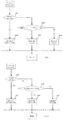
- FIG. 1B illustrates a schematic block diagram of a control system of a hybrid electric vehicle in accordance with some example embodiments.
- the engine power subsystem 20 includes an engine 3 and a dual clutch transmission 4.
- the motor power subsystem 30 includes an electric motor 5, a gear reducer 6, a power battery 7, and an inverter 8.
- the engine 3 is connected to the transmission system 10 through the gearbox 4.
- the motor 5 is connected with the transmission system 10 through the gear reducer 6.
- the power battery 7 provides power to the electric motor 5.
- the above-described hybrid electric vehicle may have a dual-mode plug-in hybrid structure where the engine 3 is a turbocharged direct injection engine configured to provide power to the vehicle.
- the transmission 4 is a dual clutch transmission configured to transmit the power provided by the engine 3.
- the power battery 7 is connected to the inverter 8 via a DC bus.
- the inverter 8 is connected with the electric motor 5 via a three-phase AC bus.
- the electric power couples with the fuel power in the transmission system 10.
- the transmission system 10 transmits the power to the wheels 2a and 2b.
- the operator can manually select work mode of the hybrid electric vehicle by EV mode selection button, HEV mode selection button, and driving mode selection button.
- FIG. 1C illustrates a block diagram of an idle start-stop control system in accordance with some example embodiments.
- the idle start-stop control system includes a power battery 7.
- the power battery 7 is connected to an ECN (Electromotor Controller, motor control device) 100 via the DC bus.
- the ECN 100 is connected to the electric motor 5 via the three-phase AC bus.
- the motor 5 is connected to the transmission system 10 via the reducer 6.
- the engine 3 is connected to the transmission system 10 via the dual-clutch transmission 4.
- the electric power couples with the fuel power in the transmission system 10.
- the transmission system 10 then transmits the power to the wheels 2a and 2b.
- BMS Battery Management System
- SCU Shift Control Unit, position controller
- ESC Electronic Stability Control, Electronic Stability Control system
- FIG. 2A illustrates a signal flow diagram of an idle start-stop control system in accordance with some example embodiments.
- the idle start-stop control system may control the engine according to status signals, such as vehicle speed signal indicative of vehicle speed that is determined by the ESC 400, shift position signal indicative of transmission shift lever position that is determined by the SCU 300, water temperature signal indicative of water temperature at engine thermostat that is determined by the ECM 500, and maximum power signal indicative of maximum allowable discharge power that is determined by the BMS 200.
- status signals are transmitted via CAN messages to the ECN 100.
- the ECN 100 then sends "engine start/stop command" to the ECM 500 based upon the above status signals as well as operating mode, work mode and power status.
- ECM 500 may enable the engine to start or stop upon receipt of the CAN messages.
- the work mode may include an electric-only mode (EV mode) and a hybrid mode (HEV mode).
- the EV mode may include electric-alone economy mode (EV-eco mode) and electric-alone sport mode (EV-s mode).
- the hybrid mode may include hybrid economy mode (HEV-eco mode) and hybrid sport mode (HEV-s mode).
- EV mode selection button may be available for an operator to manually select the EV mode.
- HEV mode selection button may be available for an operator to manually select the HEV mode.
- the driving mode selection button is available for an operator to manually switch between eco and sport mode.
- operator can manually switch between two work modes: either EV mode or HEV mode.
- the operator can also manually switch between two driving modes: either economy mode or sport mode.
- four operating modes are obtained and available for the operator's selection: EV-eco, EV-s, HEV-eco, and HEV-s.
- EV mode allows the vehicle to operate entirely on electric motor.
- HEV mode allows the electric motor to supplement the engine's power, thereby achieving better performance.
- economy mode the electric motor, engine, and battery may not deliver their respective maximum output power, thereby keeping all of them to work in economic mode.
- sport mode supports dynamic priority strategy. Accordingly, in sport mode, the electric motor, engine, and battery may deliver their respective maximum output power, thereby obtaining all energy generated by the electric motor, engine, and battery.
- FIG. 2B illustrates a signal flow diagram of a hybrid electric vehicle in accordance with some example embodiments.
- the SCU is configured to collect a shift signal indicative of shift level position as well as a operating mode signal indicative of an operating mode, i.e., EV/HEV/eco/sport.
- the shift signal and the operating mode signal are sent to the ECN for verification.
- the ECN transmits the shift signal as well as the driving mode signal to the BMS, the ECM, a TCU (Transmission Control Unit), and a display device.
- the ECN may execute a corresponding system control program based upon driving mode and send to the ECM an engine start/stop command as well as an engine target torque signal indicative of an engine target torque.
- the BMS may verify the driving mode signal upon receipt and execute an energy management program.
- the ECM may execute an engine system control program and transmit to the TCU an engine torque signal indicative of current torque value.
- the ECN may collect signals associated with throttle, brake, and vehicle speed.
- the ECN may also implement shift transmission according to the transmission shift strategy.
- the display device displays the current operating mode, one of the EV-eco, EV-s, HEV-eco, and HEV-s modes.
- control module 40 is configured to select one of EV-eco-mode, EV-s mode, HEV-eco mode, and HEV-s mode according to the driving status of the vehicle and/or the status of the power battery.
- FIG. 3 is a flow chart illustrating a control method when hybrid electric vehicle operates in EV-eco mode in accordance with some example embodiments.
- SOC electric quantity
- the control module 40 is configured to enable the vehicle to enter into HEV-eco mode.
- the vehicle when the hybrid electric vehicle operates in EV-eco mode and operator does not manually select another driving mode, the vehicle is driven by the battery-powered motor while the engine is kept off. If operator manually selects HEV mode, the hybrid electric vehicle enters into HEV-eco mode. Alternatively, if operator manually selects sport mode, the vehicle enters into EVs mode.
- the control module 40 is configured to switch the operating mode to HEV-eco mode. If the vehicle operates in EV-eco mode, in order to improve the efficiency of power to allow the vehicle to drive extended distances, the electric motor may not be allowed to produce its maximum allowable power. The acceleration performance is taken into account in this mode. The electric motor may be capable of producing its maximum allowable torque. In other words, when the hybrid electric vehicle operates in EV-eco mode, the control module 40 is configured to restrict the allowable output power of the electric motor 5.
- FIG. 4 is a flow chart illustrating a control method when a hybrid electric vehicle operates in EV-s mode in accordance with some example embodiments.
- the hybrid electric vehicle operates in EV-s mode, if it is determined that the SOC of the power battery is below the lower limit of the SOC of the power battery SOC min , e.g., 20%, or the maximum allowable discharge power of the power battery Pb is below the lower limit of the allowable discharge power of the power battery Pb min , e.g., 12KW, or the slope i exceeds upper limit of the slope i max , e.g., 15%, the control module 40 is configured to enter into HEV-s mode.
- the control module 40 is configured to enter into HEV-s mode.
- the vehicle when the hybrid electric vehicle operates in EV-s mode and the operator does not manually select another operating mode, the vehicle is driven by the electric motor-powered by the power battery while the engine is kept off.
- the operating mode When the operator manually selects HEV mode, the operating mode is switched to HEV-s mode.
- the operating mode When operator manually selects the eco mode, the operating mode is switched to EV-eco mode.
- the control module 40 is configured to control the the vehicle to switch to HEV-s mode.
- the control method prioritizes dynamic performance. Accordingly, the output power of the electric motor is not restricted.
- the control module 40 when the hybrid electric vehicle operates in EV-eco mode or EV-s mode, if receiving a mode switch request of the operator or triggering a mode switch function so as to switch between different operating modes, the control module 40 is configured to switch to a target mode in response to the request of the operator.
- the vehicle by selecting the EV mode and selecting the driving mode between economy mode and sport mode, the vehicle operates in EV-eco mode or EV-s mode. Because hybrid electric vehicles can employ a plug-in battery charging structure, the battery capacity is therefore increased. By using a high-power and high-torque electric motor, the hybrid electric vehicle can work in a more powerful manner in EV mode, thus being capable of dealing with all city road conditions and most suburban road conditions without triggering automatic mode switch function. Only when the slope exceeds the upper limit of the slope i max , e.g., 15% (the maximum slope value in EV mode), the mode is automatically switched to the HEV mode. For instance, unless the operator manually selects other work mode, the work mode is remained in HEV mode.
- the electric motor may not deliver its maximum power but may produce maximum torque. In this mode, performance of hill climbing at low speeds and high efficiency at high speeds are obtained.
- the electric motor In EV-s mode, the electric motor may produce its maximum power and maximum torque, which may provide the strongest horsepower in the EV mode.
- EV mode prioritizes dynamic performance and allows the vehicle to drive extended distances by avoiding high power consumption resulting from long time use of the battery to improve electricity usage efficiency and at the same time ensure the vehicle to operate in a good manner under one of the below conditions: the SOC of the battery is low, the maximum allowable discharge power of the battery is not sufficient, and the slope is steep. As a result, dynamic performance may not be decreased due to certain factors.
- only one mode transition is automatically executed which may avoid frequent engine start/stop, thus improving the life of the starter, reducing noise, and improving driving comfort.
- FIG. 5 is a flow chart illustrating a control method when a hybrid electric vehicle operates in HEV-eco mode in accordance with some example embodiments.
- the control module when the hybrid electric vehicle operates in HEV-eco mode, the control module is configured to receive a request to select EV-eco mode. If the control module determines that the SOC exceeds the upper limit of the electric quantity SOC max , e.g., 30% and the vehicle speed V is below the maximum speed V max , e.g., 150 km/h, the control module is configured to switch the operating mode to EV-eco mode.
- SOC max the upper limit of the electric quantity SOC max
- V max e.g. 150 km/h
- the vehicle When the hybrid electric vehicle operates in HEV-eco mode, under the conditions that the slope i is below the lower limit of the slope i min , e.g., 5%, the SOC is below the upper limit of the electric quantity SOC max , e.g., 30%, and the maximum allowable discharge power of the battery Pb is below the upper limit of the allowable discharge power of the battery Pb max , e.g., 30KW, the vehicle operates in HEV-eco mode.
- the slope i is below the lower limit of the slope i min , e.g., 5%
- the SOC is below the upper limit of the electric quantity SOC max , e.g., 30%
- the maximum allowable discharge power of the battery Pb is below the upper limit of the allowable discharge power of the battery Pb max , e.g., 30KW
- the SOC is below the lower limit of the electric quantity SOC min , e.g., 20%, or under the conditions that the slope is below the lower limit of the slope i min , e.g., 5%, and the maximum allowable discharge power of the battery Pb is below the lower limit of the maximum allowable discharge power of the battery Pb min , e.g., 12KW, the vehicle operates in the low power manner.
- the upper limit of the electric quantity SOC max is set greater than the lower limit of the electric quantity SOC min .
- the upper limit of the maximum allowable discharge power of the battery Pb max is greater than the lower limit of the maximum allowable discharge power of the battery Pb min .
- the low power manner means that the engine drives the motor to generate power quickly, thus getting the motor out of the low power manner.
- the motor is enabled to adjust the operation range of the engine to ensure economic operation of the vehicle.
- FIG. 6 is a flow chart illustrating a control method when a hybrid electric vehicle operates in EV-eco mode by economy manner in accordance with some example embodiments.
- the control module is configured to enable the hybrid electric vehicle to operate in EV mode.
- the control module is configured to control the engine to output torque according to a preset maximum torque curve and enable the electric motor to produce compensation torque.
- the control module is configured to control the engine to output torque according to a preset minimum torque curve and produce power.
- the motor control device is configured to control the engine to produce torque to meet torque requisition and supply power to the electric motor.
- the preset maximum torque curve and preset minimum torque curve are shown in FIG. 7 .
- relationship between quantity of electric charge SOC and motor power is shown in FIG. 8 .
- FIG. 9 is a flow chart illustrating a control method when a hybrid electric vehicle operates in HEV-eco mode by low power manner in accordance with some example embodiments.
- the control module When the hybrid electric vehicle is running by the low power manner and the transmission shift lever is not in park P and when the torque requisition T R exceeds the maximum torque T max permitted from the engine, such as beyond the maximum torque curve, the control module is configured to control the engine to output torque according to the maximum torque curve and enable the electric motor to produce compensation torque.
- the torque requisition T R is less than the minimum torque T min produced by the engine, such as under the minimum torque curve, the control module is configured to control the engine to output torque according to the minimum torque curve and produce power.
- the motor control device When the torque requisition T R does not exceed the maximum torque T max permitted from the engine and exceeds the minimum torque T min produced by the engine, namely, under the maximum torque curve and beyond the minimum torque curve, the motor control device is configured to control the engine to output torque to meet torque requisition and control the motor to produce power.
- the control module when the hybrid electric vehicle operates in low power manner and the transmission shift lever is in park P, the control module is configured to enable the hybrid electric vehicle to operate by idle start-stop strategy. When the hybrid electric vehicle enters to operate by idle start-stop strategy, the control module also determines whether the hybrid electric vehicle idle start-stop conditions are satisfied.
- control module determines that the hybrid electric vehicle satisfies the idle start-stop conditions, such as vehicle speed is zero, transmission shift lever is in park P, and quantity of electric charge SOC is greater than 20%, the control module is configured to shut down the engine power subsystem.
- the control module is configured to enable the hybrid electric vehicle to operate in EV mode.
- the vehicle speed exceeds 30km/h
- the engine starts to drive the vehicle.
- the vehicle is enabled to enter into EV mode when the speed is reduced to 15km/h.
- the electric motor does not produce sufficient power to drive the vehicle, the engine may start to produce power.
- the vehicle is disabled to work in EV mode at low speeds but is enabled to work by low power manner.
- the control module is configured to enable the idle start-stop function when transmission shift lever is in park P. In other words, by low power manner, when the SOC is below a certain level (for example 20%) the motor supplements the power of the engine.
- the engine works in economy manner and at the same time provides power to the motor.
- low power manner when the electric power of the vehicle is on and the transmission shift lever is not in park P, the engine is kept running. Under the conditions that the vehicle speed V is zero, the transmission shift lever is in park P, and the SOC exceeds 20%, the engine operates by idle start-stop strategy. The engine is shut off.
- low power manner the EV mode is not available for operation and the engine is running to drive the vehicle.
- the engine employs the same control method as in the economy manner,.
- the maximum torque curve and the minimum torque curve of the engine are shown in FIG. 7 . It desires to include the largest fuel economic area between the maximum torque curve and minimum torque curve.
- the electric motor supplements the engine's power to drive the load.
- the engine may produce torque in accordance with minimum engine torque curve. Extra torque produced by the engine may be used to supply power to the electric motor.
- the engine may produce the torque in accordance with maximum engine torque curve.
- the electric motor may produce torque and compensate the torque. If charge or discharge capacity is restricted by characteristics of the electric motor or the battery, the electric motor may charge or discharge the battery according to its maximum capacity. Under this condition, the operation of the engine may not be restricted by the upper and lower limits of the engine torque and may output desired torque to meet the needs of the vehicle. When the output torque value of the engine is between the maximum torque curve and minimum torque curve, the electric motor produces power.
- the torque produced by the engine does not exceed the upper limit of the torque.
- Power value and SOC value compose a function, as shown in FIG. 8 .
- the slope i does not exceed the upper limit i max , e.g., 15 %.
- the slope i exceeds the upper limit i max , i.e., 15%, the engine is started to meet the hill-climbing performance. No limitation is imposed on the upper limit and the lower limit of the power produced by the engine and the electric motor. Until the slope is less than the lower limit of the slope i min , e.g., 5%, the original operating mode, such as HEV-eco mode, is executed.
- the structure of the control system comprises an engine and an electric motor.
- the engine and the electric motor are connected in parallel through a dual-clutch transmission.
- the traditional transmission system may comprise engines, MG1 and MG2 connected in series-parallel through a planetary gear set.
- the control method depends on vehicle speed and the battery charge or discharge power requisition, and power requisition. Vehicle speed that determines transitions between different operating modes is relatively low. By the low power manner, when the quantity of electric charge SOC is less than 20%, the engine may operate by low power manner. In contrast, in the traditional transmission system, the lower limit of the quantity of electric charge SOC that determines whether to operate by low power manner is 45% or less.
- the control system operates by idle start-stop strategy, so long as the vehicle speed is zero, the transmission shift lever is in park P, and the SOC exceeds 20%, the engine is shut off. In contrast, in the traditional transmission system, water temperature of the engine is also considered to determine whether to shut off the engine.
- the SOC in the traditional transmission system is set at a relatively high value.
- whether the control system of the hybrid electric vehicle operates by either economy manner or the low power manner depends on various factors, rather than keeping the amount of electric charge balance.
- the SOC enters into equilibrium state after transmission system is running for a short period of time.
- Different configuration of the engine and the electric motor results in different control methods.
- rotation speed of the engine is adjusted by adjusting the rotation speed of MG1.
- the idle speed of the engine is up to 1200rpm. In embodiments of the present invention, the idle speed of the engine is about 800rpm.
- the control system is configured to control six shift levers of the double-clutch. Shift operation is relatively simple.
- either all of the power produced by the engine is used to drive the load or part of the power produced by the engine is used to drive the load and part of the power produced by the engine supplies to the battery.
- part of the power produced by engine is provided to MG1 to generate power which is then provided to MG2 to drive the vehicle.
- both the power required to start or stop the engine and the vehicle speed shifted between different operating modes are set relatively low, which result in early and frequent ignition. More use of the engine increases fuel consumption and emissions in urban conditions.
- the control system of the hybrid electric vehicle has a strong driving capacity in EV mode which can meet the needs of vast majority of drivers. Threshold values that determine whether the engine starts or stops are set relatively high. An engine may be used less in driving, which may reduce fuel consumption and emissions in urban conditions.
- An operation of the user on throttle may reflect more power demand, which may avoid determining the power requisition of the entire vehicle, thereby reducing frequent start/stop of the engine, extending life of the motor, reducing noise, and improving comfort.
- acceleration at wide-open throttle may be reduced.
- the movement of the vehicle may result in less impact, thus improving driving safety and comfort.
- the SOC and water temperature of the engine are taken into account to determine whether to start or stop the engine. Because these factors are not controlled by an operator, it is hard to summarize operation rules. Small battery capacity may result in relatively large SOC value, which may cause the engine idle when the vehicle stops at stoplights despite the transmission shift lever is in park P.
- the idle speed of the engine may be up to 1200rpm. It may result in louder engine noise and higher fuel consumption than ordinary fuel vehicles.
- the control system may turn off the engine when the transmission shift lever is in park P, which may help operators to summarize operation rules, thus reducing the noise when vehicle stops and increasing comfort during parking.
- the idle speed of the engine in embodiments of the present invention is similar to traditional vehicles powered by internal combustion engine. In addition, no balancing is made on the quantity of electric charge in the control system of the present invention. The vehicle will automatically switch between economy strategy and low power strategy based on the actual working conditions which may highlight electric motor's capability of adjusting the operating area in which the engine operates. This may further help to reduce fuel consumption and emissions.
- structure of the dual clutch transmission employed by the transmission system is simple which may improve transmission match rate, thereby reducing the cost. Due to employment of the series-parallel configuration, the control strategy employed by the engine and the control strategy employed by the motor may work in more efficient way. As a result, power conversion efficiency is improved. Finally, in embodiments of the present invention, the power generation strategy is to dynamically associate the engine with the SOC so that the vehicle can maintain a high quantity of electric charge when the vehicle is driven in normal status with medium or low load.
- the control module when the hybrid electric vehicle operates in HEV-s mode, upon receipt of a signal indicative of switching the operating mode to EV-s mode, under conditions that if it is determined the SOC exceeds the upper limit of the electric quantity SOC max , e.g., 30%, and the current vehicle speed V is below the maximum speed V up , e.g.,150km/h, the control module is configured to switch the operating mode to EV-s mode.
- the control module when the hybrid electric vehicle operates in HEV-s mode, if the current transmission shift lever is in park P, the control module is configured to operate by idle start-stop strategy. Otherwise, if the current transmission shift lever is not in park P, when the torque requisition T R exceeds a peak torque (maximum torque T max ) of the engine, the control module is configured to control the engine to produce torque in accordance with the peak torque and enable the motor to compensate the torque. When the torque requisition T R is below the peak engine torque T max , the control module is configured to control the engine to produce torque to meet vehicle requisition and enable the motor to generate power.
- FIG. 10 is a flow chart illustrating a control method when the hybrid electric vehicle operates in HEV-s mode in accordance with some example embodiments.
- the control module When the hybrid electric vehicle operates in HEV-s mode, when operator manually selects EV mode, only under conditions that the SOC exceeds the upper limit of the electric quantity SOC max , e.g., 30%, and the vehicle speed V is below the maximum speed V up , e.g., 150 km/h, the control module is configured to select the EV-s mode. When no mode selection is manually executed, the operating mode remains in HEV-s mode. Operation strategy in HEV-s mode is similar to that in HEV-eco mode with employment of the low power manner. No restriction is imposed on upper and lower limit of the power produced by the electric motor and the torque produced by the engine. The electric motor can produce its maximum power. Engine can produce its maximum torque. The best dynamic performance can be obtained by idle start-stop strategy.
- double-clutch transmission transfers power produced by engine and executes the transmission shift operation.
- each mode is associated with a particular transmission shift strategy.
- Control strategy implemented by HEV-eco mode is to reduce fuel consumption.
- transmission shift strategy implemented in HEV-eco mode is to enable the engine to work more efficiently and each transmission shift is executed earlier than predicted.
- the rotation speed of engine is usually within range of 1500 ⁇ 2000rpm.
- control strategy implemented by HEV-s mode is to improve dynamic performance.
- the transmission shift strategy implemented by HEV-s mode is to transfer as large as possible torque produced by the engine to the wheels thus obtaining better driving performance.
- the transmission shift is executed later than predicted. When rapid acceleration is made at fully open throttle, transmission shift is executed using the largest torque produced by the engine regardless of the current gear to increase acceleration performance.
- FIGs. 11-14 illustrates methods of controlling idle start-stop function in accordance with some example embodiments.
- whether to operate by idle start-stop strategy is determined by conditions including power mode, operating mode or work mode, slope of the road, and vehicle speed.
- the idle start-stop strategy is enabled.
- the vehicle may operate by idle start-stop strategy accordingly.
- the idle start-stop strategy is disabled.
- the idle start-stop function is disabled, even all idle start-stop conditions are met, the engine will not execute idle start-stop strategy.
- the idle start-stop conditions are determined by fault detection result of both the high pressure system and the communication system, the enablement status of idle start-stop strategy, transmission gearshift position, the maximum allowable discharge power, and the water temperature at engine thermostat.
- the idle start-stop strategy is enabled, if the above conditions are met, the engine is shut off.
- whether to operate by idle start-stop strategy is determined by conditions including fault detection result of high-pressure system and communication system, transmission shift lever position, maximum allowable discharge power by battery, and water temperature at engine thermostat.
- the idle start-stop strategy is enabled, if any above condition is met, the engine will execute idle start-stop strategy.
- the parallel configuration employed by the engine power subsystem and the motor power subsystem improves the energy efficiency. Since the parallel configuration is simpler than series-parallel configuration, complex compatibility with ECVT is avoided. Smooth operation between different operating modes and economy performance are improved without sacrificing dynamic performance.
- the idle start-stop strategy may reduce the fuel emissions and frequent starts and stops which may help to extend the life of the motor.
- the engine idle start-stop strategy is disabled when power supply is abnormal to ensure the power supply to the electrical equipment.
- the upper limit of the power produced by the battery when the hybrid electric vehicle operates in EV-eco mode, is less than a first preset power.
- the upper limit of the power produced by the battery is less than a second preset power.
- the second preset power is greater than the first preset power.
- both the upper limits of the power produced by the battery and the engine are less than the first preset power.
- the upper limit of the torque produced by the engine is less than a preset torque.
- the hybrid electric vehicle operates in the HEV-s mode the upper limit of the power produced by the battery is less than the second preset power.
- the engine is allowed to produce power in accordance with the maximum power curve.
- the engine is allowed to produce torque in accordance with the maximum torque curve.
- the first preset power may be 70KW.
- the second preset power may be 110KW.
- the preset torque value may be 185N • M.
- the EV-eco mode means that when hybrid electric vehicle operates in EV mode, the upper limit of the power produced by the battery is less than the upper limit of the power in economy mode, such as 70KW. In this mode, the battery may work in the most fuel economic area.
- the EV-s mode means that the power produced by the battery is less than the upper limit of the power produced in sport mode, e.g., 110KW.
- the upper limit of the power produced by the battery is less than the upper limit of the power produced in the economy mode, e.g., 70KW.
- the upper limit of the torque produced by the engine is less than the upper limit torque produced in the economy mode, e.g., 185N • M.
- the engine and battery both operate in the most fuel economic area.
- the upper limit of the power produced by the battery is less than the upper limit of the power produced by the battery in sport mode, e.g., 110KW.
- the engine is allowed to produce the power in accordance with the maximum power curve.
- the engine is allowed to produce torque in accordance with the maximum torque curve.
- the most fuel economic area in EV mode means that with the increase of the power discharged by the battery, battery efficiency is decreased. As a result, while dynamic performance (operational performance and acceleration performance) is ensured, the battery is configured to work at lower power discharge rate.
- the most fuel economic area are determined by torque and rotation speed of the engine. As shown in FIG. 7 , the x-axis indicates the engine rotation speed. The y-axis represents the engine torque. FIG. 7 shows that at different rotation speeds the most economic operating area can be achieved with an appropriate torque chosen. If the engine torque is too high, engine torque is decreased and the torque is compensated by the motor. If the engine torque is too low, the engine torque is increased. The vehicle does not need to use the increased engine torque to drive. The increased torque can be stored and reused by the motor to produce power.
- the upper limit of the power in economy manner means the upper limit of the power produced by the engine or the motor while they work within the fuel economic area.
- the upper limit of the power of the battery, motor, and the engine are set in accordance with the maximum power that can be produced.
- the engine produces torque or power in accordance with the maximum torque or the maximum power.
- the battery produces power in accordance with the maximum power. In this manner, the power system delivers maximum power or torque to the vehicle.
- the hybrid electric vehicle further comprises a fuel-only mode.
- the fuel-only mode is an abnormal operating mode.
- the parallel configuration employed by the engine power subsystem and the motor power subsystem improves the energy efficiency. Since the parallel configuration is simpler than series-parallel configuration, complex operation employed in series-parallel configuration to switch between modes is avoided. Smooth operation between different operating modes and economy performance are improved without sacrificing dynamic performance.
- the idle start-stop strategy may reduce the fuel emissions and frequent starts and stops which may help to extend the life of the motor, reduce noise and improve driving comfort.
- the power requisition is set at relatively high. Engine may be used less in driving which may reduce fuel consumption and emissions in urban conditions.
- FIGs. 3-14 further describe control methods according to the present invention.
- the hybrid electric vehicle comprises a transmission system, an engine power subsystem and motor power subsystem.
- the transmission system is coupled with the engine power subsystem and the motor power subsystem, respectively.
- FIG. 11 is a flowchart illustrating a method of controlling a hybrid electric vehicle in accordance with some example embodiments. As shown in FIG. 11 , the hybrid electric vehicle control method comprises the following steps:
- the engine power subsystem and the motor power subsystem are configured to enable the hybrid electric vehicle to enter into an appropriate operating mode.
- the driving mode includes HEV-eco mode and HEV-s mode.
- the work mode includes EV mode and HEV mode, and the driving mode may include economy mode and sport mode,
- the EV mode includes two operating modes such as EV-eco mode and EV-s mode
- the HEV mode includes two operating modes such as HEV-eco mode and HEV-s mode.
- step S2 when the hybrid electric vehicle operates in HEV-eco mode and low power mode, or when the hybrid electric vehicle operates in HEV-s mode, the method determines whether the vehicle speed is zero.
- step S3 if it is determined that the vehicle speed is zero at step S2, the hybrid electric vehicle operates by idle start-stop strategy.
- control method when the hybrid electric vehicle operates in EV-eco mode, the control method further includes the following steps of:
- a signal indicative of a manual operation of selecting an operating mode is received by the motor control device ("manual selection operating signal").
- the manual selection operating signal can be in response to a selection of HEV mode, or sport mode. If no manual operation of selecting operating mode is executed, no such a signal is generated.
- the control system determines whether a manual operation is executed. If the method determines that a manual operation is executed, the method proceeds to step S102. Otherwise the method proceeds to step S103.
- the control system is configured to enter into an operating mode in response to the manual selection operation signal and execute a control strategy associated with that manual selection operation.
- the control module upon receipt of the manual selection operation signal, the control module is configured to enter into a target operating mode in response to the manual selection of the user.
- step S103 no manual operation of selecting operating mode is executed.
- the vehicle remains in the current operating mode.
- the values of the quantity of electric charge SOC, maximum allowable discharge power of the battery Pb, and the slope i are compared with respective predetermined values.
- the lower limit of the electric quantity SOC min is 20%.
- the lower limit of the maximum allowable discharge power of the battery Pb min is 12KW.
- the upper limit of the slope i max is 15%.
- the operating mode is automatically switched to HEV-eco mode.
- the SOC is below the lower limit of the electric quantity SOC min 20%, or the maximum allowable discharge power of the battery Pb is below the lower limit of the maximum allowable discharge power of the battery Pb min , e.g. 12KW, or the slope exceeds the upper limit of the slope i max 15%.
- the operating mode is automatically switched to the HEV-eco mode.
- step S105 if none of the conditions set at step S103 is met, the vehicle remains in EV-eco mode.
- EV-eco mode when no manual or automatic operation of selecting an operating mode is performed, the motor acts as a single power source to drive the vehicle.
- This mode prioritizes dynamic performance and electricity savings by avoiding high power consumption resulting from long time use of the battery to improve electricity usage efficiency.
- the maximum power produced by the motor is limited to PM max , e.g., 70KW.
- This mode is also designed to meet hill-climbing performance without limiting the maximum torque produced by the motor. In other words, when the hybrid electric vehicle is in EV-eco mode, the hybrid electric vehicle operates with restriction of the power.
- the operating mode may be automatically switched to HEV-eco mode when the SOC, the maximum allowable discharge power, and the slope value are amount to some predetermined values which may enable the vehicle to operate in normal status without having negative impact on dynamic performance.
- the control method prioritizes dynamic performance and high efficiency thus achieving extended life of the motor, lower operating costs, and less emissions.
- control method when the hybrid electric vehicle operates in EV-s mode the control method includes following steps:
- a manual selection operating signal indicative of a manual operation of selecting operating mode is received by the control system.
- the manual selection operating signal can be in response to a selection of HEV mode, or sport mode. If no manual operation of selecting operating mode is performed, no such a signal is generated.
- the control system determines whether a manual operation is performed. If the control system determines that a manual operation is performed, the method proceeds to step S202. Otherwise the method proceeds to step S203.
- the control system is configured to enter into an operating mode in response to the manual selection operation signal and execute a control strategy associated with the manual selection operation.
- the control module upon receipt of the manual selection operation signal, the control module is configured to enter into the target operating mode in response to user's manual selection operation.
- step S203 no manual operation of selecting operating mode is performed.
- the vehicle remains in the current operating mode.
- the SOC values, the maximum allowable discharge power of the battery Pb, and the slope i are compared with respective predetermined values.
- the lower limit of the electric quantity SOC min is 20%.
- the lower limit of the maximum allowable discharge power of the battery Pb min is 12KW.
- the upper limit of the slope i max is 15%.
- the control method further determines if SOC ⁇ SOC min , Pb ⁇ Pb min , and i max ⁇ i.
- the operating mode is automatically switched to the HEV-s mode.
- the SOC is below the lower limit of the electric quantity SOC min , e.g. 20%, or the lower limit of the maximum allowable discharge power of the battery Pb is below the lower limit of the maximum allowable discharge power of the battery Pb min 12KW, or the slope exceeds the upper limit of the slope i max 15%.
- the operating mode is automatically switched to the HEV-s mode.
- step S205 if none of the conditions set at step S203 is met, the vehicle remains in EV-s mode.
- the motor acts as a single power source to drive the vehicle.
- this mode no limitation is imposed on the maximum torque and the power that are produced by the engine. Maximum power of the motor is achieved to meet the dynamic demand of the operator, for example, acceleration and hill climbing at high speeds.
- the operating mode may be automatically switched to HEV-s mode when the SOC, the maximum allowable discharge power, and the slope value are amount to some predetermined values which may enable the vehicle to operate in normal status without having negative impact on dynamic performance.
- the control method is suitable for operating in EV mode without sacrificing dynamic performance.
- the operating mode is more flexible. The operator can obtain better driving experience.
- control method comprises following steps:
- step S301 a manual selection operating signal indicative of a manual operation of selecting operating mode is received by the control system. If it determines that a manual operation of selecting EV mode is performed, the method proceeds to step S302. Otherwise, the method proceeds to step S306.
- step S302 the SOC is compared with a predetermined upper limit of the electric quantity SOC max 20%. If it is determined that the SOC exceeds the upper limit of the electric quantity SOC max , the method proceeds to step S303. Otherwise, the method proceeds to step S305.
- step S303 the current vehicle speed is compared with the maximum speed V up 150km / h. In an instance in which the vehicle speed v is below V up , the process proceeds to step S304. Otherwise, the process proceeds Step S305.
- step S304 the vehicle enters into EV-eco mode and performs the corresponding control strategy.
- the control module is configured to enable the vehicle to enter into EV-eco mode.
- step S305 the vehicle remains in HEV-eco mode.
- step S301 When no manual operation of selecting EV mode is performed at step S301, the method proceeds to step S306. At step S306, the method determines that whether manual operation of selecting sport mode has been performed. If a manual operation of selecting sport mode has been performed, the method proceeds to step S307. Otherwise, the process proceeds to step S308.
- control system is configured to enable the hybrid electric vehicle to enter HEV-s mode and perform a corresponding control strategy.
- the operating mode remains in HEV-eco mode.
- the control system may receive a signal indicative of the gradient of slope.
- the value of the current slope i is compared with the lower limit of the slope i min (e.g., 5%) and the upper limit of the slope i max (e.g., 15%) at following steps.
- step S309 the slope of the road is compared with lower limit of the slope i min . If it is determined that the slope i ⁇ i min , the method proceeds to the next step S310.
- the SOC is compared with upper limit of the electric quantity SOC max (e.g., 30%) and lower limit of the electric quantity SOC min (e.g., 20%).
- the maximum allowable discharge power of the battery Pb is compared with the upper limit of the power of the battery Pb max (e.g., 30KW) and lower limit of the power of the battery Pb min (e.g., 12KW).
- step S311 the SOC is compared with the upper limit of the quantity of electric charge SOC max .
- Pb is compared with upper limit of the maximum allowable discharge power of the battery Pb max . If the method determines SOC max ⁇ SOC and Pb max ⁇ Pb, the method proceeds to step S312. Otherwise, the method proceeds to step S313.
- the hybrid electric vehicle employs economy strategy in operation.
- the control module is configured to enable the hybrid electric vehicle to operate in economy manner.
- step S313 if the method determines that SOC max > SOC > SOC min and Pb max ⁇ Pb, or SOC max ⁇ SOC and Pb max > Pb > Pb min , the method proceeds to step S314. Otherwise, the method proceeds to step S315 to further compare the SOC with lower limit of the electric quantity SOC min and maximum allowable discharge power Pb with lower limit of the maximum allowable discharge power Pb min . In other words, when the SOC and the maximum allowable discharge power Pb do not meet the conditions set at step S311 and S313, i.e., SOC ⁇ SOC min , Pb ⁇ Pb min , the method proceeds to step S315.
- step S314 the control strategy that is employed in previous operation is remained to be used in current operation.
- the hybrid electric vehicle employed economy manner in previous operation the hybrid electric vehicle may continue to employ economy manner in current operation.
- the hybrid electric vehicle employed low power manner in previous operation the hybrid electric vehicle may continue to employ low power manner in current operation.
- step S315 if the method determined that SOC ⁇ SOC min , Pb ⁇ Pb min , the method proceeds to step S316.
- the hybrid electric vehicles employs low power manner in operation.
- the control module is configured to enable the hybrid electric vehicle to operate in low power manner.
- the upper limit of the electric quantity is greater than the lower limit of the electric quantity.
- the upper limit of the power is greater than the lower limit of the power.
- step S317 it further compares the slope i with the lower limit of the slope i min and the upper limit of the slope i max . If it is determined that i max > i > i min , the method proceeds to step S318. Otherwise, the method proceeds to step S319.
- step S318 the control strategy that is employed in previous operation remains to be used in current operation.
- the control strategy is the same as i ⁇ i min or i max ⁇ i, which has been employed in previous operation.
- step S319 the slope i is further compared with i max . If it is determined that i min ⁇ i, the method proceeds to step S320.
- step S320 the vehicle is disabled to work in EV mode at low speeds.
- Engine alone is used to drive the vehicle. No limitation is imposed on maximum output of the engine and the motor.
- low power manner means that the engine enables the motor to generate power quickly, thereby making the motor out of low-power state. In this manner, the motor is enabled to keep the engine work in fuel economic area.
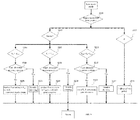
- FIG. 6 is a flow chart illustrating when the hybrid electric vehicle operates in economy mode, the control method comprises following steps:
- step S401 signal indicative of the vehicle speed is received.
- the vehicle speed is compared with upper limit of vehicle speed V max (e.g., 30km / h) and lower limit of vehicle speed V min (e.g., 15km / h).
- step S402 vehicle speed is compared with upper limit of vehicle speed V max . If it is determined that V min ⁇ V, the method proceeds to step S403. Otherwise, the method proceeds to step S415.
- step S403 if the method determines that the vehicle torque requisition T R exceeds the maximum torque curve, as shown in FIG. 7 , the method proceeds to step S404. Otherwise, the method proceeds to step S407.
- step S404 it is determined that whether fault has been detected in the power system. If fault has been detected in the power system, the method proceeds to step S406. Otherwise, the method proceeds to step S405.
- the engine may produce torque according to the maximum torque curve.
- the electric motor may compensate the torque.
- the control module enables the engine to produce torque in accordance with the maximum torque curve and enables the motor to supplement the torque.
- step S406 the fault has been detected in power system. Troubleshooting is performed to identify the fault.
- step S407 if the method determines that the torque requisition T R is less than the minimum torque T min permitted from the engine, such as under the minimum torque curveas shown in FIG. 7 , the method proceeds to step S408. Otherwise, the method proceeds to step S411.
- step S408 the method determines whether fault has been detected in the power system, the method proceeds to step S410. Otherwise, the method proceeds to step S409.
- step S409 no fault has been detected in the power system which is determined at step S408.
- the engine may produce torque according to the minimum torque curve. Extra torque produced by the engine may be used to supply power to the electric motor. Electric motor generates power.
- the control module enables the engine to produce the torque in accordance with the minimum torque curve and supply power to the electric motor.
- step S410 when fault has been detected in the power system, troubleshooting procedure is performed to identify fault of the power system.
- step S411 when the torque requisition T R does not exceed the maximum torque T max permitted from the engine and exceeds the minimum torque T min produced by the engine, namely, under the preset maximum engine torque curve and beyond the preset minimum engine torque curve, as shown in FIG. 7 , the method proceeds to step S412.
- step S412 is the method determines that if fault has been detected in the power system. If yes, the method proceeds to step S414. If no fault has been detected in the power system, the method proceeds to step S413.
- step S413 when the engine meets the torque requisition T R of the vehicle, extra torque generates power.
- the control module enables the engine to produce torque in accordance with minimum torque curve and supply power to the electric motor.
- the power generation strategy of the engine is in compliance with the relationship between the SOC as shown in FIG. 8 .
- the power generation strategy also meets two conditions: the power supplied to the electric motor is not greater than T max and the torque produced by the engine does not exceed maximum torque T max permitted from the engine, such as beyond the vehicle maximum engine torque curve. If any of the above two conditions is not met, limitation is imposed on the torque supplied to the electric motor.
- step S41 if fault has been detected in power system, troubleshooting is performed.
- step S415 the method further compares the vehicle speed with the upper limit of vehicle speed V max and the lower limit of vehicle speed V min . If the method determines that V max > V > V min , the method proceeds to step S416. Otherwise, the method proceeds to step S419.
- step S416 the method determines if fault has occurred in the power system. If fault has been detected, the method proceeds to step S418. If no fault has been detected, the method proceeds to step S417.
- control strategy that is employed in previous operation remains to be used in current operation at step S417.
- motor is the single source to drive the vehicle in previous operation, i.e., EV mode
- the drive mode remains in EV mode in the current operation. If the motor supplements the engine to drive or generate power, the motor works in the same manner in current operation.
- step S4108 if fault has been detected in power system, troubleshooting procedure is performed to identify fault.
- step S419 the vehicle speed is compared with predetermined lower limit of vehicle speed V min . If the method determines that V ⁇ V min , the method proceeds to step S420.
- step S420 if fault has been detected in the power system, the method proceeds to step S422. Otherwise, the method proceeds to step S421.
- step S421 if no fault has been detected in the power system, the vehicle operates in EV mode.
- the engine turns off. In other words, when the hybrid electric vehicle operates in economy mode. If the vehicle speed is below the lower limit of the vehicle speed, e.g., 15km / h, the vehicle operates in EV mode.
- the method when the hybrid electric vehicle operates in low power manner, the method includes following steps:
- step S501 a signal indicative of the current transmission shift lever position is received.
- step S502 if the method determines that the transmission shift lever is not in park P, the method proceeds to step S503.
- step S503 the torque requisition T R of the vehicle is compared with upper limit of the torque and lower limit of the torque. If the method determines that the torque requisition T R exceeds the maximum torque T max permitted from the engine, such as beyond the vehicle maximum engine torque curve as shown in FIG. 7 , the method proceeds to step S504. Otherwise, the method proceeds to step S507.
- step S504 if fault has been detected in the power system, the method proceeds to step S506. If no fault has been detected in the power system, the method proceeds to step S505.
- the engine may produce torque in accordance with maximum torque curve.
- the electric motor may supplement the torque.
- the control module enables the engine to produce torque in accordance with maximum torque curve and enables the motor to supplement the torque.
- step S506 if fault has been detected in the power system, troubleshooting procedure is performed to identify the fault.
- step S507 the torque requisition T R of the vehicle is compared with upper limit of the torque and lower limit of the torque. If the method determines that the torque requisition T R is less than the minimum torque T min permitted from the engine, such as under the minimum torque curve, as shown in FIG. 7 , the method proceeds to step S508. Otherwise, the method proceeds to step S511.
- step S508 if fault has been detected in the power system, the method proceeds to step S510. Otherwise, the method proceeds to step S509.
- the engine may produce torque in accordance with minimum torque curve. Extra torque produced by the engine may be used to supply power to the electric motor.
- the control module enables the engine to produce torque in accordance with minimum torque curve and supply power to the electric motor.
- step S510 if fault has been detected in the power system, troubleshooting procedure is performed to identify the fault.
- step S511 when the torque requisition T R does not exceed the maximum torque T max permitted from the engine and exceeds the minimum torque T min produced by the engine, namely, under the preset maximum engine torque curve and beyond the preset minimum engine torque curve, as shown in FIG. 7 , the process proceeds to step S512.
- step S512 if fault has been detected in the power system, the method proceeds to step S514. Otherwise, the method proceeds to step S513.
- step S513 when the engine meets the torque requisition T R of the vehicle, extra torque may be supplied to the electric motor.
- the control module enables the engine to produce torque in accordance with torque requisition T R and supply power to the electric motor.
- the power generation strategy of the engine is in compliance with the relationship between the power and the SOC as shown in FIG. 8 .
- the power generation strategy also meets two conditions: the power supplied to the electric motor is not greater than T max and the torque produced by the engine does not exceed maximum torque T max permitted by the engine, such as beyond the vehicle maximum engine torque curve. If any of the above two conditions is not met, limitation is imposed on the torque supplied to the electric motor.
- step S51 if fault has been detected in the power system, troubleshooting procedure is performed to identify the fault.
- step S516 if the method determines that the transmission shift lever is park P, the method proceeds to step S516.
- idle start-stop strategy is executed.
- the control module when hybrid electric vehicle operates in low power mode and transmission is in park P, the control module is configured to enable the hybrid electric vehicle to operate by idle start-stop strategy.
- the control module also determines whether the hybrid electric vehicle idle start-stop conditions are satisfied.
- the control module determines that the hybrid electric vehicle satisfies the idle start-stop conditions, such as vehicle speed is zero, transmission is in park P, and the SOC is not less than 20%, the control module is configured to shut down the engine power subsystem.
- the electric motor supplements the power of the engine to drive the load and improve fuel efficiency.
- vehicle operates in economy mode the engine operates in the fuel economic area, the engine charges battery. The lower the electric charge, the higher the charge efficiency.
- the maximum power produced by the electric motor is set to be less than PM max to avoid high power consumption resulting from long time use of the battery, thereby keep the electric charge at a relatively high level. In this manner, the motor is enabled to keep the engine work in fuel economic area, thereby reducing fuel consumption and improving economy and emission.
- the load is large, the engine may produce the torque in accordance with maximum engine torque curve.
- the electric motor may supplement the torque. Dynamic performance is enhanced in comparison with the EV mode. When user desires to drive long distance with minimum fuel consumption, user can select the HEV-eco mode.
- control method when the hybrid electric vehicle operates in HEV-s mode, the control method comprises following steps:
- step S606 the method further determines that whether manual operation of selecting the economy mode is performed. If a manual operation of selecting the economy mode is performed, the method proceeds to step S607. Otherwise, the process proceeds to step S608.
- step S607 if the method determines that a manual operation of selecting the economy mode is performed at step S606, the control system is configured to enable the hybrid electric vehicle to enter into HEV-eco mode and execute a corresponding control strategy.
- step S608 if the method determines that no manual operation of selecting the economy mode is performed at step S606, the vehicle remains the previous operating mode.
- the control system may receive a signal indicative of transmission shift lever position.
- step S609 upon receipt of the signal indicative of transmission shift lever position, the method further determines if the transmission shift lever is in park P. If the method determines that the transmission shift lever is in park P, the method proceeds to step S610.
- idle start-stop strategy is executed.
- the control module is configured to enable the vehicle to operate by idle start-stop strategy.
- step S611 if the method determines that the transmission shift lever is not in park P, the method proceeds to step S612.
- step S612 the vehicle torque requisition T R is compared with peak torque, i.e., maximum torque T max . If the torque requisition T R exceeds the preset peak torque T max , the method proceeds to step S613. Otherwise, the method proceeds to step S614.
- the engine may produce maximum torque.
- the electric motor may supplement the torque. If charge or discharge capacity of the battery is restricted by characteristics of the electric motor or the battery, the electric motor and battery may drive the vehicle using maximum capabilities. In other words, when the hybrid electric vehicle operates in HEV-s mode, if the transmission shift lever is not in park P and the vehicle torque requisition T R exceeds the maximum torque T max , the control system is configured to enable the engine to produce its maximum torque T max and the motor to supplement the torque.
- step S614 when the engine meets the torque requisition of the vehicle, extra torque may be supplied to the electric motor.
- the control module enables the engine to produce torque in accordance with torque requisition and supply power to the electric motor.
- the power generation strategy of the engine is in compliance with the relationship between the power and the SOC as shown in FIG. 8 .
- the power generation strategy also meets two conditions: the power supplied to the electric motor is below maximum torque T max and the torque produced by the engine does not exceed the maximum torque T max permitted from the engine, such as beyond the vehicle maximum engine torque curve. If any of the above two conditions is not met, limitation is imposed on the torque supplied to the electric motor.
- HEV-s mode when the transmission shift lever is not in park P and the engine is on. When the transmission shift lever is in park P and conditions of idle start-stop strategy are met, the engine turns off. In HEV-s mode, no limitation is imposed on the maximum torque and maximum power that are produced by the motor and the engine respectively, thereby achieving maximum drive capability and the best dynamic performance among four modes. In this mode, engine keeps running. Accordingly, either engine and motor drive the vehicle together or engine acts as a single source to drive the vehicle and supplies power to motor (when quantity of electric charge SOC value is below a certain level). Fuel consumption is increased with sacrificing economy performance.
- the HEV-s mode is suitable for user who desires dynamic performance and acceleration performance.
- EV-eco EV-s
- HEV-eco HEV-s
- multiple operating modes available for user's selection can meet drive demand under different road conditions, such as electric-only in city and dynamic performance in country.
- the parallel configuration employed by the engine power subsystem and the motor power subsystem improves the energy efficiency. Since the parallel configuration is simpler than series-parallel configuration, complex operation employed in series-parallel configuration to switch between modes is avoided. Smooth operation between different operating modes and economy performance are improved without sacrificing dynamic performance.
- the operating area of engine is optimized to make the engine operate in high efficiency area.
- the power generation is optimized to keep quantity of electric charge SOC at high level, thereby reducing fuel consumption and omission.
- this mode prioritizes dynamic performance and allows the vehicle to drive extended distances.
- High power consumption resulting from long time use of the battery is avoided to improve electricity usage efficiency. Frequent starts and stops is avoided which may help to extend the life of the motor, reduce noise, and improve driving comfort.
- FIG. 12 is a flowchart illustrating a method of determining how to control execution of idle start-stop strategy in accordance with some example embodiments. The method comprises following steps:
- step S1201 the method determines whether vehicle's electric power is on. If yes, the method proceeds to step S1202. If no, the method proceeds to step S1205.
- Determining whether vehicle's electric power is on may ensure no fault has occurred in the high pressure system.
- the engine can be enabled to start and stop if no fault has been detected.
- step S1202 the method determines that if the operating mode is HEV-s mode or HEV-eco mode by low-power strategy. If yes, the method proceeds to step S1203. If no, the method proceeds to step S1205.
- the engine When hybrid electric vehicle operates in HEV-s mode or HEV-eco mode with employment of low power strategy, the engine is running.
- the method may enable the engine to start, stop or idle.
- the engine and the motor's operating manner may be determined by economy strategy or low power strategy according to the quantity of electric charge of the quantity of electric charge SOC and the maximum allowable discharge power Pb.
- HEV-eco mode by employing economy strategy, the vehicle is driven in EV mode at low speeds. When the vehicle speed is exceeds the upper limit of the vehicle speed, the motor supplements the engine's power until the vehicle speed drops below the lower limit of the vehicle speed with the motor acting as the single source.
- HEV-eco mode the vehicle is disabled to work in EV mode at low speeds.
- Idle start-stop function is enabled in this mode.
- HEV-s mode engine keeps running. Even the vehicle speed below a certain value, the operating mode may not be switched to EV mode.
- HEV-eco mode with economy strategy when vehicle stops, engine is shut off.
- the idle start-stop function is disabled.
- HEV-eco mode with low power strategy when vehicle stops, the engine keeps running.
- the idle start-stop function is enabled.
- HEV-s mode the engine keeps running regardless.
- the idle start-stop function is enabled.
- other operating modes when vehicle stops, engine is shut off. The idle start-stop function is disabled.
- step S1203 the method determines if the vehicle speed is zero. If yes, the method proceeds to step S1204. If no, the method proceeds to step S1205.
- step S1204 when ECN determines that all of conditions at steps S1201 ⁇ S1203 are met, the idle start-stop function is enabled.
- the control system enables the hybrid electric vehicle to operate by idle start-stop strategy.
- step S1205 when ECN determines that any of the condition at steps S1201 ⁇ S1203 is not satisfied, the idle start-stop function is disabled.
- FIG. 13 is a flowchart illustrating a method of determining when to shut down engine when hybrid electric vehicle operate by idle start-stop strategy and engine is running in accordance with some example embodiments.
- the control method comprises the following steps:
- Occurrence of the fault in high pressure system may cause the motor to stop to produce torque or cause the battery stop to supply power.
- the vehicle operates on engine only to ensure power supply to the vehicle. So it desires to determine if fault has occurred in the high-pressure system. When fault has been detected in the high pressure system, the engine is not allowed to operate by idle start-stop strategy.
- step S1303 the method determines whether the motor control device communicates well with other modules when idle start-stop function is enabled. If the communication between modules works well, the method proceeds to step S1304. If the communication between modules does not work well, the method proceeds to step S1308.
- step S1304 the method determines whether the transmission shift lever is in park P. If the transmission shift lever is in park P, the method proceeds to step S1305. If the transmission shift lever is not in park P, the method proceeds to step S1308.
- the method determine if the maximum allowable discharge power of the battery Pb exceeds upper limit of the allowable discharge power of the battery Pb max . If the maximum allowable discharge power of the battery Pb exceeds upper limit of the maximum allowable discharge power of the battery Pb max , the method proceeds to step S1306. If the maximum allowable discharge power of the battery Pb below the upper limit of the maximum allowable discharge power of the battery Pb max , the method proceeds to step S1308.
- the battery can meet motor's minimum torque requisition by determining the maximum allowable discharge power.
- step S1306 the method determines that if water temperature at engine thermostat Temp exceeds upper limit of temperature Tempmax. If water temperature at engine thermostat Temp exceeds the upper limit of preset temperature Tempmax, the method proceeds to step S1307. Otherwise, the method proceeds to step S1308.
- step S1307 if all the conditions set at steps S1301 ⁇ S1306 are met, the ECN sends an engine stop command to request the engine to turn off.
- the ECM is configured to execute the engine stop command upon receipt of the engine stop command.
- step S1308 if any of conditions set at steps S1301 ⁇ S1306 is not met, the ECN does not send the request command. The engine remains on.
- whether to operate by idle start-stop strategy is determined by transmission shift lever position.
- the vehicle enters into the idle start-stop mode.
- Engine turns off.
- the engine may operate by idle start-stop strategy. The engine is running.
- FIG. 14 a flowchart illustrating a method of determining when to start engine when hybrid electric vehicle operates by idle start-stop strategy and engine is shut down in accordance with some example embodiments. The method comprises following steps:
- Occurrence of the fault in high pressure system may cause the motor to stop to produce torque or cause the battery stop to supply power.
- the vehicle operates on engine only to ensure power supply to the vehicle. So it desires to determine if fault has occurred in the high-pressure system. When fault has been detected in the high pressure system, the engine is not allowed to operate by idle start-stop strategy.
- the method determines whether the ECN can communicate with other modules when idle start-stop is enabled. In other words, the method determines whether communication fault has been detected in the communication between the ECN and other modules in the idle start-stop unit. If fault has been detected in the communication between the ECN and other modules in the idle start-stop unit, the method proceeds to step S1408. Otherwise, the method proceeds to step S1404.
- step S1404 the method determines whether the transmission shift lever is in park P. If the transmission shift lever is not in park P, the method proceeds to step S1408. Otherwise, the method proceeds to step S1405.
- step S1405 the method determines that whether the maximum allowable battery discharge power is below the lower limit of the maximum allowable discharge power Pb min . If the maximum allowable battery discharge power is below the lower limit of the maximum allowable discharge power Pb min , the method proceeds to step S1408. Otherwise, the method proceeds to step S1406.
- step S1406 the method determines that if water temperature at engine thermostat Temp is less than lower limit of temperature Temp min . If water temperature at engine thermostat Temp is less than lower limit of temperature Temp min , the method proceeds to step S1408. Otherwise, the method proceeds to step S1407.
- step S1407 if condition set at S1401 is not met or all of the conditions at steps S1402 ⁇ S1406 are not met, the ECN does not send engine start command, the engine remains off.
- step S1408 if condition set at step S1401 is met or any condition of the conditions set at steps S1402 ⁇ S1406 is met, the ECN sends engine start command, the ECM executes the engine start command by starting the engine.
- Whether to operate by idle start-stop strategy can be determined by transmission shift lever position. When conditions of idle start-stop function are not met and the transmission shift lever is not in park P, the vehicle exits the execution of idle start-stop strategy. Engine turns on. By contrast, when the transmission shift lever is in park P, the engine may operate by idle start-stop strategy. The engine is turned off.
- control method of embodiments of the present invention can be applied to transitions strategy between different operating modes.
- the control method includes determination of work mode, operating mode, the maximum allowable battery discharge power, electricity supply of the entire vehicle, and fault detection in high pressure system and communication system.
- the method optimizes the water temperature at engine thermostat and the maximum allowable battery discharge power.
- the control method can be applied to transition strategy between different operating modes to avoid affecting mode transitions, thereby keeping the vehicle to operate in normal status, avoiding frequently start and stop. Determination of the maximum allowable battery discharge power can enable the battery to meet motor's minimum torque requisition, thereby compensating the engine's delayed start when vehicle moves.
- Detection of fault in the high pressure system can wake up engine and enable engine to work when electricity supply works abnormally or fault has been detected in the high pressure system. Sudden drop in quantity of electric charge or battery failure may negatively affect the electrical equipment or cause the failure of the electrical equipment.
- optimizing the water temperature at engine thermostat and the maximum allowable battery discharge power and controlling upper limit of the water temperature at engine thermostat Tempmax and lower limit of the water temperature at engine thermostat Temp min and the maximum allowable battery discharge power engine's frequent starts and stops is avoided when variables' value vary around the threshold value, thereby reducing fuel consumption and omission, extending the life of the motor.
- multiple operating modes available for user's selection can meet drive demand under different road conditions, such as electric-only in city and dynamic performance in country.
- the idle start-stop strategy may reduce the fuel emissions and frequent starts and stops which may help to extend the life of the motor.
- the engine idle start-stop function is disabled when power is not on which may guarantee the power supply to the electrical equipment.
- the computer readable storage device herein can be a volatile memory or a non-volatile memory, or may comprise both a volatile memory and a non-volatile memory.
- the non-volatile memory may comprise ROM, Programmable ROM (PROM), Electrically Programmable ROM (EPROM), Electrically Erasable Programmable ROM (EEPROM), or a flash memory.
- the volatile memory may comprise RAM, and said RAM may be used as an external cache memory.
- RAM may be obtained in a variety of ways, for example, Synchronous RAM (DRAM), Dynamic RAM (DRAM, Synchronous DRAM (SDRAM), Double Data Rate SDRAM (DDR SDRAM), Enhanced SDRAM (ESDRAM), Synchronous Link DRAM (SLDRAM), and Direct Rambus RAM (DRRAM).
- DRAM Synchronous RAM
- DRAM Dynamic RAM
- DDR SDRAM Double Data Rate SDRAM
- ESDRAM Enhanced SDRAM
- SLDRAM Synchronous Link DRAM
- DRRAM Direct Rambus RAM
- the disclosed storage devices intend to include, but not be limited by, these and other proper types of memories.
- Various exemplary logic blocks, units, and circuits described by combining the disclosure herein may be realized or executed by using the following components designed to execute the functions herein: general processor, DSP, ASIC, FPGA or other programmable logic devices, discrete gates or transistor logics, discrete hardware parts or any combination of these components.
- the general processor may be a microprocessor, but alternatively, the processor may be any conventional processor, controller, microcontroller or state machine.
- the processor may also be realized as a combination of computing devices, such as a combination of DSP and microprocessors, multiple microprocessors, one or more microprocessors combined with DSP core, or any other configurations like this.
- Algorithm steps described by combining the disclosure herein may be directly contained in hardware, a software unit executed by a processor or a combination of the two.
- the software unit may reside in a RAM, flash memory, ROM, EPROM, EEPROM, register, hard drive, portable drive, CD-ROM, or any other form of storage media known in the art.
- An exemplary storage medium is coupled to a processor such that the processor can read information from or write information into said storage medium.
- the storage medium may be integrated with a processor.
- the processor and storage medium can reside in ASIC.
- ASIC can reside in a user terminal.
- the processor and storage medium may reside in a user terminal as discrete components.
- the functions may be realized in hardware, software, firmware or any combinations thereof. If realized in software, the functions may be stored in a computer readable medium or transmitted via a computer readable medium as one or more commands or codes.
- the computer readable medium comprises computer storage medium and communication medium, said communication medium comprises any medium that facilitates the transmission of a computer program from one position to another position.
- the storage medium may be any usable medium that can be accessed by a general or dedicated computer.
- the computer readable medium may comprise RAM, ROM, EEPROM, CD-ROM or other laser disc storage devices, magnetic disc storage devices or other magnetic storage devices, or may be any other medium that can be used to carry or store desired programs codes in the form of commands or data structures and can be accessed by a general or dedicated computer or a general or dedicated processor.
- any connection may be appropriately referred to as a computer readable medium.
- magnetic disc and laser disc comprise compressed disc (CD), laser disc, CD, DVD, floppy disk, blue ray CD, wherein the magnetic disc typically reproduces data magnetically, while CD uses laser to optically reproduce data. Combinations of the above content should also be included in the scope of computer readable medium.
Landscapes
- Engineering & Computer Science (AREA)
- Mechanical Engineering (AREA)
- Transportation (AREA)
- Chemical & Material Sciences (AREA)
- Combustion & Propulsion (AREA)
- Automation & Control Theory (AREA)
- General Engineering & Computer Science (AREA)
- Electric Propulsion And Braking For Vehicles (AREA)
- Hybrid Electric Vehicles (AREA)
- Control Of Vehicle Engines Or Engines For Specific Uses (AREA)
- Health & Medical Sciences (AREA)
- Biomedical Technology (AREA)
- General Health & Medical Sciences (AREA)
Applications Claiming Priority (3)
| Application Number | Priority Date | Filing Date | Title |
|---|---|---|---|
| CN201310409911 | 2013-09-09 | ||
| CN201310558075.7A CN104417346B (zh) | 2013-09-09 | 2013-11-11 | 混合动力汽车的控制系统和控制方法 |
| PCT/CN2014/086031 WO2015032347A1 (fr) | 2013-09-09 | 2014-09-05 | Système et procédé de commande de véhicule hybride |
Publications (2)
| Publication Number | Publication Date |
|---|---|
| EP3045367A1 true EP3045367A1 (fr) | 2016-07-20 |
| EP3045367A4 EP3045367A4 (fr) | 2017-06-14 |
Family
ID=52627825
Family Applications (1)
| Application Number | Title | Priority Date | Filing Date |
|---|---|---|---|
| EP14842854.3A Withdrawn EP3045367A4 (fr) | 2013-09-09 | 2014-09-05 | Système et procédé de commande de véhicule hybride |
Country Status (4)
| Country | Link |
|---|---|
| US (1) | US10017174B2 (fr) |
| EP (1) | EP3045367A4 (fr) |
| CN (1) | CN104417346B (fr) |
| WO (1) | WO2015032347A1 (fr) |
Cited By (4)
| Publication number | Priority date | Publication date | Assignee | Title |
|---|---|---|---|---|
| CN108656924A (zh) * | 2017-03-31 | 2018-10-16 | 比亚迪股份有限公司 | 混合动力汽车的动力系统和发电控制方法及混合动力汽车 |
| CN108657167A (zh) * | 2017-03-31 | 2018-10-16 | 比亚迪股份有限公司 | 混合动力汽车的动力系统和发电控制方法及混合动力汽车 |
| CN108656933A (zh) * | 2017-03-31 | 2018-10-16 | 比亚迪股份有限公司 | 混合动力汽车的动力系统和发电控制方法及混合动力汽车 |
| EP4163170A4 (fr) * | 2021-08-19 | 2023-11-01 | Ningbo Geely Royal Engine Components Co., Ltd. | Véhicule hybride, procédé et appareil pour la commande de démarrage et d'arrêt de son moteur |
Families Citing this family (39)
| Publication number | Priority date | Publication date | Assignee | Title |
|---|---|---|---|---|
| CN106143477B (zh) * | 2015-03-25 | 2019-03-29 | 比亚迪股份有限公司 | 混合动力汽车及其驱动控制方法和装置 |
| CN106143476B (zh) * | 2015-03-25 | 2019-11-08 | 比亚迪股份有限公司 | 混合动力汽车及其驱动控制方法和装置 |
| CN106143474B (zh) * | 2015-03-25 | 2019-02-26 | 比亚迪股份有限公司 | 混合动力汽车及其驱动控制方法和装置 |
| CN106143478B (zh) * | 2015-03-25 | 2019-04-19 | 比亚迪股份有限公司 | 混合动力汽车的驱动控制方法和装置 |
| CN106143475B (zh) * | 2015-03-25 | 2019-01-11 | 比亚迪股份有限公司 | 混合动力汽车及其驱动控制方法和装置 |
| CN106143479B (zh) * | 2015-03-25 | 2019-04-19 | 比亚迪股份有限公司 | 混合动力汽车及其驱动控制方法和装置 |
| KR101673357B1 (ko) * | 2015-07-07 | 2016-11-07 | 현대자동차 주식회사 | 하이브리드 차량의 토크 인터벤션 제어 시스템 및 그 방법 |
| DE102015012552B3 (de) * | 2015-09-25 | 2017-01-12 | Audi Ag | Verfahren für den Betrieb eines Start-Stopp-Systems und Kraftfahrzeug |
| KR101813542B1 (ko) * | 2016-10-06 | 2018-01-30 | 현대자동차주식회사 | 하이브리드 차량 및 그 제어 방법 |
| JP6624036B2 (ja) * | 2016-12-14 | 2019-12-25 | 株式会社デンソー | 制御装置 |
| US10293808B2 (en) * | 2017-03-03 | 2019-05-21 | Toyota Motor Engineering & Manufacturing North America, Inc. | Constant power control |
| CN106909993A (zh) * | 2017-03-03 | 2017-06-30 | 吉林大学 | 基于时空学习的马尔科夫链微行程间隔时长预测方法 |
| CN109572678A (zh) * | 2017-09-29 | 2019-04-05 | 比亚迪股份有限公司 | 混合动力汽车及其低电量下坡时的控制方法和控制系统 |
| CN109572674A (zh) * | 2017-09-29 | 2019-04-05 | 比亚迪股份有限公司 | 混合动力汽车及其动力系统和整车控制方法 |
| CN108248433A (zh) * | 2018-01-31 | 2018-07-06 | 华晨鑫源重庆汽车有限公司 | 车辆能量优化管理方法及装置 |
| IT201800002823A1 (it) * | 2018-02-19 | 2019-08-19 | Fiat Ricerche | Gestione del funzionamento di un impianto elettrico autoveicolistico a doppia batteria con recupero dell'energia cinetica durante la frenata |
| US10543739B1 (en) * | 2018-07-25 | 2020-01-28 | Fca Us Llc | Mode transition control techniques for an electrically all-wheel drive hybrid vehicle |
| US10829106B2 (en) * | 2018-10-02 | 2020-11-10 | Ford Global Technologies, Llc | Method and system for improving drivability of PHEV having low traction battery discharge limits |
| CN109774700B (zh) * | 2018-11-15 | 2023-12-12 | 中国铁建重工集团股份有限公司 | 一种井下液压驱动行走系统及行走速度调节方法 |
| CN109915298B (zh) * | 2019-02-28 | 2020-09-08 | 武汉理工大学 | 一种混合动力汽车发动机快速启动的控制方法 |
| CN111762159B (zh) * | 2019-03-14 | 2023-01-17 | 中国第一汽车股份有限公司 | 一种48v微混系统双离合器变速器启停协调控制方法 |
| CN112829739B (zh) * | 2019-11-22 | 2023-04-07 | 广州汽车集团股份有限公司 | 混合动力驱动装置的工作模式控制方法和混合动力系统 |
| CN113715801B (zh) * | 2020-05-22 | 2024-05-10 | 广州汽车集团股份有限公司 | 具有混合动力耦合系统的车辆的控制器、控制方法和车辆 |
| CN113715802B (zh) * | 2020-05-22 | 2024-05-17 | 广州汽车集团股份有限公司 | 具有混合动力耦合系统的车辆的控制器、控制方法和车辆 |
| CN115917138A (zh) * | 2020-06-09 | 2023-04-04 | 英力士汽车有限公司 | 汽车控制系统 |
| CN112319248B (zh) * | 2020-11-17 | 2022-04-26 | 睿驰电装(大连)电动系统有限公司 | 增程式电动车发动机启动的控制方法和装置 |
| CN112407218B (zh) * | 2020-11-27 | 2024-07-09 | 上海丰滋新能源船舶科技有限公司 | 一种多种能源供给的混合动力参数收集装置 |
| CN113511214A (zh) * | 2021-05-25 | 2021-10-19 | 上海禄星行汽车销售服务有限公司 | 一种混合动力汽车最大车速的控制方法 |
| CN113771854B (zh) * | 2021-08-26 | 2023-12-22 | 东风汽车集团股份有限公司 | 一种汽车启停工况智能判定方法及系统 |
| US12515637B2 (en) * | 2021-12-03 | 2026-01-06 | Dana Belgium N.V. | Systems and methods for vehicle hill control |
| US11694876B2 (en) | 2021-12-08 | 2023-07-04 | Applied Materials, Inc. | Apparatus and method for delivering a plurality of waveform signals during plasma processing |
| US20230249581A1 (en) * | 2022-02-09 | 2023-08-10 | Nott Corporation | Methods and systems for power management of a vehicle |
| CN114435341B (zh) * | 2022-04-12 | 2022-07-08 | 临工集团济南重机有限公司 | 一种混合动力车的发电方法、装置及车辆 |
| US11686241B1 (en) | 2022-04-26 | 2023-06-27 | Caterpillar Inc. | Efficient machine auxiliary control |
| CN115853649B (zh) * | 2022-12-07 | 2024-11-29 | 中车大连机车车辆有限公司 | 一种混合动力机车柴油机起停控制方法及系统 |
| CN116006337B (zh) * | 2022-12-13 | 2025-09-12 | 长城汽车股份有限公司 | 一种发动机控制方法、系统及车辆 |
| US11788498B1 (en) | 2023-01-26 | 2023-10-17 | Fca Us Llc | Engine start/stop system for park conditions |
| CN116428088B (zh) * | 2023-04-25 | 2024-12-27 | 中国第一汽车股份有限公司 | 轻混车辆的发动机起停控制方法、装置及轻混车辆 |
| CN121224666A (zh) * | 2025-12-04 | 2025-12-30 | 潍柴动力股份有限公司 | 一种车辆运行控制方法及相关装置 |
Family Cites Families (149)
| Publication number | Priority date | Publication date | Assignee | Title |
|---|---|---|---|---|
| JP3094872B2 (ja) | 1995-10-20 | 2000-10-03 | トヨタ自動車株式会社 | ハイブリッド車用制御装置 |
| DE19709457A1 (de) * | 1997-03-07 | 1998-09-10 | Mannesmann Sachs Ag | Antriebsanordnung für ein Kraftfahrzeug |
| JP3211751B2 (ja) | 1997-03-24 | 2001-09-25 | トヨタ自動車株式会社 | 動力出力装置およびその制御方法 |
| JP3767103B2 (ja) | 1997-07-16 | 2006-04-19 | 日産自動車株式会社 | 電気自動車の制御装置 |
| US6554088B2 (en) | 1998-09-14 | 2003-04-29 | Paice Corporation | Hybrid vehicles |
| JP3525218B2 (ja) | 1998-09-18 | 2004-05-10 | 本田技研工業株式会社 | ハイブリッド車両の回生制御装置 |
| JP4070401B2 (ja) | 2000-10-31 | 2008-04-02 | 日産ディーゼル工業株式会社 | 車両のハイブリッドシステム |
| US7122979B2 (en) | 2000-12-27 | 2006-10-17 | Transportation Techniques, Llc | Method and apparatus for selective operation of a hybrid electric vehicle in various driving modes |
| JP3835202B2 (ja) | 2001-05-18 | 2006-10-18 | トヨタ自動車株式会社 | 車両用駆動制御装置 |
| JP3612711B2 (ja) | 2002-07-03 | 2005-01-19 | トヨタ自動車株式会社 | 自動車 |
| US7216729B2 (en) | 2003-09-19 | 2007-05-15 | Ford Global Technologies, Llc | Method and system of requesting engine on/off state in a hybrid electric vehicle |
| CN1238213C (zh) | 2003-10-17 | 2006-01-25 | 清华大学 | 混合动力轿车动力总成的动力输出切换方法及其控制系统 |
| US7653474B2 (en) | 2004-05-14 | 2010-01-26 | Gm Global Technology Operations, Inc. | Method of determining engine output power in a hybrid electric vehicle |
| US7107956B2 (en) | 2004-07-30 | 2006-09-19 | Ford Global Technologies, Llc | Vehicle and method for controlling engine start in a vehicle |
| JP4239923B2 (ja) | 2004-08-02 | 2009-03-18 | 日産自動車株式会社 | 電動力伝達装置 |
| JP2006094626A (ja) | 2004-09-24 | 2006-04-06 | Toyota Motor Corp | ハイブリッド車およびその制御方法 |
| JP4327692B2 (ja) | 2004-09-30 | 2009-09-09 | トヨタ自動車株式会社 | 二次電池の充放電制御装置 |
| US7332881B2 (en) | 2004-10-28 | 2008-02-19 | Textron Inc. | AC drive system for electrically operated vehicle |
| JP2006183547A (ja) * | 2004-12-27 | 2006-07-13 | Nissan Motor Co Ltd | ハイブリッド車両のエンジン始動装置 |
| JP4474293B2 (ja) | 2005-01-31 | 2010-06-02 | トヨタ自動車株式会社 | ハイブリッド車およびその制御方法 |
| CN1895942A (zh) | 2005-07-15 | 2007-01-17 | 中国第一汽车集团公司 | 双电机混合动力汽车动力系统控制方法 |
| KR100747796B1 (ko) | 2005-11-17 | 2007-08-08 | 현대자동차주식회사 | 하이브리드차의 경사로 구동 제어장치 및 제어방법 |
| FR2894547B1 (fr) | 2005-12-08 | 2009-06-05 | Renault Sas | Procede et dispositif de controle et de supervision d'un vehicule hybride du type comportant quatre roues motrices |
| JP5247000B2 (ja) | 2005-12-21 | 2013-07-24 | 日産自動車株式会社 | 車両のコースト減速制御装置 |
| FR2896750B1 (fr) | 2006-01-30 | 2009-11-13 | Peugeot Citroen Automobiles Sa | Procede de commande d'un groupe motopropulseur de vehicule automobile |
| US8620498B2 (en) | 2006-06-20 | 2013-12-31 | GM Global Technology Operations LLC | Hybrid road grade determination system |
| CN101096180A (zh) * | 2006-06-30 | 2008-01-02 | 比亚迪股份有限公司 | 四轮驱动混合动力系统及工作方法 |
| DE102006034932A1 (de) | 2006-07-28 | 2008-01-31 | Dr.Ing.H.C. F. Porsche Ag | Verfahren und Vorrichtung zur Steuerung eines Hybrid-Fahrzeugantriebs |
| JP5162998B2 (ja) * | 2006-10-12 | 2013-03-13 | 日産自動車株式会社 | ハイブリッド車両のモード切り替え制御装置 |
| CN1944139A (zh) | 2006-11-08 | 2007-04-11 | 北京理工大学 | 串联式混合动力车辆的整车控制策略 |
| JP4793233B2 (ja) | 2006-11-24 | 2011-10-12 | トヨタ自動車株式会社 | 動力出力装置、それを搭載した車両及びその制御方法 |
| JP4254852B2 (ja) * | 2006-12-06 | 2009-04-15 | トヨタ自動車株式会社 | 車両およびその制御方法 |
| US7678005B2 (en) * | 2006-12-19 | 2010-03-16 | Chrysler Group Llc | Fixed speed operation in a hybrid transmission including sport and economy modes |
| JP4201044B2 (ja) | 2007-01-09 | 2008-12-24 | トヨタ自動車株式会社 | 車両およびその制御方法 |
| JP5098338B2 (ja) | 2007-01-10 | 2012-12-12 | 日産自動車株式会社 | ハイブリッド車両 |
| JP4229185B2 (ja) | 2007-01-12 | 2009-02-25 | トヨタ自動車株式会社 | ハイブリッド自動車およびその制御方法 |
| JP4241837B2 (ja) | 2007-01-15 | 2009-03-18 | トヨタ自動車株式会社 | 車両およびその制御方法 |
| JP4127314B1 (ja) | 2007-02-13 | 2008-07-30 | トヨタ自動車株式会社 | 電動車両制御装置 |
| JP4345824B2 (ja) | 2007-02-21 | 2009-10-14 | トヨタ自動車株式会社 | 車両およびその制御方法 |
| JP4241845B2 (ja) | 2007-03-06 | 2009-03-18 | トヨタ自動車株式会社 | 車両の制御装置、制御方法、その方法を実現するプログラムおよびそのプログラムを記録した記録媒体 |
| DE102007016515A1 (de) | 2007-04-05 | 2008-10-09 | Daimler Ag | Verfahren zur Steuerung eines Antriebssystems für ein Kraftfahrzeug |
| JP2008261244A (ja) | 2007-04-10 | 2008-10-30 | Toyota Motor Corp | 可変バルブタイミング機構の制御装置、制御方法、その方法を実現させるプログラムおよびそのプログラムを記録した記録媒体 |
| AU2008236395B2 (en) | 2007-04-10 | 2012-07-05 | Toyota Jidosha Kabushiki Kaisha | Control unit and control method for variable valve timing mechanism, program for implementing the control method, and recording medium on which the program is recorded |
| JP4183013B1 (ja) | 2007-05-15 | 2008-11-19 | トヨタ自動車株式会社 | 車両およびその制御方法 |
| JP4544273B2 (ja) | 2007-06-20 | 2010-09-15 | トヨタ自動車株式会社 | 車両用電源装置および車両用電源装置における蓄電装置の充電状態推定方法 |
| CN101445105B (zh) | 2007-11-26 | 2011-07-06 | 比亚迪股份有限公司 | 一种混合动力驱动系统的驱动控制方法 |
| JP4341704B2 (ja) | 2007-07-12 | 2009-10-07 | トヨタ自動車株式会社 | ハイブリッド車両およびハイブリッド車両の制御方法 |
| JP4527138B2 (ja) | 2007-07-12 | 2010-08-18 | 本田技研工業株式会社 | ハイブリッド車両の制御装置 |
| CN101186209B (zh) | 2007-09-04 | 2013-01-16 | 深圳先进技术研究院 | 采用电气系统实现混联功率分配的混合动力系统 |
| CN101125548B (zh) | 2007-09-07 | 2012-10-24 | 南京工业职业技术学院 | 并联式混合动力系统的能量流控制方法 |
| KR100887797B1 (ko) | 2007-09-28 | 2009-03-09 | 현대자동차주식회사 | 하이브리드 차량의 오토크루즈 주행 제어 방법 |
| JP4909863B2 (ja) | 2007-10-04 | 2012-04-04 | 本田技研工業株式会社 | ハイブリッド車両の制御装置 |
| US8043194B2 (en) | 2007-10-05 | 2011-10-25 | Ford Global Technologies, Llc | Vehicle creep control in a hybrid electric vehicle |
| CN101445042B (zh) | 2008-10-11 | 2012-03-21 | 比亚迪股份有限公司 | 一种混合动力汽车 |
| CN101214797B (zh) * | 2007-12-29 | 2010-08-11 | 奇瑞汽车有限公司 | 一种混合动力汽车电池充放电电流限制保护方法 |
| CN201214410Y (zh) | 2007-12-29 | 2009-04-01 | 桂林吉星电子等平衡动力有限公司 | 一种油电混合动力电动车的速度巡航控制装置 |
| JP2009166516A (ja) | 2008-01-10 | 2009-07-30 | Toyota Motor Corp | ハイブリッド自動車およびその制御方法 |
| JP2009198223A (ja) | 2008-02-19 | 2009-09-03 | Toyota Motor Corp | 車両およびその制御方法 |
| CN101587212A (zh) | 2008-05-19 | 2009-11-25 | 鸿富锦精密工业(深圳)有限公司 | 套筒及采用该套筒的光纤连接器插座 |
| JP4386138B1 (ja) | 2008-06-27 | 2009-12-16 | トヨタ自動車株式会社 | ハイブリッド車両の制御装置および制御方法 |
| CN101618718B (zh) | 2008-06-30 | 2013-06-19 | 比亚迪股份有限公司 | 一种混合动力系统及其控制方法 |
| JP4513907B2 (ja) | 2008-06-30 | 2010-07-28 | トヨタ自動車株式会社 | ハイブリッド車両 |
| US8082089B2 (en) | 2008-07-23 | 2011-12-20 | GM Global Technology Operations LLC | Vehicle speed control in a cruise mode using vehicle brakes |
| US8095290B2 (en) | 2008-08-01 | 2012-01-10 | GM Global Technology Operations LLC | Method to control vehicular powertrain by monitoring map preview information |
| JP5330812B2 (ja) | 2008-11-20 | 2013-10-30 | トヨタ自動車株式会社 | ハイブリッド車両 |
| JP4478900B1 (ja) | 2008-12-03 | 2010-06-09 | 本田技研工業株式会社 | 蓄電器加温装置 |
| JP4607222B2 (ja) | 2009-01-27 | 2011-01-05 | 本田技研工業株式会社 | ハイブリッド車両 |
| JP5521340B2 (ja) | 2009-02-06 | 2014-06-11 | 日産自動車株式会社 | ハイブリッド車両の制御装置 |
| US8180509B2 (en) | 2009-03-12 | 2012-05-15 | Ford Global Technologies, Llc | Tail pipe emissions mode control for hybrid electric vehicles |
| JP5265439B2 (ja) | 2009-04-03 | 2013-08-14 | 株式会社デンソー | 燃料噴射弁 |
| JP2010241260A (ja) | 2009-04-06 | 2010-10-28 | Toyota Motor Corp | ハイブリッド車両の制御装置および制御方法 |
| EP2426024B1 (fr) | 2009-04-27 | 2015-03-11 | Toyota Jidosha Kabushiki Kaisha | Voiture hybride et procédé de commande associé |
| JP5163811B2 (ja) | 2009-05-19 | 2013-03-13 | トヨタ自動車株式会社 | ハイブリッド自動車およびその制御方法 |
| US8177006B2 (en) | 2009-05-28 | 2012-05-15 | Ford Global Technologies, Llc | Plug-in hybrid electric vehicle |
| JP5198660B2 (ja) | 2009-06-09 | 2013-05-15 | 住友重機械工業株式会社 | ハイブリッド式ショベル及びその制御方法 |
| SE535739C2 (sv) | 2009-06-10 | 2012-11-27 | Scania Cv Ab | Metod och system för att styra en elmaskin i ett hybridfordon |
| DE102009039615A1 (de) | 2009-09-01 | 2011-03-03 | Bayerische Motoren Werke Aktiengesellschaft | Verfahren zur Steuerung eines rekuperativen Verzögerungssystems für ein Kraftfahrzeug |
| JP4968303B2 (ja) | 2009-09-18 | 2012-07-04 | トヨタ自動車株式会社 | エンジン制御装置 |
| US20110130906A1 (en) | 2009-12-01 | 2011-06-02 | Ise Corporation | Location Based Vehicle Data Logging and Diagnostic System and Method |
| US20110130916A1 (en) | 2009-12-01 | 2011-06-02 | Ise Corporation | Location Based Vehicle Data Logging and Diagnostic System and Method |
| US9764632B2 (en) | 2010-01-07 | 2017-09-19 | Ford Global Technologies, Llc | Plug-in hybrid electric vehicle battery state of charge hold function and energy management |
| CN101830222A (zh) * | 2010-03-01 | 2010-09-15 | 盛能动力科技(深圳)有限公司 | 混合动力车辆及其控制方法 |
| DE112010005325B4 (de) | 2010-03-01 | 2021-05-06 | Denso Corporation | Elektrisch betriebenes Fahrzeug und Verfahren zur Steuerung desselben |
| JP2011189814A (ja) | 2010-03-12 | 2011-09-29 | Toyota Motor Corp | 四輪駆動車の制動制御装置 |
| ES2400344T3 (es) | 2010-03-25 | 2013-04-09 | Iveco S.P.A. | Método para accionamiento de la función de parada y arranque en un vehículo en movimiento, en especial un vehículo industrial o comercial o especial |
| JP2011213166A (ja) | 2010-03-31 | 2011-10-27 | Honda Motor Co Ltd | ハイブリッド車両用駆動装置 |
| US9145048B2 (en) | 2010-03-31 | 2015-09-29 | General Electric Company | Apparatus for hybrid engine control and method of manufacture same |
| CN102883934B (zh) | 2010-04-07 | 2016-08-03 | 丰田自动车株式会社 | 混合动力车辆的控制装置及具有该控制装置的混合动力车辆 |
| US20110307130A1 (en) | 2010-05-13 | 2011-12-15 | Coda Automotive, Inc. | Selectable driving modes |
| CN102844218B (zh) | 2010-05-17 | 2014-12-31 | 本田技研工业株式会社 | 电动车辆的控制装置以及控制方法 |
| US8103397B2 (en) | 2010-06-10 | 2012-01-24 | Ford Global Technologies, Llc | Method for optimizing powertrain efficiency for a vehicle |
| JP5278614B2 (ja) | 2010-06-25 | 2013-09-04 | トヨタ自動車株式会社 | ハイブリッド車両およびその制御方法 |
| CN102336148A (zh) | 2010-07-19 | 2012-02-01 | 深圳市汇川技术股份有限公司 | 电动车动能回收控制系统、方法及电动车 |
| KR101423007B1 (ko) | 2010-07-21 | 2014-07-23 | 닛산 지도우샤 가부시키가이샤 | 하이브리드 차량을 제어하기 위한 장치 및 방법 |
| JP5514661B2 (ja) | 2010-07-23 | 2014-06-04 | 株式会社日立製作所 | 電動車両の駆動制御装置 |
| US8532854B2 (en) | 2010-10-01 | 2013-09-10 | GM Global Technology Operations LLC | Method and apparatus for managing multiple battery packs in a hybrid or electric vehicle |
| JP2012086701A (ja) | 2010-10-20 | 2012-05-10 | Nissan Motor Co Ltd | ハイブリッド車両の制御装置 |
| JP5834393B2 (ja) | 2010-10-25 | 2015-12-24 | 日産自動車株式会社 | ハイブリッド車両の制御装置 |
| EP2636567B1 (fr) | 2010-11-04 | 2016-01-06 | Toyota Jidosha Kabushiki Kaisha | Dispositif de commande de véhicule hybride |
| JP5429400B2 (ja) * | 2010-11-04 | 2014-02-26 | トヨタ自動車株式会社 | 車両用ハイブリッド駆動装置 |
| CN102612448B (zh) | 2010-11-10 | 2014-12-10 | 本田技研工业株式会社 | 电动车辆 |
| DE102010060681B4 (de) | 2010-11-19 | 2024-02-08 | Dr. Ing. H.C. F. Porsche Aktiengesellschaft | Verfahren zum Betrieb eines Parallel-Hybridfahrzeuges |
| CN102009651B (zh) | 2010-11-24 | 2013-06-19 | 北京汽车新能源汽车有限公司 | 一种ev-at深度混合动力汽车控制方法 |
| CN102009652A (zh) | 2010-12-01 | 2011-04-13 | 重庆长安汽车股份有限公司 | 一种混合动力汽车由纯电动进入联合驱动过程的控制方法 |
| EP2460704B1 (fr) | 2010-12-06 | 2019-01-23 | Iveco S.p.A. | Procédé d'actionnement de la fonction de régulateur de vitesse dans un véhicule équipé avec commande hybride, spécialement un véhicule industriel ou commercial |
| JP5079864B2 (ja) | 2010-12-06 | 2012-11-21 | 日野自動車株式会社 | 回生制御装置、ハイブリッド自動車および回生制御方法、並びにプログラム |
| KR101241210B1 (ko) | 2010-12-07 | 2013-03-13 | 기아자동차주식회사 | 하이브리드 자동차의 오일펌프 제어장치 및 방법 |
| CN102030005B (zh) | 2010-12-10 | 2013-07-03 | 上海中科深江电动车辆有限公司 | 电动汽车惯性滑行状态下的自动式机械变速器控制方法 |
| CN102126496B (zh) | 2011-01-24 | 2013-01-16 | 浙江大学 | 一种并联式混合动力管理控制系统及其管理控制方法 |
| CN103338999B (zh) | 2011-01-31 | 2016-03-02 | 铃木株式会社 | 用于混合动力车辆的驱动控制装置和驱动控制方法及混合动力车辆 |
| GB2487733B (en) * | 2011-02-01 | 2018-01-24 | Jaguar Land Rover Ltd | Hybrid electric vehicle controller and method of controlling a hybrid electric vehicle |
| GB2489211B (en) * | 2011-03-15 | 2013-11-20 | Jaguar Land Rover Ltd | Vehicle and method of control thereof |
| CN102166963A (zh) | 2011-03-29 | 2011-08-31 | 重庆长安汽车股份有限公司 | 一种纯电动汽车制动能量回馈控制方法 |
| CN102180169B (zh) | 2011-04-15 | 2013-09-18 | 合肥工业大学 | 一种基于成本的可外接充电混合动力汽车动力总成优化方法及其应用 |
| US9168860B2 (en) | 2011-05-10 | 2015-10-27 | Toyota Jidosha Kabushiki Kaisha | Vehicle display device |
| US8655532B2 (en) | 2011-06-30 | 2014-02-18 | GM Global Technology Operations LLC | System and method for operating a hybrid vehicle |
| US8947025B2 (en) | 2011-07-15 | 2015-02-03 | Mitsubishi Jidosha Kogyo Kabushiki Kaisha | Regeneration control device of electrically powered vehicle |
| US9008883B2 (en) | 2011-07-27 | 2015-04-14 | Toyota Jidosha Kabushiki Kaisha | Control device and control method for hybrid vehicle |
| WO2013018208A1 (fr) | 2011-08-03 | 2013-02-07 | トヨタ自動車株式会社 | Véhicule hybride et son procédé de commande |
| CN102358283B (zh) * | 2011-08-19 | 2013-12-18 | 奇瑞汽车股份有限公司 | 一种混合动力车驱动轴扭矩解析控制方法 |
| JP2013086704A (ja) | 2011-10-20 | 2013-05-13 | Toyota Motor Corp | ハイブリッド車両およびその制御方法 |
| CN103492249B (zh) | 2011-11-14 | 2014-12-10 | 丰田自动车株式会社 | 混合动力车辆 |
| CN103974863B (zh) * | 2011-12-08 | 2016-11-23 | 丰田自动车株式会社 | 混合动力车辆的控制装置 |
| US9162675B2 (en) * | 2011-12-13 | 2015-10-20 | Toyota Jidosha Kabushiki Kaisha | Control device of hybrid system |
| CN103158695B (zh) | 2011-12-16 | 2016-01-13 | 北汽福田汽车股份有限公司 | 混合动力汽车动力分配的控制方法 |
| JP5957873B2 (ja) | 2011-12-21 | 2016-07-27 | スズキ株式会社 | エンジン始動制御装置 |
| DE102011122307A1 (de) | 2011-12-23 | 2013-06-27 | Daimler Ag | Hybridfahrzeug |
| CN102490722B (zh) | 2011-12-28 | 2014-08-20 | 重庆长安汽车股份有限公司 | 一种汽车滑行能量回收方法及系统 |
| US9522601B2 (en) | 2012-01-23 | 2016-12-20 | Toyota Jidosha Kabushiki Kaisha | Vehicle and method of controlling vehicle |
| GB201201221D0 (en) | 2012-01-25 | 2012-03-07 | Jaguar Cars | Hybrid electric vehicle and method of control thereof |
| EP2645467A1 (fr) | 2012-03-26 | 2013-10-02 | Samsung SDI Co., Ltd. | Système de charge de bloc batterie et son procédé de commande |
| CN102658817B (zh) | 2012-05-07 | 2015-04-29 | 奇瑞汽车股份有限公司 | 一种混合动力汽车实现纯电动功能的控制方法 |
| US8834317B2 (en) | 2012-07-02 | 2014-09-16 | Ford Global Technologies, Llc | Hybrid vehicle and associated control method |
| US8657045B2 (en) | 2012-07-02 | 2014-02-25 | Ford Global Technologies, Llc | Hybrid vehicle and associated engine speed control method |
| US9440641B2 (en) | 2012-07-05 | 2016-09-13 | Toyota Jidosha Kabushiki Kaisha | Control device for hybrid vehicle |
| CN102745092B (zh) | 2012-07-27 | 2015-11-25 | 浙江吉利汽车研究院有限公司杭州分公司 | 增程式混合动力轿车发电机组的控制方法及控制装置 |
| CN102815295B (zh) | 2012-08-23 | 2015-10-28 | 浙江吉利汽车研究院有限公司杭州分公司 | 一种混联式混合动力车辆的动力控制方法 |
| DE102012108736A1 (de) | 2012-09-18 | 2014-05-28 | Dr. Ing. H.C. F. Porsche Aktiengesellschaft | Bedienelement |
| CN102849066B (zh) | 2012-09-24 | 2015-06-03 | 重庆长鹏实业(集团)有限公司 | 一种基于油电混合电动车的燃油发电机控制器及控制方法 |
| CA2895935A1 (fr) | 2013-01-11 | 2014-07-17 | Honda Motor Co., Ltd. | Procede de commande et dispositif de commande d'un vehicule hybride |
| US9045136B2 (en) * | 2013-02-08 | 2015-06-02 | Efficient Drivetrains, Inc. | Systems and methods for implementing dynamic operating modes and control policies for hybrid electric vehicles |
| EP2969688B1 (fr) | 2013-03-14 | 2022-12-21 | Allison Transmission, Inc. | Système et procédé permettant de déconnecter le système de transmission du moteur au cours de la régénération dans des véhicules hybrides |
| CN105408151A (zh) | 2013-03-15 | 2016-03-16 | 储存能源解决方案公司 | 液压混合系统 |
| CN104417544B (zh) | 2013-09-09 | 2017-08-22 | 比亚迪股份有限公司 | 混合动力汽车的控制系统和控制方法 |
| CN104417543B (zh) | 2013-09-09 | 2017-08-22 | 比亚迪股份有限公司 | 混合动力汽车的控制系统和控制方法 |
| CN104417347B (zh) | 2013-09-09 | 2017-08-04 | 比亚迪股份有限公司 | 混合动力汽车的控制系统和控制方法 |
| US9056613B2 (en) | 2013-11-06 | 2015-06-16 | Ford Global Technologies, Llc | System and method for upshift torque modification using an upstream clutch in a hybrid vehicle |
| US9145133B2 (en) | 2013-11-08 | 2015-09-29 | Ford Global Technologies, Llc | Method and system for selecting an engine operating point for a hybrid vehicle |
| CN104494599B (zh) | 2014-01-30 | 2015-11-25 | 比亚迪股份有限公司 | 车辆及其的滑行回馈控制方法 |
-
2013
- 2013-11-11 CN CN201310558075.7A patent/CN104417346B/zh active Active
-
2014
- 2014-09-05 EP EP14842854.3A patent/EP3045367A4/fr not_active Withdrawn
- 2014-09-05 US US14/917,907 patent/US10017174B2/en active Active
- 2014-09-05 WO PCT/CN2014/086031 patent/WO2015032347A1/fr not_active Ceased
Cited By (6)
| Publication number | Priority date | Publication date | Assignee | Title |
|---|---|---|---|---|
| CN108656924A (zh) * | 2017-03-31 | 2018-10-16 | 比亚迪股份有限公司 | 混合动力汽车的动力系统和发电控制方法及混合动力汽车 |
| CN108657167A (zh) * | 2017-03-31 | 2018-10-16 | 比亚迪股份有限公司 | 混合动力汽车的动力系统和发电控制方法及混合动力汽车 |
| CN108656933A (zh) * | 2017-03-31 | 2018-10-16 | 比亚迪股份有限公司 | 混合动力汽车的动力系统和发电控制方法及混合动力汽车 |
| CN108656933B (zh) * | 2017-03-31 | 2020-09-15 | 比亚迪股份有限公司 | 混合动力汽车的动力系统和发电控制方法及混合动力汽车 |
| CN108657167B (zh) * | 2017-03-31 | 2020-11-06 | 比亚迪股份有限公司 | 混合动力汽车的动力系统和发电控制方法及混合动力汽车 |
| EP4163170A4 (fr) * | 2021-08-19 | 2023-11-01 | Ningbo Geely Royal Engine Components Co., Ltd. | Véhicule hybride, procédé et appareil pour la commande de démarrage et d'arrêt de son moteur |
Also Published As
| Publication number | Publication date |
|---|---|
| CN104417346A (zh) | 2015-03-18 |
| US10017174B2 (en) | 2018-07-10 |
| CN104417346B (zh) | 2017-04-12 |
| US20170001624A1 (en) | 2017-01-05 |
| EP3045367A4 (fr) | 2017-06-14 |
| WO2015032347A1 (fr) | 2015-03-12 |
Similar Documents
| Publication | Publication Date | Title |
|---|---|---|
| EP3045367A1 (fr) | Système et procédé de commande de véhicule hybride | |
| EP4253116B1 (fr) | Procédé de commande pour véhicule hybride, et unité de commande de véhicule | |
| US10077039B2 (en) | Hybrid electrical vehicle and method for controlling the same | |
| US10077040B2 (en) | Hybrid electrical vehicle and method for controlling same | |
| US10011264B2 (en) | Control system of hybrid electrical vehicle and control method for the same | |
| CN104417345B (zh) | 混合动力汽车的控制系统和控制方法 | |
| EP3044022B1 (fr) | Véhicule électrique hybride et procédé permettant de commander ce dernier | |
| US10160307B2 (en) | System and method for controlling motor temperature for green car | |
| KR101722869B1 (ko) | 하이브리드 전기 차량 제어 시스템 및 방법 | |
| CN104417523B (zh) | 混合动力汽车的控制系统和控制方法 | |
| CN112937550B (zh) | 混合动力车辆及控制其换挡的方法 | |
| US20050061563A1 (en) | Method and system of requesting engine on/off state in hybrid electric vehicle | |
| WO2011000259A1 (fr) | Procédé de commande d'un groupe électrogène d'un véhicule électrique | |
| JP3562429B2 (ja) | ハイブリッド車両の制御装置 | |
| CN115285107A (zh) | 一种基于混合动力系统的挡位切换方法及系统 | |
| KR20190052297A (ko) | 하이브리드 차량용 파워트레인 및 그 제어방법 | |
| US20100305824A1 (en) | Reduction of shift occurances associated with hybrid vehicles | |
| JP2014202191A (ja) | 架装車 |
Legal Events
| Date | Code | Title | Description |
|---|---|---|---|
| PUAI | Public reference made under article 153(3) epc to a published international application that has entered the european phase |
Free format text: ORIGINAL CODE: 0009012 |
|
| 17P | Request for examination filed |
Effective date: 20160407 |
|
| AK | Designated contracting states |
Kind code of ref document: A1 Designated state(s): AL AT BE BG CH CY CZ DE DK EE ES FI FR GB GR HR HU IE IS IT LI LT LU LV MC MK MT NL NO PL PT RO RS SE SI SK SM TR |
|
| AX | Request for extension of the european patent |
Extension state: BA ME |
|
| DAX | Request for extension of the european patent (deleted) | ||
| A4 | Supplementary search report drawn up and despatched |
Effective date: 20170511 |
|
| RIC1 | Information provided on ipc code assigned before grant |
Ipc: B60W 30/182 20120101ALI20170505BHEP Ipc: B60W 10/06 20060101ALI20170505BHEP Ipc: B60W 30/18 20120101ALI20170505BHEP Ipc: B60W 20/00 20160101AFI20170505BHEP Ipc: B60W 10/08 20060101ALI20170505BHEP |
|
| STAA | Information on the status of an ep patent application or granted ep patent |
Free format text: STATUS: EXAMINATION IS IN PROGRESS |
|
| 17Q | First examination report despatched |
Effective date: 20201120 |
|
| STAA | Information on the status of an ep patent application or granted ep patent |
Free format text: STATUS: THE APPLICATION HAS BEEN WITHDRAWN |
|
| 18W | Application withdrawn |
Effective date: 20240604 |