EP3036748B1 - Inductor and method of manufacturing the same - Google Patents
Inductor and method of manufacturing the same Download PDFInfo
- Publication number
- EP3036748B1 EP3036748B1 EP15713459.4A EP15713459A EP3036748B1 EP 3036748 B1 EP3036748 B1 EP 3036748B1 EP 15713459 A EP15713459 A EP 15713459A EP 3036748 B1 EP3036748 B1 EP 3036748B1
- Authority
- EP
- European Patent Office
- Prior art keywords
- coil
- inductor
- electrodes
- enameled
- inner core
- Prior art date
- Legal status (The legal status is an assumption and is not a legal conclusion. Google has not performed a legal analysis and makes no representation as to the accuracy of the status listed.)
- Active
Links
Images

Classifications
-
- H—ELECTRICITY
- H01—ELECTRIC ELEMENTS
- H01F—MAGNETS; INDUCTANCES; TRANSFORMERS; SELECTION OF MATERIALS FOR THEIR MAGNETIC PROPERTIES
- H01F17/00—Fixed inductances of the signal type
- H01F17/04—Fixed inductances of the signal type with magnetic core
- H01F17/045—Fixed inductances of the signal type with magnetic core with core of cylindric geometry and coil wound along its longitudinal axis, i.e. rod or drum core
-
- G—PHYSICS
- G01—MEASURING; TESTING
- G01F—MEASURING VOLUME, VOLUME FLOW, MASS FLOW OR LIQUID LEVEL; METERING BY VOLUME
- G01F3/00—Measuring the volume flow of fluids or fluent solid material wherein the fluid passes through the meter in successive and more or less isolated quantities, the meter being driven by the flow
- G01F3/02—Measuring the volume flow of fluids or fluent solid material wherein the fluid passes through the meter in successive and more or less isolated quantities, the meter being driven by the flow with measuring chambers which expand or contract during measurement
- G01F3/04—Measuring the volume flow of fluids or fluent solid material wherein the fluid passes through the meter in successive and more or less isolated quantities, the meter being driven by the flow with measuring chambers which expand or contract during measurement having rigid movable walls
- G01F3/06—Measuring the volume flow of fluids or fluent solid material wherein the fluid passes through the meter in successive and more or less isolated quantities, the meter being driven by the flow with measuring chambers which expand or contract during measurement having rigid movable walls comprising members rotating in a fluid-tight or substantially fluid-tight manner in a housing
- G01F3/08—Rotary-piston or ring-piston meters
-
- H—ELECTRICITY
- H01—ELECTRIC ELEMENTS
- H01F—MAGNETS; INDUCTANCES; TRANSFORMERS; SELECTION OF MATERIALS FOR THEIR MAGNETIC PROPERTIES
- H01F27/00—Details of transformers or inductances, in general
- H01F27/02—Casings
- H01F27/022—Encapsulation
-
- H—ELECTRICITY
- H01—ELECTRIC ELEMENTS
- H01F—MAGNETS; INDUCTANCES; TRANSFORMERS; SELECTION OF MATERIALS FOR THEIR MAGNETIC PROPERTIES
- H01F27/00—Details of transformers or inductances, in general
- H01F27/28—Coils; Windings; Conductive connections
- H01F27/2847—Sheets; Strips
-
- H—ELECTRICITY
- H01—ELECTRIC ELEMENTS
- H01F—MAGNETS; INDUCTANCES; TRANSFORMERS; SELECTION OF MATERIALS FOR THEIR MAGNETIC PROPERTIES
- H01F27/00—Details of transformers or inductances, in general
- H01F27/28—Coils; Windings; Conductive connections
- H01F27/2847—Sheets; Strips
- H01F27/2852—Construction of conductive connections, of leads
-
- H—ELECTRICITY
- H01—ELECTRIC ELEMENTS
- H01F—MAGNETS; INDUCTANCES; TRANSFORMERS; SELECTION OF MATERIALS FOR THEIR MAGNETIC PROPERTIES
- H01F27/00—Details of transformers or inductances, in general
- H01F27/28—Coils; Windings; Conductive connections
- H01F27/29—Terminals; Tapping arrangements for signal inductances
- H01F27/292—Surface mounted devices
-
- H—ELECTRICITY
- H01—ELECTRIC ELEMENTS
- H01F—MAGNETS; INDUCTANCES; TRANSFORMERS; SELECTION OF MATERIALS FOR THEIR MAGNETIC PROPERTIES
- H01F27/00—Details of transformers or inductances, in general
- H01F27/28—Coils; Windings; Conductive connections
- H01F27/30—Fastening or clamping coils, windings, or parts thereof together; Fastening or mounting coils or windings on core, casing, or other support
- H01F27/306—Fastening or mounting coils or windings on core, casing or other support
-
- H—ELECTRICITY
- H01—ELECTRIC ELEMENTS
- H01F—MAGNETS; INDUCTANCES; TRANSFORMERS; SELECTION OF MATERIALS FOR THEIR MAGNETIC PROPERTIES
- H01F3/00—Cores, Yokes, or armatures
- H01F3/08—Cores, Yokes, or armatures made from powder
-
- H—ELECTRICITY
- H01—ELECTRIC ELEMENTS
- H01F—MAGNETS; INDUCTANCES; TRANSFORMERS; SELECTION OF MATERIALS FOR THEIR MAGNETIC PROPERTIES
- H01F41/00—Apparatus or processes specially adapted for manufacturing or assembling magnets, inductances or transformers; Apparatus or processes specially adapted for manufacturing materials characterised by their magnetic properties
- H01F41/005—Impregnating or encapsulating
-
- H—ELECTRICITY
- H01—ELECTRIC ELEMENTS
- H01F—MAGNETS; INDUCTANCES; TRANSFORMERS; SELECTION OF MATERIALS FOR THEIR MAGNETIC PROPERTIES
- H01F41/00—Apparatus or processes specially adapted for manufacturing or assembling magnets, inductances or transformers; Apparatus or processes specially adapted for manufacturing materials characterised by their magnetic properties
- H01F41/02—Apparatus or processes specially adapted for manufacturing or assembling magnets, inductances or transformers; Apparatus or processes specially adapted for manufacturing materials characterised by their magnetic properties for manufacturing cores, coils, or magnets
- H01F41/0206—Manufacturing of magnetic cores by mechanical means
- H01F41/0246—Manufacturing of magnetic circuits by moulding or by pressing powder
-
- H—ELECTRICITY
- H01—ELECTRIC ELEMENTS
- H01F—MAGNETS; INDUCTANCES; TRANSFORMERS; SELECTION OF MATERIALS FOR THEIR MAGNETIC PROPERTIES
- H01F41/00—Apparatus or processes specially adapted for manufacturing or assembling magnets, inductances or transformers; Apparatus or processes specially adapted for manufacturing materials characterised by their magnetic properties
- H01F41/02—Apparatus or processes specially adapted for manufacturing or assembling magnets, inductances or transformers; Apparatus or processes specially adapted for manufacturing materials characterised by their magnetic properties for manufacturing cores, coils, or magnets
- H01F41/04—Apparatus or processes specially adapted for manufacturing or assembling magnets, inductances or transformers; Apparatus or processes specially adapted for manufacturing materials characterised by their magnetic properties for manufacturing cores, coils, or magnets for manufacturing coils
- H01F41/06—Coil winding
- H01F41/076—Forming taps or terminals while winding, e.g. by wrapping or soldering the wire onto pins, or by directly forming terminals from the wire
-
- H—ELECTRICITY
- H01—ELECTRIC ELEMENTS
- H01F—MAGNETS; INDUCTANCES; TRANSFORMERS; SELECTION OF MATERIALS FOR THEIR MAGNETIC PROPERTIES
- H01F3/00—Cores, Yokes, or armatures
- H01F3/10—Composite arrangements of magnetic circuits
- H01F2003/106—Magnetic circuits using combinations of different magnetic materials
-
- H—ELECTRICITY
- H01—ELECTRIC ELEMENTS
- H01F—MAGNETS; INDUCTANCES; TRANSFORMERS; SELECTION OF MATERIALS FOR THEIR MAGNETIC PROPERTIES
- H01F17/00—Fixed inductances of the signal type
- H01F17/04—Fixed inductances of the signal type with magnetic core
- H01F17/045—Fixed inductances of the signal type with magnetic core with core of cylindric geometry and coil wound along its longitudinal axis, i.e. rod or drum core
- H01F2017/046—Fixed inductances of the signal type with magnetic core with core of cylindric geometry and coil wound along its longitudinal axis, i.e. rod or drum core helical coil made of flat wire, e.g. with smaller extension of wire cross section in the direction of the longitudinal axis
-
- H—ELECTRICITY
- H01—ELECTRIC ELEMENTS
- H01F—MAGNETS; INDUCTANCES; TRANSFORMERS; SELECTION OF MATERIALS FOR THEIR MAGNETIC PROPERTIES
- H01F17/00—Fixed inductances of the signal type
- H01F17/04—Fixed inductances of the signal type with magnetic core
- H01F2017/048—Fixed inductances of the signal type with magnetic core with encapsulating core, e.g. made of resin and magnetic powder
Definitions
- the invention relates to an inductor and a method of manufacturing the same, in particular to an inductor capable of improving its manufacturability and performances and a method of manufacturing the same.
- Inductors wherein the electrodes are formed by extended portions of the coil, are known from the documents US 2010/134233 A1 as well as JP 2003168610 A .
- the documents US 2014/002227 A1 , JP 2103916 A , US 2008/036566 A1 as well as US 2012/188040 A1 describe inductors in which the coil is connected to additional electrodes.
- US 2009/0278650 A1 discloses an inductor according to the preamble of present claim 1.
- the die-casting inductors formed integrally appearing on the present market cannot reach above-mentioned effects due to limitations in structural layout design and material combination.
- An object in accordance with the invention is to provide an inductor capable of improving its manufacturability and a method for manufacturing the same.
- the object in accordance with the invention is achieved by the inductor according to present claim 1 and the method of manufacturing of the inductor according to present claim 7.
- the core shaft can be combined to be of different materials, thereby providing multiple electrical parameter variations for the inductors of the same specifications so as to meet demands of the client on designs of various electrical performances under the same volume.
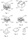
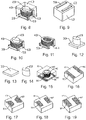
- the present invention embodied in Fig.1-14 , 25-28 and the example of Fig.15-24 not forming part of the present invention provides an inductor, comprising preparing a mounted inner core ( Figs. 3 , 10 , 20 ) by using an enameled coil (4A, 4B, 4C) and a core rod (2A, 2B, 2C, 3A, 3B, 3C); putting the mounted inner core ( Figs.
- the electrodes (5A, 5B, 5C, 5D, 5E, 5F, 6A, 6B, 6C, 6D, 6E, 6F) are buried into the centre of the outer encasing layer, and the electrodes (5A, 5B, 5C, 5D, 5E, 5F, 6A, 6B, 6C, 6D, 6E, 6F) can be formed by extending and bending the enameled coil or be formed by connecting the enameled coil to the corresponding end faces through the processing such as spot welding, soldering, film plating with silver paste, electroplating and the like, thereby the inductor is manufactured.
- the mounted inner core ( Figs. 3 , 10 , 20 ) comprises the enameled coil (4A, 4B,4C) and the core shaft (2A, 2B, 2C, 3A, 3B, 3C) disposed in the inner diameter of the enameled coil;
- the mounted inner core ( Figs. 3 , 10 , 20 ) may be in the shape of a square ( Figs. 1 , 8, 15 ), a circle ( Fig. 27 ) or a polygon ( Fig. 25 ); the electrodes of the mounted inner core ( Figs.
- the mounted inner core ( Figs. 3 , 10 , 20 ) is buried into the centre of the outer encasing layer so that the both ends of the exposed electrodes are encased by a small part of the outer encasing layer.
- the enameled coil (4A, 4B, 4C) may be in the shape of a circle or an oval; the enameled coil may comprise a round enameled wire or a flat enameled wire according to wire shape; leading-outs of the enameled coil may be formed, by winding the wire, to be in the same direction or opposite directions, respectively; the leading-outs of the enameled coil may be on the bottom or sides of the inductor; the enameled coil may be formed by winding the wire in a clockwise or counterclockwise direction; the enameled coil may comprise a single layer or multiple layers; and the enameled coil may be formed through winding and stacking the wire by wide faces or narrow faces thereof.
- the core shaft (2A, 2B, 2C, 3A, 3B, 3C) may be of a 'T' shape or a 'rod' shape; the core shaft in 'T' shape may be formed integrally, of the same material, into the 'T' shape, or may be formed into the 'T' shape by combining a rod with a sheet-shaped base which each other are made of different materials and are separated; and the core shaft is made of a material such as manganese zinc, nickel zinc, iron powder core or alloy powder, or is made of a combination of various materials such as manganese zinc, nickel zinc, iron powder core and alloy powder.
- the outer encasing layer (1A, 1B, 1C) is formed of metal powder particles through die-casting process; the metal powder particles are formed by selecting, according to requirements for properties, corresponding alloy powder, reduced iron powder, carbonyl iron powder or ferrite material and corresponding adhesive resin containing a curing agent to be stirred fully and mixed; or the metal power particles are formed by selecting, according to requirements for properties, a combination of various metal powders such as alloy powder, reduced iron powder, carbonyl iron powder or ferrite material and corresponding adhesive resin containing a curing agent to be stirred fully and mixed; and the adhesive resin comprises epoxy resin, phenolic resin, phenolic epoxy resin, o-cresol formaldehyde epoxy resin or a mixture of multiple resins and corresponding curing agent as well as other organic solvents.
- the electrodes may be formed by terminals of the enameled coil connected thereto or may be formed directly by extending and bending the enameled coil, or be formed by flattening or thinning the enameled coil, then performing soldering or electroplating based on the flattening or thinning of the enameled coil and directly extending the enameled coil; or be formed by connecting the enameled coil to corresponding end faces through a process such as spot welding, soldering, film plating with silver paste and electroplating.
- Both ends of the electrodes (5A, 5B, 5C, 5D, 5E, 5F, 6A, 6B, 6C, 6D, 6E, 6F) are buried in the outer encasing layer deeply, and exposed middle sections of the electrodes are cleaned to become smooth end faces by grinding with a grinding wheel or stripping paint with laser and are soldered or electroplated to form final electrodes of the inductor.
- Another way for forming the electrodes (5A, 5B, 5C, 5D, 5E, 5F, 6A, 6B, 6C, 6D, 6E, 6F) is to form the electrodes previously by performing electroplating or film plating with silver paste on both ends and the bottom of the mounted inner core; and the electrodes are connected electrically to the internal coil through soldering and spot welding.
- the electrodes (5A, 5B, 5C, 5D, 5E, 5F, 6A, 6B, 6C, 6D, 6E, 6F) have bottoms which can be made into various shapes, depending on requirements, such as symmetrical or asymmetrical strips, squares, and trapezoids.
- the inductor can have an appearance of a square, a circle or a polygon; the inductor can be spray-painted or be not spray-painted; and the height of the inductor can be adjusted correspondingly according to the design requirements and the performance parameters.
- a method for manufacturing an inductor characterized in that the method comprises the steps of:
- the enameled coil in the step (1) is in the shape of a circle or an oval; the enameled coil can comprise a round enameled wire or a flat enameled wire according to wire shape; leading-outs of the enameled coil are formed, by winding the wire, to be in the same direction or opposite directions, respectively; the leading-outs of the enameled coil are on the bottom or sides of the inductor; the enameled coil is formed by winding the wire in a clockwise or counterclockwise direction; the enameled coil comprises a single layer or multiple layers; and the enameled coil is formed through winding and stacking the wire by wide or narrow faces thereof.
- the mounted inner core in the step (2) comprises the enameled coil and the core shaft disposed in the inner diameter of the enameled coil;
- the mounted inner core may be in the shape of a square, a circle or a polygon;
- the electrodes of the mounted inner core may be formed by extended portions of the coil or are formed by previously electroplating or film plating with the silver paste on both ends and the bottom of the mounted inner core;
- the mounted inner core is buried into the centre of the outer encasing layer so that both ends of the exposed electrodes are encased by a small part of the outer encasing layer.
- the core shaft in the step (2) is of a 'T' shape or a 'rod' shape; the core shaft in 'T' shape is formed integrally, of the same material, into the 'T' shape, or is formed the 'T' shape by combining a 'rod' with a sheet-shaped base which each other are made of different materials and are separated; and the core shaft is made of a material of manganese zinc, nickel zinc, iron powder core or alloy powder, or is made of a combination of various materials such as manganese zinc, nickel zinc, iron powder core and alloy powder.
- the outer encasing layer in the step (4) is formed of metal powder particles through die-casting process; the metal powder particles are formed by selecting, according to requirements for properties, corresponding alloy powder, reduced iron powder, carbonyl iron powder or ferrite material and corresponding adhesive resin containing a curing agent to be stirred fully and mixed; or the metal power particles are formed by selecting, according to requirements for properties, a combination of various metal powders such as alloy powder, reduced iron powder, carbonyl iron powder, or ferrite material and corresponding adhesive resin containing a curing agent to be stirred fully and mixed; and the adhesive resin comprises epoxy resin, phenolic resin, phenolic epoxy resin, o-cresol formaldehyde epoxy resin or a mixture of multiple resins and corresponding curing agent as well as other organic solvents.
- the one way for forming the electrodes in the step (5) is that the electrodes are formed by terminals of the enameled coil connected to the coil or are formed by directly extending and bending the enameled coil, or are formed by flattening or thinning the enameled coil, then performing soldering or electroplating based on the flattening or thinning of the enameled coil and directly extending the enameled coil; or are formed by connecting the enameled coil to corresponding end faces through a process such as spot welding, soldering, film plating with silver paste and electroplating.
- the both ends of the electrodes in the step (5) are buried in the outer encasing layer deeply, and the exposed middle sections of the electrodes are cleaned to become smooth end faces by grinding with a grinding wheel or stripping paint with laser and are soldered or electroplated to form final electrodes of the inductor.
- the another way for forming the electrodes in step (6) is to form the electrodes previously by performing electroplating or film plating with silver paste on both ends and the bottom of the mounted inner core; the electrodes are connected electrically to the internal coil through soldering and spot welding; and the inductor is formed.
- the electrodes in the step (6) have bottom which can be made into various shapes such as symmetrical or asymmetrical strips, squares, trapezoids depending on requirements.
- the core shaft can be combined to be of different materials, thereby providing multiple electrical parameter variations for the inductors of the same specifications so as to meet demands of the client on designs of various electrical performances under the same volume.
Landscapes
- Engineering & Computer Science (AREA)
- Power Engineering (AREA)
- Manufacturing & Machinery (AREA)
- Microelectronics & Electronic Packaging (AREA)
- Physics & Mathematics (AREA)
- Fluid Mechanics (AREA)
- General Physics & Mathematics (AREA)
- Coils Or Transformers For Communication (AREA)
- Manufacturing Cores, Coils, And Magnets (AREA)
Priority Applications (2)
| Application Number | Priority Date | Filing Date | Title |
|---|---|---|---|
| EP17177887.1A EP3249661B1 (en) | 2014-04-01 | 2015-03-27 | Inductor |
| PL15713459T PL3036748T3 (pl) | 2014-04-01 | 2015-03-27 | Induktor oraz sposób jego wytwarzania |
Applications Claiming Priority (2)
| Application Number | Priority Date | Filing Date | Title |
|---|---|---|---|
| CN201410129094.2A CN103915236A (zh) | 2014-04-01 | 2014-04-01 | 一种新型电感及其制造方法 |
| PCT/EP2015/056758 WO2015150274A1 (en) | 2014-04-01 | 2015-03-27 | Novel inductor and method for manufacturing the same |
Related Child Applications (2)
| Application Number | Title | Priority Date | Filing Date |
|---|---|---|---|
| EP17177887.1A Division EP3249661B1 (en) | 2014-04-01 | 2015-03-27 | Inductor |
| EP17177887.1A Division-Into EP3249661B1 (en) | 2014-04-01 | 2015-03-27 | Inductor |
Publications (2)
| Publication Number | Publication Date |
|---|---|
| EP3036748A1 EP3036748A1 (en) | 2016-06-29 |
| EP3036748B1 true EP3036748B1 (en) | 2017-09-13 |
Family
ID=51040846
Family Applications (2)
| Application Number | Title | Priority Date | Filing Date |
|---|---|---|---|
| EP15713459.4A Active EP3036748B1 (en) | 2014-04-01 | 2015-03-27 | Inductor and method of manufacturing the same |
| EP17177887.1A Active EP3249661B1 (en) | 2014-04-01 | 2015-03-27 | Inductor |
Family Applications After (1)
| Application Number | Title | Priority Date | Filing Date |
|---|---|---|---|
| EP17177887.1A Active EP3249661B1 (en) | 2014-04-01 | 2015-03-27 | Inductor |
Country Status (16)
| Country | Link |
|---|---|
| EP (2) | EP3036748B1 (pl) |
| JP (1) | JP6329637B2 (pl) |
| KR (1) | KR101924941B1 (pl) |
| CN (1) | CN103915236A (pl) |
| CA (1) | CA2944603C (pl) |
| DK (1) | DK3036748T3 (pl) |
| ES (2) | ES2649190T3 (pl) |
| HU (1) | HUE035368T2 (pl) |
| IL (1) | IL247414B (pl) |
| MX (1) | MX358654B (pl) |
| NO (1) | NO3036748T3 (pl) |
| PL (1) | PL3036748T3 (pl) |
| PT (1) | PT3036748T (pl) |
| RU (1) | RU2649413C9 (pl) |
| TW (1) | TWI656542B (pl) |
| WO (1) | WO2015150274A1 (pl) |
Families Citing this family (34)
| Publication number | Priority date | Publication date | Assignee | Title |
|---|---|---|---|---|
| CN109903984B (zh) * | 2014-09-11 | 2021-10-22 | 胜美达集团株式会社 | 线圈元件的制造方法以及线圈元件 |
| JP2016157751A (ja) | 2015-02-23 | 2016-09-01 | スミダコーポレーション株式会社 | 電子部品 |
| JP6197829B2 (ja) * | 2015-05-30 | 2017-09-20 | 株式会社村田製作所 | 表面実装インダクタ |
| CN106469607B (zh) * | 2015-08-19 | 2020-10-27 | 胜美达集团株式会社 | 一种线圈元器件的制造方法及用于制造此线圈元器件的模具设备 |
| JP6503975B2 (ja) * | 2015-08-21 | 2019-04-24 | 株式会社村田製作所 | 表面実装インダクタの製造方法 |
| CN105355408B (zh) * | 2015-11-18 | 2018-02-13 | 宁波韵升电子元器件技术有限公司 | 一种模压表面贴装电感的制造方法 |
| DE102015120162A1 (de) * | 2015-11-20 | 2017-05-24 | Epcos Ag | SMD-Induktivität mit hoher Spitzenstrombelastbarkeit und niedrigen Verlusten und Verfahren zur Herstellung |
| CN105405631A (zh) * | 2015-12-30 | 2016-03-16 | 深圳市麦捷微电子科技股份有限公司 | 微型电感的制作方法 |
| CN106548851A (zh) * | 2016-08-31 | 2017-03-29 | 珠海经济特区宝诚电子有限公司 | 一种分段成型电感器及其制作方法 |
| JP6673161B2 (ja) * | 2016-11-24 | 2020-03-25 | 株式会社村田製作所 | コイル部品 |
| JP7163565B2 (ja) * | 2017-05-11 | 2022-11-01 | スミダコーポレーション株式会社 | コイル部品 |
| CN107610879B (zh) * | 2017-09-28 | 2021-07-20 | 中国科学院微电子研究所 | 一种柱形电感及其制作方法 |
| JP7103787B2 (ja) * | 2017-12-27 | 2022-07-20 | 太陽誘電株式会社 | コイル部品及び電子機器 |
| KR101997550B1 (ko) * | 2018-02-08 | 2019-07-08 | 박혜정 | 0.02~0.03mm 초소형 에나멜 코일 와인딩·터미널단자퓨징으로 이루어진 VCF AF 액츄에이터용 코일어셈블리모듈 자동제조장치 및 방법 |
| JP6784269B2 (ja) * | 2018-03-01 | 2020-11-11 | 株式会社村田製作所 | 表面実装インダクタ |
| JP6819632B2 (ja) * | 2018-03-01 | 2021-01-27 | 株式会社村田製作所 | 表面実装インダクタ |
| WO2019178737A1 (zh) * | 2018-03-20 | 2019-09-26 | 深圳顺络电子股份有限公司 | 一种电感元件及制造方法 |
| CN108389679A (zh) * | 2018-03-20 | 2018-08-10 | 深圳顺络电子股份有限公司 | 一种电感元件及制造方法 |
| CN110895989A (zh) * | 2018-08-23 | 2020-03-20 | 广东理标信息科技有限公司 | 一种一体成型电感器及其制作方法 |
| KR102593473B1 (ko) | 2019-03-11 | 2023-10-23 | 니코벤처스 트레이딩 리미티드 | 에어로졸 제공 디바이스 |
| KR102279305B1 (ko) * | 2019-04-16 | 2021-07-21 | 삼성전기주식회사 | 코일 부품 |
| CN111899970A (zh) * | 2019-05-06 | 2020-11-06 | 奇力新电子股份有限公司 | 电感器的制备方法 |
| JP6734444B2 (ja) * | 2019-06-27 | 2020-08-05 | 太陽誘電株式会社 | コイル部品及びその製造方法,電子機器 |
| DE102019211439A1 (de) | 2019-07-31 | 2021-02-04 | Würth Elektronik eiSos Gmbh & Co. KG | Verfahren zur Herstellung eines induktiven Bauteils sowie induktives Bauteil |
| CN110718386A (zh) * | 2019-10-21 | 2020-01-21 | 通友智能装备(江苏)有限公司 | 一种一体成型电感器的制作工艺 |
| CN113035528A (zh) * | 2019-12-24 | 2021-06-25 | 佳邦科技股份有限公司 | 无载具底部电极一体成型功率电感及其制造方法 |
| CN111508694A (zh) * | 2020-05-19 | 2020-08-07 | 三积瑞科技(苏州)有限公司 | 超低阻抗热压成型电感及其制造方法 |
| CN111710507A (zh) * | 2020-06-16 | 2020-09-25 | 湖南奇力新电子科技有限公司 | 一种dip转smd的一体成型电感结构 |
| CN112103029B (zh) * | 2020-09-16 | 2022-03-11 | 横店集团东磁股份有限公司 | 一种电感器及其制作方法 |
| JP7014273B2 (ja) * | 2020-10-06 | 2022-02-01 | 株式会社村田製作所 | 表面実装インダクタ |
| CN112927882B (zh) * | 2021-01-25 | 2022-05-27 | 合泰盟方电子(深圳)股份有限公司 | 一种用于一体成型电感器的金属软磁粉末构件 |
| CN113436830A (zh) * | 2021-05-25 | 2021-09-24 | 深圳顺络电子股份有限公司 | 一种塑模成型元器件及其制造方法 |
| US20230170124A1 (en) * | 2021-11-29 | 2023-06-01 | Tai-Tech Advanced Electronics Co., Ltd. | Inductance value increasing structure |
| TWI827523B (zh) * | 2023-06-30 | 2023-12-21 | 奇力新電子股份有限公司 | 磁性裝置的製造方法及磁性裝置 |
Citations (1)
| Publication number | Priority date | Publication date | Assignee | Title |
|---|---|---|---|---|
| EP2779182A2 (en) * | 2013-03-14 | 2014-09-17 | Sumida Corporation | Electronic component and method for manufacturing electronic component |
Family Cites Families (27)
| Publication number | Priority date | Publication date | Assignee | Title |
|---|---|---|---|---|
| JPH02103916A (ja) | 1988-10-13 | 1990-04-17 | Matsushita Electric Ind Co Ltd | インダクタンス素子の製造方法 |
| JPH0352204A (ja) * | 1989-07-20 | 1991-03-06 | Matsushita Electric Ind Co Ltd | インダクタンス素子およびその製造方法 |
| JP3013197B2 (ja) * | 1990-11-30 | 2000-02-28 | 株式会社トーキン | インダクタ及びその製造方法 |
| JP2003168610A (ja) * | 2001-11-29 | 2003-06-13 | Toko Inc | インダクタンス素子 |
| JP2006165429A (ja) * | 2004-12-10 | 2006-06-22 | Toko Inc | 巻線型インダクタ |
| JP2006196731A (ja) * | 2005-01-14 | 2006-07-27 | Toko Inc | 巻線型インダクタ |
| US20080036566A1 (en) * | 2006-08-09 | 2008-02-14 | Andrzej Klesyk | Electronic Component And Methods Relating To Same |
| JP2009105158A (ja) * | 2007-10-22 | 2009-05-14 | Tokyo Coil Engineering Kk | インダクタ用コイル構造及びインダクタ |
| JP5084459B2 (ja) * | 2007-11-15 | 2012-11-28 | 太陽誘電株式会社 | インダクタ及びその製造方法 |
| TWM350081U (en) * | 2008-04-29 | 2009-02-01 | ming-ming Xie | Inductor structure |
| US20090278650A1 (en) * | 2008-05-12 | 2009-11-12 | Shieh Ming-Ming | Inductor |
| JP2010087240A (ja) * | 2008-09-30 | 2010-04-15 | Tdk Corp | 電子部品及び電子部品の製造方法 |
| US20100134233A1 (en) * | 2008-11-28 | 2010-06-03 | Shih-Jen Wang | Inductor and method for making the same |
| CN101552091B (zh) * | 2008-12-31 | 2012-05-30 | 王向群 | 金属粉末注射成型电感器及其加工方法 |
| CN201489940U (zh) * | 2009-07-23 | 2010-05-26 | 美桀电子科技(深圳)有限公司 | 电感元件 |
| CN201590319U (zh) * | 2009-11-27 | 2010-09-22 | 深圳市科达嘉电子有限公司 | 一种贴片大功率电感器 |
| JP5407817B2 (ja) * | 2009-12-07 | 2014-02-05 | パナソニック株式会社 | コイル部品の製造方法 |
| RU2427067C1 (ru) * | 2009-12-25 | 2011-08-20 | Сергей Михайлович Есаков | Магнитоэлектрический генератор |
| US9136050B2 (en) * | 2010-07-23 | 2015-09-15 | Cyntec Co., Ltd. | Magnetic device and method of manufacturing the same |
| JP4795489B1 (ja) * | 2011-01-21 | 2011-10-19 | 太陽誘電株式会社 | コイル部品 |
| TW201236035A (en) * | 2011-02-24 | 2012-09-01 | Prejection Ind Corp | Process for inductor |
| US20120268231A1 (en) * | 2011-04-19 | 2012-10-25 | Shang S R | Hot/cold forming and assembling magnetic component |
| JP2012234869A (ja) * | 2011-04-28 | 2012-11-29 | Taiyo Yuden Co Ltd | コイル部品 |
| JP5336543B2 (ja) * | 2011-04-28 | 2013-11-06 | 太陽誘電株式会社 | コイル部品 |
| CN202487309U (zh) * | 2012-02-24 | 2012-10-10 | 百徽股份有限公司 | 铁芯可置换的绕线式电感组件 |
| CN202887902U (zh) * | 2012-09-17 | 2013-04-17 | 深圳顺络电子股份有限公司 | 模塑成型功率电感元件 |
| CN203433952U (zh) * | 2013-06-18 | 2014-02-12 | 赵宜泰 | 电感器结构 |
-
2014
- 2014-04-01 CN CN201410129094.2A patent/CN103915236A/zh active Pending
-
2015
- 2015-03-27 ES ES15713459.4T patent/ES2649190T3/es active Active
- 2015-03-27 JP JP2016556254A patent/JP6329637B2/ja active Active
- 2015-03-27 PL PL15713459T patent/PL3036748T3/pl unknown
- 2015-03-27 WO PCT/EP2015/056758 patent/WO2015150274A1/en not_active Ceased
- 2015-03-27 EP EP15713459.4A patent/EP3036748B1/en active Active
- 2015-03-27 EP EP17177887.1A patent/EP3249661B1/en active Active
- 2015-03-27 HU HUE15713459A patent/HUE035368T2/en unknown
- 2015-03-27 PT PT157134594T patent/PT3036748T/pt unknown
- 2015-03-27 ES ES17177887T patent/ES2949708T3/es active Active
- 2015-03-27 CA CA2944603A patent/CA2944603C/en active Active
- 2015-03-27 NO NO15713459A patent/NO3036748T3/no unknown
- 2015-03-27 MX MX2016011405A patent/MX358654B/es active IP Right Grant
- 2015-03-27 RU RU2016136210A patent/RU2649413C9/ru active
- 2015-03-27 DK DK15713459.4T patent/DK3036748T3/en active
- 2015-03-27 KR KR1020167027292A patent/KR101924941B1/ko active Active
- 2015-03-31 TW TW104110471A patent/TWI656542B/zh active
-
2016
- 2016-08-22 IL IL247414A patent/IL247414B/en active IP Right Grant
Patent Citations (1)
| Publication number | Priority date | Publication date | Assignee | Title |
|---|---|---|---|---|
| EP2779182A2 (en) * | 2013-03-14 | 2014-09-17 | Sumida Corporation | Electronic component and method for manufacturing electronic component |
Also Published As
| Publication number | Publication date |
|---|---|
| TWI656542B (zh) | 2019-04-11 |
| RU2649413C9 (ru) | 2018-07-11 |
| TW201603065A (zh) | 2016-01-16 |
| CA2944603A1 (en) | 2015-10-08 |
| IL247414B (en) | 2020-07-30 |
| ES2949708T3 (es) | 2023-10-02 |
| ES2649190T3 (es) | 2018-01-10 |
| KR20160129070A (ko) | 2016-11-08 |
| EP3249661B1 (en) | 2023-05-03 |
| EP3036748A1 (en) | 2016-06-29 |
| PL3036748T3 (pl) | 2018-01-31 |
| JP6329637B2 (ja) | 2018-05-23 |
| CA2944603C (en) | 2018-06-19 |
| NO3036748T3 (pl) | 2018-02-10 |
| PT3036748T (pt) | 2017-11-29 |
| MX358654B (es) | 2018-08-30 |
| JP2017510072A (ja) | 2017-04-06 |
| MX2016011405A (es) | 2017-02-02 |
| IL247414A0 (en) | 2016-11-30 |
| HUE035368T2 (en) | 2018-05-02 |
| EP3249661A1 (en) | 2017-11-29 |
| WO2015150274A1 (en) | 2015-10-08 |
| RU2649413C1 (ru) | 2018-04-03 |
| CN103915236A (zh) | 2014-07-09 |
| DK3036748T3 (en) | 2018-01-02 |
| KR101924941B1 (ko) | 2019-02-27 |
Similar Documents
| Publication | Publication Date | Title |
|---|---|---|
| EP3036748B1 (en) | Inductor and method of manufacturing the same | |
| US12094633B2 (en) | Method of manufacturing an electronic component | |
| TWI342574B (pl) | ||
| JP5450675B2 (ja) | 面実装インダクタとその製造方法 | |
| CN106469603B (zh) | 线圈电子组件 | |
| US20130307655A1 (en) | Surface Mount Inductor and Method for Producing Surface Mount Inductor | |
| KR101792279B1 (ko) | 인덕터 및 인덕터 제조 방법 | |
| JP7605656B2 (ja) | コイル部品、回路基板、電子機器、及びコイル部品の製造方法 | |
| HK1242466A1 (en) | Inductor | |
| HK1242466B (en) | Inductor | |
| JP6927115B2 (ja) | 面実装インダクタおよびその製造方法 |
Legal Events
| Date | Code | Title | Description |
|---|---|---|---|
| PUAI | Public reference made under article 153(3) epc to a published international application that has entered the european phase |
Free format text: ORIGINAL CODE: 0009012 |
|
| 17P | Request for examination filed |
Effective date: 20160407 |
|
| AK | Designated contracting states |
Kind code of ref document: A1 Designated state(s): AL AT BE BG CH CY CZ DE DK EE ES FI FR GB GR HR HU IE IS IT LI LT LU LV MC MK MT NL NO PL PT RO RS SE SI SK SM TR |
|
| AX | Request for extension of the european patent |
Extension state: BA ME |
|
| 17Q | First examination report despatched |
Effective date: 20160727 |
|
| STAA | Information on the status of an ep patent application or granted ep patent |
Free format text: STATUS: EXAMINATION IS IN PROGRESS |
|
| GRAP | Despatch of communication of intention to grant a patent |
Free format text: ORIGINAL CODE: EPIDOSNIGR1 |
|
| STAA | Information on the status of an ep patent application or granted ep patent |
Free format text: STATUS: GRANT OF PATENT IS INTENDED |
|
| DAV | Request for validation of the european patent (deleted) | ||
| DAX | Request for extension of the european patent (deleted) | ||
| INTG | Intention to grant announced |
Effective date: 20170323 |
|
| GRAS | Grant fee paid |
Free format text: ORIGINAL CODE: EPIDOSNIGR3 |
|
| GRAA | (expected) grant |
Free format text: ORIGINAL CODE: 0009210 |
|
| STAA | Information on the status of an ep patent application or granted ep patent |
Free format text: STATUS: THE PATENT HAS BEEN GRANTED |
|
| AK | Designated contracting states |
Kind code of ref document: B1 Designated state(s): AL AT BE BG CH CY CZ DE DK EE ES FI FR GB GR HR HU IE IS IT LI LT LU LV MC MK MT NL NO PL PT RO RS SE SI SK SM TR |
|
| REG | Reference to a national code |
Ref country code: GB Ref legal event code: FG4D |
|
| REG | Reference to a national code |
Ref country code: CH Ref legal event code: EP |
|
| REG | Reference to a national code |
Ref country code: IE Ref legal event code: FG4D |
|
| REG | Reference to a national code |
Ref country code: AT Ref legal event code: REF Ref document number: 928890 Country of ref document: AT Kind code of ref document: T Effective date: 20171015 |
|
| REG | Reference to a national code |
Ref country code: DE Ref legal event code: R096 Ref document number: 602015004784 Country of ref document: DE |
|
| REG | Reference to a national code |
Ref country code: NL Ref legal event code: FP Ref country code: PT Ref legal event code: SC4A Ref document number: 3036748 Country of ref document: PT Date of ref document: 20171129 Kind code of ref document: T Free format text: AVAILABILITY OF NATIONAL TRANSLATION Effective date: 20171122 |
|
| REG | Reference to a national code |
Ref country code: SE Ref legal event code: TRGR Ref country code: DK Ref legal event code: T3 Effective date: 20171219 |
|
| REG | Reference to a national code |
Ref country code: ES Ref legal event code: FG2A Ref document number: 2649190 Country of ref document: ES Kind code of ref document: T3 Effective date: 20180110 |
|
| REG | Reference to a national code |
Ref country code: LT Ref legal event code: MG4D |
|
| PG25 | Lapsed in a contracting state [announced via postgrant information from national office to epo] |
Ref country code: LT Free format text: LAPSE BECAUSE OF FAILURE TO SUBMIT A TRANSLATION OF THE DESCRIPTION OR TO PAY THE FEE WITHIN THE PRESCRIBED TIME-LIMIT Effective date: 20170913 Ref country code: HR Free format text: LAPSE BECAUSE OF FAILURE TO SUBMIT A TRANSLATION OF THE DESCRIPTION OR TO PAY THE FEE WITHIN THE PRESCRIBED TIME-LIMIT Effective date: 20170913 |
|
| REG | Reference to a national code |
Ref country code: NO Ref legal event code: T2 Effective date: 20170913 |
|
| PG25 | Lapsed in a contracting state [announced via postgrant information from national office to epo] |
Ref country code: LV Free format text: LAPSE BECAUSE OF FAILURE TO SUBMIT A TRANSLATION OF THE DESCRIPTION OR TO PAY THE FEE WITHIN THE PRESCRIBED TIME-LIMIT Effective date: 20170913 Ref country code: RS Free format text: LAPSE BECAUSE OF FAILURE TO SUBMIT A TRANSLATION OF THE DESCRIPTION OR TO PAY THE FEE WITHIN THE PRESCRIBED TIME-LIMIT Effective date: 20170913 |
|
| REG | Reference to a national code |
Ref country code: FR Ref legal event code: PLFP Year of fee payment: 4 |
|
| REG | Reference to a national code |
Ref country code: SK Ref legal event code: T3 Ref document number: E 26082 Country of ref document: SK |
|
| PG25 | Lapsed in a contracting state [announced via postgrant information from national office to epo] |
Ref country code: RO Free format text: LAPSE BECAUSE OF FAILURE TO SUBMIT A TRANSLATION OF THE DESCRIPTION OR TO PAY THE FEE WITHIN THE PRESCRIBED TIME-LIMIT Effective date: 20170913 |
|
| REG | Reference to a national code |
Ref country code: HU Ref legal event code: AG4A Ref document number: E035368 Country of ref document: HU |
|
| REG | Reference to a national code |
Ref country code: GR Ref legal event code: EP Ref document number: 20170403416 Country of ref document: GR Effective date: 20180420 |
|
| PG25 | Lapsed in a contracting state [announced via postgrant information from national office to epo] |
Ref country code: SM Free format text: LAPSE BECAUSE OF FAILURE TO SUBMIT A TRANSLATION OF THE DESCRIPTION OR TO PAY THE FEE WITHIN THE PRESCRIBED TIME-LIMIT Effective date: 20170913 Ref country code: EE Free format text: LAPSE BECAUSE OF FAILURE TO SUBMIT A TRANSLATION OF THE DESCRIPTION OR TO PAY THE FEE WITHIN THE PRESCRIBED TIME-LIMIT Effective date: 20170913 Ref country code: IS Free format text: LAPSE BECAUSE OF FAILURE TO SUBMIT A TRANSLATION OF THE DESCRIPTION OR TO PAY THE FEE WITHIN THE PRESCRIBED TIME-LIMIT Effective date: 20180113 |
|
| REG | Reference to a national code |
Ref country code: DE Ref legal event code: R097 Ref document number: 602015004784 Country of ref document: DE |
|
| PLBE | No opposition filed within time limit |
Free format text: ORIGINAL CODE: 0009261 |
|
| STAA | Information on the status of an ep patent application or granted ep patent |
Free format text: STATUS: NO OPPOSITION FILED WITHIN TIME LIMIT |
|
| 26N | No opposition filed |
Effective date: 20180614 |
|
| PG25 | Lapsed in a contracting state [announced via postgrant information from national office to epo] |
Ref country code: MC Free format text: LAPSE BECAUSE OF FAILURE TO SUBMIT A TRANSLATION OF THE DESCRIPTION OR TO PAY THE FEE WITHIN THE PRESCRIBED TIME-LIMIT Effective date: 20170913 Ref country code: SI Free format text: LAPSE BECAUSE OF FAILURE TO SUBMIT A TRANSLATION OF THE DESCRIPTION OR TO PAY THE FEE WITHIN THE PRESCRIBED TIME-LIMIT Effective date: 20170913 |
|
| PG25 | Lapsed in a contracting state [announced via postgrant information from national office to epo] |
Ref country code: LU Free format text: LAPSE BECAUSE OF NON-PAYMENT OF DUE FEES Effective date: 20180327 |
|
| PG25 | Lapsed in a contracting state [announced via postgrant information from national office to epo] |
Ref country code: MT Free format text: LAPSE BECAUSE OF NON-PAYMENT OF DUE FEES Effective date: 20180327 |
|
| PG25 | Lapsed in a contracting state [announced via postgrant information from national office to epo] |
Ref country code: CY Free format text: LAPSE BECAUSE OF FAILURE TO SUBMIT A TRANSLATION OF THE DESCRIPTION OR TO PAY THE FEE WITHIN THE PRESCRIBED TIME-LIMIT Effective date: 20170913 Ref country code: MK Free format text: LAPSE BECAUSE OF NON-PAYMENT OF DUE FEES Effective date: 20170913 |
|
| PG25 | Lapsed in a contracting state [announced via postgrant information from national office to epo] |
Ref country code: AL Free format text: LAPSE BECAUSE OF FAILURE TO SUBMIT A TRANSLATION OF THE DESCRIPTION OR TO PAY THE FEE WITHIN THE PRESCRIBED TIME-LIMIT Effective date: 20170913 |
|
| REG | Reference to a national code |
Ref country code: AT Ref legal event code: UEP Ref document number: 928890 Country of ref document: AT Kind code of ref document: T Effective date: 20170913 |
|
| P01 | Opt-out of the competence of the unified patent court (upc) registered |
Effective date: 20230517 |
|
| PGFP | Annual fee paid to national office [announced via postgrant information from national office to epo] |
Ref country code: SE Payment date: 20250321 Year of fee payment: 11 |
|
| PGFP | Annual fee paid to national office [announced via postgrant information from national office to epo] |
Ref country code: DE Payment date: 20250319 Year of fee payment: 11 Ref country code: PT Payment date: 20250313 Year of fee payment: 11 |
|
| PGFP | Annual fee paid to national office [announced via postgrant information from national office to epo] |
Ref country code: DK Payment date: 20250326 Year of fee payment: 11 Ref country code: FI Payment date: 20250324 Year of fee payment: 11 Ref country code: NL Payment date: 20250319 Year of fee payment: 11 |
|
| PGFP | Annual fee paid to national office [announced via postgrant information from national office to epo] |
Ref country code: BG Payment date: 20250321 Year of fee payment: 11 |
|
| PGFP | Annual fee paid to national office [announced via postgrant information from national office to epo] |
Ref country code: HU Payment date: 20250321 Year of fee payment: 11 |
|
| PGFP | Annual fee paid to national office [announced via postgrant information from national office to epo] |
Ref country code: IE Payment date: 20250319 Year of fee payment: 11 |
|
| PGFP | Annual fee paid to national office [announced via postgrant information from national office to epo] |
Ref country code: NO Payment date: 20250321 Year of fee payment: 11 |
|
| PGFP | Annual fee paid to national office [announced via postgrant information from national office to epo] |
Ref country code: AT Payment date: 20250320 Year of fee payment: 11 Ref country code: GR Payment date: 20250320 Year of fee payment: 11 Ref country code: BE Payment date: 20250319 Year of fee payment: 11 |
|
| PGFP | Annual fee paid to national office [announced via postgrant information from national office to epo] |
Ref country code: FR Payment date: 20250325 Year of fee payment: 11 Ref country code: CZ Payment date: 20250318 Year of fee payment: 11 Ref country code: PL Payment date: 20250225 Year of fee payment: 11 |
|
| PGFP | Annual fee paid to national office [announced via postgrant information from national office to epo] |
Ref country code: IT Payment date: 20250325 Year of fee payment: 11 Ref country code: SK Payment date: 20250317 Year of fee payment: 11 Ref country code: GB Payment date: 20250321 Year of fee payment: 11 |
|
| PGFP | Annual fee paid to national office [announced via postgrant information from national office to epo] |
Ref country code: TR Payment date: 20250318 Year of fee payment: 11 |
|
| PGFP | Annual fee paid to national office [announced via postgrant information from national office to epo] |
Ref country code: ES Payment date: 20250429 Year of fee payment: 11 |
|
| PGFP | Annual fee paid to national office [announced via postgrant information from national office to epo] |
Ref country code: CH Payment date: 20250401 Year of fee payment: 11 |